EP3536310A1 - Syringe - Google Patents
Syringe Download PDFInfo
- Publication number
- EP3536310A1 EP3536310A1 EP19161189.6A EP19161189A EP3536310A1 EP 3536310 A1 EP3536310 A1 EP 3536310A1 EP 19161189 A EP19161189 A EP 19161189A EP 3536310 A1 EP3536310 A1 EP 3536310A1
- Authority
- EP
- European Patent Office
- Prior art keywords
- syringe
- stopper
- plunger
- rod
- shoulder
- Prior art date
- Legal status (The legal status is an assumption and is not a legal conclusion. Google has not performed a legal analysis and makes no representation as to the accuracy of the status listed.)
- Granted
Links
- 239000012530 fluid Substances 0.000 claims abstract description 11
- 238000002347 injection Methods 0.000 claims abstract description 10
- 239000007924 injection Substances 0.000 claims abstract description 10
- 239000003814 drug Substances 0.000 claims description 34
- 108010081667 aflibercept Proteins 0.000 claims description 6
- 229920001296 polysiloxane Polymers 0.000 claims description 6
- 229960003876 ranibizumab Drugs 0.000 claims description 6
- 208000022873 Ocular disease Diseases 0.000 claims description 5
- 102000005789 Vascular Endothelial Growth Factors Human genes 0.000 claims description 5
- 108010019530 Vascular Endothelial Growth Factors Proteins 0.000 claims description 5
- 239000005557 antagonist Substances 0.000 claims description 5
- 229960002833 aflibercept Drugs 0.000 claims description 3
- 229940071643 prefilled syringe Drugs 0.000 claims description 2
- 238000000034 method Methods 0.000 description 21
- 238000004659 sterilization and disinfection Methods 0.000 description 16
- 230000036512 infertility Effects 0.000 description 13
- 238000007789 sealing Methods 0.000 description 12
- 230000008569 process Effects 0.000 description 10
- 239000000463 material Substances 0.000 description 9
- 208000004644 retinal vein occlusion Diseases 0.000 description 8
- MHAJPDPJQMAIIY-UHFFFAOYSA-N Hydrogen peroxide Chemical compound OO MHAJPDPJQMAIIY-UHFFFAOYSA-N 0.000 description 6
- 206010060823 Choroidal neovascularisation Diseases 0.000 description 4
- 206010012688 Diabetic retinal oedema Diseases 0.000 description 4
- IAYPIBMASNFSPL-UHFFFAOYSA-N Ethylene oxide Chemical compound C1CO1 IAYPIBMASNFSPL-UHFFFAOYSA-N 0.000 description 4
- 206010073286 Pathologic myopia Diseases 0.000 description 4
- 201000011190 diabetic macular edema Diseases 0.000 description 4
- 239000007788 liquid Substances 0.000 description 4
- 238000004806 packaging method and process Methods 0.000 description 4
- 239000000047 product Substances 0.000 description 4
- 239000000243 solution Substances 0.000 description 4
- 230000008878 coupling Effects 0.000 description 3
- 238000010168 coupling process Methods 0.000 description 3
- 238000005859 coupling reaction Methods 0.000 description 3
- 239000007789 gas Substances 0.000 description 3
- 239000007787 solid Substances 0.000 description 3
- 230000001954 sterilising effect Effects 0.000 description 3
- 206010012689 Diabetic retinopathy Diseases 0.000 description 2
- 108700036276 KH902 fusion Proteins 0.000 description 2
- 239000003798 L01XE11 - Pazopanib Substances 0.000 description 2
- 208000001344 Macular Edema Diseases 0.000 description 2
- 206010025415 Macular oedema Diseases 0.000 description 2
- 206010038934 Retinopathy proliferative Diseases 0.000 description 2
- 230000009471 action Effects 0.000 description 2
- 206010064930 age-related macular degeneration Diseases 0.000 description 2
- 229960000397 bevacizumab Drugs 0.000 description 2
- 230000008859 change Effects 0.000 description 2
- 229950005748 conbercept Drugs 0.000 description 2
- 239000012634 fragment Substances 0.000 description 2
- 230000005484 gravity Effects 0.000 description 2
- 208000002780 macular degeneration Diseases 0.000 description 2
- 201000010230 macular retinal edema Diseases 0.000 description 2
- 238000004519 manufacturing process Methods 0.000 description 2
- CUIHSIWYWATEQL-UHFFFAOYSA-N pazopanib Chemical compound C1=CC2=C(C)N(C)N=C2C=C1N(C)C(N=1)=CC=NC=1NC1=CC=C(C)C(S(N)(=O)=O)=C1 CUIHSIWYWATEQL-UHFFFAOYSA-N 0.000 description 2
- 229960000639 pazopanib Drugs 0.000 description 2
- 239000004033 plastic Substances 0.000 description 2
- 108090000623 proteins and genes Proteins 0.000 description 2
- 102000004169 proteins and genes Human genes 0.000 description 2
- PNVNVHUZROJLTJ-UHFFFAOYSA-N venlafaxine Chemical compound C1=CC(OC)=CC=C1C(CN(C)C)C1(O)CCCCC1 PNVNVHUZROJLTJ-UHFFFAOYSA-N 0.000 description 2
- 239000003795 chemical substances by application Substances 0.000 description 1
- 230000001010 compromised effect Effects 0.000 description 1
- 229940079593 drug Drugs 0.000 description 1
- 229940051306 eylea Drugs 0.000 description 1
- 239000012467 final product Substances 0.000 description 1
- 239000011521 glass Substances 0.000 description 1
- 208000015181 infectious disease Diseases 0.000 description 1
- 229940102223 injectable solution Drugs 0.000 description 1
- 239000000314 lubricant Substances 0.000 description 1
- 229940076783 lucentis Drugs 0.000 description 1
- 230000007246 mechanism Effects 0.000 description 1
- 239000000203 mixture Substances 0.000 description 1
- 238000012986 modification Methods 0.000 description 1
- 230000004048 modification Effects 0.000 description 1
- 229940068196 placebo Drugs 0.000 description 1
- 239000000902 placebo Substances 0.000 description 1
Images

Classifications
-
- A—HUMAN NECESSITIES
- A61—MEDICAL OR VETERINARY SCIENCE; HYGIENE
- A61F—FILTERS IMPLANTABLE INTO BLOOD VESSELS; PROSTHESES; DEVICES PROVIDING PATENCY TO, OR PREVENTING COLLAPSING OF, TUBULAR STRUCTURES OF THE BODY, e.g. STENTS; ORTHOPAEDIC, NURSING OR CONTRACEPTIVE DEVICES; FOMENTATION; TREATMENT OR PROTECTION OF EYES OR EARS; BANDAGES, DRESSINGS OR ABSORBENT PADS; FIRST-AID KITS
- A61F9/00—Methods or devices for treatment of the eyes; Devices for putting-in contact lenses; Devices to correct squinting; Apparatus to guide the blind; Protective devices for the eyes, carried on the body or in the hand
- A61F9/007—Methods or devices for eye surgery
- A61F9/00736—Instruments for removal of intra-ocular material or intra-ocular injection, e.g. cataract instruments
-
- A—HUMAN NECESSITIES
- A61—MEDICAL OR VETERINARY SCIENCE; HYGIENE
- A61M—DEVICES FOR INTRODUCING MEDIA INTO, OR ONTO, THE BODY; DEVICES FOR TRANSDUCING BODY MEDIA OR FOR TAKING MEDIA FROM THE BODY; DEVICES FOR PRODUCING OR ENDING SLEEP OR STUPOR
- A61M5/00—Devices for bringing media into the body in a subcutaneous, intra-vascular or intramuscular way; Accessories therefor, e.g. filling or cleaning devices, arm-rests
- A61M5/001—Apparatus specially adapted for cleaning or sterilising syringes or needles
-
- A—HUMAN NECESSITIES
- A61—MEDICAL OR VETERINARY SCIENCE; HYGIENE
- A61M—DEVICES FOR INTRODUCING MEDIA INTO, OR ONTO, THE BODY; DEVICES FOR TRANSDUCING BODY MEDIA OR FOR TAKING MEDIA FROM THE BODY; DEVICES FOR PRODUCING OR ENDING SLEEP OR STUPOR
- A61M5/00—Devices for bringing media into the body in a subcutaneous, intra-vascular or intramuscular way; Accessories therefor, e.g. filling or cleaning devices, arm-rests
- A61M5/178—Syringes
- A61M5/28—Syringe ampoules or carpules, i.e. ampoules or carpules provided with a needle
-
- A—HUMAN NECESSITIES
- A61—MEDICAL OR VETERINARY SCIENCE; HYGIENE
- A61M—DEVICES FOR INTRODUCING MEDIA INTO, OR ONTO, THE BODY; DEVICES FOR TRANSDUCING BODY MEDIA OR FOR TAKING MEDIA FROM THE BODY; DEVICES FOR PRODUCING OR ENDING SLEEP OR STUPOR
- A61M5/00—Devices for bringing media into the body in a subcutaneous, intra-vascular or intramuscular way; Accessories therefor, e.g. filling or cleaning devices, arm-rests
- A61M5/178—Syringes
- A61M5/31—Details
- A61M5/315—Pistons; Piston-rods; Guiding, blocking or restricting the movement of the rod or piston; Appliances on the rod for facilitating dosing ; Dosing mechanisms
- A61M5/31501—Means for blocking or restricting the movement of the rod or piston
- A61M5/31505—Integral with the syringe barrel, i.e. connected to the barrel so as to make up a single complete piece or unit
-
- A—HUMAN NECESSITIES
- A61—MEDICAL OR VETERINARY SCIENCE; HYGIENE
- A61M—DEVICES FOR INTRODUCING MEDIA INTO, OR ONTO, THE BODY; DEVICES FOR TRANSDUCING BODY MEDIA OR FOR TAKING MEDIA FROM THE BODY; DEVICES FOR PRODUCING OR ENDING SLEEP OR STUPOR
- A61M5/00—Devices for bringing media into the body in a subcutaneous, intra-vascular or intramuscular way; Accessories therefor, e.g. filling or cleaning devices, arm-rests
- A61M5/178—Syringes
- A61M5/31—Details
- A61M5/315—Pistons; Piston-rods; Guiding, blocking or restricting the movement of the rod or piston; Appliances on the rod for facilitating dosing ; Dosing mechanisms
- A61M5/31511—Piston or piston-rod constructions, e.g. connection of piston with piston-rod
- A61M5/31513—Piston constructions to improve sealing or sliding
-
- A—HUMAN NECESSITIES
- A61—MEDICAL OR VETERINARY SCIENCE; HYGIENE
- A61P—SPECIFIC THERAPEUTIC ACTIVITY OF CHEMICAL COMPOUNDS OR MEDICINAL PREPARATIONS
- A61P27/00—Drugs for disorders of the senses
- A61P27/02—Ophthalmic agents
-
- A—HUMAN NECESSITIES
- A61—MEDICAL OR VETERINARY SCIENCE; HYGIENE
- A61P—SPECIFIC THERAPEUTIC ACTIVITY OF CHEMICAL COMPOUNDS OR MEDICINAL PREPARATIONS
- A61P43/00—Drugs for specific purposes, not provided for in groups A61P1/00-A61P41/00
-
- A—HUMAN NECESSITIES
- A61—MEDICAL OR VETERINARY SCIENCE; HYGIENE
- A61F—FILTERS IMPLANTABLE INTO BLOOD VESSELS; PROSTHESES; DEVICES PROVIDING PATENCY TO, OR PREVENTING COLLAPSING OF, TUBULAR STRUCTURES OF THE BODY, e.g. STENTS; ORTHOPAEDIC, NURSING OR CONTRACEPTIVE DEVICES; FOMENTATION; TREATMENT OR PROTECTION OF EYES OR EARS; BANDAGES, DRESSINGS OR ABSORBENT PADS; FIRST-AID KITS
- A61F9/00—Methods or devices for treatment of the eyes; Devices for putting-in contact lenses; Devices to correct squinting; Apparatus to guide the blind; Protective devices for the eyes, carried on the body or in the hand
- A61F9/0008—Introducing ophthalmic products into the ocular cavity or retaining products therein
- A61F9/0017—Introducing ophthalmic products into the ocular cavity or retaining products therein implantable in, or in contact with, the eye, e.g. ocular inserts
-
- A—HUMAN NECESSITIES
- A61—MEDICAL OR VETERINARY SCIENCE; HYGIENE
- A61M—DEVICES FOR INTRODUCING MEDIA INTO, OR ONTO, THE BODY; DEVICES FOR TRANSDUCING BODY MEDIA OR FOR TAKING MEDIA FROM THE BODY; DEVICES FOR PRODUCING OR ENDING SLEEP OR STUPOR
- A61M5/00—Devices for bringing media into the body in a subcutaneous, intra-vascular or intramuscular way; Accessories therefor, e.g. filling or cleaning devices, arm-rests
- A61M5/178—Syringes
- A61M5/31—Details
- A61M2005/3103—Leak prevention means for distal end of syringes, i.e. syringe end for mounting a needle
- A61M2005/3104—Caps for syringes without needle
-
- A—HUMAN NECESSITIES
- A61—MEDICAL OR VETERINARY SCIENCE; HYGIENE
- A61M—DEVICES FOR INTRODUCING MEDIA INTO, OR ONTO, THE BODY; DEVICES FOR TRANSDUCING BODY MEDIA OR FOR TAKING MEDIA FROM THE BODY; DEVICES FOR PRODUCING OR ENDING SLEEP OR STUPOR
- A61M5/00—Devices for bringing media into the body in a subcutaneous, intra-vascular or intramuscular way; Accessories therefor, e.g. filling or cleaning devices, arm-rests
- A61M5/178—Syringes
- A61M5/31—Details
- A61M2005/3117—Means preventing contamination of the medicament compartment of a syringe
- A61M2005/3118—Means preventing contamination of the medicament compartment of a syringe via the distal end of a syringe, i.e. syringe end for mounting a needle cannula
- A61M2005/312—Means preventing contamination of the medicament compartment of a syringe via the distal end of a syringe, i.e. syringe end for mounting a needle cannula comprising sealing means, e.g. severable caps, to be removed prior to injection by, e.g. tearing or twisting
-
- A—HUMAN NECESSITIES
- A61—MEDICAL OR VETERINARY SCIENCE; HYGIENE
- A61M—DEVICES FOR INTRODUCING MEDIA INTO, OR ONTO, THE BODY; DEVICES FOR TRANSDUCING BODY MEDIA OR FOR TAKING MEDIA FROM THE BODY; DEVICES FOR PRODUCING OR ENDING SLEEP OR STUPOR
- A61M5/00—Devices for bringing media into the body in a subcutaneous, intra-vascular or intramuscular way; Accessories therefor, e.g. filling or cleaning devices, arm-rests
- A61M5/178—Syringes
- A61M5/31—Details
- A61M5/3129—Syringe barrels
- A61M5/3137—Specially designed finger grip means, e.g. for easy manipulation of the syringe rod
- A61M2005/3139—Finger grips not integrally formed with the syringe barrel, e.g. using adapter with finger grips
-
- A—HUMAN NECESSITIES
- A61—MEDICAL OR VETERINARY SCIENCE; HYGIENE
- A61M—DEVICES FOR INTRODUCING MEDIA INTO, OR ONTO, THE BODY; DEVICES FOR TRANSDUCING BODY MEDIA OR FOR TAKING MEDIA FROM THE BODY; DEVICES FOR PRODUCING OR ENDING SLEEP OR STUPOR
- A61M5/00—Devices for bringing media into the body in a subcutaneous, intra-vascular or intramuscular way; Accessories therefor, e.g. filling or cleaning devices, arm-rests
- A61M5/178—Syringes
- A61M5/31—Details
- A61M5/315—Pistons; Piston-rods; Guiding, blocking or restricting the movement of the rod or piston; Appliances on the rod for facilitating dosing ; Dosing mechanisms
- A61M5/31501—Means for blocking or restricting the movement of the rod or piston
- A61M2005/31508—Means for blocking or restricting the movement of the rod or piston provided on the piston-rod
-
- A—HUMAN NECESSITIES
- A61—MEDICAL OR VETERINARY SCIENCE; HYGIENE
- A61M—DEVICES FOR INTRODUCING MEDIA INTO, OR ONTO, THE BODY; DEVICES FOR TRANSDUCING BODY MEDIA OR FOR TAKING MEDIA FROM THE BODY; DEVICES FOR PRODUCING OR ENDING SLEEP OR STUPOR
- A61M2210/00—Anatomical parts of the body
- A61M2210/06—Head
- A61M2210/0612—Eyes
-
- A—HUMAN NECESSITIES
- A61—MEDICAL OR VETERINARY SCIENCE; HYGIENE
- A61M—DEVICES FOR INTRODUCING MEDIA INTO, OR ONTO, THE BODY; DEVICES FOR TRANSDUCING BODY MEDIA OR FOR TAKING MEDIA FROM THE BODY; DEVICES FOR PRODUCING OR ENDING SLEEP OR STUPOR
- A61M5/00—Devices for bringing media into the body in a subcutaneous, intra-vascular or intramuscular way; Accessories therefor, e.g. filling or cleaning devices, arm-rests
- A61M5/178—Syringes
- A61M5/31—Details
- A61M5/3129—Syringe barrels
- A61M5/3137—Specially designed finger grip means, e.g. for easy manipulation of the syringe rod
-
- Y—GENERAL TAGGING OF NEW TECHNOLOGICAL DEVELOPMENTS; GENERAL TAGGING OF CROSS-SECTIONAL TECHNOLOGIES SPANNING OVER SEVERAL SECTIONS OF THE IPC; TECHNICAL SUBJECTS COVERED BY FORMER USPC CROSS-REFERENCE ART COLLECTIONS [XRACs] AND DIGESTS
- Y10—TECHNICAL SUBJECTS COVERED BY FORMER USPC
- Y10T—TECHNICAL SUBJECTS COVERED BY FORMER US CLASSIFICATION
- Y10T29/00—Metal working
- Y10T29/49—Method of mechanical manufacture
- Y10T29/49826—Assembling or joining
Definitions
- the present invention relates to a syringe, particularly to a small volume syringe such as a syringe suitable for ophthalmic injections.
- the invention also extends to a method of assembling such a syringe.
- medicaments are delivered to a patient in a syringe from which the user can dispense the medicament. If medicament is delivered to a patient in a syringe it is often to enable the patient, or a caregiver, to inject the medicament. It is important for patient safety and medicament integrity that the syringe and the contents of that syringe are sufficiently sterile to avoid infection, or other, risks for patients. Sterilisation can be achieved by terminal sterilisation in which the assembled product, typically already in its associated packaging, is sterilised using heat or a sterilising gas.
- the sterilisation can pose difficulties that are not necessarily associated with larger syringes. Changes in pressure, internal or external to the syringe, can cause parts of the syringe to move unpredictably, which may alter sealing characteristics and potentially compromise sterility. Incorrect handling, including assembly, of the syringe can also pose risks to product sterility.
- the present invention provides a syringe, the syringe comprising a body, a stopper and a plunger, the body comprising an outlet at an outlet end and the stopper being arranged within the body such that a front surface of the stopper and the body define a variable volume chamber from which a fluid can be expelled though the outlet, the plunger comprising a plunger contact surface at a first end and a rod extending between the plunger contact surface and a rear portion, the plunger contact surface arranged to contact the stopper but not couple thereto, such that the plunger can be used to force the stopper towards the outlet end of the body, reducing the volume of the variable volume chamber, but not to move the stopper away from the outlet end.
- Providing a plunger which does not couple to the stopper reduces the chances for incorrect handling of the syringe as the plunger can be withdrawn from the syringe without movement of the stopper away from the outlet end. This prevents a user from accidentally moving the plunger (and therefore a stopper connected thereto) and causing non-sterile air (or other fluid) to be drawn into the syringe, or causing movement of the stopper to a non-sterile area.
- the body of the syringe may be a substantially cylindrical shell, or may include a substantially cylindrical bore with a non-circular outer shape.
- the outlet end of the body includes an outlet through which a fluid housed within the variable volume chamber can be expelled as the volume of said chamber is reduced.
- the outlet may comprise a projection from the outlet end through which extends a channel having a smaller diameter than that of the variable volume chamber.
- the outlet may be adapted, for example via a luer lock type connection, for connection to a needle or other accessory such as a sealing device which is able to seal the variable volume chamber, but can be operated, or removed, to unseal the variable chamber and allow connection of the syringe to another accessory, such as a needle. Such a connection may be made directly between the syringe and accessory, or via the sealing device.
- the body extends along a first axis from the outlet end to a rear end.
- the body may be made from a plastic material or from glass, or from any other suitable material and may include indicia on a surface thereof to act as an injection guide.
- the stopper may be made from rubber, silicone or other suitable resiliently deformable material.
- the stopper provides a sealing function by defining the rear of the variable volume chamber with a fluid tight seal which also provides a sterility seal.
- the stopper may be substantially cylindrical and the stopper may include one or more circumferential ribs around an outer surface of the stopper, the stopper and ribs being dimensioned such that the ribs form a substantially fluid tight seal with an internal surface of the syringe body.
- the front surface of the stopper may be any suitable shape, for example substantially planar, or substantially conical.
- the stopper may be substantially solid or may include recesses.
- the rear surface of the stopper may include a substantially central recess which may be any shape provided the sealing function of the stopper is not compromised.
- Said central recess may be substantially cylindrical in shape or said central recess may include an initial bore having a first diameter, the initial bore leading from the rear surface into the stopper to an inner recess having a second diameter, the second diameter being larger than the first diameter.
- Such a central recess could be used to connect a plunger to the stopper using a snap fit feature in a known manner. Such a design allows a substantially standard stopper design to be used and this can reduce the parts cost for the syringe.
- the stopper may be substantially rotationally symmetric about an axis through the stopper.
- the plunger comprises a plunger contact surface and extending from that a rod extends from the plunger contact surface to a rear portion.
- the rear portion may include a user contact portion adapted to be contacted by a user during an injection event.
- the user contact portion may comprise a substantially disc shaped portion, the radius of the disc extending substantially perpendicular to the axis along which the rod extends.
- the user contact portion could be any suitable shape.
- the axis along which the rod extends may be the first axis, or may be substantially parallel with the first axis.
- the plunger contact surface is adapted to make contact with the rear surface of the stopper, but not couple thereto.
- the plunger contact surface may be substantially planar and may be substantially circular in shape.
- the plunger contact surface may be substantially circular with an outer diameter less than the internal diameter of the body.
- the diameter of the plunger contact surface may be substantially equal to the diameter of the rear surface of the stopper with which it is to make contact.
- the plunger contact surface may be adapted to present a substantially rotationally symmetrical surface to the rear surface of the stopper as this assists in providing a repeatable and evenly distributed force to the stopper during use which can help to prevent distortions.
- the plunger contact surface may not be planar and may comprise an annular contact surface to contact the stopper at or adjacent an out edge thereof.
- the plunger contact surface may comprise a plurality of arms which extend from the plunger rod to make contact with the stopper.
- the plunger contact surface may be substantially rotationally symmetrical in any of the above, or other, embodiments.
- the rod may have a round or cross-form cross-section.
- a cross-form cross section may be formed from ribs extending along at least part of the rod. The ribs may extend substantially parallel with the axis along which the rod extends.
- the cross-form cross section provides rigidity to the rod without significantly increasing manufacturing complexity.
- the rod may be manufactured from any suitable material, or combination of materials, and in one embodiment is made from a plastic material.
- the rod may be substantially rigid under expected use conditions. Although some flexing of the materials in the plunger is unavoidable in a bulk manufactured product, it is advantageous that the rod cannot flex significantly during use, particularly for low volume, accurate, injections as any flexing could lead to unpredictable dosing results.
- the syringe may include a backstop arranged at a rear portion of the body.
- the backstop may be removable from the syringe. If the syringe body includes terminal flanges at the end opposite the outlet end the backstop may be configured to substantially sandwich terminal flanges of the body as this prevent movement of the backstop in a direction parallel to the first axis.
- the rod may comprise at least one rod shoulder directed away from the outlet end and the backstop may include a backstop shoulder directed towards the outlet end to cooperate with the rod shoulder to substantially prevent movement of the rod away from the outlet end when the backstop shoulder and rod shoulder are in contact. Restriction of the movement of the rod away from the outlet end can help to maintain sterility during terminal sterilisation operations, or other operations in which the pressure within the variable volume chamber or outside the chamber may change. During such operations any gas trapped within the variable volume chamber, or bubbles that may form in a liquid therein, may change in volume and thereby cause the stopper to move. Movement of the stopper away from the outlet could result in the breaching of a sterility zone created by the stopper.
- sterility zone as used herein is used to refer to the area within the syringe that is sealed by the stopper from access from either end of the syringe. This may be the area between a seal of the stopper, for example a circumferential ridge, closest to the outlet and a seal of the stopper, for example a circumferential ridge, furthest from the outlet. The distance between these two seals defines the sterility zone of the stopper since the stopper is installed into the syringe barrel in a sterile environment.
- a terminal sterilisation process may be used to sterilise the complete article and such a process may use a known process such as an Ethylene Oxide or a Hydrogen Peroxide sterilisation process.
- the inclusion of one or more circumferential ribs on the stopper can alter the force required to cause the stopper to move from a stationary position and can also alter the sealing properties of the stopper.
- the stopper may comprise at least a front circumferential rib and a rear circumferential rib and those ribs may be separated in a direction along the first axis by at least 3mm, by at least 3.5 mm, by at least 3.75mm or by 4mm or more.
- One or more additional ribs (for example 2, 3, 4 or 5 additional ribs, or between 1-10, 2-8, 3-6 or 4-5 additional ribs) may be arranged between the front and rear ribs. In one embodiment there are a total of three circumferential ribs.
- a stopper with such an enhanced sterility zone can also provide protection for the injectable medicament during a terminal sterilisation process.
- Some medicaments example a biological medicament, could be damaged by exposure to Ethylene Oxide.
- More ribs on the stopper, or a greater distance between the front and rear ribs, can reduce the potential exposure of the medicament to the sterilising agent.
- the rod shoulder may be arranged within the external diameter of the rod, or may be arranged outside the external diameter of the rod. By providing a shoulder that extends beyond the external diameter of the rod, but still fits within the body, the shoulder can help to stabilise the movement of the rod within the body by reducing movement of the rod perpendicular to the first axis.
- the rod shoulder may comprise any suitable shoulder forming elements on the rod, but in one embodiment the rod shoulder comprises a substantially disc shaped portion on the rod.
- the variable volume chamber when arranged with the plunger contact surface in contact with the stopper and the variable volume chamber is at its intended maximum volume there is a clearance of no more than about 2mm between the rod shoulder and backstop shoulder. In some embodiments there is a clearance of less than about 1.5 mm and in some less than about 1mm. This distance is selected to substantially limit or prevent excessive rearward (away from the outlet end) movement of the stopper.
- variable volume chamber has an internal diameter greater than 5mm or 6mm and less than 3mm or 4mm.
- the internal diameter may be between 3mm and 6mm, or between 4mm and 5mm.
- the syringe is dimensioned so as to have a nominal maximum fill volume of volume of between about 0.25ml and 0.75ml, or between 0.4ml and 0.6ml.
- the length of the body of the syringe may be less than 70mm, less than 60mm or less than 50mm. In one embodiment the length of the syringe body is between 45mm and 50mm, the internal diameter is between 4mm and 5mm and the fill volume is between 0.1ml and 0.3ml of liquid.
- the syringe is suitable for ophthalmic injections, and as such has a suitably small volume.
- the syringe may be adapted for ophthalmic injections.
- the syringe may also be silicone free, or substantially silicone free, or may comprise a low level of silicone as lubricant.
- the syringe may meet USP789.
- variable volume chamber of the syringe may be filled with any suitable injectable liquid or medication, for example an injectable medicament.
- the variable volume chamber is filled with an injectable medicament comprising an active suitable for the treatment of an ocular disease.
- ocular diseases include choroidal neovascularisation, age-related macular degeneration (both wet and dry forms), macular edema secondary to retinal vein occlusion (RVO) including both branch RVO (bRVO) and central RVO (cRVO), choroidal neovascularisation secondary to pathologic myopia (PM), diabetic macular edema (DME), diabetic retinopathy, and proliferative retinopathy.
- the medicament comprises a biologic active.
- the biologic active may be an antibody (or fragment thereof) or a non-antibody protein.
- the medicament comprises a VEGF antagonist.
- Suitable VEGF antagonists include ranibizumab (LucentisTM), bevacizumab (AvastinTM), aflibercept (EyleaTM, also known as VEGF-Trap Eye), conbercept (KH902 from Chengdu Kanghong Biotechnologies Co. Ltd, described as FP3 in WO2005/121176 , the contents of which are hereby incorporated by reference) and the related glycoform KH906 or pazopanib (from GlaxoSmithKline).
- the syringe is filled with between about 0.01ml and about 2ml (for example between about 0.05ml and about 1ml, between about 0.1ml and about 0.5ml) of an injectable medicament.
- a dosage volume i.e. the volume of medicament intended for delivery to the patent
- the syringe is filled with a dosage volume (i.e. the volume of medicament intended for delivery to the patent) of between about 0.01ml and about 2ml (e.g. between about 0.05ml and about 1ml, between about 0.1ml and about 0.5ml) of an injectable medicament.
- the dosage volume is 0.05ml or 0.03ml (0.5mg or 0.3mg) of a 10mg/ml injectable medicament solution; for Eylea, the dosage volume is 0.05ml of a 40mg/ml injectable medicament solution.
- the outlet may be reversibly sealed to maintain sterility of the medicament.
- This sealing may be achieved through the use of a sealing device as is known in the art.
- a sealing device for example the OVSTM system which is available from Vetter Pharma International GmbH.
- the sealing of the outlet should be such that that sterility of the contents of the variable volume chamber can be maintained until such time as the stopper is moved to breach the sterility seal or the outlet is unsealed.
- the invention further provides a method of assembling a syringe, the method comprising the steps of:
- the method may further comprise an additional step, step iii), of filling the variable volume chamber of the syringe, which may be filled with any suitable injectable medicament.
- the variable volume chamber is filled with an injectable medicament suitable for the treatment of an ocular disease.
- ocular diseases include choroidal neovascularisation, age-related macular degeneration (both wet and dry forms), macular edema secondary to retinal vein occlusion (RVO) including both branch RVO (bRVO) and central RVO (cRVO), choroidal neovascularisation secondary to pathologic myopia (PM), diabetic macular edema (DME), diabetic retinopathy, and proliferative retinopathy.
- the medicament comprises a biologic active.
- the biologic active may be an antibody (or fragment thereof) or a non-antibody protein.
- the medicament comprises a VEGF antagonist.
- Suitable VEGF antagonists include ranibizumab (LucentisTM), bevacizumab (AvastinTM), aflibercept (EyleaTM, also known as VEGF-Trap Eye), conbercept (KH902 from Chengdu Kanghong Biotechnologies Co. Ltd, described as FP3 in WO2005/121176 , the contents of which are hereby incorporated by reference) and the related glycoform KH906 or pazopanib (from GlaxoSmithKline).
- steps ii) and iii) above may be carried out in either order.
- the method may comprise, in sequence, steps i), ii), iii) or steps i), iii), ii) or steps iii), i), ii).
- the method may further comprise a step iv) of packaging the assembled syringe in a substantially sealed package.
- the method may further comprise a terminal sterilisation step, step v), following packaging.
- the terminal sterilisation step may comprise known techniques such as Ethylene Oxide sterilisation of Hydrogen Peroxide sterilisation.
- the invention also extends to a sealed package containing a sterile pre-filled syringe substantially as described herein.
- the backstop may be coupled to the syringe body after the plunger has been arranged in the body and the rod shoulder is arranged between the outlet end and the backstop shoulder.
- step i) and iii) are carried out in a sterile, or substantially sterile, environment. At some point between the filling step and the final assembly being sealed into packaging the syringe is removed from the sterile, or substantially sterile, environment. A terminal sterilisation step can then be conducted on the packaged product.
- the plunger rod is dropped into the syringe body. This is a simple operation and makes use of gravity rather than any automated assembly equipment. This is made possible because the rod does not need to be manipulated or forced to couple with the stopper.
- the invention also provides a plunger suitable for use in the syringe or method described above.
- Figure 1 shows a view from a side of a syringe 1 comprising a body 2, plunger 4, backstop 6 and a sealing device 8.
- FIG 2 shows a cross section through the syringe 1 of Figure 1 from above.
- the syringe 1 is suitable for use in an ophthalmic injection.
- the syringe 1 comprises a body 2, a stopper 10 and a plunger 4.
- the syringe 1 extends along a first axis A.
- the body 2 comprises an outlet 12 at an outlet end 14 and the stopper 10 is arranged within the body 2 such that a front surface 16 of the stopper 10 and the body 2 define a variable volume chamber 18.
- the variable volume chamber 18 contains an injectable medicament 20 comprising ranibizumab.
- the injectable fluid 20 can be expelled though the outlet 12 by movement of the stopper 10 towards the outlet end 14 thereby reducing the volume of the variable volume chamber 18.
- the plunger 4 comprises a plunger contact surface 22 at a first end 24 and a rod 26 extending between the plunger contact surface 22 and a rear portion 25.
- the plunger contact surface 22 is arranged to contact the stopper 10 but not couple thereto, such that the plunger 4 can be used to move the stopper 10 towards the outlet end 14 of the body 2. Such movement reduces the volume of the variable volume chamber 18 and causes fluid therein to be expelled though the outlet. However, since the plunger 4 is not coupled to the stopper 10 it is not possible to use the plunger 4 to move the stopper 10 away from the outlet end 14.
- the backstop 6 is attached to the body 2 by coupling to a terminal flange 28 of the body 2.
- the backstop 6 includes sandwich portion 30 which is adapted to substantially sandwich at least some of the terminal flange 28 of the body 2.
- the backstop 6 is adapted to be coupled to the body 2 from the side by leaving one side of the backstop 6 open so that the backstop 6 can be fitted to the syringe 2.
- the body 2 defines a substantially cylindrical bore 36 which has a bore radius.
- the rod 26 comprises a rod shoulder 32 directed away from the outlet end 14.
- the rod shoulder 32 extends to a rod shoulder radius from the first axis A which is such that it slightly less than the bore radius so that the shoulder fits within the bore 36.
- the backstop 6 includes a backstop shoulder 34 directed towards the outlet end 14.
- the shoulders 32,34 are configured to cooperate to substantially prevent movement of the rod 26 away from the outlet end 14 when the backstop shoulder 34 and rod shoulder 32 are in contact.
- the backstop shoulder 34 extends from outside the bore radius to a radius less than the rod shoulder radius so that the rod shoulder 32 cannot pass the backstop shoulder 34 by moving along the first axis A.
- the rod shoulder 32 is substantially disc, or ring, shaped and the backstop shoulder 34 includes an arc around a rear end 38 of the body 2.
- the backstop 6 also includes two finger projections 40 which extend in opposite directions away from the body 2 substantially perpendicular to the first axis A to facilitate manual handling of the syringe 1 during use.
- the syringe comprises a 0.5ml body 2, that is a body with a notional maximum fill volume of about 0.5ml, filled with between about 0.1 and 0.3 ml of an injectable medicament 20 comprising a 10mg/ml injectable solution comprising ranibizumab.
- the syringe body 2 has an internal diameter of about between about 4.5mm and 4.8mm, a length of between about 45mm and 50mm.
- Figure 3 shows a perspective view of the plunger 4 of Figure 1 showing the plunger contact surface 22 at the first end 24 of the plunger 4.
- the rod 26 extends from the first end 24 to the rear portion 25.
- the rear portion 25 includes a disc shaped flange 42 to facilitate user handling of the device.
- the flange 42 provides a larger surface area for contact by the user than a bare end of the rod 26.
- the rod 26 comprises ribs 44 which extend along the rod 26, the ribs forming a cross-form cross section for the rod 26 as shown in more detail in subsequent figures.
- the rod 26 comprises a disc shaped portion 46, the disc shaped portion 46 extending radially beyond the ribs 44 and also forming the rod shoulder 32.
- the ribs 44 may be substantially solid, or may include gaps 48.
- the disc portion 46 may be solid, or may include gaps 50. Gaps 48,50 may be used to facilitate gas flow within the body 2 if necessary for sterilization, or other, purposes.
- Figure 4 shows a cross section though a syringe body 2 and rod 26.
- the rod 26 includes four longitudinal ribs 44 and the angle between the ribs is 90°.
- Figure 5 shows a detailed view of a stopper 10 showing a conical shaped front surface 16 and three circumferential ribs 52,54,56 around a substantially cylindrical body 58.
- the axial gap between the first rib 52 and the last rib 56 is about 3mm.
- the rear surface 60 of the stopper 10 includes a substantially central recess 62.
- the central recess 62 includes an initial bore 64 having a first diameter.
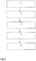
- FIG. 6 shows a flow chart for the assembly of a syringe 1.
- a prefilled body 2 is provided.
- the prefilled body comprises a body 2 filled with an injectable medicament 20 comprising ranibizumab, although other medicaments could be used in addition or instead, or a placebo solution could be used.
- a stopper 10 is arranged in the body 2 to form a variable volume chamber 18 and the outlet 12 is sealed with a sealing device 8.
- a plunger 4 is arranged in the body 2.
- the plunger 4 is dropped into the body 2. This may be by gravity alone, or the plunger may be placed into the body 2 using a machine or human and the body then oriented so that the plunger 4 falls into the body 2 until the plunger contact surface 22 makes contact with the stopper 10.
- a backstop 6 is coupled to the terminal flange 28 of the body.
- the backstop 6 and rod being arranged such that the rod shoulder 32 is located between the outlet end of the body and the backstop shoulder 34.
- Step 4 the syringe is sealed into a package and in Step 5 the package and its contents is sterilised in a terminal sterilisation process.
- the terminal sterilisation process may use known process such as an Ethylene Oxide or a Hydrogen Peroxide sterilisation process.
Abstract
Description
- The present invention relates to a syringe, particularly to a small volume syringe such as a syringe suitable for ophthalmic injections. The invention also extends to a method of assembling such a syringe.
- Many medicaments are delivered to a patient in a syringe from which the user can dispense the medicament. If medicament is delivered to a patient in a syringe it is often to enable the patient, or a caregiver, to inject the medicament. It is important for patient safety and medicament integrity that the syringe and the contents of that syringe are sufficiently sterile to avoid infection, or other, risks for patients. Sterilisation can be achieved by terminal sterilisation in which the assembled product, typically already in its associated packaging, is sterilised using heat or a sterilising gas.
- For small volume syringes, for example those for injections into the eye in which it is intended that less than about 0.1ml of liquid is to be injected, the sterilisation can pose difficulties that are not necessarily associated with larger syringes. Changes in pressure, internal or external to the syringe, can cause parts of the syringe to move unpredictably, which may alter sealing characteristics and potentially compromise sterility. Incorrect handling, including assembly, of the syringe can also pose risks to product sterility.
- The present invention provides a syringe, the syringe comprising a body, a stopper and a plunger, the body comprising an outlet at an outlet end and the stopper being arranged within the body such that a front surface of the stopper and the body define a variable volume chamber from which a fluid can be expelled though the outlet, the plunger comprising a plunger contact surface at a first end and a rod extending between the plunger contact surface and a rear portion, the plunger contact surface arranged to contact the stopper but not couple thereto, such that the plunger can be used to force the stopper towards the outlet end of the body, reducing the volume of the variable volume chamber, but not to move the stopper away from the outlet end.
- Providing a plunger which does not couple to the stopper reduces the chances for incorrect handling of the syringe as the plunger can be withdrawn from the syringe without movement of the stopper away from the outlet end. This prevents a user from accidentally moving the plunger (and therefore a stopper connected thereto) and causing non-sterile air (or other fluid) to be drawn into the syringe, or causing movement of the stopper to a non-sterile area. It has also been found that creating a connection between a plunger to a stopper during assembly, using for example a screwing action or a push-fit action, can distort the stopper in an unpredictable manner which may compromise the sealing and/or sterility of the final product, or may increase pressure in the variable volume chamber which could cause fluid leakage from the outlet end.
- The body of the syringe may be a substantially cylindrical shell, or may include a substantially cylindrical bore with a non-circular outer shape. The outlet end of the body includes an outlet through which a fluid housed within the variable volume chamber can be expelled as the volume of said chamber is reduced. The outlet may comprise a projection from the outlet end through which extends a channel having a smaller diameter than that of the variable volume chamber. The outlet may be adapted, for example via a luer lock type connection, for connection to a needle or other accessory such as a sealing device which is able to seal the variable volume chamber, but can be operated, or removed, to unseal the variable chamber and allow connection of the syringe to another accessory, such as a needle. Such a connection may be made directly between the syringe and accessory, or via the sealing device. The body extends along a first axis from the outlet end to a rear end.
- The body may be made from a plastic material or from glass, or from any other suitable material and may include indicia on a surface thereof to act as an injection guide.
- The stopper may be made from rubber, silicone or other suitable resiliently deformable material. The stopper provides a sealing function by defining the rear of the variable volume chamber with a fluid tight seal which also provides a sterility seal. The stopper may be substantially cylindrical and the stopper may include one or more circumferential ribs around an outer surface of the stopper, the stopper and ribs being dimensioned such that the ribs form a substantially fluid tight seal with an internal surface of the syringe body. The front surface of the stopper may be any suitable shape, for example substantially planar, or substantially conical. The stopper may be substantially solid or may include recesses. The rear surface of the stopper may include a substantially central recess which may be any shape provided the sealing function of the stopper is not compromised. Said central recess may be substantially cylindrical in shape or said central recess may include an initial bore having a first diameter, the initial bore leading from the rear surface into the stopper to an inner recess having a second diameter, the second diameter being larger than the first diameter. Such a central recess could be used to connect a plunger to the stopper using a snap fit feature in a known manner. Such a design allows a substantially standard stopper design to be used and this can reduce the parts cost for the syringe. Also, it is noted that removing material from the central portion of the stopper, where it is not needed for the stopper to function as required, reduces the stopper weight and reduces the amount of material needed to manufacture the stopper. The stopper may be substantially rotationally symmetric about an axis through the stopper.
- The plunger comprises a plunger contact surface and extending from that a rod extends from the plunger contact surface to a rear portion. The rear portion may include a user contact portion adapted to be contacted by a user during an injection event. The user contact portion may comprise a substantially disc shaped portion, the radius of the disc extending substantially perpendicular to the axis along which the rod extends. The user contact portion could be any suitable shape. The axis along which the rod extends may be the first axis, or may be substantially parallel with the first axis.
- The plunger contact surface is adapted to make contact with the rear surface of the stopper, but not couple thereto. The plunger contact surface may be substantially planar and may be substantially circular in shape. The plunger contact surface may be substantially circular with an outer diameter less than the internal diameter of the body. The diameter of the plunger contact surface may be substantially equal to the diameter of the rear surface of the stopper with which it is to make contact. The plunger contact surface may be adapted to present a substantially rotationally symmetrical surface to the rear surface of the stopper as this assists in providing a repeatable and evenly distributed force to the stopper during use which can help to prevent distortions. The plunger contact surface may not be planar and may comprise an annular contact surface to contact the stopper at or adjacent an out edge thereof. The plunger contact surface may comprise a plurality of arms which extend from the plunger rod to make contact with the stopper. The plunger contact surface may be substantially rotationally symmetrical in any of the above, or other, embodiments.
- The rod may have a round or cross-form cross-section. A cross-form cross section may be formed from ribs extending along at least part of the rod. The ribs may extend substantially parallel with the axis along which the rod extends. The cross-form cross section provides rigidity to the rod without significantly increasing manufacturing complexity.
- The rod may be manufactured from any suitable material, or combination of materials, and in one embodiment is made from a plastic material. The rod may be substantially rigid under expected use conditions. Although some flexing of the materials in the plunger is unavoidable in a bulk manufactured product, it is advantageous that the rod cannot flex significantly during use, particularly for low volume, accurate, injections as any flexing could lead to unpredictable dosing results.
- The syringe may include a backstop arranged at a rear portion of the body. The backstop may be removable from the syringe. If the syringe body includes terminal flanges at the end opposite the outlet end the backstop may be configured to substantially sandwich terminal flanges of the body as this prevent movement of the backstop in a direction parallel to the first axis.
- The rod may comprise at least one rod shoulder directed away from the outlet end and the backstop may include a backstop shoulder directed towards the outlet end to cooperate with the rod shoulder to substantially prevent movement of the rod away from the outlet end when the backstop shoulder and rod shoulder are in contact. Restriction of the movement of the rod away from the outlet end can help to maintain sterility during terminal sterilisation operations, or other operations in which the pressure within the variable volume chamber or outside the chamber may change. During such operations any gas trapped within the variable volume chamber, or bubbles that may form in a liquid therein, may change in volume and thereby cause the stopper to move. Movement of the stopper away from the outlet could result in the breaching of a sterility zone created by the stopper. This is particularly important for low volume syringes where there are much lower tolerances in the component sizes and less flexibility in the stopper. The term sterility zone as used herein is used to refer to the area within the syringe that is sealed by the stopper from access from either end of the syringe. This may be the area between a seal of the stopper, for example a circumferential ridge, closest to the outlet and a seal of the stopper, for example a circumferential ridge, furthest from the outlet. The distance between these two seals defines the sterility zone of the stopper since the stopper is installed into the syringe barrel in a sterile environment.
- As noted above, a terminal sterilisation process may be used to sterilise the complete article and such a process may use a known process such as an Ethylene Oxide or a Hydrogen Peroxide sterilisation process.
- The inclusion of one or more circumferential ribs on the stopper can alter the force required to cause the stopper to move from a stationary position and can also alter the sealing properties of the stopper. To further assist in maintaining sterility during the operations noted above the stopper may comprise at least a front circumferential rib and a rear circumferential rib and those ribs may be separated in a direction along the first axis by at least 3mm, by at least 3.5 mm, by at least 3.75mm or by 4mm or more. One or more additional ribs (for example 2, 3, 4 or 5 additional ribs, or between 1-10, 2-8, 3-6 or 4-5 additional ribs) may be arranged between the front and rear ribs. In one embodiment there are a total of three circumferential ribs.
- A stopper with such an enhanced sterility zone can also provide protection for the injectable medicament during a terminal sterilisation process. Some medicaments, example a biological medicament, could be damaged by exposure to Ethylene Oxide. More ribs on the stopper, or a greater distance between the front and rear ribs, can reduce the potential exposure of the medicament to the sterilising agent.
- The rod shoulder may be arranged within the external diameter of the rod, or may be arranged outside the external diameter of the rod. By providing a shoulder that extends beyond the external diameter of the rod, but still fits within the body, the shoulder can help to stabilise the movement of the rod within the body by reducing movement of the rod perpendicular to the first axis. The rod shoulder may comprise any suitable shoulder forming elements on the rod, but in one embodiment the rod shoulder comprises a substantially disc shaped portion on the rod.
- In one embodiment of the syringe, when arranged with the plunger contact surface in contact with the stopper and the variable volume chamber is at its intended maximum volume there is a clearance of no more than about 2mm between the rod shoulder and backstop shoulder. In some embodiments there is a clearance of less than about 1.5 mm and in some less than about 1mm. This distance is selected to substantially limit or prevent excessive rearward (away from the outlet end) movement of the stopper.
- In one embodiment the variable volume chamber has an internal diameter greater than 5mm or 6mm and less than 3mm or 4mm. The internal diameter may be between 3mm and 6mm, or between 4mm and 5mm. In another embodiment the syringe is dimensioned so as to have a nominal maximum fill volume of volume of between about 0.25ml and 0.75ml, or between 0.4ml and 0.6ml. The length of the body of the syringe may be less than 70mm, less than 60mm or less than 50mm. In one embodiment the length of the syringe body is between 45mm and 50mm, the internal diameter is between 4mm and 5mm and the fill volume is between 0.1ml and 0.3ml of liquid.
- In one embodiment, the syringe is suitable for ophthalmic injections, and as such has a suitably small volume. The syringe may be adapted for ophthalmic injections. The syringe may also be silicone free, or substantially silicone free, or may comprise a low level of silicone as lubricant. In one embodiment, the syringe may meet USP789.
- The variable volume chamber of the syringe may be filled with any suitable injectable liquid or medication, for example an injectable medicament. In one embodiment the variable volume chamber is filled with an injectable medicament comprising an active suitable for the treatment of an ocular disease. Examples of such ocular diseases include choroidal neovascularisation, age-related macular degeneration (both wet and dry forms), macular edema secondary to retinal vein occlusion (RVO) including both branch RVO (bRVO) and central RVO (cRVO), choroidal neovascularisation secondary to pathologic myopia (PM), diabetic macular edema (DME), diabetic retinopathy, and proliferative retinopathy. In one embodiment, the medicament comprises a biologic active. The biologic active may be an antibody (or fragment thereof) or a non-antibody protein. In one embodiment the medicament comprises a VEGF antagonist. Suitable VEGF antagonists include ranibizumab (Lucentis™), bevacizumab (Avastin™), aflibercept (Eylea™, also known as VEGF-Trap Eye), conbercept (KH902 from Chengdu Kanghong Biotechnologies Co. Ltd, described as FP3 in
WO2005/121176 , the contents of which are hereby incorporated by reference) and the related glycoform KH906 or pazopanib (from GlaxoSmithKline). - In one embodiment, the syringe is filled with between about 0.01ml and about 2ml (for example between about 0.05ml and about 1ml, between about 0.1ml and about 0.5ml) of an injectable medicament. Of course, typically a syringe is filled with more than the desired dose to be administered to the patient, to take into account wastage due to "dead space" within the syringe and needle. Thus, in one embodiment, the syringe is filled with a dosage volume (i.e. the volume of medicament intended for delivery to the patent) of between about 0.01ml and about 2ml (e.g. between about 0.05ml and about 1ml, between about 0.1ml and about 0.5ml) of an injectable medicament. For example, for Lucentis, the dosage volume is 0.05ml or 0.03ml (0.5mg or 0.3mg) of a 10mg/ml injectable medicament solution; for Eylea, the dosage volume is 0.05ml of a 40mg/ml injectable medicament solution.
- As noted above, when the syringe contains a medicament solution the outlet may be reversibly sealed to maintain sterility of the medicament. This sealing may be achieved through the use of a sealing device as is known in the art. For example the OVS™ system which is available from Vetter Pharma International GmbH. The sealing of the outlet should be such that that sterility of the contents of the variable volume chamber can be maintained until such time as the stopper is moved to breach the sterility seal or the outlet is unsealed.
- By providing a plunger that does not couple with the stopper a new method of assembly is made possible and so the invention further provides a method of assembling a syringe, the method comprising the steps of:
- i) providing a body and a stopper, the body comprising an outlet at an outlet end and the stopper being arranged within the body such that a front surface of the stopper and the body define a variable volume chamber from which a fluid can be expelled though the outlet, the outlet being releasably sealed and the variable volume chamber containing a medicament; and
- ii) providing a plunger comprising a plunger contact surface at a first end and a rod extending between the plunger contact surface and a rear portion and arranging the plunger contact surface and at least part of the plunger within the body without coupling the plunger to the stopper.
- The method may further comprise an additional step, step iii), of filling the variable volume chamber of the syringe, which may be filled with any suitable injectable medicament. In one embodiment the variable volume chamber is filled with an injectable medicament suitable for the treatment of an ocular disease. Examples of such ocular diseases include choroidal neovascularisation, age-related macular degeneration (both wet and dry forms), macular edema secondary to retinal vein occlusion (RVO) including both branch RVO (bRVO) and central RVO (cRVO), choroidal neovascularisation secondary to pathologic myopia (PM), diabetic macular edema (DME), diabetic retinopathy, and proliferative retinopathy. In one embodiment, the medicament comprises a biologic active. The biologic active may be an antibody (or fragment thereof) or a non-antibody protein. In one embodiment the medicament comprises a VEGF antagonist. Suitable VEGF antagonists include ranibizumab (Lucentis™), bevacizumab (Avastin™), aflibercept (Eylea™, also known as VEGF-Trap Eye), conbercept (KH902 from Chengdu Kanghong Biotechnologies Co. Ltd, described as FP3 in
WO2005/121176 , the contents of which are hereby incorporated by reference) and the related glycoform KH906 or pazopanib (from GlaxoSmithKline). - It should be noted that steps ii) and iii) above may be carried out in either order. Thus the method may comprise, in sequence, steps i), ii), iii) or steps i), iii), ii) or steps iii), i), ii).
- The method may further comprise a step iv) of packaging the assembled syringe in a substantially sealed package. The method may further comprise a terminal sterilisation step, step v), following packaging. The terminal sterilisation step may comprise known techniques such as Ethylene Oxide sterilisation of Hydrogen Peroxide sterilisation.
- The invention also extends to a sealed package containing a sterile pre-filled syringe substantially as described herein.
- If the rod comprises a rod shoulder as described above and the syringe includes a removable backstop as described the backstop may be coupled to the syringe body after the plunger has been arranged in the body and the rod shoulder is arranged between the outlet end and the backstop shoulder. By ensuring that the rod shoulder is arranged between the outlet end and the backstop shoulder when the backstop is coupled to the device a complex mechanism for enabling the movement of the rod shoulder past the backstop shoulder after coupling the backstop to the syringe is avoided.
- In one embodiment step i) and iii) are carried out in a sterile, or substantially sterile, environment. At some point between the filling step and the final assembly being sealed into packaging the syringe is removed from the sterile, or substantially sterile, environment. A terminal sterilisation step can then be conducted on the packaged product.
- In one embodiment of the method the plunger rod is dropped into the syringe body. This is a simple operation and makes use of gravity rather than any automated assembly equipment. This is made possible because the rod does not need to be manipulated or forced to couple with the stopper.
- The invention also provides a plunger suitable for use in the syringe or method described above.
- It should be understood that throughout this specification and in the claims that follow, unless the context requires otherwise, the word "comprise", or variations such as "comprises" or "comprising", implies the inclusion of the stated integer or step, or group of integers or steps. The term "comprising" encompasses "including" as well as "consisting" e.g. a composition "comprising" X may consist exclusively of X or may include something additional e.g. X + Y. It should also be understood that, unless not physically possible, features described in connection with one embodiment can be used alone, or in combination with one or more features described in connection with the same embodiment or one or more other embodiments. The term "about" in relation to a numerical value x is optional and means, for example, x +/- 10%.
- The invention will now be further described, by way of example only, with reference to the following drawings in which:
-
Figure 1 shows a side view of a syringe; -
Figure 2 shows a cross section of a top down view of a syringe; -
Figure 3 shows a view of a plunger; -
Figure 4 shows a cross section though a plunger; -
Figure 5 shows a stopper; and -
Figure 6 shows a flowchart of the assembly process. -
Figure 1 shows a view from a side of asyringe 1 comprising abody 2,plunger 4, backstop 6 and a sealing device 8. -
Figure 2 shows a cross section through thesyringe 1 ofFigure 1 from above. Thesyringe 1 is suitable for use in an ophthalmic injection. Thesyringe 1 comprises abody 2, astopper 10 and aplunger 4. Thesyringe 1 extends along a first axis A. Thebody 2 comprises anoutlet 12 at anoutlet end 14 and thestopper 10 is arranged within thebody 2 such that afront surface 16 of thestopper 10 and thebody 2 define avariable volume chamber 18. Thevariable volume chamber 18 contains aninjectable medicament 20 comprising ranibizumab. Theinjectable fluid 20 can be expelled though theoutlet 12 by movement of thestopper 10 towards theoutlet end 14 thereby reducing the volume of thevariable volume chamber 18. Theplunger 4 comprises aplunger contact surface 22 at afirst end 24 and arod 26 extending between theplunger contact surface 22 and arear portion 25. Theplunger contact surface 22 is arranged to contact thestopper 10 but not couple thereto, such that theplunger 4 can be used to move thestopper 10 towards the outlet end 14 of thebody 2. Such movement reduces the volume of thevariable volume chamber 18 and causes fluid therein to be expelled though the outlet. However, since theplunger 4 is not coupled to thestopper 10 it is not possible to use theplunger 4 to move thestopper 10 away from theoutlet end 14. - The
backstop 6 is attached to thebody 2 by coupling to aterminal flange 28 of thebody 2. Thebackstop 6 includessandwich portion 30 which is adapted to substantially sandwich at least some of theterminal flange 28 of thebody 2. Thebackstop 6 is adapted to be coupled to thebody 2 from the side by leaving one side of thebackstop 6 open so that thebackstop 6 can be fitted to thesyringe 2. - The
body 2 defines a substantiallycylindrical bore 36 which has a bore radius. Therod 26 comprises arod shoulder 32 directed away from theoutlet end 14. Therod shoulder 32 extends to a rod shoulder radius from the first axis A which is such that it slightly less than the bore radius so that the shoulder fits within thebore 36. Thebackstop 6 includes abackstop shoulder 34 directed towards theoutlet end 14. Theshoulders rod 26 away from theoutlet end 14 when thebackstop shoulder 34 androd shoulder 32 are in contact. Thebackstop shoulder 34 extends from outside the bore radius to a radius less than the rod shoulder radius so that therod shoulder 32 cannot pass thebackstop shoulder 34 by moving along the first axis A. In this case therod shoulder 32 is substantially disc, or ring, shaped and thebackstop shoulder 34 includes an arc around arear end 38 of thebody 2. - The
backstop 6 also includes twofinger projections 40 which extend in opposite directions away from thebody 2 substantially perpendicular to the first axis A to facilitate manual handling of thesyringe 1 during use. - In this example the syringe comprises a 0.5
ml body 2, that is a body with a notional maximum fill volume of about 0.5ml, filled with between about 0.1 and 0.3 ml of aninjectable medicament 20 comprising a 10mg/ml injectable solution comprising ranibizumab. Thesyringe body 2 has an internal diameter of about between about 4.5mm and 4.8mm, a length of between about 45mm and 50mm. - The
plunger 4 andstopper 10 will be described in more detail with reference to later figures. -
Figure 3 shows a perspective view of theplunger 4 ofFigure 1 showing theplunger contact surface 22 at thefirst end 24 of theplunger 4. Therod 26 extends from thefirst end 24 to therear portion 25. Therear portion 25 includes a disc shaped flange 42 to facilitate user handling of the device. The flange 42 provides a larger surface area for contact by the user than a bare end of therod 26. - The
rod 26 comprisesribs 44 which extend along therod 26, the ribs forming a cross-form cross section for therod 26 as shown in more detail in subsequent figures. Therod 26 comprises a disc shapedportion 46, the disc shapedportion 46 extending radially beyond theribs 44 and also forming therod shoulder 32. - The
ribs 44 may be substantially solid, or may includegaps 48. Thedisc portion 46 may be solid, or may include gaps 50.Gaps 48,50 may be used to facilitate gas flow within thebody 2 if necessary for sterilization, or other, purposes. -
Figure 4 shows a cross section though asyringe body 2 androd 26. Therod 26 includes fourlongitudinal ribs 44 and the angle between the ribs is 90°. -
Figure 5 shows a detailed view of astopper 10 showing a conical shapedfront surface 16 and threecircumferential ribs 52,54,56 around a substantially cylindrical body 58. The axial gap between the first rib 52 and the last rib 56 is about 3mm. Therear surface 60 of thestopper 10 includes a substantiallycentral recess 62. Thecentral recess 62 includes aninitial bore 64 having a first diameter. The initial bore 64 leading from therear surface 60 into thestopper 10 to an inner recess 66 having a second diameter, the second diameter being larger than the first diameter. -
Figure 6 shows a flow chart for the assembly of asyringe 1. In Step 1 aprefilled body 2 is provided. The prefilled body comprises abody 2 filled with aninjectable medicament 20 comprising ranibizumab, although other medicaments could be used in addition or instead, or a placebo solution could be used. Astopper 10 is arranged in thebody 2 to form avariable volume chamber 18 and theoutlet 12 is sealed with a sealing device 8. - In Step 2 a
plunger 4 is arranged in thebody 2. In one embodiment theplunger 4 is dropped into thebody 2. This may be by gravity alone, or the plunger may be placed into thebody 2 using a machine or human and the body then oriented so that theplunger 4 falls into thebody 2 until theplunger contact surface 22 makes contact with thestopper 10. - In Step 3 a
backstop 6 is coupled to theterminal flange 28 of the body. Thebackstop 6 and rod being arranged such that therod shoulder 32 is located between the outlet end of the body and thebackstop shoulder 34. - In
Step 4 the syringe is sealed into a package and inStep 5 the package and its contents is sterilised in a terminal sterilisation process. The terminal sterilisation process may use known process such as an Ethylene Oxide or a Hydrogen Peroxide sterilisation process. - It should be understood that the invention has been described above by way of example only and that modifications in detail can be made without departing from the scope of the claims.
Claims (12)
- A terminally sterilized, prefilled syringe for ophthalmic injections, the syringe comprising a body (2), a stopper (10) and a plunger (4), the body comprising an outlet (12) at an outlet end (14) and the stopper (10) being arranged within the body (2) such that a front surface (16) of the stopper (10) and the body (2) define a variable volume chamber (18) from which a fluid can be expelled though the outlet (12), the plunger (4) comprising a plunger contact surface (22) at a first end (24) and a rod (26) extending between the plunger contact surface (22) and a rear portion (25),
characterized in that- the syringe is filled with a dosage volume of between about 0.01 ml and about 2ml, and- the plunger contact surface (22) is arranged to contact the stopper (10) but not couple thereto, such that the plunger (4) can be used to force the stopper (10) towards the outlet end (14) of the body (2), reducing the volume of the variable volume chamber (18), but not to move the stopper (10) away from the outlet end (14), and- the syringe (1) includes a backstop (6) arranged at a rear portion of the body (2), the backstop (6) including a backstop shoulder (34) directed towards the outlet end (14) to cooperate with the rod shoulder (32) to substantially prevent movement of the plunger rod (26) away from the outlet end (14) when the backstop shoulder (34) and rod shoulder (32) are in contact, and- when the plunger contact surface (22) is in contact with the stopper (10) and the variable volume chamber (18) is at its intended maximum volume there is a clearance of no more than 2mm between the rod shoulder (32) and the backstop shoulder (34). - The syringe as claimed in claim 1, with a dosage volume of between about 0.05ml and about 1 ml.
- The syringe as claimed in claim 1 or 2, in which the plunger contact surface (22) is a substantially planar disc and the plunger contact surface (22) contacts a rear surface of the stopper (10).
- The syringe as claimed in any preceding claim, in which the rod shoulder (32) is arranged within the external diameter of the rod (26).
- The syringe as claimed in any preceding claim, in which the rod shoulder (32) comprises a substantially disc shaped portion of the rod (26).
- The syringe as claimed in any preceding claim, in which the stopper (10) has one or more circumferential ribs.
- The syringe as claimed in claim 6, in which the stopper (10) has a central recess.
- The syringe as claimed in any preceding claim, in which the syringe is silicone free or substantially silicone free.
- The syringe as claimed in any preceding claim, in which the syringe is filled with an injectable medicament comprising an active suitable for the treatment of an ocular disease.
- The syringe as claimed in claim 9, in which the medicament is a VEGF antagonist.
- The syringe as claimed in claim 10, in which the medicament is ranibizumab.
- The syringe as claimed in claim 10, in which the medicament is aflibercept.
Priority Applications (12)
| Application Number | Priority Date | Filing Date | Title |
|---|---|---|---|
| SI201331901T SI3536310T1 (en) | 2012-06-01 | 2013-05-30 | Syringe |
| PT201562741T PT3679922T (en) | 2012-06-01 | 2013-05-30 | Syringe |
| PL20198921T PL3777834T3 (en) | 2012-06-01 | 2013-05-30 | Syringe |
| PL19161189T PL3536310T3 (en) | 2012-06-01 | 2013-05-30 | Syringe |
| EP20198921.7A EP3777834B1 (en) | 2012-06-01 | 2013-05-30 | Syringe |
| PL20156274T PL3679922T3 (en) | 2012-06-01 | 2013-05-30 | Syringe |
| EP21164847.2A EP3858405B1 (en) | 2012-06-01 | 2013-05-30 | Syringe |
| DK20156274.1T DK3679922T3 (en) | 2012-06-01 | 2013-05-30 | Syringe |
| DK21164847.2T DK3858405T3 (en) | 2012-06-01 | 2013-05-30 | SYRINGE |
| EP20156274.1A EP3679922B1 (en) | 2012-06-01 | 2013-05-30 | Syringe |
| DK20198921.7T DK3777834T3 (en) | 2012-06-01 | 2013-05-30 | Syringe |
| HRP20211088TT HRP20211088T1 (en) | 2012-06-01 | 2021-07-08 | Syringe |
Applications Claiming Priority (3)
| Application Number | Priority Date | Filing Date | Title |
|---|---|---|---|
| EP12170628 | 2012-06-01 | ||
| PCT/EP2013/061215 WO2013178771A1 (en) | 2012-06-01 | 2013-05-30 | Syringe |
| EP13727570.7A EP2854762A1 (en) | 2012-06-01 | 2013-05-30 | Syringe |
Related Parent Applications (2)
| Application Number | Title | Priority Date | Filing Date |
|---|---|---|---|
| EP13727570.7A Division EP2854762A1 (en) | 2012-06-01 | 2013-05-30 | Syringe |
| PCT/EP2013/061215 Previously-Filed-Application WO2013178771A1 (en) | 2012-06-01 | 2013-05-30 | Syringe |
Related Child Applications (6)
| Application Number | Title | Priority Date | Filing Date |
|---|---|---|---|
| EP21164847.2A Division-Into EP3858405B1 (en) | 2012-06-01 | 2013-05-30 | Syringe |
| EP21164847.2A Division EP3858405B1 (en) | 2012-06-01 | 2013-05-30 | Syringe |
| EP20156274.1A Division EP3679922B1 (en) | 2012-06-01 | 2013-05-30 | Syringe |
| EP20156274.1A Division-Into EP3679922B1 (en) | 2012-06-01 | 2013-05-30 | Syringe |
| EP20198921.7A Division EP3777834B1 (en) | 2012-06-01 | 2013-05-30 | Syringe |
| EP20198921.7A Division-Into EP3777834B1 (en) | 2012-06-01 | 2013-05-30 | Syringe |
Publications (2)
| Publication Number | Publication Date |
|---|---|
| EP3536310A1 true EP3536310A1 (en) | 2019-09-11 |
| EP3536310B1 EP3536310B1 (en) | 2021-04-28 |
Family
ID=48577723
Family Applications (5)
| Application Number | Title | Priority Date | Filing Date |
|---|---|---|---|
| EP19161189.6A Active EP3536310B1 (en) | 2012-06-01 | 2013-05-30 | Syringe |
| EP20156274.1A Active EP3679922B1 (en) | 2012-06-01 | 2013-05-30 | Syringe |
| EP20198921.7A Active EP3777834B1 (en) | 2012-06-01 | 2013-05-30 | Syringe |
| EP13727570.7A Withdrawn EP2854762A1 (en) | 2012-06-01 | 2013-05-30 | Syringe |
| EP21164847.2A Active EP3858405B1 (en) | 2012-06-01 | 2013-05-30 | Syringe |
Family Applications After (4)
| Application Number | Title | Priority Date | Filing Date |
|---|---|---|---|
| EP20156274.1A Active EP3679922B1 (en) | 2012-06-01 | 2013-05-30 | Syringe |
| EP20198921.7A Active EP3777834B1 (en) | 2012-06-01 | 2013-05-30 | Syringe |
| EP13727570.7A Withdrawn EP2854762A1 (en) | 2012-06-01 | 2013-05-30 | Syringe |
| EP21164847.2A Active EP3858405B1 (en) | 2012-06-01 | 2013-05-30 | Syringe |
Country Status (36)
| Country | Link |
|---|---|
| US (8) | US20150105734A1 (en) |
| EP (5) | EP3536310B1 (en) |
| JP (8) | JP6781546B2 (en) |
| KR (5) | KR102386843B1 (en) |
| CN (1) | CN104780906A (en) |
| AR (1) | AR091817A1 (en) |
| AU (1) | AU2013269594C1 (en) |
| CA (2) | CA3126069A1 (en) |
| CL (1) | CL2014003251A1 (en) |
| CO (1) | CO7141462A2 (en) |
| CY (2) | CY1124375T1 (en) |
| DE (1) | DE202013012825U1 (en) |
| DK (4) | DK3536310T3 (en) |
| EA (1) | EA033161B1 (en) |
| ES (4) | ES2895406T3 (en) |
| GT (1) | GT201400279A (en) |
| HK (1) | HK1202816A1 (en) |
| HR (3) | HRP20220558T1 (en) |
| HU (2) | HUE055556T2 (en) |
| IL (3) | IL235882B (en) |
| IN (1) | IN2014DN09689A (en) |
| LT (3) | LT3679922T (en) |
| MA (2) | MA42648B1 (en) |
| MX (2) | MX2014014722A (en) |
| MY (1) | MY165727A (en) |
| NZ (1) | NZ702313A (en) |
| PE (1) | PE20142396A1 (en) |
| PH (1) | PH12014502675B1 (en) |
| PL (4) | PL3777834T3 (en) |
| PT (4) | PT3536310T (en) |
| SG (2) | SG10201900193YA (en) |
| SI (4) | SI3536310T1 (en) |
| TN (1) | TN2014000471A1 (en) |
| TW (1) | TW201402165A (en) |
| WO (1) | WO2013178771A1 (en) |
| ZA (1) | ZA201408019B (en) |
Cited By (1)
| Publication number | Priority date | Publication date | Assignee | Title |
|---|---|---|---|---|
| EP3679922B1 (en) | 2012-06-01 | 2021-07-28 | Novartis AG | Syringe |
Families Citing this family (48)
| Publication number | Priority date | Publication date | Assignee | Title |
|---|---|---|---|---|
| US11624115B2 (en) | 2010-05-12 | 2023-04-11 | Sio2 Medical Products, Inc. | Syringe with PECVD lubrication |
| US9878101B2 (en) | 2010-11-12 | 2018-01-30 | Sio2 Medical Products, Inc. | Cyclic olefin polymer vessels and vessel coating methods |
| CN103930595A (en) | 2011-11-11 | 2014-07-16 | Sio2医药产品公司 | Passivation, ph protective or lubricity coating for pharmaceutical package, coating process and apparatus |
| US11116695B2 (en) | 2011-11-11 | 2021-09-14 | Sio2 Medical Products, Inc. | Blood sample collection tube |
| JOP20200175A1 (en) | 2012-07-03 | 2017-06-16 | Novartis Ag | Syringe |
| US9764093B2 (en) | 2012-11-30 | 2017-09-19 | Sio2 Medical Products, Inc. | Controlling the uniformity of PECVD deposition |
| KR102336796B1 (en) | 2013-03-11 | 2021-12-10 | 에스아이오2 메디컬 프로덕츠, 인크. | Coated Packaging |
| EP3693493A1 (en) | 2014-03-28 | 2020-08-12 | SiO2 Medical Products, Inc. | Antistatic coatings for plastic vessels |
| AU2015260955B2 (en) * | 2014-05-12 | 2020-06-18 | Formycon Ag | Pre-filled plastic syringe containing a VEGF antagonist |
| US9840553B2 (en) | 2014-06-28 | 2017-12-12 | Kodiak Sciences Inc. | Dual PDGF/VEGF antagonists |
| MA41906A (en) | 2015-04-10 | 2018-02-13 | Dompe Farm Spa | EYE DROP DISTRIBUTION DEVICE |
| WO2017011895A1 (en) * | 2015-07-23 | 2017-01-26 | Luc Magne | Shroud for a dental syringe and combination thereof |
| US10800597B2 (en) * | 2015-09-11 | 2020-10-13 | New Product Development Concepts Llc | Telescoping syringe with one-way valve |
| CA3005692A1 (en) * | 2015-11-18 | 2017-05-26 | Formycon Ag | Pre-filled plastic syringe containing a vegf antagonist |
| RU2751510C2 (en) * | 2015-11-18 | 2021-07-14 | Сио2 Медикал Продактс, Инк. | Pharmaceutical packaging for ophthalmic formulations |
| EP3397276A4 (en) | 2015-12-30 | 2019-12-18 | Kodiak Sciences Inc. | Antibodies and conjugates thereof |
| US10369292B2 (en) * | 2016-01-15 | 2019-08-06 | W. L. Gore & Associates, Inc. | Syringe plunger assemblies |
| KR102288170B1 (en) * | 2016-04-08 | 2021-08-09 | 알레간 인코포레이티드 | Aspiration and injection device |
| ITUA20162072A1 (en) * | 2016-06-30 | 2017-12-30 | Platinum Corp Srl | Volume controlled dropper |
| CN109310815B (en) * | 2016-09-12 | 2022-06-10 | 魏民 | Drug delivery device |
| CA3050750A1 (en) * | 2017-02-17 | 2018-08-23 | Becton, Dickinson And Company | Syringe and plunger rod with stopper guide |
| US10799639B2 (en) * | 2017-03-03 | 2020-10-13 | Min Wei | Syringe type medication delivery device |
| EP3600456B1 (en) | 2017-03-27 | 2023-08-30 | Regeneron Pharmaceuticals, Inc. | Sterilisation method |
| JPWO2018180458A1 (en) | 2017-03-31 | 2020-02-06 | 武田薬品工業株式会社 | Syringe |
| AU2018262454A1 (en) | 2017-05-05 | 2019-10-10 | Novartis Ag | A syringe comprising a collapsible plunger |
| CN111148539A (en) * | 2017-09-29 | 2020-05-12 | 豪夫迈·罗氏有限公司 | Prefilled syringe and method of preparing a prefilled syringe |
| CN117065151A (en) | 2017-12-13 | 2023-11-17 | 里珍纳龙药品有限公司 | Device and method for accurate dose delivery |
| EP3735286A4 (en) | 2018-01-03 | 2021-03-03 | Irenix Medical, Inc. | Therapeutic agent delivery devices having integrated pain mitigation, and methods for using the same |
| US20210052816A1 (en) * | 2018-02-02 | 2021-02-25 | F. Hoffmann-La Roche Ag | Prefilled syringe and method of sterilizing a prefilled syringe |
| EP3773800A1 (en) * | 2018-04-09 | 2021-02-17 | SiO2 Medical Products, Inc. | Stretchable plunger assemblies |
| WO2019217927A1 (en) | 2018-05-10 | 2019-11-14 | Regeneron Pharmaceuticals, Inc. | High concentration vegf receptor fusion protein containing formulations |
| US20210196893A1 (en) * | 2018-05-24 | 2021-07-01 | Novartis Ag | Automatic Drug Delivery Device |
| US20210260300A1 (en) * | 2018-06-01 | 2021-08-26 | Sun Pharma Advanced Research Company Limited | An injection device |
| JP2019217105A (en) | 2018-06-21 | 2019-12-26 | 株式会社松風 | Injector |
| EP3886946A1 (en) | 2019-06-05 | 2021-10-06 | Regeneron Pharmaceuticals, Inc. | Devices and methods for precision dose delivery |
| USD920519S1 (en) | 2019-06-28 | 2021-05-25 | Oertli-Instrumente Ag | Medical instrument for eye surgical purposes |
| WO2021021925A1 (en) | 2019-07-29 | 2021-02-04 | Regeneron Pharmaceuticals, Inc. | Medical device packaging and related methods |
| USD906102S1 (en) | 2019-07-29 | 2020-12-29 | Regeneron Pharmaceuticals, Inc. | Packaging |
| EP4041312A4 (en) | 2019-10-10 | 2023-12-20 | Kodiak Sciences Inc. | Methods of treating an eye disorder |
| EP4079349A4 (en) | 2019-12-27 | 2023-01-11 | TERUMO Kabushiki Kaisha | Syringe-barrel grip, barrel assembly, and syringe |
| JPWO2021192637A1 (en) | 2020-03-24 | 2021-09-30 | ||
| MX2022014531A (en) | 2020-05-21 | 2023-03-03 | Coherus Biosciences Inc | Systems and methods for producing sterile injection devices. |
| USD961376S1 (en) | 2020-07-29 | 2022-08-23 | Regeneron Pharmaceuticals, Inc. | Packaging |
| USD961377S1 (en) | 2020-07-29 | 2022-08-23 | Regeneron Pharmaceuticals, Inc. | Packaging |
| KR20220085906A (en) * | 2020-12-15 | 2022-06-23 | 삼천당제약주식회사 | Syringe comprising ophthalmic formulation |
| WO2022217194A1 (en) * | 2021-04-06 | 2022-10-13 | Vitrean Inc. | A prefilled syringe containing a sterile ultraconcentrated hydrogel |
| WO2023097069A1 (en) * | 2021-11-29 | 2023-06-01 | Amgen Inc. | Plunger rod removal force method and fixture |
| WO2023153535A1 (en) * | 2022-02-09 | 2023-08-17 | 삼천당제약주식회사 | Syringe containing ophthalmic formulation |
Citations (9)
| Publication number | Priority date | Publication date | Assignee | Title |
|---|---|---|---|---|
| US4946441A (en) * | 1988-07-21 | 1990-08-07 | Maurice Laderoute | Limited use hypodermic syringe |
| US5181918A (en) * | 1990-08-10 | 1993-01-26 | Thera Patent Gmbh & Co. Kg Gesellschaft Fuer Industrielle Schutzrechte | Granules syringe |
| EP1488818A1 (en) * | 2002-03-15 | 2004-12-22 | Nippon Becton Dickinson Company, Ltd. | Prefilled syringe with plunger backward movement limiting mechanism |
| WO2005121176A1 (en) | 2004-06-08 | 2005-12-22 | Chengdu Kanghong Biotechnologies Co. Ltd | Angiogenesis-inhibiting chimeric protein and the use |
| US20060293270A1 (en) * | 2005-06-22 | 2006-12-28 | Adamis Anthony P | Methods and compositions for treating ocular disorders |
| WO2007035621A1 (en) * | 2005-09-16 | 2007-03-29 | (Osi) Eyetech, Inc. | Ophthalmic syringe |
| DE102008005938A1 (en) * | 2008-01-24 | 2009-07-30 | Arzneimittel Gmbh Apotheker Vetter & Co. Ravensburg | Pre-filled syringe for use in ophthalmology field, has piston rod with end coupled with stopper and opposite end, and aseptic secondary package e.g. cylindrical casing, with inner area provided for accommodation of syringe |
| EP2298392A1 (en) * | 2008-06-17 | 2011-03-23 | Denki Kagaku Kogyo Kabushiki Kaisha | Injector |
| US8075535B2 (en) * | 2003-05-26 | 2011-12-13 | Becton Dickinson France S.A. | Pre-filled syringe with anti-tamper cap |
Family Cites Families (92)
| Publication number | Priority date | Publication date | Assignee | Title |
|---|---|---|---|---|
| US1704924A (en) * | 1925-09-05 | 1929-03-12 | Cook Lab Inc | Syringe cartridge |
| US2236727A (en) * | 1939-01-07 | 1941-04-01 | Calbar Paint & Varnish Company | Plastic material dispenser |
| US2602447A (en) | 1947-12-20 | 1952-07-08 | Kollsman Paul | Device for hypodermic injection |
| US3148772A (en) * | 1962-09-18 | 1964-09-15 | Dentists Supply Co | Sterile surgical packaging |
| US3248950A (en) | 1964-05-25 | 1966-05-03 | Dow Chemical Co | Stop mechanism for pipette filling device |
| FR2348708A1 (en) | 1976-04-23 | 1977-11-18 | Becton Dickinson France | SYRINGE BULB AND METHOD OF USE |
| JPH0725953Y2 (en) * | 1988-03-17 | 1995-06-14 | 株式会社大協精工 | Syringe stopper |
| US5173258A (en) | 1989-10-11 | 1992-12-22 | American Sterilizer Company | Recirculation, vapor and humidity control in a sealable enclosure |
| US5380295A (en) | 1992-12-14 | 1995-01-10 | Mallinckrodt Medical, Inc. | Delivery apparatus with mechanism preventing rearward movement of a piston disposed therein |
| JPH0666689U (en) * | 1993-03-05 | 1994-09-20 | 浪華ゴム工業株式会社 | Syringe |
| JP3186422B2 (en) | 1993-05-14 | 2001-07-11 | 武田薬品工業株式会社 | Plastisol |
| US5405326A (en) | 1993-08-26 | 1995-04-11 | Habley Medical Technology Corporation | Disposable safety syringe with retractable shuttle for luer lock needle |
| US5795337A (en) * | 1994-02-14 | 1998-08-18 | Becton Dickinson And Company | Syringe assembly and syringe stopper |
| US5597530A (en) | 1994-08-18 | 1997-01-28 | Abbott Laboratories | Process for prefilling and terminally sterilizing syringes |
| US5688252A (en) | 1994-09-30 | 1997-11-18 | Takeda Chemical Industries, Ltd. | Syringe |
| US5667495A (en) | 1995-04-21 | 1997-09-16 | Becton Dickinson France S.A. | Backstop device for a syringe |
| US5607400A (en) * | 1995-05-19 | 1997-03-04 | Becton, Dickinson And Company | Pre-fillable syringe and stopper assembly therefor |
| US5607399A (en) | 1995-09-22 | 1997-03-04 | Becton, Dickinson And Company | Backstop device for a flangeless syringe |
| DE19613035B4 (en) * | 1996-03-19 | 2007-12-13 | Ferring Gmbh | System with a syringe and a handle |
| JPH09308689A (en) * | 1996-05-21 | 1997-12-02 | Nihon Medi Physics Co Ltd | Plunger having projection and syringe |
| DE19622283A1 (en) | 1996-05-23 | 1997-11-27 | Schering Ag | Process for the terminal sterilization of filled syringes |
| EP1787999B1 (en) | 1997-04-07 | 2010-08-04 | Genentech, Inc. | Anti-VEGF antibodies |
| JP3387775B2 (en) | 1997-05-22 | 2003-03-17 | 株式会社大協精工 | Sealing stopper for syringe and prefilled syringe |
| US6228324B1 (en) | 1997-11-28 | 2001-05-08 | Seikagaku Corporation | Sterilizing method for medical sterilization packaging and injection pack |
| JP3831505B2 (en) * | 1997-12-26 | 2006-10-11 | 生化学工業株式会社 | Sterilization method in medical sterilization packaging |
| US6189292B1 (en) * | 1998-03-13 | 2001-02-20 | Becton Dickinson And Company | Method and apparatus for manufacturing, filling and packaging medical devices and medical containers |
| WO1999055402A1 (en) | 1998-04-30 | 1999-11-04 | Abbott Laboratories | Syringe assembly |
| JP2000014779A (en) | 1998-07-02 | 2000-01-18 | Wada Kiyoutaro | Prefilled syringe |
| WO2001064266A1 (en) | 2000-03-02 | 2001-09-07 | Daikyo Seiko, Ltd. | Prefilled syringe assembly |
| US6608038B2 (en) | 2000-03-15 | 2003-08-19 | Novartis Ag | Methods and compositions for treatment of diabetes and related conditions via gene therapy |
| JP2001340455A (en) | 2000-05-31 | 2001-12-11 | Yoshino Kogyosho Co Ltd | Syringe container |
| JP4370045B2 (en) * | 2000-06-21 | 2009-11-25 | 大成化工株式会社 | Syringe |
| JP4626064B2 (en) | 2000-09-28 | 2011-02-02 | 生化学工業株式会社 | Syringe |
| JP2002177388A (en) | 2000-12-15 | 2002-06-25 | Daikyo Seiko Ltd | Pharmaceutical and medical pre-filled syringe |
| DE10103706A1 (en) | 2001-01-26 | 2002-08-14 | Aventis Behring Gmbh | Use of a hydrogen peroxide plasma sterilization process for the gentle sterilization of temperature-sensitive products |
| DE10122959A1 (en) | 2001-05-11 | 2002-11-21 | West Pharm Serv Drug Res Ltd | Method for producing a piston for a pharmaceutical syringe or a similar item includes a step in which surplus of the inert foil cap on the piston body is separated in a punching unit |
| JP2003052819A (en) | 2001-08-10 | 2003-02-25 | Seikagaku Kogyo Co Ltd | Drug filling syringe package and sterilization or bactericidal method for it |
| JP4256643B2 (en) * | 2001-12-27 | 2009-04-22 | 昭和薬品化工株式会社 | Cartridge syringe, cartridge, and ophthalmic syringe set including the syringe |
| US6830564B2 (en) * | 2002-01-24 | 2004-12-14 | Robin Scott Gray | Syringe and method of using |
| JP4566748B2 (en) * | 2002-10-11 | 2010-10-20 | ベクトン・ディキンソン・アンド・カンパニー | Cleaning syringe with backflow prevention function |
| WO2004075958A2 (en) | 2003-02-27 | 2004-09-10 | Baxter International Inc. | Piston assembly for syringe |
| US20060264967A1 (en) * | 2003-03-14 | 2006-11-23 | Ferreyro Roque H | Hydraulic device for the injection of bone cement in percutaneous vertebroplasty |
| JP2004313369A (en) | 2003-04-15 | 2004-11-11 | Menicon Co Ltd | Cartridge injector, cartridge and ophthalmological injector set with the injector |
| US20050129569A1 (en) | 2003-12-15 | 2005-06-16 | Becton, Dickinson And Company | Terminal sterilization of prefilled containers |
| WO2005070479A1 (en) * | 2003-12-26 | 2005-08-04 | Wet Trust Japan Co., Ltd. | Portable jetting/filling device |
| US20050148947A1 (en) | 2003-12-30 | 2005-07-07 | Advanced Medical Optics, Inc. | Cannula locking device |
| CA2556718A1 (en) | 2004-02-18 | 2005-08-25 | Mcgill University | A device for injecting a viscous material into a hard tissue |
| DE102004009919B4 (en) | 2004-02-20 | 2007-02-08 | Schott Ag | Syringe, especially for medical applications |
| JP4759232B2 (en) * | 2004-07-02 | 2011-08-31 | テルモ株式会社 | Method for manufacturing packaged prefilled syringe |
| PT1802334E (en) | 2004-10-21 | 2012-11-28 | Genentech Inc | Method for treating intraocular neovascular diseases |
| EP1888150A1 (en) * | 2005-05-31 | 2008-02-20 | Baxter International Inc. | Polypropylene hollow barrel with sliding coated rubber piston |
| JP4584057B2 (en) | 2005-07-08 | 2010-11-17 | テルモ株式会社 | Prefilled syringe |
| DE102005037962A1 (en) | 2005-08-11 | 2007-02-15 | Arzneimittel Gmbh Apotheker Vetter & Co. Ravensburg | syringe |
| JP4848784B2 (en) * | 2006-02-02 | 2011-12-28 | ニプロ株式会社 | Plunger and syringe and prefilled syringe using the same |
| EP1818069B1 (en) | 2006-02-14 | 2008-09-03 | Gerresheimer Bünde GmbH | Process for manufacturing syringes to be pre-filled |
| DK2944306T3 (en) * | 2006-06-16 | 2021-03-08 | Regeneron Pharma | Suitable VEGF antagonist formulations for intravitreal administration |
| JP4131001B2 (en) | 2006-07-28 | 2008-08-13 | 大成化工株式会社 | Metering device |
| ATE554813T1 (en) | 2006-08-30 | 2012-05-15 | Hoffmann La Roche | INJECTION DEVICE WITH SIMPLIFIED PLUG RETENTION |
| US8038656B2 (en) | 2006-09-29 | 2011-10-18 | Tyco Healthcare Group Lp | Detachable plunger rod syringe |
| US20080114306A1 (en) | 2006-11-03 | 2008-05-15 | Bare Rex O | Small volume syringe with writing portion |
| WO2008077155A1 (en) | 2006-12-21 | 2008-06-26 | Genentech, Inc. | Sterilization of objects containing biological molecules |
| US7972302B2 (en) | 2007-06-12 | 2011-07-05 | Becton, Dickinson And Company | Syringe with disabling mechanism |
| ES2376761T3 (en) | 2007-07-31 | 2012-03-16 | Al.Chi.Mi.A. S.R.L. | Method for performing a device for ophthalmic treatments |
| WO2009030976A1 (en) | 2007-09-03 | 2009-03-12 | Becton Dickinson France | Medical device and smooth coating therefor |
| US9295776B2 (en) * | 2008-04-11 | 2016-03-29 | Medtronic Minimed, Inc. | Reservoir plunger head systems and methods |
| JP5163882B2 (en) | 2008-05-27 | 2013-03-13 | 澁谷工業株式会社 | Sterilization method |
| CN101640886B (en) | 2008-07-29 | 2012-04-25 | 上海华为技术有限公司 | Authentication method, re-authentication method and communication device |
| WO2010024209A1 (en) | 2008-08-25 | 2010-03-04 | 電気化学工業株式会社 | Syringe |
| CN201263820Y (en) * | 2008-09-02 | 2009-07-01 | 甘肃成纪生物药业有限公司 | Double-chamber cartridge bottle powder injection pre-filling syringe |
| US20100087796A1 (en) * | 2008-10-03 | 2010-04-08 | Reichert, Inc. | Method For Controlling A Pump Drive |
| JP2012505162A (en) * | 2008-10-09 | 2012-03-01 | ワラタ ファーマシューティカルズ, インコーポレイテッド | Use of scyllo-inositol for treating macular degeneration related disorders |
| US8221353B2 (en) | 2008-10-21 | 2012-07-17 | KMG Pharma, Inc | Intravitreal injection device and system |
| US7678078B1 (en) | 2008-10-21 | 2010-03-16 | KMG Pharma LLC | Intravitreal injection device, system and method |
| TWI543790B (en) | 2008-12-03 | 2016-08-01 | Denka Company Ltd | To syringe |
| WO2010081838A2 (en) * | 2009-01-14 | 2010-07-22 | Novartis Ag | Sterile prefilled container |
| CN102341138B (en) * | 2009-03-09 | 2013-06-19 | 泰尔茂株式会社 | Gasket and syringe |
| USH2251H1 (en) * | 2009-05-12 | 2011-01-04 | The United States Of America As Represented By The United States Department Of Veterans Affairs | Method of preparing multiple doses of a pharmaceutical solution from a single-dose |
| AR078060A1 (en) | 2009-07-14 | 2011-10-12 | Novartis Ag | DECONTAMINATION OF CONTAINER SURFACE PREVIOUSLY FILLED IN SECONDARY PACKAGING |
| JP5431051B2 (en) | 2009-07-17 | 2014-03-05 | 株式会社大協精工 | A small-capacity piston for a syringe and a plunger to which the piston is attached |
| CN102725012B (en) | 2009-10-29 | 2016-01-06 | W.L.戈尔及同仁股份有限公司 | The syringe plug of coating intumescent PTFE |
| EP2554205B1 (en) * | 2010-03-30 | 2020-04-22 | Terumo Kabushiki Kaisha | Medical device with slideable coating, and syringe |
| US9408746B2 (en) | 2010-03-31 | 2016-08-09 | Ocuject, Llc | Device and method for intraocular drug delivery |
| WO2011125475A1 (en) | 2010-03-31 | 2011-10-13 | テルモ株式会社 | Syringe |
| US8754862B2 (en) * | 2010-07-11 | 2014-06-17 | Lester F. Ludwig | Sequential classification recognition of gesture primitives and window-based parameter smoothing for high dimensional touchpad (HDTP) user interfaces |
| JP2012045046A (en) | 2010-08-24 | 2012-03-08 | Gc Corp | Dental syringe |
| US20120078219A1 (en) | 2010-09-29 | 2012-03-29 | Tyco Healthcare Group Lp | Syringe Assembly |
| FR2966044B1 (en) | 2010-10-18 | 2012-11-02 | Sanofi Pasteur | METHOD FOR CONDITIONING A VACCINE CONTAINING AN ALUMINUM ADJUVANT |
| WO2012117837A1 (en) | 2011-03-01 | 2012-09-07 | テルモ株式会社 | Syringe and syringe assembly |
| US20120271245A1 (en) * | 2011-04-21 | 2012-10-25 | Achan Jr Leonard | Malleable stopper for a syringe |
| MY165727A (en) | 2012-06-01 | 2018-04-20 | Novartis Ag | Syringe |
| JOP20200175A1 (en) | 2012-07-03 | 2017-06-16 | Novartis Ag | Syringe |
| MX2019015792A (en) | 2017-06-29 | 2020-02-07 | Regeneron Pharma | Devices and methods for overfilling drug containers. |
-
2013
- 2013-05-30 MY MYPI2014003096A patent/MY165727A/en unknown
- 2013-05-30 KR KR1020217024698A patent/KR102386843B1/en active IP Right Grant
- 2013-05-30 DK DK19161189.6T patent/DK3536310T3/en active
- 2013-05-30 MA MA42648A patent/MA42648B1/en unknown
- 2013-05-30 PT PT191611896T patent/PT3536310T/en unknown
- 2013-05-30 HU HUE19161189A patent/HUE055556T2/en unknown
- 2013-05-30 KR KR1020227012006A patent/KR102453181B1/en active IP Right Grant
- 2013-05-30 ES ES20156274T patent/ES2895406T3/en active Active
- 2013-05-30 SI SI201331901T patent/SI3536310T1/en unknown
- 2013-05-30 NZ NZ702313A patent/NZ702313A/en unknown
- 2013-05-30 HU HUE20156274A patent/HUE055994T2/en unknown
- 2013-05-30 EP EP19161189.6A patent/EP3536310B1/en active Active
- 2013-05-30 EP EP20156274.1A patent/EP3679922B1/en active Active
- 2013-05-30 ES ES20198921T patent/ES2913198T3/en active Active
- 2013-05-30 PL PL20198921T patent/PL3777834T3/en unknown
- 2013-05-30 DK DK20156274.1T patent/DK3679922T3/en active
- 2013-05-30 WO PCT/EP2013/061215 patent/WO2013178771A1/en active Application Filing
- 2013-05-30 HR HRP20220558TT patent/HRP20220558T1/en unknown
- 2013-05-30 PE PE2014002246A patent/PE20142396A1/en active IP Right Grant
- 2013-05-30 ES ES21164847T patent/ES2948322T3/en active Active
- 2013-05-30 SI SI201332047T patent/SI3858405T1/en unknown
- 2013-05-30 PL PL21164847.2T patent/PL3858405T3/en unknown
- 2013-05-30 MX MX2014014722A patent/MX2014014722A/en unknown
- 2013-05-30 SI SI201331983T patent/SI3777834T1/en unknown
- 2013-05-30 CA CA3126069A patent/CA3126069A1/en not_active Abandoned
- 2013-05-30 EA EA201492261A patent/EA033161B1/en not_active IP Right Cessation
- 2013-05-30 DK DK20198921.7T patent/DK3777834T3/en active
- 2013-05-30 SG SG10201900193YA patent/SG10201900193YA/en unknown
- 2013-05-30 JP JP2015514516A patent/JP6781546B2/en active Active
- 2013-05-30 DK DK21164847.2T patent/DK3858405T3/en active
- 2013-05-30 AR ARP130101908A patent/AR091817A1/en active IP Right Grant
- 2013-05-30 ES ES19161189T patent/ES2881196T3/en active Active
- 2013-05-30 MA MA37599A patent/MA37599A1/en unknown
- 2013-05-30 LT LTEP20156274.1T patent/LT3679922T/en unknown
- 2013-05-30 PT PT201562741T patent/PT3679922T/en unknown
- 2013-05-30 US US14/403,801 patent/US20150105734A1/en not_active Abandoned
- 2013-05-30 PT PT201989217T patent/PT3777834T/en unknown
- 2013-05-30 SI SI201331933T patent/SI3679922T1/en unknown
- 2013-05-30 AU AU2013269594A patent/AU2013269594C1/en active Active
- 2013-05-30 IN IN9689DEN2014 patent/IN2014DN09689A/en unknown
- 2013-05-30 LT LTEP19161189.6T patent/LT3536310T/en unknown
- 2013-05-30 EP EP20198921.7A patent/EP3777834B1/en active Active
- 2013-05-30 KR KR1020217008444A patent/KR102288287B1/en active IP Right Grant
- 2013-05-30 KR KR1020207035156A patent/KR102232708B1/en active IP Right Grant
- 2013-05-30 KR KR1020147033198A patent/KR20150021924A/en active Application Filing
- 2013-05-30 PL PL19161189T patent/PL3536310T3/en unknown
- 2013-05-30 EP EP13727570.7A patent/EP2854762A1/en not_active Withdrawn
- 2013-05-30 EP EP21164847.2A patent/EP3858405B1/en active Active
- 2013-05-30 PT PT211648472T patent/PT3858405T/en unknown
- 2013-05-30 CA CA2875193A patent/CA2875193A1/en not_active Abandoned
- 2013-05-30 PL PL20156274T patent/PL3679922T3/en unknown
- 2013-05-30 LT LTEP20198921.7T patent/LT3777834T/en unknown
- 2013-05-30 CN CN201380028946.2A patent/CN104780906A/en active Pending
- 2013-05-30 HR HRP20211572TT patent/HRP20211572T1/en unknown
- 2013-05-30 DE DE202013012825.9U patent/DE202013012825U1/en not_active Expired - Lifetime
- 2013-05-30 SG SG11201407241QA patent/SG11201407241QA/en unknown
- 2013-05-31 TW TW102119459A patent/TW201402165A/en unknown
-
2014
- 2014-11-03 ZA ZA2014/08019A patent/ZA201408019B/en unknown
- 2014-11-07 TN TN2014000471A patent/TN2014000471A1/en unknown
- 2014-11-24 IL IL235882A patent/IL235882B/en active IP Right Grant
- 2014-11-27 CO CO14261546A patent/CO7141462A2/en unknown
- 2014-11-28 CL CL2014003251A patent/CL2014003251A1/en unknown
- 2014-11-28 PH PH12014502675A patent/PH12014502675B1/en unknown
- 2014-12-01 MX MX2020005315A patent/MX2020005315A/en unknown
- 2014-12-01 GT GT201400279A patent/GT201400279A/en unknown
-
2015
- 2015-04-10 HK HK15103519.9A patent/HK1202816A1/en unknown
-
2018
- 2018-11-05 JP JP2018208290A patent/JP6920269B2/en active Active
-
2019
- 2019-05-10 US US16/409,291 patent/US11103644B2/en active Active
-
2020
- 2020-02-14 US US16/791,505 patent/US11147925B2/en active Active
- 2020-02-26 IL IL272913A patent/IL272913B2/en unknown
- 2020-03-06 US US16/811,430 patent/US11110226B2/en active Active
- 2020-03-12 JP JP2020043041A patent/JP7026991B2/en active Active
-
2021
- 2021-02-12 US US17/174,981 patent/US11179521B2/en active Active
- 2021-04-05 JP JP2021064330A patent/JP7075521B2/en active Active
- 2021-06-01 US US17/335,684 patent/US11185635B2/en active Active
- 2021-07-08 HR HRP20211088TT patent/HRP20211088T1/en unknown
- 2021-07-26 CY CY20211100667T patent/CY1124375T1/en unknown
- 2021-08-16 JP JP2021132366A patent/JP7042954B2/en active Active
- 2021-08-25 JP JP2021137017A patent/JP2021184827A/en not_active Withdrawn
- 2021-10-13 US US17/500,174 patent/US20220031952A1/en not_active Abandoned
- 2021-10-14 CY CY20211100891T patent/CY1124585T1/en unknown
-
2022
- 2022-02-15 JP JP2022021374A patent/JP2022081491A/en not_active Withdrawn
- 2022-08-22 JP JP2022131761A patent/JP2022166261A/en not_active Withdrawn
- 2022-08-31 IL IL296105A patent/IL296105B2/en unknown
- 2022-12-09 US US18/063,918 patent/US20230113993A1/en active Pending
Patent Citations (9)
| Publication number | Priority date | Publication date | Assignee | Title |
|---|---|---|---|---|
| US4946441A (en) * | 1988-07-21 | 1990-08-07 | Maurice Laderoute | Limited use hypodermic syringe |
| US5181918A (en) * | 1990-08-10 | 1993-01-26 | Thera Patent Gmbh & Co. Kg Gesellschaft Fuer Industrielle Schutzrechte | Granules syringe |
| EP1488818A1 (en) * | 2002-03-15 | 2004-12-22 | Nippon Becton Dickinson Company, Ltd. | Prefilled syringe with plunger backward movement limiting mechanism |
| US8075535B2 (en) * | 2003-05-26 | 2011-12-13 | Becton Dickinson France S.A. | Pre-filled syringe with anti-tamper cap |
| WO2005121176A1 (en) | 2004-06-08 | 2005-12-22 | Chengdu Kanghong Biotechnologies Co. Ltd | Angiogenesis-inhibiting chimeric protein and the use |
| US20060293270A1 (en) * | 2005-06-22 | 2006-12-28 | Adamis Anthony P | Methods and compositions for treating ocular disorders |
| WO2007035621A1 (en) * | 2005-09-16 | 2007-03-29 | (Osi) Eyetech, Inc. | Ophthalmic syringe |
| DE102008005938A1 (en) * | 2008-01-24 | 2009-07-30 | Arzneimittel Gmbh Apotheker Vetter & Co. Ravensburg | Pre-filled syringe for use in ophthalmology field, has piston rod with end coupled with stopper and opposite end, and aseptic secondary package e.g. cylindrical casing, with inner area provided for accommodation of syringe |
| EP2298392A1 (en) * | 2008-06-17 | 2011-03-23 | Denki Kagaku Kogyo Kabushiki Kaisha | Injector |
Cited By (2)
| Publication number | Priority date | Publication date | Assignee | Title |
|---|---|---|---|---|
| EP3679922B1 (en) | 2012-06-01 | 2021-07-28 | Novartis AG | Syringe |
| EP3777834B1 (en) | 2012-06-01 | 2022-02-16 | Novartis AG | Syringe |
Also Published As
Similar Documents
| Publication | Publication Date | Title |
|---|---|---|
| US20230113993A1 (en) | Syringe |
Legal Events
| Date | Code | Title | Description |
|---|---|---|---|
| PUAI | Public reference made under article 153(3) epc to a published international application that has entered the european phase |
Free format text: ORIGINAL CODE: 0009012 |
|
| STAA | Information on the status of an ep patent application or granted ep patent |
Free format text: STATUS: THE APPLICATION HAS BEEN PUBLISHED |
|
| AC | Divisional application: reference to earlier application |
Ref document number: 2854762 Country of ref document: EP Kind code of ref document: P |
|
| AK | Designated contracting states |
Kind code of ref document: A1 Designated state(s): AL AT BE BG CH CY CZ DE DK EE ES FI FR GB GR HR HU IE IS IT LI LT LU LV MC MK MT NL NO PL PT RO RS SE SI SK SM TR |
|
| AX | Request for extension of the european patent |
Extension state: BA ME |
|
| STAA | Information on the status of an ep patent application or granted ep patent |
Free format text: STATUS: REQUEST FOR EXAMINATION WAS MADE |
|
| 17P | Request for examination filed |
Effective date: 20200311 |
|
| RBV | Designated contracting states (corrected) |
Designated state(s): AL AT BE BG CH CY CZ DE DK EE ES FI FR GB GR HR HU IE IS IT LI LT LU LV MC MK MT NL NO PL PT RO RS SE SI SK SM TR |
|
| GRAP | Despatch of communication of intention to grant a patent |
Free format text: ORIGINAL CODE: EPIDOSNIGR1 |
|
| STAA | Information on the status of an ep patent application or granted ep patent |
Free format text: STATUS: GRANT OF PATENT IS INTENDED |
|
| INTG | Intention to grant announced |
Effective date: 20200602 |
|
| REG | Reference to a national code |
Ref country code: HK Ref legal event code: DE Ref document number: 40009701 Country of ref document: HK |
|
| RAX | Requested extension states of the european patent have changed |
Extension state: BA Payment date: 20200813 Extension state: ME Payment date: 20200813 |
|
| GRAJ | Information related to disapproval of communication of intention to grant by the applicant or resumption of examination proceedings by the epo deleted |
Free format text: ORIGINAL CODE: EPIDOSDIGR1 |
|
| STAA | Information on the status of an ep patent application or granted ep patent |
Free format text: STATUS: REQUEST FOR EXAMINATION WAS MADE |
|
| GRAP | Despatch of communication of intention to grant a patent |
Free format text: ORIGINAL CODE: EPIDOSNIGR1 |
|
| STAA | Information on the status of an ep patent application or granted ep patent |
Free format text: STATUS: GRANT OF PATENT IS INTENDED |
|
| INTC | Intention to grant announced (deleted) | ||
| INTG | Intention to grant announced |
Effective date: 20201112 |
|
| GRAS | Grant fee paid |
Free format text: ORIGINAL CODE: EPIDOSNIGR3 |
|
| GRAA | (expected) grant |
Free format text: ORIGINAL CODE: 0009210 |
|
| STAA | Information on the status of an ep patent application or granted ep patent |
Free format text: STATUS: THE PATENT HAS BEEN GRANTED |
|
| AC | Divisional application: reference to earlier application |
Ref document number: 2854762 Country of ref document: EP Kind code of ref document: P |
|
| AK | Designated contracting states |
Kind code of ref document: B1 Designated state(s): AL AT BE BG CH CY CZ DE DK EE ES FI FR GB GR HR HU IE IS IT LI LT LU LV MC MK MT NL NO PL PT RO RS SE SI SK SM TR |
|
| AX | Request for extension of the european patent |
Extension state: BA ME |
|
| REG | Reference to a national code |
Ref country code: GB Ref legal event code: FG4D |
|
| REG | Reference to a national code |
Ref country code: CH Ref legal event code: EP |
|
| REG | Reference to a national code |
Ref country code: DE Ref legal event code: R096 Ref document number: 602013077264 Country of ref document: DE |
|
| REG | Reference to a national code |
Ref country code: AT Ref legal event code: REF Ref document number: 1386309 Country of ref document: AT Kind code of ref document: T Effective date: 20210515 |
|
| REG | Reference to a national code |
Ref country code: IE Ref legal event code: FG4D |
|
| REG | Reference to a national code |
Ref country code: HR Ref legal event code: TUEP Ref document number: P20211088T Country of ref document: HR |
|
| REG | Reference to a national code |
Ref country code: FI Ref legal event code: FGE |
|
| REG | Reference to a national code |
Ref country code: PT Ref legal event code: SC4A Ref document number: 3536310 Country of ref document: PT Date of ref document: 20210714 Kind code of ref document: T Free format text: AVAILABILITY OF NATIONAL TRANSLATION Effective date: 20210708 |
|
| REG | Reference to a national code |
Ref country code: DK Ref legal event code: T3 Effective date: 20210713 |
|
| REG | Reference to a national code |
Ref country code: NL Ref legal event code: FP |
|
| REG | Reference to a national code |
Ref country code: RO Ref legal event code: EPE |
|
| REG | Reference to a national code |
Ref country code: SE Ref legal event code: TRGR |
|
| REG | Reference to a national code |
Ref country code: GR Ref legal event code: EP Ref document number: 20210401964 Country of ref document: GR Effective date: 20210813 |
|
| REG | Reference to a national code |
Ref country code: EE Ref legal event code: FG4A Ref document number: E021076 Country of ref document: EE Effective date: 20210708 |
|
| REG | Reference to a national code |
Ref country code: SK Ref legal event code: T3 Ref document number: E 37643 Country of ref document: SK |
|
| REG | Reference to a national code |
Ref country code: NO Ref legal event code: T2 Effective date: 20210428 |
|
| REG | Reference to a national code |
Ref country code: HR Ref legal event code: ODRP Ref document number: P20211088T Country of ref document: HR Payment date: 20210708 Year of fee payment: 9 |
|
| REG | Reference to a national code |
Ref country code: HR Ref legal event code: T1PR Ref document number: P20211088 Country of ref document: HR |
|
| REG | Reference to a national code |
Ref country code: ES Ref legal event code: FG2A Ref document number: 2881196 Country of ref document: ES Kind code of ref document: T3 Effective date: 20211129 |
|
| PG25 | Lapsed in a contracting state [announced via postgrant information from national office to epo] |
Ref country code: RS Free format text: LAPSE BECAUSE OF FAILURE TO SUBMIT A TRANSLATION OF THE DESCRIPTION OR TO PAY THE FEE WITHIN THE PRESCRIBED TIME-LIMIT Effective date: 20210428 |
|
| REG | Reference to a national code |
Ref country code: HU Ref legal event code: AG4A Ref document number: E055556 Country of ref document: HU |
|
| REG | Reference to a national code |
Ref country code: DE Ref legal event code: R026 Ref document number: 602013077264 Country of ref document: DE |
|
| PLBI | Opposition filed |
Free format text: ORIGINAL CODE: 0009260 |
|
| PG25 | Lapsed in a contracting state [announced via postgrant information from national office to epo] |
Ref country code: MC Free format text: LAPSE BECAUSE OF FAILURE TO SUBMIT A TRANSLATION OF THE DESCRIPTION OR TO PAY THE FEE WITHIN THE PRESCRIBED TIME-LIMIT Effective date: 20210428 Ref country code: SM Free format text: LAPSE BECAUSE OF FAILURE TO SUBMIT A TRANSLATION OF THE DESCRIPTION OR TO PAY THE FEE WITHIN THE PRESCRIBED TIME-LIMIT Effective date: 20210428 |
|
| PLBI | Opposition filed |
Free format text: ORIGINAL CODE: 0009260 |
|
| PLAX | Notice of opposition and request to file observation + time limit sent |
Free format text: ORIGINAL CODE: EPIDOSNOBS2 |
|
| REG | Reference to a national code |
Ref country code: FI Ref legal event code: MDE Opponent name: WESS, WOLFGANG Ref country code: FI Ref legal event code: MDE Opponent name: HAMM&WITTKOPP PATENTANWAELTE PARTMBB Ref country code: FI Ref legal event code: MDE Opponent name: KEIL & SCHAAFHAUSEN PATENTANWAELTE PARTGMBB |
|
| 26 | Opposition filed |
Opponent name: KEIL & SCHAAFHAUSEN PATENTANWAELTE PARTGMBB Effective date: 20220126 |
|
| REG | Reference to a national code |
Ref country code: FI Ref legal event code: MDE Opponent name: WESS, WOLFGANG Ref country code: FI Ref legal event code: MDE Opponent name: HAMM&WITTKOPP PATENTANWAELTE PARTMBB Ref country code: FI Ref legal event code: MDE Opponent name: KEIL & SCHAAFHAUSEN PATENTANWAELTE PARTGMBB |
|
| 26 | Opposition filed |
Opponent name: WESS, WOLFGANG Effective date: 20220128 Opponent name: HAMM&WITTKOPP PATENTANWAELTE PARTMBB Effective date: 20220128 |
|
| PG25 | Lapsed in a contracting state [announced via postgrant information from national office to epo] |
Ref country code: AL Free format text: LAPSE BECAUSE OF FAILURE TO SUBMIT A TRANSLATION OF THE DESCRIPTION OR TO PAY THE FEE WITHIN THE PRESCRIBED TIME-LIMIT Effective date: 20210428 |
|
| PLBB | Reply of patent proprietor to notice(s) of opposition received |
Free format text: ORIGINAL CODE: EPIDOSNOBS3 |
|
| REG | Reference to a national code |
Ref country code: HR Ref legal event code: ODRP Ref document number: P20211088 Country of ref document: HR Payment date: 20220527 Year of fee payment: 10 |
|
| PGFP | Annual fee paid to national office [announced via postgrant information from national office to epo] |
Ref country code: RO Payment date: 20220517 Year of fee payment: 10 Ref country code: NO Payment date: 20220510 Year of fee payment: 10 Ref country code: HU Payment date: 20220430 Year of fee payment: 10 Ref country code: HR Payment date: 20220527 Year of fee payment: 10 Ref country code: EE Payment date: 20220421 Year of fee payment: 10 Ref country code: BG Payment date: 20220511 Year of fee payment: 10 Ref country code: LT Payment date: 20220526 Year of fee payment: 10 |
|
| REG | Reference to a national code |
Ref country code: GB Ref legal event code: S72Z Free format text: CLAIM LODGED; CLAIM FOR REVOCATION LODGED AT THE PATENTS COURT ON 23 MARCH 2022 (HP-2022-000008) |
|
| PGFP | Annual fee paid to national office [announced via postgrant information from national office to epo] |
Ref country code: LV Payment date: 20220420 Year of fee payment: 10 Ref country code: FI Payment date: 20220509 Year of fee payment: 10 |
|
| PGFP | Annual fee paid to national office [announced via postgrant information from national office to epo] |
Ref country code: MT Payment date: 20220525 Year of fee payment: 10 Ref country code: IS Payment date: 20220428 Year of fee payment: 10 |
|
| PGFP | Annual fee paid to national office [announced via postgrant information from national office to epo] |
Ref country code: CY Payment date: 20220421 Year of fee payment: 10 |
|
| P01 | Opt-out of the competence of the unified patent court (upc) registered |
Effective date: 20230514 |
|
| PGFP | Annual fee paid to national office [announced via postgrant information from national office to epo] |
Ref country code: NL Payment date: 20230426 Year of fee payment: 11 Ref country code: LU Payment date: 20230512 Year of fee payment: 11 |
|
| PGFP | Annual fee paid to national office [announced via postgrant information from national office to epo] |
Ref country code: PT Payment date: 20230601 Year of fee payment: 11 Ref country code: IT Payment date: 20230427 Year of fee payment: 11 Ref country code: IE Payment date: 20230425 Year of fee payment: 11 Ref country code: FR Payment date: 20230421 Year of fee payment: 11 Ref country code: ES Payment date: 20230605 Year of fee payment: 11 Ref country code: DK Payment date: 20230511 Year of fee payment: 11 Ref country code: DE Payment date: 20230418 Year of fee payment: 11 Ref country code: CZ Payment date: 20230517 Year of fee payment: 11 Ref country code: CH Payment date: 20230605 Year of fee payment: 11 |
|
| PGFP | Annual fee paid to national office [announced via postgrant information from national office to epo] |
Ref country code: TR Payment date: 20230530 Year of fee payment: 11 Ref country code: SK Payment date: 20230425 Year of fee payment: 11 Ref country code: SI Payment date: 20230426 Year of fee payment: 11 Ref country code: SE Payment date: 20230426 Year of fee payment: 11 Ref country code: PL Payment date: 20230421 Year of fee payment: 11 Ref country code: GR Payment date: 20230427 Year of fee payment: 11 Ref country code: AT Payment date: 20230425 Year of fee payment: 11 |
|
| REG | Reference to a national code |
Ref country code: GB Ref legal event code: S72Z Free format text: CLAIM FOR REVOCATION LODGED AT THE PATENTS COURT ON 23 MARCH 2022 (HP-2022-000008). PATENT REVOKED BY THE CONSENT ORDER OF HIGH COURT DATED 10 AUGUST 2023. |
|
| PGFP | Annual fee paid to national office [announced via postgrant information from national office to epo] |
Ref country code: BE Payment date: 20230427 Year of fee payment: 11 |
|
| PG25 | Lapsed in a contracting state [announced via postgrant information from national office to epo] |
Ref country code: GB Free format text: THE PATENT HAS BEEN ANNULLED BY A DECISION OF A NATIONAL AUTHORITY Effective date: 20230810 |
|
| PGFP | Annual fee paid to national office [announced via postgrant information from national office to epo] |
Ref country code: GB Payment date: 20230420 Year of fee payment: 11 |
|
| REG | Reference to a national code |
Ref country code: AT Ref legal event code: UEP Ref document number: 1386309 Country of ref document: AT Kind code of ref document: T Effective date: 20210428 |
|
| REG | Reference to a national code |
Ref country code: HR Ref legal event code: PBON Ref document number: P20211088 Country of ref document: HR Effective date: 20230530 |
|
| REG | Reference to a national code |
Ref country code: EE Ref legal event code: MM4A Ref document number: E021076 Country of ref document: EE Effective date: 20230531 |
|
| PLBP | Opposition withdrawn |
Free format text: ORIGINAL CODE: 0009264 |
|
| REG | Reference to a national code |
Ref country code: NO Ref legal event code: MMEP Ref country code: LT Ref legal event code: MM4D Effective date: 20230530 |
|
| PG25 | Lapsed in a contracting state [announced via postgrant information from national office to epo] |
Ref country code: RO Free format text: LAPSE BECAUSE OF NON-PAYMENT OF DUE FEES Effective date: 20230530 Ref country code: NO Free format text: LAPSE BECAUSE OF NON-PAYMENT OF DUE FEES Effective date: 20230531 Ref country code: LV Free format text: LAPSE BECAUSE OF NON-PAYMENT OF DUE FEES Effective date: 20230530 Ref country code: LT Free format text: LAPSE BECAUSE OF NON-PAYMENT OF DUE FEES Effective date: 20230530 Ref country code: HU Free format text: LAPSE BECAUSE OF NON-PAYMENT OF DUE FEES Effective date: 20230531 Ref country code: HR Free format text: LAPSE BECAUSE OF NON-PAYMENT OF DUE FEES Effective date: 20230530 Ref country code: FI Free format text: LAPSE BECAUSE OF NON-PAYMENT OF DUE FEES Effective date: 20230530 Ref country code: EE Free format text: LAPSE BECAUSE OF NON-PAYMENT OF DUE FEES Effective date: 20230531 Ref country code: CY Free format text: LAPSE BECAUSE OF NON-PAYMENT OF DUE FEES Effective date: 20230530 |
|
| PLBP | Opposition withdrawn |
Free format text: ORIGINAL CODE: 0009264 |