EP3536234B1 - Improvements in or relating to video monitoring - Google Patents
Improvements in or relating to video monitoring Download PDFInfo
- Publication number
- EP3536234B1 EP3536234B1 EP19158085.1A EP19158085A EP3536234B1 EP 3536234 B1 EP3536234 B1 EP 3536234B1 EP 19158085 A EP19158085 A EP 19158085A EP 3536234 B1 EP3536234 B1 EP 3536234B1
- Authority
- EP
- European Patent Office
- Prior art keywords
- subject
- vital signs
- video image
- detected
- displaying
- Prior art date
- Legal status (The legal status is an assumption and is not a legal conclusion. Google has not performed a legal analysis and makes no representation as to the accuracy of the status listed.)
- Active
Links
Images



Classifications
-
- G—PHYSICS
- G06—COMPUTING OR CALCULATING; COUNTING
- G06T—IMAGE DATA PROCESSING OR GENERATION, IN GENERAL
- G06T7/00—Image analysis
- G06T7/0002—Inspection of images, e.g. flaw detection
- G06T7/0012—Biomedical image inspection
-
- A—HUMAN NECESSITIES
- A61—MEDICAL OR VETERINARY SCIENCE; HYGIENE
- A61B—DIAGNOSIS; SURGERY; IDENTIFICATION
- A61B5/00—Measuring for diagnostic purposes; Identification of persons
- A61B5/02—Detecting, measuring or recording for evaluating the cardiovascular system, e.g. pulse, heart rate, blood pressure or blood flow
- A61B5/024—Measuring pulse rate or heart rate
- A61B5/02416—Measuring pulse rate or heart rate using photoplethysmograph signals, e.g. generated by infrared radiation
-
- A—HUMAN NECESSITIES
- A61—MEDICAL OR VETERINARY SCIENCE; HYGIENE
- A61B—DIAGNOSIS; SURGERY; IDENTIFICATION
- A61B5/00—Measuring for diagnostic purposes; Identification of persons
- A61B5/103—Measuring devices for testing the shape, pattern, colour, size or movement of the body or parts thereof, for diagnostic purposes
- A61B5/11—Measuring movement of the entire body or parts thereof, e.g. head or hand tremor or mobility of a limb
- A61B5/1126—Measuring movement of the entire body or parts thereof, e.g. head or hand tremor or mobility of a limb using a particular sensing technique
- A61B5/1128—Measuring movement of the entire body or parts thereof, e.g. head or hand tremor or mobility of a limb using a particular sensing technique using image analysis
-
- A—HUMAN NECESSITIES
- A61—MEDICAL OR VETERINARY SCIENCE; HYGIENE
- A61B—DIAGNOSIS; SURGERY; IDENTIFICATION
- A61B5/00—Measuring for diagnostic purposes; Identification of persons
- A61B5/68—Arrangements of detecting, measuring or recording means, e.g. sensors, in relation to patient
- A61B5/6887—Arrangements of detecting, measuring or recording means, e.g. sensors, in relation to patient mounted on external non-worn devices, e.g. non-medical devices
- A61B5/6889—Rooms
-
- G—PHYSICS
- G06—COMPUTING OR CALCULATING; COUNTING
- G06F—ELECTRIC DIGITAL DATA PROCESSING
- G06F3/00—Input arrangements for transferring data to be processed into a form capable of being handled by the computer; Output arrangements for transferring data from processing unit to output unit, e.g. interface arrangements
- G06F3/01—Input arrangements or combined input and output arrangements for interaction between user and computer
- G06F3/048—Interaction techniques based on graphical user interfaces [GUI]
- G06F3/0481—Interaction techniques based on graphical user interfaces [GUI] based on specific properties of the displayed interaction object or a metaphor-based environment, e.g. interaction with desktop elements like windows or icons, or assisted by a cursor's changing behaviour or appearance
- G06F3/04817—Interaction techniques based on graphical user interfaces [GUI] based on specific properties of the displayed interaction object or a metaphor-based environment, e.g. interaction with desktop elements like windows or icons, or assisted by a cursor's changing behaviour or appearance using icons
-
- G—PHYSICS
- G06—COMPUTING OR CALCULATING; COUNTING
- G06F—ELECTRIC DIGITAL DATA PROCESSING
- G06F3/00—Input arrangements for transferring data to be processed into a form capable of being handled by the computer; Output arrangements for transferring data from processing unit to output unit, e.g. interface arrangements
- G06F3/01—Input arrangements or combined input and output arrangements for interaction between user and computer
- G06F3/048—Interaction techniques based on graphical user interfaces [GUI]
- G06F3/0481—Interaction techniques based on graphical user interfaces [GUI] based on specific properties of the displayed interaction object or a metaphor-based environment, e.g. interaction with desktop elements like windows or icons, or assisted by a cursor's changing behaviour or appearance
- G06F3/0482—Interaction with lists of selectable items, e.g. menus
-
- G—PHYSICS
- G06—COMPUTING OR CALCULATING; COUNTING
- G06T—IMAGE DATA PROCESSING OR GENERATION, IN GENERAL
- G06T7/00—Image analysis
- G06T7/20—Analysis of motion
-
- H—ELECTRICITY
- H04—ELECTRIC COMMUNICATION TECHNIQUE
- H04N—PICTORIAL COMMUNICATION, e.g. TELEVISION
- H04N7/00—Television systems
- H04N7/18—Closed-circuit television [CCTV] systems, i.e. systems in which the video signal is not broadcast
- H04N7/183—Closed-circuit television [CCTV] systems, i.e. systems in which the video signal is not broadcast for receiving images from a single remote source
-
- G—PHYSICS
- G06—COMPUTING OR CALCULATING; COUNTING
- G06T—IMAGE DATA PROCESSING OR GENERATION, IN GENERAL
- G06T2200/00—Indexing scheme for image data processing or generation, in general
- G06T2200/24—Indexing scheme for image data processing or generation, in general involving graphical user interfaces [GUIs]
-
- G—PHYSICS
- G06—COMPUTING OR CALCULATING; COUNTING
- G06T—IMAGE DATA PROCESSING OR GENERATION, IN GENERAL
- G06T2207/00—Indexing scheme for image analysis or image enhancement
- G06T2207/10—Image acquisition modality
- G06T2207/10016—Video; Image sequence
-
- G—PHYSICS
- G06—COMPUTING OR CALCULATING; COUNTING
- G06T—IMAGE DATA PROCESSING OR GENERATION, IN GENERAL
- G06T2207/00—Indexing scheme for image analysis or image enhancement
- G06T2207/20—Special algorithmic details
- G06T2207/20092—Interactive image processing based on input by user
- G06T2207/20104—Interactive definition of region of interest [ROI]
-
- G—PHYSICS
- G06—COMPUTING OR CALCULATING; COUNTING
- G06T—IMAGE DATA PROCESSING OR GENERATION, IN GENERAL
- G06T2207/00—Indexing scheme for image analysis or image enhancement
- G06T2207/30—Subject of image; Context of image processing
- G06T2207/30196—Human being; Person
-
- G—PHYSICS
- G06—COMPUTING OR CALCULATING; COUNTING
- G06T—IMAGE DATA PROCESSING OR GENERATION, IN GENERAL
- G06T2207/00—Indexing scheme for image analysis or image enhancement
- G06T2207/30—Subject of image; Context of image processing
- G06T2207/30232—Surveillance
Definitions
- the present invention relates to a method and apparatus for monitoring a human or animal subject, and in particular a subject within an enclosed area, e.g. a room such as a secure room.
- a subject is in an enclosed environment, such as a room in a hospital, secure room in a prison or hospital, or even a home environment, where a duty of care is placed on an authority responsible for the subject.
- Such monitoring may comprise regular, scheduled visual checks by a member of staff and/or continuous video monitoring of the subject in the room. While such monitoring can be effective, difficulties can arise with the subject's health changing quickly between scheduled checks, or with a lack of movement of the subject being misinterpreted.
- a subject who is lying still on a bed or on the floor may be resting or asleep, or may have a suffered a deterioration in health.
- Subjects who are under the influence of alcohol or drugs or suffering a mental condition may behave in ways which are abnormal and difficult for staff observing them to interpret correctly. It would therefore be useful to have a way of monitoring the subject which provides an indication of their health.
- Another common problem with such video image analysis is finding and tracking the subject in the video image.
- the human body is naturally deformable and the orientation of the subject with respect to camera's view point can vary significantly. Also the subjects may be still, in which case motion-based detection and tracking can fail, or may move significantly or in unpredictable ways, which can be difficult for feature-based techniques.
- illumination may vary between daylight and artificial light and secure rooms are sometimes lit with visible artificial light and are sometimes completely dark, with infrared being the only illumination available.
- Other sources of regular or irregular movement may also appear in the scene being monitored - e.g. insects flying in, ventilation fans, domestic appliances
- the arrangement of the video monitoring apparatus itself may cause difficulty for the video analysis.
- the video camera or cameras have to be positioned out of reach of the subject, normally high in a corner of the room. This means that the view of the subject tends to compressed by perspective and the subject is only a relatively small fraction of the field of view.
- the monitoring has to continue in the dark (when the subject is asleep), it is normal to use a monochrome infrared camera, which means that techniques relying on full colour images do not work.
- US-A1-2017/0007185 discloses a non-contact PPGi based method of detecting physiological signals involving detecting areas of skin in a video image by colour analysis, defining these areas as regions of interest if they are above a size threshold, judging movement of the subject by measuring movement of the centroid of the region of interest, and measuring PPGi signals if the region of interest is not moving.
- EP-A1-3207862 discloses a PPGi based monitoring method involving automatic selection of regions of interest, with user input permitted, and filtering various sources of interference.
- US-A1-2017/0224256 discloses a PPGi based monitoring method in which regions of interest can be adjusted based on tracking recognised image features on the subject.
- the present invention provides a method of monitoring a human or animal subject as defined by the appended claims.
- the method therefore provides for a verification step that the subject is in the image and that the subject is still, such that the vital signs measurement can be expected to be valid, or moving, meaning that the vital signs estimation may not be valid but that the subject is alive.
- the method inherently includes some form of status and identity check of the subject.
- the vital signs measurement is more reliable. For example, the method would not be confused by the presence of a fan or some other powered equipment generating periodic movement or periodic intensity variations.
- the step of determining whether the subject is still comprises displaying a video image of the subject to the user and asking the user to input whether or not the subject is still.
- the graphical user interface displays a request for the user to input their determination of whether the subject is still or moving.
- the subject may be automatically detected in the image, for example using a conventional single shot detection (SSD) algorithm, with corresponding automatic detection of whether the subject is still or moving.
- Movement may be automatically detected by using a technique such as that in the paper by Pisani et al mentioned above or other techniques such as calculating the differences in pixels between consecutive frames or tracking the movements of features in the images.
- the step of determining whether regions of the video image from which vital signs are detected are not on the subject comprises displaying a video image of the subject with an indication in the displayed image of where vital signs are detected.
- regions of interest used by the algorithm for detecting vital signs may be displayed in a visually distinguishable way, for example by outlining them or by changing their intensity or colour.
- icons may be overlaid over the entire regions of interest, or over their centre.
- the regions of interest may be displayed as shapes, such as regular geometric shapes, e.g. circles, rectangles, ovals, ellipses, whose centres indicate the centre of mass of a set of highly correlated vital sign signals.
- the regions of interest may be displayed as shapes whose centres indicate the centre of mass of a set of highly correlated vital sign signals, weighted by the strength of the signals.
- the size of the shapes e.g. where the shapes are circles, their radii, may indicate the spatial distribution of the signals.
- the graphical user interface displays a request to the user to input the result of a user determination of whether the regions of the image from which vital signs are being detected are on the subject or not, or more particularly whether there all such regions are on the subject.
- the method may further comprise: displaying a menu of selectable steps, one of said selectable steps being to take an observation of the vital signs of the subject; and upon selection of the step of taking an observation of the vital signs of the subject, performing the steps of determining if the subject is still and if all areas producing vital signs signals are on the subject.
- the method is extended to monitor a plurality of subjects simultaneously.
- the graphical user interface may display an icon corresponding to each subject or room, with the user being able to select an individual icon and thus access the monitoring for that subject or room.
- the icons may simply indicate the room or subject, or may inherently include an indication of the status of the subject or room. For example, they may indicate whether or not the room is occupied by a human or animal subject, they may indicate a current estimate of the status of the subject, such as moving or not moving, and optionally may indicate a health status based on vital signs detection.
- Another aspect of the invention provides apparatus for monitoring a subject in a room, the apparatus comprising a video camera configured to capture a video image sequence of the subject in the room, a data processor configured to automatically process the video image as specified above, and a display for displaying the output, the apparatus executing the method above.
- the video camera may be a standard digital video camera so that the video image sequence is a conventional frame sequence with each frame comprising a spatial array of pixels of varying intensities and/or colours.
- the camera may be monochrome or may be a colour camera providing pixel intensities in the red, green and blue channels.
- the video image sequence may be time-windowed, i.e. divided into batches of successive frames for processing, and the steps of subject tracking, movement measurement and vital signs estimation are conducted on the time windows.
- the time windows may be of, for example, 900 frames, corresponding to 1 minute at 15 frames per second. Successive time windows may be overlapping, for example by 0.9 seconds.
- the invention may also be embodied in a computer program for processing a captured video image sequence in accordance with the invention and for outputting the results on a display.
- a computer program may run on a general purpose computer of conventional type.
- FIG. 1 schematically illustrates an apparatus in accordance with an embodiment of the invention being used to monitor a subject 3 in a room 1a.
- the room 1a can be a secure room such as a police or prison cell or some other detention facility, or could be a room in a hospital or other care facility such as a care home, sheltered accommodation or the subject's own home. It may be one of plural rooms being monitored as indicated by the neighbouring room 1b.
- the subject 3 is monitored by a video camera 5 a whose output is processed by a video signal processor 7 and the results of the analysis are displayed on a display 9 which is visible to staff of the facility.
- the video signal processor 7 receives inputs from the video cameras 5b in other rooms.
- the video signal processor 7 may be a dedicated signal processor or a programmed general purpose computer.
- the rooms may be naturally lit or may be artificially illuminated using a visible light source 11 or infrared light source 13.
- the video camera 5a,b is a standard digital video camera outputting video data in the form of a sequence of image frames, each frame being a pixel array of intensities in red, green, blue channels.
- the red, green and blue channels also give a response in the infrared range allowing the production of an infra-red (IR) image useful when the room is dark.
- Video cameras of this type typically output the signal at fifteen frames per second, though of course different frame rates are possible.
- the display 9 preferably displays the video image of the rooms and also displays information regarding the health or safety of the subject 3. This information is preferably:
- Staff monitoring the subject by way of the display 9 can therefore tell at any given time whether the subject is considered safe, for example because they are moving or because the vital signs are being detected and are in a physiologically normal range, or whether the system is unable to detect vital signs and safe movement is detected (and for how long that situation has persisted), or that no vital signs and no movement is present, in which case an alert is generated instructing staff to check the subject. If the lack of vital signs detection persists for more than a configurable amount of time an audio and/or visual alert may be generated to call on staff to check the subject. Alerts can include a range of electronic notification methods including automated telephone message, paper, SMS, as well as indication on the display 9 with the alert containing the condition and location of the subject and the condition being alerted.
- any of the published techniques based on analysing the image to detect a PPG signal may be used, e.g. those in WO-A2-2013/027027 , WO-A-2011/021128 and WO-A1-2015/049150 or in "Distance PPG: robust non-contact vital signs monitoring using a camera” by Mayank Kumarthe which are incorporated herein by reference. These are typically based on detecting a photoplethysmogram signal and movements in video images of the subject and deriving the heart rate and breathing rate from this PPG signal and body movements associated with breathing.
- the vital signs estimation runs in a separate parallel process 304 on the processor 7 under the overall video monitoring process 300. Its output is provided to the user interface process 302. As these estimation techniques are known to the person skilled in the art they are not described in detail here.
- the processor 7 does not have enough signal data to estimate vital signs (for example because the system is starting from initialisation or because the subject has been moving grossly, which means that estimation would be required to be re-initialised), then a display message "acquiring vital signs" is shown on the display 9 in respect of that subject. If the process 304 is estimating vital signs then it is assessed whether these are valid current heart rate and breathing rate measurements. By valid, is meant within the normal physiological range for this vital sign. If there is no valid current heart rate or breathing rate then it is assessed whether there is a relatively recent, for example, less than 5 seconds old, valid heart rate or breathing rate estimate, and if so, then this will be used as the current heart rate or breathing rate for display via the user interface process 302.
- the system may also record and provide a summary report of the vital signs and any alerts raised during predetermined periods, e.g. daily, weekly, monthly, and/or for the complete period the subject is in the room.
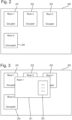
- FIG. 2 schematically illustrates one screen of the graphical user interface 200 displayed on the display 9 by the user interface process 302.
- individual icons 201, 202, 203, 204 are displayed, each representing one of the rooms 1a, 1b...being monitored.
- each of the icons includes a label indicating which room it represents, and an indication of whether the room is occupied or unoccupied.
- the indication of whether the room is occupied or unoccupied can be based on a sensor in the room, a user-controlled setting or analysis of camera frames to determine whether a person is present in the room.
- Figure 3 schematically illustrates a screen of the user interface 200 which is displayed on the display 9 in response to selection of one of the icons 201-204 of Figure 2 .
- an icon 301 is displayed overlying the display of Figure 2 , the icon 301 presenting a list of selectable options 303 for the user to choose.
- the selectable options include:
- One of the options in the list 303 is to "take an observation", meaning to display to the user the vital signs of the subject as obtained by the vital signs analysis process 304.
- Figure 5 illustrates the process flow in response to selection of the "take an observation” option in Figure 3 .
- step 501 In response to the user selecting the "take an observation” option in step 501, it is checked whether or not the vital signs analysis process 304 is currently returning a vital signs measurement. If not, then the message "acquiring" will be displayed on the display 9 in step 502.
- step 503 a determination will be made in step 503 as to whether the subject is still.
- This may be manual or automatic.
- the graphical user interface 200 displays the question “Is the subject still?" and offers clickable icons for the user to choose “Yes” or “No”. The user makes the determination based on the displayed video image 302 and clicks the appropriate icon.
- a standard algorithm for detecting a human subject in an image such as the single shot detection algorithm is used, together with a standard algorithm for detecting movement of the subject such as calculating the differences in pixel values between frames over time, or using optical flow to track features in the frames and measuring the velocity with which the features move.
- step 503 If the subject is not determined in step 503 as being still, it will mean that a vital signs measurement cannot be taken or will not be accurate and so the process is abandoned in step 504. Alternatively, if the subject is determined as still, then a determination is made in step 505 of whether the vital signs being detected by the vital signs analysis process 304 are all coming from regions of the image which are on the subject 3. This is performed based on manual input.
- the processor 7 displays in the video image 302 the regions of the image from which vital signs are being detected by the vital signs analysis process 304. This may be by outlining them, or changing their intensity or colour, or displaying an icon overlying such regions.
- Figure 6 shows an example display from a manual embodiment in which circles 60 indicate the regions from which vital signs are being detected.
- heart rate is being measured from the skin on the face of the subject 3
- breathing rate is being measured from movements of the chest and abdomen.
- the processor also displays a question to the user asking whether any of the displayed indicators are not on the subject and provides for clickable icons for the user to indicate "Yes" or "No" answers.
- step 504. If any of the regions from which vital signs are being detected are not on the subject, this means that there are extraneous signal sources and the vital signs estimation is not reliable. Consequently the process abandons in step 504. Alternatively, if the only regions from which vital signs are detected are on the subject, it can be assumed that the vital signs measurements are meaningful and they are displayed on the display 9 in step 506.
- the vital signs analysis process 304 may automatically find regions of interest in the video image from which vital signs are to be assessed, or may use user input to guide the selection of regions of interest.
- An example of an automated method is to calculate the "centre of mass" of a set of highly correlated vital sign signals found by the vital signs analysis process, weighted by the strength of the signals. The region of interest is then displayed as a circle whose radius indicates how spatially distributed these signals are.
- An example of a user-guided selection method is to require the user to first define the region of the image from which vital signs are to be measured (for example by drawing a rectangle over the chest region from which breathing rate is to be measured, or by drawing a rectangle over the whole of the subject's body).
- the invention may be embodied in a signal processing method, or in a signal processing apparatus which may be constructed as dedicated hardware or by means of a programmed general purpose computer or programmable digital signal processor.
- the invention also extends to a computer program for executing the method.
Landscapes
- Health & Medical Sciences (AREA)
- Engineering & Computer Science (AREA)
- Life Sciences & Earth Sciences (AREA)
- Physics & Mathematics (AREA)
- Theoretical Computer Science (AREA)
- Medical Informatics (AREA)
- General Health & Medical Sciences (AREA)
- Molecular Biology (AREA)
- Animal Behavior & Ethology (AREA)
- Public Health (AREA)
- Surgery (AREA)
- Biophysics (AREA)
- Heart & Thoracic Surgery (AREA)
- Veterinary Medicine (AREA)
- Biomedical Technology (AREA)
- Pathology (AREA)
- General Physics & Mathematics (AREA)
- General Engineering & Computer Science (AREA)
- Computer Vision & Pattern Recognition (AREA)
- Physiology (AREA)
- Cardiology (AREA)
- Radiology & Medical Imaging (AREA)
- Nuclear Medicine, Radiotherapy & Molecular Imaging (AREA)
- Multimedia (AREA)
- Human Computer Interaction (AREA)
- Dentistry (AREA)
- Oral & Maxillofacial Surgery (AREA)
- Quality & Reliability (AREA)
- Signal Processing (AREA)
- Measuring And Recording Apparatus For Diagnosis (AREA)
- Measurement Of The Respiration, Hearing Ability, Form, And Blood Characteristics Of Living Organisms (AREA)
Description
- The present invention relates to a method and apparatus for monitoring a human or animal subject, and in particular a subject within an enclosed area, e.g. a room such as a secure room.
- There are many situations where a subject is in an enclosed environment, such as a room in a hospital, secure room in a prison or hospital, or even a home environment, where a duty of care is placed on an authority responsible for the subject. To comply with such duty of care requirements, it is conventional to monitor subjects in such environments. Such monitoring may comprise regular, scheduled visual checks by a member of staff and/or continuous video monitoring of the subject in the room. While such monitoring can be effective, difficulties can arise with the subject's health changing quickly between scheduled checks, or with a lack of movement of the subject being misinterpreted. For example, a subject who is lying still on a bed or on the floor may be resting or asleep, or may have a suffered a deterioration in health. Subjects who are under the influence of alcohol or drugs or suffering a mental condition may behave in ways which are abnormal and difficult for staff observing them to interpret correctly. It would therefore be useful to have a way of monitoring the subject which provides an indication of their health.
- Monitoring of vital signs offers the possibility of mitigating some of these problems, but traditional contact-based vital signs sensors are restrictive and inconvenient, and some subjects may not co-operate with their use. Recent developments demonstrating that vital signs such as heart rate or breathing rate can be detected in video images of the human body, where the video images are obtained using a standard video camera, are of significant interest. For example Verkruysse et al., "Remote plethysmographic imaging using ambient light", Optics Express, 16 (26), 22 December 2008, PP. 21434-21445 demonstrated that changes in reflectivity or transmittivity of the subject's skin caused by cardiac synchronous variations in the volume of oxygenated blood in the skin capillaries, known as photoplethysmographic image or PPGi signals, could be detected in the video signal from a conventional consumer standard video camera where a human subject was illuminated under ambient light. This idea has been developed further in, for example,
WO-A2-2013/027027 ,WO-A-2011/021128 andWO-A1-2015/049150 which aim to increase the reliability of the detection of the remote PPG signal. - The paper "Distance PPG: robust non-contact vital signs monitoring using a camera" by Mayank Kumar et al.; 6 April 2015; Biomedical Optics Express 1565, 1 May 2015, Vol. 6 No. 5, discusses a method of combining skin-colour change signals from different tracked regions of a subject's face using a weighted average, where the weights depend on the blood perfusion and incident light density in the region to improve the signal-to-noise ratio of the camera-based estimate. It discusses the various challenges for camera-based non-contact vital sign monitoring and proposes that improvements in the signal-to-noise ratio of the camera-based estimates reduces the errors in vital sign estimation.
- Many of the prior art techniques have been based on careful control of the subject being monitored and the lighting conditions in the environment. Thus, although they claim success in detecting the heart rate or vital signs of the subject, in general the subjects were required to remain relatively still, the subjects were not obscured and the lighting conditions were kept relatively constant.
- Other techniques based on detecting fine movement associated with breathing or heart beat or a combination of movement and PPGi have also been proposed. In the health and security monitoring fields proposals have also been made for detecting and classifying the gross movement of subjects in a video image as dangerous or non-dangerous, for example the proposal for detecting clonic seizures as described in the paper "Real-time automated detection of clonic seizures in newborns" by Pisani et al..
- Another common problem with such video image analysis is finding and tracking the subject in the video image. The human body is naturally deformable and the orientation of the subject with respect to camera's view point can vary significantly. Also the subjects may be still, in which case motion-based detection and tracking can fail, or may move significantly or in unpredictable ways, which can be difficult for feature-based techniques. Even in a relatively simple visual scene, such as a single human subject in a fairly plain room (as may be found in care or secure institutions such as hospitals, care homes, detention centres or prisons), subjects may be covered with bedclothes, which can make them difficult to detect automatically, and actions such as throwing bedclothes across the room can cause image features which were previously associated with the subject to move across the image and thus be tracked, despite the fact that they are not of interest. Subjects mix periods of high activity and large movement with periods of relative immobility (seated or lying), will in general be clothed and have bedding to cover themselves. Thus, periods of inactivity while lying down, may coincide with the subject covering themselves partly or completely (known as "tenting") with bedding. Further, illumination may vary between daylight and artificial light and secure rooms are sometimes lit with visible artificial light and are sometimes completely dark, with infrared being the only illumination available. Other sources of regular or irregular movement may also appear in the scene being monitored - e.g. insects flying in, ventilation fans, domestic appliances
- Also, the arrangement of the video monitoring apparatus itself may cause difficulty for the video analysis. For safety reasons the video camera or cameras have to be positioned out of reach of the subject, normally high in a corner of the room. This means that the view of the subject tends to compressed by perspective and the subject is only a relatively small fraction of the field of view. Further, because the monitoring has to continue in the dark (when the subject is asleep), it is normal to use a monochrome infrared camera, which means that techniques relying on full colour images do not work.
- In the context of monitoring the health and welfare of subjects for whom an institution may have a duty of care, the reliability of the system in real conditions is paramount, otherwise the system cannot be relied upon as helping discharge the institution's duty of care.
- Existing systems do not provide monitoring, including vital signs monitoring such as heart or breathing rate detection, which operates reliably in the face of these difficulties associated with the wide variety of poorly-controlled settings in which such monitoring may be used.
- Similar problems of movement and variable illumination occur also in other fields such as fitness and health and well-being in the home or elsewhere.
- Being able to monitor a subject in these less controlled conditions and provide practically useful information would significantly improve the ability to monitor the well-being of such a subject and to comply with duty of care requirements, particularly in the health or security field. As with all monitoring systems, the primary need is to avoid excessive false alarming and also to avoid excessive under alarming. Excessive false alarming leads to monitoring systems being ignored by staff, or switched off. Excessive under alarming leads to a lack of trust in the system and does not meet the basic requirements of the monitoring system.
-
US-A1-2017/0007185 discloses a non-contact PPGi based method of detecting physiological signals involving detecting areas of skin in a video image by colour analysis, defining these areas as regions of interest if they are above a size threshold, judging movement of the subject by measuring movement of the centroid of the region of interest, and measuring PPGi signals if the region of interest is not moving.EP-A1-3207862 discloses a PPGi based monitoring method involving automatic selection of regions of interest, with user input permitted, and filtering various sources of interference.US-A1-2017/0224256 discloses a PPGi based monitoring method in which regions of interest can be adjusted based on tracking recognised image features on the subject. - The present invention provides a method of monitoring a human or animal subject as defined by the appended claims. The method therefore provides for a verification step that the subject is in the image and that the subject is still, such that the vital signs measurement can be expected to be valid, or moving, meaning that the vital signs estimation may not be valid but that the subject is alive. This also means that rather than simply presenting vital signs, the method inherently includes some form of status and identity check of the subject. Further, because it is established that the vital signs measured in the video image are coming from the subject, rather than extraneous signal sources which may resemble the periodic signals representative of vital signs, the vital signs measurement is more reliable. For example, the method would not be confused by the presence of a fan or some other powered equipment generating periodic movement or periodic intensity variations.
- In one embodiment the step of determining whether the subject is still comprises displaying a video image of the subject to the user and asking the user to input whether or not the subject is still. Thus the graphical user interface displays a request for the user to input their determination of whether the subject is still or moving. In an alternative embodiment the subject may be automatically detected in the image, for example using a conventional single shot detection (SSD) algorithm, with corresponding automatic detection of whether the subject is still or moving. Movement may be automatically detected by using a technique such as that in the paper by Pisani et al mentioned above or other techniques such as calculating the differences in pixels between consecutive frames or tracking the movements of features in the images.
- The step of determining whether regions of the video image from which vital signs are detected are not on the subject comprises displaying a video image of the subject with an indication in the displayed image of where vital signs are detected. For example, regions of interest used by the algorithm for detecting vital signs may be displayed in a visually distinguishable way, for example by outlining them or by changing their intensity or colour. Alternatively, icons may be overlaid over the entire regions of interest, or over their centre. The regions of interest may be displayed as shapes, such as regular geometric shapes, e.g. circles, rectangles, ovals, ellipses, whose centres indicate the centre of mass of a set of highly correlated vital sign signals. The regions of interest may be displayed as shapes whose centres indicate the centre of mass of a set of highly correlated vital sign signals, weighted by the strength of the signals. The size of the shapes, e.g. where the shapes are circles, their radii, may indicate the spatial distribution of the signals.
- The graphical user interface displays a request to the user to input the result of a user determination of whether the regions of the image from which vital signs are being detected are on the subject or not, or more particularly whether there all such regions are on the subject.
- In one embodiment, upon selection by the user of the icon indicating monitoring of the subject, the method may further comprise: displaying a menu of selectable steps, one of said selectable steps being to take an observation of the vital signs of the subject; and upon selection of the step of taking an observation of the vital signs of the subject, performing the steps of determining if the subject is still and if all areas producing vital signs signals are on the subject.
- In another embodiment of the invention, the method is extended to monitor a plurality of subjects simultaneously. For example, the graphical user interface may display an icon corresponding to each subject or room, with the user being able to select an individual icon and thus access the monitoring for that subject or room. The icons may simply indicate the room or subject, or may inherently include an indication of the status of the subject or room. For example, they may indicate whether or not the room is occupied by a human or animal subject, they may indicate a current estimate of the status of the subject, such as moving or not moving, and optionally may indicate a health status based on vital signs detection.
- Another aspect of the invention provides apparatus for monitoring a subject in a room, the apparatus comprising a video camera configured to capture a video image sequence of the subject in the room, a data processor configured to automatically process the video image as specified above, and a display for displaying the output, the apparatus executing the method above.
- The video camera may be a standard digital video camera so that the video image sequence is a conventional frame sequence with each frame comprising a spatial array of pixels of varying intensities and/or colours. The camera may be monochrome or may be a colour camera providing pixel intensities in the red, green and blue channels.
- The video image sequence may be time-windowed, i.e. divided into batches of successive frames for processing, and the steps of subject tracking, movement measurement and vital signs estimation are conducted on the time windows. The time windows may be of, for example, 900 frames, corresponding to 1 minute at 15 frames per second. Successive time windows may be overlapping, for example by 0.9 seconds.
- The invention may also be embodied in a computer program for processing a captured video image sequence in accordance with the invention and for outputting the results on a display. Such a computer program may run on a general purpose computer of conventional type.
- The invention will be further described by way of non-limitative example with reference to the accompanying drawings in which:
-
Figure 1 schematically illustrates a room containing a subject under monitoring in accordance with an embodiment of the invention; -
Figure 2 schematically illustrates one screen of a graphical user interface in one embodiment of the invention; -
Figure 3 schematically illustrates one screen of a graphical user interface in an embodiment of the invention; -
Figure 4 is a flow diagram of the overall processing in one embodiment of the invention; -
Figure 5 is a flow diagram of the process flow in one embodiment of the invention, and -
Figure 6 is an example of a subject under monitoring, showing an image frame with circles indicating the areas from which vital signs are being measured. -
Figure 1 schematically illustrates an apparatus in accordance with an embodiment of the invention being used to monitor a subject 3 in a room 1a. The room 1a can be a secure room such as a police or prison cell or some other detention facility, or could be a room in a hospital or other care facility such as a care home, sheltered accommodation or the subject's own home. It may be one of plural rooms being monitored as indicated by the neighbouring room 1b. Thesubject 3 is monitored by a video camera 5 a whose output is processed by a video signal processor 7 and the results of the analysis are displayed on a display 9 which is visible to staff of the facility. The video signal processor 7 receives inputs from the video cameras 5b in other rooms. The video signal processor 7 may be a dedicated signal processor or a programmed general purpose computer. The rooms may be naturally lit or may be artificially illuminated using a visible light source 11 or infrared light source 13. - The video camera 5a,b is a standard digital video camera outputting video data in the form of a sequence of image frames, each frame being a pixel array of intensities in red, green, blue channels. The red, green and blue channels also give a response in the infrared range allowing the production of an infra-red (IR) image useful when the room is dark. Video cameras of this type typically output the signal at fifteen frames per second, though of course different frame rates are possible.
- The display 9 preferably displays the video image of the rooms and also displays information regarding the health or safety of the
subject 3. This information is preferably: - Whether movement is present.
- Whether the subject is judged to be safe.
- The time since the last vital signs observations were taken.
- A no movement and no vital signs alert or alarm.
- Staff monitoring the subject by way of the display 9 can therefore tell at any given time whether the subject is considered safe, for example because they are moving or because the vital signs are being detected and are in a physiologically normal range, or whether the system is unable to detect vital signs and safe movement is detected (and for how long that situation has persisted), or that no vital signs and no movement is present, in which case an alert is generated instructing staff to check the subject. If the lack of vital signs detection persists for more than a configurable amount of time an audio and/or visual alert may be generated to call on staff to check the subject. Alerts can include a range of electronic notification methods including automated telephone message, paper, SMS, as well as indication on the display 9 with the alert containing the condition and location of the subject and the condition being alerted.
- To estimate the vital signs, such as heart rate or breathing rate, from the video signals any of the published techniques based on analysing the image to detect a PPG signal may be used, e.g. those in
WO-A2-2013/027027 ,WO-A-2011/021128 andWO-A1-2015/049150 or in "Distance PPG: robust non-contact vital signs monitoring using a camera" by Mayank Kumarthe which are incorporated herein by reference. These are typically based on detecting a photoplethysmogram signal and movements in video images of the subject and deriving the heart rate and breathing rate from this PPG signal and body movements associated with breathing. As schematically illustrated byFigure 4 , the vital signs estimation runs in a separateparallel process 304 on the processor 7 under the overallvideo monitoring process 300. Its output is provided to theuser interface process 302. As these estimation techniques are known to the person skilled in the art they are not described in detail here. - If at any stage the processor 7 does not have enough signal data to estimate vital signs (for example because the system is starting from initialisation or because the subject has been moving grossly, which means that estimation would be required to be re-initialised), then a display message "acquiring vital signs" is shown on the display 9 in respect of that subject. If the
process 304 is estimating vital signs then it is assessed whether these are valid current heart rate and breathing rate measurements. By valid, is meant within the normal physiological range for this vital sign. If there is no valid current heart rate or breathing rate then it is assessed whether there is a relatively recent, for example, less than 5 seconds old, valid heart rate or breathing rate estimate, and if so, then this will be used as the current heart rate or breathing rate for display via theuser interface process 302. - As well as providing live monitoring information the system may also record and provide a summary report of the vital signs and any alerts raised during predetermined periods, e.g. daily, weekly, monthly, and/or for the complete period the subject is in the room.
-
Figure 2 schematically illustrates one screen of thegraphical user interface 200 displayed on the display 9 by theuser interface process 302. As illustrated inFigure 2 , in thegraphical user interface 200,individual icons -
Figure 3 schematically illustrates a screen of theuser interface 200 which is displayed on the display 9 in response to selection of one of the icons 201-204 ofFigure 2 . As illustrated, anicon 301 is displayed overlying the display ofFigure 2 , theicon 301 presenting a list ofselectable options 303 for the user to choose. The selectable options include: - "Take an observation"
- "View observation history", meaning to display to the user the previous vital signs measurements made in the past 24 hours
- One of the options in the
list 303 is to "take an observation", meaning to display to the user the vital signs of the subject as obtained by the vitalsigns analysis process 304.Figure 5 illustrates the process flow in response to selection of the "take an observation" option inFigure 3 . - In response to the user selecting the "take an observation" option in
step 501, it is checked whether or not the vitalsigns analysis process 304 is currently returning a vital signs measurement. If not, then the message "acquiring" will be displayed on the display 9 instep 502. - If vital signs are present, or once they have been acquired, a determination will be made in
step 503 as to whether the subject is still. This may be manual or automatic. In the manual embodiment thegraphical user interface 200 displays the question "Is the subject still?" and offers clickable icons for the user to choose "Yes" or "No". The user makes the determination based on the displayedvideo image 302 and clicks the appropriate icon. - In the automatic embodiment a standard algorithm for detecting a human subject in an image such as the single shot detection algorithm is used, together with a standard algorithm for detecting movement of the subject such as calculating the differences in pixel values between frames over time, or using optical flow to track features in the frames and measuring the velocity with which the features move.
- If the subject is not determined in
step 503 as being still, it will mean that a vital signs measurement cannot be taken or will not be accurate and so the process is abandoned instep 504. Alternatively, if the subject is determined as still, then a determination is made instep 505 of whether the vital signs being detected by the vitalsigns analysis process 304 are all coming from regions of the image which are on thesubject 3. This is performed based on manual input. - The processor 7 displays in the
video image 302 the regions of the image from which vital signs are being detected by the vitalsigns analysis process 304. This may be by outlining them, or changing their intensity or colour, or displaying an icon overlying such regions.Figure 6 shows an example display from a manual embodiment in which circles 60 indicate the regions from which vital signs are being detected. InFigure 6 , heart rate is being measured from the skin on the face of the subject 3, and breathing rate is being measured from movements of the chest and abdomen. The processor also displays a question to the user asking whether any of the displayed indicators are not on the subject and provides for clickable icons for the user to indicate "Yes" or "No" answers. - If any of the regions from which vital signs are being detected are not on the subject, this means that there are extraneous signal sources and the vital signs estimation is not reliable. Consequently the process abandons in
step 504. Alternatively, if the only regions from which vital signs are detected are on the subject, it can be assumed that the vital signs measurements are meaningful and they are displayed on the display 9 instep 506. - The vital
signs analysis process 304 may automatically find regions of interest in the video image from which vital signs are to be assessed, or may use user input to guide the selection of regions of interest. An example of an automated method is to calculate the "centre of mass" of a set of highly correlated vital sign signals found by the vital signs analysis process, weighted by the strength of the signals. The region of interest is then displayed as a circle whose radius indicates how spatially distributed these signals are. An example of a user-guided selection method is to require the user to first define the region of the image from which vital signs are to be measured (for example by drawing a rectangle over the chest region from which breathing rate is to be measured, or by drawing a rectangle over the whole of the subject's body). - Although the explanation above is on the basis of a subject detained in a secure room, the same technique may be used for monitoring the health and well-being of subjects in other environments such as hospitals or care homes, the home or workplace or in fitness or health facilities such as gyms and sports facilities.
- The invention may be embodied in a signal processing method, or in a signal processing apparatus which may be constructed as dedicated hardware or by means of a programmed general purpose computer or programmable digital signal processor. The invention also extends to a computer program for executing the method.
Claims (12)
- A method of monitoring a human or animal subject (3) comprising the steps of:capturing a video image of the subject (3);analysing (304) the video image to determine one or more vital signs, which may or may not be detected on the subject (3);displaying to a user a graphical user interface (200) comprising an icon (201-203) indicative of the monitoring of the subject (3);determining (503) whether the subject (3) is still;if the subject (3) is determined as still, determining (505) based on input from the user whether all regions of the video image from which vital signs are detected are on the subject (3) by displaying the video image of the subject (3) with an indication in the video image of where vital signs are being detected, and displaying on the graphical user interface a request for the user to input to the graphical user interface the result of a user determination of whether there are any regions of the image from which vital signs are being detected that are not on the subject (3);only if the subject (3) is determined as still and all regions of the video image from which vital signs are detected are on the subject (3), displaying the determined vital signs.
- A method according to claim 1 further comprising:displaying a menu of selectable steps, one of said selectable steps being to take an observation of the vital signs of the subject (3); andupon selection of the step of taking an observation of the vital signs of the subject (3), performing said steps of determining whether the subject (3) is still, and whether all regions of the video image from which vital signs are detected are on the subject (3).
- A method according to claim 1 or 2 wherein the step (503) of determining whether the subject (3) is still comprises displaying the video image of the subject (3) and displaying on the graphical user interface a request for the user to input to the graphical user interface the result of a user determination of whether the subject (3) is still.
- A method according to claim 1 or 2 wherein the step (503) of determining whether the subject (3) is still or moving comprises automatic determination of whether the subject (3) is still.
- A method according to claim 4 wherein the step of detecting the subject (3) in the video image is performed using a single shot detection algorithm.
- A method according to any one of the preceding claims wherein the step of displaying the video image of the subject (3) with an indication in the video image of where vital signs are being detected comprises displaying regions of interest (60) from which vital signs are being detected.
- A method according to claim 6 wherein the regions of interest (60) are displayed as circles whose centres indicate the centre of mass of a set of highly correlated vital sign signals.
- A method according to claim 6 wherein the regions of interest (60) are displayed as circles whose centres indicate the centre of mass of a set of highly correlated vital sign signals, weighted by the strength of the signals.
- A method according to claim 7 or 8 wherein the radii of the circles (60) indicate the spatial distribution of the signals.
- A method according to any one of the preceding claims wherein the step of displaying the video image of the subject (3) with an indication in the video image of where vital signs are being detected comprises displaying visual indicators in the image over areas of the video image from which vital signs are being detected.
- A method according to any one of the preceding claims comprising monitoring a plurality of subjects (3) simultaneously, and wherein the graphical user interface comprises a respective icon (201-203) indicative of the monitoring of each of the respective subjects (3).
- A system for monitoring a human or animal subject (3) in accordance with the method of any one of the preceding claims, comprising:a video camera (5a, 5b) adapted to capture a video image of the subject (3);a display (9);a video image processing unit (7) adapted to:analyse (304) the video image to determine one or more vital signs, which may or may not be detected on the subject (3);display on the display (9) a graphical user interface (200) comprising an icon (201-203) indicative of the monitoring of the subject (3);obtain (503) a determination of whether the subject (3) is still;if the subject (3) is determined as still, determine (505) based on input from the user whether all regions of the video image from which vital signs are detected are on the subject (3) by displaying the video image of the subject (3) with an indication in the video image of where vital signs are being detected, and displaying on the graphical user interface a request for the user to input to the graphical user interface the result of a user determination of whether there are any regions of the image from which vital signs are being detected that are not on the subject (3);only if the subject (3) is determined as still and all regions of the video image from which vital signs are detected are on the subject (3), display on the display (9) the determined vital signs.
Applications Claiming Priority (1)
| Application Number | Priority Date | Filing Date | Title |
|---|---|---|---|
| GBGB1803508.9A GB201803508D0 (en) | 2018-03-05 | 2018-03-05 | Method and apparatus for monitoring of a human or animal subject |
Publications (3)
| Publication Number | Publication Date |
|---|---|
| EP3536234A1 EP3536234A1 (en) | 2019-09-11 |
| EP3536234B1 true EP3536234B1 (en) | 2024-01-24 |
| EP3536234C0 EP3536234C0 (en) | 2024-01-24 |
Family
ID=61903689
Family Applications (1)
| Application Number | Title | Priority Date | Filing Date |
|---|---|---|---|
| EP19158085.1A Active EP3536234B1 (en) | 2018-03-05 | 2019-02-19 | Improvements in or relating to video monitoring |
Country Status (3)
| Country | Link |
|---|---|
| US (1) | US10909678B2 (en) |
| EP (1) | EP3536234B1 (en) |
| GB (1) | GB201803508D0 (en) |
Families Citing this family (2)
| Publication number | Priority date | Publication date | Assignee | Title |
|---|---|---|---|---|
| CN110913183A (en) * | 2019-12-10 | 2020-03-24 | 郑州优美智能科技有限公司 | Visual integrated management system of wisdom campus |
| CN112001346B (en) * | 2020-08-31 | 2023-12-29 | 江苏正德厚物联网科技发展有限公司 | Vital sign detection method and system based on multi-algorithm fusion collaboration |
Family Cites Families (77)
| Publication number | Priority date | Publication date | Assignee | Title |
|---|---|---|---|---|
| JP2518503B2 (en) | 1993-03-08 | 1996-07-24 | 日本電気株式会社 | Screen switching detection method |
| US7630757B2 (en) | 1997-01-06 | 2009-12-08 | Flint Hills Scientific Llc | System for the prediction, rapid detection, warning, prevention, or control of changes in activity states in the brain of a subject |
| JP3263035B2 (en) | 1997-11-21 | 2002-03-04 | 東芝エンジニアリング株式会社 | Region of interest setting device for respiration monitoring and respiration monitoring system |
| CA2408338C (en) | 2000-08-18 | 2009-09-08 | Cygnus, Inc. | Methods and devices for prediction of hypoglycemic events |
| TW503650B (en) | 2001-04-13 | 2002-09-21 | Huper Lab Co Ltd | Method using image screen to detect movement of object |
| US7130472B2 (en) | 2002-01-21 | 2006-10-31 | Canon Kabushiki Kaisha | Image distribution apparatus, communication terminal apparatus, and control method thereof |
| US6999599B2 (en) | 2002-06-07 | 2006-02-14 | Microsoft Corporation | System and method for mode-based multi-hypothesis tracking using parametric contours |
| AU2003257703A1 (en) * | 2002-08-27 | 2004-03-19 | Dainippon Pharmaceutical Co., Ltd. | Vital sign display and its method |
| US7499570B2 (en) | 2004-03-02 | 2009-03-03 | Siemens Corporate Research, Inc. | Illumination invariant change detection |
| JP2006061581A (en) | 2004-08-30 | 2006-03-09 | Toshiba Corp | Medical motion analysis apparatus, medical motion analysis method, and medical motion analysis program |
| US8532737B2 (en) | 2005-12-29 | 2013-09-10 | Miguel Angel Cervantes | Real-time video based automated mobile sleep monitoring using state inference |
| DE102006022055A1 (en) | 2006-02-20 | 2007-08-30 | Fraunhofer-Gesellschaft zur Förderung der angewandten Forschung e.V. | Adaptive filtering for more reliable determination of vital parameters |
| JP5161427B2 (en) | 2006-02-20 | 2013-03-13 | 株式会社東芝 | Image photographing apparatus, image processing apparatus, and program |
| JP5031758B2 (en) | 2006-10-04 | 2012-09-26 | 株式会社日立メディコ | Medical diagnostic imaging equipment |
| US8585607B2 (en) | 2007-05-02 | 2013-11-19 | Earlysense Ltd. | Monitoring, predicting and treating clinical episodes |
| US8831299B2 (en) | 2007-05-22 | 2014-09-09 | Intellectual Ventures Fund 83 Llc | Capturing data for individual physiological monitoring |
| US9186093B2 (en) | 2008-08-20 | 2015-11-17 | The Regents Of The University Of California | Compositions and methods for screening cardioactive drugs |
| JP5676492B2 (en) | 2009-03-06 | 2015-02-25 | コーニンクレッカ フィリップス エヌ ヴェ | Device for detecting presence of living body and method for controlling function of system |
| GB0906029D0 (en) | 2009-04-07 | 2009-05-20 | Nat Univ Ireland Cork | A method of analysing an electroencephalogram (EEG) signal |
| US8909330B2 (en) | 2009-05-20 | 2014-12-09 | Sotera Wireless, Inc. | Body-worn device and associated system for alarms/alerts based on vital signs and motion |
| JP5715132B2 (en) | 2009-08-20 | 2015-05-07 | コーニンクレッカ フィリップス エヌ ヴェ | Method and system for image analysis |
| US8553940B2 (en) | 2009-10-06 | 2013-10-08 | Koninklijke Philips N.V. | Formation of a time-varying signal representative of at least variations in a value based on pixel values |
| US8483432B2 (en) | 2009-12-23 | 2013-07-09 | General Electric Company | Methods for automatic segmentation and temporal tracking |
| JP5195741B2 (en) | 2009-12-25 | 2013-05-15 | 株式会社デンソー | Life activity measurement device |
| US20110251493A1 (en) | 2010-03-22 | 2011-10-13 | Massachusetts Institute Of Technology | Method and system for measurement of physiological parameters |
| US10292625B2 (en) | 2010-12-07 | 2019-05-21 | Earlysense Ltd. | Monitoring a sleeping subject |
| JP5267596B2 (en) | 2011-02-23 | 2013-08-21 | 株式会社デンソー | Moving body detection device |
| US9041789B2 (en) | 2011-03-25 | 2015-05-26 | Tk Holdings Inc. | System and method for determining driver alertness |
| CN103503024B (en) | 2011-04-14 | 2016-10-05 | 皇家飞利浦有限公司 | Apparatus and method for extracting information from characteristic signals |
| US20130127620A1 (en) | 2011-06-20 | 2013-05-23 | Cerner Innovation, Inc. | Management of patient fall risk |
| GB201114406D0 (en) | 2011-08-22 | 2011-10-05 | Isis Innovation | Remote monitoring of vital signs |
| US8666484B2 (en) | 2011-11-25 | 2014-03-04 | Persyst Development Corporation | Method and system for displaying EEG data |
| US9301710B2 (en) | 2012-06-01 | 2016-04-05 | Xerox Corporation | Processing a video for respiration rate estimation |
| US8855384B2 (en) | 2012-06-20 | 2014-10-07 | Xerox Corporation | Continuous cardiac pulse rate estimation from multi-channel source video data |
| US9036877B2 (en) | 2012-06-20 | 2015-05-19 | Xerox Corporation | Continuous cardiac pulse rate estimation from multi-channel source video data with mid-point stitching |
| US9384555B2 (en) | 2012-07-02 | 2016-07-05 | Kabushiki Kaisha Toshiba | Motion correction apparatus and method |
| BR112015001897A2 (en) | 2012-08-02 | 2017-07-04 | Koninklijke Philips Nv | detected electromagnetic radiation physiological information extraction device emitted or reflected by a patient, electromagnetic radiation detected physiological information extraction method emitted or reflected by a patient and computer program |
| GB201302451D0 (en) | 2013-02-12 | 2013-03-27 | Isis Innovation | Method and system for signal analysis |
| EP2767233A1 (en) | 2013-02-15 | 2014-08-20 | Koninklijke Philips N.V. | Device for obtaining respiratory information of a subject |
| EP2772189A1 (en) | 2013-02-28 | 2014-09-03 | Koninklijke Philips N.V. | Apparatus and method for determining vital sign information from a subject |
| RU2695261C2 (en) | 2013-03-13 | 2019-07-22 | Конинклейке Филипс Н.В. | Device and method for determining patient's vital signs |
| US10052038B2 (en) | 2013-03-14 | 2018-08-21 | Koninklijke Philips N.V. | Device and method for determining vital signs of a subject |
| US20140276104A1 (en) | 2013-03-14 | 2014-09-18 | Nongjian Tao | System and method for non-contact monitoring of physiological parameters |
| US9339210B2 (en) | 2013-05-08 | 2016-05-17 | Koninklijke Philips N.V. | Device for obtaining a vital sign of a subject |
| US11229364B2 (en) | 2013-06-14 | 2022-01-25 | Medtronic, Inc. | Patient motion analysis for behavior identification based on video frames with user selecting the head and torso from a frame |
| US9521954B2 (en) | 2013-06-19 | 2016-12-20 | Xerox Corporation | Video acquisition system for monitoring a subject for a desired physiological function |
| US10638942B2 (en) | 2013-06-26 | 2020-05-05 | Massachusetts Institute Of Technology | Pulse detection from head motions in video |
| JP6201469B2 (en) | 2013-07-12 | 2017-09-27 | セイコーエプソン株式会社 | Biological information processing apparatus and biological information processing method |
| US9177383B2 (en) | 2013-08-29 | 2015-11-03 | Analog Devices Global | Facial detection |
| US9907474B2 (en) | 2013-10-01 | 2018-03-06 | Koninklijke Philips N.V. | Signal selection for obtaining a remote photoplethysmographic waveform |
| WO2015055709A1 (en) | 2013-10-17 | 2015-04-23 | Koninklijke Philips N.V. | Device and method for obtaining a vital sign of a subject |
| JP6349075B2 (en) | 2013-11-22 | 2018-06-27 | 三星電子株式会社Samsung Electronics Co.,Ltd. | Heart rate measuring device and heart rate measuring method |
| CA2931377A1 (en) | 2013-11-27 | 2015-06-04 | Koninklijke Philips N.V. | Device and method for obtaining pulse transit time and/or pulse wave velocity information of a subject |
| EP3082572A1 (en) | 2013-12-19 | 2016-10-26 | Koninklijke Philips N.V. | A baby monitoring device |
| US10438631B2 (en) | 2014-02-05 | 2019-10-08 | Snap Inc. | Method for real-time video processing involving retouching of an object in the video |
| US9336594B2 (en) | 2014-03-07 | 2016-05-10 | Xerox Corporation | Cardiac pulse rate estimation from source video data |
| US10746852B2 (en) | 2014-04-28 | 2020-08-18 | Massachusetts Institute Of Technology | Vital signs monitoring via radio reflections |
| CN105556539A (en) | 2014-05-16 | 2016-05-04 | 联发科技股份有限公司 | Detection device and method for detecting interest region |
| US20150363361A1 (en) | 2014-06-16 | 2015-12-17 | Mitsubishi Electric Research Laboratories, Inc. | Method for Kernel Correlation-Based Spectral Data Processing |
| US8965090B1 (en) | 2014-07-06 | 2015-02-24 | ARC Devices, Ltd | Non-touch optical detection of vital signs |
| FR3023699B1 (en) | 2014-07-21 | 2016-09-02 | Withings | METHOD AND DEVICE FOR MONITORING A BABY AND INTERACTING |
| US20160055635A1 (en) | 2014-08-21 | 2016-02-25 | Sony Corporation | Method and system for video data processing |
| US20170224256A1 (en) * | 2014-10-13 | 2017-08-10 | Koninklijke Philips N.V. | Device and method for detecting vital sign information of a subject |
| US9693710B2 (en) | 2014-10-21 | 2017-07-04 | Xerox Corporation | System and method for determining respiration rate from a video |
| US9576218B2 (en) | 2014-11-04 | 2017-02-21 | Canon Kabushiki Kaisha | Selecting features from image data |
| US9852507B2 (en) | 2014-11-10 | 2017-12-26 | Utah State University | Remote heart rate estimation |
| GB201421785D0 (en) | 2014-12-08 | 2015-01-21 | Oxehealth Ltd | Method and apparatus for physiological monitoring |
| US10108325B2 (en) | 2014-12-11 | 2018-10-23 | Rdi Technologies, Inc. | Method of analyzing, displaying, organizing and responding to vital signals |
| CN107409193A (en) * | 2014-12-15 | 2017-11-28 | 索尼公司 | Information processing method, image processing device and program |
| JP6308161B2 (en) | 2015-03-31 | 2018-04-11 | 株式会社エクォス・リサーチ | Pulse wave detection device and pulse wave detection program |
| TWI556793B (en) * | 2015-07-09 | 2016-11-11 | 國立臺灣科技大學 | Non-contact method for detecting physiological signals and motion in real time |
| CN108135487A (en) | 2015-10-08 | 2018-06-08 | 皇家飞利浦有限公司 | For obtaining the equipment, system and method for the vital sign information of object |
| CN108471989B (en) | 2016-01-15 | 2022-04-26 | 皇家飞利浦有限公司 | Device, system and method for generating a photoplethysmographic image carrying vital sign information of a subject |
| GB201601142D0 (en) | 2016-01-21 | 2016-03-09 | Oxehealth Ltd | Method and apparatus for estimating breathing rate |
| GB201601143D0 (en) | 2016-01-21 | 2016-03-09 | Oxehealth Ltd | Method and apparatus for health and safety monitoring of a subject in a room |
| GB201601140D0 (en) | 2016-01-21 | 2016-03-09 | Oxehealth Ltd | Method and apparatus for estimating heart rate |
| CA2958003C (en) * | 2016-02-19 | 2022-04-05 | Paul Stanley Addison | System and methods for video-based monitoring of vital signs |
-
2018
- 2018-03-05 GB GBGB1803508.9A patent/GB201803508D0/en not_active Ceased
-
2019
- 2019-02-19 EP EP19158085.1A patent/EP3536234B1/en active Active
- 2019-03-04 US US16/291,728 patent/US10909678B2/en active Active
Also Published As
| Publication number | Publication date |
|---|---|
| GB201803508D0 (en) | 2018-04-18 |
| US20190272635A1 (en) | 2019-09-05 |
| US10909678B2 (en) | 2021-02-02 |
| EP3536234A1 (en) | 2019-09-11 |
| EP3536234C0 (en) | 2024-01-24 |
Similar Documents
| Publication | Publication Date | Title |
|---|---|---|
| US10796140B2 (en) | Method and apparatus for health and safety monitoring of a subject in a room | |
| CN115116133B (en) | Abnormal behavior detection system and method for monitoring elderly people living alone | |
| US20220211333A1 (en) | Video-based patient monitoring systems and associated methods for detecting and monitoring breathing | |
| US12555225B2 (en) | Method and apparatus for monitoring of a human or animal subject | |
| US10482321B2 (en) | Methods and systems for identifying the crossing of a virtual barrier | |
| EP3678093B1 (en) | Monitoring movement and vital signs of a human or animal subject in a room using video imaging | |
| RU2676147C2 (en) | Automatic continuous patient movement monitoring | |
| US10720240B2 (en) | Context detection for medical monitoring | |
| US11690536B2 (en) | Method and apparatus for monitoring of a human or animal subject | |
| US20110313325A1 (en) | Method and system for fall detection | |
| KR20180127255A (en) | Prediction system using a thermal imagery camera and fall prediction method using a thermal imagery camera | |
| US20180322334A1 (en) | Person Monitoring Device And Method, And Person Monitoring System | |
| JP7673900B2 (en) | Method and system for monitoring a subject - Patents.com | |
| US10909678B2 (en) | Method and apparatus for monitoring of a human or animal subject | |
| US10885349B2 (en) | Method and apparatus for image processing | |
| JPH11276443A (en) | Cared person observation apparatus and method | |
| KR20230162109A (en) | Monitoring systems and methods for recognizing the activities of specified people | |
| US20230360508A1 (en) | Assisted living monitor and monitoring system | |
| JP7753699B2 (en) | Method executed by a computer for providing information to support nursing care, program for causing a computer to execute the method, and nursing care support information providing device | |
| JPWO2020137061A1 (en) | Information display method, program and information display device | |
| US11182910B2 (en) | Method and apparatus for image processing | |
| WO2024260944A1 (en) | Device, system and method for detecting a deterioration of a subject's health status | |
| KR20210123584A (en) | System and method for monitoring respiration during sleep |
Legal Events
| Date | Code | Title | Description |
|---|---|---|---|
| PUAI | Public reference made under article 153(3) epc to a published international application that has entered the european phase |
Free format text: ORIGINAL CODE: 0009012 |
|
| STAA | Information on the status of an ep patent application or granted ep patent |
Free format text: STATUS: THE APPLICATION HAS BEEN PUBLISHED |
|
| AK | Designated contracting states |
Kind code of ref document: A1 Designated state(s): AL AT BE BG CH CY CZ DE DK EE ES FI FR GB GR HR HU IE IS IT LI LT LU LV MC MK MT NL NO PL PT RO RS SE SI SK SM TR |
|
| AX | Request for extension of the european patent |
Extension state: BA ME |
|
| STAA | Information on the status of an ep patent application or granted ep patent |
Free format text: STATUS: REQUEST FOR EXAMINATION WAS MADE |
|
| 17P | Request for examination filed |
Effective date: 20200310 |
|
| RBV | Designated contracting states (corrected) |
Designated state(s): AL AT BE BG CH CY CZ DE DK EE ES FI FR GB GR HR HU IE IS IT LI LT LU LV MC MK MT NL NO PL PT RO RS SE SI SK SM TR |
|
| STAA | Information on the status of an ep patent application or granted ep patent |
Free format text: STATUS: EXAMINATION IS IN PROGRESS |
|
| 17Q | First examination report despatched |
Effective date: 20230206 |
|
| GRAP | Despatch of communication of intention to grant a patent |
Free format text: ORIGINAL CODE: EPIDOSNIGR1 |
|
| STAA | Information on the status of an ep patent application or granted ep patent |
Free format text: STATUS: GRANT OF PATENT IS INTENDED |
|
| INTG | Intention to grant announced |
Effective date: 20230810 |
|
| GRAS | Grant fee paid |
Free format text: ORIGINAL CODE: EPIDOSNIGR3 |
|
| GRAA | (expected) grant |
Free format text: ORIGINAL CODE: 0009210 |
|
| STAA | Information on the status of an ep patent application or granted ep patent |
Free format text: STATUS: THE PATENT HAS BEEN GRANTED |
|
| AK | Designated contracting states |
Kind code of ref document: B1 Designated state(s): AL AT BE BG CH CY CZ DE DK EE ES FI FR GB GR HR HU IE IS IT LI LT LU LV MC MK MT NL NO PL PT RO RS SE SI SK SM TR |
|
| REG | Reference to a national code |
Ref country code: GB Ref legal event code: FG4D |
|
| REG | Reference to a national code |
Ref country code: CH Ref legal event code: EP |
|
| REG | Reference to a national code |
Ref country code: IE Ref legal event code: FG4D |
|
| REG | Reference to a national code |
Ref country code: DE Ref legal event code: R096 Ref document number: 602019045419 Country of ref document: DE |
|
| U01 | Request for unitary effect filed |
Effective date: 20240126 |
|
| U07 | Unitary effect registered |
Designated state(s): AT BE BG DE DK EE FI FR IT LT LU LV MT NL PT SE SI Effective date: 20240208 |
|
| U20 | Renewal fee for the european patent with unitary effect paid |
Year of fee payment: 6 Effective date: 20240408 |
|
| PG25 | Lapsed in a contracting state [announced via postgrant information from national office to epo] |
Ref country code: IS Free format text: LAPSE BECAUSE OF FAILURE TO SUBMIT A TRANSLATION OF THE DESCRIPTION OR TO PAY THE FEE WITHIN THE PRESCRIBED TIME-LIMIT Effective date: 20240524 |
|
| PG25 | Lapsed in a contracting state [announced via postgrant information from national office to epo] |
Ref country code: GR Free format text: LAPSE BECAUSE OF FAILURE TO SUBMIT A TRANSLATION OF THE DESCRIPTION OR TO PAY THE FEE WITHIN THE PRESCRIBED TIME-LIMIT Effective date: 20240425 |
|
| PG25 | Lapsed in a contracting state [announced via postgrant information from national office to epo] |
Ref country code: RS Free format text: LAPSE BECAUSE OF FAILURE TO SUBMIT A TRANSLATION OF THE DESCRIPTION OR TO PAY THE FEE WITHIN THE PRESCRIBED TIME-LIMIT Effective date: 20240424 Ref country code: HR Free format text: LAPSE BECAUSE OF FAILURE TO SUBMIT A TRANSLATION OF THE DESCRIPTION OR TO PAY THE FEE WITHIN THE PRESCRIBED TIME-LIMIT Effective date: 20240124 |
|
| PG25 | Lapsed in a contracting state [announced via postgrant information from national office to epo] |
Ref country code: ES Free format text: LAPSE BECAUSE OF FAILURE TO SUBMIT A TRANSLATION OF THE DESCRIPTION OR TO PAY THE FEE WITHIN THE PRESCRIBED TIME-LIMIT Effective date: 20240124 |
|
| PG25 | Lapsed in a contracting state [announced via postgrant information from national office to epo] |
Ref country code: RS Free format text: LAPSE BECAUSE OF FAILURE TO SUBMIT A TRANSLATION OF THE DESCRIPTION OR TO PAY THE FEE WITHIN THE PRESCRIBED TIME-LIMIT Effective date: 20240424 Ref country code: NO Free format text: LAPSE BECAUSE OF FAILURE TO SUBMIT A TRANSLATION OF THE DESCRIPTION OR TO PAY THE FEE WITHIN THE PRESCRIBED TIME-LIMIT Effective date: 20240424 Ref country code: IS Free format text: LAPSE BECAUSE OF FAILURE TO SUBMIT A TRANSLATION OF THE DESCRIPTION OR TO PAY THE FEE WITHIN THE PRESCRIBED TIME-LIMIT Effective date: 20240524 Ref country code: HR Free format text: LAPSE BECAUSE OF FAILURE TO SUBMIT A TRANSLATION OF THE DESCRIPTION OR TO PAY THE FEE WITHIN THE PRESCRIBED TIME-LIMIT Effective date: 20240124 Ref country code: GR Free format text: LAPSE BECAUSE OF FAILURE TO SUBMIT A TRANSLATION OF THE DESCRIPTION OR TO PAY THE FEE WITHIN THE PRESCRIBED TIME-LIMIT Effective date: 20240425 Ref country code: ES Free format text: LAPSE BECAUSE OF FAILURE TO SUBMIT A TRANSLATION OF THE DESCRIPTION OR TO PAY THE FEE WITHIN THE PRESCRIBED TIME-LIMIT Effective date: 20240124 |
|
| PG25 | Lapsed in a contracting state [announced via postgrant information from national office to epo] |
Ref country code: PL Free format text: LAPSE BECAUSE OF FAILURE TO SUBMIT A TRANSLATION OF THE DESCRIPTION OR TO PAY THE FEE WITHIN THE PRESCRIBED TIME-LIMIT Effective date: 20240124 |
|
| PG25 | Lapsed in a contracting state [announced via postgrant information from national office to epo] |
Ref country code: PL Free format text: LAPSE BECAUSE OF FAILURE TO SUBMIT A TRANSLATION OF THE DESCRIPTION OR TO PAY THE FEE WITHIN THE PRESCRIBED TIME-LIMIT Effective date: 20240124 |
|
| REG | Reference to a national code |
Ref country code: CH Ref legal event code: PL |
|
| PG25 | Lapsed in a contracting state [announced via postgrant information from national office to epo] |
Ref country code: SM Free format text: LAPSE BECAUSE OF FAILURE TO SUBMIT A TRANSLATION OF THE DESCRIPTION OR TO PAY THE FEE WITHIN THE PRESCRIBED TIME-LIMIT Effective date: 20240124 |
|
| PG25 | Lapsed in a contracting state [announced via postgrant information from national office to epo] |
Ref country code: CH Free format text: LAPSE BECAUSE OF NON-PAYMENT OF DUE FEES Effective date: 20240229 |
|
| PG25 | Lapsed in a contracting state [announced via postgrant information from national office to epo] |
Ref country code: CZ Free format text: LAPSE BECAUSE OF FAILURE TO SUBMIT A TRANSLATION OF THE DESCRIPTION OR TO PAY THE FEE WITHIN THE PRESCRIBED TIME-LIMIT Effective date: 20240124 |
|
| REG | Reference to a national code |
Ref country code: DE Ref legal event code: R097 Ref document number: 602019045419 Country of ref document: DE |
|
| PG25 | Lapsed in a contracting state [announced via postgrant information from national office to epo] |
Ref country code: SK Free format text: LAPSE BECAUSE OF FAILURE TO SUBMIT A TRANSLATION OF THE DESCRIPTION OR TO PAY THE FEE WITHIN THE PRESCRIBED TIME-LIMIT Effective date: 20240124 |
|
| PG25 | Lapsed in a contracting state [announced via postgrant information from national office to epo] |
Ref country code: SM Free format text: LAPSE BECAUSE OF FAILURE TO SUBMIT A TRANSLATION OF THE DESCRIPTION OR TO PAY THE FEE WITHIN THE PRESCRIBED TIME-LIMIT Effective date: 20240124 Ref country code: SK Free format text: LAPSE BECAUSE OF FAILURE TO SUBMIT A TRANSLATION OF THE DESCRIPTION OR TO PAY THE FEE WITHIN THE PRESCRIBED TIME-LIMIT Effective date: 20240124 Ref country code: RO Free format text: LAPSE BECAUSE OF FAILURE TO SUBMIT A TRANSLATION OF THE DESCRIPTION OR TO PAY THE FEE WITHIN THE PRESCRIBED TIME-LIMIT Effective date: 20240124 Ref country code: CZ Free format text: LAPSE BECAUSE OF FAILURE TO SUBMIT A TRANSLATION OF THE DESCRIPTION OR TO PAY THE FEE WITHIN THE PRESCRIBED TIME-LIMIT Effective date: 20240124 Ref country code: CH Free format text: LAPSE BECAUSE OF NON-PAYMENT OF DUE FEES Effective date: 20240229 |
|
| PG25 | Lapsed in a contracting state [announced via postgrant information from national office to epo] |
Ref country code: MC Free format text: LAPSE BECAUSE OF FAILURE TO SUBMIT A TRANSLATION OF THE DESCRIPTION OR TO PAY THE FEE WITHIN THE PRESCRIBED TIME-LIMIT Effective date: 20240124 |
|
| PG25 | Lapsed in a contracting state [announced via postgrant information from national office to epo] |
Ref country code: MC Free format text: LAPSE BECAUSE OF FAILURE TO SUBMIT A TRANSLATION OF THE DESCRIPTION OR TO PAY THE FEE WITHIN THE PRESCRIBED TIME-LIMIT Effective date: 20240124 |
|
| PLBE | No opposition filed within time limit |
Free format text: ORIGINAL CODE: 0009261 |
|
| STAA | Information on the status of an ep patent application or granted ep patent |
Free format text: STATUS: NO OPPOSITION FILED WITHIN TIME LIMIT |
|
| 26N | No opposition filed |
Effective date: 20241025 |
|
| PG25 | Lapsed in a contracting state [announced via postgrant information from national office to epo] |
Ref country code: IE Free format text: LAPSE BECAUSE OF NON-PAYMENT OF DUE FEES Effective date: 20240219 |
|
| PG25 | Lapsed in a contracting state [announced via postgrant information from national office to epo] |
Ref country code: IE Free format text: LAPSE BECAUSE OF NON-PAYMENT OF DUE FEES Effective date: 20240219 |
|
| U20 | Renewal fee for the european patent with unitary effect paid |
Year of fee payment: 7 Effective date: 20250122 |
|
| PG25 | Lapsed in a contracting state [announced via postgrant information from national office to epo] |
Ref country code: CY Free format text: LAPSE BECAUSE OF FAILURE TO SUBMIT A TRANSLATION OF THE DESCRIPTION OR TO PAY THE FEE WITHIN THE PRESCRIBED TIME-LIMIT; INVALID AB INITIO Effective date: 20190219 |
|
| PG25 | Lapsed in a contracting state [announced via postgrant information from national office to epo] |
Ref country code: HU Free format text: LAPSE BECAUSE OF FAILURE TO SUBMIT A TRANSLATION OF THE DESCRIPTION OR TO PAY THE FEE WITHIN THE PRESCRIBED TIME-LIMIT; INVALID AB INITIO Effective date: 20190219 |
|
| PG25 | Lapsed in a contracting state [announced via postgrant information from national office to epo] |
Ref country code: TR Free format text: LAPSE BECAUSE OF FAILURE TO SUBMIT A TRANSLATION OF THE DESCRIPTION OR TO PAY THE FEE WITHIN THE PRESCRIBED TIME-LIMIT Effective date: 20240124 |
|
| PGFP | Annual fee paid to national office [announced via postgrant information from national office to epo] |
Ref country code: GB Payment date: 20260325 Year of fee payment: 8 |
|
| U21 | Renewal fee for the european patent with unitary effect paid with additional fee |
Year of fee payment: 8 Effective date: 20260319 |