EP3536219B1 - Automatic locking mechanism for endoscope - Google Patents
Automatic locking mechanism for endoscope Download PDFInfo
- Publication number
- EP3536219B1 EP3536219B1 EP17866603.8A EP17866603A EP3536219B1 EP 3536219 B1 EP3536219 B1 EP 3536219B1 EP 17866603 A EP17866603 A EP 17866603A EP 3536219 B1 EP3536219 B1 EP 3536219B1
- Authority
- EP
- European Patent Office
- Prior art keywords
- endoscope
- lock buckle
- tail bed
- way connector
- hole
- Prior art date
- Legal status (The legal status is an assumption and is not a legal conclusion. Google has not performed a legal analysis and makes no representation as to the accuracy of the status listed.)
- Active
Links
Images




Classifications
-
- A—HUMAN NECESSITIES
- A61—MEDICAL OR VETERINARY SCIENCE; HYGIENE
- A61B—DIAGNOSIS; SURGERY; IDENTIFICATION
- A61B1/00—Instruments for performing medical examinations of the interior of cavities or tubes of the body by visual or photographical inspection, e.g. endoscopes; Illuminating arrangements therefor
- A61B1/00131—Accessories for endoscopes
- A61B1/00135—Oversleeves mounted on the endoscope prior to insertion
-
- A—HUMAN NECESSITIES
- A61—MEDICAL OR VETERINARY SCIENCE; HYGIENE
- A61B—DIAGNOSIS; SURGERY; IDENTIFICATION
- A61B1/00—Instruments for performing medical examinations of the interior of cavities or tubes of the body by visual or photographical inspection, e.g. endoscopes; Illuminating arrangements therefor
- A61B1/00131—Accessories for endoscopes
- A61B1/0014—Fastening element for attaching accessories to the outside of an endoscope, e.g. clips, clamps or bands
-
- A—HUMAN NECESSITIES
- A61—MEDICAL OR VETERINARY SCIENCE; HYGIENE
- A61B—DIAGNOSIS; SURGERY; IDENTIFICATION
- A61B1/00—Instruments for performing medical examinations of the interior of cavities or tubes of the body by visual or photographical inspection, e.g. endoscopes; Illuminating arrangements therefor
- A61B1/04—Instruments for performing medical examinations of the interior of cavities or tubes of the body by visual or photographical inspection, e.g. endoscopes; Illuminating arrangements therefor combined with photographic or television appliances
-
- A—HUMAN NECESSITIES
- A61—MEDICAL OR VETERINARY SCIENCE; HYGIENE
- A61B—DIAGNOSIS; SURGERY; IDENTIFICATION
- A61B1/00—Instruments for performing medical examinations of the interior of cavities or tubes of the body by visual or photographical inspection, e.g. endoscopes; Illuminating arrangements therefor
- A61B1/307—Instruments for performing medical examinations of the interior of cavities or tubes of the body by visual or photographical inspection, e.g. endoscopes; Illuminating arrangements therefor for the urinary organs, e.g. urethroscopes, cystoscopes
Definitions
- the present application relates to an endoscope sheath, and particularly relates to an automatic endoscope locking device.
- the endoscopes used for the surgeries on urinary system and bladder are generally defined as precise instrument, and have high prices and high costs for maintenance and cleaning, and too frequent cleaning shortens the service life of the instrument.
- the actual surgeries always employ a disposable endoscope sheath to insert into a human body, to not contact the endoscope directly with the human body, to avoid the endoscope from being contaminated by bacteria. After the surgery has ended, the disposable endoscope sheath can be discarded, and the endoscope is merely required to be simply rinsed.
- the firm connecting between the endoscope and the sheath is a precondition that ensures a successful surgery.
- the patent CN201310430412.4 discloses a disposable locking structure for an endoscope sheath, wherein the structure comprises a sheath, a middle layer sleeve, a locking sleeve, and a port between the sheath and the endoscope, and the middle layer sleeve and the locking sleeve nest the sheath at the port to lock the endoscope; the port between the sheath and the endoscope is of a shape wherein the left and right ends are wide and the upper and lower ends are narrow, and the port is provided with a positioning slot; one end of the sheath is provided with a round positioning pin; the middle layer sleeve is provided with a safety switch; and one end of the locking sleeve is provided with two blocking edges at the circle, and the other end of the locking sleeve is provided with a positioning pin.
- the patent publication No. CN105816208A discloses a guide wire lock.
- the guide wire lock comprises a base and a movable locking block, and a guide wire containing structure is connected to the base and provided with a guide wire locking stop dog and a guide wire locking groove; a round hole is formed in the base, matched with a biopsy channel opening of the endoscope and used for installing the base on the biopsy channel opening of the endoscope.
- a double-hole structure communicated with the movable locking block is arranged on the movable locking block, one hole is the same as the round hole of the base in shape, and the other hole is smaller than the round hole of the base and is used for locking the base on the biopsy channel opening of the endoscope.
- the guide wire locking stop dog and the guide wire locking groove are used for winding and fixing a guide wire.
- the patent publication No. WO2007/115225A2 discloses an assembly for securing the eyepiece of an endoscope to a digital camera comprising a bar that supports the camera and a block that supports the eyepiece.
- the camera can be secured to the bar using the camera's tripod mounting hole.
- the block can normally move in three orthogonal linear directions relative to the bar, but can also be locked in a selected position relative to the bar.
- the assembly can be adjusted so that the eyepiece of the endoscope contacts or nearly contacts the end of the barrel of the digital camera secured to the camera bar.
- the support block can be locked into position to clamp the endoscope to the digital camera.
- a sheet is attached to one of the components and can be draped over the camera prior to use of the camera in a sterile environment.
- An object of the present application is to provide an automatic locking device for locking an endoscope according to claim 1.
- an endoscope sheath according to claim 9 is provided.
- the automatic endoscope locking device comprises: a lock buckle 11, a tail bed 12, a three-way connector 13, a four-way connector 14, a locking screw 15, a valve 16, a probe tube 17, a probe head 18, a thick pipe 19, a thin pipe 20 and a lock buckle cap 21.
- the lock buckle 11 is mounted on the tail bed 12, the tail bed 12 is connected to a first connecting end 131 of the three-way connector 13, a second connecting end 132 of the three-way connector 13 is an instrument entrance, a third connecting end 133 of the three-way connector 13 is connected to a connecting end of the four-way connector 14, one end of the probe tube 17 is connected to another connecting end of the four-way connector 14, and the probe head 18 is connected to the other end of the probe tube 17.
- the locking device is of a snap ring type, and the lock buckle 11is elastically connected to the tail bed 12 via an elastic rubber ring.
- the lock buckle 11 is of a cuboidal sheet structure.
- One end of the lock buckle 11 is a step having a circular arc transition, and a lock buckle cap 21 is mounted on the step, for pressing the lock buckle, to facilitate the operation.
- the other end of the lock buckle 11 is a circular arc, and the lock buckle 11 is provided with an oblong hole in the center, which is the central hole.
- the circular arc end of the lock buckle 11 is provided with a protrusion, the protrusion is provided with a groove for mounting the elastic rubber ring, the protrusion is of a circular arc shape, and the circular arc shape matches with the shape of the position of the tail bed 12 where the lock buckle 11 is mounted, to facilitate the lock buckle 11 mounting on the tail bed 12.
- the radius of the end of the central hole adjacent to the circular arc end of the lock buckle 11 is equal to the radius of the endoscope, whereby the endoscope can be fastened without scratching the surface of the endoscope, and the radius of the other end of the central hole is greater than the radius of the endoscope, to facilitate the mounting.
- the tail bed 12 is of a funnel shape having a central hole
- the tail bed 12 comprises a top portion and a neck portion
- the top portion of the tail bed 12 is provided with a slot for mounting the lock buckle 11 and a groove for mounting the elastic rubber ring.
- the two sides of the slot are closed, to prevent the mismatching of the central hole of the lock buckle 11 and the hole within the tail bed 12, and the two ends of the slot are open, to enable the lock buckle 11 to move reciprocatedly within the slot along the oblong hole.
- the top portion of the central hole of the tail bed 12 is a connector for mounting the endoscope, the connector is provided with a hole therewithin, and a diameter of the hole is greater than a diameter of the endoscope, to facilitate the mounting.
- the lock buckle 11 is mounted within the slot of the tail bed 12 via the central hole of the lock buckle 11, and is movable reciprocatedly.
- the elastic rubber ring is mounted in the groove of the lock buckle 11 and the groove of the tail bed 12, so that the lock buckle 11 and the tail bed 12 are elastically connected.
- the step end of the lock buckle 11 is deviated from the central hole of the tail bed 12, the end that has the equal radius with the endoscope of the central hole of the lock buckle 11 coincides with the connector of the tail bed 12, the other end of the central hole of the lock buckle 11 is blocked by the tip of the tail bed 12.
- the step end of the lock buckle 11 When the endoscope is being installed, the step end of the lock buckle 11 is pressed, and the central hole on the lock buckle 11 that has the radius equal to that of the connector of the tail bed 12 coincides with the hole of the connector end of the tail bed 12, the endoscope is inserted into the lock buckle 11 and the tail bed 12, the step end of the lock buckle 11 is released, and because the elastic rubber ring has elasticity, the lock buckle 11 is repositioned, and the oblong hole of the lock buckle 11 with the radius equal to that of the endoscope clips the endoscope, and the endoscope is fixed.
- the radiuses of the oblong hole of the center of the lock buckle 11 are R6.2mm and R5.3mm
- the total length of the oblong hole is 16.6mm
- the cross-section of the grooves on the lock buckle 11 and the tail bed 12 for mounting the elastic rubber ring are of a circular arc shape
- the radius of the circular arc of the groove on the lock buckle 11 is R1mm
- the radius of the circular arc of the groove on the tail bed 12 is R1.2mm.
- the thickness of the lock buckle 11 is 1.2mm
- the thickness of the slot for mounting the lock buckle on the tail bed 12 is 1.4mm.
- the tail bed 12 is fixedly connected to one end of the three-way connector 13 by a key slot and the locking screw 15.
- the neck portion of the tail bed 12 is a straight column section whose outer wall has a step, which can be very easily inserted into a through hole of the three-way connector 13.
- the outer wall surface of the straight column section is provided with a key-shaped protrusion, and the protrusion is provided with a rectangular slot, wherein the rectangular slot is for mounting the locking screw.
- the three-way connector 13 is provided with three port ends, wherein the first connecting end 131 is connected to the tail bed 12.
- the first connecting end 131 is a straight column section whose interior has a two-section stepped hole and whose outer wall surface has a square tab.
- the first section of the stepped hole is an inner hole having a key slot, and the key slot is matched with the key-shaped protrusion of the tail bed.
- the inner diameter of the second section of the stepped hole is less than the inner diameter of the first section.
- the square tab is located on the outer wall corresponding to the key slot, the square tab is provided with a threaded through hole in the center, and the threaded through hole extends to the inner surface of the key slot, for mounting the locking screw.
- the straight column section of the tail bed 12 is inserted into the first section of the stepped hole of the three-way connector 13, and the key slot is in clearance fit to the key-shaped protrusion, which facilitates the dismounting.
- the locking screw 15 passes through the threaded through hole of the tab of the three-way connector 13, and is screwed into the rectangular slot of the tail bed 12 tightly, whereby the tail bed 12 is fixed on the three-way connector 13.
- the rectangular slot of the tail bed 12 is of an elongated shape, and the locking screw 15 may be fixed at any position of the rectangular slot.
- the second connecting end 132 of the three-way connector 13 is inclined by 12°, for the inserting of instruments such as surgical scissors.
- the third connecting end 133 of the three-way connector 13 directly communicates with the first connecting end 131, and the third connecting end 133 has a diameter greater than that of the second stepped section of the first connecting end 131.
- the third connecting end 133 of the three-way connector 13 is connected to the top of the four-way connector 14, the left and right ends of the four-way connector 14 are respectively connected to a water inlet pipe and a water outlet pipe, the water in the water inlet pipe enters a human body via the left end of the four-way connector 14, the contaminated water in the human body is discharged via the right end of the four-way connector 14, and the left and right ends of the four-way connector 14 are provided with through holes for mounting the valve 16, to control the connecting and breaking of the pipeline.
- the bottom end of the four-way connector 14 is connected to one end of the probe tube 17, and the other end of the probe tube 17 is connected to the probe head 18.
- an oblong through hole is between the upper and lower ends of the four-way connector 14, and both of the left and right ends of the four-way connector 14 are provided with through holes, which communicate with one end of the oblong hole.
- the probe tube 17 is a long-cylinder-shaped straight tube, with a cross-section of an oblong shape, and comprises two straight through round holes, one with a larger diameter and the other one with a smaller diameter, and the two straight through round holes do not communicate.
- the probe head 18 is a long-cylinder-shaped straight tube, and comprises two straight through round holes, one with a larger diameter and the other one with a smaller diameter.
- the front end of the straight through round hole with the larger diameter is inclined by 60°, and the inclining position is provided with a transparent viewing window.
- the round hole with the larger diameter is closed by the transparent viewing window, and the transparent viewing window facilitates the observation with the endoscope.
- the tip of the straight through round hole with the larger diameter is a round tip with a circular arc transition, whereby the sheath can be conveniently inserted into a human body, and not cause scratching.
- the length of the round hole with the smaller diameter is shorter than the length of the round hole with the larger diameter, and the tip of the straight through round hole with the smaller diameter is inclined by 60°.
- the thick pipe 19 is mounted within the round tube with the larger diameter of the probe tube 17, and the thin pipe 20 is mounted within the round tube with the smaller diameter.
- One end of the thick pipe 19 is inserted into the round tube with the larger diameter of the probe head 18 via the probe tube 17, and is fixedly connected to the probe head, and the other end of the thick pipe 19 is inserted into the first section of the stepped hole of the first connecting end 131 of the three-way connector 13 via an oblong through hole of the four-way connector 14.
- the inner diameter of the second section of the stepped hole of the first connecting end 131 is less than the external diameter of the thick pipe 19, so that the thick pipe 19 and the first connecting end 131 are connection of interference fit, whereby the probe head 18 is fixed to the probe tube 17 via the thick pipe 19.
- the thin pipe 20 is mounted within one end of the oblong hole of the four-way connector 14, and the end of the oblong hole is adjacent to the left and right through holes, the thin pipe 20 communicate with the left and right through holes, and the thick pipe 19 is mounted at the other end of the oblong hole.
- the thin pipe 20 is mounted within the round hole with the smaller diameter of the probe tube, wherein one end is fixed to the oblong through hole of the four-way connector 14, and communicates with the through holes of the left and right ends of the four-way connector 14, and the other end is inserted into the probe head 18.
- the thick pipe 19 is fixed within the round hole with the larger diameter of the probe head 18.
- the probe tube 17, the four-way connector 14 and the thick pipe 19 are in clearance fit, to enable the thick pipe 19 to be very easily drawn from the round hole.
- the thick pipe 19 is in interference fit to the first connecting end 131 of the three-way connector 13, whereby the thick pipe 19 does not fall freely during usage.
- the outer surface of the thick pipe 19 is printed with a plurality of strip-shaped metal round rings, to increase the friction between the thick pipe 19 and the inner wall of the probe tube 17, and to prevent the thick pipe 19 from falling in the process of drawing the thick pipe 19.
- Endoscope sheaths are generally formed by extrusion integrally.
- the manufacturing process cannot ensure the finish degree of the inner surface of the probe tube 17, and if the inner surface is further processed, the cost of the process is too high.
- both of the thick pipe 19 and the thin pipe 20 are made from stainless steel, which can ensure the straightness and smoothness of the inner wall, and has the advantages of a high strength and a high rigidity.
- the rigidity and strength of the probe tube can be significantly increased, and the probe tube does not easily bend and transform in the process of the insertion into a human body and does not easily fall in the process of a surgery.
- the second connecting end 132 of the three-way connector 13, the four-way connector 14, the thin pipe 20 within the round hole with the smaller diameter of the probe tube 17 and the probe head 18 form an instrument channel, for delivering the instrument into a human body in the process of a surgery for operation, and the lock buckle 11, the tail bed 12, the first connecting end 131 of the three-way connector 13 and the thick pipe 19 form an endoscope channel, for delivering the endoscope to the site to be observed.
- the endoscope does not contact with the human body or any liquid, which ensures the cleanness of the endoscope.
- the valve 16 on the four-way connector 14 external water can enter the human body via the instrument channel, and then the contaminated water can be discharged via the instrument channel through the valve 16.
- a water inlet pipeline and a water outlet pipeline are respectively connected to the left and right ends of the four-way connector 14, the valve 16 connected to the water outlet pipeline is shut, the valve 16 connected to the water inlet pipeline is opened, the water enters the human body via the instrument channel, then the valve 16 connected to the water inlet pipeline is shut, the valve 16 connected to the water outlet pipeline is opened, and the contaminated water is discharged.
- the lock buckle cap 21 on the lock buckle 11 is pressed, to coincide the central hole on the lock buckle 11 that has the radius equal to that of the connector of the tail bed 12 and the hole of the connector end of the tail bed 12, the tip of the endoscope is inserted into the thick pipe 19, the transparent viewing window is used for observation, the step end of the lock buckle 11 is released, the lock buckle 11 is repositioned by the elasticity of the elastic rubber ring, and the end of the oblong hole with the radius equal to that of the endoscope clips the endoscope, and the endoscope is fixed.
- the instrument such as medical scissors enters the four-way connector 14 and the thin pipe 20 via the second connecting end 132 of the three-way connector 13, and passes through the probe head 18 into the human body for operation.
- the step end of the lock buckle 11 is pressed, to coincide the central hole on the lock buckle 11 that has the radius equal to that of the connector of the tail bed 12 and the hole of the connector end of the tail bed 12, the endoscope is taken out, the instrument is taken out at the same time, and the sheath is taken out of the human body. Because the endoscope did not contact with the human body or other liquids, the endoscope can be used for a next surgery after merely a simple disinfection, which is convenient.
- the present application provides an automatic endoscope locking device, which fixes the endoscope by using the elasticity of the elastic rubber ring to the automatic endoscope locking device formed by the lock buckle and the tail bed.
- the device has a simple structure, and the assembling and detaching of the endoscope are simple, which can improve the surgery efficiency.
Landscapes
- Health & Medical Sciences (AREA)
- Life Sciences & Earth Sciences (AREA)
- Surgery (AREA)
- Nuclear Medicine, Radiotherapy & Molecular Imaging (AREA)
- Biomedical Technology (AREA)
- Optics & Photonics (AREA)
- Pathology (AREA)
- Radiology & Medical Imaging (AREA)
- Biophysics (AREA)
- Engineering & Computer Science (AREA)
- Physics & Mathematics (AREA)
- Heart & Thoracic Surgery (AREA)
- Medical Informatics (AREA)
- Molecular Biology (AREA)
- Animal Behavior & Ethology (AREA)
- General Health & Medical Sciences (AREA)
- Public Health (AREA)
- Veterinary Medicine (AREA)
- Endoscopes (AREA)
Description
- The present application relates to an endoscope sheath, and particularly relates to an automatic endoscope locking device.
- The endoscopes used for the surgeries on urinary system and bladder are generally defined as precise instrument, and have high prices and high costs for maintenance and cleaning, and too frequent cleaning shortens the service life of the instrument. The actual surgeries always employ a disposable endoscope sheath to insert into a human body, to not contact the endoscope directly with the human body, to avoid the endoscope from being contaminated by bacteria. After the surgery has ended, the disposable endoscope sheath can be discarded, and the endoscope is merely required to be simply rinsed.
- The firm connecting between the endoscope and the sheath is a precondition that ensures a successful surgery. The patent
CN201310430412.4 - The patent publication No.
CN105816208A discloses a guide wire lock. The guide wire lock comprises a base and a movable locking block, and a guide wire containing structure is connected to the base and provided with a guide wire locking stop dog and a guide wire locking groove; a round hole is formed in the base, matched with a biopsy channel opening of the endoscope and used for installing the base on the biopsy channel opening of the endoscope. A double-hole structure communicated with the movable locking block is arranged on the movable locking block, one hole is the same as the round hole of the base in shape, and the other hole is smaller than the round hole of the base and is used for locking the base on the biopsy channel opening of the endoscope. The guide wire locking stop dog and the guide wire locking groove are used for winding and fixing a guide wire. - The patent publication No.
WO2007/115225A2 discloses an assembly for securing the eyepiece of an endoscope to a digital camera comprising a bar that supports the camera and a block that supports the eyepiece. The camera can be secured to the bar using the camera's tripod mounting hole. The block can normally move in three orthogonal linear directions relative to the bar, but can also be locked in a selected position relative to the bar. In this manner, the assembly can be adjusted so that the eyepiece of the endoscope contacts or nearly contacts the end of the barrel of the digital camera secured to the camera bar. 'Then, the support block can be locked into position to clamp the endoscope to the digital camera. A sheet is attached to one of the components and can be draped over the camera prior to use of the camera in a sterile environment. - An object of the present application is to provide an automatic locking device for locking an endoscope according to claim 1.
- In addition, an endoscope sheath according to claim 9 is provided.
- Preferred embodiments of the invention are the subject matter of the dependent claims, whose content is to be understood as forming an integral part of the present description.
- The other characteristics and advantages of the present application will be described in the subsequent description, and partially become apparent from the description or be understood by the implementation of the present application. The objects and the other advantages of the present application can be implemented and obtained from the structures particularly illustrated in the written description, claims and drawings.
- The drawings are merely for the purpose of illustrating the particular embodiments, and are not considered as limitation to the present application. Throughout the drawings, the same reference signs denote the same elements.
-
Fig. 1 is a schematic diagram of the overall structure of the present application; -
Fig. 2 is a partial enlarged view of the A in the overall structure of the present application; -
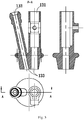
Fig. 3 is a structural diagram of the lock buckle of the present application; -
Fig. 4 is a structural diagram of the tail bed of the present application; -
Fig. 5 is a structural diagram of the three-way connector of the present application; -
Fig. 6 is a structural diagram of the four-way connector of the present application; -
Fig. 7 is a schematic diagram of the mounting of the probe tube and the probe head of the present application; and -
Fig. 8 is a structural diagram of the probe head of the present application. - The reference numbers in the drawings: 11-lock buckle, 12-tail bed, 13-three-way connector, 14-four-way connector, 15-locking screw, 16-valve, 17-probe tube, 18-probe head, 19-thick pipe, 20-thin pipe, 21-lock buckle cap; 131-first connecting end, 132-second connecting end, and 133-third connecting end.
- The preferable embodiments of the present application will be particularly described below with reference to the drawings. The drawings form a portion of the present application, and are for explaining the principle of the present application together with the embodiments of the present application.
- The present application discloses an automatic endoscope locking device. As shown in
Fig. 1 , the automatic endoscope locking device comprises: alock buckle 11, atail bed 12, a three-way connector 13, a four-way connector 14, alocking screw 15, avalve 16, aprobe tube 17, aprobe head 18, athick pipe 19, athin pipe 20 and alock buckle cap 21. - The
lock buckle 11 is mounted on thetail bed 12, thetail bed 12 is connected to a first connectingend 131 of the three-way connector 13, a second connectingend 132 of the three-way connector 13 is an instrument entrance, a third connectingend 133 of the three-way connector 13 is connected to a connecting end of the four-way connector 14, one end of theprobe tube 17 is connected to another connecting end of the four-way connector 14, and theprobe head 18 is connected to the other end of theprobe tube 17. - The locking device is of a snap ring type, and the lock buckle 11is elastically connected to the
tail bed 12 via an elastic rubber ring. - As shown in
Fig. 3 , thelock buckle 11 is of a cuboidal sheet structure. One end of thelock buckle 11 is a step having a circular arc transition, and alock buckle cap 21 is mounted on the step, for pressing the lock buckle, to facilitate the operation. The other end of thelock buckle 11 is a circular arc, and thelock buckle 11 is provided with an oblong hole in the center, which is the central hole. The circular arc end of thelock buckle 11 is provided with a protrusion, the protrusion is provided with a groove for mounting the elastic rubber ring, the protrusion is of a circular arc shape, and the circular arc shape matches with the shape of the position of thetail bed 12 where thelock buckle 11 is mounted, to facilitate thelock buckle 11 mounting on thetail bed 12. The radius of the end of the central hole adjacent to the circular arc end of thelock buckle 11 is equal to the radius of the endoscope, whereby the endoscope can be fastened without scratching the surface of the endoscope, and the radius of the other end of the central hole is greater than the radius of the endoscope, to facilitate the mounting. - As shown in
Fig. 4 , thetail bed 12 is of a funnel shape having a central hole, thetail bed 12 comprises a top portion and a neck portion, and the top portion of thetail bed 12 is provided with a slot for mounting thelock buckle 11 and a groove for mounting the elastic rubber ring. The two sides of the slot are closed, to prevent the mismatching of the central hole of thelock buckle 11 and the hole within thetail bed 12, and the two ends of the slot are open, to enable thelock buckle 11 to move reciprocatedly within the slot along the oblong hole. The top portion of the central hole of thetail bed 12 is a connector for mounting the endoscope, the connector is provided with a hole therewithin, and a diameter of the hole is greater than a diameter of the endoscope, to facilitate the mounting. - The
lock buckle 11 is mounted within the slot of thetail bed 12 via the central hole of thelock buckle 11, and is movable reciprocatedly. The elastic rubber ring is mounted in the groove of thelock buckle 11 and the groove of thetail bed 12, so that thelock buckle 11 and thetail bed 12 are elastically connected. In the normal state, because the elastic rubber ring has elasticity, the step end of thelock buckle 11 is deviated from the central hole of thetail bed 12, the end that has the equal radius with the endoscope of the central hole of thelock buckle 11 coincides with the connector of thetail bed 12, the other end of the central hole of thelock buckle 11 is blocked by the tip of thetail bed 12. When the step end of thelock buckle 11 is being pressed, the end of the central hole of thelock buckle 11 that is greater than the radius of the endoscope coincides with the connector of thetail bed 12, and the other end of the central hole of thelock buckle 11 is blocked by the tip of thetail bed 12, at which time the endoscope can be installed. - When the endoscope is being installed, the step end of the
lock buckle 11 is pressed, and the central hole on thelock buckle 11 that has the radius equal to that of the connector of thetail bed 12 coincides with the hole of the connector end of thetail bed 12, the endoscope is inserted into thelock buckle 11 and thetail bed 12, the step end of thelock buckle 11 is released, and because the elastic rubber ring has elasticity, thelock buckle 11 is repositioned, and the oblong hole of thelock buckle 11 with the radius equal to that of the endoscope clips the endoscope, and the endoscope is fixed. - In this embodiment, preferably, the radiuses of the oblong hole of the center of the
lock buckle 11 are R6.2mm and R5.3mm, the total length of the oblong hole is 16.6mm, the cross-section of the grooves on thelock buckle 11 and thetail bed 12 for mounting the elastic rubber ring are of a circular arc shape, the radius of the circular arc of the groove on thelock buckle 11 is R1mm, and the radius of the circular arc of the groove on thetail bed 12 is R1.2mm. The thickness of thelock buckle 11 is 1.2mm, and the thickness of the slot for mounting the lock buckle on thetail bed 12 is 1.4mm. - The
tail bed 12 is fixedly connected to one end of the three-way connector 13 by a key slot and thelocking screw 15. - As shown in
Fig. 4 , the neck portion of thetail bed 12 is a straight column section whose outer wall has a step, which can be very easily inserted into a through hole of the three-way connector 13. The outer wall surface of the straight column section is provided with a key-shaped protrusion, and the protrusion is provided with a rectangular slot, wherein the rectangular slot is for mounting the locking screw. As shown inFig. 5 , the three-way connector 13 is provided with three port ends, wherein the first connectingend 131 is connected to thetail bed 12. The first connectingend 131 is a straight column section whose interior has a two-section stepped hole and whose outer wall surface has a square tab. The first section of the stepped hole is an inner hole having a key slot, and the key slot is matched with the key-shaped protrusion of the tail bed. The inner diameter of the second section of the stepped hole is less than the inner diameter of the first section. The square tab is located on the outer wall corresponding to the key slot, the square tab is provided with a threaded through hole in the center, and the threaded through hole extends to the inner surface of the key slot, for mounting the locking screw. - The straight column section of the
tail bed 12 is inserted into the first section of the stepped hole of the three-way connector 13, and the key slot is in clearance fit to the key-shaped protrusion, which facilitates the dismounting. The lockingscrew 15 passes through the threaded through hole of the tab of the three-way connector 13, and is screwed into the rectangular slot of thetail bed 12 tightly, whereby thetail bed 12 is fixed on the three-way connector 13. The rectangular slot of thetail bed 12 is of an elongated shape, and the lockingscrew 15 may be fixed at any position of the rectangular slot. When the position of thetail bed 12 is required to be changed, the lockingscrew 15 is unscrewed, thetail bed 12 is moved to the required position, and the lockingscrew 15 is screwed tightly again. In this way, although the dimensions of thetail bed 12 and the three-way connector 13 are not greatly changed, the position of the lockingscrew 15 in the rectangular slot can be varied according to the demands, to in turn vary the position of thetail bed 12. Such a variation of a small amplitude can hugely facilitate the practice operations. - As shown in
Fig. 5 , the second connectingend 132 of the three-way connector 13 is inclined by 12°, for the inserting of instruments such as surgical scissors. The thirdconnecting end 133 of the three-way connector 13 directly communicates with the first connectingend 131, and the third connectingend 133 has a diameter greater than that of the second stepped section of the first connectingend 131. The thirdconnecting end 133 of the three-way connector 13 is connected to the top of the four-way connector 14, the left and right ends of the four-way connector 14 are respectively connected to a water inlet pipe and a water outlet pipe, the water in the water inlet pipe enters a human body via the left end of the four-way connector 14, the contaminated water in the human body is discharged via the right end of the four-way connector 14, and the left and right ends of the four-way connector 14 are provided with through holes for mounting thevalve 16, to control the connecting and breaking of the pipeline. The bottom end of the four-way connector 14 is connected to one end of theprobe tube 17, and the other end of theprobe tube 17 is connected to theprobe head 18. - As shown in
Fig. 6 , an oblong through hole is between the upper and lower ends of the four-way connector 14, and both of the left and right ends of the four-way connector 14 are provided with through holes, which communicate with one end of the oblong hole. - As shown in
Fig. 7 , theprobe tube 17 is a long-cylinder-shaped straight tube, with a cross-section of an oblong shape, and comprises two straight through round holes, one with a larger diameter and the other one with a smaller diameter, and the two straight through round holes do not communicate. - The
probe head 18 is a long-cylinder-shaped straight tube, and comprises two straight through round holes, one with a larger diameter and the other one with a smaller diameter. The front end of the straight through round hole with the larger diameter is inclined by 60°, and the inclining position is provided with a transparent viewing window. The round hole with the larger diameter is closed by the transparent viewing window, and the transparent viewing window facilitates the observation with the endoscope. The tip of the straight through round hole with the larger diameter is a round tip with a circular arc transition, whereby the sheath can be conveniently inserted into a human body, and not cause scratching. The length of the round hole with the smaller diameter is shorter than the length of the round hole with the larger diameter, and the tip of the straight through round hole with the smaller diameter is inclined by 60°. - The
thick pipe 19 is mounted within the round tube with the larger diameter of theprobe tube 17, and thethin pipe 20 is mounted within the round tube with the smaller diameter. One end of thethick pipe 19 is inserted into the round tube with the larger diameter of theprobe head 18 via theprobe tube 17, and is fixedly connected to the probe head, and the other end of thethick pipe 19 is inserted into the first section of the stepped hole of the first connectingend 131 of the three-way connector 13 via an oblong through hole of the four-way connector 14. The inner diameter of the second section of the stepped hole of the first connectingend 131 is less than the external diameter of thethick pipe 19, so that thethick pipe 19 and the first connectingend 131 are connection of interference fit, whereby theprobe head 18 is fixed to theprobe tube 17 via thethick pipe 19. Thethin pipe 20 is mounted within one end of the oblong hole of the four-way connector 14, and the end of the oblong hole is adjacent to the left and right through holes, thethin pipe 20 communicate with the left and right through holes, and thethick pipe 19 is mounted at the other end of the oblong hole. Thethin pipe 20 is mounted within the round hole with the smaller diameter of the probe tube, wherein one end is fixed to the oblong through hole of the four-way connector 14, and communicates with the through holes of the left and right ends of the four-way connector 14, and the other end is inserted into theprobe head 18. - One end of the
thick pipe 19 is fixed within the round hole with the larger diameter of theprobe head 18. Theprobe tube 17, the four-way connector 14 and thethick pipe 19 are in clearance fit, to enable thethick pipe 19 to be very easily drawn from the round hole. Thethick pipe 19 is in interference fit to the first connectingend 131 of the three-way connector 13, whereby thethick pipe 19 does not fall freely during usage. The outer surface of thethick pipe 19 is printed with a plurality of strip-shaped metal round rings, to increase the friction between thethick pipe 19 and the inner wall of theprobe tube 17, and to prevent thethick pipe 19 from falling in the process of drawing thethick pipe 19. - Endoscope sheaths are generally formed by extrusion integrally. The manufacturing process cannot ensure the finish degree of the inner surface of the
probe tube 17, and if the inner surface is further processed, the cost of the process is too high. Moreover, both of thethick pipe 19 and thethin pipe 20 are made from stainless steel, which can ensure the straightness and smoothness of the inner wall, and has the advantages of a high strength and a high rigidity. When thethick pipe 19 and thethin pipe 20 are mounted within the probe tube, the rigidity and strength of the probe tube can be significantly increased, and the probe tube does not easily bend and transform in the process of the insertion into a human body and does not easily fall in the process of a surgery. - On the basis of the above structures, the second connecting
end 132 of the three-way connector 13, the four-way connector 14, thethin pipe 20 within the round hole with the smaller diameter of theprobe tube 17 and theprobe head 18 form an instrument channel, for delivering the instrument into a human body in the process of a surgery for operation, and thelock buckle 11, thetail bed 12, the first connectingend 131 of the three-way connector 13 and thethick pipe 19 form an endoscope channel, for delivering the endoscope to the site to be observed. - Because the
probe head 18 is provided with the transparent viewing window at the tip, the endoscope does not contact with the human body or any liquid, which ensures the cleanness of the endoscope. By using thevalve 16 on the four-way connector 14, external water can enter the human body via the instrument channel, and then the contaminated water can be discharged via the instrument channel through thevalve 16. - In usage, firstly the sheath is inserted into the human body, a water inlet pipeline and a water outlet pipeline are respectively connected to the left and right ends of the four-
way connector 14, thevalve 16 connected to the water outlet pipeline is shut, thevalve 16 connected to the water inlet pipeline is opened, the water enters the human body via the instrument channel, then thevalve 16 connected to the water inlet pipeline is shut, thevalve 16 connected to the water outlet pipeline is opened, and the contaminated water is discharged. Thelock buckle cap 21 on thelock buckle 11 is pressed, to coincide the central hole on thelock buckle 11 that has the radius equal to that of the connector of thetail bed 12 and the hole of the connector end of thetail bed 12, the tip of the endoscope is inserted into thethick pipe 19, the transparent viewing window is used for observation, the step end of thelock buckle 11 is released, thelock buckle 11 is repositioned by the elasticity of the elastic rubber ring, and the end of the oblong hole with the radius equal to that of the endoscope clips the endoscope, and the endoscope is fixed. The instrument such as medical scissors enters the four-way connector 14 and thethin pipe 20 via the second connectingend 132 of the three-way connector 13, and passes through theprobe head 18 into the human body for operation. - After the surgery has ended, the step end of the
lock buckle 11 is pressed, to coincide the central hole on thelock buckle 11 that has the radius equal to that of the connector of thetail bed 12 and the hole of the connector end of thetail bed 12, the endoscope is taken out, the instrument is taken out at the same time, and the sheath is taken out of the human body. Because the endoscope did not contact with the human body or other liquids, the endoscope can be used for a next surgery after merely a simple disinfection, which is convenient. - In conclusion, the present application provides an automatic endoscope locking device, which fixes the endoscope by using the elasticity of the elastic rubber ring to the automatic endoscope locking device formed by the lock buckle and the tail bed. The device has a simple structure, and the assembling and detaching of the endoscope are simple, which can improve the surgery efficiency.
- The above are merely preferable particular embodiments of the present application, and the protection scope of the present application is not limited thereto. All of the variations or substitutions that a person skilled in the art can easily envisage within the technical scope disclosed by the present application should fall within the protection scope of the present application.
Claims (9)
- An automatic locking device for fixing to and locking an endoscope, comprising: a tail bed (12),
a lock buckle (11) and an elastic element;
wherein the tail bed (12) is provided with a slot for mounting the lock buckle (11), the lock buckle (11) is provided with an oblong hole in a center, and the inner wall of the lock buckle (11) forming the oblong hole is mounted within the slot of the tail bed (12) to realize the installation of the tail bed (12) and the lock buckle (11), and the lock buckle (11) is movable reciprocatedly within the slot along the oblong hole; and
the lock buckle (11) and the tail bed (12) are elastically connected by the elastic element;
the tail bed (12) is used for mounting the lock buckle (11) ;
a radius of one end of the oblong hole of the center of the lock buckle (11) is equal to a radius of the endoscope, and a radius of the other end is greater than the radius of the endoscope;
the tail bed has a central hole for receiving the endoscope, the top portion of said central hole of the tail bed is a connector for mounting the endoscope wherein the connector has a round hole provided therein with a diameter greater than the diameter of the endoscope. - The automatic locking device for locking an endoscope according to claim 1, wherein the slot of the tail bed (12) is closed at two sides and is open at two ends.
- The automatic locking device for locking an endoscope according to claim 1, wherein the elastic element is an elastic rubber ring.
- The automatic locking device for locking an endoscope according to claim 4, wherein the tail bed (12) is provided with a groove for mounting the elastic rubber ring.
- The automatic locking device for locking an endoscope according to claim 4, wherein the lock buckle (11) is of a cuboidal sheet structure, wherein one end of the lock buckle (11) is a step having a circular arc transition, the other end is a circular arc, the circular arc end is provided with a protrusion, and the protrusion is provided with a groove for mounting the elastic rubber ring.
- The automatic locking device for locking an endoscope according to claim 5, wherein the elastic rubber ring is mounted in the groove of the lock buckle (11) and the groove of the tail bed (12), and the lock buckle (11) and the tail bed (12) are elastically connected.
- The automatic locking device for locking an endoscope according to claim 6, wherein the tail bed (12) is of a funnel shape having a central hole, the tail bed (12) comprises a top portion and a neck portion, the top portion of the central hole of the tail bed (12) is a connector for mounting the endoscope, the connector is provided with a round hole.
- The automatic locking device for locking an endoscope according to claim 7, wherein a lock buckle cap (21) is mounted on the step of the lock buckle (11).
- An endoscope sheath, comprising an automatic locking device for locking an endoscope according to any one of claims 1-8, a three-way connector (13), a four-way connector (14), a locking screw (15), a valve (16), a probe tube (17), a probe head (18), a thick pipe (19), a thin pipe (20) and a lock buckle cap (21);
and the automatic endoscope locking device is connected to a first connecting end (131) of the three-way connector (13), a second connecting end (132) of the three-way connector (13) is an instrument entrance, a third connecting end (133) of the three-way connector (13) is connected to a connecting end of the four-way connector (14), one end of the probe tube (17) is connected to another connecting end of the four-way connector (14), and the probe head (18) is connected to the other end of the probe tube (17).
Applications Claiming Priority (2)
| Application Number | Priority Date | Filing Date | Title |
|---|---|---|---|
| CN201621174142.0U CN206473349U (en) | 2016-11-02 | 2016-11-02 | A kind of endoscope forced locking device |
| PCT/CN2017/087189 WO2018082301A1 (en) | 2016-11-02 | 2017-06-05 | Automatic locking mechanism for endoscope |
Publications (3)
| Publication Number | Publication Date |
|---|---|
| EP3536219A1 EP3536219A1 (en) | 2019-09-11 |
| EP3536219A4 EP3536219A4 (en) | 2020-06-03 |
| EP3536219B1 true EP3536219B1 (en) | 2021-08-04 |
Family
ID=59757199
Family Applications (1)
| Application Number | Title | Priority Date | Filing Date |
|---|---|---|---|
| EP17866603.8A Active EP3536219B1 (en) | 2016-11-02 | 2017-06-05 | Automatic locking mechanism for endoscope |
Country Status (4)
| Country | Link |
|---|---|
| US (1) | US11737655B2 (en) |
| EP (1) | EP3536219B1 (en) |
| CN (1) | CN206473349U (en) |
| WO (1) | WO2018082301A1 (en) |
Families Citing this family (2)
| Publication number | Priority date | Publication date | Assignee | Title |
|---|---|---|---|---|
| CN112807101B (en) * | 2021-02-02 | 2024-07-02 | 上海视介光电科技有限公司 | Rotary support for endoscope |
| CN114767032B (en) * | 2022-04-06 | 2024-10-25 | 瑞龙诺赋(上海)医疗科技有限公司 | Endoscope adapter |
Family Cites Families (21)
| Publication number | Priority date | Publication date | Assignee | Title |
|---|---|---|---|---|
| US5456673A (en) * | 1994-03-23 | 1995-10-10 | Stryker Corporation | Locking cannula for endoscopic surgery |
| US5792045A (en) * | 1994-10-03 | 1998-08-11 | Adair; Edwin L. | Sterile surgical coupler and drape |
| US6086530A (en) * | 1998-10-30 | 2000-07-11 | Mack; Michael | Adjustable sleeve for endoscopes |
| US6132402A (en) * | 1999-02-02 | 2000-10-17 | Bioform Inc. | Storage and delivery device for a catheter or needle |
| TW517607U (en) | 2002-03-05 | 2003-01-11 | Ming-Jen Chen | Long handled spray gun with a rotary head |
| JP2006009395A (en) * | 2004-06-25 | 2006-01-12 | Kvk Corp | Water faucet mounting structure |
| DE102004032523B4 (en) * | 2004-07-06 | 2012-02-02 | Richard Wolf Gmbh | Medical instrument |
| US8550743B2 (en) * | 2005-09-30 | 2013-10-08 | Medtronic, Inc. | Sliding lock device |
| US7511732B2 (en) * | 2006-03-30 | 2009-03-31 | Crucible Technologies, Llc | Assembly and method for securing an endoscope to a digital camera |
| CN100569175C (en) * | 2008-07-21 | 2009-12-16 | 李英奎 | Disposal vesica urinaria examination mirror sheath |
| FR2945723B1 (en) * | 2009-05-19 | 2012-06-15 | Axess Vision Technology | MEDICAL INSTRUMENT WITH MULTIPLE FUNCTIONS FOR ENDOSCOPE. |
| JP5401283B2 (en) * | 2009-11-30 | 2014-01-29 | 日本コヴィディエン株式会社 | Endoscope cover fixing tool and fixing method |
| CN101964263B (en) * | 2010-10-22 | 2012-07-25 | 施耐德万高(天津)电气设备有限公司 | Automatic change-over switch with handle locking function |
| CN102283684B (en) * | 2011-09-24 | 2013-08-14 | 天津博朗科技发展有限公司 | Disposable dual-channel endoscope sheath |
| JP2013155932A (en) * | 2012-01-30 | 2013-08-15 | Chiyoda Seisakusho Co Ltd | Pipe body attaching tool |
| US20160120395A1 (en) * | 2012-09-25 | 2016-05-05 | Tianjin Bolang Science-Technology Development Co. , Ltd. | Disposable endoscope sheath |
| CN103445748A (en) * | 2013-09-18 | 2013-12-18 | 天津博朗科技发展有限公司 | Disposable locking structure of endoscope sheath |
| WO2015076154A1 (en) * | 2013-11-21 | 2015-05-28 | オリンパスメディカルシステムズ株式会社 | Endoscopic treatment device |
| CN105816208B (en) * | 2016-05-25 | 2018-08-21 | 南京微创医学科技股份有限公司 | A kind of seal wire lock on endoscope |
| CN106618448B (en) * | 2016-11-02 | 2018-09-28 | 张立军 | A kind of fastening of endoscope and regulating device |
| CN106361388A (en) * | 2016-11-02 | 2017-02-01 | 张立军 | Endoscope sheath probe tube and manufacturing method thereof |
-
2016
- 2016-11-02 CN CN201621174142.0U patent/CN206473349U/en active Active
-
2017
- 2017-06-05 US US16/346,971 patent/US11737655B2/en active Active
- 2017-06-05 EP EP17866603.8A patent/EP3536219B1/en active Active
- 2017-06-05 WO PCT/CN2017/087189 patent/WO2018082301A1/en not_active Ceased
Also Published As
| Publication number | Publication date |
|---|---|
| US11737655B2 (en) | 2023-08-29 |
| CN206473349U (en) | 2017-09-08 |
| EP3536219A4 (en) | 2020-06-03 |
| EP3536219A1 (en) | 2019-09-11 |
| WO2018082301A1 (en) | 2018-05-11 |
| US20200060515A1 (en) | 2020-02-27 |
Similar Documents
| Publication | Publication Date | Title |
|---|---|---|
| US12082778B2 (en) | Endoscope head | |
| EP2623019B1 (en) | Arthroscope rotation mechanism | |
| JP7344266B2 (en) | Surgical introducer with guidance system receptacle | |
| US11376090B2 (en) | Endoscope, and endoscope system | |
| CN111970951B (en) | Endoscope and method for mounting elongate member | |
| ES2685644T3 (en) | Secondary endoscope attachable to a main endoscope and combination of main endoscope and secondary endoscope | |
| KR20190032610A (en) | The cannula in which the camera is installed close- | |
| CN206120288U (en) | Novel endoscope plug -in package | |
| US20190059709A1 (en) | Insert tube and endoscope using the same | |
| US9974428B2 (en) | Endoscope | |
| EP3536219A1 (en) | Automatic locking mechanism for endoscope | |
| US10307047B2 (en) | Illuminated mircorsurgical probe | |
| US11564558B2 (en) | Adjustable endoscope fixing device | |
| US20200129049A1 (en) | Sterile sheath for confocal endomicroscopy scanner probe | |
| CN106618448B (en) | A kind of fastening of endoscope and regulating device | |
| US20240008896A1 (en) | Expandable surgical access port | |
| CN110251054B (en) | Cap for use at distal end of endoscope and cap forming method | |
| KR200438922Y1 (en) | Medical device lens protective cover | |
| ATE211818T1 (en) | DEVICE FOR TESTING AND ASSESSING THE CONDITION OF ENDOSCOPES | |
| CN223095862U (en) | Mirror sheath type sterilizing box | |
| US20190336239A1 (en) | Connector For A Surgical Lighting System | |
| CN206473350U (en) | A kind of endoscope sheath inserting tube | |
| JP2013183960A (en) | Flexible endoscope with insertion shape detection function | |
| EP3435833B1 (en) | Instrument tip protector | |
| WO2022136149A1 (en) | An endoscope |
Legal Events
| Date | Code | Title | Description |
|---|---|---|---|
| STAA | Information on the status of an ep patent application or granted ep patent |
Free format text: STATUS: THE INTERNATIONAL PUBLICATION HAS BEEN MADE |
|
| PUAI | Public reference made under article 153(3) epc to a published international application that has entered the european phase |
Free format text: ORIGINAL CODE: 0009012 |
|
| STAA | Information on the status of an ep patent application or granted ep patent |
Free format text: STATUS: REQUEST FOR EXAMINATION WAS MADE |
|
| 17P | Request for examination filed |
Effective date: 20190529 |
|
| AK | Designated contracting states |
Kind code of ref document: A1 Designated state(s): AL AT BE BG CH CY CZ DE DK EE ES FI FR GB GR HR HU IE IS IT LI LT LU LV MC MK MT NL NO PL PT RO RS SE SI SK SM TR |
|
| AX | Request for extension of the european patent |
Extension state: BA ME |
|
| RAP1 | Party data changed (applicant data changed or rights of an application transferred) |
Owner name: SHENYANG SHENGSHI MEDICAL TECHNOLOGY CO., LTD. |
|
| RIN1 | Information on inventor provided before grant (corrected) |
Inventor name: ZHU, TAO Inventor name: GAO, WEI Inventor name: ZHANG, LIJUN |
|
| DAV | Request for validation of the european patent (deleted) | ||
| DAX | Request for extension of the european patent (deleted) | ||
| A4 | Supplementary search report drawn up and despatched |
Effective date: 20200504 |
|
| RIC1 | Information provided on ipc code assigned before grant |
Ipc: A61B 1/04 20060101AFI20200424BHEP Ipc: A61B 17/00 20060101ALI20200424BHEP |
|
| GRAP | Despatch of communication of intention to grant a patent |
Free format text: ORIGINAL CODE: EPIDOSNIGR1 |
|
| STAA | Information on the status of an ep patent application or granted ep patent |
Free format text: STATUS: GRANT OF PATENT IS INTENDED |
|
| INTG | Intention to grant announced |
Effective date: 20210316 |
|
| GRAS | Grant fee paid |
Free format text: ORIGINAL CODE: EPIDOSNIGR3 |
|
| GRAA | (expected) grant |
Free format text: ORIGINAL CODE: 0009210 |
|
| STAA | Information on the status of an ep patent application or granted ep patent |
Free format text: STATUS: THE PATENT HAS BEEN GRANTED |
|
| AK | Designated contracting states |
Kind code of ref document: B1 Designated state(s): AL AT BE BG CH CY CZ DE DK EE ES FI FR GB GR HR HU IE IS IT LI LT LU LV MC MK MT NL NO PL PT RO RS SE SI SK SM TR |
|
| REG | Reference to a national code |
Ref country code: GB Ref legal event code: FG4D |
|
| REG | Reference to a national code |
Ref country code: AT Ref legal event code: REF Ref document number: 1416109 Country of ref document: AT Kind code of ref document: T Effective date: 20210815 |
|
| REG | Reference to a national code |
Ref country code: CH Ref legal event code: EP |
|
| REG | Reference to a national code |
Ref country code: DE Ref legal event code: R096 Ref document number: 602017043607 Country of ref document: DE |
|
| REG | Reference to a national code |
Ref country code: IE Ref legal event code: FG4D |
|
| REG | Reference to a national code |
Ref country code: LT Ref legal event code: MG9D |
|
| REG | Reference to a national code |
Ref country code: NL Ref legal event code: MP Effective date: 20210804 |
|
| REG | Reference to a national code |
Ref country code: AT Ref legal event code: MK05 Ref document number: 1416109 Country of ref document: AT Kind code of ref document: T Effective date: 20210804 |
|
| PG25 | Lapsed in a contracting state [announced via postgrant information from national office to epo] |
Ref country code: HR Free format text: LAPSE BECAUSE OF FAILURE TO SUBMIT A TRANSLATION OF THE DESCRIPTION OR TO PAY THE FEE WITHIN THE PRESCRIBED TIME-LIMIT Effective date: 20210804 Ref country code: FI Free format text: LAPSE BECAUSE OF FAILURE TO SUBMIT A TRANSLATION OF THE DESCRIPTION OR TO PAY THE FEE WITHIN THE PRESCRIBED TIME-LIMIT Effective date: 20210804 Ref country code: ES Free format text: LAPSE BECAUSE OF FAILURE TO SUBMIT A TRANSLATION OF THE DESCRIPTION OR TO PAY THE FEE WITHIN THE PRESCRIBED TIME-LIMIT Effective date: 20210804 Ref country code: RS Free format text: LAPSE BECAUSE OF FAILURE TO SUBMIT A TRANSLATION OF THE DESCRIPTION OR TO PAY THE FEE WITHIN THE PRESCRIBED TIME-LIMIT Effective date: 20210804 Ref country code: SE Free format text: LAPSE BECAUSE OF FAILURE TO SUBMIT A TRANSLATION OF THE DESCRIPTION OR TO PAY THE FEE WITHIN THE PRESCRIBED TIME-LIMIT Effective date: 20210804 Ref country code: LT Free format text: LAPSE BECAUSE OF FAILURE TO SUBMIT A TRANSLATION OF THE DESCRIPTION OR TO PAY THE FEE WITHIN THE PRESCRIBED TIME-LIMIT Effective date: 20210804 Ref country code: AT Free format text: LAPSE BECAUSE OF FAILURE TO SUBMIT A TRANSLATION OF THE DESCRIPTION OR TO PAY THE FEE WITHIN THE PRESCRIBED TIME-LIMIT Effective date: 20210804 Ref country code: BG Free format text: LAPSE BECAUSE OF FAILURE TO SUBMIT A TRANSLATION OF THE DESCRIPTION OR TO PAY THE FEE WITHIN THE PRESCRIBED TIME-LIMIT Effective date: 20211104 Ref country code: PT Free format text: LAPSE BECAUSE OF FAILURE TO SUBMIT A TRANSLATION OF THE DESCRIPTION OR TO PAY THE FEE WITHIN THE PRESCRIBED TIME-LIMIT Effective date: 20211206 Ref country code: NO Free format text: LAPSE BECAUSE OF FAILURE TO SUBMIT A TRANSLATION OF THE DESCRIPTION OR TO PAY THE FEE WITHIN THE PRESCRIBED TIME-LIMIT Effective date: 20211104 |
|
| PG25 | Lapsed in a contracting state [announced via postgrant information from national office to epo] |
Ref country code: PL Free format text: LAPSE BECAUSE OF FAILURE TO SUBMIT A TRANSLATION OF THE DESCRIPTION OR TO PAY THE FEE WITHIN THE PRESCRIBED TIME-LIMIT Effective date: 20210804 Ref country code: LV Free format text: LAPSE BECAUSE OF FAILURE TO SUBMIT A TRANSLATION OF THE DESCRIPTION OR TO PAY THE FEE WITHIN THE PRESCRIBED TIME-LIMIT Effective date: 20210804 Ref country code: GR Free format text: LAPSE BECAUSE OF FAILURE TO SUBMIT A TRANSLATION OF THE DESCRIPTION OR TO PAY THE FEE WITHIN THE PRESCRIBED TIME-LIMIT Effective date: 20211105 |
|
| PG25 | Lapsed in a contracting state [announced via postgrant information from national office to epo] |
Ref country code: NL Free format text: LAPSE BECAUSE OF FAILURE TO SUBMIT A TRANSLATION OF THE DESCRIPTION OR TO PAY THE FEE WITHIN THE PRESCRIBED TIME-LIMIT Effective date: 20210804 |
|
| PG25 | Lapsed in a contracting state [announced via postgrant information from national office to epo] |
Ref country code: DK Free format text: LAPSE BECAUSE OF FAILURE TO SUBMIT A TRANSLATION OF THE DESCRIPTION OR TO PAY THE FEE WITHIN THE PRESCRIBED TIME-LIMIT Effective date: 20210804 |
|
| REG | Reference to a national code |
Ref country code: DE Ref legal event code: R097 Ref document number: 602017043607 Country of ref document: DE |
|
| PG25 | Lapsed in a contracting state [announced via postgrant information from national office to epo] |
Ref country code: SM Free format text: LAPSE BECAUSE OF FAILURE TO SUBMIT A TRANSLATION OF THE DESCRIPTION OR TO PAY THE FEE WITHIN THE PRESCRIBED TIME-LIMIT Effective date: 20210804 Ref country code: SK Free format text: LAPSE BECAUSE OF FAILURE TO SUBMIT A TRANSLATION OF THE DESCRIPTION OR TO PAY THE FEE WITHIN THE PRESCRIBED TIME-LIMIT Effective date: 20210804 Ref country code: RO Free format text: LAPSE BECAUSE OF FAILURE TO SUBMIT A TRANSLATION OF THE DESCRIPTION OR TO PAY THE FEE WITHIN THE PRESCRIBED TIME-LIMIT Effective date: 20210804 Ref country code: EE Free format text: LAPSE BECAUSE OF FAILURE TO SUBMIT A TRANSLATION OF THE DESCRIPTION OR TO PAY THE FEE WITHIN THE PRESCRIBED TIME-LIMIT Effective date: 20210804 Ref country code: CZ Free format text: LAPSE BECAUSE OF FAILURE TO SUBMIT A TRANSLATION OF THE DESCRIPTION OR TO PAY THE FEE WITHIN THE PRESCRIBED TIME-LIMIT Effective date: 20210804 Ref country code: AL Free format text: LAPSE BECAUSE OF FAILURE TO SUBMIT A TRANSLATION OF THE DESCRIPTION OR TO PAY THE FEE WITHIN THE PRESCRIBED TIME-LIMIT Effective date: 20210804 |
|
| PLBE | No opposition filed within time limit |
Free format text: ORIGINAL CODE: 0009261 |
|
| STAA | Information on the status of an ep patent application or granted ep patent |
Free format text: STATUS: NO OPPOSITION FILED WITHIN TIME LIMIT |
|
| 26N | No opposition filed |
Effective date: 20220506 |
|
| PG25 | Lapsed in a contracting state [announced via postgrant information from national office to epo] |
Ref country code: IT Free format text: LAPSE BECAUSE OF FAILURE TO SUBMIT A TRANSLATION OF THE DESCRIPTION OR TO PAY THE FEE WITHIN THE PRESCRIBED TIME-LIMIT Effective date: 20210804 |
|
| PG25 | Lapsed in a contracting state [announced via postgrant information from national office to epo] |
Ref country code: SI Free format text: LAPSE BECAUSE OF FAILURE TO SUBMIT A TRANSLATION OF THE DESCRIPTION OR TO PAY THE FEE WITHIN THE PRESCRIBED TIME-LIMIT Effective date: 20210804 |
|
| PG25 | Lapsed in a contracting state [announced via postgrant information from national office to epo] |
Ref country code: MC Free format text: LAPSE BECAUSE OF FAILURE TO SUBMIT A TRANSLATION OF THE DESCRIPTION OR TO PAY THE FEE WITHIN THE PRESCRIBED TIME-LIMIT Effective date: 20210804 |
|
| REG | Reference to a national code |
Ref country code: CH Ref legal event code: PL |
|
| REG | Reference to a national code |
Ref country code: BE Ref legal event code: MM Effective date: 20220630 |
|
| GBPC | Gb: european patent ceased through non-payment of renewal fee |
Effective date: 20220605 |
|
| PG25 | Lapsed in a contracting state [announced via postgrant information from national office to epo] |
Ref country code: LU Free format text: LAPSE BECAUSE OF NON-PAYMENT OF DUE FEES Effective date: 20220605 Ref country code: LI Free format text: LAPSE BECAUSE OF NON-PAYMENT OF DUE FEES Effective date: 20220630 Ref country code: IE Free format text: LAPSE BECAUSE OF NON-PAYMENT OF DUE FEES Effective date: 20220605 Ref country code: FR Free format text: LAPSE BECAUSE OF NON-PAYMENT OF DUE FEES Effective date: 20220630 Ref country code: CH Free format text: LAPSE BECAUSE OF NON-PAYMENT OF DUE FEES Effective date: 20220630 |
|
| PG25 | Lapsed in a contracting state [announced via postgrant information from national office to epo] |
Ref country code: GB Free format text: LAPSE BECAUSE OF NON-PAYMENT OF DUE FEES Effective date: 20220605 Ref country code: BE Free format text: LAPSE BECAUSE OF NON-PAYMENT OF DUE FEES Effective date: 20220630 |
|
| PG25 | Lapsed in a contracting state [announced via postgrant information from national office to epo] |
Ref country code: HU Free format text: LAPSE BECAUSE OF FAILURE TO SUBMIT A TRANSLATION OF THE DESCRIPTION OR TO PAY THE FEE WITHIN THE PRESCRIBED TIME-LIMIT; INVALID AB INITIO Effective date: 20170605 |
|
| PG25 | Lapsed in a contracting state [announced via postgrant information from national office to epo] |
Ref country code: MK Free format text: LAPSE BECAUSE OF FAILURE TO SUBMIT A TRANSLATION OF THE DESCRIPTION OR TO PAY THE FEE WITHIN THE PRESCRIBED TIME-LIMIT Effective date: 20210804 Ref country code: CY Free format text: LAPSE BECAUSE OF FAILURE TO SUBMIT A TRANSLATION OF THE DESCRIPTION OR TO PAY THE FEE WITHIN THE PRESCRIBED TIME-LIMIT Effective date: 20210804 |
|
| PG25 | Lapsed in a contracting state [announced via postgrant information from national office to epo] |
Ref country code: TR Free format text: LAPSE BECAUSE OF FAILURE TO SUBMIT A TRANSLATION OF THE DESCRIPTION OR TO PAY THE FEE WITHIN THE PRESCRIBED TIME-LIMIT Effective date: 20210804 |
|
| PG25 | Lapsed in a contracting state [announced via postgrant information from national office to epo] |
Ref country code: MT Free format text: LAPSE BECAUSE OF FAILURE TO SUBMIT A TRANSLATION OF THE DESCRIPTION OR TO PAY THE FEE WITHIN THE PRESCRIBED TIME-LIMIT Effective date: 20210804 |
|
| PGFP | Annual fee paid to national office [announced via postgrant information from national office to epo] |
Ref country code: DE Payment date: 20250618 Year of fee payment: 9 |