EP3536144B1 - Lawnmower with ultrasound deterrent device for wild animals - Google Patents
Lawnmower with ultrasound deterrent device for wild animals Download PDFInfo
- Publication number
- EP3536144B1 EP3536144B1 EP19161291.0A EP19161291A EP3536144B1 EP 3536144 B1 EP3536144 B1 EP 3536144B1 EP 19161291 A EP19161291 A EP 19161291A EP 3536144 B1 EP3536144 B1 EP 3536144B1
- Authority
- EP
- European Patent Office
- Prior art keywords
- angle
- angular speed
- lawnmower
- given
- ultrasound
- Prior art date
- Legal status (The legal status is an assumption and is not a legal conclusion. Google has not performed a legal analysis and makes no representation as to the accuracy of the status listed.)
- Active
Links
Images

Classifications
-
- A—HUMAN NECESSITIES
- A01—AGRICULTURE; FORESTRY; ANIMAL HUSBANDRY; HUNTING; TRAPPING; FISHING
- A01D—HARVESTING; MOWING
- A01D75/00—Accessories for harvesters or mowers
- A01D75/20—Devices for protecting men or animals
- A01D75/206—Devices for protecting men or animals for mowers carried by operator
-
- A—HUMAN NECESSITIES
- A01—AGRICULTURE; FORESTRY; ANIMAL HUSBANDRY; HUNTING; TRAPPING; FISHING
- A01D—HARVESTING; MOWING
- A01D34/00—Mowers; Mowing apparatus of harvesters
- A01D34/006—Control or measuring arrangements
- A01D34/008—Control or measuring arrangements for automated or remotely controlled operation
Definitions
- the present invention relates to a lawnmower with ultrasound deterrent device for wild animals, in particular a robotic lawnmower.
- One of said drawbacks relates to the protection of wild animals in gardens, which may come into contact with robotic lawnmowers, for example, hedgehogs.
- Ultrasound devices for keeping back wild animals such as the device described in patent DE 102008054322 B4 are known in the background art.
- the device is equipped with a body in which a piezoelectric transducer for generating ultrasounds is located, which may be activated by an electric control element with signals in the ultrasonic frequency range.
- the upper wall of the body is structured as a membrane capable of vibrating and is connected to the piezoelectric transducer by means of a junction element, and it may be moved thereby in ultrasonic oscillating movements.
- WO 2013/125992 discloses a robotic lawnmower provided with a collision sensor adapted to detect the collision of the lawnmower against an obstacle.
- the control unit of the lawnmower receives the data from the collision sensor and respond by stopping the robotic lawnmower or by changing the direction of the robotic lawnmower or by sending an alarm.
- said object is achieved by means of a lawnmower as defined in claim 1.
- the ultrasound deterrent device is not always activated but only under certain circumstance, that is only when the trajectory of the lawnmower is deviated with respect to the predefined trajectory and only if this deviation, which is angularly measured, is greater than a given angle; in this way the energy consumption of the lawnmower is minimized.
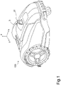
- FIGS 1-4 show a lawnmower 100, in particular a robotic lawnmower, equipped with an ultrasound deterrent device 3 for wild animals in accordance with present invention.
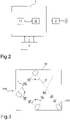
- the lawnmower 100 comprises a control unit 1 of the ultrasound deterrent device 3, as better shown in Figure 2 ; the control unit 1 may be a unit dedicated to the control of the ultrasound deterrent device 3 or it may be part of the unit for controlling the entire lawnmower.
- the ultrasound deterrent device 3 preferably comprises a piezoelectric transducer for generating ultrasounds, preferably in a frequency range from 25khz to 45khz, which may be activated by the control unit 1.
- the device 3 comprises a membrane capable of vibrating and connected to the piezoelectric transducer; the membrane performs ultrasonic oscillating movements.
- a loudspeaker 31 is provided, with a sound emission beam angle preferably of between 10° and 20°.
- the lawnmower 100 also comprises detecting means 2, for example a gyroscope, adapted to detect an angular deviation with respect to the trajectory or path L of the lawnmower which are due to the collision against an obstacle or are set by the control unit 1, particularly said detecting means are configured to detect data on said angular deviation with respect to the trajectory or path L of the lawnmower;
- the trajectory L is the trajectory which is set by the control unit 1, that is a prefixed path or direction which has been previously set for the lawnmower 100.
- the control unit 1 is configured to process the angle ⁇ of the angular deviation of the trajectory L of the lawnmower from the data received from the detecting means 2 and is configured to activate the device 3 if said angle ⁇ is greater than a given angle ⁇ 0 ; the device 3 is preferably activated for a given time period, for example for 1 second If the lawnmower collides with obstacles (such as stones or walls or a perimeter wire 50 or else) in the path or trajectory L thereof, the control unit of the entire lawnmower controls that the path or trajectory of the lawnmower must change or deviate from the previously set path or trajectory L so as to take a new trajectory; if this deviation from the previously set path or trajectory or direction L, which is angularly measured by means of the angle ⁇ , that is if the angle ⁇ between the new trajectory and the preceding trajectory of the lawnmower results greater than the given angle ⁇ 0 , the control unit 1 activates the ultrasound deterrent device 3.
- obstacles such as stones or walls or a perimeter wire
- the detecting means 2 send to the control unit 1 the angular speed components ⁇ x, ⁇ y, ⁇ z, i.e., i.e. the components of the rotation speed of the lawnmower on the three Cartesian axis X, Y and Z.
- the lawnmower rotates of the angle ⁇ by changing from the preceding trajectory to the new trajectory, i.e. the components of the angular speed vector cot of the lawnmower on the three Cartesian axis X, Y and Z.
- the control unit 1 is configured to activate the ultrasound deterrent device 3 if the trajectory L of the lawnmower detected by the detecting means 2 is deviated by an angle ⁇ greater than a given angle ⁇ 0 , preferably an angle of between 15° and 45°, still preferably an angle of 30°, as better shown in Figure 3 .
- the angular deviation of the lawnmower 100 from the trajectory L thereof may be due to the presence of obstacles in the path thereof, such as stones or walls or a perimeter wire 50 or else.
- the control unit 1 comprises processing means 11 and a memory 12 in which an operating software is installed and running, as better shown in Figure 2 .
- the software is based on an algorithm which is updated at equal time intervals ⁇ t, for example, with a duration of 20 ms. Therefore, the control unit 1 receives, during each time period ⁇ t, the data from the detecting means 2, i.e., the angular speed components ⁇ x, ⁇ y, ⁇ z, and processes them.
- the software comprises the following operational functions or steps, shown in Figure 4 .
- step A it controls the acquisition of the angular speed components ⁇ x, ⁇ y, ⁇ z.
- the software controls the calculation of the average of the values of the angular speed components ⁇ x, ⁇ y, ⁇ z contained in the n positions of the circular queue, thus obtaining an average angular speed value ⁇ .
- step D the software verifies if the average angular speed ⁇ calculated during step C is greater or lower than a given angular speed ⁇ 0 of, for example, 3°/s.
- Step F2 is followed by the next step F3, in which the software verifies if the value of the measured rotation angle ⁇ k calculated during step F2 is greater or lower than the given value ⁇ 0 , preferably an angle of between 15° and 45°, still preferably an angle of 30°.
- step F4 occurs and the control unit 1 makes the ultrasound deterrent device 3 emit the ultrasounds with a time delay Tdelay preferably of 1 s and the value of the measured rotation angle ⁇ k is set equal to zero. If, during the time delay Tdelay, the value of the measured rotation angle ⁇ k is greater than ⁇ 0 , the time delay Tdelay will be increased, for example, by 1 s.
- step F1 follows.
- step D If the average angular speed ⁇ is lower than ⁇ 0 during step D (indicated with NO in the diagram of Figure 4 ), the value of the measured rotation angle ⁇ k is not updated and step G1 occurs in which it is verified whether, for a given period T, for example, of 2 s, the average angular speed ⁇ is always kept lower than ⁇ 0 or not.
- step G2 occurs, in which the value of the measured rotation angle ⁇ k is set equal to zero. If, instead, the average angular speed ⁇ becomes greater than ⁇ 0 (indicated with NO in the diagram of Figure 4 ), step F1 follows.
Landscapes
- Life Sciences & Earth Sciences (AREA)
- Environmental Sciences (AREA)
- Catching Or Destruction (AREA)
- Harvester Elements (AREA)
- Guiding Agricultural Machines (AREA)
Description
- The present invention relates to a lawnmower with ultrasound deterrent device for wild animals, in particular a robotic lawnmower.
- Robotic lawnmowers are increasingly being used by users in recent years; said lawnmowers bring different benefits to users but also some drawbacks.
- One of said drawbacks relates to the protection of wild animals in gardens, which may come into contact with robotic lawnmowers, for example, hedgehogs.
- Ultrasound devices for keeping back wild animals, such as the device described in patent
DE 102008054322 B4 are known in the background art. The device is equipped with a body in which a piezoelectric transducer for generating ultrasounds is located, which may be activated by an electric control element with signals in the ultrasonic frequency range. The upper wall of the body is structured as a membrane capable of vibrating and is connected to the piezoelectric transducer by means of a junction element, and it may be moved thereby in ultrasonic oscillating movements. -
WO 2013/125992 discloses a robotic lawnmower provided with a collision sensor adapted to detect the collision of the lawnmower against an obstacle. The control unit of the lawnmower receives the data from the collision sensor and respond by stopping the robotic lawnmower or by changing the direction of the robotic lawnmower or by sending an alarm. - In view of the background art, it is the object of the present invention to provide a lawnmower equipped with an ultrasound deterrent device for wild animals which is activated only under certain circumstances so as to minimize energy consumption.
- In accordance with the present invention, said object is achieved by means of a lawnmower as defined in
claim 1. - By virtue of the present invention it is possible to provide a lawnmower equipped with an ultrasound deterrent device for wild animals which allows to keep back wild animals from the garden in which the lawnmower is used only when necessary, minimizing energy consumption. In fact the ultrasound deterrent device is not always activated but only under certain circumstance, that is only when the trajectory of the lawnmower is deviated with respect to the predefined trajectory and only if this deviation, which is angularly measured, is greater than a given angle; in this way the energy consumption of the lawnmower is minimized.
- The features and advantages of the present invention will become apparent from the following detailed description of an embodiment thereof, illustrated by way of non-limiting example in the accompanying drawings, in which:
-
Figure 1 shows a diagrammatic view of a lawnmower with ultrasound deterrent device for wild animals in accordance with the present invention; -
Figure 2 shows a block diagram of the control unit of the ultrasound device; -
Figure 3 shows a diagrammatic view of a possible path of the lawnmower ofFigure 1 ; -
Figure 4 shows a block diagram of the operation of the control unit ofFigure 2 . -
Figures 1-4 show alawnmower 100, in particular a robotic lawnmower, equipped with anultrasound deterrent device 3 for wild animals in accordance with present invention. - The
lawnmower 100 comprises acontrol unit 1 of theultrasound deterrent device 3, as better shown inFigure 2 ; thecontrol unit 1 may be a unit dedicated to the control of theultrasound deterrent device 3 or it may be part of the unit for controlling the entire lawnmower. - The
ultrasound deterrent device 3 preferably comprises a piezoelectric transducer for generating ultrasounds, preferably in a frequency range from 25khz to 45khz, which may be activated by thecontrol unit 1. Thedevice 3 comprises a membrane capable of vibrating and connected to the piezoelectric transducer; the membrane performs ultrasonic oscillating movements. Aloudspeaker 31 is provided, with a sound emission beam angle preferably of between 10° and 20°. - The
lawnmower 100 also comprises detecting means 2, for example a gyroscope, adapted to detect an angular deviation with respect to the trajectory or path L of the lawnmower which are due to the collision against an obstacle or are set by thecontrol unit 1, particularly said detecting means are configured to detect data on said angular deviation with respect to the trajectory or path L of the lawnmower; the trajectory L is the trajectory which is set by thecontrol unit 1, that is a prefixed path or direction which has been previously set for thelawnmower 100. Thecontrol unit 1 is configured to process the angle α of the angular deviation of the trajectory L of the lawnmower from the data received from thedetecting means 2 and is configured to activate thedevice 3 if said angle α is greater than a given angle α0; thedevice 3 is preferably activated for a given time period, for example for 1 second If the lawnmower collides with obstacles (such as stones or walls or aperimeter wire 50 or else) in the path or trajectory L thereof, the control unit of the entire lawnmower controls that the path or trajectory of the lawnmower must change or deviate from the previously set path or trajectory L so as to take a new trajectory; if this deviation from the previously set path or trajectory or direction L, which is angularly measured by means of the angle α, that is if the angle α between the new trajectory and the preceding trajectory of the lawnmower results greater than the given angle α0, thecontrol unit 1 activates theultrasound deterrent device 3. - In particular, the detecting means 2, for example a gyroscope, send to the
control unit 1 the angular speed components ωx, ωy, ωz, i.e., i.e. the components of the rotation speed of the lawnmower on the three Cartesian axis X, Y and Z. when the lawnmower rotates of the angle α by changing from the preceding trajectory to the new trajectory, i.e. the components of the angular speed vector cot of the lawnmower on the three Cartesian axis X, Y and Z. - The
control unit 1 is configured to activate theultrasound deterrent device 3 if the trajectory L of the lawnmower detected by thedetecting means 2 is deviated by an angle α greater than a given angle α0, preferably an angle of between 15° and 45°, still preferably an angle of 30°, as better shown inFigure 3 . In particular, thecontrol unit 1 obtains the angle α as a function of the angular speed components ωx, ωy, coz received from the detectingmeans 2 and verifies if said angle α is greater than a predetermined angle α0 which is preferably of between 15° and 45°, still preferably α0=30°. The angular deviation of thelawnmower 100 from the trajectory L thereof may be due to the presence of obstacles in the path thereof, such as stones or walls or aperimeter wire 50 or else. - The
control unit 1 comprises processing means 11 and amemory 12 in which an operating software is installed and running, as better shown inFigure 2 . - The software is based on an algorithm which is updated at equal time intervals Δt, for example, with a duration of 20 ms. Therefore, the
control unit 1 receives, during each time period Δt, the data from the detecting means 2, i.e., the angular speed components ωx, ωy, ωz, and processes them. - The software comprises the following operational functions or steps, shown in
Figure 4 . - During step A, it controls the acquisition of the angular speed components ωx, ωy, ωz.
- During the next step B, the three angular speed components ωx, ωy, ωz acquired are stored on a buffer, preferably a circular queue with n positions, preferably with n=20, so that the new angular speed components ωx, ωy, ωz occupy in the queue the position of the older angular speed components ωx, ωy, ωz.
- In the next step C, the software controls the calculation of the average of the values of the angular speed components ωx, ωy, ωz contained in the n positions of the circular queue, thus obtaining an average angular speed value ω.
- In the next step D, the software verifies if the average angular speed ω calculated during step C is greater or lower than a given angular speed ω0 of, for example, 3°/s.
- If the average angular speed ω is greater than ω0 (indicated with YES in the diagram of
Figure 4 ), step F1 occurs, in which the software calculates the angular variation Δα given by the average angular speed ω for the time period Δt, i.e., Δα= ω×Δt. - Step F1 is followed by the next step F2, in which the value of the measured rotation angle αk is updated, becoming equal to the sum of the previously measured angle αk-1 and the angular variation Δα, i.e., αk= αk-1+Δα.
- Step F2 is followed by the next step F3, in which the software verifies if the value of the measured rotation angle αk calculated during step F2 is greater or lower than the given value α0, preferably an angle of between 15° and 45°, still preferably an angle of 30°.
- If the value of the measured rotation angle αk is greater than α0 (indicated with YES in the diagram of
Figure 4 ), step F4 occurs and thecontrol unit 1 makes theultrasound deterrent device 3 emit the ultrasounds with a time delay Tdelay preferably of 1 s and the value of the measured rotation angle αk is set equal to zero. If, during the time delay Tdelay, the value of the measured rotation angle αk is greater than α0, the time delay Tdelay will be increased, for example, by 1 s. - If during step F3 the value of the measured rotation angle αk is lower than α0 (indicated with NO in the diagram of
Figure 4 ), step F1 follows. - If the average angular speed ω is lower than ω0 during step D (indicated with NO in the diagram of
Figure 4 ), the value of the measured rotation angle αk is not updated and step G1 occurs in which it is verified whether, for a given period T, for example, of 2 s, the average angular speed ω is always kept lower than ω0 or not. - If the average angular speed ω is always kept lower than ω0 (indicated with YES in the diagram of
Figure 4 ), step G2 occurs, in which the value of the measured rotation angle αk is set equal to zero. If, instead, the average angular speed ω becomes greater than ω0 (indicated with NO in the diagram ofFigure 4 ), step F1 follows.
Claims (8)
- A lawnmower (100) comprising an ultrasound deterrent device (3) for wild animals, means for controlling (1) said ultrasound deterrent device and detecting means (2) adapted to detect an angular deviation of the lawnmower with respect to the trajectory thereof, characterized in that said controlling means are configured to process the angle (α) of the angular deviation from the trajectory (L) of the lawnmower from the data received from said detecting means and are configured to activate said ultrasound deterrent device if said angle (α) is greater than a given angle (α0) ranging from 15° to 45° .
- A lawnmower according to claim 1, characterized in that said given angle (α0) is equal to 30°.
- A lawnmower according to any one of the preceding claims, characterized in that said controlling means (1) comprise processing means (11) and a memory (12) in which an operating software is installed, said controlling means being configured to receive (A) the angular speed components (ωx, ωy, ωz) detected by the detecting means, process (B-F) said angular speed components (ωx, ωy, ωz) to obtain said angle, verify (F1-F3) if said angle is greater than said given angle, activate said ultrasound device if said angle is greater than said given angle.
- A lawnmower according to claim 3, characterized in that said controlling means are configured to perform in sequence, for each given time period (Δt), the functions of receiving the angular speed components (ωx, ωy, ωz) detected by the detecting means, of processing said angular speed components (ωx, ωy, ωz) to obtain said angle and of verifying (F1-F3) if said angle is greater than said given angle.
- A lawnmower according to claim 4, characterized in that said controller is further configured to perform the following functions:- acquiring (A) the angular speed components (ωx, ωy, ωz) detected by the detecting means;- storing (B) the angular speed components (ωx, ωy, ωz) detected by the detecting means on an n-position buffer, so that the new angular speed components (ωx, ωy, ωz) occupy in the buffer the position of the older angular speed components (ωx, ωy, ωz);- calculating (C) the average of the values of the angular speed components (ωx, ωy, ωz) contained in the n positions of the buffer, thus obtaining an average angular speed value (ω);- verifying (D) if the average angular speed (ω), previously obtained, is greater than a given angular speed (ω0);- if the verifying function (D) gives a positive outcome, calculating (F1) the angular variation (Δα) given by the average angular speed multiplied by said time period (Δα=ω×Δt);- updating (F2) the value of the angle (αk) which becomes equal to the sum of the previously measured angle (αk-1) and the angular variation (Δα);- further verifying (F3) if the updated value of the angle (αk) is greater than said given angle (α0);- if the further verifying function (F3) gives a positive outcome, activating the ultrasound deterrent device (3) and resetting the value of the angle to zero.
- A lawnmower according to claim 5, characterized in that said function of activating the ultrasound deterrent device (3) occurs with a given time delay (Tdelay).
- A lawnmower according to claim 6, characterized in that, if the value of said given time delay (Tdelay) is greater than said time period, said controller being configured to perform the function of increasing said time delay if during said already set time delay (Tdelay) the value of the angle is greater than said given angle.
- A lawnmower according to claim 5, characterized in that, if the verifying function (D) gives a negative outcome, said controller is configured to perform the function of resetting the value of the angle to zero, if the average angular speed (ω) is always kept lower than said given angular speed (ω0) for a further time period (T).
Applications Claiming Priority (1)
| Application Number | Priority Date | Filing Date | Title |
|---|---|---|---|
| IT102018000003378A IT201800003378A1 (en) | 2018-03-08 | 2018-03-08 | Mower with ultrasonic deterrent device for wild animals. |
Publications (2)
| Publication Number | Publication Date |
|---|---|
| EP3536144A1 EP3536144A1 (en) | 2019-09-11 |
| EP3536144B1 true EP3536144B1 (en) | 2022-10-26 |
Family
ID=62386813
Family Applications (1)
| Application Number | Title | Priority Date | Filing Date |
|---|---|---|---|
| EP19161291.0A Active EP3536144B1 (en) | 2018-03-08 | 2019-03-07 | Lawnmower with ultrasound deterrent device for wild animals |
Country Status (2)
| Country | Link |
|---|---|
| EP (1) | EP3536144B1 (en) |
| IT (1) | IT201800003378A1 (en) |
Families Citing this family (1)
| Publication number | Priority date | Publication date | Assignee | Title |
|---|---|---|---|---|
| CN116490064A (en) * | 2020-12-01 | 2023-07-25 | 苏州宝时得电动工具有限公司 | Mobile robot intelligent obstacle avoidance method and mobile robot |
Family Cites Families (4)
| Publication number | Priority date | Publication date | Assignee | Title |
|---|---|---|---|---|
| SE504105C2 (en) * | 1993-10-19 | 1996-11-11 | Lars Svensson | Warning equipment for mobile device |
| GB2334874B (en) * | 1994-11-25 | 1999-11-17 | Black & Decker Inc | Lawn mower |
| EP2816885A4 (en) * | 2012-02-22 | 2015-10-14 | Husqvarna Ab | Robotic lawn mower with joystick sensor |
| WO2015115954A1 (en) * | 2014-02-03 | 2015-08-06 | Husqvarna Ab | Obstacle detection for a robotic working tool |
-
2018
- 2018-03-08 IT IT102018000003378A patent/IT201800003378A1/en unknown
-
2019
- 2019-03-07 EP EP19161291.0A patent/EP3536144B1/en active Active
Also Published As
| Publication number | Publication date |
|---|---|
| EP3536144A1 (en) | 2019-09-11 |
| IT201800003378A1 (en) | 2019-09-08 |
Similar Documents
| Publication | Publication Date | Title |
|---|---|---|
| US10571928B2 (en) | Moving robot and control method thereof | |
| EP1717660B1 (en) | Position calculation system for mobile robot and charging-stand return system and method using the same | |
| JP4991112B2 (en) | Mobile robot calling device and method thereof | |
| JP6030727B2 (en) | Coverage robot navigation | |
| CN107533134B (en) | Camera, audio sound system, method and system for detecting the position of an object | |
| KR101856503B1 (en) | Moving robot and controlling method thereof | |
| US8842495B2 (en) | Ultrasonic motion detection | |
| US20080243388A1 (en) | Autonomous driving apparatus and executing program thereof | |
| JP6831274B2 (en) | Flight equipment | |
| JP2020030825A (en) | Floor processor autonomously moving in environment | |
| EP0271523A1 (en) | Obstacle avoidance system | |
| US20040210346A1 (en) | Method and apparatus for allowing mobile robot to return to docking station | |
| US20130286783A1 (en) | Target detection and tracking with multiple ultrasonic transducers | |
| US20140297066A1 (en) | Remote control system | |
| EP3536144A1 (en) | Lawnmower with ultrasound deterrent device for wild animals | |
| US20050166357A1 (en) | Self-propelling cleaner | |
| JP2012038078A (en) | Monitoring sensor | |
| JPH04259879A (en) | Stereophonic acoustic field alarm apparatus | |
| JP2016218504A (en) | Moving device and moving system | |
| CN114340975A (en) | Information presentation device, information presentation method, and information presentation program | |
| JP2996705B2 (en) | Steering control device for automatic traveling work vehicle | |
| JP4311355B2 (en) | Self-propelled device and its program | |
| JPH043209A (en) | Steering controller for free-running car | |
| KR102545562B1 (en) | Smart finishing machine | |
| JP2017226064A (en) | Obstacle determination device |
Legal Events
| Date | Code | Title | Description |
|---|---|---|---|
| PUAI | Public reference made under article 153(3) epc to a published international application that has entered the european phase |
Free format text: ORIGINAL CODE: 0009012 |
|
| STAA | Information on the status of an ep patent application or granted ep patent |
Free format text: STATUS: THE APPLICATION HAS BEEN PUBLISHED |
|
| AK | Designated contracting states |
Kind code of ref document: A1 Designated state(s): AL AT BE BG CH CY CZ DE DK EE ES FI FR GB GR HR HU IE IS IT LI LT LU LV MC MK MT NL NO PL PT RO RS SE SI SK SM TR |
|
| AX | Request for extension of the european patent |
Extension state: BA ME |
|
| STAA | Information on the status of an ep patent application or granted ep patent |
Free format text: STATUS: REQUEST FOR EXAMINATION WAS MADE |
|
| 17P | Request for examination filed |
Effective date: 20200224 |
|
| RBV | Designated contracting states (corrected) |
Designated state(s): AL AT BE BG CH CY CZ DE DK EE ES FI FR GB GR HR HU IE IS IT LI LT LU LV MC MK MT NL NO PL PT RO RS SE SI SK SM TR |
|
| STAA | Information on the status of an ep patent application or granted ep patent |
Free format text: STATUS: EXAMINATION IS IN PROGRESS |
|
| 17Q | First examination report despatched |
Effective date: 20200708 |
|
| GRAP | Despatch of communication of intention to grant a patent |
Free format text: ORIGINAL CODE: EPIDOSNIGR1 |
|
| STAA | Information on the status of an ep patent application or granted ep patent |
Free format text: STATUS: GRANT OF PATENT IS INTENDED |
|
| INTG | Intention to grant announced |
Effective date: 20220527 |
|
| GRAS | Grant fee paid |
Free format text: ORIGINAL CODE: EPIDOSNIGR3 |
|
| GRAA | (expected) grant |
Free format text: ORIGINAL CODE: 0009210 |
|
| STAA | Information on the status of an ep patent application or granted ep patent |
Free format text: STATUS: THE PATENT HAS BEEN GRANTED |
|
| AK | Designated contracting states |
Kind code of ref document: B1 Designated state(s): AL AT BE BG CH CY CZ DE DK EE ES FI FR GB GR HR HU IE IS IT LI LT LU LV MC MK MT NL NO PL PT RO RS SE SI SK SM TR |
|
| REG | Reference to a national code |
Ref country code: GB Ref legal event code: FG4D |
|
| REG | Reference to a national code |
Ref country code: CH Ref legal event code: EP |
|
| REG | Reference to a national code |
Ref country code: AT Ref legal event code: REF Ref document number: 1526389 Country of ref document: AT Kind code of ref document: T Effective date: 20221115 |
|
| REG | Reference to a national code |
Ref country code: DE Ref legal event code: R096 Ref document number: 602019020959 Country of ref document: DE |
|
| REG | Reference to a national code |
Ref country code: IE Ref legal event code: FG4D |
|
| REG | Reference to a national code |
Ref country code: SE Ref legal event code: TRGR |
|
| REG | Reference to a national code |
Ref country code: LT Ref legal event code: MG9D |
|
| REG | Reference to a national code |
Ref country code: NL Ref legal event code: MP Effective date: 20221026 |
|
| REG | Reference to a national code |
Ref country code: AT Ref legal event code: MK05 Ref document number: 1526389 Country of ref document: AT Kind code of ref document: T Effective date: 20221026 |
|
| PG25 | Lapsed in a contracting state [announced via postgrant information from national office to epo] |
Ref country code: NL Free format text: LAPSE BECAUSE OF FAILURE TO SUBMIT A TRANSLATION OF THE DESCRIPTION OR TO PAY THE FEE WITHIN THE PRESCRIBED TIME-LIMIT Effective date: 20221026 |
|
| PG25 | Lapsed in a contracting state [announced via postgrant information from national office to epo] |
Ref country code: PT Free format text: LAPSE BECAUSE OF FAILURE TO SUBMIT A TRANSLATION OF THE DESCRIPTION OR TO PAY THE FEE WITHIN THE PRESCRIBED TIME-LIMIT Effective date: 20230227 Ref country code: NO Free format text: LAPSE BECAUSE OF FAILURE TO SUBMIT A TRANSLATION OF THE DESCRIPTION OR TO PAY THE FEE WITHIN THE PRESCRIBED TIME-LIMIT Effective date: 20230126 Ref country code: LT Free format text: LAPSE BECAUSE OF FAILURE TO SUBMIT A TRANSLATION OF THE DESCRIPTION OR TO PAY THE FEE WITHIN THE PRESCRIBED TIME-LIMIT Effective date: 20221026 Ref country code: FI Free format text: LAPSE BECAUSE OF FAILURE TO SUBMIT A TRANSLATION OF THE DESCRIPTION OR TO PAY THE FEE WITHIN THE PRESCRIBED TIME-LIMIT Effective date: 20221026 Ref country code: ES Free format text: LAPSE BECAUSE OF FAILURE TO SUBMIT A TRANSLATION OF THE DESCRIPTION OR TO PAY THE FEE WITHIN THE PRESCRIBED TIME-LIMIT Effective date: 20221026 Ref country code: AT Free format text: LAPSE BECAUSE OF FAILURE TO SUBMIT A TRANSLATION OF THE DESCRIPTION OR TO PAY THE FEE WITHIN THE PRESCRIBED TIME-LIMIT Effective date: 20221026 |
|
| PG25 | Lapsed in a contracting state [announced via postgrant information from national office to epo] |
Ref country code: RS Free format text: LAPSE BECAUSE OF FAILURE TO SUBMIT A TRANSLATION OF THE DESCRIPTION OR TO PAY THE FEE WITHIN THE PRESCRIBED TIME-LIMIT Effective date: 20221026 Ref country code: PL Free format text: LAPSE BECAUSE OF FAILURE TO SUBMIT A TRANSLATION OF THE DESCRIPTION OR TO PAY THE FEE WITHIN THE PRESCRIBED TIME-LIMIT Effective date: 20221026 Ref country code: LV Free format text: LAPSE BECAUSE OF FAILURE TO SUBMIT A TRANSLATION OF THE DESCRIPTION OR TO PAY THE FEE WITHIN THE PRESCRIBED TIME-LIMIT Effective date: 20221026 Ref country code: IS Free format text: LAPSE BECAUSE OF FAILURE TO SUBMIT A TRANSLATION OF THE DESCRIPTION OR TO PAY THE FEE WITHIN THE PRESCRIBED TIME-LIMIT Effective date: 20230226 Ref country code: HR Free format text: LAPSE BECAUSE OF FAILURE TO SUBMIT A TRANSLATION OF THE DESCRIPTION OR TO PAY THE FEE WITHIN THE PRESCRIBED TIME-LIMIT Effective date: 20221026 Ref country code: GR Free format text: LAPSE BECAUSE OF FAILURE TO SUBMIT A TRANSLATION OF THE DESCRIPTION OR TO PAY THE FEE WITHIN THE PRESCRIBED TIME-LIMIT Effective date: 20230127 |
|
| P01 | Opt-out of the competence of the unified patent court (upc) registered |
Effective date: 20230421 |
|
| REG | Reference to a national code |
Ref country code: DE Ref legal event code: R097 Ref document number: 602019020959 Country of ref document: DE |
|
| PG25 | Lapsed in a contracting state [announced via postgrant information from national office to epo] |
Ref country code: SM Free format text: LAPSE BECAUSE OF FAILURE TO SUBMIT A TRANSLATION OF THE DESCRIPTION OR TO PAY THE FEE WITHIN THE PRESCRIBED TIME-LIMIT Effective date: 20221026 Ref country code: RO Free format text: LAPSE BECAUSE OF FAILURE TO SUBMIT A TRANSLATION OF THE DESCRIPTION OR TO PAY THE FEE WITHIN THE PRESCRIBED TIME-LIMIT Effective date: 20221026 Ref country code: EE Free format text: LAPSE BECAUSE OF FAILURE TO SUBMIT A TRANSLATION OF THE DESCRIPTION OR TO PAY THE FEE WITHIN THE PRESCRIBED TIME-LIMIT Effective date: 20221026 Ref country code: DK Free format text: LAPSE BECAUSE OF FAILURE TO SUBMIT A TRANSLATION OF THE DESCRIPTION OR TO PAY THE FEE WITHIN THE PRESCRIBED TIME-LIMIT Effective date: 20221026 Ref country code: CZ Free format text: LAPSE BECAUSE OF FAILURE TO SUBMIT A TRANSLATION OF THE DESCRIPTION OR TO PAY THE FEE WITHIN THE PRESCRIBED TIME-LIMIT Effective date: 20221026 |
|
| PG25 | Lapsed in a contracting state [announced via postgrant information from national office to epo] |
Ref country code: SK Free format text: LAPSE BECAUSE OF FAILURE TO SUBMIT A TRANSLATION OF THE DESCRIPTION OR TO PAY THE FEE WITHIN THE PRESCRIBED TIME-LIMIT Effective date: 20221026 Ref country code: AL Free format text: LAPSE BECAUSE OF FAILURE TO SUBMIT A TRANSLATION OF THE DESCRIPTION OR TO PAY THE FEE WITHIN THE PRESCRIBED TIME-LIMIT Effective date: 20221026 |
|
| PLBE | No opposition filed within time limit |
Free format text: ORIGINAL CODE: 0009261 |
|
| STAA | Information on the status of an ep patent application or granted ep patent |
Free format text: STATUS: NO OPPOSITION FILED WITHIN TIME LIMIT |
|
| 26N | No opposition filed |
Effective date: 20230727 |
|
| PG25 | Lapsed in a contracting state [announced via postgrant information from national office to epo] |
Ref country code: MC Free format text: LAPSE BECAUSE OF FAILURE TO SUBMIT A TRANSLATION OF THE DESCRIPTION OR TO PAY THE FEE WITHIN THE PRESCRIBED TIME-LIMIT Effective date: 20221026 |
|
| REG | Reference to a national code |
Ref country code: CH Ref legal event code: PL |
|
| PG25 | Lapsed in a contracting state [announced via postgrant information from national office to epo] |
Ref country code: SI Free format text: LAPSE BECAUSE OF FAILURE TO SUBMIT A TRANSLATION OF THE DESCRIPTION OR TO PAY THE FEE WITHIN THE PRESCRIBED TIME-LIMIT Effective date: 20221026 |
|
| REG | Reference to a national code |
Ref country code: BE Ref legal event code: MM Effective date: 20230331 |
|
| PG25 | Lapsed in a contracting state [announced via postgrant information from national office to epo] |
Ref country code: LU Free format text: LAPSE BECAUSE OF NON-PAYMENT OF DUE FEES Effective date: 20230307 |
|
| REG | Reference to a national code |
Ref country code: IE Ref legal event code: MM4A |
|
| PG25 | Lapsed in a contracting state [announced via postgrant information from national office to epo] |
Ref country code: LI Free format text: LAPSE BECAUSE OF NON-PAYMENT OF DUE FEES Effective date: 20230331 Ref country code: IE Free format text: LAPSE BECAUSE OF NON-PAYMENT OF DUE FEES Effective date: 20230307 Ref country code: CH Free format text: LAPSE BECAUSE OF NON-PAYMENT OF DUE FEES Effective date: 20230331 |
|
| PG25 | Lapsed in a contracting state [announced via postgrant information from national office to epo] |
Ref country code: BE Free format text: LAPSE BECAUSE OF NON-PAYMENT OF DUE FEES Effective date: 20230331 |
|
| PG25 | Lapsed in a contracting state [announced via postgrant information from national office to epo] |
Ref country code: BG Free format text: LAPSE BECAUSE OF FAILURE TO SUBMIT A TRANSLATION OF THE DESCRIPTION OR TO PAY THE FEE WITHIN THE PRESCRIBED TIME-LIMIT Effective date: 20221026 |
|
| PG25 | Lapsed in a contracting state [announced via postgrant information from national office to epo] |
Ref country code: BG Free format text: LAPSE BECAUSE OF FAILURE TO SUBMIT A TRANSLATION OF THE DESCRIPTION OR TO PAY THE FEE WITHIN THE PRESCRIBED TIME-LIMIT Effective date: 20221026 |
|
| PGFP | Annual fee paid to national office [announced via postgrant information from national office to epo] |
Ref country code: DE Payment date: 20250521 Year of fee payment: 7 |
|
| PG25 | Lapsed in a contracting state [announced via postgrant information from national office to epo] |
Ref country code: CY Free format text: LAPSE BECAUSE OF FAILURE TO SUBMIT A TRANSLATION OF THE DESCRIPTION OR TO PAY THE FEE WITHIN THE PRESCRIBED TIME-LIMIT; INVALID AB INITIO Effective date: 20190307 |
|
| PG25 | Lapsed in a contracting state [announced via postgrant information from national office to epo] |
Ref country code: HU Free format text: LAPSE BECAUSE OF FAILURE TO SUBMIT A TRANSLATION OF THE DESCRIPTION OR TO PAY THE FEE WITHIN THE PRESCRIBED TIME-LIMIT; INVALID AB INITIO Effective date: 20190307 |
|
| PG25 | Lapsed in a contracting state [announced via postgrant information from national office to epo] |
Ref country code: TR Free format text: LAPSE BECAUSE OF FAILURE TO SUBMIT A TRANSLATION OF THE DESCRIPTION OR TO PAY THE FEE WITHIN THE PRESCRIBED TIME-LIMIT Effective date: 20221026 |
|
| PGFP | Annual fee paid to national office [announced via postgrant information from national office to epo] |
Ref country code: SE Payment date: 20260327 Year of fee payment: 8 |
|
| PGFP | Annual fee paid to national office [announced via postgrant information from national office to epo] |
Ref country code: GB Payment date: 20260302 Year of fee payment: 8 |
|
| PGFP | Annual fee paid to national office [announced via postgrant information from national office to epo] |
Ref country code: IT Payment date: 20260303 Year of fee payment: 8 |
|
| PGFP | Annual fee paid to national office [announced via postgrant information from national office to epo] |
Ref country code: FR Payment date: 20260330 Year of fee payment: 8 |