EP3535096B1 - Robotic sensing apparatus and methods of sensor planning - Google Patents
Robotic sensing apparatus and methods of sensor planning Download PDFInfo
- Publication number
- EP3535096B1 EP3535096B1 EP17794817.1A EP17794817A EP3535096B1 EP 3535096 B1 EP3535096 B1 EP 3535096B1 EP 17794817 A EP17794817 A EP 17794817A EP 3535096 B1 EP3535096 B1 EP 3535096B1
- Authority
- EP
- European Patent Office
- Prior art keywords
- sensors
- overlap
- interest
- area
- combination
- Prior art date
- Legal status (The legal status is an assumption and is not a legal conclusion. Google has not performed a legal analysis and makes no representation as to the accuracy of the status listed.)
- Active
Links
Images


Classifications
-
- B—PERFORMING OPERATIONS; TRANSPORTING
- B25—HAND TOOLS; PORTABLE POWER-DRIVEN TOOLS; MANIPULATORS
- B25J—MANIPULATORS; CHAMBERS PROVIDED WITH MANIPULATION DEVICES
- B25J9/00—Program-controlled manipulators
- B25J9/16—Program controls
- B25J9/1656—Program controls characterised by programming, planning systems for manipulators
- B25J9/1661—Program controls characterised by programming, planning systems for manipulators characterised by task planning, object-oriented languages
-
- B—PERFORMING OPERATIONS; TRANSPORTING
- B25—HAND TOOLS; PORTABLE POWER-DRIVEN TOOLS; MANIPULATORS
- B25J—MANIPULATORS; CHAMBERS PROVIDED WITH MANIPULATION DEVICES
- B25J9/00—Program-controlled manipulators
- B25J9/16—Program controls
-
- B—PERFORMING OPERATIONS; TRANSPORTING
- B25—HAND TOOLS; PORTABLE POWER-DRIVEN TOOLS; MANIPULATORS
- B25J—MANIPULATORS; CHAMBERS PROVIDED WITH MANIPULATION DEVICES
- B25J9/00—Program-controlled manipulators
- B25J9/16—Program controls
- B25J9/1628—Program controls characterised by the control loop
- B25J9/163—Program controls characterised by the control loop learning, adaptive, model based, rule based expert control
-
- B—PERFORMING OPERATIONS; TRANSPORTING
- B25—HAND TOOLS; PORTABLE POWER-DRIVEN TOOLS; MANIPULATORS
- B25J—MANIPULATORS; CHAMBERS PROVIDED WITH MANIPULATION DEVICES
- B25J9/00—Program-controlled manipulators
- B25J9/16—Program controls
- B25J9/1694—Program controls characterised by use of sensors other than normal servo-feedback from position, speed or acceleration sensors, perception control, multi-sensor controlled systems, sensor fusion
-
- G—PHYSICS
- G01—MEASURING; TESTING
- G01B—MEASURING LENGTH, THICKNESS OR SIMILAR LINEAR DIMENSIONS; MEASURING ANGLES; MEASURING AREAS; MEASURING IRREGULARITIES OF SURFACES OR CONTOURS
- G01B11/00—Measuring arrangements characterised by the use of optical techniques
- G01B11/24—Measuring arrangements characterised by the use of optical techniques for measuring contours or curvatures
-
- G—PHYSICS
- G05—CONTROLLING; REGULATING
- G05B—CONTROL OR REGULATING SYSTEMS IN GENERAL; FUNCTIONAL ELEMENTS OF SUCH SYSTEMS; MONITORING OR TESTING ARRANGEMENTS FOR SUCH SYSTEMS OR ELEMENTS
- G05B19/00—Program-control systems
- G05B19/02—Program-control systems electric
- G05B19/18—Numerical control [NC], i.e. automatically operating machines, in particular machine tools, e.g. in a manufacturing environment, so as to execute positioning, movement or co-ordinated operations by means of program data in numerical form
- G05B19/401—Numerical control [NC], i.e. automatically operating machines, in particular machine tools, e.g. in a manufacturing environment, so as to execute positioning, movement or co-ordinated operations by means of program data in numerical form characterised by control arrangements for measuring, e.g. calibration and initialisation, measuring workpiece for machining purposes
-
- G—PHYSICS
- G05—CONTROLLING; REGULATING
- G05D—SYSTEMS FOR CONTROLLING OR REGULATING NON-ELECTRIC VARIABLES
- G05D1/00—Control of position, course, altitude or attitude of land, water, air or space vehicles, e.g. using automatic pilots
-
- G—PHYSICS
- G05—CONTROLLING; REGULATING
- G05D—SYSTEMS FOR CONTROLLING OR REGULATING NON-ELECTRIC VARIABLES
- G05D1/00—Control of position, course, altitude or attitude of land, water, air or space vehicles, e.g. using automatic pilots
- G05D1/0094—Control of position, course, altitude or attitude of land, water, air or space vehicles, e.g. using automatic pilots involving pointing a payload, e.g. camera, weapon, sensor, towards a fixed or moving target
-
- G—PHYSICS
- G06—COMPUTING OR CALCULATING; COUNTING
- G06T—IMAGE DATA PROCESSING OR GENERATION, IN GENERAL
- G06T7/00—Image analysis
- G06T7/0002—Inspection of images, e.g. flaw detection
- G06T7/0004—Industrial image inspection
-
- G—PHYSICS
- G05—CONTROLLING; REGULATING
- G05B—CONTROL OR REGULATING SYSTEMS IN GENERAL; FUNCTIONAL ELEMENTS OF SUCH SYSTEMS; MONITORING OR TESTING ARRANGEMENTS FOR SUCH SYSTEMS OR ELEMENTS
- G05B2219/00—Program-control systems
- G05B2219/30—Nc systems
- G05B2219/37—Measurements
- G05B2219/37441—Use nc machining program, cad data for measuring, inspection
-
- G—PHYSICS
- G05—CONTROLLING; REGULATING
- G05B—CONTROL OR REGULATING SYSTEMS IN GENERAL; FUNCTIONAL ELEMENTS OF SUCH SYSTEMS; MONITORING OR TESTING ARRANGEMENTS FOR SUCH SYSTEMS OR ELEMENTS
- G05B2219/00—Program-control systems
- G05B2219/30—Nc systems
- G05B2219/37—Measurements
- G05B2219/37448—Inspection process planner
-
- G—PHYSICS
- G05—CONTROLLING; REGULATING
- G05B—CONTROL OR REGULATING SYSTEMS IN GENERAL; FUNCTIONAL ELEMENTS OF SUCH SYSTEMS; MONITORING OR TESTING ARRANGEMENTS FOR SUCH SYSTEMS OR ELEMENTS
- G05B2219/00—Program-control systems
- G05B2219/30—Nc systems
- G05B2219/37—Measurements
- G05B2219/37451—Plan sensor placement for optimal inspection
-
- G—PHYSICS
- G05—CONTROLLING; REGULATING
- G05B—CONTROL OR REGULATING SYSTEMS IN GENERAL; FUNCTIONAL ELEMENTS OF SUCH SYSTEMS; MONITORING OR TESTING ARRANGEMENTS FOR SUCH SYSTEMS OR ELEMENTS
- G05B2219/00—Program-control systems
- G05B2219/30—Nc systems
- G05B2219/40—Robotics, robotics mapping to robotics vision
- G05B2219/40499—Reinforcement learning algorithm
-
- G—PHYSICS
- G05—CONTROLLING; REGULATING
- G05B—CONTROL OR REGULATING SYSTEMS IN GENERAL; FUNCTIONAL ELEMENTS OF SUCH SYSTEMS; MONITORING OR TESTING ARRANGEMENTS FOR SUCH SYSTEMS OR ELEMENTS
- G05B2219/00—Program-control systems
- G05B2219/30—Nc systems
- G05B2219/45—Nc applications
- G05B2219/45066—Inspection robot
Definitions
- the present disclosure is related generally to robotic sensing devices and methods of sensor planning.
- Sensor planning is a general requirement in inspections, measurements, and robot localization, navigation, or mapping relative to an area of interest.
- Areas of interest may include a component, part, detail, assembly, or spatial area, such as a geographic area or other 2D or 3D space.
- a general requirement of inspection and measurement methods, and autonomous robotics is to employ sensors to capture samples, such as images or measurements, of the area of interest in sufficient detail and a desired level of completeness.
- a known solution for sensor planning is to utilize manually programmed sensor plans, such as coordinate systems, routes, or pathways, for capturing the desired area of interest.
- manually programmed sensor plans often require unchanging and/or substantially certain areas of interest. Therefore, areas of interest that deviate from the preprogrammed plan often result in sampling errors, omissions, or other failures.
- Another known solution for sensor planning may include programming a robot to capture large quantities of samples to ensure the area of interest is captured in sufficient detail and a desired level of completeness.
- capturing large quantities of samples is similarly costly, time consuming, and results in inefficient quantities of redundant samples.
- the unknown nominal areas of interest, or changes to the area of interest relative to nominal may similarly result in errors, omissions, or failures to capture the desired area of interest.
- the present disclosure is directed to a computer-implemented method of sensor planning for acquiring samples via an apparatus including one or more sensors.
- the computer-implemented method includes defining, by one or more computing devices, an area of interest; identifying, by the one or more computing devices, one or more sensing parameters for the one or more sensors; determining, by the one or more computing devices, one or more sampling combinations for acquiring a plurality of samples of the area of interest by the one or more sensors based at least in part on the one or more sensing parameters, comprising determining a combination of overlap exponentials based at least on a reinforcement learning algorithm, wherein an overlap exponential is a factor by which overlap between the sample and a previous sample is encouraged, calculating a score function for one or more sampling combinations based at least on a total area covered by the one or more sensors, an overlap perimeter, and the combination of overlap exponentials, wherein an overlap perimeter is a quantity of the sample that is redundant relative to a previous sample, and selecting, the sampling combination corresponding to a maximum score function; and
- a further aspect of the present disclosure is directed to a robotic sensing apparatus for sensor planning.
- the apparatus includes one or more sensors and a computing device, in which the computing device includes one or more processors and one or more memory devices.
- the one or more memory devices store instructions that when executed by the one or more processors cause the one or more processors to perform operations.
- the operations include receiving an area of interest; receiving one or more sensing parameters for the one or more sensors; determining one or more sampling combinations for acquiring a plurality of samples of the area of interest by the one or more sensors, comprising determining a combination of overlap exponentials based at least on a reinforcement learning algorithm, wherein an overlap exponential is a factor by which overlap between the sample and a previous sample is encouraged, calculating a score function for one or more sampling combinations based at least on a total area covered by the one or more sensors, an overlap perimeter, and the combination of overlap exponentials, wherein an overlap perimeter is a quantity of the sample that is redundant relative to a previous sample, and selecting, the sampling combination corresponding to a maximum score function; and acquiring the plurality of samples of the area of interest using the one or more sensors based at least on the sampling combination.
- first, second, and third may be used interchangeably to distinguish one component from another and are not intended to signify location or importance of the individual components.
- Robotic sensing apparatuses and methods of sensor planning that may capture samples of an area of interest while minimizing redundancy and time are generally provided.
- the methods and systems described herein may include steps or operations that may capture samples of an area of interest, such as a component, or assembly, or geographic area, at a desired resolution and level of completeness while minimizing the quantity of samples, such as images or measurements, taken to capture the area of interest.
- Various embodiments of the robotic sensing apparatuses and methods described herein may utilize a deep learning approach in conjunction with sensor planning.
- the systems and methods described herein may generally autonomously plan and capture a minimal quantity of samples to capture the area of interest at a desired level of completeness.
- a robotic sensing apparatus for sensor planning 90 includes one or more sensors 110 acquiring samples of an area of interest 130.
- the one or more sensors 110 may include an imaging device, a proximity sensor, or combinations thereof.
- imaging devices may generally include cameras.
- imaging devices may specifically include interferometers, such as, but not limited to, optical coherence tomography (e.g., white light scanners or blue light scanners).
- the one or more sensors 110 include proximity sensors, in which the proximity sensors may generally include sensors that may emit and/or retrieve electromagnetic signals and process changes in said electromagnetic signals.
- proximity sensors may include, but are not limited to, capacitive, infrared, inductive, magnetic, sonic or ultrasonic proximity sensors, radar, LIDAR, or laser rangefinders.
- the one or more sensors 110 may include combinations of imaging devices and/or proximity sensors.
- the one or more sensors 110 acquire samples, including images or measurements, at various resolutions, angles, distances, orientations, sampling or measurement rates, frequencies, etc.
- the apparatus 90 includes a translatable robotic apparatus 100 (herein referred to as "robot 100").
- the robot 100 may include a movable fixture, such as a robotic arm as shown in FIGS. 1 and 2 , or an autonomous mobile vehicle, such as a drone as shown in FIG. 4 .
- Translations of the robot 100, the one or more sensors 110, and/or the area of interest 130 may include, but are not limited to, six-axis movements (e.g. up/down, side/side, forward/backward, etc.), pivots, turns, rotations, and/or displacements at constant or variable rates of motion.
- the sensor(s) 110 may be mounted to the robot 100 in which the robot 100 translates the sensor 110 to various portions 131 of an area of interest 130 at various angles or distances relative to the area of interest 130.
- the robot 100 may translate the area of interest 130 relative to the one or more sensors 110.
- the robot 100 such as a robotic arm, may translate the area of interest 130 relative to one or more fixed sensors 110.
- the robot 100 may translate the area of interest 130 to various distances, angles, and/or orientations relative to the one or more sensors 110.
- FIG. 3 a flowchart outlining steps of an exemplary embodiment of a method of sensor planning 300 (herein referred to as "method 300") is generally provided.
- the method 300 shown in FIG. 3 may be implemented by the apparatus 90 shown and described in regard to FIGS. 1 and 2 .
- the method 300 may further be implemented by one or more computing devices, such as the computing device 120 described in regard to FIG. 4 .
- FIG. 3 depicts steps performed in a particular order for purposes of illustration and discussion. Those of ordinary skill in the art, using the disclosures provided herein, will understand that various steps of any of the methods disclosed herein can be modified, adapted, expanded, rearranged and/or omitted in various ways without deviating from the scope of the present disclosure.
- the method 300 can include at (310) defining, by one or more computing devices, an area of interest, at (320) identifying, by the one or more computing devices, one or more sensing parameters for the one or more sensors, at (330) determining, by the one or more computing devices, a sampling combination for acquiring a plurality of samples by the one or more sensors based at least in part on the one or more sensing parameters, and at (340) providing, by one or more computing devices, one or more command control signals to an apparatus including the one or more sensors to acquire the plurality of samples of the area of interest using the one or more sensors based at least on the sampling combination.
- the method 300 may include defining an area of interest.
- defining an area of interest includes receiving a point cloud.
- Receiving a point cloud may include receiving an image file, such as a computer-aided design (CAD) file, of the area of interest.
- the image file may include a nominal file of the area of interest to which the samples from the sensors may measure in comparison.
- defining an area of interest may include defining a finite space in which a robot and/or one or more sensors may operate, such as the robot 100 and/or one or more sensors 110 shown in FIGS. 1, 2 , and 4 .
- the extent to which the robot 100 may translate may be spatially limited.
- the robot 100, as a robotic arm may be limited in its range of motion, extension, etc.
- the robot 100, as a drone may be geographically limited by coordinates, operating range, or operating envelope, such as altitude, speed, maneuverability, etc. Therefore, defining an area of interest may include defining a 2D or 3D space in which samples may be taken.
- defining an area of interest may include taking a sample of the area of interest.
- taking a sample of the area of interest may include taking a sample that broadly captures the area of interest, including a perimeter of the area of interest.
- Broadly capturing the area of interest may include sampling at a low resolution, or a large distance from the area of interest, or otherwise in minimal detail to obtain and define a periphery of the area of interest.
- broadly capturing the area of interest may include capturing the defined spatial area as limited by coordinates, operating range, operating envelope, etc.
- broadly capturing the area of interest may be dependent on a maximum sampling area of one or more sensors such that the area of interest may be defined by the one or more sensing parameters.
- the method 300 includes identifying one or more sensing parameters for the one or more sensors.
- identifying one or more sensing parameters may include defining one or more of a measurement resolution, a field of view, and/or a depth of field.
- Defining the measurement resolution may include defining a lateral resolution, a lens resolution, an image resolution, and/or a sensor resolution.
- Defining a sensor resolution may include defining a spatial and/or temporal sensor resolution.
- identifying one or more sensing parameters may include defining a total area covered by the one or more sensors.
- defining a total area covered by the one or more sensors may be a function of one or more of the defined aforementioned resolutions.
- defining a total area covered may be approximately equal to or less than the portion 131 of the area of interest 130 captured by the one or more sensors 110.
- the total area covered by the one or more sensors may be a function of one or more of the defined aforementioned resolutions and additional user-defined limits based at least on a desired sample quality.
- defining the total area covered may include defined hardware capabilities of the one or more sensors and a subset of said hardware capabilities based at least on a user-defined limitation.
- the user-defined limitation may be based generally on good visibility standards as defined by the user. Good visibility standards may be based at least on a measurement resolution, a field of view, and/or depth of field of the one or more sensors.
- identifying one or more sensing parameters may include calculating a curvature and/or normal vector of at least a portion of the area of interest. Calculating the curvature and/or normal vector may be based at least on a surface of the point cloud or image file defined in (310).
- the normal vector may define one or more sensor centers. For example, referring to FIGS. 1 and 2 , the normal vector may define one or more centerlines 111 of the one or more sensors 110 relative to the portion 131 of the area of interest 130. As another non-limiting example, the normal vector may define an angle of view 112 of the sensor 110 relative to the area of interest 130, or the portion 131 thereof.
- the method 300 includes determining a sampling combination for acquiring a plurality of samples by the one or more sensors based at least in part on the one or more sensing parameters.
- the sampling combination may be a combination of samples of the area of interest pursuant to capturing the area of interest.
- the combination of samples of the area of interest may include translations of the sensor(s) and/or the area of interest relative to one another.
- the sampling combination may further be a combination of sensing parameters relative to translations of the sensor(s) and/or the area of interest.
- the sampling combination may include combinations of samples of various portions of the area of interest taken to capture the area of interest. For example, referring to FIGS.
- the sampling combination may include a specific sequence of translations and/or sensing parameters at various portions 131 of the area of interest 130 until the area of interest 130 is captured.
- the specific sequence of translations and/or sensing parameters may include distances, angles, and/or resolutions of the one or more sensor 110 relative to the area of interest 130 for each sample captured of the portion 131 of the area of interest 130.
- Determining a sampling combination to be acquired by the one or more sensors may further include determining a minimal quantity of samples to acquire to capture the area of interest.
- the total area covered is based at least on one or more sensing parameters or the portion of the area of interest.
- the overlap perimeter is a quantity of the sample that is redundant (e.g. overlapping) relative to a previous sample.
- Lambda ⁇ is an overlap exponential.
- the overlap exponential is a factor by which overlap between the sample and a previous sample is encouraged.
- ⁇ > 0 may encourage overlap to ensure portions of the area of interest between the samples (e.g. gaps) are captured.
- ⁇ > 0 may result in large quantities of samples, or translations of the sensor(s) or area of interest, for a given sampling combination to capture the area of interest.
- determining a sampling combination to be acquired by the one or more sensors may include at (332) determining a combination of overlap exponentials based at least on a reinforcement learning (RL) algorithm, at (334) calculating a score function for one or more sampling combinations based at least on a total area covered by the one or more sensors, an overlap perimeter, and the one or more overlap exponentials, and at (336) selecting the sampling combination corresponding to a maximum score function.
- RL reinforcement learning
- the method 300 may include using at least one of a State-Action-Result-State-Action (SARSA), Q-Learning, and Policy Gradient RL algorithm to determine a combination of overlap exponentials that may output a sampling combination that may minimize a quantity of samples taken of the area of interest pursuant to capturing the area of interest to a desired level of completeness.
- SARSA State-Action-Result-State-Action
- Q-Learning Q-Learning
- the method 300 includes acquiring the plurality of samples using the one or more sensors based at least on the sampling combination.
- acquiring the plurality of samples may include translating the one or more sensor(s) and/or the area of interest relative to one another.
- the one or more sensors 110 and/or the area of interest 130 may be mounted to the robot 100 and translate to capture samples at a plurality of portions 131 of the area of interest 130 until the area of interest 130 is captured in desired detail and completeness.
- the method 300 may be implemented to determine positions, placements, setups, orientations, distances, etc. of one or more sensors relative to the area of interest using the determined sampling combination.
- the determined sampling combination may provide positions, placements, and orientations of sensors such that a minimal quantity of sensors is utilized to capture the area of interest within the 2D or 3D space to a desired level of detail and completeness.
- FIG. 4 depicts an example apparatus 90 according to exemplary embodiments of the present disclosure.
- the apparatus 90 can include one or more sensors 110, a robot 100, and one or more computing devices 120.
- the robot 100 defines a robotic arm such as shown in regard to FIGS. 1 and 2 .
- the robot 100 defines an autonomous mobile vehicle, such as a drone.
- the one or more sensors 120, the robot 100, and/or the computing device 120 can be configured to communicate via more or more network(s) 410, which can include any suitable wired and/or wireless communication links for transmission of the communications and/or data, as described herein.
- the network 410 can include a SATCOM network, ACARS network, ARINC network, SITA network, AVICOM network, a VHF network, a HF network, a Wi-Fi network, a WiMAX network, a gatelink network, etc.
- the computing device(s) 120 can include one or more processor(s) 121 and one or more memory device(s) 122.
- the one or more processor(s) 121 can include any suitable processing device, such as a microprocessor, microcontroller, integrated circuit, logic device, and/or other suitable processing device.
- the one or more memory device(s) 122 can include one or more computer-readable media, including, but not limited to, non-transitory computer-readable media, RAM, ROM, hard drives, flash drives, and/or other memory devices.
- the one or more memory device(s) 122 can store information accessible by the one or more processor(s) 121, including computer-readable instructions 123 that can be executed by the one or more processor(s) 121.
- the instructions 123 can be any set of instructions that when executed by the one or more processor(s) 121, cause the one or more processor(s) 121 to perform operations.
- the instructions 123 can be executed by the one or more processor(s) 121 to cause the one or more processor(s) 121 to perform operations, such as any of the operations and functions for which the computing device(s) 120 are configured, the operations for sensor planning (e.g., method 300), as described herein, the operations for defining or receiving an area of interest, the operations for identifying or receiving one or more sensing parameters for the one or more sensors, the operations for determining a sampling combination for acquiring a plurality of samples by the one or more sensors based at least in part on the one or more sensing parameters, the operations for acquiring the plurality of samples of the area of interest using the one or more sensors based at least on the sampling combination, and/or any other operations or functions of the one or more computing device(s) 120.
- operations for sensor planning e.g., method 300
- the operations for defining or receiving an area of interest the operations for identifying or receiving one or more sensing parameters for the one or more sensors
- the operations for determining a sampling combination for acquiring
- the instructions 123 can be software written in any suitable programming language or can be implemented in hardware. Additionally, and/or alternatively, the instructions 123 can be executed in logically and/or virtually separate threads on processor(s) 121.
- the memory device(s) 122 can further store data 124 that can be accessed by the processor(s) 121.
- the data 124 can include the one or more of the samples, the sampling combinations, the sensing parameters, the defined area of interest, the score function, the RL algorithm, the combinations of overlap exponentials, and/or any other data and/or information described herein.
- the computing device(s) 120 can also include a network interface 125 used to communicate, for example, with the other components of apparatus 90 (e.g., via network 410).
- the network interface 125 can include any suitable components for interfacing with one or more network(s), including for example, transmitters, receivers, ports, controllers, antennas, and/or other suitable components.
Landscapes
- Engineering & Computer Science (AREA)
- General Physics & Mathematics (AREA)
- Physics & Mathematics (AREA)
- Automation & Control Theory (AREA)
- Robotics (AREA)
- Mechanical Engineering (AREA)
- Aviation & Aerospace Engineering (AREA)
- Remote Sensing (AREA)
- Radar, Positioning & Navigation (AREA)
- Human Computer Interaction (AREA)
- Manufacturing & Machinery (AREA)
- Theoretical Computer Science (AREA)
- Computer Vision & Pattern Recognition (AREA)
- Quality & Reliability (AREA)
- Control Of Position, Course, Altitude, Or Attitude Of Moving Bodies (AREA)
- Manipulator (AREA)
- Business, Economics & Management (AREA)
- Health & Medical Sciences (AREA)
- Artificial Intelligence (AREA)
- Evolutionary Computation (AREA)
- Game Theory and Decision Science (AREA)
- Medical Informatics (AREA)
Description
- The present disclosure is related generally to robotic sensing devices and methods of sensor planning.
- Sensor planning is a general requirement in inspections, measurements, and robot localization, navigation, or mapping relative to an area of interest. Areas of interest may include a component, part, detail, assembly, or spatial area, such as a geographic area or other 2D or 3D space. Additionally, a general requirement of inspection and measurement methods, and autonomous robotics, is to employ sensors to capture samples, such as images or measurements, of the area of interest in sufficient detail and a desired level of completeness.
- A known solution for sensor planning is to utilize manually programmed sensor plans, such as coordinate systems, routes, or pathways, for capturing the desired area of interest. However, manually programmed sensor plans often require unchanging and/or substantially certain areas of interest. Therefore, areas of interest that deviate from the preprogrammed plan often result in sampling errors, omissions, or other failures.
- Another known solution for sensor planning may include programming a robot to capture large quantities of samples to ensure the area of interest is captured in sufficient detail and a desired level of completeness. However, capturing large quantities of samples is similarly costly, time consuming, and results in inefficient quantities of redundant samples. Additionally, the unknown nominal areas of interest, or changes to the area of interest relative to nominal, may similarly result in errors, omissions, or failures to capture the desired area of interest.
- Therefore, there exists a need for robotic sensing systems and methods of sensor planning that may capture samples of the desired and/or potentially unknown or changing area of interest in sufficient detail and completeness while minimizing redundancy and time.
- W R SCOTT, "Model-based view planning", Machine Vision and Applications, Springer, Berlin (DE), vol. 20, no. 1, pages 47-69 (30 November 2007) [XP019651723] describes a multi-phase, model-based approach to view planning for automated, high fidelity object inspection or reconstruction by means of laser scanning range sensors.
- The present disclosure is directed to a computer-implemented method of sensor planning for acquiring samples via an apparatus including one or more sensors. The computer-implemented method includes defining, by one or more computing devices, an area of interest; identifying, by the one or more computing devices, one or more sensing parameters for the one or more sensors; determining, by the one or more computing devices, one or more sampling combinations for acquiring a plurality of samples of the area of interest by the one or more sensors based at least in part on the one or more sensing parameters, comprising determining a combination of overlap exponentials based at least on a reinforcement learning algorithm, wherein an overlap exponential is a factor by which overlap between the sample and a previous sample is encouraged, calculating a score function for one or more sampling combinations based at least on a total area covered by the one or more sensors, an overlap perimeter, and the combination of overlap exponentials, wherein an overlap perimeter is a quantity of the sample that is redundant relative to a previous sample, and selecting, the sampling combination corresponding to a maximum score function; and providing, by the one or more computing devices, one or more command control signals to the apparatus including the one or more sensors to acquire the plurality of samples of the area of interest using the one or more sensors based at least on the sampling combination.
- A further aspect of the present disclosure is directed to a robotic sensing apparatus for sensor planning. The apparatus includes one or more sensors and a computing device, in which the computing device includes one or more processors and one or more memory devices. The one or more memory devices store instructions that when executed by the one or more processors cause the one or more processors to perform operations. The operations include receiving an area of interest; receiving one or more sensing parameters for the one or more sensors; determining one or more sampling combinations for acquiring a plurality of samples of the area of interest by the one or more sensors, comprising determining a combination of overlap exponentials based at least on a reinforcement learning algorithm, wherein an overlap exponential is a factor by which overlap between the sample and a previous sample is encouraged, calculating a score function for one or more sampling combinations based at least on a total area covered by the one or more sensors, an overlap perimeter, and the combination of overlap exponentials, wherein an overlap perimeter is a quantity of the sample that is redundant relative to a previous sample, and selecting, the sampling combination corresponding to a maximum score function; and acquiring the plurality of samples of the area of interest using the one or more sensors based at least on the sampling combination.
- These and other features, aspects and advantages of the present invention will become better understood with reference to the following description and appended claims. The accompanying drawings, which are incorporated in and constitute a part of this specification, illustrate embodiments of the invention and, together with the description, serve to explain the principles of the invention.
- A full and enabling disclosure of the present invention, including the best mode thereof, directed to one of ordinary skill in the art, is set forth in the specification, which makes reference to the appended figures, in which:
-
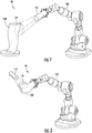
FIG. 1 is an exemplary embodiment of a robotic sensing apparatus; -
FIG. 2 is an exemplary embodiment of another robotic sensing apparatus; -
FIG. 3 is a flowchart outlining an exemplary method of sensor planning; and -
FIG. 4 is an exemplary embodiment of yet another robotic sensing apparatus. - Repeat use of reference characters in the present specification and drawings is intended to represent the same or analogous features or elements of the present invention.
- Reference now will be made in detail to embodiments of the invention, one or more examples of which are illustrated in the drawings. Each example is provided by way of explanation of the invention, not limitation of the invention. In fact, it will be apparent to those skilled in the art that various modifications and variations can be made in the present invention without departing from the scope of the invention as defined in the appended claims. For instance, features illustrated or described as part of one embodiment can be used with another embodiment to yield a still further embodiment. Thus, it is intended that the present invention covers such modifications and variations as come within the scope of the appended claims.
- As used herein, the terms "first", "second", and "third" may be used interchangeably to distinguish one component from another and are not intended to signify location or importance of the individual components.
- Robotic sensing apparatuses and methods of sensor planning that may capture samples of an area of interest while minimizing redundancy and time are generally provided. The methods and systems described herein may include steps or operations that may capture samples of an area of interest, such as a component, or assembly, or geographic area, at a desired resolution and level of completeness while minimizing the quantity of samples, such as images or measurements, taken to capture the area of interest. Various embodiments of the robotic sensing apparatuses and methods described herein may utilize a deep learning approach in conjunction with sensor planning. Furthermore, the systems and methods described herein may generally autonomously plan and capture a minimal quantity of samples to capture the area of interest at a desired level of completeness.
- Referring now to
FIGS. 1 and 2 , a robotic sensing apparatus for sensor planning 90 (herein referred to as "apparatus 90") includes one ormore sensors 110 acquiring samples of an area ofinterest 130. The one ormore sensors 110 may include an imaging device, a proximity sensor, or combinations thereof. In one embodiment, imaging devices may generally include cameras. In another embodiment, imaging devices may specifically include interferometers, such as, but not limited to, optical coherence tomography (e.g., white light scanners or blue light scanners). In other embodiments, the one ormore sensors 110 include proximity sensors, in which the proximity sensors may generally include sensors that may emit and/or retrieve electromagnetic signals and process changes in said electromagnetic signals. For example, proximity sensors may include, but are not limited to, capacitive, infrared, inductive, magnetic, sonic or ultrasonic proximity sensors, radar, LIDAR, or laser rangefinders. In various embodiments, the one ormore sensors 110 may include combinations of imaging devices and/or proximity sensors. In various embodiments, the one ormore sensors 110 acquire samples, including images or measurements, at various resolutions, angles, distances, orientations, sampling or measurement rates, frequencies, etc. - In one embodiment, the
apparatus 90 includes a translatable robotic apparatus 100 (herein referred to as "robot 100"). Therobot 100 may include a movable fixture, such as a robotic arm as shown inFIGS. 1 and 2 , or an autonomous mobile vehicle, such as a drone as shown inFIG. 4 . Translations of therobot 100, the one ormore sensors 110, and/or the area ofinterest 130 may include, but are not limited to, six-axis movements (e.g. up/down, side/side, forward/backward, etc.), pivots, turns, rotations, and/or displacements at constant or variable rates of motion. In the embodiments shown inFIGS. 1 and 2 , the sensor(s) 110 may be mounted to therobot 100 in which therobot 100 translates thesensor 110 tovarious portions 131 of an area ofinterest 130 at various angles or distances relative to the area ofinterest 130. - In other embodiments of the
apparatus 90, therobot 100 may translate the area ofinterest 130 relative to the one ormore sensors 110. For example, therobot 100, such as a robotic arm, may translate the area ofinterest 130 relative to one or morefixed sensors 110. Therobot 100 may translate the area ofinterest 130 to various distances, angles, and/or orientations relative to the one ormore sensors 110. - Referring now to
FIG. 3 , a flowchart outlining steps of an exemplary embodiment of a method of sensor planning 300 (herein referred to as "method 300") is generally provided. Themethod 300 shown inFIG. 3 may be implemented by theapparatus 90 shown and described in regard toFIGS. 1 and 2 . Themethod 300 may further be implemented by one or more computing devices, such as thecomputing device 120 described in regard toFIG. 4 .FIG. 3 depicts steps performed in a particular order for purposes of illustration and discussion. Those of ordinary skill in the art, using the disclosures provided herein, will understand that various steps of any of the methods disclosed herein can be modified, adapted, expanded, rearranged and/or omitted in various ways without deviating from the scope of the present disclosure. - The
method 300 can include at (310) defining, by one or more computing devices, an area of interest, at (320) identifying, by the one or more computing devices, one or more sensing parameters for the one or more sensors, at (330) determining, by the one or more computing devices, a sampling combination for acquiring a plurality of samples by the one or more sensors based at least in part on the one or more sensing parameters, and at (340) providing, by one or more computing devices, one or more command control signals to an apparatus including the one or more sensors to acquire the plurality of samples of the area of interest using the one or more sensors based at least on the sampling combination. - At (310), the
method 300 may include defining an area of interest. In one embodiment, defining an area of interest includes receiving a point cloud. Receiving a point cloud may include receiving an image file, such as a computer-aided design (CAD) file, of the area of interest. The image file may include a nominal file of the area of interest to which the samples from the sensors may measure in comparison. - In another embodiment, defining an area of interest may include defining a finite space in which a robot and/or one or more sensors may operate, such as the
robot 100 and/or one ormore sensors 110 shown inFIGS. 1, 2 , and4 . For example, the extent to which therobot 100 may translate may be spatially limited. In one example, therobot 100, as a robotic arm, may be limited in its range of motion, extension, etc. In another example, therobot 100, as a drone, may be geographically limited by coordinates, operating range, or operating envelope, such as altitude, speed, maneuverability, etc. Therefore, defining an area of interest may include defining a 2D or 3D space in which samples may be taken. - In still other embodiments, defining an area of interest may include taking a sample of the area of interest. For example, taking a sample of the area of interest may include taking a sample that broadly captures the area of interest, including a perimeter of the area of interest. Broadly capturing the area of interest may include sampling at a low resolution, or a large distance from the area of interest, or otherwise in minimal detail to obtain and define a periphery of the area of interest. In various embodiments, broadly capturing the area of interest may include capturing the defined spatial area as limited by coordinates, operating range, operating envelope, etc. In other embodiments, broadly capturing the area of interest may be dependent on a maximum sampling area of one or more sensors such that the area of interest may be defined by the one or more sensing parameters.
- At (320), the
method 300 includes identifying one or more sensing parameters for the one or more sensors. In one embodiment, identifying one or more sensing parameters may include defining one or more of a measurement resolution, a field of view, and/or a depth of field. Defining the measurement resolution may include defining a lateral resolution, a lens resolution, an image resolution, and/or a sensor resolution. Defining a sensor resolution may include defining a spatial and/or temporal sensor resolution. - In another embodiment, identifying one or more sensing parameters may include defining a total area covered by the one or more sensors. For example, defining a total area covered by the one or more sensors may be a function of one or more of the defined aforementioned resolutions. As another non-limiting example, such as shown and described in regard to
FIGS. 1, 2 , and4 , defining a total area covered may be approximately equal to or less than theportion 131 of the area ofinterest 130 captured by the one ormore sensors 110. In one embodiment, the total area covered by the one or more sensors may be a function of one or more of the defined aforementioned resolutions and additional user-defined limits based at least on a desired sample quality. For example, defining the total area covered may include defined hardware capabilities of the one or more sensors and a subset of said hardware capabilities based at least on a user-defined limitation. The user-defined limitation may be based generally on good visibility standards as defined by the user. Good visibility standards may be based at least on a measurement resolution, a field of view, and/or depth of field of the one or more sensors. - In still other embodiments at (320), identifying one or more sensing parameters may include calculating a curvature and/or normal vector of at least a portion of the area of interest. Calculating the curvature and/or normal vector may be based at least on a surface of the point cloud or image file defined in (310). The normal vector may define one or more sensor centers. For example, referring to
FIGS. 1 and 2 , the normal vector may define one or more centerlines 111 of the one ormore sensors 110 relative to theportion 131 of the area ofinterest 130. As another non-limiting example, the normal vector may define an angle of view 112 of thesensor 110 relative to the area ofinterest 130, or theportion 131 thereof. - At (330), the
method 300 includes determining a sampling combination for acquiring a plurality of samples by the one or more sensors based at least in part on the one or more sensing parameters. The sampling combination may be a combination of samples of the area of interest pursuant to capturing the area of interest. The combination of samples of the area of interest may include translations of the sensor(s) and/or the area of interest relative to one another. The sampling combination may further be a combination of sensing parameters relative to translations of the sensor(s) and/or the area of interest. In various embodiments, the sampling combination may include combinations of samples of various portions of the area of interest taken to capture the area of interest. For example, referring toFIGS. 1, 2 or4 , the sampling combination may include a specific sequence of translations and/or sensing parameters atvarious portions 131 of the area ofinterest 130 until the area ofinterest 130 is captured. The specific sequence of translations and/or sensing parameters may include distances, angles, and/or resolutions of the one ormore sensor 110 relative to the area ofinterest 130 for each sample captured of theportion 131 of the area ofinterest 130. - Determining a sampling combination to be acquired by the one or more sensors may further include determining a minimal quantity of samples to acquire to capture the area of interest. In one embodiment, determining a sampling combination to be acquired by the one or more sensors may include selecting the sampling combination based at least on a score function,

- In another embodiment, determining a sampling combination to be acquired by the one or more sensors may include at (332) determining a combination of overlap exponentials based at least on a reinforcement learning (RL) algorithm, at (334) calculating a score function for one or more sampling combinations based at least on a total area covered by the one or more sensors, an overlap perimeter, and the one or more overlap exponentials, and at (336) selecting the sampling combination corresponding to a maximum score function.
- At (332), the
method 300 may include using at least one of a State-Action-Result-State-Action (SARSA), Q-Learning, and Policy Gradient RL algorithm to determine a combination of overlap exponentials that may output a sampling combination that may minimize a quantity of samples taken of the area of interest pursuant to capturing the area of interest to a desired level of completeness. In various embodiments, at least one of the Q-Learning and Policy Gradient PL algorithms may be used in conjunction with a deep learning approach to determine a minimal quantity of samples for capturing the area of interest at a desired level of completeness. Determining the combination of overlap exponentials may include determining combinations of zero and non-zero overlap exponentials that may result in a maximum score function while capturing the area of interest in a minimal quantity of samples to a desired level of completeness. - At (340), the
method 300 includes acquiring the plurality of samples using the one or more sensors based at least on the sampling combination. In one embodiment, acquiring the plurality of samples may include translating the one or more sensor(s) and/or the area of interest relative to one another. For example, referring toFIGS. 1, 2 , or4 , the one ormore sensors 110 and/or the area ofinterest 130 may be mounted to therobot 100 and translate to capture samples at a plurality ofportions 131 of the area ofinterest 130 until the area ofinterest 130 is captured in desired detail and completeness. In another embodiment, themethod 300 may be implemented to determine positions, placements, setups, orientations, distances, etc. of one or more sensors relative to the area of interest using the determined sampling combination. For example, within the defined area of interest, such as a 2D or 3D space, the determined sampling combination may provide positions, placements, and orientations of sensors such that a minimal quantity of sensors is utilized to capture the area of interest within the 2D or 3D space to a desired level of detail and completeness. -
FIG. 4 depicts anexample apparatus 90 according to exemplary embodiments of the present disclosure. Theapparatus 90 can include one ormore sensors 110, arobot 100, and one ormore computing devices 120. In one embodiment, therobot 100 defines a robotic arm such as shown in regard toFIGS. 1 and 2 . In another embodiment, such as shown inFIG. 4 , therobot 100 defines an autonomous mobile vehicle, such as a drone. The one ormore sensors 120, therobot 100, and/or thecomputing device 120 can be configured to communicate via more or more network(s) 410, which can include any suitable wired and/or wireless communication links for transmission of the communications and/or data, as described herein. For instance, thenetwork 410 can include a SATCOM network, ACARS network, ARINC network, SITA network, AVICOM network, a VHF network, a HF network, a Wi-Fi network, a WiMAX network, a gatelink network, etc. - The computing device(s) 120 can include one or more processor(s) 121 and one or more memory device(s) 122. The one or more processor(s) 121 can include any suitable processing device, such as a microprocessor, microcontroller, integrated circuit, logic device, and/or other suitable processing device. The one or more memory device(s) 122 can include one or more computer-readable media, including, but not limited to, non-transitory computer-readable media, RAM, ROM, hard drives, flash drives, and/or other memory devices.
- The one or more memory device(s) 122 can store information accessible by the one or more processor(s) 121, including computer-
readable instructions 123 that can be executed by the one or more processor(s) 121. Theinstructions 123 can be any set of instructions that when executed by the one or more processor(s) 121, cause the one or more processor(s) 121 to perform operations. In some embodiments, theinstructions 123 can be executed by the one or more processor(s) 121 to cause the one or more processor(s) 121 to perform operations, such as any of the operations and functions for which the computing device(s) 120 are configured, the operations for sensor planning (e.g., method 300), as described herein, the operations for defining or receiving an area of interest, the operations for identifying or receiving one or more sensing parameters for the one or more sensors, the operations for determining a sampling combination for acquiring a plurality of samples by the one or more sensors based at least in part on the one or more sensing parameters, the operations for acquiring the plurality of samples of the area of interest using the one or more sensors based at least on the sampling combination, and/or any other operations or functions of the one or more computing device(s) 120. Theinstructions 123 can be software written in any suitable programming language or can be implemented in hardware. Additionally, and/or alternatively, theinstructions 123 can be executed in logically and/or virtually separate threads on processor(s) 121. The memory device(s) 122 can further storedata 124 that can be accessed by the processor(s) 121. For example, thedata 124 can include the one or more of the samples, the sampling combinations, the sensing parameters, the defined area of interest, the score function, the RL algorithm, the combinations of overlap exponentials, and/or any other data and/or information described herein. - The computing device(s) 120 can also include a
network interface 125 used to communicate, for example, with the other components of apparatus 90 (e.g., via network 410). Thenetwork interface 125 can include any suitable components for interfacing with one or more network(s), including for example, transmitters, receivers, ports, controllers, antennas, and/or other suitable components. - The technology discussed herein makes reference to computer-based systems and actions taken by and information sent to and from computer-based systems. One of ordinary skill in the art will recognize that the inherent flexibility of computer-based systems allows for a great variety of possible configurations, combinations, and divisions of tasks and functionality between and among components. For instance, processes discussed herein can be implemented using a single computing device or multiple computing devices working in combination. Databases, memory, instructions, and applications can be implemented on a single system or distributed across multiple systems. Distributed components can operate sequentially or in parallel.
- This written description uses examples to disclose the invention, including the best mode, and also to enable any person skilled in the art to practice the invention, including making and using any devices or systems and performing any incorporated methods. The patentable scope of the invention is defined by the claims.
Claims (15)
- A computer-implemented method of sensor planning (300) for acquiring samples via an apparatus (90) including one or more sensors (110), the computer-implemented method (300) comprising:defining (310), by one or more computing devices (120), an area of interest (130);identifying (320), by the one or more computing devices (120), one or more sensing parameters for the one or more sensors (110);determining (330), by the one or more computing devices (120), one or more sampling combinations for acquiring a plurality of samples of the area of interest by the one or more sensors (110) based at least in part on the one or more sensing parameters, comprising:determining (332), by one or more computing devices (120), a combination of overlap exponentials based at least on a reinforcement learning algorithm, wherein an overlap exponential is a factor by which overlap between the sample and a previous sample is encouraged;calculating (334), by one or more computing devices (120), a score function for the one or more sampling combinations based at least on a total area covered by the one or more sensors (110), an overlap perimeter, and the combination of overlap exponentials, wherein an overlap perimeter is a quantity of the sample that is redundant relative to a previous sample; andselecting (336), by one or more computing devices (120), the sampling combination corresponding to a maximum score function; andproviding (340), by the one or more computing devices (120), one or more command control signals to the apparatus (90) including the one or more sensors (110) to acquire the plurality of samples of the area of interest (130) using the one or more sensors (110) based at least on the sampling combination.
- The computer-implemented method (300) of claim 1, wherein the reinforcement learning algorithm comprises using at least one of a SARSA, Q-Learning, and Policy Gradient reinforcement learning algorithm.
- The computer-implemented method (300) of claim 1, wherein determining a combination of overlap exponentials based at least on a reinforcement learning algorithm comprises determining combinations of zero and non-zero overlap exponentials.
- The computer-implemented method (300) of claim 1, wherein determining a sampling combination for acquiring a plurality of samples by the one or more sensors (110) is based at least on a score function, wherein the score function is a function of at least one of a total area covered, an overlap perimeter, and an overlap exponential.
- The computer-implemented method (300) of claim 1, wherein identifying one or more sensing parameters includes calculating a curvature and/or normal vector of at least a portion (131) of the area of interest (130).
- The computer-implemented method (300) of claim 1, wherein identifying one or more sensing parameters includes defining a total area covered by the one or more sensors (110).
- The computer-implemented method (300) of claim 1, wherein identifying one or more sensing parameters includes defining one or more of a measurement resolution, a field of view, and/or a depth of field.
- The computer-implemented method (300) of claim 1, wherein defining an area of interest includes receiving a point cloud.
- The computer-implemented method (300) of claim 1, wherein defining an area of interest (130) includes defining a finite space in which the one or more sensors (110) operates.
- The computer-implemented method (300) of claim 1, wherein acquiring the plurality of samples includes translating one or more sensors (110) and/or translating the area of interest (130).
- The computer-implemented method (300) of claim 1, wherein identifying one or more sensing parameters includes defining one or more translations of the one or more sensors (110).
- The computer-implemented method (300) of claim 1, wherein the one or more sensors (110) is an imaging device, a proximity sensor, or a combination thereof.
- A robotic sensing apparatus (90) for sensor planning, the apparatus (90) comprising one or more sensors (110) and a computing device (120) comprising one or more processors (121) and one or more memory devices (122), the one or more memory devices (122) storing instructions (123) that when executed by the one or more processors (121) cause the one or more processors (121) to perform operations, the operations comprising:receiving an area of interest;receiving one or more sensing parameters for the one or more sensors;determining one or more sampling combinations for acquiring a plurality of samples of the area of interest by the one or more sensors, comprising:determining a combination of overlap exponentials based at least on a reinforcement learning algorithm, comprising determining combinations of zero and non-zero overlap exponentials, wherein an overlap exponential is a factor by which overlap between the sample and a previous sample is encouraged;calculating a score function for the one or more sampling combinations based at least on a total area covered by the one or more sensors, an overlap perimeter, and the combination of overlap exponentials, wherein an overlap perimeter is a quantity of the sample that is redundant relative to a previous sample; andselecting the sampling combination corresponding to a maximum score function; andacquiring the plurality of samples of the area of interest using the one or more sensors based at least on the sampling combination.
- The apparatus of claim 13, wherein determining a combination of overlap exponentials based at least on a reinforcement learning algorithm includes using a SARSA, Q-Learning, or Policy Gradient reinforcement learning algorithm.
- The apparatus of claim 13, wherein determining a combination of overlap exponentials based at least on a reinforcement learning algorithm includes determining combinations of zero and non-zero overlap exponentials.
Applications Claiming Priority (2)
| Application Number | Priority Date | Filing Date | Title |
|---|---|---|---|
| US15/342,500 US10265850B2 (en) | 2016-11-03 | 2016-11-03 | Robotic sensing apparatus and methods of sensor planning |
| PCT/US2017/056072 WO2018085013A1 (en) | 2016-11-03 | 2017-10-11 | Robotic sensing apparatus and methods of sensor planning |
Publications (2)
| Publication Number | Publication Date |
|---|---|
| EP3535096A1 EP3535096A1 (en) | 2019-09-11 |
| EP3535096B1 true EP3535096B1 (en) | 2020-09-02 |
Family
ID=60268449
Family Applications (1)
| Application Number | Title | Priority Date | Filing Date |
|---|---|---|---|
| EP17794817.1A Active EP3535096B1 (en) | 2016-11-03 | 2017-10-11 | Robotic sensing apparatus and methods of sensor planning |
Country Status (7)
| Country | Link |
|---|---|
| US (1) | US10265850B2 (en) |
| EP (1) | EP3535096B1 (en) |
| JP (1) | JP2019536143A (en) |
| CN (2) | CN110114193A (en) |
| BR (1) | BR112019008633A2 (en) |
| CA (1) | CA3041787A1 (en) |
| WO (1) | WO2018085013A1 (en) |
Families Citing this family (6)
| Publication number | Priority date | Publication date | Assignee | Title |
|---|---|---|---|---|
| WO2020083490A1 (en) * | 2018-10-25 | 2020-04-30 | Siemens Aktiengesellschaft | A method for computer-implemented determination of sensor positions in a simulated process of an automation system |
| CN109665114B (en) * | 2018-12-03 | 2022-04-12 | 中理检验有限公司 | Unmanned aerial vehicle cloud platform to sea water sample |
| CN110630596B (en) * | 2019-10-17 | 2020-04-17 | 山东大学 | Underwater redundant hydraulic mechanical arm and working method thereof |
| CN111823258B (en) * | 2020-07-16 | 2022-09-02 | 吉林大学 | Shear wave elasticity imaging detection mechanical arm |
| US11216005B1 (en) * | 2020-10-06 | 2022-01-04 | Accenture Global Solutions Limited | Generating a point cloud capture plan |
| CN114986488B (en) * | 2022-07-18 | 2023-05-05 | 佛山市科华智缝设备有限公司 | Manipulator is snatched to surface fabric contact pin |
Family Cites Families (20)
| Publication number | Priority date | Publication date | Assignee | Title |
|---|---|---|---|---|
| US4531192A (en) * | 1982-09-23 | 1985-07-23 | Crc Welding Systems, Inc. | Apparatus and method for sensing a workpiece with an electrical arc |
| US5831621A (en) * | 1996-10-21 | 1998-11-03 | The Trustees Of The University Of Pennyslvania | Positional space solution to the next best view problem |
| US20020169586A1 (en) | 2001-03-20 | 2002-11-14 | Rankin James Stewart | Automated CAD guided sensor planning process |
| US7111783B2 (en) | 2004-06-25 | 2006-09-26 | Board Of Trustees Operating Michigan State University | Automated dimensional inspection |
| JP4020144B2 (en) * | 2006-03-10 | 2007-12-12 | オムロン株式会社 | Inspection method of surface condition |
| US20080221733A1 (en) * | 2007-03-07 | 2008-09-11 | Kmt Robotic Solutions, Inc. | System and method of locating relative positions of objects |
| US20100030382A1 (en) * | 2008-07-31 | 2010-02-04 | University Of Medicine And Dentistry Of New Jersey | Inhalable particulate environmental robotic sampler |
| DE102008045387B4 (en) * | 2008-09-02 | 2017-02-09 | Carl Zeiss Ag | Apparatus and method for measuring a surface |
| US20110033254A1 (en) * | 2009-08-06 | 2011-02-10 | Kmt Robotic Solutions, Inc. | System And Method Of Locating Relative Positions Of Objects |
| KR101750340B1 (en) * | 2010-11-03 | 2017-06-26 | 엘지전자 주식회사 | Robot cleaner and controlling method of the same |
| WO2013116299A1 (en) * | 2012-01-31 | 2013-08-08 | 3M Innovative Properties Company | Method and apparatus for measuring the three dimensional structure of a surface |
| CN102721746A (en) * | 2012-07-04 | 2012-10-10 | 北京理工大学 | Double-manipulator ultrasonic transmission detection device |
| US9075415B2 (en) | 2013-03-11 | 2015-07-07 | Airphrame, Inc. | Unmanned aerial vehicle and methods for controlling same |
| US9393686B1 (en) * | 2013-03-15 | 2016-07-19 | Industrial Perception, Inc. | Moveable apparatuses having robotic manipulators and conveyors to facilitate object movement |
| JP6557227B2 (en) * | 2013-07-31 | 2019-08-07 | コーニンクレッカ フィリップス エヌ ヴェKoninklijke Philips N.V. | Treatment plan automation |
| JP6306903B2 (en) | 2014-03-06 | 2018-04-04 | キヤノン株式会社 | Information processing apparatus, information processing apparatus control method, and program |
| US9218646B1 (en) * | 2014-06-03 | 2015-12-22 | Mitsubishi Electric Research Laboratories, Inc. | Distributed path planning for mobile sensors |
| US10618174B2 (en) * | 2014-12-09 | 2020-04-14 | Aeolus Robotics, Inc. | Robotic Touch Perception |
| US9946259B2 (en) * | 2015-12-18 | 2018-04-17 | Raytheon Company | Negative obstacle detector |
| US10245724B2 (en) * | 2016-06-09 | 2019-04-02 | Shmuel Ur Innovation Ltd. | System, method and product for utilizing prediction models of an environment |
-
2016
- 2016-11-03 US US15/342,500 patent/US10265850B2/en active Active
-
2017
- 2017-10-11 JP JP2019522860A patent/JP2019536143A/en active Pending
- 2017-10-11 BR BR112019008633-1A patent/BR112019008633A2/en not_active IP Right Cessation
- 2017-10-11 EP EP17794817.1A patent/EP3535096B1/en active Active
- 2017-10-11 WO PCT/US2017/056072 patent/WO2018085013A1/en not_active Ceased
- 2017-10-11 CA CA3041787A patent/CA3041787A1/en not_active Abandoned
- 2017-10-11 CN CN201780080502.1A patent/CN110114193A/en active Pending
- 2017-10-11 CN CN202511110066.0A patent/CN120663329A/en active Pending
Non-Patent Citations (1)
| Title |
|---|
| None * |
Also Published As
| Publication number | Publication date |
|---|---|
| JP2019536143A (en) | 2019-12-12 |
| WO2018085013A1 (en) | 2018-05-11 |
| CA3041787A1 (en) | 2018-05-11 |
| US20180117760A1 (en) | 2018-05-03 |
| EP3535096A1 (en) | 2019-09-11 |
| US10265850B2 (en) | 2019-04-23 |
| CN110114193A (en) | 2019-08-09 |
| CN120663329A (en) | 2025-09-19 |
| BR112019008633A2 (en) | 2019-07-09 |
Similar Documents
| Publication | Publication Date | Title |
|---|---|---|
| US10265850B2 (en) | Robotic sensing apparatus and methods of sensor planning | |
| JP7297017B2 (en) | Method and apparatus for calibrating external parameters of on-board sensors and related vehicles | |
| US10970873B2 (en) | Method and device to determine the camera position and angle | |
| US10509983B2 (en) | Operating device, operating system, operating method, and program therefor | |
| US20220036574A1 (en) | System and method for obstacle avoidance | |
| CN108474653B (en) | Three-dimensional measurement device and measurement support processing method thereof | |
| EP3837492A1 (en) | Distance measuring method and device | |
| KR20190082291A (en) | Method and system for creating and updating vehicle environment map | |
| JP2016045150A (en) | Point group position data processing device, point group position data processing system, point group position data processing method, and program | |
| JP2012093811A (en) | Robot system and map update method | |
| WO2018046617A1 (en) | Method and system for calibrating multiple cameras | |
| CN111380510B (en) | Repositioning method and device and robot | |
| US10974730B2 (en) | Vehicle perception system on-line diangostics and prognostics | |
| CN114556438A (en) | 2D-to-3D line-based registration with unknown associations | |
| US11112780B2 (en) | Collaborative determination of a load footprint of a robotic vehicle | |
| US11562497B1 (en) | Automatic field of view detection | |
| US20200292319A1 (en) | Systems and methods for electronic mapping and localization within a facility | |
| CN109443345B (en) | Positioning method and system for monitoring navigation | |
| US20250036135A1 (en) | System and method for autonomous robotic map generation for targeted resolution and local accuracy | |
| JP5728564B2 (en) | Robot system and map updating method | |
| JP5953393B2 (en) | Robot system and map updating method | |
| KR20230082497A (en) | Method for real-time inspection of structures using 3d point cloud | |
| US20210156710A1 (en) | Map processing method, device, and computer-readable storage medium | |
| US20240329655A1 (en) | Information processing device, movable apparatus, information processing method, and storage medium | |
| US20250218039A1 (en) | Extrinsic calibration of a vehicle-mounted sensor using natural vehicle features |
Legal Events
| Date | Code | Title | Description |
|---|---|---|---|
| STAA | Information on the status of an ep patent application or granted ep patent |
Free format text: STATUS: UNKNOWN |
|
| STAA | Information on the status of an ep patent application or granted ep patent |
Free format text: STATUS: THE INTERNATIONAL PUBLICATION HAS BEEN MADE |
|
| PUAI | Public reference made under article 153(3) epc to a published international application that has entered the european phase |
Free format text: ORIGINAL CODE: 0009012 |
|
| STAA | Information on the status of an ep patent application or granted ep patent |
Free format text: STATUS: REQUEST FOR EXAMINATION WAS MADE |
|
| 17P | Request for examination filed |
Effective date: 20190501 |
|
| AK | Designated contracting states |
Kind code of ref document: A1 Designated state(s): AL AT BE BG CH CY CZ DE DK EE ES FI FR GB GR HR HU IE IS IT LI LT LU LV MC MK MT NL NO PL PT RO RS SE SI SK SM TR |
|
| AX | Request for extension of the european patent |
Extension state: BA ME |
|
| DAV | Request for validation of the european patent (deleted) | ||
| DAX | Request for extension of the european patent (deleted) | ||
| GRAP | Despatch of communication of intention to grant a patent |
Free format text: ORIGINAL CODE: EPIDOSNIGR1 |
|
| STAA | Information on the status of an ep patent application or granted ep patent |
Free format text: STATUS: GRANT OF PATENT IS INTENDED |
|
| RIC1 | Information provided on ipc code assigned before grant |
Ipc: B25J 9/16 20060101AFI20200228BHEP Ipc: G01B 11/24 20060101ALI20200228BHEP Ipc: G05D 1/00 20060101ALI20200228BHEP Ipc: G05B 19/401 20060101ALI20200228BHEP |
|
| INTG | Intention to grant announced |
Effective date: 20200316 |
|
| GRAS | Grant fee paid |
Free format text: ORIGINAL CODE: EPIDOSNIGR3 |
|
| GRAA | (expected) grant |
Free format text: ORIGINAL CODE: 0009210 |
|
| STAA | Information on the status of an ep patent application or granted ep patent |
Free format text: STATUS: THE PATENT HAS BEEN GRANTED |
|
| AK | Designated contracting states |
Kind code of ref document: B1 Designated state(s): AL AT BE BG CH CY CZ DE DK EE ES FI FR GB GR HR HU IE IS IT LI LT LU LV MC MK MT NL NO PL PT RO RS SE SI SK SM TR |
|
| REG | Reference to a national code |
Ref country code: GB Ref legal event code: FG4D |
|
| REG | Reference to a national code |
Ref country code: AT Ref legal event code: REF Ref document number: 1308299 Country of ref document: AT Kind code of ref document: T Effective date: 20200915 Ref country code: CH Ref legal event code: EP |
|
| REG | Reference to a national code |
Ref country code: DE Ref legal event code: R096 Ref document number: 602017022963 Country of ref document: DE |
|
| REG | Reference to a national code |
Ref country code: IE Ref legal event code: FG4D |
|
| REG | Reference to a national code |
Ref country code: LT Ref legal event code: MG4D |
|
| PG25 | Lapsed in a contracting state [announced via postgrant information from national office to epo] |
Ref country code: NO Free format text: LAPSE BECAUSE OF FAILURE TO SUBMIT A TRANSLATION OF THE DESCRIPTION OR TO PAY THE FEE WITHIN THE PRESCRIBED TIME-LIMIT Effective date: 20201202 Ref country code: SE Free format text: LAPSE BECAUSE OF FAILURE TO SUBMIT A TRANSLATION OF THE DESCRIPTION OR TO PAY THE FEE WITHIN THE PRESCRIBED TIME-LIMIT Effective date: 20200902 Ref country code: BG Free format text: LAPSE BECAUSE OF FAILURE TO SUBMIT A TRANSLATION OF THE DESCRIPTION OR TO PAY THE FEE WITHIN THE PRESCRIBED TIME-LIMIT Effective date: 20201202 Ref country code: FI Free format text: LAPSE BECAUSE OF FAILURE TO SUBMIT A TRANSLATION OF THE DESCRIPTION OR TO PAY THE FEE WITHIN THE PRESCRIBED TIME-LIMIT Effective date: 20200902 Ref country code: GR Free format text: LAPSE BECAUSE OF FAILURE TO SUBMIT A TRANSLATION OF THE DESCRIPTION OR TO PAY THE FEE WITHIN THE PRESCRIBED TIME-LIMIT Effective date: 20201203 Ref country code: LT Free format text: LAPSE BECAUSE OF FAILURE TO SUBMIT A TRANSLATION OF THE DESCRIPTION OR TO PAY THE FEE WITHIN THE PRESCRIBED TIME-LIMIT Effective date: 20200902 Ref country code: HR Free format text: LAPSE BECAUSE OF FAILURE TO SUBMIT A TRANSLATION OF THE DESCRIPTION OR TO PAY THE FEE WITHIN THE PRESCRIBED TIME-LIMIT Effective date: 20200902 |
|
| REG | Reference to a national code |
Ref country code: NL Ref legal event code: MP Effective date: 20200902 |
|
| REG | Reference to a national code |
Ref country code: AT Ref legal event code: MK05 Ref document number: 1308299 Country of ref document: AT Kind code of ref document: T Effective date: 20200902 |
|
| PG25 | Lapsed in a contracting state [announced via postgrant information from national office to epo] |
Ref country code: LV Free format text: LAPSE BECAUSE OF FAILURE TO SUBMIT A TRANSLATION OF THE DESCRIPTION OR TO PAY THE FEE WITHIN THE PRESCRIBED TIME-LIMIT Effective date: 20200902 Ref country code: PL Free format text: LAPSE BECAUSE OF FAILURE TO SUBMIT A TRANSLATION OF THE DESCRIPTION OR TO PAY THE FEE WITHIN THE PRESCRIBED TIME-LIMIT Effective date: 20200902 Ref country code: RS Free format text: LAPSE BECAUSE OF FAILURE TO SUBMIT A TRANSLATION OF THE DESCRIPTION OR TO PAY THE FEE WITHIN THE PRESCRIBED TIME-LIMIT Effective date: 20200902 |
|
| PG25 | Lapsed in a contracting state [announced via postgrant information from national office to epo] |
Ref country code: SM Free format text: LAPSE BECAUSE OF FAILURE TO SUBMIT A TRANSLATION OF THE DESCRIPTION OR TO PAY THE FEE WITHIN THE PRESCRIBED TIME-LIMIT Effective date: 20200902 Ref country code: CZ Free format text: LAPSE BECAUSE OF FAILURE TO SUBMIT A TRANSLATION OF THE DESCRIPTION OR TO PAY THE FEE WITHIN THE PRESCRIBED TIME-LIMIT Effective date: 20200902 Ref country code: RO Free format text: LAPSE BECAUSE OF FAILURE TO SUBMIT A TRANSLATION OF THE DESCRIPTION OR TO PAY THE FEE WITHIN THE PRESCRIBED TIME-LIMIT Effective date: 20200902 Ref country code: PT Free format text: LAPSE BECAUSE OF FAILURE TO SUBMIT A TRANSLATION OF THE DESCRIPTION OR TO PAY THE FEE WITHIN THE PRESCRIBED TIME-LIMIT Effective date: 20210104 Ref country code: EE Free format text: LAPSE BECAUSE OF FAILURE TO SUBMIT A TRANSLATION OF THE DESCRIPTION OR TO PAY THE FEE WITHIN THE PRESCRIBED TIME-LIMIT Effective date: 20200902 |
|
| PG25 | Lapsed in a contracting state [announced via postgrant information from national office to epo] |
Ref country code: AT Free format text: LAPSE BECAUSE OF FAILURE TO SUBMIT A TRANSLATION OF THE DESCRIPTION OR TO PAY THE FEE WITHIN THE PRESCRIBED TIME-LIMIT Effective date: 20200902 Ref country code: AL Free format text: LAPSE BECAUSE OF FAILURE TO SUBMIT A TRANSLATION OF THE DESCRIPTION OR TO PAY THE FEE WITHIN THE PRESCRIBED TIME-LIMIT Effective date: 20200902 Ref country code: ES Free format text: LAPSE BECAUSE OF FAILURE TO SUBMIT A TRANSLATION OF THE DESCRIPTION OR TO PAY THE FEE WITHIN THE PRESCRIBED TIME-LIMIT Effective date: 20200902 Ref country code: IS Free format text: LAPSE BECAUSE OF FAILURE TO SUBMIT A TRANSLATION OF THE DESCRIPTION OR TO PAY THE FEE WITHIN THE PRESCRIBED TIME-LIMIT Effective date: 20210102 |
|
| REG | Reference to a national code |
Ref country code: CH Ref legal event code: PL |
|
| REG | Reference to a national code |
Ref country code: DE Ref legal event code: R097 Ref document number: 602017022963 Country of ref document: DE |
|
| PG25 | Lapsed in a contracting state [announced via postgrant information from national office to epo] |
Ref country code: MC Free format text: LAPSE BECAUSE OF FAILURE TO SUBMIT A TRANSLATION OF THE DESCRIPTION OR TO PAY THE FEE WITHIN THE PRESCRIBED TIME-LIMIT Effective date: 20200902 Ref country code: SK Free format text: LAPSE BECAUSE OF FAILURE TO SUBMIT A TRANSLATION OF THE DESCRIPTION OR TO PAY THE FEE WITHIN THE PRESCRIBED TIME-LIMIT Effective date: 20200902 Ref country code: LU Free format text: LAPSE BECAUSE OF NON-PAYMENT OF DUE FEES Effective date: 20201011 |
|
| PLBE | No opposition filed within time limit |
Free format text: ORIGINAL CODE: 0009261 |
|
| STAA | Information on the status of an ep patent application or granted ep patent |
Free format text: STATUS: NO OPPOSITION FILED WITHIN TIME LIMIT |
|
| REG | Reference to a national code |
Ref country code: BE Ref legal event code: MM Effective date: 20201031 |
|
| 26N | No opposition filed |
Effective date: 20210603 |
|
| PG25 | Lapsed in a contracting state [announced via postgrant information from national office to epo] |
Ref country code: CH Free format text: LAPSE BECAUSE OF NON-PAYMENT OF DUE FEES Effective date: 20201031 Ref country code: BE Free format text: LAPSE BECAUSE OF NON-PAYMENT OF DUE FEES Effective date: 20201031 Ref country code: DK Free format text: LAPSE BECAUSE OF FAILURE TO SUBMIT A TRANSLATION OF THE DESCRIPTION OR TO PAY THE FEE WITHIN THE PRESCRIBED TIME-LIMIT Effective date: 20200902 Ref country code: LI Free format text: LAPSE BECAUSE OF NON-PAYMENT OF DUE FEES Effective date: 20201031 Ref country code: SI Free format text: LAPSE BECAUSE OF FAILURE TO SUBMIT A TRANSLATION OF THE DESCRIPTION OR TO PAY THE FEE WITHIN THE PRESCRIBED TIME-LIMIT Effective date: 20200902 |
|
| PG25 | Lapsed in a contracting state [announced via postgrant information from national office to epo] |
Ref country code: IE Free format text: LAPSE BECAUSE OF NON-PAYMENT OF DUE FEES Effective date: 20201011 Ref country code: IT Free format text: LAPSE BECAUSE OF FAILURE TO SUBMIT A TRANSLATION OF THE DESCRIPTION OR TO PAY THE FEE WITHIN THE PRESCRIBED TIME-LIMIT Effective date: 20200902 |
|
| PG25 | Lapsed in a contracting state [announced via postgrant information from national office to epo] |
Ref country code: TR Free format text: LAPSE BECAUSE OF FAILURE TO SUBMIT A TRANSLATION OF THE DESCRIPTION OR TO PAY THE FEE WITHIN THE PRESCRIBED TIME-LIMIT Effective date: 20200902 Ref country code: MT Free format text: LAPSE BECAUSE OF FAILURE TO SUBMIT A TRANSLATION OF THE DESCRIPTION OR TO PAY THE FEE WITHIN THE PRESCRIBED TIME-LIMIT Effective date: 20200902 Ref country code: CY Free format text: LAPSE BECAUSE OF FAILURE TO SUBMIT A TRANSLATION OF THE DESCRIPTION OR TO PAY THE FEE WITHIN THE PRESCRIBED TIME-LIMIT Effective date: 20200902 |
|
| PG25 | Lapsed in a contracting state [announced via postgrant information from national office to epo] |
Ref country code: MK Free format text: LAPSE BECAUSE OF FAILURE TO SUBMIT A TRANSLATION OF THE DESCRIPTION OR TO PAY THE FEE WITHIN THE PRESCRIBED TIME-LIMIT Effective date: 20200902 |
|
| P01 | Opt-out of the competence of the unified patent court (upc) registered |
Effective date: 20230411 |
|
| PG25 | Lapsed in a contracting state [announced via postgrant information from national office to epo] |
Ref country code: NL Free format text: LAPSE BECAUSE OF NON-PAYMENT OF DUE FEES Effective date: 20200923 |
|
| PGFP | Annual fee paid to national office [announced via postgrant information from national office to epo] |
Ref country code: GB Payment date: 20250923 Year of fee payment: 9 |
|
| PGFP | Annual fee paid to national office [announced via postgrant information from national office to epo] |
Ref country code: FR Payment date: 20250924 Year of fee payment: 9 |
|
| PGFP | Annual fee paid to national office [announced via postgrant information from national office to epo] |
Ref country code: DE Payment date: 20250923 Year of fee payment: 9 |