EP3534546A1 - A filtering device for power line communication - Google Patents
A filtering device for power line communication Download PDFInfo
- Publication number
- EP3534546A1 EP3534546A1 EP18159256.9A EP18159256A EP3534546A1 EP 3534546 A1 EP3534546 A1 EP 3534546A1 EP 18159256 A EP18159256 A EP 18159256A EP 3534546 A1 EP3534546 A1 EP 3534546A1
- Authority
- EP
- European Patent Office
- Prior art keywords
- contact
- pass filter
- low
- frequency
- filtering device
- Prior art date
- Legal status (The legal status is an assumption and is not a legal conclusion. Google has not performed a legal analysis and makes no representation as to the accuracy of the status listed.)
- Granted
Links
Images



Classifications
-
- H—ELECTRICITY
- H04—ELECTRIC COMMUNICATION TECHNIQUE
- H04B—TRANSMISSION
- H04B3/00—Line transmission systems
- H04B3/54—Systems for transmission via power distribution lines
-
- H—ELECTRICITY
- H04—ELECTRIC COMMUNICATION TECHNIQUE
- H04B—TRANSMISSION
- H04B3/00—Line transmission systems
- H04B3/54—Systems for transmission via power distribution lines
- H04B3/56—Circuits for coupling, blocking, or by-passing of signals
-
- H—ELECTRICITY
- H04—ELECTRIC COMMUNICATION TECHNIQUE
- H04B—TRANSMISSION
- H04B2203/00—Indexing scheme relating to line transmission systems
- H04B2203/54—Aspects of powerline communications not already covered by H04B3/54 and its subgroups
- H04B2203/5462—Systems for power line communications
- H04B2203/5491—Systems for power line communications using filtering and bypassing
Definitions
- the present invention generally relates to power line communication systems, and more specifically to the improvement of power line communication between different power line branches.
- a power line communication system uses existing electrical wiring to provide communication channels between various distributed locations. For example, in a domestic electrical installation the existing wiring is utilised to let a computer in a bedroom communicate with a router connected to the internet which is situated in a living room. Thus, besides power carrying currents the electrical wiring in the electrical installation may also carry communication signals.
- an adapter in a socket of the bedroom communicates with an adapter in a socket of the living room.
- the power line branch to which the socket in the bedroom is connected differs from the power line branch to which the socket in the living room is connected.
- These power line branches are each protected by a fuse and/or a circuit breaker.
- several other power line branches are present in a real-life domestic electrical installation, such as one for a bathroom and one for a kitchen.
- a filtering device for filtering communication channels on a power line branch in a power line communication network, the filtering device having a first and a second contact, the filtering device comprising a switch configured to switch between a pass-through mode and a filtering mode, wherein:
- the power line branch may carry both communication channels and power carrying current.
- the frequency of a power carrying current is in the range of 50Hz, for example in Europe, and in the range of 60Hz, for example in the United States, while home-control power line communication systems typically operate in the frequency range of 20 to 200MHz. This latter range may differ depending on a used standard, nevertheless, it should be clear that the frequency range of communication channels in a power line communication network is significantly higher compared to the frequency range of power carrying currents.
- the filtering device is configured to filter the communication channels on the power branch.
- the frequency range of the communications channels for example in the range of 20 to 200MHz, is filtered or blocked, while the frequencies lower than this range are passed through.
- the filtering is performed by the use of a first low-pass filter with a cut-off frequency of, for example, 20MHz or even lower. This cut-off frequency may differ depending on the used the power line communication standard. Frequencies lower than this cut-off frequency are passed through, while frequencies higher than this cut-off frequency are blocked. Furthermore, the cut-off frequency may also be adjusted in such a way that one or more higher frequency communication channels are blocked, while other lower ones are passed through.
- the filtering device further comprises a switch configured to switch between the filtering mode on the one hand and the pass-through mode on the other hand.
- the first low-pass filter thus filters the communication channels
- the pass-through mode the low-pass filter is bypassed.
- the switch either guides both the communication channels and the power carrying current through the low-pass filter or bypasses the filter.
- the first and second contacts are directly connected by, for example, a wire, while in the filtering mode the low-pass filter connects the contacts to each other.
- the switch may be configured to interrupt the current and communication channels under load.
- the switching may further, for example, be performed manually.
- An advantage of the filtering device is that the electrical installation which is used for power line communication may be adapted in such a way that communication channels are attenuated in power branches which are not deployed for power line communication and the desired path is not.
- power branches are, for example, branches which supply power to a bathroom or a basement and are generally not used in a power line communication network.
- the communication channels are not attenuated, such that the power line communication network within the electrical installation is set up in an optimal manner.
- the filtering device further comprises a trigger module configured to trigger the switch based on a control signal.
- the switching is initiated by the trigger module.
- the initiation of the triggering is based on a control signal.
- the trigger module may further comprise an interface configured to receive said control signal.
- the control signal is, for example, a pulse or a wireless signal.
- the switch may be managed remotely, such that an intervention is performed in a fast manner when, for example, a set-up of the power line communication network needs to be changed or adapted.
- the trigger module is further configured to receive the control signal through the first and/or second contact.
- the control signal is either imposed on the first or second contact or on both.
- the trigger module which receives the control signal is then configured to block the power carrying current and communication channels such that there is no additional connection between both contacts of the filtering device thereby bridging the functioning of the filtering device.
- This is, for example, achieved by combining a low-pass filter with a high-pass filter in the trigger module adapted to the frequency of the low-frequency control channel.
- the low-frequency control channel may be imposed in the electrical installation without interfering with neither the power carrying current nor the communication channels of the power line communication network. Secondly, there is no further need for additional wiring to trigger the trigger module.
- control signal is a low-frequency control signal having a frequency lower than the cut-off frequency of the first low-pass filter.
- the trigger module may also be triggered by a low-frequency control signal, which comprises a frequency higher than the frequency of the power carrying current and lower than the frequencies of the communication channels. In this way, no interference between the communication channels on the one hand and the low-frequency control signal on the other hand occurs.
- the filtering device is further configured to adjust the cut-off frequency of the first-low pass filter such that one or more communication channels are passed through in the filtering mode.
- the filtering device and more specifically the first-low pass filter may be adapted to the power line communication network such that the device is suitable for a variety of standards of power line communication systems.
- the cut-off frequency is adapted thereby anticipation to the communication channels which will be present in the electrical installation.
- the filtering device is configured to adjust the cut-off frequency based on a load in the power line communication network.
- the cut-off frequency of the first low-pass filter may be adapted during operation of the power line communication system such that an adaption to a changing load is performed in a fast manner.
- the disclosure relates to a protecting device for protecting a power line branch in a power line communication network, the protecting device comprising an interrupting module having a first and a second contact and triggerable when an overcurrent and/or overload is detected, the protecting device further comprising the filtering device according to the first aspect of the disclosure, and wherein the first contact of the interrupting module is connected to the first contact of the filtering device, and wherein the first contact of the interrupting module and the second contact of the filtering device corresponds to a first and a second output contact of the protecting device.
- the filtering device is connected in series with a fuse or a circuit breaker or any other interrupting module suitable for interrupting an overcurrent and/or overload in a circuit.
- the protecting device comprises the filtering device and the interrupting module such that it may be easily installed in the electrical installation in order to protect a power line branch.
- the protecting device has thus two output contacts, whereby one may be connected to a power source and the other one to the power branch that is protected by the device itself. In this way, the set-up of the electrical installation and adaption to a power line communication network is performed in a fast and straightforward way.
- the protecting device further comprises a second low-pass filter and a high-pass filter, and wherein the second low-pass filter and the high-pass filter each comprise a source port and a filtered port, and wherein the source ports are connected to the second contact of the interrupting module, and wherein the filtered port of the second low-pass filter and the second contact of the filtering device corresponds to a first and a second output contact of the protecting device.
- the second low-pass filter is connected in series with the interrupting module and the filtering device.
- the filtering device comprises a fixed low-pass filter, the second low-pass filter, on one side and a switchable low-pass filter, the first low-pass filter, on the other side.
- Communication channels originating from the side of the second low-pass filter are in this way continually filtered, while at the other side, the side of the first low-pass filter, the channels are filtered depending on the position of the switch.
- the high-pass filter is connected to the second low-pass filter and the interrupting module. In other words, the high-pass filter is branched off from the connection between the interrupting module and the second low-pass filter.
- the high-pass filter thus branches off and guides communication channels from the interrupting module to its filtered port which corresponds to a second output of the protecting device. This second output may then be connected to a corresponding output of a second protecting device. Additionally, more than one high-pass filters may be present such that they are placed in, for example, a daisy chain.
- a cut-off frequency of the second low-pass filter corresponds to a power current frequency
- the cut-off frequency of the second low-pass filter corresponds either to 50Hz or 60Hz depending on the region wherein the protecting device is deployed.
- a cut-off frequency of the second low-pass filter is lower than the cut-off frequency of the first low-pass filter.
- the cut-off frequency of the second low-pass filter may also have a different value than the frequency of the power carrying current, whereby it is lower than the cut-off frequency of the first low-pass filter.
- the disclosure relates to an electric switchboard for directing electrical power from a power source to one or more power line branches, the electric switchboard comprising at least two of the protecting devices according to the second aspect of the disclosure, wherein the filtered ports of the second low-pass filters of the protecting devices are connected to the power source, and wherein the filtered ports of the first high-pass filters of the first protecting device are connected to each other.
- a plurality of protecting devices are thus deployed in the electrical installation such that this electrical installation may be adapted to a power line communication network in an optimized manner.
- the electric switchboard further comprises a dynamic spectrum management module configured to generate the control signals of each of the trigger modules.
- each of the protecting devices and more in particular the trigger modules thereof may be managed remotely by the dynamic spectrum management module. Furthermore, in this way an accurate overview of the electrical installation with respect to the power line communication network is obtained.
- the invention relates to a filtering device for filtering communication channels on a power line branch in a power line communication network.
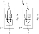
- Figures 1 a and 1 b schematically illustrate such a device.
- the filtering device 100 comprises two contacts 102 and 103 to connect the device 100 to an electrical circuit.
- the device 100 further comprises a switch 104 and a first low-pass filter 110.
- the filtering device 100 is configured to be set in either a pass-through mode 112 or a filtering mode 111, which are respectively schematically illustrated by Fig. 1a and 1 b.
- the switch 104 is switched.
- the contacts 102 and 103 are directly connected to each-other, for example, by an electrical wire.
- the contacts are connected to each-other with a wire comprising a low ohmic resistance such that signals and/or current are passed through without attenuating them, or at least minimizing any attenuation.
- the electrical wire is thus, for example, a copper wire.
- the contacts 102 and 103 are connected to each-other by the first low-pass filter 110.
- the first low-pass filter 110 comprises two contacts from which one is connected to contact 102 through, for example, a copper wire, and a second contact of the first low-pass filter 110 is connected to contact 103. In this way, signals and/or current flowing from contact 102 to 103 or vice versa are guided through the first low-pass filter 110.
- the filtering device comprises, according to an embodiment, a trigger module.
- the trigger module 200 incorporated in the filtering device 201, and schematically illustrated in the filtering mode 111, triggers the switch 104 based on a control signal.
- the triggering implies that the filtering device 201 switches between the filtering mode 111 and the pass-through mode 112.
- This control signal may, for example, be received by one of the contacts 102 and 103, as illustrated by the dashed lines. Alternatively, the control signal may also be received through an interface and/or external contact. It should furthermore be clear that the trigger module 200, when receiving the control signal through contacts 102 and/or 103 does not introduce an additional connection between the contacts 102 and 103.
- the protecting device 300 further comprises an interrupting module 301 having a first 302 and a second 303 contact and the interrupting module 301 is configured to interrupt a current flowing from the first 302 to the second 303 contact or vice versa, when an overload and/or overcurrent is detected.
- an overcurrent may, for example, be caused by a short circuit.
- One contact of the interrupting module 301 is connected to a contact of the filtering device 201.
- the contact 303 of the interrupting module 301 is connected to the contact 102 of the filtering device 201.
- the other contact 302 of the interrupting module 301 and the other contact 103 of the filtering device 201 are then the outer connecting contacts such that the protecting device 300 may be placed in series with a power branch.
- the protecting device may further, according to an embodiment, comprises a second low-pass filter and a high-pass filter, as schematically illustrated by Fig. 4 .
- the protecting device 400 comprises, besides the filtering device 201 and the interrupting module 301, the second low-pass filter 401 and the high-pass filter 402.
- the second low-pass filter 401 as well as the high-pass filter 402 both comprise a source port, respectively 404 and 403, and a filtered port, respectively 405 and 406.
- the source ports 404 and 403 are connected to the contact 302 of the interrupting module 301.
- the filtered ports 405 and 406 are then replacing the contact 302 of the interrupting module 301 as the outer contact of the protecting device 400.
- three outer contacts 103, 405 and 406 are present.
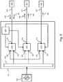
- FIG. 5 schematically represents an electric switchboard.
- the electric switchboard 541 is, for example, a domestic electric switchboard to provide electric power in rooms of a house.
- the electric switchboard 541 and the electrical installation connected to it is utilized for power line communication between different devices in the house.
- the electric switchboard 541 illustrated by Fig. 5 comprises three protecting devices as schematically illustrated in Fig. 4 , namely protecting device 400, 500, and 510.
- Each protecting device comprises three output contacts, but a protecting device according to device 300 may also be combined therewith.
- these output contacts are 103, 405, and 406, which correspond to the contacts as illustrated in Fig. 4 .
- the protecting device 500 has a first output contact 503, which corresponds to the contact of a filtering device incorporated in the protecting device 500.
- the second output contact 501 corresponds to the filtered port of a high-pass filter incorporated in the protecting device 500.
- the third output contact 502 corresponds to the filtered port of a second low-pass filter incorporated in the protecting device 500.
- the protecting device 510 has a first output contact 513, which corresponds to the contact of a filtering device incorporated in the protecting device 510.
- the second output contact 511 corresponds to the filtered port of a high-pass filter incorporated in the protecting device 510.
- the third output contact 512 corresponds to the filtered port of a second low-pass filter incorporated in the protecting device 510.
- the electric switchboard 541 further comprises a busbar 542 which is on one side connected to an electric power source 540.
- power branches are branched off.
- These power branches as illustrated by power branches 520, 521, and 522, direct electric power from the source 540 to sockets and other power ports in the house.
- the number of power branches in a house depends on the configuration thereof but comprises in real-life situations generally more than three branches. Nevertheless, in this illustration, three power branches are represented, wherein, for example, power branch 520 directs current to a home office 530, power branch 521 directs current to a living room 531, and power branch 522 directs current to a kitchen 532.
- the flow of electric currents is not illustrated, but it is obvious to the skilled person that electric power from the source 540, via the busbar 542 flows to electric devices in the different rooms 530, 531, and 532 through a closed circuit.
- sockets are present connected to the power branch 520.
- a router connected to the internet is present as well. This router is, for example, connected to a telephony line when using a digital subscriber line, DSL, or to an infrastructure of cable television when using cable internet access, or any other network used to provide internet access. Anyhow, it should be clear that the internet connection is a separate connection and initially not connected to the power branch 520.
- a smart tv is present and is connected to the internet through a wire.
- the smart tv in the living room 531 is connected to the router in the home office 530 from an internet access point of view.
- This connection is carry out using a power line communication system.
- custom made adapters are used and connected to sockets of both the home office 530 and the living room 531.
- an adapter in a socket in the home office 530 exchanges data packets with an adapter in a socket in the living room 531.
- no internet connection is present.
- the interrupting devices 400, 500, and 510 are set in such a way that the connection between the adapted in the home office 530 and the adapter in the living room 531 is optimal from a communication signal point of view.
- the filtering devices of interrupting devices 400 and 500 are set in the pass-through mode, while the filtering device of interrupting module 510 is set in the filtering mode.
- the filtering devices may also be placed in series with the power branches between an interrupting device on one side, and sockets and/or power ports on the other side.
- Communication channels originating from the router in the home office 530 and represented by arrow 560 are guided through the protecting device 400.
- the communication signals are thus first received at contact 103. Since the filtering device 201 of protecting device 400 is in the pass-through mode, the communication channels are directly guided to contact 102, and thus not through the low-pass filter 110.
- the communication channels are guided through the interrupting module 301. In the embodiment of the interrupting device according to Fig. 3 , the communication channels are then guided into the bus bar 542. Through the bus bar 542, the communication channels are distributed over the difference power branches to communicate with devices connected through custom made adapters.
- the interrupting devices 400, 500, and 510 comprises each a second low-pass filter and a high-pass filter.
- the filtering devices of interrupting devices 400 and 500 are set in the pass-through mode and the filtering device of interrupting device 510 in its filtering mode.
- communication signals received at contact 302 of the interrupting module 301 of interrupting device 400 are guided through the high-pass filter 402 and blocked by the second low-pass filter 401.
- the communication channels are presents.
- the cut-off frequency of the first and/or second low pass filters as set such that frequencies of power carrying current are passed through. This is illustrated in Figure 6 .
- the cut-off frequency may thus, for example, be set at 30MHz, but this cut-off frequency may be adapted depending on the used power line communication system standard.
- the frequencies in the range illustrated by 601 are then passed through, while the frequencies in the range illustrated by 602 are attenuated and ideally blocked.
- the filtering devices of the interrupting devices 400, 500, and 510 may be manually set is the mode as already discussed. This is, for example, advantageously when in advance it is known between which power branches the communication channels needs be guided, and when the configuration will be maintained over a long-time period.
- the switching may also be performed through the trigger module, for example for interrupting device 400 by trigger module 200.
- the triggering may then be performed by a dynamic management module 550, which generated control signals to trigger each of the trigger modules of interrupting devices 400, 500, and 510.
- Such a control signals is, for example, a radio signal and is illustrated by dashed lines originating from the dynamic spectrum management module 550.
- a control signal may also originate from devices located in 530, 531 and/or 532 and be guided through over contacts 103, 503 and/or 513.
- control signals may also be generated by, for example, the router in the home office 530 or any other device suitable to generate control signals to trigger the trigger modules.
- the generated control signals are then injected in the power branches.
- a control signal is, for example, illustrated by arrow 561, which is directed to the different trigger modules of the interrupting devices, and thus to the power branches of the electrical installation.
- the received control signal is illustrated by arrow 563, while the received control signal received in power branch 522 is illustrated by arrow 564.
- control signals 561, 563, and 564 are not attenuated by first and/or second low-pass filter. In this way, a full control is maintained over the trigger modules.
- the frequencies of the control signals are thus, for example, within the frequency range 601 as illustrated in Fig. 6 .
- top, bottom, over, under, and the like are introduced for descriptive purposes and not necessarily to denote relative positions. It is to be understood that the terms so used are interchangeable under appropriate circumstances and embodiments of the invention are capable of operating according to the present invention in other sequences, or in orientations different from the one(s) described or illustrated above.
Landscapes
- Engineering & Computer Science (AREA)
- Power Engineering (AREA)
- Computer Networks & Wireless Communication (AREA)
- Signal Processing (AREA)
- Cable Transmission Systems, Equalization Of Radio And Reduction Of Echo (AREA)
Abstract
Description
- The present invention generally relates to power line communication systems, and more specifically to the improvement of power line communication between different power line branches.
- A power line communication system uses existing electrical wiring to provide communication channels between various distributed locations. For example, in a domestic electrical installation the existing wiring is utilised to let a computer in a bedroom communicate with a router connected to the internet which is situated in a living room. Thus, besides power carrying currents the electrical wiring in the electrical installation may also carry communication signals.
- Often, existing connection points in the electrical installation, such as sockets, are used to inject these communication signals by the use of custom made adapters. Accordingly, an adapter in a socket of the bedroom communicates with an adapter in a socket of the living room. Generally, the power line branch to which the socket in the bedroom is connected differs from the power line branch to which the socket in the living room is connected. These power line branches are each protected by a fuse and/or a circuit breaker. Moreover, besides a power line branch for the living room and one for a bedroom, several other power line branches are present in a real-life domestic electrical installation, such as one for a bathroom and one for a kitchen.
- As a result, communication signals exchanged between the adapters of the bedroom and the living room will not only pass through the protecting devices of their respective power line branches but will also be present or exposed to other power line branches of the domestic electrical installation.
- It is however a drawback that communication signals within a power line communication system are transmitted to all power line branches. Since the communication signals are attenuated in this way, there is the necessity of an additional functioning of the power line communication system to amplify the communication signals. Besides, electrical devices may cause noise signals injected on the power line branch to which they are connected thereby deteriorating the functioning of the power line communication system.
- It is therefore an object to overcome the above identified drawbacks and to provide a solution for optimizing a power line communication system.
- This object is achieved, in a first aspect, by a filtering device for filtering communication channels on a power line branch in a power line communication network, the filtering device having a first and a second contact, the filtering device comprising a switch configured to switch between a pass-through mode and a filtering mode, wherein:
- in the pass-through mode the first contact is directly connected with the second contact and configured to pass through a power current frequency and the communication channels; and
- in the filtering mode the first contact is connected with the second contact through a first low pass filter and wherein a cut-off frequency of the first low-pass filter is configured to pass through the power carrying current and to block one or more of the communication channels.
- The power line branch may carry both communication channels and power carrying current. The frequency of a power carrying current is in the range of 50Hz, for example in Europe, and in the range of 60Hz, for example in the United States, while home-control power line communication systems typically operate in the frequency range of 20 to 200MHz. This latter range may differ depending on a used standard, nevertheless, it should be clear that the frequency range of communication channels in a power line communication network is significantly higher compared to the frequency range of power carrying currents.
- The filtering device is configured to filter the communication channels on the power branch. In other words, the frequency range of the communications channels, for example in the range of 20 to 200MHz, is filtered or blocked, while the frequencies lower than this range are passed through. The filtering is performed by the use of a first low-pass filter with a cut-off frequency of, for example, 20MHz or even lower. This cut-off frequency may differ depending on the used the power line communication standard. Frequencies lower than this cut-off frequency are passed through, while frequencies higher than this cut-off frequency are blocked. Furthermore, the cut-off frequency may also be adjusted in such a way that one or more higher frequency communication channels are blocked, while other lower ones are passed through.
- The filtering device further comprises a switch configured to switch between the filtering mode on the one hand and the pass-through mode on the other hand. In the filtering mode, the first low-pass filter thus filters the communication channels, while in the pass-through mode, the low-pass filter is bypassed. Differently formulated, the switch either guides both the communication channels and the power carrying current through the low-pass filter or bypasses the filter. In the pass-through mode the first and second contacts are directly connected by, for example, a wire, while in the filtering mode the low-pass filter connects the contacts to each other.
- The switch may be configured to interrupt the current and communication channels under load. The switching may further, for example, be performed manually.
- An advantage of the filtering device is that the electrical installation which is used for power line communication may be adapted in such a way that communication channels are attenuated in power branches which are not deployed for power line communication and the desired path is not. Such power branches are, for example, branches which supply power to a bathroom or a basement and are generally not used in a power line communication network. In other power branches, the communication channels are not attenuated, such that the power line communication network within the electrical installation is set up in an optimal manner.
- According to an embodiment, the filtering device further comprises a trigger module configured to trigger the switch based on a control signal.
- Thus, the switching is initiated by the trigger module. The initiation of the triggering is based on a control signal. The trigger module may further comprise an interface configured to receive said control signal. The control signal is, for example, a pulse or a wireless signal. In this way, the switch may be managed remotely, such that an intervention is performed in a fast manner when, for example, a set-up of the power line communication network needs to be changed or adapted.
- According to an embodiment, the trigger module is further configured to receive the control signal through the first and/or second contact.
- The control signal is either imposed on the first or second contact or on both. The trigger module which receives the control signal is then configured to block the power carrying current and communication channels such that there is no additional connection between both contacts of the filtering device thereby bridging the functioning of the filtering device. This is, for example, achieved by combining a low-pass filter with a high-pass filter in the trigger module adapted to the frequency of the low-frequency control channel. Advantageously, the low-frequency control channel may be imposed in the electrical installation without interfering with neither the power carrying current nor the communication channels of the power line communication network. Secondly, there is no further need for additional wiring to trigger the trigger module.
- According to an embodiment, the control signal is a low-frequency control signal having a frequency lower than the cut-off frequency of the first low-pass filter.
- Thus, besides a pulse or a wireless signal, the trigger module may also be triggered by a low-frequency control signal, which comprises a frequency higher than the frequency of the power carrying current and lower than the frequencies of the communication channels. In this way, no interference between the communication channels on the one hand and the low-frequency control signal on the other hand occurs.
- According to an embodiment, the filtering device is further configured to adjust the cut-off frequency of the first-low pass filter such that one or more communication channels are passed through in the filtering mode.
- In other words, the filtering device and more specifically the first-low pass filter may be adapted to the power line communication network such that the device is suitable for a variety of standards of power line communication systems. Thus, prior to the bring into service of the communication network, the cut-off frequency is adapted thereby anticipation to the communication channels which will be present in the electrical installation.
- According to an embodiment, the filtering device is configured to adjust the cut-off frequency based on a load in the power line communication network.
- Additionally, the cut-off frequency of the first low-pass filter may be adapted during operation of the power line communication system such that an adaption to a changing load is performed in a fast manner.
- According to a second aspect, the disclosure relates to a protecting device for protecting a power line branch in a power line communication network, the protecting device comprising an interrupting module having a first and a second contact and triggerable when an overcurrent and/or overload is detected, the protecting device further comprising the filtering device according to the first aspect of the disclosure, and wherein the first contact of the interrupting module is connected to the first contact of the filtering device, and wherein the first contact of the interrupting module and the second contact of the filtering device corresponds to a first and a second output contact of the protecting device.
- In other words, the filtering device is connected in series with a fuse or a circuit breaker or any other interrupting module suitable for interrupting an overcurrent and/or overload in a circuit. The protecting device comprises the filtering device and the interrupting module such that it may be easily installed in the electrical installation in order to protect a power line branch. The protecting device has thus two output contacts, whereby one may be connected to a power source and the other one to the power branch that is protected by the device itself. In this way, the set-up of the electrical installation and adaption to a power line communication network is performed in a fast and straightforward way.
- According to an embodiment, the protecting device further comprises a second low-pass filter and a high-pass filter, and wherein the second low-pass filter and the high-pass filter each comprise a source port and a filtered port, and wherein the source ports are connected to the second contact of the interrupting module, and wherein the filtered port of the second low-pass filter and the second contact of the filtering device corresponds to a first and a second output contact of the protecting device.
- In other words, the second low-pass filter is connected in series with the interrupting module and the filtering device. In this way, the filtering device comprises a fixed low-pass filter, the second low-pass filter, on one side and a switchable low-pass filter, the first low-pass filter, on the other side. Communication channels originating from the side of the second low-pass filter are in this way continually filtered, while at the other side, the side of the first low-pass filter, the channels are filtered depending on the position of the switch. Next, the high-pass filter is connected to the second low-pass filter and the interrupting module. In other words, the high-pass filter is branched off from the connection between the interrupting module and the second low-pass filter. The high-pass filter thus branches off and guides communication channels from the interrupting module to its filtered port which corresponds to a second output of the protecting device. This second output may then be connected to a corresponding output of a second protecting device. Additionally, more than one high-pass filters may be present such that they are placed in, for example, a daisy chain.
- According to an embodiment, a cut-off frequency of the second low-pass filter corresponds to a power current frequency.
- In other words, the cut-off frequency of the second low-pass filter corresponds either to 50Hz or 60Hz depending on the region wherein the protecting device is deployed.
- According to an embodiment, a cut-off frequency of the second low-pass filter is lower than the cut-off frequency of the first low-pass filter.
- The cut-off frequency of the second low-pass filter may also have a different value than the frequency of the power carrying current, whereby it is lower than the cut-off frequency of the first low-pass filter.
- According to a third aspect, the disclosure relates to an electric switchboard for directing electrical power from a power source to one or more power line branches, the electric switchboard comprising at least two of the protecting devices according to the second aspect of the disclosure, wherein the filtered ports of the second low-pass filters of the protecting devices are connected to the power source, and wherein the filtered ports of the first high-pass filters of the first protecting device are connected to each other.
- A plurality of protecting devices are thus deployed in the electrical installation such that this electrical installation may be adapted to a power line communication network in an optimized manner.
- According to an embodiment, the electric switchboard further comprises a dynamic spectrum management module configured to generate the control signals of each of the trigger modules.
- Advantageously, each of the protecting devices and more in particular the trigger modules thereof may be managed remotely by the dynamic spectrum management module. Furthermore, in this way an accurate overview of the electrical installation with respect to the power line communication network is obtained.
-
-
Fig. 1 a illustrates a filtering device in a pass-through mode andFig.1b illustrates the filtering device in a filtering mode according to an embodiment of the invention; and -
Fig. 2 illustrates a filtering device comprising a trigger module according to an embodiment of the invention; and -
Fig. 3 illustrates a protecting device comprising a filtering device according to an embodiment of the invention; and -
Fig. 4 illustrates a protecting device comprising a filtering device, a low-pass filter and a high-pass filter according to an embodiment of the invention; and -
Fig. 5 illustrates an electric switchboard comprising protecting devices and filtering devices according to an embodiment of the invention; and -
Fig. 6 illustrates a gain-magnitude frequency response of a first-order low-pass filter incorporated in a filtering device according to an embodiment of the invention. - According to an embodiment, the invention relates to a filtering device for filtering communication channels on a power line branch in a power line communication network.
Figures 1 a and 1 b schematically illustrate such a device. Thefiltering device 100 comprises twocontacts device 100 to an electrical circuit. Thedevice 100 further comprises aswitch 104 and a first low-pass filter 110. - The
filtering device 100 is configured to be set in either a pass-throughmode 112 or afiltering mode 111, which are respectively schematically illustrated byFig. 1a and 1 b. To change between themodes switch 104 is switched. In the pass-throughmode 112 thecontacts mode 112 the contacts are connected to each-other with a wire comprising a low ohmic resistance such that signals and/or current are passed through without attenuating them, or at least minimizing any attenuation. The electrical wire is thus, for example, a copper wire. - In the
filtering mode 111, thecontacts pass filter 110. The first low-pass filter 110 comprises two contacts from which one is connected to contact 102 through, for example, a copper wire, and a second contact of the first low-pass filter 110 is connected to contact 103. In this way, signals and/or current flowing fromcontact 102 to 103 or vice versa are guided through the first low-pass filter 110. - As illustrated in
Figure 2 , the filtering device comprises, according to an embodiment, a trigger module. Thetrigger module 200 incorporated in thefiltering device 201, and schematically illustrated in thefiltering mode 111, triggers theswitch 104 based on a control signal. The triggering implies that thefiltering device 201 switches between thefiltering mode 111 and the pass-throughmode 112. This control signal may, for example, be received by one of thecontacts trigger module 200, when receiving the control signal throughcontacts 102 and/or 103 does not introduce an additional connection between thecontacts - The
filtering device Figure 3 . The protectingdevice 300 comprises thefiltering device 201, which on its behalf comprises atrigger module 200, but is should be obvious that the protectingdevice 300 may also comprises afiltering device 100 without atrigger module 200. - The protecting
device 300 further comprises an interruptingmodule 301 having a first 302 and a second 303 contact and the interruptingmodule 301 is configured to interrupt a current flowing from the first 302 to the second 303 contact or vice versa, when an overload and/or overcurrent is detected. Such an overcurrent may, for example, be caused by a short circuit. - One contact of the interrupting
module 301 is connected to a contact of thefiltering device 201. In this illustration ofFig. 3 thecontact 303 of the interruptingmodule 301 is connected to thecontact 102 of thefiltering device 201. Theother contact 302 of the interruptingmodule 301 and theother contact 103 of thefiltering device 201 are then the outer connecting contacts such that the protectingdevice 300 may be placed in series with a power branch. - The protecting device may further, according to an embodiment, comprises a second low-pass filter and a high-pass filter, as schematically illustrated by
Fig. 4 . The protectingdevice 400 comprises, besides thefiltering device 201 and the interruptingmodule 301, the second low-pass filter 401 and the high-pass filter 402. The second low-pass filter 401 as well as the high-pass filter 402 both comprise a source port, respectively 404 and 403, and a filtered port, respectively 405 and 406. Thesource ports contact 302 of the interruptingmodule 301. The filteredports contact 302 of the interruptingmodule 301 as the outer contact of the protectingdevice 400. Thus, in the embodiment of the protectingdevice 400, threeouter contacts - The filtering operation of the
filtering device 201 incorporated in the protectingdevice 400 will now be further explained byFigure 5 , which schematically represents an electric switchboard. Theelectric switchboard 541 is, for example, a domestic electric switchboard to provide electric power in rooms of a house. In this exemplary illustration, theelectric switchboard 541 and the electrical installation connected to it, is utilized for power line communication between different devices in the house. - The
electric switchboard 541 illustrated byFig. 5 comprises three protecting devices as schematically illustrated inFig. 4 , namely protectingdevice device 300 may also be combined therewith. For the protectingdevice 400, these output contacts are 103, 405, and 406, which correspond to the contacts as illustrated inFig. 4 . - The protecting
device 500 has afirst output contact 503, which corresponds to the contact of a filtering device incorporated in the protectingdevice 500. Thesecond output contact 501 corresponds to the filtered port of a high-pass filter incorporated in the protectingdevice 500. Thethird output contact 502 corresponds to the filtered port of a second low-pass filter incorporated in the protectingdevice 500. - The protecting
device 510 has afirst output contact 513, which corresponds to the contact of a filtering device incorporated in the protectingdevice 510. Thesecond output contact 511 corresponds to the filtered port of a high-pass filter incorporated in the protectingdevice 510. Thethird output contact 512 corresponds to the filtered port of a second low-pass filter incorporated in the protectingdevice 510. - The
electric switchboard 541 further comprises abusbar 542 which is on one side connected to anelectric power source 540. At the other side of thebus bar 542 power branches are branched off. These power branches, as illustrated bypower branches source 540 to sockets and other power ports in the house. The number of power branches in a house depends on the configuration thereof but comprises in real-life situations generally more than three branches. Nevertheless, in this illustration, three power branches are represented, wherein, for example,power branch 520 directs current to ahome office 530,power branch 521 directs current to aliving room 531, andpower branch 522 directs current to akitchen 532. The flow of electric currents is not illustrated, but it is obvious to the skilled person that electric power from thesource 540, via thebusbar 542 flows to electric devices in thedifferent rooms - In the
home office 530 sockets are present connected to thepower branch 520. Furthermore, in the home office 530 a router connected to the internet is present as well. This router is, for example, connected to a telephony line when using a digital subscriber line, DSL, or to an infrastructure of cable television when using cable internet access, or any other network used to provide internet access. Anyhow, it should be clear that the internet connection is a separate connection and initially not connected to thepower branch 520. - In the living room 531 a smart tv is present and is connected to the internet through a wire. In other words, the smart tv in the
living room 531 is connected to the router in thehome office 530 from an internet access point of view. This connection is carry out using a power line communication system. To achieve this, custom made adapters are used and connected to sockets of both thehome office 530 and theliving room 531. In other words, an adapter in a socket in thehome office 530 exchanges data packets with an adapter in a socket in theliving room 531. In thekitchen 532 no internet connection is present. - Given this scheme, the interrupting
devices home office 530 and the adapter in theliving room 531 is optimal from a communication signal point of view. - The filtering devices of interrupting
devices module 510 is set in the filtering mode. According to an embodiment, the filtering devices may also be placed in series with the power branches between an interrupting device on one side, and sockets and/or power ports on the other side. - Communication channels originating from the router in the
home office 530 and represented byarrow 560 are guided through the protectingdevice 400. With reference toFig. 4 , the communication signals are thus first received atcontact 103. Since thefiltering device 201 of protectingdevice 400 is in the pass-through mode, the communication channels are directly guided to contact 102, and thus not through the low-pass filter 110. Next, the communication channels are guided through the interruptingmodule 301. In the embodiment of the interrupting device according toFig. 3 , the communication channels are then guided into thebus bar 542. Through thebus bar 542, the communication channels are distributed over the difference power branches to communicate with devices connected through custom made adapters. In thekitchen 532 such an adapter is not present, such that a filtering device placed in series in thepower branch 522 is set in its filtering mode. In this way, communication channels originating from thebus bar 542 are blocked for thepower branch 522. On the other hand, since the smart tv in theliving room 531 is configured to receive communication channels, illustrated byarrow 562, the filtering device in series withpower branch 521 is set in its pass-through mode. - According to the embodiments illustrated in
Fig. 4 andFig. 5 , the interruptingdevices Fig. 5 , with communication channels originating from thehome office 530 and illustrated byarrow 560 are guided to theliving room 531 and illustrated byarrow 562. Thus, the filtering devices of interruptingdevices device 510 in its filtering mode. Thus, communication signals received atcontact 302 of the interruptingmodule 301 of interruptingdevice 400 are guided through the high-pass filter 402 and blocked by the second low-pass filter 401. Thus, atoutput contact 406 the communication channels are presents. On the other hand, power carrying current atcontact 302 are guided through the second low-pass filter 401 and blocked by the high-pass filter 402. Next, contact 406 is connected tocontacts devices respective output contacts device 510 is set in the filtering mode, the communication channels are blocked to thekitchen 532, while the filtering device of interruptingdevice 500 is set in the pass-through mode and thus the communication channels are guided to theliving room 531. - To block the communication channels and pass through the power carrying currents, the cut-off frequency of the first and/or second low pass filters as set such that frequencies of power carrying current are passed through. This is illustrated in
Figure 6 . The cut-off frequency may thus, for example, be set at 30MHz, but this cut-off frequency may be adapted depending on the used power line communication system standard. The frequencies in the range illustrated by 601 are then passed through, while the frequencies in the range illustrated by 602 are attenuated and ideally blocked. - The filtering devices of the interrupting
devices device 400 bytrigger module 200. The triggering may then be performed by adynamic management module 550, which generated control signals to trigger each of the trigger modules of interruptingdevices spectrum management module 550. - A control signal may also originate from devices located in 530, 531 and/or 532 and be guided through over
contacts - The control signals may also be generated by, for example, the router in the
home office 530 or any other device suitable to generate control signals to trigger the trigger modules. The generated control signals are then injected in the power branches. A control signal is, for example, illustrated byarrow 561, which is directed to the different trigger modules of the interrupting devices, and thus to the power branches of the electrical installation. Inpower branch 521, the received control signal is illustrated byarrow 563, while the received control signal received inpower branch 522 is illustrated byarrow 564. - Contrary to the communication channels, the control signals 561, 563, and 564 are not attenuated by first and/or second low-pass filter. In this way, a full control is maintained over the trigger modules. The frequencies of the control signals are thus, for example, within the
frequency range 601 as illustrated inFig. 6 . - Although the present invention has been illustrated by reference to specific embodiments, it will be apparent to those skilled in the art that the invention is not limited to the details of the foregoing illustrative embodiments, and that the present invention may be embodied with various changes and modifications without departing from the scope thereof. The present embodiments are therefore to be considered in all respects as illustrative and not restrictive, the scope of the invention being indicated by the appended claims rather than by the foregoing description, and all changes which come within the scope of the claims are therefore intended to be embraced therein.
- It will furthermore be understood by the reader of this patent application that the words "comprising" or "comprise" do not exclude other elements or steps, that the words "a" or "an" do not exclude a plurality, and that a single element, such as a computer system, a processor, or another integrated unit may fulfil the functions of several means recited in the claims. Any reference signs in the claims shall not be construed as limiting the respective claims concerned. The terms "first", "second", third", "a", "b", "c", and the like, when used in the description or in the claims are introduced to distinguish between similar elements or steps and are not necessarily describing a sequential or chronological order. Similarly, the terms "top", "bottom", "over", "under", and the like are introduced for descriptive purposes and not necessarily to denote relative positions. It is to be understood that the terms so used are interchangeable under appropriate circumstances and embodiments of the invention are capable of operating according to the present invention in other sequences, or in orientations different from the one(s) described or illustrated above.
Claims (12)
- A filtering device (100) for filtering communication channels on a power line branch in a power line communication network, the filtering device (100) having a first (102) and a second (103) contact, the filtering device (100) comprising a switch (104) configured to switch between a pass-through mode (110) and a filtering mode (111), wherein:- in the pass-through mode (112) the first contact (102) is directly connected with the second (103) contact and configured to pass through a power current frequency and the communication channels; and- in the filtering mode (111) the first contact (102) is connected with the second contact (103) through a first low-pass filter (110) and wherein a cut-off frequency (600) of the first low-pass filter (110) is configured to pass through (601) the power carrying current and to block (602) one or more of the communication channels.
- The filtering device (201) according to claim 1, further comprising a trigger module (200) configured to trigger the switch (104) based on a control signal.
- The filtering device (201) according to claim 2, wherein the trigger module (200) is further configured to receive the control signal through the first (102) and/or second (103) contact.
- The filtering device (201) according to claim 3, wherein the control signal is a low-frequency control signal having a frequency lower than the cut-off frequency (600) of the first low-pass filter (110).
- The filtering device (100, 201) according to claim 4, further configured to adjust the cut-off frequency (600) of the first low-pass filter (110) such that one or more communication channels are pass through in the filtering mode (111).
- The filtering device (100, 201) according to claim 5, further configured to adjust the cut-off frequency (600) based on a load in the power line communication network.
- A protecting device (300) for protecting a power line branch in a power line communication network, the protecting device (300) comprising an interrupting module (301) having a first (302) and a second (303) contact and triggerable when an overcurrent and/or overload is detected, the protecting device (300) further comprising the filtering device (100) according to any of the preceding claims, and wherein the first contact (302) of the interrupting module (301) is connected to the first contact (102) of the filtering device, and wherein the first contact (302) of the interrupting module (301) and the second contact (103) of the filtering device (100) corresponds to a first (302) and a second (103) output contact of the protecting device (300).
- The protecting device (400) according to claim 7, further comprising a second low-pass filter (401) and a high-pass filter (402), and wherein the second low-pass filter (401) and the high-pass filter (402) each comprise a source port (403, 404) and a filtered port (405, 406), and wherein the source ports (403, 404) are connected to the second contact (302) of the interrupting module (301), and wherein the filtered port 405) of the second low-pass filter (401) and the second contact (103) of the filtering device (100) correspond to a first (405) and a second (103) output contact of the protecting device (400).
- The protecting device (400) according to claim 8, wherein a cut-off frequency of the second low-pass filter (401) corresponds to a power current frequency.
- The protecting device (300) according to claim 8, wherein a cut-off frequency of the second low-pass filter (401) is lower than the cut-off frequency of the first low-pass filter (110).
- An electric switchboard (541) for directing electrical power from a power source (540) to one or more power line branches (520, 521, 522), the electric switchboard (541) comprising at least two of the protecting devices (400, 500, 510) according to claim 8, wherein the filtered ports (405, 502, 512) of the second low-pass filters of the protecting devices (400, 500, 510) are connected to the power source (540), and wherein the filtered ports (406, 501, 511) of the first high-pass filters of the first protecting device (400, 500, 510) are connected to each other.
- The electric switch board (541) according to claim 11, further comprising a dynamic spectrum management module (550) configured to generate the control signals of each of the trigger modules.
Priority Applications (1)
| Application Number | Priority Date | Filing Date | Title |
|---|---|---|---|
| EP18159256.9A EP3534546B1 (en) | 2018-02-28 | 2018-02-28 | A filtering device for power line communication |
Applications Claiming Priority (1)
| Application Number | Priority Date | Filing Date | Title |
|---|---|---|---|
| EP18159256.9A EP3534546B1 (en) | 2018-02-28 | 2018-02-28 | A filtering device for power line communication |
Publications (2)
| Publication Number | Publication Date |
|---|---|
| EP3534546A1 true EP3534546A1 (en) | 2019-09-04 |
| EP3534546B1 EP3534546B1 (en) | 2021-09-29 |
Family
ID=61569056
Family Applications (1)
| Application Number | Title | Priority Date | Filing Date |
|---|---|---|---|
| EP18159256.9A Active EP3534546B1 (en) | 2018-02-28 | 2018-02-28 | A filtering device for power line communication |
Country Status (1)
| Country | Link |
|---|---|
| EP (1) | EP3534546B1 (en) |
Citations (2)
| Publication number | Priority date | Publication date | Assignee | Title |
|---|---|---|---|---|
| US20030156370A1 (en) * | 2002-02-20 | 2003-08-21 | Alps Electric Co., Ltd. | Power distribution panel capable of transmitting data and wired telecommunication network system including the same |
| WO2010100952A1 (en) * | 2009-03-06 | 2010-09-10 | パナソニック株式会社 | Power supply device |
-
2018
- 2018-02-28 EP EP18159256.9A patent/EP3534546B1/en active Active
Patent Citations (2)
| Publication number | Priority date | Publication date | Assignee | Title |
|---|---|---|---|---|
| US20030156370A1 (en) * | 2002-02-20 | 2003-08-21 | Alps Electric Co., Ltd. | Power distribution panel capable of transmitting data and wired telecommunication network system including the same |
| WO2010100952A1 (en) * | 2009-03-06 | 2010-09-10 | パナソニック株式会社 | Power supply device |
Also Published As
| Publication number | Publication date |
|---|---|
| EP3534546B1 (en) | 2021-09-29 |
Similar Documents
| Publication | Publication Date | Title |
|---|---|---|
| MX2012008468A (en) | Circuit breaker panel. | |
| EP0663127A1 (en) | Shared common in-house wiring to permit multiple telephone carriers to serve the same customer | |
| HU225568B1 (en) | Local network forming part of a cable tv system | |
| PL174402B1 (en) | Method of and apparatus for supplying power to a network of concentric cables | |
| EP2614632B1 (en) | System for providing telephony and data services | |
| US6707913B1 (en) | Network interface | |
| JP4184978B2 (en) | Measuring device and telecommunication assembly | |
| EP0302246A1 (en) | Communication system with an ISDN terminal connector for different ISDN interfaces in an ISDN switching network | |
| EP3534546A1 (en) | A filtering device for power line communication | |
| CN112581739B (en) | Electricity meter and adapter module therefor | |
| JP4583642B2 (en) | Distribution board with lightning arrester | |
| CA2531838C (en) | Subscriber line testing system, broadband line card and broadband/narrowband telecommunication system | |
| US7944704B2 (en) | Terminal module with integrated functions | |
| WO2018055409A2 (en) | Multiplexing apparatus and method of use thereof | |
| RU2353071C1 (en) | Telecommunication module, and assembly containing telecommunication module | |
| EP3078075B1 (en) | Antenna multiplexing apparatus with bypass paths and method of use thereof | |
| EP1135923B3 (en) | Signal distribution system for the distribution and transfer of communication and multimedia signals | |
| US8233503B2 (en) | Arrangement and method relating to subscriber line connections | |
| US20070183446A1 (en) | Broadband and narrowband service processing apparatus in communication equipment and its implementation method | |
| CA1251584A (en) | Digital signal cross-connection system | |
| US20060256931A1 (en) | Contact bank measurement arrangement including a contact bank telecommunications module provided with contact bank or a measurement arrangement and telecommunications assembly including plural modules | |
| US8093744B2 (en) | Power mains distribution panel data link | |
| EP0898817A1 (en) | Power line communication employing cordless telephone standard | |
| US20190229517A1 (en) | Circuit breaker for power line communication | |
| JP3996578B2 (en) | Method and system for transmitting a carrier signal between first and second antenna networks |
Legal Events
| Date | Code | Title | Description |
|---|---|---|---|
| PUAI | Public reference made under article 153(3) epc to a published international application that has entered the european phase |
Free format text: ORIGINAL CODE: 0009012 |
|
| STAA | Information on the status of an ep patent application or granted ep patent |
Free format text: STATUS: THE APPLICATION HAS BEEN PUBLISHED |
|
| AK | Designated contracting states |
Kind code of ref document: A1 Designated state(s): AL AT BE BG CH CY CZ DE DK EE ES FI FR GB GR HR HU IE IS IT LI LT LU LV MC MK MT NL NO PL PT RO RS SE SI SK SM TR |
|
| AX | Request for extension of the european patent |
Extension state: BA ME |
|
| STAA | Information on the status of an ep patent application or granted ep patent |
Free format text: STATUS: REQUEST FOR EXAMINATION WAS MADE |
|
| 17P | Request for examination filed |
Effective date: 20200304 |
|
| RBV | Designated contracting states (corrected) |
Designated state(s): AL AT BE BG CH CY CZ DE DK EE ES FI FR GB GR HR HU IE IS IT LI LT LU LV MC MK MT NL NO PL PT RO RS SE SI SK SM TR |
|
| GRAP | Despatch of communication of intention to grant a patent |
Free format text: ORIGINAL CODE: EPIDOSNIGR1 |
|
| STAA | Information on the status of an ep patent application or granted ep patent |
Free format text: STATUS: GRANT OF PATENT IS INTENDED |
|
| INTG | Intention to grant announced |
Effective date: 20210429 |
|
| GRAS | Grant fee paid |
Free format text: ORIGINAL CODE: EPIDOSNIGR3 |
|
| GRAA | (expected) grant |
Free format text: ORIGINAL CODE: 0009210 |
|
| STAA | Information on the status of an ep patent application or granted ep patent |
Free format text: STATUS: THE PATENT HAS BEEN GRANTED |
|
| AK | Designated contracting states |
Kind code of ref document: B1 Designated state(s): AL AT BE BG CH CY CZ DE DK EE ES FI FR GB GR HR HU IE IS IT LI LT LU LV MC MK MT NL NO PL PT RO RS SE SI SK SM TR |
|
| REG | Reference to a national code |
Ref country code: GB Ref legal event code: FG4D |
|
| REG | Reference to a national code |
Ref country code: DE Ref legal event code: R096 Ref document number: 602018024122 Country of ref document: DE |
|
| REG | Reference to a national code |
Ref country code: CH Ref legal event code: EP Ref country code: AT Ref legal event code: REF Ref document number: 1435129 Country of ref document: AT Kind code of ref document: T Effective date: 20211015 |
|
| REG | Reference to a national code |
Ref country code: IE Ref legal event code: FG4D |
|
| REG | Reference to a national code |
Ref country code: LT Ref legal event code: MG9D |
|
| PG25 | Lapsed in a contracting state [announced via postgrant information from national office to epo] |
Ref country code: NO Free format text: LAPSE BECAUSE OF FAILURE TO SUBMIT A TRANSLATION OF THE DESCRIPTION OR TO PAY THE FEE WITHIN THE PRESCRIBED TIME-LIMIT Effective date: 20211229 Ref country code: BG Free format text: LAPSE BECAUSE OF FAILURE TO SUBMIT A TRANSLATION OF THE DESCRIPTION OR TO PAY THE FEE WITHIN THE PRESCRIBED TIME-LIMIT Effective date: 20211229 Ref country code: LT Free format text: LAPSE BECAUSE OF FAILURE TO SUBMIT A TRANSLATION OF THE DESCRIPTION OR TO PAY THE FEE WITHIN THE PRESCRIBED TIME-LIMIT Effective date: 20210929 Ref country code: SE Free format text: LAPSE BECAUSE OF FAILURE TO SUBMIT A TRANSLATION OF THE DESCRIPTION OR TO PAY THE FEE WITHIN THE PRESCRIBED TIME-LIMIT Effective date: 20210929 Ref country code: RS Free format text: LAPSE BECAUSE OF FAILURE TO SUBMIT A TRANSLATION OF THE DESCRIPTION OR TO PAY THE FEE WITHIN THE PRESCRIBED TIME-LIMIT Effective date: 20210929 Ref country code: FI Free format text: LAPSE BECAUSE OF FAILURE TO SUBMIT A TRANSLATION OF THE DESCRIPTION OR TO PAY THE FEE WITHIN THE PRESCRIBED TIME-LIMIT Effective date: 20210929 Ref country code: HR Free format text: LAPSE BECAUSE OF FAILURE TO SUBMIT A TRANSLATION OF THE DESCRIPTION OR TO PAY THE FEE WITHIN THE PRESCRIBED TIME-LIMIT Effective date: 20210929 |
|
| REG | Reference to a national code |
Ref country code: NL Ref legal event code: MP Effective date: 20210929 |
|
| REG | Reference to a national code |
Ref country code: AT Ref legal event code: MK05 Ref document number: 1435129 Country of ref document: AT Kind code of ref document: T Effective date: 20210929 |
|
| PG25 | Lapsed in a contracting state [announced via postgrant information from national office to epo] |
Ref country code: LV Free format text: LAPSE BECAUSE OF FAILURE TO SUBMIT A TRANSLATION OF THE DESCRIPTION OR TO PAY THE FEE WITHIN THE PRESCRIBED TIME-LIMIT Effective date: 20210929 Ref country code: GR Free format text: LAPSE BECAUSE OF FAILURE TO SUBMIT A TRANSLATION OF THE DESCRIPTION OR TO PAY THE FEE WITHIN THE PRESCRIBED TIME-LIMIT Effective date: 20211230 |
|
| PG25 | Lapsed in a contracting state [announced via postgrant information from national office to epo] |
Ref country code: AT Free format text: LAPSE BECAUSE OF FAILURE TO SUBMIT A TRANSLATION OF THE DESCRIPTION OR TO PAY THE FEE WITHIN THE PRESCRIBED TIME-LIMIT Effective date: 20210929 |
|
| PG25 | Lapsed in a contracting state [announced via postgrant information from national office to epo] |
Ref country code: IS Free format text: LAPSE BECAUSE OF FAILURE TO SUBMIT A TRANSLATION OF THE DESCRIPTION OR TO PAY THE FEE WITHIN THE PRESCRIBED TIME-LIMIT Effective date: 20220129 Ref country code: SK Free format text: LAPSE BECAUSE OF FAILURE TO SUBMIT A TRANSLATION OF THE DESCRIPTION OR TO PAY THE FEE WITHIN THE PRESCRIBED TIME-LIMIT Effective date: 20210929 Ref country code: RO Free format text: LAPSE BECAUSE OF FAILURE TO SUBMIT A TRANSLATION OF THE DESCRIPTION OR TO PAY THE FEE WITHIN THE PRESCRIBED TIME-LIMIT Effective date: 20210929 Ref country code: PT Free format text: LAPSE BECAUSE OF FAILURE TO SUBMIT A TRANSLATION OF THE DESCRIPTION OR TO PAY THE FEE WITHIN THE PRESCRIBED TIME-LIMIT Effective date: 20220131 Ref country code: PL Free format text: LAPSE BECAUSE OF FAILURE TO SUBMIT A TRANSLATION OF THE DESCRIPTION OR TO PAY THE FEE WITHIN THE PRESCRIBED TIME-LIMIT Effective date: 20210929 Ref country code: NL Free format text: LAPSE BECAUSE OF FAILURE TO SUBMIT A TRANSLATION OF THE DESCRIPTION OR TO PAY THE FEE WITHIN THE PRESCRIBED TIME-LIMIT Effective date: 20210929 Ref country code: ES Free format text: LAPSE BECAUSE OF FAILURE TO SUBMIT A TRANSLATION OF THE DESCRIPTION OR TO PAY THE FEE WITHIN THE PRESCRIBED TIME-LIMIT Effective date: 20210929 Ref country code: EE Free format text: LAPSE BECAUSE OF FAILURE TO SUBMIT A TRANSLATION OF THE DESCRIPTION OR TO PAY THE FEE WITHIN THE PRESCRIBED TIME-LIMIT Effective date: 20210929 Ref country code: CZ Free format text: LAPSE BECAUSE OF FAILURE TO SUBMIT A TRANSLATION OF THE DESCRIPTION OR TO PAY THE FEE WITHIN THE PRESCRIBED TIME-LIMIT Effective date: 20210929 Ref country code: AL Free format text: LAPSE BECAUSE OF FAILURE TO SUBMIT A TRANSLATION OF THE DESCRIPTION OR TO PAY THE FEE WITHIN THE PRESCRIBED TIME-LIMIT Effective date: 20210929 |
|
| REG | Reference to a national code |
Ref country code: DE Ref legal event code: R097 Ref document number: 602018024122 Country of ref document: DE |
|
| PG25 | Lapsed in a contracting state [announced via postgrant information from national office to epo] |
Ref country code: DK Free format text: LAPSE BECAUSE OF FAILURE TO SUBMIT A TRANSLATION OF THE DESCRIPTION OR TO PAY THE FEE WITHIN THE PRESCRIBED TIME-LIMIT Effective date: 20210929 |
|
| PLBE | No opposition filed within time limit |
Free format text: ORIGINAL CODE: 0009261 |
|
| STAA | Information on the status of an ep patent application or granted ep patent |
Free format text: STATUS: NO OPPOSITION FILED WITHIN TIME LIMIT |
|
| 26N | No opposition filed |
Effective date: 20220630 |
|
| PG25 | Lapsed in a contracting state [announced via postgrant information from national office to epo] |
Ref country code: MC Free format text: LAPSE BECAUSE OF FAILURE TO SUBMIT A TRANSLATION OF THE DESCRIPTION OR TO PAY THE FEE WITHIN THE PRESCRIBED TIME-LIMIT Effective date: 20210929 |
|
| REG | Reference to a national code |
Ref country code: CH Ref legal event code: PL |
|
| REG | Reference to a national code |
Ref country code: BE Ref legal event code: MM Effective date: 20220228 |
|
| PG25 | Lapsed in a contracting state [announced via postgrant information from national office to epo] |
Ref country code: LU Free format text: LAPSE BECAUSE OF NON-PAYMENT OF DUE FEES Effective date: 20220228 |
|
| PG25 | Lapsed in a contracting state [announced via postgrant information from national office to epo] |
Ref country code: SI Free format text: LAPSE BECAUSE OF FAILURE TO SUBMIT A TRANSLATION OF THE DESCRIPTION OR TO PAY THE FEE WITHIN THE PRESCRIBED TIME-LIMIT Effective date: 20210929 |
|
| PG25 | Lapsed in a contracting state [announced via postgrant information from national office to epo] |
Ref country code: FR Free format text: LAPSE BECAUSE OF NON-PAYMENT OF DUE FEES Effective date: 20220228 |
|
| PG25 | Lapsed in a contracting state [announced via postgrant information from national office to epo] |
Ref country code: LI Free format text: LAPSE BECAUSE OF NON-PAYMENT OF DUE FEES Effective date: 20220228 Ref country code: IT Free format text: LAPSE BECAUSE OF FAILURE TO SUBMIT A TRANSLATION OF THE DESCRIPTION OR TO PAY THE FEE WITHIN THE PRESCRIBED TIME-LIMIT Effective date: 20210929 Ref country code: IE Free format text: LAPSE BECAUSE OF NON-PAYMENT OF DUE FEES Effective date: 20220228 Ref country code: CH Free format text: LAPSE BECAUSE OF NON-PAYMENT OF DUE FEES Effective date: 20220228 |
|
| PG25 | Lapsed in a contracting state [announced via postgrant information from national office to epo] |
Ref country code: BE Free format text: LAPSE BECAUSE OF NON-PAYMENT OF DUE FEES Effective date: 20220228 |
|
| PG25 | Lapsed in a contracting state [announced via postgrant information from national office to epo] |
Ref country code: SM Free format text: LAPSE BECAUSE OF FAILURE TO SUBMIT A TRANSLATION OF THE DESCRIPTION OR TO PAY THE FEE WITHIN THE PRESCRIBED TIME-LIMIT Effective date: 20210929 Ref country code: MK Free format text: LAPSE BECAUSE OF FAILURE TO SUBMIT A TRANSLATION OF THE DESCRIPTION OR TO PAY THE FEE WITHIN THE PRESCRIBED TIME-LIMIT Effective date: 20210929 Ref country code: CY Free format text: LAPSE BECAUSE OF FAILURE TO SUBMIT A TRANSLATION OF THE DESCRIPTION OR TO PAY THE FEE WITHIN THE PRESCRIBED TIME-LIMIT Effective date: 20210929 |
|
| PG25 | Lapsed in a contracting state [announced via postgrant information from national office to epo] |
Ref country code: HU Free format text: LAPSE BECAUSE OF FAILURE TO SUBMIT A TRANSLATION OF THE DESCRIPTION OR TO PAY THE FEE WITHIN THE PRESCRIBED TIME-LIMIT; INVALID AB INITIO Effective date: 20180228 |
|
| PG25 | Lapsed in a contracting state [announced via postgrant information from national office to epo] |
Ref country code: MT Free format text: LAPSE BECAUSE OF FAILURE TO SUBMIT A TRANSLATION OF THE DESCRIPTION OR TO PAY THE FEE WITHIN THE PRESCRIBED TIME-LIMIT Effective date: 20210929 |
|
| PG25 | Lapsed in a contracting state [announced via postgrant information from national office to epo] |
Ref country code: TR Free format text: LAPSE BECAUSE OF FAILURE TO SUBMIT A TRANSLATION OF THE DESCRIPTION OR TO PAY THE FEE WITHIN THE PRESCRIBED TIME-LIMIT Effective date: 20210929 |
|
| PGFP | Annual fee paid to national office [announced via postgrant information from national office to epo] |
Ref country code: GB Payment date: 20260106 Year of fee payment: 9 |
|
| PGFP | Annual fee paid to national office [announced via postgrant information from national office to epo] |
Ref country code: DE Payment date: 20260102 Year of fee payment: 9 |