EP3534530A1 - Electric motor driving device and air conditioner - Google Patents
Electric motor driving device and air conditioner Download PDFInfo
- Publication number
- EP3534530A1 EP3534530A1 EP16919633.4A EP16919633A EP3534530A1 EP 3534530 A1 EP3534530 A1 EP 3534530A1 EP 16919633 A EP16919633 A EP 16919633A EP 3534530 A1 EP3534530 A1 EP 3534530A1
- Authority
- EP
- European Patent Office
- Prior art keywords
- terminal
- winding
- connection
- relay
- open
- Prior art date
- Legal status (The legal status is an assumption and is not a legal conclusion. Google has not performed a legal analysis and makes no representation as to the accuracy of the status listed.)
- Granted
Links
Images






Classifications
-
- H—ELECTRICITY
- H02—GENERATION; CONVERSION OR DISTRIBUTION OF ELECTRIC POWER
- H02P—CONTROL OR REGULATION OF ELECTRIC MOTORS, ELECTRIC GENERATORS OR DYNAMO-ELECTRIC CONVERTERS; CONTROLLING TRANSFORMERS, REACTORS OR CHOKE COILS
- H02P25/00—Arrangements or methods for the control of AC motors characterised by the kind of AC motor or by structural details
- H02P25/16—Arrangements or methods for the control of AC motors characterised by the kind of AC motor or by structural details characterised by the circuit arrangement or by the kind of wiring
- H02P25/18—Arrangements or methods for the control of AC motors characterised by the kind of AC motor or by structural details characterised by the circuit arrangement or by the kind of wiring with arrangements for switching the windings, e.g. with mechanical switches or relays
- H02P25/184—Arrangements or methods for the control of AC motors characterised by the kind of AC motor or by structural details characterised by the circuit arrangement or by the kind of wiring with arrangements for switching the windings, e.g. with mechanical switches or relays wherein the motor speed is changed by switching from a delta to a star, e.g. wye, connection of its windings, or vice versa
-
- H—ELECTRICITY
- H02—GENERATION; CONVERSION OR DISTRIBUTION OF ELECTRIC POWER
- H02P—CONTROL OR REGULATION OF ELECTRIC MOTORS, ELECTRIC GENERATORS OR DYNAMO-ELECTRIC CONVERTERS; CONTROLLING TRANSFORMERS, REACTORS OR CHOKE COILS
- H02P25/00—Arrangements or methods for the control of AC motors characterised by the kind of AC motor or by structural details
- H02P25/16—Arrangements or methods for the control of AC motors characterised by the kind of AC motor or by structural details characterised by the circuit arrangement or by the kind of wiring
- H02P25/18—Arrangements or methods for the control of AC motors characterised by the kind of AC motor or by structural details characterised by the circuit arrangement or by the kind of wiring with arrangements for switching the windings, e.g. with mechanical switches or relays
-
- H—ELECTRICITY
- H02—GENERATION; CONVERSION OR DISTRIBUTION OF ELECTRIC POWER
- H02P—CONTROL OR REGULATION OF ELECTRIC MOTORS, ELECTRIC GENERATORS OR DYNAMO-ELECTRIC CONVERTERS; CONTROLLING TRANSFORMERS, REACTORS OR CHOKE COILS
- H02P27/00—Arrangements or methods for the control of AC motors characterised by the kind of supply voltage
- H02P27/04—Arrangements or methods for the control of AC motors characterised by the kind of supply voltage using variable-frequency supply voltage, e.g. inverter or converter supply voltage
- H02P27/06—Arrangements or methods for the control of AC motors characterised by the kind of supply voltage using variable-frequency supply voltage, e.g. inverter or converter supply voltage using DC to AC converters or inverters
-
- F—MECHANICAL ENGINEERING; LIGHTING; HEATING; WEAPONS; BLASTING
- F24—HEATING; RANGES; VENTILATING
- F24F—AIR-CONDITIONING; AIR-HUMIDIFICATION; VENTILATION; USE OF AIR CURRENTS FOR SCREENING
- F24F11/00—Control or safety arrangements
- F24F11/30—Control or safety arrangements for purposes related to the operation of the system, e.g. for safety or monitoring
- F24F11/46—Improving electric energy efficiency or saving
-
- F—MECHANICAL ENGINEERING; LIGHTING; HEATING; WEAPONS; BLASTING
- F24—HEATING; RANGES; VENTILATING
- F24F—AIR-CONDITIONING; AIR-HUMIDIFICATION; VENTILATION; USE OF AIR CURRENTS FOR SCREENING
- F24F11/00—Control or safety arrangements
- F24F11/70—Control systems characterised by their outputs; Constructional details thereof
- F24F11/72—Control systems characterised by their outputs; Constructional details thereof for controlling the supply of treated air, e.g. its pressure
- F24F11/74—Control systems characterised by their outputs; Constructional details thereof for controlling the supply of treated air, e.g. its pressure for controlling air flow rate or air velocity
-
- F—MECHANICAL ENGINEERING; LIGHTING; HEATING; WEAPONS; BLASTING
- F25—REFRIGERATION OR COOLING; COMBINED HEATING AND REFRIGERATION SYSTEMS; HEAT PUMP SYSTEMS; MANUFACTURE OR STORAGE OF ICE; LIQUEFACTION SOLIDIFICATION OF GASES
- F25B—REFRIGERATION MACHINES, PLANTS OR SYSTEMS; COMBINED HEATING AND REFRIGERATION SYSTEMS; HEAT PUMP SYSTEMS
- F25B31/00—Compressor arrangements
- F25B31/02—Compressor arrangements of motor-compressor units
- F25B31/026—Compressor arrangements of motor-compressor units with compressor of rotary type
-
- F—MECHANICAL ENGINEERING; LIGHTING; HEATING; WEAPONS; BLASTING
- F25—REFRIGERATION OR COOLING; COMBINED HEATING AND REFRIGERATION SYSTEMS; HEAT PUMP SYSTEMS; MANUFACTURE OR STORAGE OF ICE; LIQUEFACTION SOLIDIFICATION OF GASES
- F25B—REFRIGERATION MACHINES, PLANTS OR SYSTEMS; COMBINED HEATING AND REFRIGERATION SYSTEMS; HEAT PUMP SYSTEMS
- F25B49/00—Arrangement or mounting of control or safety devices
- F25B49/02—Arrangement or mounting of control or safety devices for compression type machines, plants or systems
- F25B49/025—Motor control arrangements
-
- H—ELECTRICITY
- H02—GENERATION; CONVERSION OR DISTRIBUTION OF ELECTRIC POWER
- H02K—DYNAMO-ELECTRIC MACHINES
- H02K5/00—Casings; Enclosures; Supports
- H02K5/04—Casings or enclosures characterised by the shape, form or construction thereof
- H02K5/22—Auxiliary parts of casings not covered by groups H02K5/06-H02K5/20, e.g. shaped to form connection boxes or terminal boxes
- H02K5/225—Terminal boxes or connection arrangements
-
- F—MECHANICAL ENGINEERING; LIGHTING; HEATING; WEAPONS; BLASTING
- F25—REFRIGERATION OR COOLING; COMBINED HEATING AND REFRIGERATION SYSTEMS; HEAT PUMP SYSTEMS; MANUFACTURE OR STORAGE OF ICE; LIQUEFACTION SOLIDIFICATION OF GASES
- F25B—REFRIGERATION MACHINES, PLANTS OR SYSTEMS; COMBINED HEATING AND REFRIGERATION SYSTEMS; HEAT PUMP SYSTEMS
- F25B2600/00—Control issues
- F25B2600/02—Compressor control
- F25B2600/021—Inverters therefor
-
- H—ELECTRICITY
- H02—GENERATION; CONVERSION OR DISTRIBUTION OF ELECTRIC POWER
- H02P—CONTROL OR REGULATION OF ELECTRIC MOTORS, ELECTRIC GENERATORS OR DYNAMO-ELECTRIC CONVERTERS; CONTROLLING TRANSFORMERS, REACTORS OR CHOKE COILS
- H02P21/00—Arrangements or methods for the control of electric machines by vector control, e.g. by control of field orientation
- H02P21/02—Arrangements or methods for the control of electric machines by vector control, e.g. by control of field orientation specially adapted for optimising the efficiency at low load
-
- H—ELECTRICITY
- H02—GENERATION; CONVERSION OR DISTRIBUTION OF ELECTRIC POWER
- H02P—CONTROL OR REGULATION OF ELECTRIC MOTORS, ELECTRIC GENERATORS OR DYNAMO-ELECTRIC CONVERTERS; CONTROLLING TRANSFORMERS, REACTORS OR CHOKE COILS
- H02P6/00—Arrangements for controlling synchronous motors or other dynamo-electric motors using electronic commutation dependent on the rotor position; Electronic commutators therefor
- H02P6/08—Arrangements for controlling the speed or torque of a single motor
-
- Y—GENERAL TAGGING OF NEW TECHNOLOGICAL DEVELOPMENTS; GENERAL TAGGING OF CROSS-SECTIONAL TECHNOLOGIES SPANNING OVER SEVERAL SECTIONS OF THE IPC; TECHNICAL SUBJECTS COVERED BY FORMER USPC CROSS-REFERENCE ART COLLECTIONS [XRACs] AND DIGESTS
- Y02—TECHNOLOGIES OR APPLICATIONS FOR MITIGATION OR ADAPTATION AGAINST CLIMATE CHANGE
- Y02B—CLIMATE CHANGE MITIGATION TECHNOLOGIES RELATED TO BUILDINGS, e.g. HOUSING, HOUSE APPLIANCES OR RELATED END-USER APPLICATIONS
- Y02B30/00—Energy efficient heating, ventilation or air conditioning [HVAC]
- Y02B30/70—Efficient control or regulation technologies, e.g. for control of refrigerant flow, motor or heating
Definitions
- the present invention relates to a motor driving device for driving a motor and to an air conditioner including a motor driving device for driving a motor for a compressor.
- Cooling capacity and heating capacity of an air conditioner can be adjusted by changing rotational speed of a motor for a compressor. For example, at startup of the air conditioner, a quick cooling operation or a quick heating operation is performed by making the motor rotate at high speed, and after the room temperature has reached a requested temperature, an energy-saving operation is performed by making the motor rotate at low speed. Since the time of the energy-saving operation is generally long, using a motor having high efficiency in low speed rotation is desirable for reducing the annual electric energy consumption. Further, to raise the maximum capacity of cooling and heating, it is desirable to use a motor capable of high speed rotation.
- stator winding As the motor for a compressor, permanent magnet motors including a permanent magnet in the rotor are widely used in order to increase the efficiency.
- motor driving devices including an inverter As a device for driving a motor, motor driving devices including an inverter have become widespread.
- increasing the number of turns of a stator winding enables operation with a smaller amount of current, decreases inverter loss due to the current, and enables operation with higher efficiency.
- increasing the number of turns of the stator winding leads to a rise in inductive voltage, and thus motor voltage ruled by the inductive voltage reaches the maximum output voltage of the inverter at a low rotational speed and operation at higher rotational speeds is impossible.
- Patent Reference 1 Japanese Patent Application Publication No. 2006-246674 (claim 1, paragraphs 0016 to 0020 and 0047 to 0048, Fig. 1 , Fig. 2 and Fig. 7 )
- the object of the present invention is to provide a motor driving device capable of driving a motor in high speed rotation and driving the motor with high efficiency in low speed rotation and an air conditioner capable of achieving both of high cooling/heating capacity and operation with great energy saving effect.
- a motor driving device is a motor driving device for driving a motor including stator windings, including: a connection switching unit that includes a mechanical switch connected to the stator windings and an excitation coil opening or closing the mechanical switch by being energized or non-energized with excitation current and switches connection condition of the stator windings to either of first connection condition and second connection condition different from the first connection condition by opening or closing the mechanical switch; and an inverter that supplies AC drive voltages to the stator windings.
- An air conditioner is an air conditioner including a motor including stator windings, a compressor driven by the motor, and a motor driving device that drives the motor.
- the motor driving device includes: a connection switching unit that includes a mechanical switch connected to the stator windings and an excitation coil opening or closing the mechanical switch by being energized or non-energized with excitation current and switches connection condition of the stator windings to either of first connection condition and second connection condition different from the first connection condition by opening or closing the mechanical switch; and an inverter that supplies AC drive voltages to the stator windings.
- connection condition of the stator windings can be switched appropriately by the opening or closing of the mechanical switch, and thus the motor can be driven in high speed rotation, and the motor can be driven with high efficiency in low speed rotation.
- the electric power consumption can be reduced by appropriately controlling the energization of the excitation coil opening or closing the mechanical switch, by which energy saving performance can be improved.
- the air conditioner according to the present invention includes the motor driving device described above, and thus it is possible to achieve both of the high cooling/heating capacity due to high speed rotation of the motor for the compressor and the energy-saving operation of the motor for the compressor.
- Fig. 1 is a diagram schematically showing a configuration of a motor driving device according to a first embodiment of the present invention (in a case of star connection).
- Fig. 2 is a diagram schematically showing the configuration of the motor driving device according to the first embodiment (in a case of delta connection).
- Figs. 3(A) and 3(B) are diagrams showing the star connection (Y connection) and the delta connection ( ⁇ connection).
- the motor driving device is a device that is connected to a converter 102 converting AC voltage supplied from an AC power supply into DC voltage and drives a motor 2 including stator windings of three phases, namely, a U-phase, a V-phase and a W-phase.
- the motor driving device includes an inverter 1 that converts the DC voltage into AC drive voltages to be supplied to an open winding (first open winding) U, an open winding (second open winding) V and an open winding (third open winding) W that are the stator windings, a connection switching unit 3 that switches connection condition of the open winding U, the open winding V and the open winding W to either of first connection condition and second connection condition different from the first connection condition, and a control unit 6 that controls the inverter 1 and the connection switching unit 3. Further, the motor driving device may also include the converter 102.
- the first connection condition is condition of the star connection ( Fig. 3(A) ) in which neutral points are connected together by the connection switching unit 3, and the second connection condition is condition of the delta connection ( Fig. 3(B) ).
- the number of phases of the stator windings of the motor 2 is not limited to three but can also be two or four or more.
- the open winding U includes a winding terminal (first winding terminal) 2u_1 connected to a U-phase output terminal of the inverter 1 and a winding terminal (second winding terminal) 2u_2 connected to the connection switching unit 3.
- the open winding V includes a winding terminal (third winding terminal) 2v_1 connected to a V-phase output terminal of the inverter 1 and a winding terminal (fourth winding terminal) 2v_2 connected to the connection switching unit 3.
- the open winding W includes a winding terminal (fifth winding terminal) 2w_1 connected to a W-phase output terminal of the inverter 1 and a winding terminal (sixth winding terminal) 2w_2 connected to the connection switching unit 3.
- the inverter 1 includes MOS transistors (MOSFETs: Metal-Oxide-Semiconductor Field-Effect Transistors) 11a and 12a as switches connected in series between electric power supply lines 18 and 19 to which the DC voltage is supplied, MOS transistors 13a and 14a as switches connected in series between the electric power supply lines 18 and 19, MOS transistors 15a and 16a as switches connected in series between the electric power supply lines 18 and 19, and a capacitor 17 connected between the electric power supply lines 18 and 19.
- MOSFETs Metal-Oxide-Semiconductor Field-Effect Transistors
- the electric power supply lines 18 and 19 are busses supplied with the DC voltage outputted from the converter 102 converting the AC voltage into the DC voltage.
- the U-phase output terminal of the inverter 1 is connected to a node between the MOS transistors 11a and 12a, the V-phase output terminal of the inverter 1 is connected to a node between the MOS transistors 13a and 14a, and the W-phase output terminal of the inverter 1 is connected to a node between the MOS transistors 15a and 16a.
- Each MOS transistor 11a, 12a, 13a, 14a, 15a, 16a turns on (conduction between the source and the drain) or off (non-conduction between the source and the drain) according to an inverter drive signal outputted from the control unit 6, that is, a gate control signal for the MOS transistor.
- the inverter 1 further includes parasitic diodes 11b, 12b, 13b, 14b, 15b and 16b as diodes respectively connected in parallel with the MOS transistors 11a, 12a, 13a, 14a, 15a and 16a.
- the configuration of the inverter 1 is not limited to the configuration shown in Fig. 1 and Fig. 2 .
- the connection switching unit 3 includes mechanical switches (e.g., selection switches shown in Figs. 7(A) and 7(B) which will be explained later), namely, a relay (first relay) 31, a relay (second relay) 32 and a relay (third relay) 33.
- the number of relays of the connection switching unit 3 is greater than or equal to the number of phases of the open windings of the stator windings.
- the relay 31 has a first terminal (contact point) 31a connected to the V-phase output terminal of the inverter 1, a second terminal (contact point) 31b connected to a fifth terminal (contact point) 32b of the relay 32 and an eighth terminal (contact point) 33b of the relay 33 which will be described later, and a third terminal 31c connected to the winding terminal 2u_2 of the open winding U and electrically connected to one of the first terminal 31a and the second terminal 31b via a switch movable part 31e.
- the relay 32 has a fourth terminal (contact point) 32a connected to the W-phase output terminal of the inverter 1, the fifth terminal (contact point) 32b connected to the second terminal 31b of the relay 31 and the eighth terminal 33b of the relay 33, and a sixth terminal 32c connected to the winding terminal 2v_2 of the open winding V and electrically connected to one of the fourth terminal 32a and the fifth terminal 32b via a switch movable part 32e.
- the relay 33 has a seventh terminal (contact point) 33a connected to the U-phase output terminal of the inverter 1, the eighth terminal (contact point) 33b connected to the second terminal 31b of the relay 31 and the fifth terminal 32b of the relay 32, and a ninth terminal 33c connected to the winding terminal 2w_2 of the open winding W and electrically connected to one of the seventh terminal 33a and the eighth terminal 33b via a switch movable part 33e.
- connection switching unit 3 the closing (conduction, namely, connection) and the opening (non-conduction, namely, disconnection) between terminals of the relays as the mechanical switches are controlled according to a connection switching signal outputted from the control unit 6 (e.g., control signal for an excitation switch that switches between excitation and non-excitation of an excitation coil shown in Figs. 7(A) and 7(B) which will be explained later).
- a connection switching signal outputted from the control unit 6 e.g., control signal for an excitation switch that switches between excitation and non-excitation of an excitation coil shown in Figs. 7(A) and 7(B) which will be explained later.
- connection switching signal is, for example, a control signal that commands ON or OFF of the excitation switch for switching between the excitation (energization) and the non-excitation (non-energization) of the excitation coil shown in Figs. 7(A) and 7(B) which will be explained later.
- the connection switching signal is, for example, a control signal for the excitation switch that switches between the excitation and the non-excitation of the excitation coil shown in Figs. 7(A) and 7(B) which will be explained later.
- connection switching unit 3 switches the connection condition of the stator windings of the motor 2 to the star connection ( Fig. 3(A) ) that is the first connection condition in which the neutral points are connected together by the connection switching unit 3, by connecting the second terminal 31b and the third terminal 31c together via the switch movable part 31e in the relay 31, connecting the fifth terminal 32b and the sixth terminal 32c together via the switch movable part 32e in the relay 32, and connecting the eighth terminal 33b and the ninth terminal 33c together via the switch movable part 33e in the relay 33.
- connection switching unit 3 switches the connection condition to the delta connection ( Fig. 3(B) ) as the second connection condition by connecting the first terminal 31a and the third terminal 31c together via the switch movable part 31e in the relay 31, connecting the fourth terminal 32a and the sixth terminal 32c together via the switch movable part 32e in the relay 32, and connecting the seventh terminal 33a and the ninth terminal 33c together via the switch movable part 33e in the relay 33.
- control unit 6 select the star connection by non-exciting the excitation coils of the relays 31 to 33 in an operation mode in which ratio of the loss in the connection switching unit 3 to the total loss in the motor driving device is high, and select the delta connection by exciting the excitation coils of the relays 31 to 33 in an operation mode in which the ratio is low.
- relays 31, 32 and 33 are shown in Fig. 1 and Fig. 2 as components independent of each other, the relays 31, 32 and 33 may also be implemented as one relay that concurrently operates the three switch movable parts 31e, 32e and 33e.
- Fig. 4 is a cross-sectional view schematically showing the internal structure of the motor 2 shown in Fig. 1 and Fig. 2 .
- the motor 2 is a permanent magnet motor in which permanent magnets 26 are embedded in a rotor 25.
- the motor 2 includes a stator 21 and the rotor 25 arranged in a space on a central side of the stator 21 and supported to be rotatable around a shaft.
- An air gap is secured between an outer circumferential surface of the rotor 25 and an inner circumferential surface of the stator 21.
- the air gap between the stator 21 and the rotor 25 is a clearance of approximately 0.3 mm to 1 mm.
- the rotor 25 is rotated by energizing the stator windings with electric current in sync with a command revolution speed by use of the inverter 1 and generating a rotating magnetic field.
- Windings U1 to U3, windings V1 to V3, and windings W1 to W3 are wound around tooth parts 22 of the stator 21 via insulating material by means of concentrated winding.
- the windings U1 to U3 correspond to the open winding U in Fig. 1
- the windings V1 to V3 correspond to the open winding V in Fig. 1
- the windings W1 to W3 correspond to the open winding W in Fig. 1 .
- the stator 21 shown in Fig. 4 is formed of a plurality of split cores, and the split cores arranged in a ring-like shape (a state in which the split cores are closed) can be turned into the split cores arranged in a straight line (a state in which the split cores are open) by opening the tooth parts 22 adjacently arranged around a rotation axis 23 and connecting adjacent split cores together.
- the winding process can be performed in a state in which the split cores are arranged in a straight line and the tooth parts 22 have wide spaces between each other, by which the winding process can be simplified and winding quality can be improved (e.g., occupancy ratio can be increased).
- rare-earth magnets or ferrite magnets are employed, for example.
- Slits 27 are arranged in outer circumferential core parts of the permanent magnets 26.
- the slits 27 have a function of lessening the influence of armature reaction caused by the electric current of the stator windings and reducing the superimposition of harmonics on the magnetic flux distribution.
- the core of the stator 21 and the core of the rotor 25 are provided with air vents 24 and 28.
- the air vents 24 and 28 have a function of cooling down the motor 2 while serving as refrigerant gas channels or oil return channels.
- the motor 2 shown in Fig. 4 has structure of concentrated winding in which the ratio between the number of magnetic poles and the number of slots is 2 : 3.
- the motor 2 includes the rotor having permanent magnets for six poles and the stator 21 having nine slots (nine tooth parts).
- the motor 2 being a six-pole motor having six permanent magnets, employs structure having windings on three tooth parts (three slots) per phase.
- the number of tooth parts (the number of slots) is six and it is desirable to employ structure having windings on two tooth parts per phase.
- the number of tooth parts is twelve and it is desirable to employ structure having windings on four tooth parts per phase.
- the motor 2 is configured with the concentrated winding in which the ratio between the number of magnetic poles and the number of slots is 2 : 3 in order to inhibit the circulating current in use of the motor 2 in delta connection.
- the number of magnetic poles, the number of slots, and the winding method may be properly selected depending on required motor size, characteristics (revolution speed, torque, etc.), voltage specifications, cross-sectional area of the slots, and so forth. Further, the structure of the motor to which the present invention is applicable is not limited to that shown in Fig. 3 .
- Figs. 5(A) to 5(C) show an example of the windings shown in Fig. 3 , namely, the windings U1, U2 and U3 connected in series, the windings V1, V2 and V3 connected in series, and the windings W1, W2 and W3 connected in series.
- Figs. 6(A) to 6(C) show another example of the windings shown in Fig. 3 , namely, the windings U1, U2 and U3 connected in parallel, the windings V1, V2 and V3 connected in parallel, and the windings W1, W2 and W3 connected in parallel.
- Figs. 7(A) and 7(B) are diagrams showing the relays 31, 32 and 33 of the connection switching unit 3 in the motor driving device shown in Fig. 1 and Fig. 2 .
- the relays 31, 32 and 33 have the same configuration as each other and operate in the same way, and thus the configuration of the relay 31 will be described in detail below and description of the configuration and operation of the relays 32 and 33 will be partially omitted.
- an excitation unit including a power supply 50, an excitation coil 51a and an excitation switch 51b is provided in the vicinity of the relay 31.
- the excitation unit opens (is turned off) the excitation switch 51b and thereby shifts to a non-excitation state in which no excitation current is fed to the excitation coil 51a, or closes (is turned on) the excitation switch 51b and thereby shifts to an excitation state in which excitation current flows from the power supply 50 to the excitation coil 51a and excitation occurs to the excitation coil 51a.
- the excitation coil 51a is arranged at a position adjoining the first terminal 31a of the relay 31, and the second terminal 31b is arranged at a position farther than the first terminal 31a.
- the relay 31 includes the switch movable part 31e in addition to the first terminal 31a connected to an output terminal of the inverter 1, the second terminal 31b, and the third terminal 31c connected to the winding terminal 2u_2 of the open winding U.
- One end (first end) of the switch movable part 31e is connected to the third terminal 31c, while the other end (second end) of the switch movable part 31e is electrically connected to one of the first terminal 31a and the second terminal 31b depending on the state of the excitation switch.
- the relay 32 includes the fourth terminal 32a connected to an output terminal of the inverter 1, the fifth terminal 32b connected to the second terminal 31b, and the sixth terminal 32c connected to the winding terminal 2v_2 of the open winding V and electrically connected to one of the fourth terminal 32a and the fifth terminal 32b by the switch movable part 32e.
- the relay 32 electrically connects the fifth terminal 32b and the sixth terminal 32c together by use of the switch movable part 32e.
- the relay 32 electrically connects the fourth terminal 32a and the sixth terminal 32c together by use of the switch movable part 32e.
- the relay 33 includes the seventh terminal 33a connected to the inverter 1, the eighth terminal 33b connected to the second terminal 31b and the fifth terminal 32b, and the ninth terminal 33c connected to the winding terminal 2w_2 of the open winding W and electrically connected to one of the seventh terminal 33a and the eighth terminal 33b by the switch movable part 33e.
- the relay 33 electrically connects the eighth terminal 33b and the ninth terminal 33c together by use of the switch movable part 33e.
- the relay 33 electrically connects the seventh terminal 33a and the ninth terminal 33c together by use of the switch movable part 33e.
- Fig. 8 is a diagram showing an example of open states and closed states between terminals of the mechanical switches in the relays 31, 32 and 33 shown in Figs. 7(A) and 7(B) in a tabular form.
- the relays 31, 32 and 33 have the same configuration as each other, and the excitation switches 51b, 52b and 53b are operated in the same way and the switch movable parts 31e, 32e and 33e of the relays 31, 32 and 33 are operated in the same way according to the connection switching signal outputted from the control unit 6.
- the connection switching unit 3 is capable of switching the connection condition of the stator windings to the star connection that is the first connection condition by setting the second terminal 31b and the third terminal 31c in the closed state (connecting the second terminal 31b and the third terminal 31c together) with the switch movable part 31e, setting the fifth terminal 32b and the sixth terminal 32c in the closed state (connecting the fifth terminal 32b and the sixth terminal 32c together) with the switch movable part 32e, and setting the eighth terminal 33b and the ninth terminal 33c in the closed state (connecting the eighth terminal 33b and the ninth terminal 33c together) with the switch movable part 33e in the non-excitation state in which the excitation switches 51b, 52b and 53b are opened (set to off) and no excitation current is fed to the excitation coils 51a, 52a and 53a.
- the connection switching unit 3 is capable of switching the connection condition of the stator windings to the delta connection that is the second connection condition by setting the first terminal 31a and the third terminal 31c in the closed state (connecting the first terminal 31a and the third terminal 31c together) with the switch movable part 31e, setting the fourth terminal 32a and the sixth terminal 32c in the closed state (connecting the fourth terminal 32a and the sixth terminal 32c together) with the switch movable part 32e, and setting the seventh terminal 33a and the ninth terminal 33c in the closed state (connecting the seventh terminal 33a and the ninth terminal 33c together) with the switch movable part 33e in the excitation state in which the excitation switches 51b, 52b and 53b are closed (set to on) and the excitation current is fed to the excitation coils 51a, 52a and 53a.
- connection switching unit 3 Since the switching time of the mechanical switches of the connection switching unit 3 is normally some hundred milliseconds, the operation of the motor 2 is stopped (in a case of an air conditioner, the operation of the compressor driven by the motor is stopped) for switching the connection condition and the connection condition switching operation is performed in the stoppage period. Incidentally, switching timing of the connection condition will be explained in a third embodiment which will be described later.
- connection condition of the stator windings can be switched appropriately by switching the states of the switch movable parts 31e, 32e and 33e of the relays 31, 32 and 33 as the mechanical switches included in the connection switching unit 3 through the excitation or non-excitation of the excitation coils 51a, 52a and 53a. Accordingly, the motor 2 can be driven in high speed rotation with the delta connection, and the motor 2 can be driven with high efficiency in low speed rotation with the star connection.
- the excitation coils 51a, 52a and 53a are set in the non-excitation state as shown in Fig. 7(A) in the star connection achieving high efficiency in low speed rotation.
- the motor driving device according to the first embodiment is used for driving a motor for a compressor of an air conditioner, electric power consumption can be reduced since the excitation of the excitation coils 51a, 52a and 53a is unnecessary in low speed rotation whose operating time is supposed to be long.
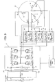
- Fig. 9 is a diagram schematically showing a configuration of a motor driving device according to a second embodiment of the present invention (in the case of the star connection).
- Fig. 10 is a diagram schematically showing the configuration of the motor driving device according to the second embodiment (in the case of the delta connection).
- each component identical or corresponding to a component shown in Fig. 1 is assigned the same reference character as in Fig. 1 .
- each component identical or corresponding to a component shown in Fig. 2 is assigned the same reference character as in Fig. 1 .
- the motor driving device according to the second embodiment differs from the motor driving device according to the first embodiment in the configuration of a connection switching unit 4 and a connection switching signal outputted from a control unit 7. Except these features, the motor driving device according to the second embodiment is the same as the motor driving device according to the first embodiment. Thus, the description of the second embodiment will be given mainly of the difference from the first embodiment.
- the motor driving device is a device that drives a motor 2 including stator windings of three phases.
- the motor driving device includes the inverter 1, the connection switching unit 4 that switches the connection condition of the open winding U, the open winding V and the open winding W to either of the first connection condition and the second connection condition different from the first connection condition, and the control unit 7 that controls the inverter 1 and the connection switching unit 4.
- the first connection condition is the condition of the star connection in which the neutral points are connected together by the connection switching unit 4
- the second connection condition is the condition of the delta connection.
- the connection switching unit 4 includes mechanical switches (e.g., open/close switches shown in Figs. 11(A) and 11(B) and Figs. 12(A) and 12(B) which will be explained later), namely, a relay (first relay) 41, a relay (second relay) 42, a relay (third relay) 43, a relay (fourth relay) 44, a relay (fifth relay) 45 and a relay (sixth relay) 46.
- a relay (first relay) 41 e.g., open/close switches shown in Figs. 11(A) and 11(B) and Figs. 12(A) and 12(B) which will be explained later
- a relay (first relay) 41 e.g., a relay (second relay) 42, a relay (third relay) 43, a relay (fourth relay) 44, a relay (fifth relay) 45 and a relay (sixth relay) 46.
- the relay 41 includes a first terminal 41a connected to an output terminal of the inverter 1, a second terminal 41b connected to the winding terminal 2u_2 of the open winding U, and a switch movable part 41e capable of connecting the first terminal 41a and the second terminal 41b together.
- the relay 42 includes a third terminal 42a, a fourth terminal 42b connected to the winding terminal 2u_2 of the open winding U, and a switch movable part 42e capable of connecting the third terminal 42a and the fourth terminal 42b together.
- the relay 43 includes a fifth terminal 43a connected to an output terminal of the inverter 1, a sixth terminal 43b connected to the winding terminal 2v_2 of the open winding V, and a switch movable part 43e capable of connecting the fifth terminal 43a and the sixth terminal 43b together.
- the relay 44 includes a seventh terminal 44a connected to the third terminal 42a, an eighth terminal 44b connected to the winding terminal 2v_2 of the open winding V, and a switch movable part 44e capable of connecting the seventh terminal 44a and the eighth terminal 44b together.
- the relay 45 includes a ninth terminal 45a connected to an output terminal of the inverter 1, a tenth terminal 45b connected to the winding terminal 2w_2 of the open winding W, and a switch movable part 45e capable of connecting the ninth terminal 45a and the tenth terminal 45b together.
- the relay 46 includes an eleventh terminal 46a connected to the third terminal 42a and the seventh terminal 44a, a twelfth terminal 46b connected to the winding terminal 2w_2 of the open winding W, and a switch movable part 46e capable of connecting the eleventh terminal 46a and the twelfth terminal 46b together.
- the connection switching unit 4 is capable of switching the connection condition of the stator windings to the star connection ( Fig. 3(A) ) that is the first connection condition by setting the first terminal 41a and the second terminal 41b in the open state, setting the fifth terminal 43a and the sixth terminal 43b in the open state, setting the ninth terminal 45a and the tenth terminal 45b in the open state, setting the third terminal 42a and the fourth terminal 42b in the closed state with the switch movable part 42e, setting the seventh terminal 44a and the eighth terminal 44b in the closed state with the switch movable part 44e, and setting the eleventh terminal 46a and the twelfth terminal 46b in the closed state with the switch movable part 46e.
- connection switching unit 4 is capable of switching the connection condition of the stator windings to the delta connection ( Fig. 3(B) ) that is the second connection condition by setting the first terminal 41a and the second terminal 41b in the closed state with the switch movable part 41e, setting the fifth terminal 43a and the sixth terminal 43b in the closed state with the switch movable part 43e, setting the ninth terminal 45a and the tenth terminal 45b in the closed state with the switch movable part 45e, setting the third terminal 42a and the fourth terminal 42b in the open state, setting the seventh terminal 44a and the eighth terminal 44b in the open state, and setting the eleventh terminal 46a and the twelfth terminal 46b in the open state.
- relays 41 to 46 are shown in Fig. 9 and Fig. 10 as components independent of each other, the relays 41 to 46 may be implemented as any type of relay that concurrently operates the three switch movable parts 41e, 43e and 45e and concurrently operates the three switch movable parts 42e, 44e and 46e, and the number of relays can be different from six.
- Figs. 11(A) and 11(B) are diagrams showing the relays 41 to 46 of the connection switching unit 4 in the motor driving device shown in Fig. 9 .
- Figs. 12(A) and 12(B) are diagrams showing the relays 41 to 46 of the connection switching unit 4 in the motor driving device shown in Fig. 10 .
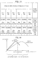
- Fig. 13 is a diagram showing an example of open states and closed states between terminals in the relays 41 to 46 shown in Figs. 11(A) and 11(B) and Figs. 12(A) and 12(B) in a tabular form.
- the relays 41, 43 and 45 have the same configuration as each other, and excitation switches 61b, 63b and 65b are operated in the same way and the switch movable parts 41e, 43e and 45e of the relays 41, 43 and 45 are operated in the same way according to the connection switching signal outputted from the control unit 7.
- the relays 42, 44 and 46 have the same configuration as each other, and excitation switches 62b, 64b and 66b are operated in the same way and the switch movable parts 42e, 44e and 46 of the relays 42, 44 and 46 are operated in the same way according to the connection switching signal outputted from the control unit 7.
- the relay 41 is capable of setting the first terminal 41a connected to an output terminal of the inverter 1 and the second terminal 41b connected to the winding terminal 2u_2 of the open winding U in the open state (disconnected state) when an excitation coil 61a is in the non-excitation state, or in the closed state (connected state) with the switch movable part 41e when the excitation coil 61a is in the excitation state.
- the relay 42 is capable of setting the third terminal 42a connected to an output terminal of the inverter 1 and the fourth terminal 42b connected to the winding terminal 2u_2 of the open winding U in the closed state (connected state) with the switch movable part 41e when an excitation coil 62a is in the non-excitation state, or in the open state (disconnected state) when the excitation coil 62a is in the excitation state.
- the relay 43 is capable of setting the fifth terminal 43a connected to an output terminal of the inverter 1 and the sixth terminal 43b connected to the winding terminal 2v_2 of the open winding V in the open state (disconnected state) when an excitation coil 63a is in the non-excitation state, or in the closed state (connected state) with the switch movable part 43e when the excitation coil 63a is in the excitation state.
- the relay 44 is capable of setting the seventh terminal 44a connected to an output terminal of the inverter 1 and the eighth terminal 44b connected to the winding terminal 2v_2 of the open winding V in the closed state (connected state) with the switch movable part 44e when an excitation coil 64a is in the non-excitation state, or in the open state (disconnected state) when the excitation coil 64a is in the excitation state.
- the relay 45 is capable of setting the ninth terminal 45a connected to an output terminal of the inverter 1 and the tenth terminal 45b connected to the winding terminal 2w_2 of the open winding W in the open state (disconnected state) when an excitation coil 65a is in the non-excitation state, or in the closed state (connected state) with the switch movable part 45e when the excitation coil 65a is in the excitation state.
- the relay 46 is capable of setting the eleventh terminal 46a connected to an output terminal of the inverter 1 and the twelfth terminal 46b connected to the winding terminal 2w_2 of the open winding W in the closed state (connected state) with the switch movable part 46e when an excitation coil 66a is in the non-excitation state, or in the open state (disconnected state) when the excitation coil 66a is in the excitation state.
- the connection switching unit 4 is capable of switching the connection condition of the stator windings to the star connection that is the first connection condition by setting the third terminal 42a and the fourth terminal 42b in the closed state (connecting the third terminal 42a and the fourth terminal 42b together) with the switch movable part 42e, setting the seventh terminal 44a and the eighth terminal 44b in the closed state (connecting the seventh terminal 44a and the eighth terminal 44b together) with the switch movable part 44e, and setting the eleventh terminal 46a and the twelfth terminal 46b in the closed state (connecting the eleventh terminal 46a and the twelfth terminal 46b together) with the switch movable part 46e in the non-excitation state of the excitation coils 61a, 62a, 63a, 64a, 65a and 66a with the excitation switches 61b, 62b, 63b, 64b and 65b open (off).
- current supplied from the inverter 1 flows between the third terminal 42a and the fourth terminal 42b through the switch movable part 42e connecting the third terminal 42a and the fourth terminal 42b together.
- current supplied from the inverter 1 flows between the seventh terminal 44a and the eighth terminal 44b through the switch movable part 44e connecting the seventh terminal 44a and the eighth terminal 44b together.
- current supplied from the inverter 1 flows between the eleventh terminal 46a and the twelfth terminal 46b through the switch movable part 46e connecting the eleventh terminal 46a and the twelfth terminal 46b together.
- the connection switching unit 4 is capable of switching the connection condition of the stator windings to the delta connection that is the second connection condition by setting the first terminal 41a and the second terminal 41b in the closed state (connecting the first terminal 41a and the second terminal 41b together) with the switch movable part 41e, setting the fifth terminal 43a and the sixth terminal 43b in the closed state (connecting the fifth terminal 43a and the sixth terminal 43b together) with the switch movable part 43e, and setting the ninth terminal 45a and the tenth terminal 45b in the closed state (connecting the ninth terminal 45a and the tenth terminal 45b together) with the switch movable part 45e in the excitation state of the excitation coils 61a, 62a, 63a, 64a, 65a and 66a with the excitation switches 61b, 62b, 63b, 64b and 65b closed (on) .
- the operation of the motor 2 is stopped (in a case of an air conditioner, the operation of the compressor driven by the motor is stopped), for example, for switching the connection condition and the connection condition switching operation is performed in the stoppage period.
- connection condition of the stator windings can be switched appropriately by switching the states of the switch movable parts 41e, 42e, 43e, 44e, 45e and 46e of the relays 41 to 46 as the mechanical switches included in the connection switching unit 4 through the excitation or non-excitation of the excitation coils 61a, 62a, 63a, 64a, 65a and 66a. Accordingly, the motor 2 can be driven in high speed rotation with the delta connection, and the motor 2 can be driven with high efficiency in low speed rotation with the star connection.
- Fig. 14 is a graph showing the relationship between the revolution speed of the motor 2 and the efficiency of the motor 2 in a case where the connection condition is the star connection and the delta connection.
- the horizontal axis of Fig. 14 represents the revolution speed of the motor 2 and the vertical axis of Fig. 14 represents the efficiency of the motor 2 (ratio of mechanical output power to input electric power).
- the efficiency of the motor 2 in the case where the connection condition is the star connection is excellent in a low speed (low load) region in which the revolution speed of the motor 2 is low, but drops in a high speed (overload) region in which the revolution speed of the motor 2 is high.
- connection condition is the delta connection
- the star connection excels in the efficiency in the low speed (low load) region
- the delta connection excels in the efficiency in the high speed (overload) region. Accordingly, it is desirable to make the switching to a connection condition of higher efficiency at the switching point shown in Fig. 14 .
- the excitation coils 61a, 62a, 63a, 64a, 65a and 66a are set in the non-excitation state as shown in Figs. 11(A) and 11(B) in the star connection achieving high efficiency in low speed rotation.
- the motor driving device according to the second embodiment is used for driving a motor for a compressor of an air conditioner, the electric power consumption can be reduced since the excitation of the excitation coils 61a, 62a, 63a, 64a, 65a and 66a is unnecessary in low speed rotation whose operating time is supposed to be long.
- the number of lines connected to one relay is two, and thus handling (attaching process) of lines in a circuit board having a limited area is easier compared to the case of the first embodiment in which the number of lines connected to one relay is three, and downsizing of the circuit board is possible.
- FIG. 14 is a block diagram showing a configuration of an air conditioner 105 according to a third embodiment of the present invention.
- the air conditioner 105 includes an indoor unit 105A that is installed in a room (in a cooling/heating object space) and an outdoor unit 105B that is installed outdoors.
- the indoor unit 105A and the outdoor unit 105B are connected together by connection piping 140 in which a refrigerant flows.
- the outdoor unit 105B includes a compressor 141 that compresses the refrigerant and discharges the compressed refrigerant, a four-way valve (refrigerant channel selector valve) 142 that switches the flow direction of the refrigerant, an outdoor heat exchanger 143 that performs heat exchange between outside air and the refrigerant, and an expansion valve (decompression device) 144 that decompresses the high-pressure refrigerant into low pressure.
- the compressor 141 is formed with a rotary compressor, for example.
- the indoor unit 105A includes an indoor heat exchanger 145 that performs heat exchange between indoor air and the refrigerant.
- the compressor 141, the four-way valve 142, the outdoor heat exchanger 143, the expansion valve 144 and the indoor heat exchanger 145 are connected together by the piping 140 to form a refrigerant circuit. With these components, a compression refrigeration cycle (compression heat pump cycle) circulating the refrigerant with the compressor 141 is formed.
- compression refrigeration cycle compression heat pump cycle
- an indoor control device 150a is arranged in the indoor unit 105A and an outdoor control device 150b is arranged in the outdoor unit 105B.
- Each of the indoor control device 150a and the outdoor control device 150b includes a control board on which various circuits for controlling the air conditioner 105 have been formed.
- the indoor control device 150a and the outdoor control device 150b are connected to each other by a communication cable 150c.
- an outdoor blower fan 146 as a blower is arranged to face the outdoor heat exchanger 143.
- the outdoor blower fan 146 rotates and thereby generates an air flow passing through the outdoor heat exchanger 143.
- the outdoor blower fan 146 is formed with a propeller fan, for example.
- the outdoor heat exchanger 143 is arranged in the air blow direction (direction of the air flow) of the outdoor blower fan 146.
- the four-way valve 142 is controlled by the outdoor control device 150b and switches the direction in which the refrigerant flows.
- the outdoor control device 150b switches the direction in which the refrigerant flows.
- the gas refrigerant discharged from the compressor 141 is sent to the outdoor heat exchanger 143.
- the four-way valve 142 is at the position indicated by the broken line in Fig. 15 , the gas refrigerant discharged from the compressor 141 is sent to the indoor heat exchanger 145.
- the expansion valve 144 is controlled by the outdoor control device 150b and decompresses the high-pressure refrigerant into low pressure by changing its opening degree.
- an indoor blower fan 147 as a blower is arranged to face the indoor heat exchanger 145.
- the indoor blower fan 147 rotates and thereby generates an air flow passing through the indoor heat exchanger 145.
- the indoor blower fan 147 is formed with a cross flow fan, for example.
- the indoor blower fan 147 is arranged on the downstream side of the indoor heat exchanger 145 in its air blow direction.
- the indoor unit 105A is provided with an indoor temperature sensor 154 as a temperature sensor that measures an indoor temperature Ta as an air temperature in the room (a temperature of the cooling/heating object) and sends temperature information (information signal) obtained by the measurement to the indoor control device 150a.
- the indoor temperature sensor 154 may be formed with a temperature sensor used for standard air conditioners, or it is also possible to use a radiation temperature sensor that detects a surface temperature of a wall, floor or the like in the room.
- the indoor unit 105A is further provided with a signal reception unit 156 that receives a command signal transmitted from a user operation unit operated by the user such as a remote control 155.
- a remote control 155 With the remote control 155, the user makes operation inputs (operation start and stoppage) or issues commands in regard to the operation (a set temperature, a wind speed, etc.) to the air conditioner 105.
- the compressor 141 is driven by the motor 2 described in the first or second embodiment.
- the motor 2 is generally formed integrally with a compression mechanism of the compressor 141.
- the compressor 141 is configured to be able to vary the operating revolution speed in a range of 20 rps to 120 rps in normal operation. With the increase in the revolution speed of the compressor 141, refrigerant circulation volume of the refrigerant circuit increases.
- the revolution speed of the compressor 141 is controlled by the outdoor control device 150b based on a temperature difference ⁇ T between the present indoor temperature Ta obtained by the indoor temperature sensor 154 and the set temperature Ts set by the user through the remote control 155. With the increase in the temperature difference ⁇ T, the compressor 141 rotates at higher speed and increases the circulation volume of the refrigerant.
- the rotation of the indoor blower fan 147 is controlled by the indoor control device 150a.
- the revolution speed of the indoor blower fan 147 can be switched in multiple steps (e.g., three steps of "high", “middle” and “low") .
- the revolution speed of the indoor blower fan 147 is switched based on the temperature difference ⁇ T between the measured indoor temperature Ta and the set temperature Ts.
- the rotation of the outdoor blower fan 146 is controlled by the outdoor control device 150b.
- the revolution speed of the outdoor blower fan 146 can be switched in multiple steps. For example, the revolution speed of the outdoor blower fan 146 is switched based on the temperature difference ⁇ T between the measured indoor temperature Ta and the set temperature Ts.
- the indoor unit 105A further includes a horizontal wind direction plate 148 and a vertical wind direction plate 149.
- the basic operation of the air conditioner 105 is as follows: In the cooling operation, the four-way valve 142 is switched to the position indicated by the solid line and the high-temperature and high-pressure gas refrigerant discharged from the compressor 141 flows into the outdoor heat exchanger 143.
- the outdoor heat exchanger 143 operates as a condenser.
- the air absorbs condensation heat of the refrigerant by means of heat exchange.
- the refrigerant is condensed into a high-pressure and low-temperature liquid refrigerant and then adiabatically expanded by the expansion valve 144 into a low-pressure and low-temperature two-phase refrigerant.
- the refrigerant that passed through the expansion valve 144 flows into the indoor heat exchanger 145 of the indoor unit 5A.
- the indoor heat exchanger 145 operates as an evaporator.
- the refrigerant absorbs evaporation heat and evaporates by means of heat exchange, and the air cooled down by the heat exchange is supplied to the inside of the room.
- the refrigerant evaporates into a low-temperature and low-pressure gas refrigerant and is then compressed again by the compressor 141 into the high-temperature and high-pressure refrigerant.
- the four-way valve 142 is switched to the position indicated by the dotted line and the high-temperature and high-pressure gas refrigerant discharged from the compressor 141 flows into the indoor heat exchanger 145.
- the indoor heat exchanger 145 operates as a condenser.
- the air absorbs condensation heat of the refrigerant by means of heat exchange.
- the refrigerant is condensed into a high-pressure and low-temperature liquid refrigerant and then adiabatically expanded by the expansion valve 144 into a low-pressure and low-temperature two-phase refrigerant.
- the refrigerant that passed through the expansion valve 144 flows into the outdoor heat exchanger 143 of the outdoor unit 105B.
- the outdoor heat exchanger 143 operates as an evaporator.
- the refrigerant absorbs evaporation heat and evaporates by means of heat exchange.
- the refrigerant evaporates into a low-temperature and low-pressure gas refrigerant and then compressed again by the compressor 141 into the high-temperature and high-pressure refrigerant.
- the indoor control device 150a and the outdoor control device 150b control the air conditioner 105 while exchanging information with each other via the communication cable 150c.
- the indoor control device 150a and the outdoor control device 150b will hereinafter be referred to collectively as a control device 150.
- the control device 150 corresponds to the control units 6 and 7 in the first and second embodiments.
- Fig. 16 is a block diagram showing a control system of the air conditioner 105.
- the control device 150 is formed with a microcomputer, for example.
- An input circuit 151, an arithmetic circuit 152 and an output circuit 153 have been installed in the control device 150.
- the command signal received by the signal reception unit 156 from the remote control 155 is inputted.
- the command signal includes a signal for setting an operation input, an operation mode, the set temperature, an air flow rate or a wind direction, for example.
- the temperature information indicating the indoor temperature detected by the indoor temperature sensor 154 is also inputted to the input circuit 151.
- the input circuit 151 outputs these pieces of input information to the arithmetic circuit 152.
- the arithmetic circuit 152 includes a CPU (Central Processing Unit) 157 and a memory 158.
- the CPU 157 performs arithmetic processing and judgment processing.
- the memory 158 stores various types of set values and programs to be used for the control of the air conditioner 105.
- the arithmetic circuit 152 performs computation and judgment based on the information inputted from the input circuit 151 and outputs the result to the output circuit 153.
- the output circuit 153 outputs control signals to the compressor 141, a connection switching unit 160, the converter 102, the inverter 1, the compressor 141, the four-way valve 142, the expansion valve 144, the outdoor blower fan 146, the indoor blower fan 147, the horizontal wind direction plate 148 and the vertical wind direction plate 149 based on the information inputted from the arithmetic circuit 152.
- the connection switching unit 160 is the connection switching unit 3 in the first embodiment or the connection switching unit 4 in the second embodiment.
- the control device 150 controls various types of devices in the indoor unit 105A and the outdoor unit 105B.
- each of the indoor control device 150a and the outdoor control device 150b is formed with a microcomputer.
- the arithmetic circuit 152 analyzes the command signal inputted from the remote control 155 via the input circuit 151 and figures out, for example, the operation mode and the temperature difference ⁇ T between the set temperature Ts and the indoor temperature Ta based on the result of the analysis.
- the operation mode is the cooling operation
- the basic operation of the air conditioner 105 is as described below.
- the control device 150 starts up in the delta connection that is the connection at the end of the previous operation.
- the control device 150 drives fan motors of the indoor blower fan 147 and the outdoor blower fan 146 as a startup process of the air conditioner 105.
- control device 150 outputs a voltage switching signal to the converter 102 supplying the DC voltage (bus voltage) to the inverter 1 and thereby raises the bus voltage of the converter 102 to a bus voltage corresponding to the delta connection (e.g., 390 V). Further, the control device 150 starts up the motor 2.
- the control device 150 performs the driving of the motor 2 in the delta connection. Specifically, the control device 150 controls the output voltage of the inverter 1 and thereby controls the revolution speed of the motor 2. Further, the control device 150 acquires the temperature difference ⁇ T between the indoor temperature detected by the indoor temperature sensor 154 and the set temperature set through the remote control 155 and raises the revolution speed depending on the temperature difference ⁇ T up to an allowable maximum revolution speed at the maximum (130 rps in this example). By this operation, the refrigerant circulation volume of the compressor 141 is increased, the cooling capacity is raised in the case of the cooling operation, and the heating capacity is raised in the case of the heating operation.
- the control device 150 decreases the revolution speed of the motor 2 depending on the temperature difference ⁇ T.
- the control device 150 operates the motor 2 at an allowable minimum revolution speed (20 rps in this example).
- the control device 150 stops the rotation of the motor 2 to avoid excessive cooling (or excessive heating). Accordingly, the compressor 141 shifts to the stopped state. Thereafter, when the temperature difference ⁇ T is greater than 0 again, the control device 150 restarts the rotation of the motor 2.
- control device 150 judges whether the switching of the stator windings from the delta connection to the star connection is necessary or not. Specifically, the control device 150 judges whether or not the connection condition of the stator windings is the delta connection and the aforementioned temperature difference ⁇ T is less than or equal to a threshold value ⁇ Tr (step S106).
- the threshold value ⁇ Tr is a temperature difference corresponding to an air conditioning load that is low to the extent that the switching to the star connection is possible.
- the switching from the delta connection to the star connection is made depending on the result of the comparison. If the connection condition of the stator windings is the delta connection and the temperature difference ⁇ T is less than or equal to the threshold value ⁇ Tr, the control device 150 outputs a stop signal to the inverter 1 and thereby stops the rotation of the motor 2. Thereafter, the control device 150 outputs a connection switching signal to the connection switching unit 160 and thereby switches the connection condition of the stator windings from the delta connection to the star connection. Subsequently, the control device 150 outputs a voltage switching signal to the converter 102, thereby lowers the bus voltage of the converter 102 to a voltage corresponding to the star connection (e.g., 280 V), and restarts the rotation of the motor 2.
- a voltage switching signal to the converter 102
- the control device 150 stops the rotation of the motor 2. Thereafter, the control device 150 outputs a connection switching signal to the connection switching unit 160 and thereby switches the connection condition of the stator windings from the star connection to the delta connection. Subsequently, the control device 150 outputs a voltage switching signal to the converter 102, thereby raises the bus voltage of the converter 102 to the voltage corresponding to the delta connection (e.g., 390 V), and restarts the rotation of the motor 2.
- the control device 150 outputs a voltage switching signal to the converter 102, thereby raises the bus voltage of the converter 102 to the voltage corresponding to the delta connection (e.g., 390 V), and restarts the rotation of the motor 2.
- the motor 2 can be driven to higher revolution speed compared with the star connection and that makes it possible to deal with higher loads. Accordingly, the temperature difference ⁇ T between the indoor temperature and the set temperature can be converged in a short time.
- the control device 150 stops the rotation of the motor 2 when an operation stop signal is received. Thereafter, the control device 150 switches the connection condition of the stator windings from the star connection to the delta connection. Incidentally, when the connection condition of the stator windings is already the delta connection, the connection condition is maintained.
- control device 150 performs a stoppage process of the air conditioner 105. Specifically, the control device 150 stops the fan motors of the indoor blower fan 47 and the outdoor blower fan 146. Thereafter, the CPU 57 of the control device 150 stops and the operation of the air conditioner 105 ends.
- the motor 2 is operated in the star connection of high efficiency when the temperature difference ⁇ T between the indoor temperature and the set temperature is relatively small (namely, less than or equal to the threshold value ⁇ Tr).
- the motor 2 is operated in the delta connection capable of dealing with higher loads. Accordingly, operating efficiency of the air conditioner 105 can be increased.
- the revolution speed of the motor 2 when switching from the star connection to the delta connection, it is also possible to detect the revolution speed of the motor 2 before stopping the rotation of the motor 2 and make a judgment on whether or not the detected revolution speed is higher than or equal to a threshold value.
- a threshold value for the revolution speed of the motor 2 60 rps as the midpoint between a revolution speed 35 rps corresponding to a heating intermediate condition and a revolution speed 85 rps corresponding to a heating rated condition is used, for example. If the revolution speed of the motor 2 is higher than or equal to the threshold value, the rotation of the motor 2 is stopped, the switching to the delta connection is made, and the bus voltage of the converter 102 is raised.
- Fig. 17 is a timing chart showing an example of the operation of the air conditioner 105.
- Fig. 17 shows operational status of the air conditioner 105 and drive status of the outdoor blower fan 146 and the motor 2 (compressor 141).
- the outdoor blower fan 146 is shown as an example of a component of the air conditioner 105 other than the motor 2.
- the CPU 157 In response to an operation startup signal (ON command) received by the signal reception unit 156 from the remote control 155, the CPU 157 starts up and the air conditioner 105 shifts to a startup state (ON state).
- a startup state ON state
- the fan motor of the outdoor blower fan 146 starts rotating after the elapse of a time t0.
- the time t0 is a delay time due to the communication between the indoor unit 105A and the outdoor unit 105B.
- the time t1 is a waiting time until the rotation of the fan motor of the outdoor blower fan 146 stabilizes.
- the switching from the delta connection to the star connection is made, the switching from the star connection to the delta connection is also made, and the operation stop signal (OFF command) is received from the remote control 155.
- the time t2 necessary for the connection switching is set at a time necessary for the refrigerant pressure in the refrigeration cycle to become approximately uniform.
- the time t3 is a waiting time necessary for sufficiently lowering the temperature of the refrigeration cycle.
- the CPU 157 stops and the air conditioner 105 shifts to an operation stop state (OFF state).
- the time t4 is a previously set waiting time.
- connection switching unit 3 or 4 of the motor driving device in the first or second embodiment can be used as the connection switching unit 160. Therefore, the connection condition of the stator windings can be switched appropriately by switching the states of the switch movable parts 31e to 33e or 41e to 46e of the relays 31 to 33 or 41 to 46 as the mechanical switches included in the connection switching unit 3 or 4 through the excitation or non-excitation of the excitation coils 51a to 53a or 61a to 66a. Accordingly, the motor 2 can be driven in high speed rotation with the delta connection, and the motor 2 can be driven with high efficiency in low speed rotation with the star connection.
- the electric power consumption can be reduced since the excitation (energization) of the excitation coils 51a to 53a or 61a to 66a is unnecessary in low speed rotation whose operating time is supposed to be long.
- the air conditioning operation and the conditions for the switching of the connection condition described above are just an example; the conditions for the switching between the star connection and the delta connection may be determined based on various conditions such as the motor revolution speed, the motor current and a modulation factor or a combination of various conditions, for example.
Landscapes
- Engineering & Computer Science (AREA)
- Mechanical Engineering (AREA)
- General Engineering & Computer Science (AREA)
- Power Engineering (AREA)
- Physics & Mathematics (AREA)
- Thermal Sciences (AREA)
- Chemical & Material Sciences (AREA)
- Combustion & Propulsion (AREA)
- Fluid Mechanics (AREA)
- Control Of Ac Motors In General (AREA)
- Air Conditioning Control Device (AREA)
Abstract
Description
- The present invention relates to a motor driving device for driving a motor and to an air conditioner including a motor driving device for driving a motor for a compressor.
- Cooling capacity and heating capacity of an air conditioner (A/C) can be adjusted by changing rotational speed of a motor for a compressor. For example, at startup of the air conditioner, a quick cooling operation or a quick heating operation is performed by making the motor rotate at high speed, and after the room temperature has reached a requested temperature, an energy-saving operation is performed by making the motor rotate at low speed. Since the time of the energy-saving operation is generally long, using a motor having high efficiency in low speed rotation is desirable for reducing the annual electric energy consumption. Further, to raise the maximum capacity of cooling and heating, it is desirable to use a motor capable of high speed rotation.
- As the motor for a compressor, permanent magnet motors including a permanent magnet in the rotor are widely used in order to increase the efficiency. As a device for driving a motor, motor driving devices including an inverter have become widespread. In a permanent magnet motor, increasing the number of turns of a stator winding enables operation with a smaller amount of current, decreases inverter loss due to the current, and enables operation with higher efficiency. However, increasing the number of turns of the stator winding leads to a rise in inductive voltage, and thus motor voltage ruled by the inductive voltage reaches the maximum output voltage of the inverter at a low rotational speed and operation at higher rotational speeds is impossible.
- In contrast, decreasing the number of turns of the stator winding lowers the inductive voltage, and thus the motor voltage ruled by the inductive voltage hardly reaches the maximum output voltage of the inverter and the motor can be operated in high speed rotation. However, decreasing the number of turns of the stator winding increases the current flowing into the stator winding, and thus the inverter loss due to the current increases and operation with high efficiency becomes impossible.
- As above, permanent magnet motors with high efficiency in low speed rotation cannot be operated in high speed rotation, and permanent magnet motors that can be operated in high speed rotation are low in the efficiency in low speed rotation. To eliminate this problem, there has been proposed a motor driving device including a connection switching unit that switches stator windings of a motor receiving drive voltage supplied from an inverter between star connection and delta connection (see
Patent Reference 1, for example). - Patent Reference 1: Japanese Patent Application Publication No.
2006-246674 claim 1, paragraphs 0016 to 0020 and 0047 to 0048,Fig. 1 ,Fig. 2 andFig. 7 ) - However, in the motor driving device described in the
Patent Reference 1, electric power consumption necessary for maintaining the status of mechanical switches of the connection switching unit is not taken into consideration and there are cases where efficiency improvement is insufficient especially in low speed rotation whose operating time is long. - The object of the present invention is to provide a motor driving device capable of driving a motor in high speed rotation and driving the motor with high efficiency in low speed rotation and an air conditioner capable of achieving both of high cooling/heating capacity and operation with great energy saving effect.
- A motor driving device according to an aspect of the present invention is a motor driving device for driving a motor including stator windings, including: a connection switching unit that includes a mechanical switch connected to the stator windings and an excitation coil opening or closing the mechanical switch by being energized or non-energized with excitation current and switches connection condition of the stator windings to either of first connection condition and second connection condition different from the first connection condition by opening or closing the mechanical switch; and an inverter that supplies AC drive voltages to the stator windings.
- An air conditioner according to an aspect of the present invention is an air conditioner including a motor including stator windings, a compressor driven by the motor, and a motor driving device that drives the motor. The motor driving device includes: a connection switching unit that includes a mechanical switch connected to the stator windings and an excitation coil opening or closing the mechanical switch by being energized or non-energized with excitation current and switches connection condition of the stator windings to either of first connection condition and second connection condition different from the first connection condition by opening or closing the mechanical switch; and an inverter that supplies AC drive voltages to the stator windings.
- With the motor driving device according to the present invention, the connection condition of the stator windings can be switched appropriately by the opening or closing of the mechanical switch, and thus the motor can be driven in high speed rotation, and the motor can be driven with high efficiency in low speed rotation.
- Further, with the motor driving device according to the present invention, the electric power consumption can be reduced by appropriately controlling the energization of the excitation coil opening or closing the mechanical switch, by which energy saving performance can be improved.
- Furthermore, the air conditioner according to the present invention includes the motor driving device described above, and thus it is possible to achieve both of the high cooling/heating capacity due to high speed rotation of the motor for the compressor and the energy-saving operation of the motor for the compressor.
-
-
Fig. 1 is a diagram schematically showing a configuration of a motor driving device according to a first embodiment of the present invention (in a case of star connection). -
Fig. 2 is a diagram schematically showing the configuration of the motor driving device according to the first embodiment (in a case of delta connection). -
Figs. 3(A) and 3(B) are diagrams showing the star connection and the delta connection. -
Fig. 4 is a cross-sectional view schematically showing internal structure of a motor shown inFig. 1 andFig. 2 . -
Figs. 5(A) to 5(C) are diagrams showing U-phase windings connected in series, V-phase windings connected in series, and W-phase windings connected in series. -
Figs. 6(A) to 6(C) are diagrams showing U-phase windings connected in parallel, V-phase windings connected in parallel, and W-phase windings connected in parallel. -
Figs. 7(A) and 7(B) are diagrams showing relays of a connection switching unit in the motor driving device shown inFig. 1 andFig. 2 . -
Fig. 8 is a diagram showing an example of open/closed states of the relays in the connection switching unit shown inFigs. 7(A) and 7(B) in a tabular form. -
Fig. 9 is a diagram schematically showing a configuration of a motor driving device according to a second embodiment of the present invention (in the case of the star connection). -
Fig. 10 is a diagram schematically showing the configuration of the motor driving device according to the second embodiment (in the case of the delta connection). -
Figs. 11(A) and 11(B) are diagrams showing relays of a connection switching unit in the motor driving device shown inFig. 9 . -
Figs. 12(A) and 12(B) are diagrams showing the relays of the connection switching unit in the motor driving device shown inFig. 10 . -
Fig. 13 is a diagram showing an example of open/closed states of the relays in the connection switching unit shown inFig. 9 andFig. 10 in a tabular form. -
Fig. 14 is a graph showing the relationship between revolution speed of the motor and efficiency of the motor in a case where connection condition is the star connection and the delta connection. -
Fig. 15 is a block diagram showing a configuration of an air conditioner according to a third embodiment of the present invention. -
Fig. 16 is a block diagram showing a control system of the air conditioner according to the third embodiment. -
Fig. 17 is a timing chart showing an example of operation of the air conditioner according to the third embodiment. -
Fig. 1 is a diagram schematically showing a configuration of a motor driving device according to a first embodiment of the present invention (in a case of star connection).Fig. 2 is a diagram schematically showing the configuration of the motor driving device according to the first embodiment (in a case of delta connection).Figs. 3(A) and 3(B) are diagrams showing the star connection (Y connection) and the delta connection (Δ connection). - As shown in
Fig. 1 andFig. 2 , the motor driving device according to the first embodiment is a device that is connected to aconverter 102 converting AC voltage supplied from an AC power supply into DC voltage and drives amotor 2 including stator windings of three phases, namely, a U-phase, a V-phase and a W-phase. - The motor driving device according to the first embodiment includes an
inverter 1 that converts the DC voltage into AC drive voltages to be supplied to an open winding (first open winding) U, an open winding (second open winding) V and an open winding (third open winding) W that are the stator windings, aconnection switching unit 3 that switches connection condition of the open winding U, the open winding V and the open winding W to either of first connection condition and second connection condition different from the first connection condition, and acontrol unit 6 that controls theinverter 1 and theconnection switching unit 3. Further, the motor driving device may also include theconverter 102. - In the first embodiment, the first connection condition is condition of the star connection (
Fig. 3(A) ) in which neutral points are connected together by theconnection switching unit 3, and the second connection condition is condition of the delta connection (Fig. 3(B) ). However, the number of phases of the stator windings of themotor 2 is not limited to three but can also be two or four or more. - The open winding U includes a winding terminal (first winding terminal) 2u_1 connected to a U-phase output terminal of the
inverter 1 and a winding terminal (second winding terminal) 2u_2 connected to theconnection switching unit 3. The open winding V includes a winding terminal (third winding terminal) 2v_1 connected to a V-phase output terminal of theinverter 1 and a winding terminal (fourth winding terminal) 2v_2 connected to theconnection switching unit 3. The open winding W includes a winding terminal (fifth winding terminal) 2w_1 connected to a W-phase output terminal of theinverter 1 and a winding terminal (sixth winding terminal) 2w_2 connected to theconnection switching unit 3. - As shown in
Fig. 1 andFig. 2 , theinverter 1 includes MOS transistors (MOSFETs: Metal-Oxide-Semiconductor Field-Effect Transistors) 11a and 12a as switches connected in series between electricpower supply lines MOS transistors power supply lines MOS transistors power supply lines capacitor 17 connected between the electricpower supply lines - The electric
power supply lines converter 102 converting the AC voltage into the DC voltage. The U-phase output terminal of theinverter 1 is connected to a node between theMOS transistors inverter 1 is connected to a node between theMOS transistors inverter 1 is connected to a node between theMOS transistors MOS transistor control unit 6, that is, a gate control signal for the MOS transistor. - The
inverter 1 further includesparasitic diodes MOS transistors inverter 1 is not limited to the configuration shown inFig. 1 andFig. 2 . - As shown in
Fig. 1 andFig. 2 , theconnection switching unit 3 includes mechanical switches (e.g., selection switches shown inFigs. 7(A) and 7(B) which will be explained later), namely, a relay (first relay) 31, a relay (second relay) 32 and a relay (third relay) 33. The number of relays of theconnection switching unit 3 is greater than or equal to the number of phases of the open windings of the stator windings. - The
relay 31 has a first terminal (contact point) 31a connected to the V-phase output terminal of theinverter 1, a second terminal (contact point) 31b connected to a fifth terminal (contact point) 32b of therelay 32 and an eighth terminal (contact point) 33b of therelay 33 which will be described later, and a third terminal 31c connected to the winding terminal 2u_2 of the open winding U and electrically connected to one of thefirst terminal 31a and thesecond terminal 31b via a switchmovable part 31e. - The
relay 32 has a fourth terminal (contact point) 32a connected to the W-phase output terminal of theinverter 1, the fifth terminal (contact point) 32b connected to the second terminal 31b of therelay 31 and the eighth terminal 33b of therelay 33, and a sixth terminal 32c connected to the winding terminal 2v_2 of the open winding V and electrically connected to one of thefourth terminal 32a and thefifth terminal 32b via a switchmovable part 32e. - The
relay 33 has a seventh terminal (contact point) 33a connected to the U-phase output terminal of theinverter 1, the eighth terminal (contact point) 33b connected to the second terminal 31b of therelay 31 and the fifth terminal 32b of therelay 32, and a ninth terminal 33c connected to the winding terminal 2w_2 of the open winding W and electrically connected to one of theseventh terminal 33a and theeighth terminal 33b via a switchmovable part 33e. - In the
connection switching unit 3, the closing (conduction, namely, connection) and the opening (non-conduction, namely, disconnection) between terminals of the relays as the mechanical switches are controlled according to a connection switching signal outputted from the control unit 6 (e.g., control signal for an excitation switch that switches between excitation and non-excitation of an excitation coil shown inFigs. 7(A) and 7(B) which will be explained later). - The connection switching signal is, for example, a control signal that commands ON or OFF of the excitation switch for switching between the excitation (energization) and the non-excitation (non-energization) of the excitation coil shown in
Figs. 7(A) and 7(B) which will be explained later. The connection switching signal is, for example, a control signal for the excitation switch that switches between the excitation and the non-excitation of the excitation coil shown inFigs. 7(A) and 7(B) which will be explained later. - The
connection switching unit 3 switches the connection condition of the stator windings of themotor 2 to the star connection (Fig. 3(A) ) that is the first connection condition in which the neutral points are connected together by theconnection switching unit 3, by connecting thesecond terminal 31b and the third terminal 31c together via the switchmovable part 31e in therelay 31, connecting thefifth terminal 32b and the sixth terminal 32c together via the switchmovable part 32e in therelay 32, and connecting theeighth terminal 33b and the ninth terminal 33c together via the switchmovable part 33e in therelay 33. - Further, the
connection switching unit 3 switches the connection condition to the delta connection (Fig. 3(B) ) as the second connection condition by connecting thefirst terminal 31a and the third terminal 31c together via the switchmovable part 31e in therelay 31, connecting thefourth terminal 32a and the sixth terminal 32c together via the switchmovable part 32e in therelay 32, and connecting theseventh terminal 33a and the ninth terminal 33c together via the switchmovable part 33e in therelay 33. - It is desirable from the viewpoint of reducing the electric power consumption that the
control unit 6 select the star connection by non-exciting the excitation coils of therelays 31 to 33 in an operation mode in which ratio of the loss in theconnection switching unit 3 to the total loss in the motor driving device is high, and select the delta connection by exciting the excitation coils of therelays 31 to 33 in an operation mode in which the ratio is low. - Incidentally, while the
relays Fig. 1 andFig. 2 as components independent of each other, therelays movable parts -
Fig. 4 is a cross-sectional view schematically showing the internal structure of themotor 2 shown inFig. 1 andFig. 2 . As shown inFig. 3 , themotor 2 is a permanent magnet motor in whichpermanent magnets 26 are embedded in arotor 25. Themotor 2 includes astator 21 and therotor 25 arranged in a space on a central side of thestator 21 and supported to be rotatable around a shaft. An air gap is secured between an outer circumferential surface of therotor 25 and an inner circumferential surface of thestator 21. The air gap between thestator 21 and therotor 25 is a clearance of approximately 0.3 mm to 1 mm. Specifically, therotor 25 is rotated by energizing the stator windings with electric current in sync with a command revolution speed by use of theinverter 1 and generating a rotating magnetic field. - Windings U1 to U3, windings V1 to V3, and windings W1 to W3 are wound around
tooth parts 22 of thestator 21 via insulating material by means of concentrated winding. The windings U1 to U3 correspond to the open winding U inFig. 1 , the windings V1 to V3 correspond to the open winding V inFig. 1 , and the windings W1 to W3 correspond to the open winding W inFig. 1 . - The
stator 21 shown inFig. 4 is formed of a plurality of split cores, and the split cores arranged in a ring-like shape (a state in which the split cores are closed) can be turned into the split cores arranged in a straight line (a state in which the split cores are open) by opening thetooth parts 22 adjacently arranged around arotation axis 23 and connecting adjacent split cores together. With this configuration, the winding process can be performed in a state in which the split cores are arranged in a straight line and thetooth parts 22 have wide spaces between each other, by which the winding process can be simplified and winding quality can be improved (e.g., occupancy ratio can be increased). - As the
permanent magnets 26 embedded in therotor 25, rare-earth magnets or ferrite magnets are employed, for example.Slits 27 are arranged in outer circumferential core parts of thepermanent magnets 26. Theslits 27 have a function of lessening the influence of armature reaction caused by the electric current of the stator windings and reducing the superimposition of harmonics on the magnetic flux distribution. Further, the core of thestator 21 and the core of therotor 25 are provided withair vents motor 2 while serving as refrigerant gas channels or oil return channels. - The
motor 2 shown inFig. 4 has structure of concentrated winding in which the ratio between the number of magnetic poles and the number of slots is 2 : 3. Themotor 2 includes the rotor having permanent magnets for six poles and thestator 21 having nine slots (nine tooth parts). Thus, themotor 2, being a six-pole motor having six permanent magnets, employs structure having windings on three tooth parts (three slots) per phase. In a case of a four-pole motor, the number of tooth parts (the number of slots) is six and it is desirable to employ structure having windings on two tooth parts per phase. In a case of an eight-pole motor, the number of tooth parts is twelve and it is desirable to employ structure having windings on four tooth parts per phase. When three-phase windings are used in the delta connection, there are cases where circulating current flows in the windings of themotor 2 and deteriorates the performance of themotor 2. The circulating current flows due to the third harmonic of inductive voltage in the winding of each phase, and in the case of the concentrated winding in which the ratio between the number of magnetic poles and the number of slots is 2 : 3, no third harmonic occurs in the inductive voltage due to phase relationship between the windings and the permanent magnets as long as there is no influence of magnetic saturation or the like. In the first embodiment, themotor 2 is configured with the concentrated winding in which the ratio between the number of magnetic poles and the number of slots is 2 : 3 in order to inhibit the circulating current in use of themotor 2 in delta connection. However, the number of magnetic poles, the number of slots, and the winding method (concentrated winding, distributed winding) may be properly selected depending on required motor size, characteristics (revolution speed, torque, etc.), voltage specifications, cross-sectional area of the slots, and so forth. Further, the structure of the motor to which the present invention is applicable is not limited to that shown inFig. 3 . -
Figs. 5(A) to 5(C) show an example of the windings shown inFig. 3 , namely, the windings U1, U2 and U3 connected in series, the windings V1, V2 and V3 connected in series, and the windings W1, W2 and W3 connected in series.Figs. 6(A) to 6(C) show another example of the windings shown inFig. 3 , namely, the windings U1, U2 and U3 connected in parallel, the windings V1, V2 and V3 connected in parallel, and the windings W1, W2 and W3 connected in parallel. -
Figs. 7(A) and 7(B) are diagrams showing therelays connection switching unit 3 in the motor driving device shown inFig. 1 andFig. 2 . Therelays relay 31 will be described in detail below and description of the configuration and operation of therelays - As shown in
Figs. 7(A) and 7(B) , an excitation unit including apower supply 50, anexcitation coil 51a and anexcitation switch 51b is provided in the vicinity of therelay 31. The excitation unit opens (is turned off) theexcitation switch 51b and thereby shifts to a non-excitation state in which no excitation current is fed to theexcitation coil 51a, or closes (is turned on) theexcitation switch 51b and thereby shifts to an excitation state in which excitation current flows from thepower supply 50 to theexcitation coil 51a and excitation occurs to theexcitation coil 51a. Theexcitation coil 51a is arranged at a position adjoining thefirst terminal 31a of therelay 31, and thesecond terminal 31b is arranged at a position farther than thefirst terminal 31a. - The
relay 31 includes the switchmovable part 31e in addition to thefirst terminal 31a connected to an output terminal of theinverter 1, thesecond terminal 31b, and the third terminal 31c connected to the winding terminal 2u_2 of the open winding U. One end (first end) of the switchmovable part 31e is connected to the third terminal 31c, while the other end (second end) of the switchmovable part 31e is electrically connected to one of thefirst terminal 31a and thesecond terminal 31b depending on the state of the excitation switch. - As shown in
Fig. 7(A) , in the non-excitation state in which theexcitation switch 51b is opened (set to off) and no excitation current is fed to theexcitation coil 51a, the other end of the switchmovable part 31e is connected to thesecond terminal 31b and therelay 31 electrically connects thesecond terminal 31b and the third terminal 31c together. - As shown in
Fig. 7(B) , in the excitation state in which theexcitation switch 51b is closed (set to on) and the excitation current is supplied from thepower supply 50 to theexcitation coil 51a, the other end of the switchmovable part 31e is attracted by the excitation occurring to theexcitation coil 51a and approaches from the second terminal 31b to thefirst terminal 31a, and therelay 31 electrically connects thefirst terminal 31a and the third terminal 31c together by use of the switchmovable part 31e connected to thefirst terminal 31a. - The
relay 32 includes thefourth terminal 32a connected to an output terminal of theinverter 1, thefifth terminal 32b connected to thesecond terminal 31b, and the sixth terminal 32c connected to the winding terminal 2v_2 of the open winding V and electrically connected to one of thefourth terminal 32a and thefifth terminal 32b by the switchmovable part 32e. - As shown in
Fig. 7(A) , in the non-excitation state in which theexcitation switch 52b is opened (set to off) and no excitation current is fed to theexcitation coil 52a, therelay 32 electrically connects thefifth terminal 32b and the sixth terminal 32c together by use of the switchmovable part 32e. As shown inFig. 7(B) , in the excitation state in which theexcitation switch 52b is closed (set to on) and the excitation current is supplied from thepower supply 50 to theexcitation coil 52a, therelay 32 electrically connects thefourth terminal 32a and the sixth terminal 32c together by use of the switchmovable part 32e. - The
relay 33 includes theseventh terminal 33a connected to theinverter 1, theeighth terminal 33b connected to thesecond terminal 31b and thefifth terminal 32b, and theninth terminal 33c connected to the winding terminal 2w_2 of the open winding W and electrically connected to one of theseventh terminal 33a and theeighth terminal 33b by the switchmovable part 33e. - As shown in
Fig. 7(A) , in the non-excitation state in which theexcitation switch 53b is opened (set to off) and no excitation current is fed to theexcitation coil 53a, therelay 33 electrically connects theeighth terminal 33b and the ninth terminal 33c together by use of the switchmovable part 33e. As shown inFig. 7(B) , in the excitation state in which theexcitation switch 53b is closed (set to on) and the excitation current is supplied from thepower supply 50 to theexcitation coil 53a, therelay 33 electrically connects theseventh terminal 33a and the ninth terminal 33c together by use of the switchmovable part 33e. -
Fig. 8 is a diagram showing an example of open states and closed states between terminals of the mechanical switches in therelays Figs. 7(A) and 7(B) in a tabular form. Therelays movable parts relays control unit 6. - As shown in
Fig. 1 ,Fig. 7(A) andFig. 8 , theconnection switching unit 3 is capable of switching the connection condition of the stator windings to the star connection that is the first connection condition by setting thesecond terminal 31b and the third terminal 31c in the closed state (connecting thesecond terminal 31b and the third terminal 31c together) with the switchmovable part 31e, setting thefifth terminal 32b and the sixth terminal 32c in the closed state (connecting thefifth terminal 32b and the sixth terminal 32c together) with the switchmovable part 32e, and setting theeighth terminal 33b and the ninth terminal 33c in the closed state (connecting theeighth terminal 33b and the ninth terminal 33c together) with the switchmovable part 33e in the non-excitation state in which the excitation switches 51b, 52b and 53b are opened (set to off) and no excitation current is fed to theexcitation coils - In this case, current supplied from the
inverter 1 flows between thesecond terminal 31b and the third terminal 31c through the switchmovable part 31e connecting thesecond terminal 31b and the third terminal 31c together. Similarly, current supplied from theinverter 1 flows between thefifth terminal 32b and the sixth terminal 32c through the switchmovable part 32e connecting thefifth terminal 32b and the sixth terminal 32c together. Similarly, current supplied from theinverter 1 flows between theeighth terminal 33b and the ninth terminal 33c through the switchmovable part 33e connecting theeighth terminal 33b and the ninth terminal 33c together. - As shown in
Fig. 2 ,Fig. 7(B) andFig. 8 , theconnection switching unit 3 is capable of switching the connection condition of the stator windings to the delta connection that is the second connection condition by setting thefirst terminal 31a and the third terminal 31c in the closed state (connecting thefirst terminal 31a and the third terminal 31c together) with the switchmovable part 31e, setting thefourth terminal 32a and the sixth terminal 32c in the closed state (connecting thefourth terminal 32a and the sixth terminal 32c together) with the switchmovable part 32e, and setting theseventh terminal 33a and the ninth terminal 33c in the closed state (connecting theseventh terminal 33a and the ninth terminal 33c together) with the switchmovable part 33e in the excitation state in which the excitation switches 51b, 52b and 53b are closed (set to on) and the excitation current is fed to theexcitation coils - In this case, current supplied from the
inverter 1 flows between thefirst terminal 31a and the third terminal 31c through the switchmovable part 31e connecting thefirst terminal 31a and the third terminal 31c together. Similarly, current supplied from theinverter 1 flows between thefourth terminal 32a and the sixth terminal 32c through the switchmovable part 32e connecting thefourth terminal 32a and the sixth terminal 32c together. Similarly, current supplied from theinverter 1 flows between theseventh terminal 33a and the ninth terminal 33c through the switchmovable part 33e connecting theseventh terminal 33a and the ninth terminal 33c together. - Since the switching time of the mechanical switches of the
connection switching unit 3 is normally some hundred milliseconds, the operation of themotor 2 is stopped (in a case of an air conditioner, the operation of the compressor driven by the motor is stopped) for switching the connection condition and the connection condition switching operation is performed in the stoppage period. Incidentally, switching timing of the connection condition will be explained in a third embodiment which will be described later. - As described above, with the motor driving device according to the first embodiment, the connection condition of the stator windings can be switched appropriately by switching the states of the switch
movable parts relays connection switching unit 3 through the excitation or non-excitation of theexcitation coils motor 2 can be driven in high speed rotation with the delta connection, and themotor 2 can be driven with high efficiency in low speed rotation with the star connection. - Further, with the motor driving device according to the first embodiment, the
excitation coils Fig. 7(A) in the star connection achieving high efficiency in low speed rotation. Thus, in a case where the motor driving device according to the first embodiment is used for driving a motor for a compressor of an air conditioner, electric power consumption can be reduced since the excitation of theexcitation coils -
Fig. 9 is a diagram schematically showing a configuration of a motor driving device according to a second embodiment of the present invention (in the case of the star connection).Fig. 10 is a diagram schematically showing the configuration of the motor driving device according to the second embodiment (in the case of the delta connection). InFig. 9 , each component identical or corresponding to a component shown inFig. 1 is assigned the same reference character as inFig. 1 . InFig. 10 , each component identical or corresponding to a component shown inFig. 2 is assigned the same reference character as inFig. 1 . - The motor driving device according to the second embodiment differs from the motor driving device according to the first embodiment in the configuration of a
connection switching unit 4 and a connection switching signal outputted from acontrol unit 7. Except these features, the motor driving device according to the second embodiment is the same as the motor driving device according to the first embodiment. Thus, the description of the second embodiment will be given mainly of the difference from the first embodiment. - As shown in
Fig. 9 andFig. 10 , the motor driving device according to the second embodiment is a device that drives amotor 2 including stator windings of three phases. The motor driving device according to the second embodiment includes theinverter 1, theconnection switching unit 4 that switches the connection condition of the open winding U, the open winding V and the open winding W to either of the first connection condition and the second connection condition different from the first connection condition, and thecontrol unit 7 that controls theinverter 1 and theconnection switching unit 4. In the second embodiment, the first connection condition is the condition of the star connection in which the neutral points are connected together by theconnection switching unit 4, and the second connection condition is the condition of the delta connection. - As shown in
Fig. 9 andFig. 10 , theconnection switching unit 4 includes mechanical switches (e.g., open/close switches shown inFigs. 11(A) and 11(B) and Figs. 12(A) and 12(B) which will be explained later), namely, a relay (first relay) 41, a relay (second relay) 42, a relay (third relay) 43, a relay (fourth relay) 44, a relay (fifth relay) 45 and a relay (sixth relay) 46. - The
relay 41 includes afirst terminal 41a connected to an output terminal of theinverter 1, asecond terminal 41b connected to the winding terminal 2u_2 of the open winding U, and a switchmovable part 41e capable of connecting thefirst terminal 41a and thesecond terminal 41b together. Therelay 42 includes athird terminal 42a, afourth terminal 42b connected to the winding terminal 2u_2 of the open winding U, and a switchmovable part 42e capable of connecting thethird terminal 42a and the fourth terminal 42b together. - The
relay 43 includes afifth terminal 43a connected to an output terminal of theinverter 1, asixth terminal 43b connected to the winding terminal 2v_2 of the open winding V, and a switchmovable part 43e capable of connecting thefifth terminal 43a and the sixth terminal 43b together. Therelay 44 includes aseventh terminal 44a connected to thethird terminal 42a, aneighth terminal 44b connected to the winding terminal 2v_2 of the open winding V, and a switchmovable part 44e capable of connecting theseventh terminal 44a and the eighth terminal 44b together. - The
relay 45 includes aninth terminal 45a connected to an output terminal of theinverter 1, atenth terminal 45b connected to the winding terminal 2w_2 of the open winding W, and a switchmovable part 45e capable of connecting theninth terminal 45a and the tenth terminal 45b together. Therelay 46 includes aneleventh terminal 46a connected to thethird terminal 42a and theseventh terminal 44a, atwelfth terminal 46b connected to the winding terminal 2w_2 of the open winding W, and a switchmovable part 46e capable of connecting theeleventh terminal 46a and the twelfth terminal 46b together. - As shown in
Fig. 9 , theconnection switching unit 4 is capable of switching the connection condition of the stator windings to the star connection (Fig. 3(A) ) that is the first connection condition by setting thefirst terminal 41a and thesecond terminal 41b in the open state, setting thefifth terminal 43a and the sixth terminal 43b in the open state, setting theninth terminal 45a and thetenth terminal 45b in the open state, setting thethird terminal 42a and thefourth terminal 42b in the closed state with the switchmovable part 42e, setting theseventh terminal 44a and theeighth terminal 44b in the closed state with the switchmovable part 44e, and setting theeleventh terminal 46a and thetwelfth terminal 46b in the closed state with the switchmovable part 46e. - Further, as shown in
Fig. 10 , theconnection switching unit 4 is capable of switching the connection condition of the stator windings to the delta connection (Fig. 3(B) ) that is the second connection condition by setting thefirst terminal 41a and thesecond terminal 41b in the closed state with the switchmovable part 41e, setting thefifth terminal 43a and the sixth terminal 43b in the closed state with the switchmovable part 43e, setting theninth terminal 45a and thetenth terminal 45b in the closed state with the switchmovable part 45e, setting thethird terminal 42a and thefourth terminal 42b in the open state, setting theseventh terminal 44a and theeighth terminal 44b in the open state, and setting theeleventh terminal 46a and thetwelfth terminal 46b in the open state. - Incidentally, while the six
relays 41 to 46 are shown inFig. 9 andFig. 10 as components independent of each other, therelays 41 to 46 may be implemented as any type of relay that concurrently operates the three switchmovable parts movable parts -
Figs. 11(A) and 11(B) are diagrams showing therelays 41 to 46 of theconnection switching unit 4 in the motor driving device shown inFig. 9 .Figs. 12(A) and 12(B) are diagrams showing therelays 41 to 46 of theconnection switching unit 4 in the motor driving device shown inFig. 10 .Fig. 13 is a diagram showing an example of open states and closed states between terminals in therelays 41 to 46 shown inFigs. 11(A) and 11(B) and Figs. 12(A) and 12(B) in a tabular form. - The
relays excitation switches movable parts relays control unit 7. Therelays excitation switches movable parts relays control unit 7. - As shown in
Fig. 11(A) and Fig. 12(A) , therelay 41 is capable of setting thefirst terminal 41a connected to an output terminal of theinverter 1 and thesecond terminal 41b connected to the winding terminal 2u_2 of the open winding U in the open state (disconnected state) when anexcitation coil 61a is in the non-excitation state, or in the closed state (connected state) with the switchmovable part 41e when theexcitation coil 61a is in the excitation state. - As shown in
Fig. 11(B) and Fig. 12(B) , therelay 42 is capable of setting thethird terminal 42a connected to an output terminal of theinverter 1 and thefourth terminal 42b connected to the winding terminal 2u_2 of the open winding U in the closed state (connected state) with the switchmovable part 41e when anexcitation coil 62a is in the non-excitation state, or in the open state (disconnected state) when theexcitation coil 62a is in the excitation state. - As shown in
Fig. 11(A) and Fig. 12(A) , therelay 43 is capable of setting thefifth terminal 43a connected to an output terminal of theinverter 1 and thesixth terminal 43b connected to the winding terminal 2v_2 of the open winding V in the open state (disconnected state) when anexcitation coil 63a is in the non-excitation state, or in the closed state (connected state) with the switchmovable part 43e when theexcitation coil 63a is in the excitation state. - As shown in
Fig. 11(B) and Fig. 12(B) , therelay 44 is capable of setting theseventh terminal 44a connected to an output terminal of theinverter 1 and theeighth terminal 44b connected to the winding terminal 2v_2 of the open winding V in the closed state (connected state) with the switchmovable part 44e when anexcitation coil 64a is in the non-excitation state, or in the open state (disconnected state) when theexcitation coil 64a is in the excitation state. - As shown in
Fig. 11(A) and Fig. 12(A) , therelay 45 is capable of setting theninth terminal 45a connected to an output terminal of theinverter 1 and thetenth terminal 45b connected to the winding terminal 2w_2 of the open winding W in the open state (disconnected state) when anexcitation coil 65a is in the non-excitation state, or in the closed state (connected state) with the switchmovable part 45e when theexcitation coil 65a is in the excitation state. - As shown in
Fig. 11(B) and Fig. 12(B) , therelay 46 is capable of setting theeleventh terminal 46a connected to an output terminal of theinverter 1 and thetwelfth terminal 46b connected to the winding terminal 2w_2 of the open winding W in the closed state (connected state) with the switchmovable part 46e when anexcitation coil 66a is in the non-excitation state, or in the open state (disconnected state) when theexcitation coil 66a is in the excitation state. - As shown in
Fig. 9 ,Figs. 11(A) and 11(B) andFig. 13 , theconnection switching unit 4 is capable of switching the connection condition of the stator windings to the star connection that is the first connection condition by setting thethird terminal 42a and thefourth terminal 42b in the closed state (connecting thethird terminal 42a and the fourth terminal 42b together) with the switchmovable part 42e, setting theseventh terminal 44a and theeighth terminal 44b in the closed state (connecting theseventh terminal 44a and the eighth terminal 44b together) with the switchmovable part 44e, and setting theeleventh terminal 46a and thetwelfth terminal 46b in the closed state (connecting theeleventh terminal 46a and the twelfth terminal 46b together) with the switchmovable part 46e in the non-excitation state of theexcitation coils - In this case, current supplied from the
inverter 1 flows between thethird terminal 42a and the fourth terminal 42b through the switchmovable part 42e connecting thethird terminal 42a and the fourth terminal 42b together. Similarly, current supplied from theinverter 1 flows between theseventh terminal 44a and the eighth terminal 44b through the switchmovable part 44e connecting theseventh terminal 44a and the eighth terminal 44b together. Similarly, current supplied from theinverter 1 flows between theeleventh terminal 46a and the twelfth terminal 46b through the switchmovable part 46e connecting theeleventh terminal 46a and the twelfth terminal 46b together. - As shown in
Fig. 10 ,Figs. 12(A) and 12(B) andFig. 13 , theconnection switching unit 4 is capable of switching the connection condition of the stator windings to the delta connection that is the second connection condition by setting thefirst terminal 41a and thesecond terminal 41b in the closed state (connecting thefirst terminal 41a and thesecond terminal 41b together) with the switchmovable part 41e, setting thefifth terminal 43a and the sixth terminal 43b in the closed state (connecting thefifth terminal 43a and the sixth terminal 43b together) with the switchmovable part 43e, and setting theninth terminal 45a and thetenth terminal 45b in the closed state (connecting theninth terminal 45a and the tenth terminal 45b together) with the switchmovable part 45e in the excitation state of theexcitation coils - In this case, current supplied from the
inverter 1 flows between thefirst terminal 41a and thesecond terminal 41b through the switchmovable part 41e connecting thefirst terminal 41a and thesecond terminal 41b together. Similarly, current supplied from theinverter 1 flows between thefifth terminal 43a and the sixth terminal 43b through the switchmovable part 43e connecting thefifth terminal 43a and the sixth terminal 43b together. Similarly, current supplied from theinverter 1 flows between theninth terminal 45a and the tenth terminal 45b through the switchmovable part 45e connecting theninth terminal 45a and the tenth terminal 45b together. - Since the switching time of the mechanical switches of the
connection switching unit 4 is normally some hundred milliseconds, the operation of themotor 2 is stopped (in a case of an air conditioner, the operation of the compressor driven by the motor is stopped), for example, for switching the connection condition and the connection condition switching operation is performed in the stoppage period. - As described above, with the motor driving device according to the second embodiment, the connection condition of the stator windings can be switched appropriately by switching the states of the switch
movable parts relays 41 to 46 as the mechanical switches included in theconnection switching unit 4 through the excitation or non-excitation of theexcitation coils motor 2 can be driven in high speed rotation with the delta connection, and themotor 2 can be driven with high efficiency in low speed rotation with the star connection. -
Fig. 14 is a graph showing the relationship between the revolution speed of themotor 2 and the efficiency of themotor 2 in a case where the connection condition is the star connection and the delta connection. The horizontal axis ofFig. 14 represents the revolution speed of themotor 2 and the vertical axis ofFig. 14 represents the efficiency of the motor 2 (ratio of mechanical output power to input electric power). As shown inFig. 14 , the efficiency of themotor 2 in the case where the connection condition is the star connection is excellent in a low speed (low load) region in which the revolution speed of themotor 2 is low, but drops in a high speed (overload) region in which the revolution speed of themotor 2 is high. The efficiency of themotor 2 in the case where the connection condition is the delta connection is inferior to that in the case of the star connection in the low speed (low load) region, but increases in the high speed (overload) region. Thus, the star connection excels in the efficiency in the low speed (low load) region, while the delta connection excels in the efficiency in the high speed (overload) region. Accordingly, it is desirable to make the switching to a connection condition of higher efficiency at the switching point shown inFig. 14 . - Further, with the motor driving device according to the second embodiment, the
excitation coils Figs. 11(A) and 11(B) in the star connection achieving high efficiency in low speed rotation. Thus, in a case where the motor driving device according to the second embodiment is used for driving a motor for a compressor of an air conditioner, the electric power consumption can be reduced since the excitation of theexcitation coils - Furthermore, in the motor driving device according to the second embodiment, the number of lines connected to one relay is two, and thus handling (attaching process) of lines in a circuit board having a limited area is easier compared to the case of the first embodiment in which the number of lines connected to one relay is three, and downsizing of the circuit board is possible.
- An air conditioner including the motor driving device according to the first or second embodiment will be described below.
Fig. 14 is a block diagram showing a configuration of anair conditioner 105 according to a third embodiment of the present invention. Theair conditioner 105 includes anindoor unit 105A that is installed in a room (in a cooling/heating object space) and anoutdoor unit 105B that is installed outdoors. Theindoor unit 105A and theoutdoor unit 105B are connected together by connection piping 140 in which a refrigerant flows. - The
outdoor unit 105B includes acompressor 141 that compresses the refrigerant and discharges the compressed refrigerant, a four-way valve (refrigerant channel selector valve) 142 that switches the flow direction of the refrigerant, anoutdoor heat exchanger 143 that performs heat exchange between outside air and the refrigerant, and an expansion valve (decompression device) 144 that decompresses the high-pressure refrigerant into low pressure. Thecompressor 141 is formed with a rotary compressor, for example. Theindoor unit 105A includes anindoor heat exchanger 145 that performs heat exchange between indoor air and the refrigerant. - The
compressor 141, the four-way valve 142, theoutdoor heat exchanger 143, theexpansion valve 144 and theindoor heat exchanger 145 are connected together by the piping 140 to form a refrigerant circuit. With these components, a compression refrigeration cycle (compression heat pump cycle) circulating the refrigerant with thecompressor 141 is formed. - To control the operation of the
air conditioner 105, anindoor control device 150a is arranged in theindoor unit 105A and anoutdoor control device 150b is arranged in theoutdoor unit 105B. Each of theindoor control device 150a and theoutdoor control device 150b includes a control board on which various circuits for controlling theair conditioner 105 have been formed. Theindoor control device 150a and theoutdoor control device 150b are connected to each other by acommunication cable 150c. - In the
outdoor unit 105B, anoutdoor blower fan 146 as a blower is arranged to face theoutdoor heat exchanger 143. Theoutdoor blower fan 146 rotates and thereby generates an air flow passing through theoutdoor heat exchanger 143. Theoutdoor blower fan 146 is formed with a propeller fan, for example. Theoutdoor heat exchanger 143 is arranged in the air blow direction (direction of the air flow) of theoutdoor blower fan 146. - The four-
way valve 142 is controlled by theoutdoor control device 150b and switches the direction in which the refrigerant flows. When the four-way valve 142 is at the position indicated by the solid line inFig. 15 , the gas refrigerant discharged from thecompressor 141 is sent to theoutdoor heat exchanger 143. In contrast, when the four-way valve 142 is at the position indicated by the broken line inFig. 15 , the gas refrigerant discharged from thecompressor 141 is sent to theindoor heat exchanger 145. Theexpansion valve 144 is controlled by theoutdoor control device 150b and decompresses the high-pressure refrigerant into low pressure by changing its opening degree. - In the
indoor unit 105A, anindoor blower fan 147 as a blower is arranged to face theindoor heat exchanger 145. Theindoor blower fan 147 rotates and thereby generates an air flow passing through theindoor heat exchanger 145. Theindoor blower fan 147 is formed with a cross flow fan, for example. Theindoor blower fan 147 is arranged on the downstream side of theindoor heat exchanger 145 in its air blow direction. - The
indoor unit 105A is provided with anindoor temperature sensor 154 as a temperature sensor that measures an indoor temperature Ta as an air temperature in the room (a temperature of the cooling/heating object) and sends temperature information (information signal) obtained by the measurement to theindoor control device 150a. Theindoor temperature sensor 154 may be formed with a temperature sensor used for standard air conditioners, or it is also possible to use a radiation temperature sensor that detects a surface temperature of a wall, floor or the like in the room. - The
indoor unit 105A is further provided with asignal reception unit 156 that receives a command signal transmitted from a user operation unit operated by the user such as aremote control 155. With theremote control 155, the user makes operation inputs (operation start and stoppage) or issues commands in regard to the operation (a set temperature, a wind speed, etc.) to theair conditioner 105. - The
compressor 141 is driven by themotor 2 described in the first or second embodiment. Themotor 2 is generally formed integrally with a compression mechanism of thecompressor 141. Thecompressor 141 is configured to be able to vary the operating revolution speed in a range of 20 rps to 120 rps in normal operation. With the increase in the revolution speed of thecompressor 141, refrigerant circulation volume of the refrigerant circuit increases. The revolution speed of thecompressor 141 is controlled by theoutdoor control device 150b based on a temperature difference ΔT between the present indoor temperature Ta obtained by theindoor temperature sensor 154 and the set temperature Ts set by the user through theremote control 155. With the increase in the temperature difference ΔT, thecompressor 141 rotates at higher speed and increases the circulation volume of the refrigerant. - The rotation of the
indoor blower fan 147 is controlled by theindoor control device 150a. The revolution speed of theindoor blower fan 147 can be switched in multiple steps (e.g., three steps of "high", "middle" and "low") . When the wind speed setting has been set at an automatic mode by using theremote control 155, the revolution speed of theindoor blower fan 147 is switched based on the temperature difference ΔT between the measured indoor temperature Ta and the set temperature Ts. - The rotation of the
outdoor blower fan 146 is controlled by theoutdoor control device 150b. The revolution speed of theoutdoor blower fan 146 can be switched in multiple steps. For example, the revolution speed of theoutdoor blower fan 146 is switched based on the temperature difference ΔT between the measured indoor temperature Ta and the set temperature Ts. Theindoor unit 105A further includes a horizontalwind direction plate 148 and a verticalwind direction plate 149. - The basic operation of the
air conditioner 105 is as follows: In the cooling operation, the four-way valve 142 is switched to the position indicated by the solid line and the high-temperature and high-pressure gas refrigerant discharged from thecompressor 141 flows into theoutdoor heat exchanger 143. In this case, theoutdoor heat exchanger 143 operates as a condenser. When air passes through theoutdoor heat exchanger 143 due to the rotation of theoutdoor blower fan 146, the air absorbs condensation heat of the refrigerant by means of heat exchange. The refrigerant is condensed into a high-pressure and low-temperature liquid refrigerant and then adiabatically expanded by theexpansion valve 144 into a low-pressure and low-temperature two-phase refrigerant. - The refrigerant that passed through the
expansion valve 144 flows into theindoor heat exchanger 145 of the indoor unit 5A. Theindoor heat exchanger 145 operates as an evaporator. When air passes through theindoor heat exchanger 145 due to the rotation of theindoor blower fan 147, the refrigerant absorbs evaporation heat and evaporates by means of heat exchange, and the air cooled down by the heat exchange is supplied to the inside of the room. The refrigerant evaporates into a low-temperature and low-pressure gas refrigerant and is then compressed again by thecompressor 141 into the high-temperature and high-pressure refrigerant. - In the heating operation, the four-
way valve 142 is switched to the position indicated by the dotted line and the high-temperature and high-pressure gas refrigerant discharged from thecompressor 141 flows into theindoor heat exchanger 145. In this case, theindoor heat exchanger 145 operates as a condenser. When air passes through theindoor heat exchanger 145 due to the rotation of theindoor blower fan 147, the air absorbs condensation heat of the refrigerant by means of heat exchange. By this operation, the heated air is supplied to the inside of the room. The refrigerant is condensed into a high-pressure and low-temperature liquid refrigerant and then adiabatically expanded by theexpansion valve 144 into a low-pressure and low-temperature two-phase refrigerant. - The refrigerant that passed through the
expansion valve 144 flows into theoutdoor heat exchanger 143 of theoutdoor unit 105B. Theoutdoor heat exchanger 143 operates as an evaporator. When air passes through theoutdoor heat exchanger 143 due to the rotation of theoutdoor blower fan 146, the refrigerant absorbs evaporation heat and evaporates by means of heat exchange. The refrigerant evaporates into a low-temperature and low-pressure gas refrigerant and then compressed again by thecompressor 141 into the high-temperature and high-pressure refrigerant. - The
indoor control device 150a and theoutdoor control device 150b control theair conditioner 105 while exchanging information with each other via thecommunication cable 150c. Theindoor control device 150a and theoutdoor control device 150b will hereinafter be referred to collectively as acontrol device 150. Thecontrol device 150 corresponds to thecontrol units -
Fig. 16 is a block diagram showing a control system of theair conditioner 105. Thecontrol device 150 is formed with a microcomputer, for example. Aninput circuit 151, anarithmetic circuit 152 and anoutput circuit 153 have been installed in thecontrol device 150. - To the
input circuit 151, the command signal received by thesignal reception unit 156 from theremote control 155 is inputted. The command signal includes a signal for setting an operation input, an operation mode, the set temperature, an air flow rate or a wind direction, for example. The temperature information indicating the indoor temperature detected by theindoor temperature sensor 154 is also inputted to theinput circuit 151. Theinput circuit 151 outputs these pieces of input information to thearithmetic circuit 152. - The
arithmetic circuit 152 includes a CPU (Central Processing Unit) 157 and amemory 158. TheCPU 157 performs arithmetic processing and judgment processing. Thememory 158 stores various types of set values and programs to be used for the control of theair conditioner 105. Thearithmetic circuit 152 performs computation and judgment based on the information inputted from theinput circuit 151 and outputs the result to theoutput circuit 153. - The
output circuit 153 outputs control signals to thecompressor 141, aconnection switching unit 160, theconverter 102, theinverter 1, thecompressor 141, the four-way valve 142, theexpansion valve 144, theoutdoor blower fan 146, theindoor blower fan 147, the horizontalwind direction plate 148 and the verticalwind direction plate 149 based on the information inputted from thearithmetic circuit 152. Theconnection switching unit 160 is theconnection switching unit 3 in the first embodiment or theconnection switching unit 4 in the second embodiment. - The
control device 150 controls various types of devices in theindoor unit 105A and theoutdoor unit 105B. Actually, each of theindoor control device 150a and theoutdoor control device 150b is formed with a microcomputer. Incidentally, it is also possible to install the control device in only one of theindoor unit 105A and theoutdoor unit 105B to control the various types of devices in theindoor unit 105A and theoutdoor unit 105B. - The
arithmetic circuit 152 analyzes the command signal inputted from theremote control 155 via theinput circuit 151 and figures out, for example, the operation mode and the temperature difference ΔT between the set temperature Ts and the indoor temperature Ta based on the result of the analysis. When the operation mode is the cooling operation, the temperature difference ΔT is calculated as ΔT = Ta - Ts. When the operation mode is the heating operation, the temperature difference ΔT is calculated as ΔT = Ts - Ta. - The
arithmetic circuit 152 controls the driving device 100 based on the temperature difference ΔT and thereby controls the revolution speed of the motor 2 (namely, the revolution speed of the compressor 141). - Next, the operation of the air conditioner will be described. The basic operation of the
air conditioner 105 is as described below. When the operation is started, thecontrol device 150 starts up in the delta connection that is the connection at the end of the previous operation. Thecontrol device 150 drives fan motors of theindoor blower fan 147 and theoutdoor blower fan 146 as a startup process of theair conditioner 105. - Subsequently, the
control device 150 outputs a voltage switching signal to theconverter 102 supplying the DC voltage (bus voltage) to theinverter 1 and thereby raises the bus voltage of theconverter 102 to a bus voltage corresponding to the delta connection (e.g., 390 V). Further, thecontrol device 150 starts up themotor 2. - Subsequently, the
control device 150 performs the driving of themotor 2 in the delta connection. Specifically, thecontrol device 150 controls the output voltage of theinverter 1 and thereby controls the revolution speed of themotor 2. Further, thecontrol device 150 acquires the temperature difference ΔT between the indoor temperature detected by theindoor temperature sensor 154 and the set temperature set through theremote control 155 and raises the revolution speed depending on the temperature difference ΔT up to an allowable maximum revolution speed at the maximum (130 rps in this example). By this operation, the refrigerant circulation volume of thecompressor 141 is increased, the cooling capacity is raised in the case of the cooling operation, and the heating capacity is raised in the case of the heating operation. - When the indoor temperature approaches the set temperature due to the air conditioning effect and the temperature difference ΔT shows a tendency to decrease, the
control device 150 decreases the revolution speed of themotor 2 depending on the temperature difference ΔT. When the temperature difference ΔT decreases to a predetermined near-zero temperature (greater than 0), thecontrol device 150 operates themotor 2 at an allowable minimum revolution speed (20 rps in this example). - When the indoor temperature reaches the set temperature (namely, when the temperature difference ΔT decreases to 0 or less), the
control device 150 stops the rotation of themotor 2 to avoid excessive cooling (or excessive heating). Accordingly, thecompressor 141 shifts to the stopped state. Thereafter, when the temperature difference ΔT is greater than 0 again, thecontrol device 150 restarts the rotation of themotor 2. - Further, the
control device 150 judges whether the switching of the stator windings from the delta connection to the star connection is necessary or not. Specifically, thecontrol device 150 judges whether or not the connection condition of the stator windings is the delta connection and the aforementioned temperature difference ΔT is less than or equal to a threshold value ΔTr (step S106). The threshold value ΔTr is a temperature difference corresponding to an air conditioning load that is low to the extent that the switching to the star connection is possible. - The switching from the delta connection to the star connection is made depending on the result of the comparison. If the connection condition of the stator windings is the delta connection and the temperature difference ΔT is less than or equal to the threshold value ΔTr, the
control device 150 outputs a stop signal to theinverter 1 and thereby stops the rotation of themotor 2. Thereafter, thecontrol device 150 outputs a connection switching signal to theconnection switching unit 160 and thereby switches the connection condition of the stator windings from the delta connection to the star connection. Subsequently, thecontrol device 150 outputs a voltage switching signal to theconverter 102, thereby lowers the bus voltage of theconverter 102 to a voltage corresponding to the star connection (e.g., 280 V), and restarts the rotation of themotor 2. - In the operation in the star connection, when the temperature difference ΔT is greater than the threshold value ΔTr, the
control device 150 stops the rotation of themotor 2. Thereafter, thecontrol device 150 outputs a connection switching signal to theconnection switching unit 160 and thereby switches the connection condition of the stator windings from the star connection to the delta connection. Subsequently, thecontrol device 150 outputs a voltage switching signal to theconverter 102, thereby raises the bus voltage of theconverter 102 to the voltage corresponding to the delta connection (e.g., 390 V), and restarts the rotation of themotor 2. - With the delta connection, the
motor 2 can be driven to higher revolution speed compared with the star connection and that makes it possible to deal with higher loads. Accordingly, the temperature difference ΔT between the indoor temperature and the set temperature can be converged in a short time. - The
control device 150 stops the rotation of themotor 2 when an operation stop signal is received. Thereafter, thecontrol device 150 switches the connection condition of the stator windings from the star connection to the delta connection. Incidentally, when the connection condition of the stator windings is already the delta connection, the connection condition is maintained. - Thereafter, the
control device 150 performs a stoppage process of theair conditioner 105. Specifically, thecontrol device 150 stops the fan motors of the indoor blower fan 47 and theoutdoor blower fan 146. Thereafter, the CPU 57 of thecontrol device 150 stops and the operation of theair conditioner 105 ends. - As above, the
motor 2 is operated in the star connection of high efficiency when the temperature difference ΔT between the indoor temperature and the set temperature is relatively small (namely, less than or equal to the threshold value ΔTr). When it is necessary to deal with a higher load, namely, when the temperature difference ΔT is greater than the threshold value ΔTr, themotor 2 is operated in the delta connection capable of dealing with higher loads. Accordingly, operating efficiency of theair conditioner 105 can be increased. - Incidentally, when switching from the star connection to the delta connection, it is also possible to detect the revolution speed of the
motor 2 before stopping the rotation of themotor 2 and make a judgment on whether or not the detected revolution speed is higher than or equal to a threshold value. As the threshold value for the revolution speed of themotor motor 2 is higher than or equal to the threshold value, the rotation of themotor 2 is stopped, the switching to the delta connection is made, and the bus voltage of theconverter 102 is raised. - By making the connection switching necessity judgment based on the revolution speed of the
motor 2 as above in addition to the connection switching necessity judgment based on the temperature difference ΔT, more reliable connection switching can be carried out. -
Fig. 17 is a timing chart showing an example of the operation of theair conditioner 105.Fig. 17 shows operational status of theair conditioner 105 and drive status of theoutdoor blower fan 146 and the motor 2 (compressor 141). Theoutdoor blower fan 146 is shown as an example of a component of theair conditioner 105 other than themotor 2. - In response to an operation startup signal (ON command) received by the
signal reception unit 156 from theremote control 155, theCPU 157 starts up and theair conditioner 105 shifts to a startup state (ON state). When theair conditioner 105 shifts to the startup state, the fan motor of theoutdoor blower fan 146 starts rotating after the elapse of a time t0. The time t0 is a delay time due to the communication between theindoor unit 105A and theoutdoor unit 105B. - Thereafter, the rotation of the
motor 2 with the delta connection is started after the elapse of a time t1. The time t1 is a waiting time until the rotation of the fan motor of theoutdoor blower fan 146 stabilizes. By rotating theoutdoor blower fan 146 before starting the rotation of themotor 2, an excessive rise in the temperature of the refrigeration cycle is prevented. - In the example of
Fig. 17 , the switching from the delta connection to the star connection is made, the switching from the star connection to the delta connection is also made, and the operation stop signal (OFF command) is received from theremote control 155. The time t2 necessary for the connection switching, as a waiting time necessary for the restart of themotor 2, is set at a time necessary for the refrigerant pressure in the refrigeration cycle to become approximately uniform. - Upon receiving the operation stop signal from the
remote control 155, the rotation of themotor 2 stops, and the rotation of the fan motor of theoutdoor blower fan 146 stops after the elapse of a time t3. The time t3 is a waiting time necessary for sufficiently lowering the temperature of the refrigeration cycle. After the elapse of a time t4, theCPU 157 stops and theair conditioner 105 shifts to an operation stop state (OFF state). The time t4 is a previously set waiting time. - In the
air conditioner 105 according to the third embodiment, theconnection switching unit connection switching unit 160. Therefore, the connection condition of the stator windings can be switched appropriately by switching the states of the switchmovable parts 31e to 33e or 41e to 46e of therelays 31 to 33 or 41 to 46 as the mechanical switches included in theconnection switching unit motor 2 can be driven in high speed rotation with the delta connection, and themotor 2 can be driven with high efficiency in low speed rotation with the star connection. - Further, with the
air conditioner 105 according to the third embodiment, the electric power consumption can be reduced since the excitation (energization) of the excitation coils 51a to 53a or 61a to 66a is unnecessary in low speed rotation whose operating time is supposed to be long. - Incidentally, the air conditioning operation and the conditions for the switching of the connection condition described above are just an example; the conditions for the switching between the star connection and the delta connection may be determined based on various conditions such as the motor revolution speed, the motor current and a modulation factor or a combination of various conditions, for example.
- 1: inverter, 2: motor, 2u_1: winding terminal (first winding terminal), 2u_2: winding terminal (second winding terminal), 2v_1: winding terminal (third winding terminal), 2v_2: winding terminal (fourth winding terminal), 2w_1: winding terminal (fifth winding terminal), 2w_2: winding terminal (sixth winding terminal), 3, 4, 160: connection switching unit, 6, 7, 150: control unit (control device), 11a, 12a, 13a, 14a, 15a, 16a: MOS transistor, 11b, 12b, 13b, 14b, 15b, 16b: parasitic diode, 17: capacitor, 18, 19: electric power supply line (bus), 21: stator, 22: tooth part, 23: rotation axis, 25: rotor, 26: permanent magnet, 27: slit, 31: relay (first relay), 31a: first terminal, 31b: second terminal, 31c: third terminal 31c, 31e: switch movable part, 32: relay (second relay), 32a: fourth terminal, 32b: fifth terminal, 32c: sixth terminal, 32e: switch movable part, 33: relay (third relay), 33a: seventh terminal, 33b: seventh terminal, 33c: eighth terminal, 33e: switch movable part, 41: relay (first relay), 41a: first terminal, 41b: second terminal, 41e: switch movable part, 42: relay (second relay), 42a: third terminal, 42b: fourth terminal, 42e: switch movable part, 43: relay (third relay), 43a: fifth terminal, 43b: sixth terminal, 43e: switch movable part, 44: relay (fourth relay), 44a: seventh terminal, 44b: eighth terminal, 44e: switch movable part, 45: relay (fifth relay), 45a: ninth terminal, 45b: tenth terminal, 45e: switch movable part, 46: relay (sixth relay), 46a: eleventh terminal, 46b: twelfth terminal, 46e: switch movable part, 51a, 52a, 53a, 61a, 62a, 63a, 64a, 65a, 66a: excitation coil, 51b, 52b, 53b, 61b, 62b, 63b, 64b, 65b, 66b: excitation switch, 105: air conditioner, U: open winding (first open winding), V: open winding (second open winding), W: open winding (third open winding).
Claims (12)
- A motor driving device for driving a motor including stator windings, comprising:a connection switching unit that includes a mechanical switch connected to the stator windings and an excitation coil opening or closing the mechanical switch by being energized or non-energized with excitation current and switches connection condition of the stator windings to either of first connection condition and second connection condition different from the first connection condition by opening or closing the mechanical switch; andan inverter that supplies AC drive voltages to the stator windings.
- The motor driving device according to claim 1, wherein
the stator windings include a first open winding and a second open winding,
the first open winding has a first winding terminal connected to the inverter and a second winding terminal connected to the connection switching unit,
the second open winding has a third winding terminal connected to the inverter and a fourth winding terminal connected to the connection switching unit, and
the connection switching unit switches the connection condition of the stator windings to the first connection condition by connecting the second winding terminal of the first open winding and the fourth winding terminal of the second open winding together when the excitation coil is energized with the excitation current. - The motor driving device according to claim 2, wherein the connection switching unit switches the connection condition of the stator windings to the second connection condition by connecting the second winding terminal of the first open winding and the fourth winding terminal of the second open winding to the inverter when the excitation coil is not energized with the excitation current.
- The motor driving device according to claim 2 or 3, wherein
the stator windings further include a third open winding,
the third open winding has a fifth winding terminal connected to the inverter and a sixth winding terminal connected to the connection switching unit, and
the connection switching unit switches the connection condition of the stator windings to star connection that is the first connection condition by connecting the second winding terminal of the first open winding, the fourth winding terminal of the second open winding, and the sixth winding terminal of the third open winding together when the excitation coil is energized with the excitation current. - The motor driving device according to claim 4, wherein the connection switching unit switches the connection condition of the stator windings to delta connection that is the second connection condition by connecting the second winding terminal of the first open winding, the fourth winding terminal of the second open winding, and the sixth winding terminal of the third open winding to the inverter when the excitation coil is not energized with the excitation current.
- The motor driving device according to claim 4 or 5, wherein
the mechanical switch includes a first relay, a second relay and a third relay,
the first relay has a first terminal connected to the inverter, a second terminal, and a third terminal connected to the second winding terminal of the first open winding and connected to one of the first terminal and the second terminal,
the second relay has a fourth terminal connected to the inverter, a fifth terminal connected to the second terminal, and a sixth terminal connected to the fourth winding terminal of the second open winding and connected to one of the fourth terminal and the fifth terminal,
the third relay has a seventh terminal connected to the inverter, an eighth terminal connected to the second terminal and the fifth terminal, and a ninth terminal connected to the sixth winding terminal of the third open winding and connected to one of the seventh terminal and the eighth terminal, and
the connection switching unit switches the connection condition of the stator windings to the first connection condition by connecting the second terminal and the third terminal together, connecting the fifth terminal and the sixth terminal together, and connecting the eighth terminal and the ninth terminal together. - The motor driving device according to claim 6, wherein the connection switching unit switches the connection condition to the second connection condition by connecting the first terminal and the third terminal together, connecting the fourth terminal and the sixth terminal together, and connecting the seventh terminal and the ninth terminal together.
- The motor driving device according to claim 4 or 5, wherein:the mechanical switch includes a first relay, a second relay, a third relay, a fourth relay, a fifth relay and a sixth relay,the first relay has a first terminal connected to the inverter and a second terminal connected to the second winding terminal of the first open winding,the second relay has a third terminal and a fourth terminal connected to the second winding terminal of the first open winding,the third relay has a fifth terminal connected to the inverter and a sixth terminal connected to the fourth winding terminal of the second open winding,the fourth relay has a seventh terminal connected to the third terminal and an eighth terminal connected to the fourth winding terminal of the second open winding,the fifth relay has a ninth terminal connected to the inverter and a tenth terminal connected to the sixth winding terminal of the third open winding,the sixth relay has an eleventh terminal connected to the third terminal and the seventh terminal and a twelfth terminal connected to the sixth winding terminal of the third open winding, andthe connection switching unit switches the connection condition of the stator windings to the first connection condition by setting the first terminal and the second terminal in an open state, setting the fifth terminal and the sixth terminal in the open state, setting the ninth terminal and the tenth terminal in the open state, setting the third terminal and the fourth terminal in a closed state, setting the seventh terminal and the eighth terminal in the closed state, and setting the eleventh terminal and the twelfth terminal in the closed state.
- The motor driving device according to claim 8, wherein the connection switching unit switches the connection condition of the stator windings to the second connection condition by setting the first terminal and the second terminal in the closed state, setting the fifth terminal and the sixth terminal in the closed state, setting the ninth terminal and the tenth terminal in the closed state, setting the third terminal and the fourth terminal in the open state, setting the seventh terminal and the eighth terminal in the open state, and setting the eleventh terminal and the twelfth terminal in the open state.
- The motor driving device according to any one of claims 1 to 9, further comprising a control unit that controls the connection switching unit and the inverter,
wherein the control unit makes the connection switching unit performs the switching of the connection condition while the driving of the motor is stopped. - The motor driving device according to claim 10, wherein the control unit makes the connection switching unit switch the connection condition to the second connection condition before startup of the motor.
- An air conditioner comprising:a motor including stator windings;a compressor driven by the motor; anda motor driving device that drives the motor,wherein the motor driving device includes:a connection switching unit that includes a mechanical switch connected to the stator windings and an excitation coil opening or closing the mechanical switch by being energized or non-energized with excitation current and switches connection condition of the stator windings to either of first connection condition and second connection condition different from the first connection condition by opening or closing the mechanical switch; andan inverter that supplies AC drive voltages to the stator windings.
Applications Claiming Priority (1)
| Application Number | Priority Date | Filing Date | Title |
|---|---|---|---|
| PCT/JP2016/082204 WO2018078839A1 (en) | 2016-10-31 | 2016-10-31 | Electric motor driving device and air conditioner |
Publications (3)
| Publication Number | Publication Date |
|---|---|
| EP3534530A4 EP3534530A4 (en) | 2019-09-04 |
| EP3534530A1 true EP3534530A1 (en) | 2019-09-04 |
| EP3534530B1 EP3534530B1 (en) | 2023-01-11 |
Family
ID=62023298
Family Applications (1)
| Application Number | Title | Priority Date | Filing Date |
|---|---|---|---|
| EP16919633.4A Active EP3534530B1 (en) | 2016-10-31 | 2016-10-31 | Air conditioner |
Country Status (6)
| Country | Link |
|---|---|
| US (1) | US11368118B2 (en) |
| EP (1) | EP3534530B1 (en) |
| JP (1) | JP6918818B2 (en) |
| KR (1) | KR102311216B1 (en) |
| CN (1) | CN109891736B (en) |
| WO (1) | WO2018078839A1 (en) |
Families Citing this family (9)
| Publication number | Priority date | Publication date | Assignee | Title |
|---|---|---|---|---|
| JP7224524B2 (en) * | 2020-02-20 | 2023-02-17 | 三菱電機株式会社 | air conditioner |
| KR102771770B1 (en) * | 2020-02-25 | 2025-02-20 | 엘지전자 주식회사 | Motor driving apparatus and air conditioner including the same |
| WO2021171562A1 (en) * | 2020-02-28 | 2021-09-02 | 三菱電機株式会社 | Electric motor drive device and air conditioner |
| CN111355423A (en) * | 2020-04-16 | 2020-06-30 | 广东美的制冷设备有限公司 | Drive control circuit, drive control method, circuit board and air conditioner |
| CN111355422A (en) * | 2020-04-16 | 2020-06-30 | 芜湖美智空调设备有限公司 | Drive control circuit, drive method and device, compressor and air conditioning equipment |
| EP4297270A4 (en) * | 2021-02-17 | 2024-04-10 | Mitsubishi Electric Corporation | ELECTRIC MOTOR DRIVE DEVICE, REFRIGERATION CYCLE DEVICE, AIR CONDITIONING SYSTEM, WATER HEATER AND REFRIGERATOR |
| US11770087B2 (en) * | 2021-04-23 | 2023-09-26 | Trane International Inc. | Mode switching for a centrifugal compressor |
| US12407226B2 (en) * | 2022-07-15 | 2025-09-02 | GM Global Technology Operations LLC | Wound-rotor electric machine |
| CN117674676A (en) * | 2022-08-29 | 2024-03-08 | 佛山市顺德区美的电子科技有限公司 | Control method, control device, air conditioner and storage medium for motor drive circuit |
Family Cites Families (26)
| Publication number | Priority date | Publication date | Assignee | Title |
|---|---|---|---|---|
| NL257282A (en) * | 1959-10-31 | |||
| JPS57180582A (en) | 1981-04-27 | 1982-11-06 | Hitachi Ltd | Man conveyor device |
| JPS6033574U (en) | 1984-07-18 | 1985-03-07 | 株式会社日立製作所 | passenger conveyor equipment |
| JPS63206195A (en) * | 1987-02-23 | 1988-08-25 | Fuji Electric Co Ltd | Inverter power source drive motor |
| JPS63234885A (en) | 1987-03-19 | 1988-09-30 | Toshiba Corp | Motor driving gear |
| JPH0533863Y2 (en) | 1987-12-15 | 1993-08-27 | ||
| JPH03265489A (en) * | 1990-03-15 | 1991-11-26 | Canon Electron Inc | Motor drive circuit |
| JPH04355697A (en) * | 1991-06-04 | 1992-12-09 | Toshiba Corp | Motor drive controller for electric automobile |
| JPH07298682A (en) * | 1994-04-18 | 1995-11-10 | Fanuc Ltd | Method and apparatus for reducing voltage induced in induction motor |
| DE4431347C2 (en) * | 1994-09-02 | 2000-01-27 | Mannesmann Sachs Ag | Winding-switchable electric motor drive for a vehicle |
| JPH1080152A (en) * | 1996-09-06 | 1998-03-24 | Hitachi Ltd | Inverter device for forklift |
| JP2000121768A (en) | 1998-10-19 | 2000-04-28 | Hitachi Ltd | Reactor control rod controller |
| KR100383072B1 (en) | 2000-11-03 | 2003-05-09 | 삼화이오씨알 주식회사 | Υ-δ contactor |
| US6493924B2 (en) * | 2000-12-02 | 2002-12-17 | Kendro Laboratory Products, Inc. | Method for enabling a high torque/high speed brushless DC motor |
| JP4821060B2 (en) * | 2001-06-29 | 2011-11-24 | いすゞ自動車株式会社 | Glow plug energization control device |
| US6894455B2 (en) * | 2003-04-30 | 2005-05-17 | Remy Inc. | Performance improvement of integrated starter alternator by changing stator winding connection |
| JP4619826B2 (en) | 2005-03-07 | 2011-01-26 | 三菱電機株式会社 | Electric motor drive device, electric motor drive method, and compressor |
| JP4722069B2 (en) | 2007-03-15 | 2011-07-13 | 三菱電機株式会社 | Electric motor drive device, electric motor drive method, and refrigeration air conditioner |
| WO2009070089A1 (en) | 2007-11-29 | 2009-06-04 | Joensson Ragnar | Method and system for controlling an electric ac motor |
| JP2009216324A (en) * | 2008-03-11 | 2009-09-24 | Toshiba Carrier Corp | Air conditioner |
| JP5765118B2 (en) | 2011-07-28 | 2015-08-19 | 株式会社豊田自動織機 | Operation control apparatus and operation control method for loom |
| US9746216B2 (en) * | 2012-06-29 | 2017-08-29 | Mitsubishi Electric Corporation | Heat pump device, heat pump system, air conditioner, and freezer |
| JP2014096915A (en) * | 2012-11-09 | 2014-05-22 | Hitachi Automotive Systems Ltd | Electric actuator for automobile |
| US10693408B2 (en) * | 2014-07-29 | 2020-06-23 | Dana Tm4 Inc. | Multiple phase electric machine, drive and control |
| JP6491455B2 (en) * | 2014-10-28 | 2019-03-27 | シャープ株式会社 | Electric motor |
| US10507707B2 (en) * | 2015-06-12 | 2019-12-17 | Ford Global Technologies, Llc | Controlling HVAC compressor speed in a vehicle |
-
2016
- 2016-10-31 EP EP16919633.4A patent/EP3534530B1/en active Active
- 2016-10-31 WO PCT/JP2016/082204 patent/WO2018078839A1/en not_active Ceased
- 2016-10-31 JP JP2018547066A patent/JP6918818B2/en active Active
- 2016-10-31 CN CN201680090055.3A patent/CN109891736B/en not_active Expired - Fee Related
- 2016-10-31 KR KR1020197007907A patent/KR102311216B1/en not_active Expired - Fee Related
- 2016-10-31 US US16/334,379 patent/US11368118B2/en active Active
Also Published As
| Publication number | Publication date |
|---|---|
| US11368118B2 (en) | 2022-06-21 |
| EP3534530A4 (en) | 2019-09-04 |
| CN109891736A (en) | 2019-06-14 |
| JPWO2018078839A1 (en) | 2019-06-24 |
| KR102311216B1 (en) | 2021-10-12 |
| KR20190040035A (en) | 2019-04-16 |
| JP6918818B2 (en) | 2021-08-11 |
| WO2018078839A1 (en) | 2018-05-03 |
| CN109891736B (en) | 2022-06-07 |
| EP3534530B1 (en) | 2023-01-11 |
| US20200021225A1 (en) | 2020-01-16 |
Similar Documents
| Publication | Publication Date | Title |
|---|---|---|
| EP3534530B1 (en) | Air conditioner | |
| US11509251B2 (en) | Motor driving device and air conditioner | |
| EP3534532B1 (en) | Air conditioner and air-conditioner control method | |
| EP3534534B1 (en) | Drive device, air conditioner and drive method of electric motor | |
| EP3534531B1 (en) | Drive device, air conditioner and electric motor drive method | |
| US20200018534A1 (en) | Motor driving device and air conditioner | |
| US11502634B2 (en) | Driving device, compressor, air conditioner, and driving method | |
| EP3534529B1 (en) | Drive device and air-conditioner, and compressor control method | |
| US10965237B2 (en) | Driving device, air conditioner, and driving method |
Legal Events
| Date | Code | Title | Description |
|---|---|---|---|
| STAA | Information on the status of an ep patent application or granted ep patent |
Free format text: STATUS: THE INTERNATIONAL PUBLICATION HAS BEEN MADE |
|
| PUAI | Public reference made under article 153(3) epc to a published international application that has entered the european phase |
Free format text: ORIGINAL CODE: 0009012 |
|
| STAA | Information on the status of an ep patent application or granted ep patent |
Free format text: STATUS: REQUEST FOR EXAMINATION WAS MADE |
|
| 17P | Request for examination filed |
Effective date: 20190408 |
|
| A4 | Supplementary search report drawn up and despatched |
Effective date: 20190708 |
|
| AK | Designated contracting states |
Kind code of ref document: A1 Designated state(s): AL AT BE BG CH CY CZ DE DK EE ES FI FR GB GR HR HU IE IS IT LI LT LU LV MC MK MT NL NO PL PT RO RS SE SI SK SM TR |
|
| AX | Request for extension of the european patent |
Extension state: BA ME |
|
| DAV | Request for validation of the european patent (deleted) | ||
| DAX | Request for extension of the european patent (deleted) | ||
| STAA | Information on the status of an ep patent application or granted ep patent |
Free format text: STATUS: EXAMINATION IS IN PROGRESS |
|
| 17Q | First examination report despatched |
Effective date: 20210128 |
|
| RIC1 | Information provided on ipc code assigned before grant |
Ipc: H02P 21/02 20060101ALN20220615BHEP Ipc: H02P 25/18 20060101AFI20220615BHEP |
|
| GRAP | Despatch of communication of intention to grant a patent |
Free format text: ORIGINAL CODE: EPIDOSNIGR1 |
|
| STAA | Information on the status of an ep patent application or granted ep patent |
Free format text: STATUS: GRANT OF PATENT IS INTENDED |
|
| RIC1 | Information provided on ipc code assigned before grant |
Ipc: H02P 21/02 20060101ALN20220624BHEP Ipc: H02P 25/18 20060101AFI20220624BHEP |
|
| RIC1 | Information provided on ipc code assigned before grant |
Ipc: H02P 21/02 20060101ALN20220704BHEP Ipc: H02P 25/18 20060101AFI20220704BHEP |
|
| INTG | Intention to grant announced |
Effective date: 20220728 |
|
| GRAS | Grant fee paid |
Free format text: ORIGINAL CODE: EPIDOSNIGR3 |
|
| GRAA | (expected) grant |
Free format text: ORIGINAL CODE: 0009210 |
|
| STAA | Information on the status of an ep patent application or granted ep patent |
Free format text: STATUS: THE PATENT HAS BEEN GRANTED |
|
| AK | Designated contracting states |
Kind code of ref document: B1 Designated state(s): AL AT BE BG CH CY CZ DE DK EE ES FI FR GB GR HR HU IE IS IT LI LT LU LV MC MK MT NL NO PL PT RO RS SE SI SK SM TR |
|
| REG | Reference to a national code |
Ref country code: GB Ref legal event code: FG4D |
|
| REG | Reference to a national code |
Ref country code: CH Ref legal event code: EP |
|
| REG | Reference to a national code |
Ref country code: DE Ref legal event code: R096 Ref document number: 602016077465 Country of ref document: DE |
|
| REG | Reference to a national code |
Ref country code: IE Ref legal event code: FG4D |
|
| REG | Reference to a national code |
Ref country code: AT Ref legal event code: REF Ref document number: 1544028 Country of ref document: AT Kind code of ref document: T Effective date: 20230215 |
|
| REG | Reference to a national code |
Ref country code: LT Ref legal event code: MG9D |
|
| REG | Reference to a national code |
Ref country code: NL Ref legal event code: MP Effective date: 20230111 |
|
| REG | Reference to a national code |
Ref country code: AT Ref legal event code: MK05 Ref document number: 1544028 Country of ref document: AT Kind code of ref document: T Effective date: 20230111 |
|
| PG25 | Lapsed in a contracting state [announced via postgrant information from national office to epo] |
Ref country code: NL Free format text: LAPSE BECAUSE OF FAILURE TO SUBMIT A TRANSLATION OF THE DESCRIPTION OR TO PAY THE FEE WITHIN THE PRESCRIBED TIME-LIMIT Effective date: 20230111 |
|
| PG25 | Lapsed in a contracting state [announced via postgrant information from national office to epo] |
Ref country code: RS Free format text: LAPSE BECAUSE OF FAILURE TO SUBMIT A TRANSLATION OF THE DESCRIPTION OR TO PAY THE FEE WITHIN THE PRESCRIBED TIME-LIMIT Effective date: 20230111 Ref country code: PT Free format text: LAPSE BECAUSE OF FAILURE TO SUBMIT A TRANSLATION OF THE DESCRIPTION OR TO PAY THE FEE WITHIN THE PRESCRIBED TIME-LIMIT Effective date: 20230511 Ref country code: NO Free format text: LAPSE BECAUSE OF FAILURE TO SUBMIT A TRANSLATION OF THE DESCRIPTION OR TO PAY THE FEE WITHIN THE PRESCRIBED TIME-LIMIT Effective date: 20230411 Ref country code: LV Free format text: LAPSE BECAUSE OF FAILURE TO SUBMIT A TRANSLATION OF THE DESCRIPTION OR TO PAY THE FEE WITHIN THE PRESCRIBED TIME-LIMIT Effective date: 20230111 Ref country code: LT Free format text: LAPSE BECAUSE OF FAILURE TO SUBMIT A TRANSLATION OF THE DESCRIPTION OR TO PAY THE FEE WITHIN THE PRESCRIBED TIME-LIMIT Effective date: 20230111 Ref country code: HR Free format text: LAPSE BECAUSE OF FAILURE TO SUBMIT A TRANSLATION OF THE DESCRIPTION OR TO PAY THE FEE WITHIN THE PRESCRIBED TIME-LIMIT Effective date: 20230111 Ref country code: ES Free format text: LAPSE BECAUSE OF FAILURE TO SUBMIT A TRANSLATION OF THE DESCRIPTION OR TO PAY THE FEE WITHIN THE PRESCRIBED TIME-LIMIT Effective date: 20230111 Ref country code: AT Free format text: LAPSE BECAUSE OF FAILURE TO SUBMIT A TRANSLATION OF THE DESCRIPTION OR TO PAY THE FEE WITHIN THE PRESCRIBED TIME-LIMIT Effective date: 20230111 |
|
| P01 | Opt-out of the competence of the unified patent court (upc) registered |
Effective date: 20230711 |
|
| PG25 | Lapsed in a contracting state [announced via postgrant information from national office to epo] |
Ref country code: SE Free format text: LAPSE BECAUSE OF FAILURE TO SUBMIT A TRANSLATION OF THE DESCRIPTION OR TO PAY THE FEE WITHIN THE PRESCRIBED TIME-LIMIT Effective date: 20230111 Ref country code: PL Free format text: LAPSE BECAUSE OF FAILURE TO SUBMIT A TRANSLATION OF THE DESCRIPTION OR TO PAY THE FEE WITHIN THE PRESCRIBED TIME-LIMIT Effective date: 20230111 Ref country code: IS Free format text: LAPSE BECAUSE OF FAILURE TO SUBMIT A TRANSLATION OF THE DESCRIPTION OR TO PAY THE FEE WITHIN THE PRESCRIBED TIME-LIMIT Effective date: 20230511 Ref country code: GR Free format text: LAPSE BECAUSE OF FAILURE TO SUBMIT A TRANSLATION OF THE DESCRIPTION OR TO PAY THE FEE WITHIN THE PRESCRIBED TIME-LIMIT Effective date: 20230412 Ref country code: FI Free format text: LAPSE BECAUSE OF FAILURE TO SUBMIT A TRANSLATION OF THE DESCRIPTION OR TO PAY THE FEE WITHIN THE PRESCRIBED TIME-LIMIT Effective date: 20230111 |
|
| REG | Reference to a national code |
Ref country code: DE Ref legal event code: R097 Ref document number: 602016077465 Country of ref document: DE |
|
| PG25 | Lapsed in a contracting state [announced via postgrant information from national office to epo] |
Ref country code: SM Free format text: LAPSE BECAUSE OF FAILURE TO SUBMIT A TRANSLATION OF THE DESCRIPTION OR TO PAY THE FEE WITHIN THE PRESCRIBED TIME-LIMIT Effective date: 20230111 Ref country code: RO Free format text: LAPSE BECAUSE OF FAILURE TO SUBMIT A TRANSLATION OF THE DESCRIPTION OR TO PAY THE FEE WITHIN THE PRESCRIBED TIME-LIMIT Effective date: 20230111 Ref country code: EE Free format text: LAPSE BECAUSE OF FAILURE TO SUBMIT A TRANSLATION OF THE DESCRIPTION OR TO PAY THE FEE WITHIN THE PRESCRIBED TIME-LIMIT Effective date: 20230111 Ref country code: DK Free format text: LAPSE BECAUSE OF FAILURE TO SUBMIT A TRANSLATION OF THE DESCRIPTION OR TO PAY THE FEE WITHIN THE PRESCRIBED TIME-LIMIT Effective date: 20230111 Ref country code: CZ Free format text: LAPSE BECAUSE OF FAILURE TO SUBMIT A TRANSLATION OF THE DESCRIPTION OR TO PAY THE FEE WITHIN THE PRESCRIBED TIME-LIMIT Effective date: 20230111 |
|
| PGFP | Annual fee paid to national office [announced via postgrant information from national office to epo] |
Ref country code: GB Payment date: 20230907 Year of fee payment: 8 |
|
| PLBE | No opposition filed within time limit |
Free format text: ORIGINAL CODE: 0009261 |
|
| STAA | Information on the status of an ep patent application or granted ep patent |
Free format text: STATUS: NO OPPOSITION FILED WITHIN TIME LIMIT |
|
| PG25 | Lapsed in a contracting state [announced via postgrant information from national office to epo] |
Ref country code: SK Free format text: LAPSE BECAUSE OF FAILURE TO SUBMIT A TRANSLATION OF THE DESCRIPTION OR TO PAY THE FEE WITHIN THE PRESCRIBED TIME-LIMIT Effective date: 20230111 |
|
| 26N | No opposition filed |
Effective date: 20231012 |
|
| PG25 | Lapsed in a contracting state [announced via postgrant information from national office to epo] |
Ref country code: SI Free format text: LAPSE BECAUSE OF FAILURE TO SUBMIT A TRANSLATION OF THE DESCRIPTION OR TO PAY THE FEE WITHIN THE PRESCRIBED TIME-LIMIT Effective date: 20230111 |
|
| PGFP | Annual fee paid to national office [announced via postgrant information from national office to epo] |
Ref country code: DE Payment date: 20230906 Year of fee payment: 8 |
|
| PG25 | Lapsed in a contracting state [announced via postgrant information from national office to epo] |
Ref country code: IT Free format text: LAPSE BECAUSE OF FAILURE TO SUBMIT A TRANSLATION OF THE DESCRIPTION OR TO PAY THE FEE WITHIN THE PRESCRIBED TIME-LIMIT Effective date: 20230111 Ref country code: MC Free format text: LAPSE BECAUSE OF FAILURE TO SUBMIT A TRANSLATION OF THE DESCRIPTION OR TO PAY THE FEE WITHIN THE PRESCRIBED TIME-LIMIT Effective date: 20230111 |
|
| REG | Reference to a national code |
Ref country code: CH Ref legal event code: PL |
|
| REG | Reference to a national code |
Ref country code: BE Ref legal event code: MM Effective date: 20231031 |
|
| PG25 | Lapsed in a contracting state [announced via postgrant information from national office to epo] |
Ref country code: LU Free format text: LAPSE BECAUSE OF NON-PAYMENT OF DUE FEES Effective date: 20231031 |
|
| PG25 | Lapsed in a contracting state [announced via postgrant information from national office to epo] |
Ref country code: LU Free format text: LAPSE BECAUSE OF NON-PAYMENT OF DUE FEES Effective date: 20231031 |
|
| PG25 | Lapsed in a contracting state [announced via postgrant information from national office to epo] |
Ref country code: CH Free format text: LAPSE BECAUSE OF NON-PAYMENT OF DUE FEES Effective date: 20231031 |
|
| PG25 | Lapsed in a contracting state [announced via postgrant information from national office to epo] |
Ref country code: FR Free format text: LAPSE BECAUSE OF NON-PAYMENT OF DUE FEES Effective date: 20231031 Ref country code: CH Free format text: LAPSE BECAUSE OF NON-PAYMENT OF DUE FEES Effective date: 20231031 |
|
| PG25 | Lapsed in a contracting state [announced via postgrant information from national office to epo] |
Ref country code: BE Free format text: LAPSE BECAUSE OF NON-PAYMENT OF DUE FEES Effective date: 20231031 |
|
| PG25 | Lapsed in a contracting state [announced via postgrant information from national office to epo] |
Ref country code: IE Free format text: LAPSE BECAUSE OF NON-PAYMENT OF DUE FEES Effective date: 20231031 |
|
| PG25 | Lapsed in a contracting state [announced via postgrant information from national office to epo] |
Ref country code: IE Free format text: LAPSE BECAUSE OF NON-PAYMENT OF DUE FEES Effective date: 20231031 |
|
| PG25 | Lapsed in a contracting state [announced via postgrant information from national office to epo] |
Ref country code: BG Free format text: LAPSE BECAUSE OF FAILURE TO SUBMIT A TRANSLATION OF THE DESCRIPTION OR TO PAY THE FEE WITHIN THE PRESCRIBED TIME-LIMIT Effective date: 20230111 |
|
| PG25 | Lapsed in a contracting state [announced via postgrant information from national office to epo] |
Ref country code: BG Free format text: LAPSE BECAUSE OF FAILURE TO SUBMIT A TRANSLATION OF THE DESCRIPTION OR TO PAY THE FEE WITHIN THE PRESCRIBED TIME-LIMIT Effective date: 20230111 |
|
| REG | Reference to a national code |
Ref country code: DE Ref legal event code: R119 Ref document number: 602016077465 Country of ref document: DE |
|
| GBPC | Gb: european patent ceased through non-payment of renewal fee |
Effective date: 20241031 |
|
| PG25 | Lapsed in a contracting state [announced via postgrant information from national office to epo] |
Ref country code: DE Free format text: LAPSE BECAUSE OF NON-PAYMENT OF DUE FEES Effective date: 20250501 |
|
| PG25 | Lapsed in a contracting state [announced via postgrant information from national office to epo] |
Ref country code: GB Free format text: LAPSE BECAUSE OF NON-PAYMENT OF DUE FEES Effective date: 20241031 |
|
| PG25 | Lapsed in a contracting state [announced via postgrant information from national office to epo] |
Ref country code: CY Free format text: LAPSE BECAUSE OF FAILURE TO SUBMIT A TRANSLATION OF THE DESCRIPTION OR TO PAY THE FEE WITHIN THE PRESCRIBED TIME-LIMIT; INVALID AB INITIO Effective date: 20161031 |
|
| PG25 | Lapsed in a contracting state [announced via postgrant information from national office to epo] |
Ref country code: HU Free format text: LAPSE BECAUSE OF FAILURE TO SUBMIT A TRANSLATION OF THE DESCRIPTION OR TO PAY THE FEE WITHIN THE PRESCRIBED TIME-LIMIT; INVALID AB INITIO Effective date: 20161031 |
|
| PG25 | Lapsed in a contracting state [announced via postgrant information from national office to epo] |
Ref country code: TR Free format text: LAPSE BECAUSE OF FAILURE TO SUBMIT A TRANSLATION OF THE DESCRIPTION OR TO PAY THE FEE WITHIN THE PRESCRIBED TIME-LIMIT Effective date: 20230111 |