EP3534523A1 - Improvements in or relating to hvdc power converters - Google Patents
Improvements in or relating to hvdc power converters Download PDFInfo
- Publication number
- EP3534523A1 EP3534523A1 EP18159235.3A EP18159235A EP3534523A1 EP 3534523 A1 EP3534523 A1 EP 3534523A1 EP 18159235 A EP18159235 A EP 18159235A EP 3534523 A1 EP3534523 A1 EP 3534523A1
- Authority
- EP
- European Patent Office
- Prior art keywords
- transfer
- terminal
- power converter
- limb
- limb portion
- Prior art date
- Legal status (The legal status is an assumption and is not a legal conclusion. Google has not performed a legal analysis and makes no representation as to the accuracy of the status listed.)
- Granted
Links
Images


Classifications
-
- H—ELECTRICITY
- H02—GENERATION; CONVERSION OR DISTRIBUTION OF ELECTRIC POWER
- H02M—APPARATUS FOR CONVERSION BETWEEN AC AND AC, BETWEEN AC AND DC, OR BETWEEN DC AND DC, AND FOR USE WITH MAINS OR SIMILAR POWER SUPPLY SYSTEMS; CONVERSION OF DC OR AC INPUT POWER INTO SURGE OUTPUT POWER; CONTROL OR REGULATION THEREOF
- H02M7/00—Conversion of AC power input into DC power output; Conversion of DC power input into AC power output
- H02M7/42—Conversion of DC power input into AC power output without possibility of reversal
- H02M7/44—Conversion of DC power input into AC power output without possibility of reversal by static converters
- H02M7/48—Conversion of DC power input into AC power output without possibility of reversal by static converters using discharge tubes with control electrode or semiconductor devices with control electrode
- H02M7/483—Converters with outputs that each can have more than two voltages levels
-
- H—ELECTRICITY
- H02—GENERATION; CONVERSION OR DISTRIBUTION OF ELECTRIC POWER
- H02M—APPARATUS FOR CONVERSION BETWEEN AC AND AC, BETWEEN AC AND DC, OR BETWEEN DC AND DC, AND FOR USE WITH MAINS OR SIMILAR POWER SUPPLY SYSTEMS; CONVERSION OF DC OR AC INPUT POWER INTO SURGE OUTPUT POWER; CONTROL OR REGULATION THEREOF
- H02M7/00—Conversion of AC power input into DC power output; Conversion of DC power input into AC power output
- H02M7/42—Conversion of DC power input into AC power output without possibility of reversal
- H02M7/44—Conversion of DC power input into AC power output without possibility of reversal by static converters
- H02M7/48—Conversion of DC power input into AC power output without possibility of reversal by static converters using discharge tubes with control electrode or semiconductor devices with control electrode
- H02M7/483—Converters with outputs that each can have more than two voltages levels
- H02M7/4835—Converters with outputs that each can have more than two voltages levels comprising two or more cells, each including a switchable capacitor, the capacitors having a nominal charge voltage which corresponds to a given fraction of the input voltage, and the capacitors being selectively connected in series to determine the instantaneous output voltage
Definitions
- This invention relates to a high voltage direct current (HVDC) power converter.
- alternating current (AC) electrical power is converted to high voltage direct current (DC) power for transmission via overhead lines and/or undersea cables.
- DC direct current
- This conversion reduces the cost per kilometre of the lines and/or cables, and is therefore cost-effective when power needs to be transmitted over a long distance.
- the high voltage DC electrical power is converted back to AC electrical power before being distributed to local networks.
- HVDC power converters are required at each interface between AC and DC networks to affect the required conversion between AC power and DC power.
- a HVDC power converter comprising:
- the ability to transfer, as desired, energy from one DC transmission conduit to the other DC transmission conduit is beneficial because it can be used to compensate for variations in the power transmission network within which the power converter of the invention is located.
- control unit (80) is programmed to:
- Transferring energy from the DC transmission conduit carrying the increased voltage to one or more transfer inductors reduces the voltage carried by the DC transmission conduit carrying the increased voltage, while transferring energy from the one or more transfer inductors to the DC transmission conduit carrying the reduced voltage increases the voltage carried by the DC transmission conduit carrying the reduced voltage.
- control unit is programmed to operate the power converter in the conduit energy transfer mode following a fault condition in which the voltage carried in use by one DC transmission conduit reduces while the voltage carried by the other DC transmission conduit increases.
- the control unit may be programmed when operating the power converter in the conduit energy transfer mode following a fault conduit to, as a first step, block each valve to prevent the transfer of power between the DC and AC networks.
- Such a step provides a desired degree of protection to the power converter following the fault condition.
- control unit is programmed to repeat the first and second operating cycles.
- control unit repeat the first and second operating cycles e.g. repeatedly transfer energy from a transmission conduit carrying a higher voltage to a transfer inductor and then from the transfer inductor to a transmission conduit carrying a lower voltage, allows for the use of a smaller capacity, and therefore less expensive, transfer inductor, while still permitting sufficient overall energy transfer from one transmission conduit to the other to achieve balanced voltages on the transmission conduits.
- repeating the first and second operating cycles provides the option of varying the direction of energy transfer, i.e. from one DC transmission conduit to the other and then vice versa.
- the or each AC terminal is connected to a first transformer winding of a transformer configured, in use, to connect the power converter to an AC network.
- a transfer inductor may extend between a neutral point of the first transformer winding and ground.
- having the transfer inductor extending from the neutral point means that the transfer inductor needs only to be insulated at the neutral point level, which is typically one third less than it might otherwise have to be, e.g. if the transfer inductor was connected elsewhere within the power converter.
- At least one transfer inductor takes the form of a dedicated inductance component solely configured to in use handle the transfer of energy between respective DC transmission conduits.
- Such an arrangement allows a tailoring of the or each inductance component to the specific energy transfer task, and so allows its inductance value to be optimised according to the rate of energy transfer required for a particular installation.
- the or each dedicated inductance component may be arranged in series with a switch, and the control unit may be further programmed while operating the power converter in the conduit energy transfer mode to close the or each switch to place the corresponding inductance component in circuit between the transfer limb portions and ground.
- Arranging the inductance component in series with a switch, which is closed during a fault condition enables utilisation of the inductance component only when it is needed to affect the transfer of energy from one DC transmission conduit to another, and so avoids the inductance component adversely impacting on the otherwise normal operation of the power converter.
- each transfer limb portion includes a valve in the form of a transfer valve that selectively allows current to flow therethrough in a first direction while at all times allowing current to flow therethrough in a second direction opposite the first direction.
- Each transfer limb portion may include a valve in the form of a transfer valve that selectively allows current to flow therethrough in both a first direction while also only selectively allowing current to flow therethrough in a second direction opposite the first direction.
- a HVDC power converter according to an embodiment of the invention is designated generally by reference numeral 10, as shown in Figure 1 .
- the power converter 10 has first and second DC terminals 12, 14 which, in use, are connected to corresponding first and second DC transmission conduits 16, 18 of a DC network 20.
- the first and second DC terminals 12, 14 are connected to first and second DC transmission conduits 16, 18 in the form of respective overhead lines, although in other embodiments of the invention the first and second DC terminals 12, 14 may instead be connected to other forms of DC transmission conduit, such as undersea cables.
- the power converter 10 includes three converter limbs 22A, 22B, 22C each of which is associated with a respective phase a, b, c of a three-phase AC network 24 with which the power converter 10 is, in use, connected.
- each converter limb 22A, 22B, 22C extends between the first and second DC terminals 12, 14 and includes first and second limb portions 26A, 28A, 26B, 28B, 26C, 28C that are separated by a respective corresponding AC terminal 30A, 30B, 30C, with each AC terminal 30A, 30B, 30C being connected, in use, to a respective phase a, b, c of the aforementioned AC network 24.
- each first limb portion 26A, 26B, 26C extends between the first DC terminal 12 and the corresponding AC terminal 30A, 30B, 30C while each second limb portion 28A, 28B, 28C extends between the second DC terminal 14 and the corresponding AC terminal 30A, 30B, 30C.
- Power converters according to other embodiments of the invention may be configured to handle fewer than or more than three phases and hence may have a fewer or greater number of corresponding converter limbs.
- the limb portions 26A, 28A, 26B, 28B, 26C, 28C each include respective valves 32 that operate in cooperation with one another during normal use of the power converter 10 to transfer power between the DC and AC networks 20, 24.
- first limb portion 26B is designated as a first transfer limb portion 34 and one second limb portion 28B is designated as a second transfer limb portion 36, whereby each respective valve 32 therein is in the form of a transfer valve 38 that selectively allows current to flow therethrough in a first direction D1 while at all times allowing current to flow therethrough in a second direction D2 opposite the first direction D1.
- first and second transfer limb portions 34, 36 lie within the same converter limb 22B, although this need not necessarily be the case in other embodiments of the invention, i.e. the first transfer limb portion may lie in one converter limb while the second transfer limb portion lies in a different converter limb.
- first limb portions may each be designated as a first transfer limb portion
- second limb portions may each be designated as a second transfer limb portion.
- each valve 32 including the designated transfer valves 38, is defined by a chain-link converter 40 which is formed from a plurality of series connected chain link modules 42, as shown schematically in Figure 2 .
- Each chain link module 42 includes first and second individual switching elements 44, 46 that are electrically connected with an energy storage device 47, and more particularly are connected with the energy storage device 47 in a known half-bridge arrangement.
- the energy storage device 47 preferably is a capacitor.
- the first individual switching element 44 is a first active switching element and passive current check element pair 48, with the active switching element 50 taking the form of a semiconductor switch 52 and the passive current check element 54 taking the form of an anti-parallel diode 56 connected in parallel with the said semiconductor switch 52, while the second individual switching element 46 is a second active switching element and passive current check element pair 58, with the active switching element 50 again taking the form of a semiconductor switch 52 and the passive current check element 54 again taking the form of an anti-parallel diode 56 connected in parallel with the said semiconductor switch 52.
- the semiconductor switch 52 preferably is an insulated-gate bipolar transistor (IGBT), although in other embodiments of the invention it might instead be a thyristor, a Light-Triggered Thyristor (LTT), a Gate Turn-Off thyristor (GTO), a Gate Commutated Thyristor (GCT) or an Integrated Gate Commutated Thyristor (IGCT), or a series-connected string of such switches.
- IGBT Light-Triggered Thyristor
- GTO Gate Turn-Off thyristor
- GCT Gate Commutated Thyristor
- IGCT Integrated Gate Commutated Thyristor
- the second active switching element and passive current check element pair 58, in each chain link module 42 of the chain-link converter 40 within each transfer valve 38, is configured within the corresponding chain link module 42 to selectively allow current to flow through the respective chain link module 42 in the first direction D1, while at all times allowing current to flow through the respective chain link module 42 in the second direction D2.
- the plurality of second active switching element and passive current check element pairs 58 within the chain-link converter 40 of each transfer valve 38 are able to combine to selectively allow current to flow through the corresponding transfer valve 38 in the first direction D1, while at all times allowing current to flow through the corresponding transfer valve 38 in the second direction D2.
- each transfer limb portion may include a valve in the form of a transfer valve that selectively allows current to flow therethrough in both a first direction while also only selectively allowing current to flow therethrough in a second direction opposite the first direction.
- Such transfer valves preferably are formed from a plurality of chain link modules, similar to those described hereinabove, but instead including additional individual switching elements which are connected with an energy storage device, e.g. a capacitor, in a known full bridge arrangement.
- the power converter 10 includes a transfer inductor 60 that is electrically connected between the transfer limb portions 34, 36 and ground 62.
- Other embodiments of the invention, now shown, may include more than one transfer inductor, so connected between the transfer limb portions and ground.
- each AC terminal 30A, 30B, 30C is connected to a first transformer winding 64 of a transformer 66 that is configured, in use, to connect the power converter 10 to the AC network 24, and the transfer inductor 60 extends between a neutral point 68 of the first transformer winding 64 and ground 62, as shown in Figure 3 .
- the transformer 66 is a star-star connected transformer in which the first transformer winding 64 has a star arrangement and a second transformer winding 70 similarly has a star arrangement, although in other embodiments of the invention the transformer may have a different configuration, and the or each transfer inductor may correspondingly be connected in a different manner.
- the transfer inductor 60 takes the form of a dedicated inductance component 72 which is solely configured to, in use while the power converter is operated in the conduit energy transfer mode, handle a transfer of energy between the first and second DC transmission conduits 16, 18.
- the transfer inductor 60 may instead be formed by an existing ground reactor 74, such a star-point reactor 76 which ordinarily forms a part of a star-star connected transformer.
- the dedicated inductance component 72 is arranged in series with a switch 78, which is preferably a further semiconductor switch or, more preferably still, a cost-effective fast mechanical switch.
- the power converter 10 additionally includes a control unit 80 that is programmed, in use, to operate the power converter 10 in a conduit energy transfer mode.
- the control unit 80 is programmed to operate the power converter 10 in such a transfer mode following a fault condition in which the voltage carried by one DC transmission conduit 16, 18 reduces while the voltage carried by the other DC transmission conduit increases 16, 18.
- the voltage carried by the first DC transmission conduit 16 will increase to approximately +584 kV while the voltage carried by the second DC transmission conduit 18 reduces to approximately 0.4 kV, as shown in Figure 4 .
- control unit 80 operates the power converter 10 in the conduit energy transfer mode, and more particularly is programmed to initially block each valve 32 to prevent the transfer of power between the DC and AC networks 20, 24. In practice this means the control unit 80 is programmed to turn off each semiconductor switch 52 in each chain link module 42 of each chain-link converter 40 in each valve 32.
- Any AC circuit breaker 84 which might be operable to protect the power converter 10, e.g. by isolating it from other power converters within a power transmission network, is also operated to provide such protection.
- the control unit 80 is additionally programmed to close the switch 78 to place the inductance component 72, i.e. the transfer inductor 60, in circuit between the transfer limb portions 34, 36 and ground 62.
- control unit 80 is programmed to direct current to flow during a first operating cycle from a DC terminal 12, 14 connected in use with the DC transmission conduit 16, 18 carrying a higher voltage, i.e. from the first DC terminal 12 connected with the first DC transmission conduit 16 which is now carrying the increased voltage, to the transfer inductor 60, via the corresponding first transfer limb portion 34.
- this means the control unit 80 is programmed to close the semiconductor switch 52 in each second active switching element and passive current check element pair 58 in each chain link module 42 of the chain-link converter 40 in the transfer valve 38 within the first transfer limb portion 34, so that a first current I 1 is able to flow in the first direction D1 from the first DC transmission conduit 16 (which is depicted as a capacitance in Figure 5(a) ) to the transfer inductor 60, whereby energy is transferred from the first DC transmission conduit 16 to the transfer inductor 60.
- the control unit 80 is programmed to then direct current to flow during a second operating cycle from the transfer inductor 60 to the DC terminal 12, 14 connected in use with the DC transmission conduit 16, 18 carrying a lower voltage, i.e. to the second DC terminal 14 connect with the second DC transmission conduit 18 which is now carrying the reduced voltage, via the corresponding second transfer limb portion 36.
- this means the control unit 80 is programmed to open the semiconductor switch 52 in each second active switching element and passive current check element pair 58 in each chain link module 42 of the chain-link converter 40 in the transfer valve 38 within the first transfer limb portion 34.
- Such prevention of the flow of first current I 1 thereby allows a transfer of energy to take place from the transfer inductor 60 to the second DC transmission conduit 18 (which is again depicted as a capacitance in Figure 5(b) ), via a flow of second current I 2 in the second direction D2 through the transfer valve 38 in the second transfer limb portion 36 that extends between the second DC terminal 14 connected with the second DC transmission conduit 18 now carrying the reduced voltage, and the transfer inductor 60.
- control unit 80 may be programmed, when operating the power converter 10 in the conduit energy transfer mode, to repeat the first and second operating cycles. In one instance this may be to repeatedly transfer energy from the first DC transmission conduit 16 to the transfer inductor 60, and from the transfer inductor 60 to the second DC transmission conduit 18. In a second instance it may be to selectively transfer energy in both directions, i.e. from the first DC transmission conduit 16 to the second DC transmission conduit 18, and then in the opposite direction, i.e. from the second DC transmission conduit 18 to the first DC transmission conduit 16.
- a transfer of energy from the first DC transmission conduit 16 to the second DC transmission conduit 18, via the transfer inductor 60 has the effect of reducing the magnitude of voltage carried by the first DC transmission conduit 16 from approximately +584 kV to approximately +238 kV, while increasing the magnitude of voltage carried by the second DC transmission conduit 18 from approximately 0.4 kV to approximately -233 kV, as shown in Figure 4 .
- the voltage carried by each of the first and second DC transmission conduits 16, 18 is essentially balanced and close to its respective pre-fault levels of +300 kV and -300 kV, such that the power converter 10 is very close to being able to resume its normal operation.
- the permanency of the fault can be determined by attempting to carry out the aforementioned voltage balancing exercise while monitoring the respective voltage of the first and second DC transmission conduits 16, 18. If the voltage of the first DC transmission conduit 16 decreases, while operating the power converter 10 in the conduit energy transfer mode, but the voltage of the second DC transmission conduit 18 fails to increase correspondingly, then it can be concluded that the fault is a permanent one.
Landscapes
- Engineering & Computer Science (AREA)
- Power Engineering (AREA)
- Rectifiers (AREA)
- Supply And Distribution Of Alternating Current (AREA)
- Direct Current Feeding And Distribution (AREA)
- Inverter Devices (AREA)
Abstract
Description
- This invention relates to a high voltage direct current (HVDC) power converter.
- In HVDC power transmission, alternating current (AC) electrical power is converted to high voltage direct current (DC) power for transmission via overhead lines and/or undersea cables. This conversion reduces the cost per kilometre of the lines and/or cables, and is therefore cost-effective when power needs to be transmitted over a long distance. Once the transmitted electrical power reaches its target destination, the high voltage DC electrical power is converted back to AC electrical power before being distributed to local networks.
- The conversion of AC power to DC power is also commonly utilized in power transmission networks in circumstances where it is necessary to interconnect two AC networks operating at different frequencies.
- HVDC power converters are required at each interface between AC and DC networks to affect the required conversion between AC power and DC power.
- According to an aspect of the invention there is provided a HVDC power converter comprising:
- first and second DC terminals for connection to corresponding first and second DC transmission conduits of a DC network;
- at least one converter limb, the or each converter limb extending between the first and second DC terminals, the or each converter limb including first and second limb portions separated by a respective AC terminal, the AC terminal of the or each converter limb being for connection to a respective phase of an AC network, the or each first limb portion extending between the first DC terminal and a corresponding AC terminal, the or each second limb portion extending between the second DC terminal and a corresponding AC terminal, the limb portions each including respective valves that operate in cooperation with one another during normal use of the power converter to transfer power between the DC and AC networks, at least one first limb portion being designated as a first transfer limb portion and at least one second limb portion being designated as a second transfer limb portion;
- at least one transfer inductor electrically connected between the transfer limb portions and ground; and
- a control unit programmed, while operating the power converter in a conduit energy transfer mode, to:
- (a) direct current to flow during a first operating cycle from one of the first DC terminal or the second DC terminal to one or more transfer inductors, via a corresponding one of the or each first transfer limb portion or the or each second transfer limb portion, whereby energy is transferred from the DC transmission conduit connected in use with the said one of the first DC terminal or the second DC terminal to the one or more transfer inductors; and
- (b) direct current to flow during a second operating cycle from the one or more transfer inductors to the other of the first DC terminal and the second DC terminal, via a corresponding other of the or each first transfer limb portion and the or each second transfer limb portion, whereby energy is transferred from the one or more transfer inductors to the DC transmission conduit connected in use with the said other of the first DC terminal and the second DC terminal.
- The ability to transfer, as desired, energy from one DC transmission conduit to the other DC transmission conduit is beneficial because it can be used to compensate for variations in the power transmission network within which the power converter of the invention is located.
- In a preferred embodiment of the invention, the control unit (80) is programmed to:
- (a) direct current to flow during the first operating cycle from a DC terminal connected in use with the DC transmission conduit carrying a higher voltage to one or more transfer inductors, via the corresponding one of the or each first transfer limb portion and the or each second transfer limb portion, whereby energy is transferred from the DC transmission conduit carrying the higher voltage to the one or more transfer inductors; and
- (b) direct current to flow during the second operating cycle from the one or more transfer inductors to the DC terminal connected in use with the DC transmission conduit carrying a lower voltage, via the corresponding other of the or each first transfer limb portion and the or each second transfer limb portion, whereby energy is transferred from the one or more transfer inductors to the DC transmission conduit carrying the lower voltage.
- Transferring energy from the DC transmission conduit carrying the increased voltage to one or more transfer inductors reduces the voltage carried by the DC transmission conduit carrying the increased voltage, while transferring energy from the one or more transfer inductors to the DC transmission conduit carrying the reduced voltage increases the voltage carried by the DC transmission conduit carrying the reduced voltage.
- Such energy transfers are therefore advantageous because they allow the transmission conduit voltages to be balanced more quickly than existing solutions which require a complete discharge of the transmission conduit carrying the higher voltage, which is time consuming.
- In addition, the voltage carried by each transmission conduit following such energy transfers is close to normal operating levels, and so recovery of the power converter to full power also requires less time than existing solutions.
- Optionally the control unit is programmed to operate the power converter in the conduit energy transfer mode following a fault condition in which the voltage carried in use by one DC transmission conduit reduces while the voltage carried by the other DC transmission conduit increases.
- Having a control unit programmed in such a manner, permits the power converter to react quickly to, and recover promptly after, such a fault.
- The control unit may be programmed when operating the power converter in the conduit energy transfer mode following a fault conduit to, as a first step, block each valve to prevent the transfer of power between the DC and AC networks.
- Such a step provides a desired degree of protection to the power converter following the fault condition.
- Preferably the control unit is programmed to repeat the first and second operating cycles.
- Having the control unit repeat the first and second operating cycles e.g. repeatedly transfer energy from a transmission conduit carrying a higher voltage to a transfer inductor and then from the transfer inductor to a transmission conduit carrying a lower voltage, allows for the use of a smaller capacity, and therefore less expensive, transfer inductor, while still permitting sufficient overall energy transfer from one transmission conduit to the other to achieve balanced voltages on the transmission conduits.
- Alternatively, repeating the first and second operating cycles provides the option of varying the direction of energy transfer, i.e. from one DC transmission conduit to the other and then vice versa.
- Optionally the or each AC terminal is connected to a first transformer winding of a transformer configured, in use, to connect the power converter to an AC network.
- A transfer inductor may extend between a neutral point of the first transformer winding and ground.
- Arranging a transfer inductor in either of the foregoing manners avoids the need for separate transfer inductors for each DC transmission conduit.
- In addition, having the transfer inductor extending from the neutral point means that the transfer inductor needs only to be insulated at the neutral point level, which is typically one third less than it might otherwise have to be, e.g. if the transfer inductor was connected elsewhere within the power converter.
- In a preferred embodiment of the invention at least one transfer inductor takes the form of a dedicated inductance component solely configured to in use handle the transfer of energy between respective DC transmission conduits.
- Such an arrangement allows a tailoring of the or each inductance component to the specific energy transfer task, and so allows its inductance value to be optimised according to the rate of energy transfer required for a particular installation.
- The or each dedicated inductance component may be arranged in series with a switch, and the control unit may be further programmed while operating the power converter in the conduit energy transfer mode to close the or each switch to place the corresponding inductance component in circuit between the transfer limb portions and ground.
- Arranging the inductance component in series with a switch, which is closed during a fault condition, enables utilisation of the inductance component only when it is needed to affect the transfer of energy from one DC transmission conduit to another, and so avoids the inductance component adversely impacting on the otherwise normal operation of the power converter.
- In another preferred embodiment of the invention each transfer limb portion includes a valve in the form of a transfer valve that selectively allows current to flow therethrough in a first direction while at all times allowing current to flow therethrough in a second direction opposite the first direction.
- Each transfer limb portion may include a valve in the form of a transfer valve that selectively allows current to flow therethrough in both a first direction while also only selectively allowing current to flow therethrough in a second direction opposite the first direction.
- The foregoing arrangements provide each transfer valve with the desired functionality in a cost effective and compact manner.
- There now follows a brief description of preferred embodiments of the invention, by way of non-limiting example, with reference being made to the following figures in which:
-
Figure 1 shows a schematic view of a HVDC power converter according to a first embodiment of the invention; -
Figure 2 shows a schematic view of a chain-link converter which forms a part of the power converter shown inFigure 1 ; -
Figure 3 shows an enlarged schematic view of a portion of the power converter shown inFigure 1 ; -
Figure 4 illustrates changes in the voltage carried by first and second DC transmission conduits of a DC network connected in use to the power converter shown inFigure 1 , while the power converter is being operated in a conduit energy transfer mode, along with corresponding changes to the current flowing through the said DC transmission conduits and the power converter; -
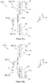
Figure 5(a) shows a schematic view of respective transfer limb portions within the power converter shown inFigure 1 in a first operating cycle of the conduit energy transfer mode; and -
Figure 5(b) shows a schematic view of the transfer limb portions shown inFigure 4(a) in a second operating cycle of the conduit energy transfer mode. - A HVDC power converter according to an embodiment of the invention is designated generally by
reference numeral 10, as shown inFigure 1 . - The
power converter 10 has first andsecond DC terminals DC transmission conduits DC network 20. In the embodiment shown, the first andsecond DC terminals DC transmission conduits second DC terminals - The
power converter 10 includes three converter limbs 22A, 22B, 22C each of which is associated with a respective phase a, b, c of a three-phase AC network 24 with which thepower converter 10 is, in use, connected. - More particularly, in the embodiment shown, each converter limb 22A, 22B, 22C extends between the first and
second DC terminals second limb portions corresponding AC terminal 30A, 30B, 30C, with eachAC terminal 30A, 30B, 30C being connected, in use, to a respective phase a, b, c of theaforementioned AC network 24. More particularly still, eachfirst limb portion first DC terminal 12 and thecorresponding AC terminal 30A, 30B, 30C while eachsecond limb portion 28A, 28B, 28C extends between thesecond DC terminal 14 and thecorresponding AC terminal 30A, 30B, 30C. - Power converters according to other embodiments of the invention may be configured to handle fewer than or more than three phases and hence may have a fewer or greater number of corresponding converter limbs.
- Returning to the
power converter 10 shown inFigure 1 , thelimb portions respective valves 32 that operate in cooperation with one another during normal use of thepower converter 10 to transfer power between the DC andAC networks - One
first limb portion 26B is designated as a firsttransfer limb portion 34 and one second limb portion 28B is designated as a second transfer limb portion 36, whereby eachrespective valve 32 therein is in the form of atransfer valve 38 that selectively allows current to flow therethrough in a first direction D1 while at all times allowing current to flow therethrough in a second direction D2 opposite the first direction D1. - In the embodiment shown, the first and second
transfer limb portions 34, 36 lie within the same converter limb 22B, although this need not necessarily be the case in other embodiments of the invention, i.e. the first transfer limb portion may lie in one converter limb while the second transfer limb portion lies in a different converter limb. Similarly, in still further embodiments of the invention multiple first limb portions may each be designated as a first transfer limb portion, and/or multiple second limb portions may each be designated as a second transfer limb portion. - In any event, returning to the embodiment shown, each
valve 32, including the designatedtransfer valves 38, is defined by a chain-link converter 40 which is formed from a plurality of series connectedchain link modules 42, as shown schematically inFigure 2 . - Each
chain link module 42 includes first and second individual switching elements 44, 46 that are electrically connected with an energy storage device 47, and more particularly are connected with the energy storage device 47 in a known half-bridge arrangement. The energy storage device 47 preferably is a capacitor. - Meanwhile, the first individual switching element 44 is a first active switching element and passive current check element pair 48, with the active switching element 50 taking the form of a semiconductor switch 52 and the passive current check element 54 taking the form of an anti-parallel diode 56 connected in parallel with the said semiconductor switch 52, while the second individual switching element 46 is a second active switching element and passive current check element pair 58, with the active switching element 50 again taking the form of a semiconductor switch 52 and the passive current check element 54 again taking the form of an anti-parallel diode 56 connected in parallel with the said semiconductor switch 52.
- In both instances, the semiconductor switch 52 preferably is an insulated-gate bipolar transistor (IGBT), although in other embodiments of the invention it might instead be a thyristor, a Light-Triggered Thyristor (LTT), a Gate Turn-Off thyristor (GTO), a Gate Commutated Thyristor (GCT) or an Integrated Gate Commutated Thyristor (IGCT), or a series-connected string of such switches.
- The second active switching element and passive current check element pair 58, in each
chain link module 42 of the chain-link converter 40 within eachtransfer valve 38, is configured within the correspondingchain link module 42 to selectively allow current to flow through the respectivechain link module 42 in the first direction D1, while at all times allowing current to flow through the respectivechain link module 42 in the second direction D2. Hence, the plurality of second active switching element and passive current check element pairs 58 within the chain-link converter 40 of eachtransfer valve 38 are able to combine to selectively allow current to flow through thecorresponding transfer valve 38 in the first direction D1, while at all times allowing current to flow through thecorresponding transfer valve 38 in the second direction D2. - In other embodiments of the invention, not shown, each transfer limb portion may include a valve in the form of a transfer valve that selectively allows current to flow therethrough in both a first direction while also only selectively allowing current to flow therethrough in a second direction opposite the first direction. Such transfer valves preferably are formed from a plurality of chain link modules, similar to those described hereinabove, but instead including additional individual switching elements which are connected with an energy storage device, e.g. a capacitor, in a known full bridge arrangement.
- In addition to the foregoing, the
power converter 10 includes atransfer inductor 60 that is electrically connected between thetransfer limb portions 34, 36 andground 62. Other embodiments of the invention, now shown, may include more than one transfer inductor, so connected between the transfer limb portions and ground. - In the particular embodiment shown, each
AC terminal 30A, 30B, 30C is connected to a first transformer winding 64 of atransformer 66 that is configured, in use, to connect thepower converter 10 to theAC network 24, and thetransfer inductor 60 extends between aneutral point 68 of the first transformer winding 64 andground 62, as shown inFigure 3 . Thetransformer 66 is a star-star connected transformer in which the first transformer winding 64 has a star arrangement and a second transformer winding 70 similarly has a star arrangement, although in other embodiments of the invention the transformer may have a different configuration, and the or each transfer inductor may correspondingly be connected in a different manner. - Returning to the embodiment shown, the
transfer inductor 60 takes the form of adedicated inductance component 72 which is solely configured to, in use while the power converter is operated in the conduit energy transfer mode, handle a transfer of energy between the first and secondDC transmission conduits - In other embodiments of the invention, the
transfer inductor 60 may instead be formed by an existing ground reactor 74, such a star-point reactor 76 which ordinarily forms a part of a star-star connected transformer. - In the embodiment shown, the
dedicated inductance component 72 is arranged in series with aswitch 78, which is preferably a further semiconductor switch or, more preferably still, a cost-effective fast mechanical switch. - The
power converter 10 additionally includes acontrol unit 80 that is programmed, in use, to operate thepower converter 10 in a conduit energy transfer mode. In the particular embodiment of the invention described, thecontrol unit 80 is programmed to operate thepower converter 10 in such a transfer mode following a fault condition in which the voltage carried by oneDC transmission conduit - For example, when the
power converter 10 is connected with a firstDC transmission conduit 16 that is carrying +300 kV and a secondDC transmission conduit 18 that is carrying -300 kV, and the secondDC transmission conduit 18 experiences a short-circuit fault 82, the voltage carried by the firstDC transmission conduit 16 will increase to approximately +584 kV while the voltage carried by the secondDC transmission conduit 18 reduces to approximately 0.4 kV, as shown inFigure 4 . - Following such a fault condition, the
control unit 80 operates thepower converter 10 in the conduit energy transfer mode, and more particularly is programmed to initially block eachvalve 32 to prevent the transfer of power between the DC andAC networks control unit 80 is programmed to turn off each semiconductor switch 52 in eachchain link module 42 of each chain-link converter 40 in eachvalve 32. - Any
AC circuit breaker 84 which might be operable to protect thepower converter 10, e.g. by isolating it from other power converters within a power transmission network, is also operated to provide such protection. - The
control unit 80 is additionally programmed to close theswitch 78 to place theinductance component 72, i.e. thetransfer inductor 60, in circuit between thetransfer limb portions 34, 36 andground 62. - Thereafter, the
control unit 80 is programmed to direct current to flow during a first operating cycle from aDC terminal DC transmission conduit first DC terminal 12 connected with the firstDC transmission conduit 16 which is now carrying the increased voltage, to thetransfer inductor 60, via the corresponding firsttransfer limb portion 34. - In practice, as shown in
Figure 5(a) , this means thecontrol unit 80 is programmed to close the semiconductor switch 52 in each second active switching element and passive current check element pair 58 in eachchain link module 42 of the chain-link converter 40 in thetransfer valve 38 within the firsttransfer limb portion 34, so that a first current I1 is able to flow in the first direction D1 from the first DC transmission conduit 16 (which is depicted as a capacitance inFigure 5(a) ) to thetransfer inductor 60, whereby energy is transferred from the firstDC transmission conduit 16 to thetransfer inductor 60. - The
control unit 80 is programmed to then direct current to flow during a second operating cycle from thetransfer inductor 60 to theDC terminal DC transmission conduit second DC terminal 14 connect with the secondDC transmission conduit 18 which is now carrying the reduced voltage, via the corresponding second transfer limb portion 36. - In practice, as shown in
Figure 5(b) , this means thecontrol unit 80 is programmed to open the semiconductor switch 52 in each second active switching element and passive current check element pair 58 in eachchain link module 42 of the chain-link converter 40 in thetransfer valve 38 within the firsttransfer limb portion 34. Such prevention of the flow of first current I1 thereby allows a transfer of energy to take place from thetransfer inductor 60 to the second DC transmission conduit 18 (which is again depicted as a capacitance inFigure 5(b) ), via a flow of second current I2 in the second direction D2 through thetransfer valve 38 in the second transfer limb portion 36 that extends between thesecond DC terminal 14 connected with the secondDC transmission conduit 18 now carrying the reduced voltage, and thetransfer inductor 60. - In addition, the
control unit 80 may be programmed, when operating thepower converter 10 in the conduit energy transfer mode, to repeat the first and second operating cycles. In one instance this may be to repeatedly transfer energy from the firstDC transmission conduit 16 to thetransfer inductor 60, and from thetransfer inductor 60 to the secondDC transmission conduit 18. In a second instance it may be to selectively transfer energy in both directions, i.e. from the firstDC transmission conduit 16 to the secondDC transmission conduit 18, and then in the opposite direction, i.e. from the secondDC transmission conduit 18 to the firstDC transmission conduit 16. - In the embodiment shown, a transfer of energy from the first
DC transmission conduit 16 to the secondDC transmission conduit 18, via thetransfer inductor 60, has the effect of reducing the magnitude of voltage carried by the firstDC transmission conduit 16 from approximately +584 kV to approximately +238 kV, while increasing the magnitude of voltage carried by the secondDC transmission conduit 18 from approximately 0.4 kV to approximately -233 kV, as shown inFigure 4 . - In other words, following operation of the
control unit 80 as set out above, the voltage carried by each of the first and secondDC transmission conduits power converter 10 is very close to being able to resume its normal operation. - In situations where the short-
circuit fault 82 afflicting the second DC transmission conduit 18 (or indeed the firstDC transmission conduit 16, as the case may be) extends for a long duration, the permanency of the fault can be determined by attempting to carry out the aforementioned voltage balancing exercise while monitoring the respective voltage of the first and secondDC transmission conduits DC transmission conduit 16 decreases, while operating thepower converter 10 in the conduit energy transfer mode, but the voltage of the secondDC transmission conduit 18 fails to increase correspondingly, then it can be concluded that the fault is a permanent one.
Claims (11)
- A HVDC power converter (10) comprising:first and second DC terminals (12, 14) for connection to corresponding first and second DC transmission conduits (16, 18) of a DC network (20);at least one converter limb (22A, 22B, 22C), the or each converter limb (22A, 22B, 22C) extending between the first and second DC terminals (12, 14), the or each converter limb (22A, 22B, 22C) including first and second limb portions (26A, 28A, 26B, 28B, 26C, 28C) separated by a respective AC terminal (30A, 30B, 30C), the AC terminal (30A, 30B, 30C) of the or each converter limb (22A, 22B, 22C) being for connection to a respective phase (a, b, c) of an AC network (24), the or each first limb portion (26A, 26B, 26C) extending between the first DC terminal (12) and a corresponding AC terminal (30A, 30B, 30C), the or each second limb portion (28A, 28B, 28C) extending between the second DC terminal (14) and a corresponding AC terminal (30A, 30B, 30C), the limb portions (26A, 28A, 26B, 28B, 26C, 28C) each including respective valves (32) that operate in cooperation with one another during normal use of the power converter (10) to transfer power between the DC and AC networks (20, 24), at least one first limb portion (26A, 26B, 26C) being designated as a first transfer limb portion (34) and at least one second limb portion (28A, 28B, 28C) being designated as a second transfer limb portion (36);at least one transfer inductor (60) electrically connected between the transfer limb portions (34, 36) and ground (62); anda control unit (80) programmed, while operating the power converter (10) in a conduit energy transfer mode, to:(a) direct current to flow during a first operating cycle from one of the first DC terminal (12) or the second DC terminal (14) to one or more transfer inductors (60), via a corresponding one of the or each first transfer limb portion (34) or the or each second transfer limb portion (36), whereby energy is transferred from the DC transmission conduit (16, 18) connected in use with the said one of the first DC terminal (12) or the second DC terminal (14) to the one or more transfer inductors (60); and(b) direct current to flow during a second operating cycle from the one or more transfer inductors (60) to the other of the first DC terminal (12) and the second DC terminal (14), via a corresponding other of the or each first transfer limb portion (34) and the or each second transfer limb portion (36), whereby energy is transferred from the one or more transfer inductors (60) to the DC transmission conduit (16, 18) connected in use with the said other of the first DC terminal (12) and the second DC terminal (14).
- A power converter (10) according to Claim 1 wherein the control unit (80) is programmed to:(a) direct current to flow during the first operating cycle from a DC terminal (12, 14) connected in use with the DC transmission conduit (16, 18) carrying a higher voltage to one or more transfer inductors (60), via the corresponding one of the or each first transfer limb portion (34) and the or each second transfer limb portion (36), whereby energy is transferred from the DC transmission conduit (16, 18) carrying the higher voltage to the one or more transfer inductors (60); and(b) direct current to flow during the second operating cycle from the one or more transfer inductors (60) to the DC terminal (12, 14) connected in use with the DC transmission conduit (16, 18) carrying a lower voltage, via the corresponding other of the or each first transfer limb portion (34) and the or each second transfer limb portion (36), whereby energy is transferred from the one or more transfer inductors (60) to the DC transmission conduit (16, 18) carrying the lower voltage.
- A power converter (10) according to Claim 2 wherein the control unit (80) is programmed to operate the power converter (10) in the conduit energy transfer mode following a fault condition in which the voltage carried in use by one DC transmission conduit (16, 18) reduces while the voltage carried by the other DC transmission conduit (16, 18) increases.
- A power converter (10) according to Claim 3 wherein the control unit (80) is programmed when operating the power converter (10) in the conduit energy transfer mode following a fault conduit to, as a first step, block each valve (32) to prevent the transfer of power between the DC and AC networks (20, 24).
- A power converter (10) according to any preceding claim wherein the control unit (80) is programmed to repeat the first and second operating cycles.
- A power converter (10) according to any preceding claim wherein the or each AC terminal (30A, 30B, 30C) is connected to a first transformer winding (64) of a transformer (66) configured, in use, to connect the power converter (10) to an AC network (24).
- A power converter (10) according to Claim 6 wherein a transfer inductor (60) extends between a neutral point (68) of the first transformer winding (64) and ground (62).
- A power converter (10) according to any preceding claim wherein at least one transfer inductor (60) takes the form of a dedicated inductance component (72) solely configured to in use handle the transfer of energy between respective DC transmission conduits (16, 18).
- A power converter according to Claim 8 wherein the or each dedicated inductance component (72) is arranged in series with a switch (78), and the control unit (80) is further programmed while operating the power converter (10) in the conduit energy transfer mode to close the or each switch (78) to place the corresponding inductance component (72) in circuit between the transfer limb portions (34, 36) and ground (62).
- A power converter (10) according to any preceding claim wherein each transfer limb portion (34, 36) includes a valve (32) in the form of a transfer valve (38) that selectively allows current (I1) to flow therethrough in a first direction (D1) while at all times allowing current (12) to flow therethrough in a second direction (D2) opposite the first direction (D1).
- A power converter (10) according to any of Claims 1 to 9 wherein each transfer limb portion (34, 36) includes a valve (32) in the form of a transfer valve (38) that selectively allows current (I1) to flow therethrough in both a first direction (D1) while also only selectively allowing current (I2) to flow therethrough in a second direction (D2) opposite the first direction (D1).
Priority Applications (3)
| Application Number | Priority Date | Filing Date | Title |
|---|---|---|---|
| EP18159235.3A EP3534523B1 (en) | 2018-02-28 | 2018-02-28 | Improvements in or relating to hvdc power converters |
| PCT/EP2019/053439 WO2019166219A1 (en) | 2018-02-28 | 2019-02-12 | Improvements in or relating to hvdc power converters |
| CN201980015768.7A CN111742482A (en) | 2018-02-28 | 2019-02-12 | Improvements in or related to HVDC power converters |
Applications Claiming Priority (1)
| Application Number | Priority Date | Filing Date | Title |
|---|---|---|---|
| EP18159235.3A EP3534523B1 (en) | 2018-02-28 | 2018-02-28 | Improvements in or relating to hvdc power converters |
Publications (2)
| Publication Number | Publication Date |
|---|---|
| EP3534523A1 true EP3534523A1 (en) | 2019-09-04 |
| EP3534523B1 EP3534523B1 (en) | 2022-02-16 |
Family
ID=61526639
Family Applications (1)
| Application Number | Title | Priority Date | Filing Date |
|---|---|---|---|
| EP18159235.3A Not-in-force EP3534523B1 (en) | 2018-02-28 | 2018-02-28 | Improvements in or relating to hvdc power converters |
Country Status (3)
| Country | Link |
|---|---|
| EP (1) | EP3534523B1 (en) |
| CN (1) | CN111742482A (en) |
| WO (1) | WO2019166219A1 (en) |
Citations (3)
| Publication number | Priority date | Publication date | Assignee | Title |
|---|---|---|---|---|
| WO2011006796A2 (en) * | 2009-07-17 | 2011-01-20 | Siemens Aktiengesellschaft | Star point reactor |
| WO2015024950A1 (en) * | 2013-08-21 | 2015-02-26 | Alstom Technology Ltd | Electric protection on ac side of hvdc |
| WO2017148794A1 (en) * | 2016-02-29 | 2017-09-08 | General Electric Technology Gmbh | Ground circuit in an ac network |
Family Cites Families (2)
| Publication number | Priority date | Publication date | Assignee | Title |
|---|---|---|---|---|
| CA2802933C (en) * | 2010-06-18 | 2018-01-02 | Alstom Technology Ltd | Converter for hvdc transmission and reactive power compensation |
| CN107431444A (en) * | 2015-03-18 | 2017-12-01 | 通用电器技术有限公司 | The improvement of electrical component or the improvement relevant with electrical component |
-
2018
- 2018-02-28 EP EP18159235.3A patent/EP3534523B1/en not_active Not-in-force
-
2019
- 2019-02-12 CN CN201980015768.7A patent/CN111742482A/en active Pending
- 2019-02-12 WO PCT/EP2019/053439 patent/WO2019166219A1/en not_active Ceased
Patent Citations (3)
| Publication number | Priority date | Publication date | Assignee | Title |
|---|---|---|---|---|
| WO2011006796A2 (en) * | 2009-07-17 | 2011-01-20 | Siemens Aktiengesellschaft | Star point reactor |
| WO2015024950A1 (en) * | 2013-08-21 | 2015-02-26 | Alstom Technology Ltd | Electric protection on ac side of hvdc |
| WO2017148794A1 (en) * | 2016-02-29 | 2017-09-08 | General Electric Technology Gmbh | Ground circuit in an ac network |
Also Published As
| Publication number | Publication date |
|---|---|
| WO2019166219A1 (en) | 2019-09-06 |
| EP3534523B1 (en) | 2022-02-16 |
| CN111742482A (en) | 2020-10-02 |
Similar Documents
| Publication | Publication Date | Title |
|---|---|---|
| EP2781013B1 (en) | A power electronic module | |
| EP3238315B1 (en) | Modular multi-level converter with thyristor valves | |
| KR101738032B1 (en) | Converter with active fault current limitation | |
| US11777401B2 (en) | Fault tolerant AC-DC chain-link converter | |
| EP3446400A1 (en) | Converter arrangement | |
| WO2018100051A1 (en) | Improvements in or relating to hvdc power converters | |
| US8830636B2 (en) | High voltage DC switchyard with semiconductor switches | |
| US20170264187A1 (en) | A voltage source converter | |
| WO2018145724A1 (en) | Protective circuit arrangement | |
| CN107925248B (en) | electrical components | |
| US20210359617A1 (en) | Electrical assembly | |
| US20180115253A1 (en) | Improvements in or relating to electrical assemblies | |
| EP3534523B1 (en) | Improvements in or relating to hvdc power converters | |
| WO2010069399A1 (en) | A voltage source converter | |
| EP3944450B1 (en) | Improvements in or relating to converter stations | |
| US12143028B2 (en) | Electrical assembly |
Legal Events
| Date | Code | Title | Description |
|---|---|---|---|
| PUAI | Public reference made under article 153(3) epc to a published international application that has entered the european phase |
Free format text: ORIGINAL CODE: 0009012 |
|
| STAA | Information on the status of an ep patent application or granted ep patent |
Free format text: STATUS: THE APPLICATION HAS BEEN PUBLISHED |
|
| AK | Designated contracting states |
Kind code of ref document: A1 Designated state(s): AL AT BE BG CH CY CZ DE DK EE ES FI FR GB GR HR HU IE IS IT LI LT LU LV MC MK MT NL NO PL PT RO RS SE SI SK SM TR |
|
| AX | Request for extension of the european patent |
Extension state: BA ME |
|
| STAA | Information on the status of an ep patent application or granted ep patent |
Free format text: STATUS: REQUEST FOR EXAMINATION WAS MADE |
|
| STAA | Information on the status of an ep patent application or granted ep patent |
Free format text: STATUS: EXAMINATION IS IN PROGRESS |
|
| 17P | Request for examination filed |
Effective date: 20200228 |
|
| RBV | Designated contracting states (corrected) |
Designated state(s): AL AT BE BG CH CY CZ DE DK EE ES FI FR GB GR HR HU IE IS IT LI LT LU LV MC MK MT NL NO PL PT RO RS SE SI SK SM TR |
|
| 17Q | First examination report despatched |
Effective date: 20200401 |
|
| GRAP | Despatch of communication of intention to grant a patent |
Free format text: ORIGINAL CODE: EPIDOSNIGR1 |
|
| STAA | Information on the status of an ep patent application or granted ep patent |
Free format text: STATUS: GRANT OF PATENT IS INTENDED |
|
| INTG | Intention to grant announced |
Effective date: 20210913 |
|
| GRAS | Grant fee paid |
Free format text: ORIGINAL CODE: EPIDOSNIGR3 |
|
| GRAA | (expected) grant |
Free format text: ORIGINAL CODE: 0009210 |
|
| STAA | Information on the status of an ep patent application or granted ep patent |
Free format text: STATUS: THE PATENT HAS BEEN GRANTED |
|
| AK | Designated contracting states |
Kind code of ref document: B1 Designated state(s): AL AT BE BG CH CY CZ DE DK EE ES FI FR GB GR HR HU IE IS IT LI LT LU LV MC MK MT NL NO PL PT RO RS SE SI SK SM TR |
|
| REG | Reference to a national code |
Ref country code: GB Ref legal event code: FG4D |
|
| REG | Reference to a national code |
Ref country code: CH Ref legal event code: EP |
|
| REG | Reference to a national code |
Ref country code: DE Ref legal event code: R096 Ref document number: 602018030796 Country of ref document: DE |
|
| REG | Reference to a national code |
Ref country code: AT Ref legal event code: REF Ref document number: 1469511 Country of ref document: AT Kind code of ref document: T Effective date: 20220315 |
|
| REG | Reference to a national code |
Ref country code: IE Ref legal event code: FG4D |
|
| PGFP | Annual fee paid to national office [announced via postgrant information from national office to epo] |
Ref country code: GB Payment date: 20220323 Year of fee payment: 5 Ref country code: DE Payment date: 20220217 Year of fee payment: 5 |
|
| REG | Reference to a national code |
Ref country code: SE Ref legal event code: TRGR |
|
| PGFP | Annual fee paid to national office [announced via postgrant information from national office to epo] |
Ref country code: FR Payment date: 20220322 Year of fee payment: 5 |
|
| REG | Reference to a national code |
Ref country code: LT Ref legal event code: MG9D |
|
| REG | Reference to a national code |
Ref country code: NL Ref legal event code: MP Effective date: 20220216 |
|
| REG | Reference to a national code |
Ref country code: AT Ref legal event code: MK05 Ref document number: 1469511 Country of ref document: AT Kind code of ref document: T Effective date: 20220216 |
|
| PG25 | Lapsed in a contracting state [announced via postgrant information from national office to epo] |
Ref country code: RS Free format text: LAPSE BECAUSE OF FAILURE TO SUBMIT A TRANSLATION OF THE DESCRIPTION OR TO PAY THE FEE WITHIN THE PRESCRIBED TIME-LIMIT Effective date: 20220216 Ref country code: PT Free format text: LAPSE BECAUSE OF FAILURE TO SUBMIT A TRANSLATION OF THE DESCRIPTION OR TO PAY THE FEE WITHIN THE PRESCRIBED TIME-LIMIT Effective date: 20220616 Ref country code: NO Free format text: LAPSE BECAUSE OF FAILURE TO SUBMIT A TRANSLATION OF THE DESCRIPTION OR TO PAY THE FEE WITHIN THE PRESCRIBED TIME-LIMIT Effective date: 20220516 Ref country code: NL Free format text: LAPSE BECAUSE OF FAILURE TO SUBMIT A TRANSLATION OF THE DESCRIPTION OR TO PAY THE FEE WITHIN THE PRESCRIBED TIME-LIMIT Effective date: 20220216 Ref country code: LT Free format text: LAPSE BECAUSE OF FAILURE TO SUBMIT A TRANSLATION OF THE DESCRIPTION OR TO PAY THE FEE WITHIN THE PRESCRIBED TIME-LIMIT Effective date: 20220216 Ref country code: HR Free format text: LAPSE BECAUSE OF FAILURE TO SUBMIT A TRANSLATION OF THE DESCRIPTION OR TO PAY THE FEE WITHIN THE PRESCRIBED TIME-LIMIT Effective date: 20220216 Ref country code: ES Free format text: LAPSE BECAUSE OF FAILURE TO SUBMIT A TRANSLATION OF THE DESCRIPTION OR TO PAY THE FEE WITHIN THE PRESCRIBED TIME-LIMIT Effective date: 20220216 Ref country code: BG Free format text: LAPSE BECAUSE OF FAILURE TO SUBMIT A TRANSLATION OF THE DESCRIPTION OR TO PAY THE FEE WITHIN THE PRESCRIBED TIME-LIMIT Effective date: 20220516 |
|
| PG25 | Lapsed in a contracting state [announced via postgrant information from national office to epo] |
Ref country code: PL Free format text: LAPSE BECAUSE OF FAILURE TO SUBMIT A TRANSLATION OF THE DESCRIPTION OR TO PAY THE FEE WITHIN THE PRESCRIBED TIME-LIMIT Effective date: 20220216 Ref country code: LV Free format text: LAPSE BECAUSE OF FAILURE TO SUBMIT A TRANSLATION OF THE DESCRIPTION OR TO PAY THE FEE WITHIN THE PRESCRIBED TIME-LIMIT Effective date: 20220216 Ref country code: GR Free format text: LAPSE BECAUSE OF FAILURE TO SUBMIT A TRANSLATION OF THE DESCRIPTION OR TO PAY THE FEE WITHIN THE PRESCRIBED TIME-LIMIT Effective date: 20220517 Ref country code: FI Free format text: LAPSE BECAUSE OF FAILURE TO SUBMIT A TRANSLATION OF THE DESCRIPTION OR TO PAY THE FEE WITHIN THE PRESCRIBED TIME-LIMIT Effective date: 20220216 Ref country code: AT Free format text: LAPSE BECAUSE OF FAILURE TO SUBMIT A TRANSLATION OF THE DESCRIPTION OR TO PAY THE FEE WITHIN THE PRESCRIBED TIME-LIMIT Effective date: 20220216 |
|
| PG25 | Lapsed in a contracting state [announced via postgrant information from national office to epo] |
Ref country code: IS Free format text: LAPSE BECAUSE OF FAILURE TO SUBMIT A TRANSLATION OF THE DESCRIPTION OR TO PAY THE FEE WITHIN THE PRESCRIBED TIME-LIMIT Effective date: 20220617 |
|
| REG | Reference to a national code |
Ref country code: CH Ref legal event code: PL |
|
| REG | Reference to a national code |
Ref country code: BE Ref legal event code: MM Effective date: 20220228 |
|
| PG25 | Lapsed in a contracting state [announced via postgrant information from national office to epo] |
Ref country code: SM Free format text: LAPSE BECAUSE OF FAILURE TO SUBMIT A TRANSLATION OF THE DESCRIPTION OR TO PAY THE FEE WITHIN THE PRESCRIBED TIME-LIMIT Effective date: 20220216 Ref country code: SK Free format text: LAPSE BECAUSE OF FAILURE TO SUBMIT A TRANSLATION OF THE DESCRIPTION OR TO PAY THE FEE WITHIN THE PRESCRIBED TIME-LIMIT Effective date: 20220216 Ref country code: RO Free format text: LAPSE BECAUSE OF FAILURE TO SUBMIT A TRANSLATION OF THE DESCRIPTION OR TO PAY THE FEE WITHIN THE PRESCRIBED TIME-LIMIT Effective date: 20220216 Ref country code: LU Free format text: LAPSE BECAUSE OF NON-PAYMENT OF DUE FEES Effective date: 20220228 Ref country code: EE Free format text: LAPSE BECAUSE OF FAILURE TO SUBMIT A TRANSLATION OF THE DESCRIPTION OR TO PAY THE FEE WITHIN THE PRESCRIBED TIME-LIMIT Effective date: 20220216 Ref country code: DK Free format text: LAPSE BECAUSE OF FAILURE TO SUBMIT A TRANSLATION OF THE DESCRIPTION OR TO PAY THE FEE WITHIN THE PRESCRIBED TIME-LIMIT Effective date: 20220216 Ref country code: CZ Free format text: LAPSE BECAUSE OF FAILURE TO SUBMIT A TRANSLATION OF THE DESCRIPTION OR TO PAY THE FEE WITHIN THE PRESCRIBED TIME-LIMIT Effective date: 20220216 |
|
| REG | Reference to a national code |
Ref country code: DE Ref legal event code: R097 Ref document number: 602018030796 Country of ref document: DE |
|
| PG25 | Lapsed in a contracting state [announced via postgrant information from national office to epo] |
Ref country code: MC Free format text: LAPSE BECAUSE OF FAILURE TO SUBMIT A TRANSLATION OF THE DESCRIPTION OR TO PAY THE FEE WITHIN THE PRESCRIBED TIME-LIMIT Effective date: 20220216 Ref country code: AL Free format text: LAPSE BECAUSE OF FAILURE TO SUBMIT A TRANSLATION OF THE DESCRIPTION OR TO PAY THE FEE WITHIN THE PRESCRIBED TIME-LIMIT Effective date: 20220216 |
|
| PLBE | No opposition filed within time limit |
Free format text: ORIGINAL CODE: 0009261 |
|
| STAA | Information on the status of an ep patent application or granted ep patent |
Free format text: STATUS: NO OPPOSITION FILED WITHIN TIME LIMIT |
|
| 26N | No opposition filed |
Effective date: 20221117 |
|
| PG25 | Lapsed in a contracting state [announced via postgrant information from national office to epo] |
Ref country code: LI Free format text: LAPSE BECAUSE OF NON-PAYMENT OF DUE FEES Effective date: 20220228 Ref country code: IE Free format text: LAPSE BECAUSE OF NON-PAYMENT OF DUE FEES Effective date: 20220228 Ref country code: CH Free format text: LAPSE BECAUSE OF NON-PAYMENT OF DUE FEES Effective date: 20220228 |
|
| PG25 | Lapsed in a contracting state [announced via postgrant information from national office to epo] |
Ref country code: SI Free format text: LAPSE BECAUSE OF FAILURE TO SUBMIT A TRANSLATION OF THE DESCRIPTION OR TO PAY THE FEE WITHIN THE PRESCRIBED TIME-LIMIT Effective date: 20220216 Ref country code: BE Free format text: LAPSE BECAUSE OF NON-PAYMENT OF DUE FEES Effective date: 20220228 |
|
| PG25 | Lapsed in a contracting state [announced via postgrant information from national office to epo] |
Ref country code: IT Free format text: LAPSE BECAUSE OF FAILURE TO SUBMIT A TRANSLATION OF THE DESCRIPTION OR TO PAY THE FEE WITHIN THE PRESCRIBED TIME-LIMIT Effective date: 20220216 |
|
| PGFP | Annual fee paid to national office [announced via postgrant information from national office to epo] |
Ref country code: SE Payment date: 20220217 Year of fee payment: 5 |
|
| REG | Reference to a national code |
Ref country code: DE Ref legal event code: R119 Ref document number: 602018030796 Country of ref document: DE |
|
| GBPC | Gb: european patent ceased through non-payment of renewal fee |
Effective date: 20230228 |
|
| REG | Reference to a national code |
Ref country code: SE Ref legal event code: EUG |
|
| PG25 | Lapsed in a contracting state [announced via postgrant information from national office to epo] |
Ref country code: GB Free format text: LAPSE BECAUSE OF NON-PAYMENT OF DUE FEES Effective date: 20230228 |
|
| PG25 | Lapsed in a contracting state [announced via postgrant information from national office to epo] |
Ref country code: SE Free format text: LAPSE BECAUSE OF NON-PAYMENT OF DUE FEES Effective date: 20230301 Ref country code: GB Free format text: LAPSE BECAUSE OF NON-PAYMENT OF DUE FEES Effective date: 20230228 Ref country code: FR Free format text: LAPSE BECAUSE OF NON-PAYMENT OF DUE FEES Effective date: 20230228 Ref country code: DE Free format text: LAPSE BECAUSE OF NON-PAYMENT OF DUE FEES Effective date: 20230901 |
|
| PG25 | Lapsed in a contracting state [announced via postgrant information from national office to epo] |
Ref country code: MK Free format text: LAPSE BECAUSE OF FAILURE TO SUBMIT A TRANSLATION OF THE DESCRIPTION OR TO PAY THE FEE WITHIN THE PRESCRIBED TIME-LIMIT Effective date: 20220216 Ref country code: CY Free format text: LAPSE BECAUSE OF FAILURE TO SUBMIT A TRANSLATION OF THE DESCRIPTION OR TO PAY THE FEE WITHIN THE PRESCRIBED TIME-LIMIT Effective date: 20220216 |
|
| PG25 | Lapsed in a contracting state [announced via postgrant information from national office to epo] |
Ref country code: HU Free format text: LAPSE BECAUSE OF FAILURE TO SUBMIT A TRANSLATION OF THE DESCRIPTION OR TO PAY THE FEE WITHIN THE PRESCRIBED TIME-LIMIT; INVALID AB INITIO Effective date: 20180228 |
|
| PG25 | Lapsed in a contracting state [announced via postgrant information from national office to epo] |
Ref country code: MT Free format text: LAPSE BECAUSE OF FAILURE TO SUBMIT A TRANSLATION OF THE DESCRIPTION OR TO PAY THE FEE WITHIN THE PRESCRIBED TIME-LIMIT Effective date: 20220216 |
|
| PG25 | Lapsed in a contracting state [announced via postgrant information from national office to epo] |
Ref country code: TR Free format text: LAPSE BECAUSE OF FAILURE TO SUBMIT A TRANSLATION OF THE DESCRIPTION OR TO PAY THE FEE WITHIN THE PRESCRIBED TIME-LIMIT Effective date: 20220216 |