EP3534501A1 - Insulator for armature, motor - Google Patents
Insulator for armature, motor Download PDFInfo
- Publication number
- EP3534501A1 EP3534501A1 EP17865624.5A EP17865624A EP3534501A1 EP 3534501 A1 EP3534501 A1 EP 3534501A1 EP 17865624 A EP17865624 A EP 17865624A EP 3534501 A1 EP3534501 A1 EP 3534501A1
- Authority
- EP
- European Patent Office
- Prior art keywords
- insulator
- coils
- armature
- power supply
- respect
- Prior art date
- Legal status (The legal status is an assumption and is not a legal conclusion. Google has not performed a legal analysis and makes no representation as to the accuracy of the status listed.)
- Granted
Links
Images





Classifications
-
- H—ELECTRICITY
- H02—GENERATION; CONVERSION OR DISTRIBUTION OF ELECTRIC POWER
- H02K—DYNAMO-ELECTRIC MACHINES
- H02K3/00—Details of windings
- H02K3/32—Windings characterised by the shape, form or construction of the insulation
- H02K3/325—Windings characterised by the shape, form or construction of the insulation for windings on salient poles, such as claw-shaped poles
-
- H—ELECTRICITY
- H02—GENERATION; CONVERSION OR DISTRIBUTION OF ELECTRIC POWER
- H02K—DYNAMO-ELECTRIC MACHINES
- H02K3/00—Details of windings
- H02K3/32—Windings characterised by the shape, form or construction of the insulation
- H02K3/38—Windings characterised by the shape, form or construction of the insulation around winding heads, equalising connectors, or connections thereto
-
- H—ELECTRICITY
- H02—GENERATION; CONVERSION OR DISTRIBUTION OF ELECTRIC POWER
- H02K—DYNAMO-ELECTRIC MACHINES
- H02K3/00—Details of windings
- H02K3/04—Windings characterised by the conductor shape, form or construction, e.g. with bar conductors
- H02K3/18—Windings for salient poles
-
- H—ELECTRICITY
- H02—GENERATION; CONVERSION OR DISTRIBUTION OF ELECTRIC POWER
- H02K—DYNAMO-ELECTRIC MACHINES
- H02K3/00—Details of windings
- H02K3/32—Windings characterised by the shape, form or construction of the insulation
- H02K3/34—Windings characterised by the shape, form or construction of the insulation between conductors or between conductor and core, e.g. slot insulation
-
- H—ELECTRICITY
- H02—GENERATION; CONVERSION OR DISTRIBUTION OF ELECTRIC POWER
- H02K—DYNAMO-ELECTRIC MACHINES
- H02K3/00—Details of windings
- H02K3/46—Fastening of windings on the stator or rotor structure
- H02K3/52—Fastening salient pole windings or connections thereto
- H02K3/521—Fastening salient pole windings or connections thereto applicable to stators only
- H02K3/522—Fastening salient pole windings or connections thereto applicable to stators only for generally annular cores with salient poles
-
- H—ELECTRICITY
- H02—GENERATION; CONVERSION OR DISTRIBUTION OF ELECTRIC POWER
- H02K—DYNAMO-ELECTRIC MACHINES
- H02K5/00—Casings; Enclosures; Supports
- H02K5/04—Casings or enclosures characterised by the shape, form or construction thereof
- H02K5/22—Auxiliary parts of casings not covered by groups H02K5/06-H02K5/20, e.g. shaped to form connection boxes or terminal boxes
-
- H—ELECTRICITY
- H02—GENERATION; CONVERSION OR DISTRIBUTION OF ELECTRIC POWER
- H02K—DYNAMO-ELECTRIC MACHINES
- H02K21/00—Synchronous motors having permanent magnets; Synchronous generators having permanent magnets
- H02K21/12—Synchronous motors having permanent magnets; Synchronous generators having permanent magnets with stationary armatures and rotating magnets
- H02K21/22—Synchronous motors having permanent magnets; Synchronous generators having permanent magnets with stationary armatures and rotating magnets with magnets rotating around the armatures, e.g. flywheel magnetos
-
- H—ELECTRICITY
- H02—GENERATION; CONVERSION OR DISTRIBUTION OF ELECTRIC POWER
- H02K—DYNAMO-ELECTRIC MACHINES
- H02K2203/00—Specific aspects not provided for in the other groups of this subclass relating to the windings
- H02K2203/06—Machines characterised by the wiring leads, i.e. conducting wires for connecting the winding terminations
-
- H—ELECTRICITY
- H02—GENERATION; CONVERSION OR DISTRIBUTION OF ELECTRIC POWER
- H02K—DYNAMO-ELECTRIC MACHINES
- H02K2203/00—Specific aspects not provided for in the other groups of this subclass relating to the windings
- H02K2203/09—Machines characterised by wiring elements other than wires, e.g. bus rings, for connecting the winding terminations
-
- H—ELECTRICITY
- H02—GENERATION; CONVERSION OR DISTRIBUTION OF ELECTRIC POWER
- H02K—DYNAMO-ELECTRIC MACHINES
- H02K2203/00—Specific aspects not provided for in the other groups of this subclass relating to the windings
- H02K2203/12—Machines characterised by the bobbins for supporting the windings
-
- H—ELECTRICITY
- H02—GENERATION; CONVERSION OR DISTRIBUTION OF ELECTRIC POWER
- H02K—DYNAMO-ELECTRIC MACHINES
- H02K2213/00—Specific aspects, not otherwise provided for and not covered by codes H02K2201/00 - H02K2211/00
- H02K2213/03—Machines characterised by numerical values, ranges, mathematical expressions or similar information
Definitions
- the present invention relates to an insulator used for an armature.
- Patent Document 1 there is a technique in which, in an armature provided with a plurality of armature windings (hereinafter also referred to as "coils") which are annularly arranged, pins are correspondingly provided for the coils.
- This configuration is provided because an end of one of a pair of coils arranged adjacent to each other and an end of the other coil are connected to each other.
- such a connection is achieved by winding a pair of coils with a continuous wire.
- Fig. 12 is a connection diagram which shows connection of three-phase coils in a 12-pole armature and which is disclosed in, for example, Patent Document 1.
- a coil pair Lua has coils Lu1 and Lu2 connected in series with each other, and the coils Lu1 and Lu2 are disposed adjacent to each other in the armature.
- a coil pair Lub has coils Lu3 and Lu4
- a coil pair Lva has coils Lv1 and Lv2
- a coil pair Lvb has coils Lv3 and Lv4
- a coil pair Lwa has coils Lw1 and Lw2
- a coil pair Lwb has coils Lw3 and Lw4.
- connection of a pair of coils inside these coil pairs is achieved by a continuous wire as described above.
- a connection between the coil pairs (a so-called "jumper line”) needs to be interposed by pins. This is because the coil pair Lua and the coil pair Lub which are connected in series are arranged apart from each other by 180 degrees. The same applies to a jumper line between the coil pairs Lva and Lvb and a jumper line between the coil pairs Lwa and Lwb.
- Patent Document 1 uses a printed circuit board.
- the printed circuit board is provided with lands to which the pins connected to the ends of the coils are connected, and the lands are connected to each other with a wiring pattern on the printed circuit board.
- the jumper line is achieved by the pins and the wiring pattern on the printed circuit board.
- solder necessary for electrically connecting the lands and the pins is also required to have mechanical strength to fix the printed circuit board to the pins. In other words, if the solder is damaged by an external force applied between the printed circuit board and the pins, the electrical connection may also be impaired due to such damage.
- the insulator has a plurality of holes (HI to H12) that are penetrated by the pins in the axial direction, and a plurality of first guide portions (32F, 32A, 32C; 32F, 32B, 32C) that guide at least three (Pn, Pxu, Pxw; Pn, Pxv, Pxw) of the jumper lines in the circumferential direction with respect to the axis at different positions in a radial direction around the axis.
- first guide portions 32F, 32A, 32C; 32F, 32B, 32C
- the insulator for an armature according to the first aspect is interposed between the coils and connection portions between the jumper lines and the pins in the axial direction.
- At least one of the first guide portions has at least one protrusion (31j, 31k, 32a to 32f; 31a, 32a to 32f, 32i, 32j) protruding toward an outer periphery along the radial direction.
- the insulator for an armature in the insulator for an armature according to any one of the first to third aspects, at least one of the pins functions as a power supply pin to which one end of a power supply line (Cu, Cw) is connected together with the one end of one of the coils.
- the insulator for an armature further includes at least one second guide portion (32D, 32E) for guiding the power supply line in the circumferential direction.
- the second guide portion has at least one protrusion (32g, 32h) protruding toward the outer periphery along the radial direction.
- the one end of the power supply line and the one end of one of the coils are targets to be bound to the power supply pin with another wire, at the power supply pin.
- the insulator for an armature is interposed between the binding position and the coil in the axial direction.
- one of the coils is wound around a second insulator (6).
- the insulator for an armature further includes an engagement part (39) to be engaged with the second insulator.
- the insulator for an armature is fixed to the second insulator in the axial direction by engagement between the second insulator and the engagement part in the axial direction.
- the insulator for an armature according to the first aspect of the present invention eliminates a need to use a printed circuit board for connection, and guides jumper lines without an increase in an axial dimension. Moreover, even if an external force is applied to the insulator for an armature, the connection between the coils is prevented from being impaired.
- the insulator for an armature according to the second aspect of the present invention increases an insulation distance from the coils in many areas of the jumper lines.
- the insulator for an armature according to the third aspect of the present invention inhibits the jumper lines from moving away from the coils.
- the insulator for an armature according to the fourth aspect of the present invention eliminates a need to use a printed circuit board for connection, and guides the power supply line without an increase in an axial dimension.
- the insulator for an armature according to the fifth aspect of the present invention inhibits the power supply line from moving away from the coils.
- the insulator for an armature according to the sixth aspect of the present invention makes it easy to connect one end of the power supply line and one end of the coil.
- the insulator for an armature according to the seventh aspect of the present invention is highly effective in preventing the connection between the coils from being impaired even if an external force is applied to the insulator for an armature.
- Fig. 1 is a plan view showing an armature 100 employing an insulator 3 for an armature according to the first embodiment, as viewed along an axial direction J parallel to an axis J0 of the armature.
- the armature 100 has an inner edge 10 around the axis J0.
- a plurality of coils Lu1 to Lu4, Lv1 to Lv4, and Lw1 to Lw4 are annularly arranged. These coils are concentratedly wound around teeth Tu1 to Tu4, Tv1 to Tv4, and Tw1 to Tw4, respectively.
- the coils Lu1, Lu2, Lw1, Lw2, Lv3, Lv4, Lu3, Lu4, Lw3, Lw4, Lv1, and Lv2 are arranged counterclockwise in this order. Note that, in Fig. 1 , the wire constituting each coil is schematically shown as a unit.
- coils Lu1 and Lu2 form a coil pair Lua
- the coils Lw1 and Lw2 form a coil pair Lwa
- the coils Lv3 and Lv4 form a coil pair Lvb
- the coils Lu3 and Lu4 form a coil pair Lub
- the coils Lw3 and Lw4 form a coil pair Lwb
- the coils Lv1 and Lv2 form a coil pair Lva (see also Fig. 12 ).
- the coil pairs Lua and Lub are connected to each other such that the winding-start-side ends of the wires constituting the respective coil pairs are connected to each other at a connection point Xu. That is, the coils Lu1 and Lu3 are connected at the connection point Xu. As a result, the coils Lu2, Lu1, Lu3, and Lu4 are connected in series in this order.
- the coil pairs Lva and Lvb are connected to each other such that the winding-end-side ends of the wires constituting the respective coil pairs are connected to each other at a connection point Xv. That is, the coils Lv2 and Lv4 are connected at the connection point Xv. As a result, the coils Lv1, Lv2, Lv4, and Lv3 are connected in series in this order.
- the coil pairs Lwa and Lwb are connected to each other such that the winding-end-side ends of the wires constituting the respective coil pairs are connected to each other at a connection point Xw. That is, the coils Lw2 and Lw4 are connected at the connection point Xw. As a result, the coils Lw1, Lw2, Lw4, and Lw3 are connected in series in this order.
- the winding-end-side end of the wire constituting the coil pair Lub, the winding-start-side end of the wire constituting the coil pair Lvb, and the winding-start-side end of the wire constituting the coil pair Lwb are connected at a neutral point N. That is, the coils Lu4, Lv3, and Lw3 are connected at the neutral point N.
- the connection points Xu, Xv, and Xw and the neutral point N in the connection diagram are achieved by jumper lines Pxu, Pxv, and Pxw in the actual armature, as shown in Fig. 1 .
- the teeth Tu1 to Tu4, Tv1 to Tv4, and Tw1 to Tw4 generate a rotating magnetic field directed toward the outer circumferential side of these teeth (outwardly along the radial direction around the axis J0) (see Patent Document 1). That is, the coils Lu1 to Lu4, Lv1 to Lv4, and Lw1 to Lw4 constitute an armature used for an outer rotor motor.
- the insulator 3 for an armature is provided so as to align with the coils Lu1 to Lu4, Lv1 to Lv4, and Lw1 to Lw4 in the axial direction J.
- the insulator 3 for an armature is provided on the front side of the paper to the coils Lu1 to Lu4, Lv1 to Lv4, and Lw1 to Lw4.
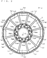
- Fig. 2 is a plan view showing a state where the insulator 3 for an armature is removed from the armature shown in Fig. 1 . It is to be noted that Fig. 2 also shows lines indicating bent parts and chamfered parts which are not shown in Fig. 1 for avoiding complexity. In the coils Lu1 to Lu4, Lv1 to Lv4 and Lw1 to Lw4, the portions where the outer shapes are bent are indicated by double lines, and the double lines do not represent wires.
- Pins Puas, Puae, Pwas, Pwae, Pvbs, Pvbe, Pubs, Pube, Pwbs, Pwbe, Pvas, and Pvae are connected to the ends of corresponding coils Lu1, Lu2, Lw1, Lw2, Lv3, Lv4, Lu3, Lu4, Lw3, Lw4, Lv1, and Lv2.
- the winding-start-side end of the wire constituting the coil pair Lua is connected to the pin Puas
- the winding-end-side end of the wire constituting the coil pair Lua is connected to the pin Puae
- the winding-start-side end of the wire constituting the coil pair Lub is connected to the pin Pubs
- the winding-end-side end of the wire constituting the coil pair Lub is connected to the pin Pube
- the winding-start-side end of the wire constituting the coil pair Lva is connected to the pin Pvas
- the winding-end-side end of the wire constituting the coil pair Lva is connected to the pin Pvae
- the winding-start-side end of the wire constituting the coil pair Lvb is connected to the pin Pvbs
- the winding-end-side end of the wire constituting the coil pair Lvb is connected to the pin Pvbe
- the winding-start-side end of the wire constituting the coil pair Lwa is connected to the pin Pwas
- the wires and the pins are specifically connected by soldering. Note that, in order to make it easy to secure electrical conduction, it is desirable that a composition of the pin around which the wire is wound is soldered.
- the insulator 3 for an armature has a plurality of holes H1 to H12 which are respectively penetrated by the pins Puas, Puae, Pwas, Pwae, Pvbs, Pvbe, Pubs, Pube, Pwbs, Pwbe, Pvas, and Pvae in the axial direction J.
- the jumper line Pxu is laid between the holes H2 and H8 which are penetrated by the pins Puas and Pubs, respectively.
- the jumper line Pxv is laid between the holes H1 and H7 which are penetrated by the pins Pvae and Pvbe, respectively.
- the jumper line Pxw is laid between the holes H5 and H11 which are penetrated by the pins Pwae and Pwbe pass, respectively.
- the jumper line Pn is laid between the holes H9, H6 and H10 which are penetrated by the pins Pube, Pvbs and Pwbs, respectively.
- the insulator 3 for an armature includes a guide portion 32A for guiding the jumper line Pxu, a guide portion 32B for guiding the jumper line Pxv, a guide portion 32C for guiding the jumper line Pxw, and a guide portion 32F for guiding the jumper line Pn.
- the insulator 3 for an armature has a base 31 and a protruding portion 32 that protrudes from the base 31 toward the front side of the paper (that is, toward the side opposite to the coils Lu1 to Lu4, Lv1 to Lv4, and Lw1 to Lw4 in the axial direction J).
- the base 31 is shown by coarse dots
- the protruding portion 32 is shown by two types of fine dots.
- the part shown by finer dots of the two types of fine dots indicates an area (described in detail later) of the protruding portion 32 protruding further toward the front side of the paper.
- jumper lines Pn, Pxu, Pxv, and Pxw portions which are laid on the side of coils Lu1 to Lu4, Lv1 to Lv4, and Lw1 to Lw4 with respect to the insulator 3 for an armature are shown by broken lines, regardless of whether or not they are hidden lines.
- connection portions between the jumper line Pxu and the pins Puas and Pubs, connection portions between the jumper line Pxv and the pins Pvae and Pvbe, and connection portions between the jumper line Pxw and the pins Pwae and Pwbe are all located on the side opposite to the coils Lu1 to Lu4, Lv1 to Lv4, and Lw1 to Lw4 with respect to the insulator 3 for an armature.
- the insulator 3 for an armature is interposed between these connection portions and the coils Lu1 to Lu4, Lv1 to Lv4 and Lw1 to Lw4 in the axial direction J.
- Such interposition is desirable from the viewpoint of increasing an insulation distance from the coils Lu1 to Lu4, Lv1 to Lv4, and Lw1 to Lw4 in many portions of the jumper lines Pn, Pxu, Pxv, and Pxw.
- the guide portion 32A has the protruding portion 32 protruding from the base 31 on a hole H4 side with respect to the hole H5.
- the jumper line Pxu which extends from the hole H2 through an area between the holes H4 and H5 toward the outer periphery and then is bent counterclockwise in the circumferential direction.
- the guide portion 32A has the protruding portion 32 protruding from the base 31 on a hole H7 side with respect to the hole H8. By being guided by this portion, the jumper line Pxu which extends from the hole H8 toward the outer periphery and then is bent clockwise in the circumferential direction. This portion also has a protrusion 32j protruding toward the outer periphery.
- the guide portion 32A may have the protruding portion 32 protruding from the base 31 on the outer peripheral side with respect to the holes H6 and H7.
- This portion guides the jumper line Pxu to the outer peripheral side with respect to the holes H5 to H8.
- the protruding portion 32 is not provided (regions where protrusions 31k and 31j protruding toward the outer periphery is exposed in the base 31) on the outer peripheral side between the holes H5 and H6 and on the outer peripheral side between the holes H7 and H8.
- the jumper line Pxu is laid on the side of the coils Lu3 and Lv3 with respect to the protrusions 31j and 31k.
- the protrusions 31j and 31k inhibit the jumper line Pxu from moving away from the coils Lu3 and Lv3. Such inhibition is desirable from the viewpoint of preventing the jumper line Pxu from being disengaged from the guide portion 32A.
- the protrusion 32j is desirable from the viewpoint of preventing the jumper line Pxv from being disengaged from a guide portion 32B described later.
- the guide portion 32B has the protruding portion 32 protruding from the base 31 on a hole H12 side with respect to the hole H11.
- the jumper line Pxv extends from the inner peripheral side toward the outer peripheral side between the holes H11 and H12 and then is bent clockwise in the circumferential direction.
- the guide portion 32B has the protruding portion 32 protruding from the base 31 on the outer peripheral side with respect to the holes H8 to H11. This portion guides the jumper line Pxv to the outer peripheral side with respect to the holes H8 to H11. However, in order to lay the jumper lines Pxu and Pxw on the base 31 side with respect to the protruding portion 32, there are regions where the protruding portion 32 is not provided on the outer peripheral side with respect to the hole H8 and on the outer peripheral side between the holes H10 and H11 (regions where a protrusion 31a protruding toward the outer periphery is exposed in the base 31).
- the jumper line Pxv is laid on the coil Lw4 side with respect to the protrusion 31a.
- the protrusion 31a inhibits the jumper line Pxv from moving away from the coil Lw4. Such inhibition is desirable from the viewpoint of preventing the jumper line Pxv from being disengaged from the guide portion 32B.
- a protrusion 32i which is a part of the protruding portion 32 and which protrudes toward the front side of the paper and toward the outer periphery on the outer peripheral side with respect to the hole H9.
- the protrusion 32i can also be regarded as the guide portion 32B.
- the jumper line Pxv is laid on the coil Lu4 side with respect to the protrusion 32i and the movement of the jumper line Pxv in a direction away from the coil Lu4 is inhibited.
- the guide portion 32B has a protrusion 32a protruding toward the outer periphery on the outer peripheral side between the holes H10 and H11.
- the protrusion 32a is desirable from the viewpoint of preventing the jumper line Pxw from being disengaged from a guide portion 32C described later.
- the guide portion 32C has the protruding portion 32 protruding from the base 31 on the outer peripheral side with respect to the holes H6 to H10 and on the outer peripheral side with respect to the guide portions 32A and 32B. This portion guides the jumper line Pxw to the outer peripheral side with respect to the holes H6 to H10.
- the guide portion 32C has a protrusion 32b formed near the outer peripheral side with respect to the hole H9 so as to protrude toward the outer periphery, a protrusion 32c formed near the outer peripheral side with respect to the hole H8 so as to protrude toward the outer periphery, a protrusion 32d formed near the outer peripheral side with respect to the hole H7 so as to protrude toward the outer periphery, and a protrusion 32e formed near the outer peripheral side with respect to the hole H6 so as to protrude toward the outer periphery.
- the jumper line Pxw is laid on the side of the coils Lw3 and Lu4 with respect to the protrusion 32b, on the side of the coils Lu4 and Lu3 with respect to the protrusion 32c, on the side of the coils Lu3 and Lv4 with respect to the protrusion 32d, and on the side of the coils Lv3 and Lv4 with respect to the protrusion 32e, respectively.
- the protrusions 32b to 32e inhibit the jumper line Pxw from moving away from the coils Lw3, Lu4, Lu3, Lv4, and Lv3. Such inhibition is desirable from the viewpoint of preventing the jumper line Pxw from being disengaged from the guide portion 32C.
- a protrusion 32f which is a part of the protruding portion 32 and which protrudes toward the front side of the paper and in the circumferential direction on the outer peripheral side with respect to the hole H6.
- the protrusion 32f can also be regarded as the guide portion 32C.
- the jumper line Pxw is laid on the coil Lv3 side with respect to the protrusion 32f and the movement of the jumper line Pxw in a direction away from the coil Lv3 is inhibited.
- the protrusion 32f also has a function to switch the laying direction of (a function to bend) the jumper line Pxw between the radial direction and the circumferential direction in a region between the hole H5 and the protrusion 32e.
- the guide portion 32F has the protruding portion 32 protruding from the base 31 on the inner peripheral side with respect to the holes H7 to H9. This portion guides the jumper line Pn on the coils Lu3, Lv3, and Lu4 side with respect to the base 31 on the inner peripheral side with respect to the holes H7 to H9.
- the jumper lines Pn, Pxu, and Pxw are guided in the circumferential direction at radially different positions by the guide portions 32F, 32A, and 32C, respectively. Specifically, the jumper line Pn is guided in the circumferential direction on the inner peripheral side with respect to the jumper line Pxu, and the jumper line Pxw is guided in the circumferential direction on the outer peripheral side with respect to the jumper line Pxu.
- the jumper lines Pn, Pxv, and Pxw are guided in the circumferential direction at radially different positions by the guide portions 32F, 32B, and 32C, respectively. Specifically, the jumper line Pn is guided in the circumferential direction on the inner peripheral side with respect to the jumper line Pxv, and the jumper line Pxw is guided in the circumferential direction on the outer peripheral side with respect to the jumper line Pxv.
- the guide portions 32A, 32B, 32C, and 32F respectively guide the jumper lines Pxu, Pxv, Pxw, and Pn in this way. Therefore, when the insulator 3 for an armature is used in place of a printed circuit board, the jumper lines are guided without an increase in the axial dimension. Moreover, the holes H1 to H12 are not the targets to be soldered as the lands on the printed circuit board are, and thus, even if an external force is applied, the connection between the coils is not impaired. Also, the amount of solder required for soldering is smaller than that in the case of using a printed circuit board.
- a power supply line Cu is connected to the pin Puae for supplying a U-phase current.
- a power supply line Cv is connected to the pin Pvas for supplying a V-phase current.
- a power supply line Cw is connected to the pin Pwas for supplying a W-phase current. That is, the pins Puae, Pvas, and Pwas function as power supply pins to which not only the ends of the coils Lu2, Lv1, and Lw1 but also one ends of the power supply lines Cu, Cv, and Cw are connected. An example of connection at the power supply pin will be described in detail in another embodiment.
- a connector 4 introduces the power supply lines Cu, Cv, and Cw from outside the insulator 3 for an armature. Pins Puae, Pvas, and Pwas pass through the holes H3, H12, and H4, respectively. Therefore, in the insulator 3 for an armature, the power supply line Cu is laid from the connector 4 to the hole H3, the power supply line Cv is laid from the connector 4 to the hole H12, and the power supply line Cu is laid from the connector 4 to the hole H4.
- the power supply lines Cu and Cw are guided in the circumferential direction by the guide portions 32D and 32E, respectively.
- the guide portion 32D has the protruding portion 32 protruding from the base 31 on the outer peripheral side with respect to the holes H1 to H3. This portion guides the power supply line Cu to the outer peripheral side with respect to the holes H1 to H3.
- the guide portion 32D also has the protruding portion 32 protruding from the base 31 on the H2 side with respect to the hole H3.
- the power supply line Cu which extends toward the outer peripheral side as viewed from the hole H3 bends in the circumferential direction at this portion.
- the guide portion 32D has a protrusion 32h protruding toward the front side of paper and toward the outer peripheral side, near the outer peripheral side with respect to the hole H2.
- the power supply line Cu is laid on the coil Lu1 side with respect to the protrusion 32h.
- the protrusion 32h inhibits the power supply line Cu from moving away from the coil Lu1. Such inhibition is desirable from the viewpoint of preventing the power supply line Cu from being disengaged from the guide portion 32D.
- the guide portion 32E has the protruding portion 32 protruding from the base 31 on the outer peripheral side with respect to the holes H1 to H4 and on the outer peripheral side with respect to the guide portion 32D. This portion guides the power supply line Cw to the outer peripheral side with respect to the holes H1 to H4.
- the guide portion 32E also has the protruding portion 32 protruding from the base 31 near the outer peripheral side with respect to the hole H4.
- the power supply line Cw which extends toward the outer peripheral side as viewed from the hole H4 bends in the circumferential direction at this portion.
- the guide portion 32E has a protrusion 32g protruding toward the front side of the paper and toward the outer peripheral side near the outer peripheral side with respect to the hole H4.
- the power supply line Cw is laid on the coil Lw1 side with respect to the protrusion 32g.
- the protrusion 32g inhibits the power supply line Cw from moving away from the coil Lw1. Such inhibition is desirable from the viewpoint of preventing the power supply line Cw from being disengaged from the guide portion 32E.
- the power supply lines Cu and Cw are guided in the circumferential direction at radially different positions by the guide portions 32D and 32E, respectively. Specifically, the power supply line Cu is guided in the circumferential direction on the inner peripheral side with respect to the power supply line Cw.
- the power supply lines Cu and Cw are also guided in the circumferential direction without an increase in the axial dimension, as in the jumper lines Pn, Pxu, Pxv, and Pxw.
- the guide portion 32A is capable of functioning to guide the jumper line Pxu in the circumferential direction, and to assist the guiding of the jumper line Pxv in the circumferential direction by the guide portion 32B due to the protrusion 32j of the guide portion 32A.
- the guide portion 32B is capable of functioning to guide the jumper line Pxv in the circumferential direction, and to assist the guiding of the jumper line Pxw in the circumferential direction by the guide portion 32C due to the protrusion 32a of the guide portion 32B.
- the guide portion 32D may inhibit the jumper line Pxu from moving away from the coils Lu2 and Lw1 on the inner peripheral side with respect to the holes H3 and H4.
- the circumferential end of the guide portion 32E may guide the power supply line Cu from the connector 4 to the guide portion 32D on the outer peripheral side with respect to the hole H2.
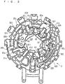
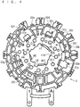
- Figs. 3 and 4 are a front view and a rear view of the insulator 3 for an armature, respectively.
- the front surface of the insulator 3 for an armature shown in the front view is the surface visible in Fig. 1 .
- Figs. 5 and 6 are perspective views of the insulator 3 for an armature, wherein Fig. 5 mainly shows the front surface of the insulator 3 for an armature and Fig. 6 mainly shows the rear surface of the insulator 3 for an armature.
- the three conditions are (i) penetration of the holes H1 to H12 penetrated by the pins Puas, Puae, Pwas, Pwae, Pvbs, Pvbe, Pubs, Pube, Pwbs, Pwbe, Pvas, and Pvae, (ii) an opening around the protrusion 31a that prevents the jumper line Pxv from being disengaged from the guide portion 32B, and (iii) openings around the protrusions 31j and 31k that prevent the jumper line Pxu from being disengaged from the guide portion 32A.
- Figs. 7 and 8 are a front view and a perspective view of the insulator 6, respectively.
- a pin 7 attached to the insulator 6 is also shown.
- the pin 7 is employed for the abovementioned pins Puas, Puae, Pwas, Pwae, Pvbs, Pvbe, Pubs, Pube, Pwbs, Pwbe, Pvas, and Pvae.
- the illustrated insulator 6 can be applied as an object around which one of the coils Lu1 to Lu4, Lv1 to Lv4, Lw1 to Lw4 is wound.
- the insulator 6 covers the tooth (for example, the tooth Tu1), and the coil (for example, the coil Lu1) is wound around the insulator 6.
- the insulator 6 has 607 positioned on the outer peripheral side with respect to each tooth, a plate 608 positioned on the inner peripheral side with respect to each tooth, and a cylinder 601 around which a wire is wound between the plates 607 and 608.
- the cylinder 601 has an inner peripheral surface 602 on its inner side. The tooth is inserted into the inner peripheral surface 602.
- the plate 608 is provided with protrusions 603, 604, and 606 that protrude in the axial direction J when the insulator 6 is provided to the armature.
- a hole 605 is formed in the protrusion 606, and the pin 7 is inserted in the hole 605.
- the protrusions 603 and 604 have a function to fix a wire that connects coils (for example, coils Lu1 and Lu2) forming a coil pair (for example, Lua) to each other while allowing the wire to be wound around the protrusions 603 and 604.
- protrusions 61 and 62 protruding in the direction in which the protrusions 603, 604, and 606 protrude are provided on the plate 607.
- the protrusions 61 and 62 are on the outer peripheral side of the insulator 6 and fix the outer periphery of the insulator 3 for an armature so that the insulator 3 for an armature is fixed to the teeth Tu1 to Tu4, Tv1 to Tv4, and Tw1 to Tw4 in the radial direction via the insulator 6. Due to such fixation, even if an external force is applied to the insulator 3 for an armature, an influence of the external force on the pin is reduced and the effect of preventing the connection between the coils from being impaired is enhanced.
- Fig. 9 is an enlarged perspective view showing a part (an area indicated by a virtual sphere C) in Fig. 8 .
- the protrusion 61 is provided with a groove 63 which opens toward the protrusion 62 and extends in the radial direction.
- the protrusion 62 is similarly provided with a groove 64 which opens toward the protrusion 61 and extends in the radial direction (see Fig. 7 ).
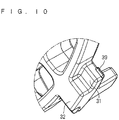
- Fig. 10 is an enlarged perspective view showing a part (an area indicated by a virtual sphere B) in Fig. 5 .
- the base 31 At the outer periphery of the insulator 3 for an armature, the base 31 locally protrudes to the outer periphery, and a protrusion 39 protruding in the circumferential direction is provided on the circumferential end as an engagement part.
- the base 31 locally protruding toward the outer periphery is provided with a protrusion protruding in the circumferential direction on the circumferential end opposite to the protrusion 39.
- the insulator 3 for an armature is fitted to the insulator 6 by the engagement between the protrusion and the groove 63 and the engagement between the protrusion 39 and the groove 64.
- Such engagement prevents the insulator 3 for an armature from separating from the insulator 6, and furthermore from the teeth Tu1 to Tu4, Tv1 to Tv4, and Tw1 to Tw4. That is, the insulator 3 for an armature is fixed in the axial direction J with respect to the coils Lu1 to Lu4, Lv1 to Lv4, and Lw1 to Lw4. Due to such fixation, even if an external force is applied to the insulator 3 for an armature, an influence of the external force on the pin is further reduced and the effect of preventing the connection between the coils from being impaired is further enhanced.
- the present embodiment describes a mode of connection between a power supply line and a wire extending from a coil at a power supply pin.
- Fig. 11 is a schematic diagram showing a mode for connecting a wire 5 and a power supply line 9 to the pin 7 serving as a power supply pin. Note that insulation coatings of the wire 5 and the power supply line 9 are peeled off at a portion adjacent to the pin 7.
- the pin 7 indicates the pin Pvas
- the wire 5 indicates an opposite end of the wire constituting the coil Lv1 from the coil Lv2
- the power supply line 9 indicates the power supply line Cv.
- the pin 7 indicates the pin Puae
- the wire 5 indicates an opposite end of the wire constituting the coil Lu2 from the coil Lu1
- the power supply line 9 indicates the power supply line Cu.
- the pin 7 indicates the pin Pwas
- the wire 5 indicates an opposite end of the wire constituting the coil Lw1 from the coil Lw2
- the power supply line 9 indicates the power supply line Cw.
- a wire having a larger cross-sectional area than a jumper line is used for the power supply line 9 (when a strand wire is used, a strand wire having a larger sum of cross-sectional areas is used). Therefore, winding the power supply line 9 around the pin 7 is not as easy as winding the jumper line around the pin 7.
- one end of the power supply line 9 is disposed along the pin 7 around which the wire 5 is wound, and the one end and the wire 5 are bound to the pin 7 using another wire 8.
- one end of the power supply line 9 and one end of the coil are targets to be bound to the pin 7 with the wire 8.
- Such binding makes it easy to fix the positional relationship with the coil. After such binding, the binding position is soldered.
- the power supply lines Cu, Cv, and Cw are laid on the side opposite to the coils Lv1, Lu2, and Lw2 with respect to the insulator 3 for an armature. Therefore, the insulator 3 for an armature is interposed between the binding positions and the coils in the axial direction J.
Landscapes
- Engineering & Computer Science (AREA)
- Power Engineering (AREA)
- Insulation, Fastening Of Motor, Generator Windings (AREA)
- Windings For Motors And Generators (AREA)
- Motor Or Generator Frames (AREA)
Abstract
Description
- The present invention relates to an insulator used for an armature.
- For example, as disclosed in the following Patent Document 1, there is a technique in which, in an armature provided with a plurality of armature windings (hereinafter also referred to as "coils") which are annularly arranged, pins are correspondingly provided for the coils. This configuration is provided because an end of one of a pair of coils arranged adjacent to each other and an end of the other coil are connected to each other. In Patent Document 1, such a connection is achieved by winding a pair of coils with a continuous wire.
-
Fig. 12 is a connection diagram which shows connection of three-phase coils in a 12-pole armature and which is disclosed in, for example, Patent Document 1. InFig. 12 , a coil pair Lua has coils Lu1 and Lu2 connected in series with each other, and the coils Lu1 and Lu2 are disposed adjacent to each other in the armature. Similarly, a coil pair Lub has coils Lu3 and Lu4, a coil pair Lva has coils Lv1 and Lv2, a coil pair Lvb has coils Lv3 and Lv4, a coil pair Lwa has coils Lw1 and Lw2, and a coil pair Lwb has coils Lw3 and Lw4. - The connection of a pair of coils inside these coil pairs is achieved by a continuous wire as described above. However, a connection between the coil pairs (a so-called "jumper line") needs to be interposed by pins. This is because the coil pair Lua and the coil pair Lub which are connected in series are arranged apart from each other by 180 degrees. The same applies to a jumper line between the coil pairs Lva and Lvb and a jumper line between the coil pairs Lwa and Lwb.
- In order to achieve such a connection between the coil pairs, Patent Document 1 uses a printed circuit board. The printed circuit board is provided with lands to which the pins connected to the ends of the coils are connected, and the lands are connected to each other with a wiring pattern on the printed circuit board. In this way, in the related art, the jumper line is achieved by the pins and the wiring pattern on the printed circuit board.
-
- Patent Document 1: Japanese Patent Application Laid-Open No.
2016-27781 - Patent Document 2:
Japanese Patent Application Laid-Open No. 2004-153973 - Patent Document 3: Japanese Patent Application Laid-Open No.
2008-148533 - However, solder necessary for electrically connecting the lands and the pins is also required to have mechanical strength to fix the printed circuit board to the pins. In other words, if the solder is damaged by an external force applied between the printed circuit board and the pins, the electrical connection may also be impaired due to such damage.
- It is therefore an object of the present invention to provide a technique for arranging a jumper line without increasing an axial dimension of the armature and without using a printed circuit board.
- An insulator (3) for an armature (100) in which a plurality of coils (Lu1 to Lu4, Lv1 to Lv4, Lw1 to Lw4) are annularly arranged and one ends of the coils are connected to pins which respectively correspond to the coils, the insulator (3) being an insulator which is provided so as to align with the coils in an axial direction (J) parallel to an axis (J0) of the armature and which guides three or more jumper lines (Pxu, Pxv, Pxw, Pn) that connect the coils with each other in a circumferential direction with respect to the axis.
- According to a first aspect of the present invention, the insulator has a plurality of holes (HI to H12) that are penetrated by the pins in the axial direction, and a plurality of first guide portions (32F, 32A, 32C; 32F, 32B, 32C) that guide at least three (Pn, Pxu, Pxw; Pn, Pxv, Pxw) of the jumper lines in the circumferential direction with respect to the axis at different positions in a radial direction around the axis.
- According to a second aspect of the present invention, the insulator for an armature according to the first aspect is interposed between the coils and connection portions between the jumper lines and the pins in the axial direction.
- According to a third aspect of the present invention, in the insulator for an armature according to the second aspect, at least one of the first guide portions has at least one protrusion (31j, 31k, 32a to 32f; 31a, 32a to 32f, 32i, 32j) protruding toward an outer periphery along the radial direction.
- According to a fourth aspect of the present invention, in the insulator for an armature according to any one of the first to third aspects, at least one of the pins functions as a power supply pin to which one end of a power supply line (Cu, Cw) is connected together with the one end of one of the coils. The insulator for an armature further includes at least one second guide portion (32D, 32E) for guiding the power supply line in the circumferential direction.
- According to a fifth aspect of the present invention, in the insulator for an armature according to the fourth aspect, the second guide portion has at least one protrusion (32g, 32h) protruding toward the outer periphery along the radial direction.
- According to a sixth aspect of the present invention, in the insulator for an armature according to the fourth or fifth aspect, the one end of the power supply line and the one end of one of the coils are targets to be bound to the power supply pin with another wire, at the power supply pin. The insulator for an armature is interposed between the binding position and the coil in the axial direction.
- According to a seventh aspect of the present invention, in the insulator for an armature according to any one of the first to sixth aspects, one of the coils is wound around a second insulator (6). The insulator for an armature further includes an engagement part (39) to be engaged with the second insulator. The insulator for an armature is fixed to the second insulator in the axial direction by engagement between the second insulator and the engagement part in the axial direction.
- The insulator for an armature according to the first aspect of the present invention eliminates a need to use a printed circuit board for connection, and guides jumper lines without an increase in an axial dimension. Moreover, even if an external force is applied to the insulator for an armature, the connection between the coils is prevented from being impaired.
- The insulator for an armature according to the second aspect of the present invention increases an insulation distance from the coils in many areas of the jumper lines.
- The insulator for an armature according to the third aspect of the present invention inhibits the jumper lines from moving away from the coils.
- The insulator for an armature according to the fourth aspect of the present invention eliminates a need to use a printed circuit board for connection, and guides the power supply line without an increase in an axial dimension.
- The insulator for an armature according to the fifth aspect of the present invention inhibits the power supply line from moving away from the coils.
- The insulator for an armature according to the sixth aspect of the present invention makes it easy to connect one end of the power supply line and one end of the coil.
- The insulator for an armature according to the seventh aspect of the present invention is highly effective in preventing the connection between the coils from being impaired even if an external force is applied to the insulator for an armature.
- The objects, features, aspects, and advantages of the present invention will become more apparent from the following detailed description and the accompanying drawings.
-
- [
Fig. 1 ] A plan view showing an armature employing an insulator for an armature according to a first embodiment. - [
Fig. 2 ] A plan view showing an armature from which the insulator for an armature is removed. - [
Fig. 3 ] A front view of the insulator for an armature. - [
Fig. 4 ] A rear view of the insulator for an armature. - [
Fig. 5 ] A perspective view of the insulator for an armature. - [
Fig. 6 ] A perspective view of the insulator for an armature. - [
Fig. 7 ] A front view of an insulator. - [
Fig. 8 ] A perspective view of the insulator. - [
Fig. 9 ] An enlarged perspective view of a part ofFig. 8 . - [
Fig. 10 ] An enlarged perspective view of a part ofFig. 5 . - [
Fig. 11 ] A schematic diagram showing a mode for connecting a wire and a power supply line to a pin. - [
Fig. 12 ] A connection diagram showing connection of three-phase coils. -
Fig. 1 is a plan view showing anarmature 100 employing aninsulator 3 for an armature according to the first embodiment, as viewed along an axial direction J parallel to an axis J0 of the armature. Thearmature 100 has aninner edge 10 around the axis J0. - A plurality of coils Lu1 to Lu4, Lv1 to Lv4, and Lw1 to Lw4 are annularly arranged. These coils are concentratedly wound around teeth Tu1 to Tu4, Tv1 to Tv4, and Tw1 to Tw4, respectively. The coils Lu1, Lu2, Lw1, Lw2, Lv3, Lv4, Lu3, Lu4, Lw3, Lw4, Lv1, and Lv2 are arranged counterclockwise in this order. Note that, in
Fig. 1 , the wire constituting each coil is schematically shown as a unit. - These twelve coils are divided into six sets of coil pairs, each of which consists of a pair of coils adjacent to each other annularly. More specifically, the coils Lu1 and Lu2 form a coil pair Lua, the coils Lw1 and Lw2 form a coil pair Lwa, the coils Lv3 and Lv4 form a coil pair Lvb, the coils Lu3 and Lu4 form a coil pair Lub, the coils Lw3 and Lw4 form a coil pair Lwb, and the coils Lv1 and Lv2 form a coil pair Lva (see also
Fig. 12 ). - These coils are connected in the manner shown in the connection diagram in
Fig. 12 . InFig. 12 , symbols "s" and "e" attached to each of the coil pairs respectively indicate a winding-start-side end and a winding-end-side end of the wire continuously forming each coil pair. - The coil pairs Lua and Lub are connected to each other such that the winding-start-side ends of the wires constituting the respective coil pairs are connected to each other at a connection point Xu. That is, the coils Lu1 and Lu3 are connected at the connection point Xu. As a result, the coils Lu2, Lu1, Lu3, and Lu4 are connected in series in this order. The coil pairs Lva and Lvb are connected to each other such that the winding-end-side ends of the wires constituting the respective coil pairs are connected to each other at a connection point Xv. That is, the coils Lv2 and Lv4 are connected at the connection point Xv. As a result, the coils Lv1, Lv2, Lv4, and Lv3 are connected in series in this order. The coil pairs Lwa and Lwb are connected to each other such that the winding-end-side ends of the wires constituting the respective coil pairs are connected to each other at a connection point Xw. That is, the coils Lw2 and Lw4 are connected at the connection point Xw. As a result, the coils Lw1, Lw2, Lw4, and Lw3 are connected in series in this order.
- The winding-end-side end of the wire constituting the coil pair Lub, the winding-start-side end of the wire constituting the coil pair Lvb, and the winding-start-side end of the wire constituting the coil pair Lwb are connected at a neutral point N. That is, the coils Lu4, Lv3, and Lw3 are connected at the neutral point N. The connection points Xu, Xv, and Xw and the neutral point N in the connection diagram are achieved by jumper lines Pxu, Pxv, and Pxw in the actual armature, as shown in
Fig. 1 . - When a U-phase current is supplied to the winding-end-side end of the wire constituting the coil pair Lua, a V-phase current is supplied to the winding-start-side end of the wire constituting the coil pair Lva, and a W-phase current is supplied to the winding-start-side end of the wire constituting the coil pair Lwa, the teeth Tu1 to Tu4, Tv1 to Tv4, and Tw1 to Tw4 generate a rotating magnetic field directed toward the outer circumferential side of these teeth (outwardly along the radial direction around the axis J0) (see Patent Document 1). That is, the coils Lu1 to Lu4, Lv1 to Lv4, and Lw1 to Lw4 constitute an armature used for an outer rotor motor.
- The
insulator 3 for an armature is provided so as to align with the coils Lu1 to Lu4, Lv1 to Lv4, and Lw1 to Lw4 in the axial direction J. With reference toFig. 1 , theinsulator 3 for an armature is provided on the front side of the paper to the coils Lu1 to Lu4, Lv1 to Lv4, and Lw1 to Lw4. -
Fig. 2 is a plan view showing a state where theinsulator 3 for an armature is removed from the armature shown inFig. 1 . It is to be noted thatFig. 2 also shows lines indicating bent parts and chamfered parts which are not shown inFig. 1 for avoiding complexity. In the coils Lu1 to Lu4, Lv1 to Lv4 and Lw1 to Lw4, the portions where the outer shapes are bent are indicated by double lines, and the double lines do not represent wires. - Pins Puas, Puae, Pwas, Pwae, Pvbs, Pvbe, Pubs, Pube, Pwbs, Pwbe, Pvas, and Pvae are connected to the ends of corresponding coils Lu1, Lu2, Lw1, Lw2, Lv3, Lv4, Lu3, Lu4, Lw3, Lw4, Lv1, and Lv2. More specifically, the winding-start-side end of the wire constituting the coil pair Lua is connected to the pin Puas, the winding-end-side end of the wire constituting the coil pair Lua is connected to the pin Puae, the winding-start-side end of the wire constituting the coil pair Lub is connected to the pin Pubs, the winding-end-side end of the wire constituting the coil pair Lub is connected to the pin Pube, the winding-start-side end of the wire constituting the coil pair Lva is connected to the pin Pvas, the winding-end-side end of the wire constituting the coil pair Lva is connected to the pin Pvae, the winding-start-side end of the wire constituting the coil pair Lvb is connected to the pin Pvbs, the winding-end-side end of the wire constituting the coil pair Lvb is connected to the pin Pvbe, the winding-start-side end of the wire constituting the coil pair Lwa is connected to the pin Pwas, the winding-end-side end of the wire constituting the coil pair Lwa is connected to the pin Pwae, the winding-start-side end of the wire constituting the coil pair Lwb is connected to the pin Pwbs, and the winding-end-side end of the wire constituting the coil pair Lwb is connected to the pin Pwbe.
- The wires and the pins are specifically connected by soldering. Note that, in order to make it easy to secure electrical conduction, it is desirable that a composition of the pin around which the wire is wound is soldered.
- The description will be continued, returning back to
Fig. 1 . Theinsulator 3 for an armature has a plurality of holes H1 to H12 which are respectively penetrated by the pins Puas, Puae, Pwas, Pwae, Pvbs, Pvbe, Pubs, Pube, Pwbs, Pwbe, Pvas, and Pvae in the axial direction J. - In order to achieve the connection point Xu with the jumper line Pxu, the jumper line Pxu is laid between the holes H2 and H8 which are penetrated by the pins Puas and Pubs, respectively. In order to achieve the connection point Xv with the jumper line Pxv, the jumper line Pxv is laid between the holes H1 and H7 which are penetrated by the pins Pvae and Pvbe, respectively. In order to achieve the connection point Xw with the jumper line Pxw, the jumper line Pxw is laid between the holes H5 and H11 which are penetrated by the pins Pwae and Pwbe pass, respectively. In order to achieve the neutral point N with the jumper line Xn, the jumper line Pn is laid between the holes H9, H6 and H10 which are penetrated by the pins Pube, Pvbs and Pwbs, respectively.
- At least three of these jumper lines Pn, Pxu, Pxv, and Pxw are guided in the circumferential direction at different positions in the radial direction around the axis. More specifically, the
insulator 3 for an armature includes aguide portion 32A for guiding the jumper line Pxu, aguide portion 32B for guiding the jumper line Pxv, aguide portion 32C for guiding the jumper line Pxw, and aguide portion 32F for guiding the jumper line Pn. - The
insulator 3 for an armature has abase 31 and a protrudingportion 32 that protrudes from the base 31 toward the front side of the paper (that is, toward the side opposite to the coils Lu1 to Lu4, Lv1 to Lv4, and Lw1 to Lw4 in the axial direction J). InFig. 1 , thebase 31 is shown by coarse dots, and the protrudingportion 32 is shown by two types of fine dots. The part shown by finer dots of the two types of fine dots indicates an area (described in detail later) of the protrudingportion 32 protruding further toward the front side of the paper. - In the jumper lines Pn, Pxu, Pxv, and Pxw, portions which are laid on the side of coils Lu1 to Lu4, Lv1 to Lv4, and Lw1 to Lw4 with respect to the
insulator 3 for an armature are shown by broken lines, regardless of whether or not they are hidden lines. - Many portions of the jumper lines Pn, Pxu, Pxv, and Pxw are laid on the side opposite to the coils Lu1 to Lu4, Lv1 to Lv4, and Lw1 to Lw4 with respect to the
insulator 3 for an armature. Therefore, connection portions between the jumper line Pxu and the pins Puas and Pubs, connection portions between the jumper line Pxv and the pins Pvae and Pvbe, and connection portions between the jumper line Pxw and the pins Pwae and Pwbe are all located on the side opposite to the coils Lu1 to Lu4, Lv1 to Lv4, and Lw1 to Lw4 with respect to theinsulator 3 for an armature. In other words, theinsulator 3 for an armature is interposed between these connection portions and the coils Lu1 to Lu4, Lv1 to Lv4 and Lw1 to Lw4 in the axial direction J. Such interposition is desirable from the viewpoint of increasing an insulation distance from the coils Lu1 to Lu4, Lv1 to Lv4, and Lw1 to Lw4 in many portions of the jumper lines Pn, Pxu, Pxv, and Pxw. - The
guide portion 32A has the protrudingportion 32 protruding from the base 31 on a hole H4 side with respect to the hole H5. By being guided by this portion, the jumper line Pxu which extends from the hole H2 through an area between the holes H4 and H5 toward the outer periphery and then is bent counterclockwise in the circumferential direction. - The
guide portion 32A has the protrudingportion 32 protruding from the base 31 on a hole H7 side with respect to the hole H8. By being guided by this portion, the jumper line Pxu which extends from the hole H8 toward the outer periphery and then is bent clockwise in the circumferential direction. This portion also has aprotrusion 32j protruding toward the outer periphery. - As shown in
Fig. 1 , theguide portion 32A may have the protrudingportion 32 protruding from the base 31 on the outer peripheral side with respect to the holes H6 and H7. This portion guides the jumper line Pxu to the outer peripheral side with respect to the holes H5 to H8. However, in order to lay the jumper lines Pxw and Pxv on the base 31 side with respect to the protrudingportion 32, there are regions where the protrudingportion 32 is not provided (regions whereprotrusions 31k and 31j protruding toward the outer periphery is exposed in the base 31) on the outer peripheral side between the holes H5 and H6 and on the outer peripheral side between the holes H7 and H8. - In
Fig. 1 , the jumper line Pxu is laid on the side of the coils Lu3 and Lv3 with respect to theprotrusions 31j and 31k. Theprotrusions 31j and 31k inhibit the jumper line Pxu from moving away from the coils Lu3 and Lv3. Such inhibition is desirable from the viewpoint of preventing the jumper line Pxu from being disengaged from theguide portion 32A. - In addition, the
protrusion 32j is desirable from the viewpoint of preventing the jumper line Pxv from being disengaged from aguide portion 32B described later. - The
guide portion 32B has the protrudingportion 32 protruding from the base 31 on a hole H12 side with respect to the hole H11. By being guided by this portion, the jumper line Pxv extends from the inner peripheral side toward the outer peripheral side between the holes H11 and H12 and then is bent clockwise in the circumferential direction. - The
guide portion 32B has the protrudingportion 32 protruding from the base 31 on the outer peripheral side with respect to the holes H8 to H11. This portion guides the jumper line Pxv to the outer peripheral side with respect to the holes H8 to H11. However, in order to lay the jumper lines Pxu and Pxw on the base 31 side with respect to the protrudingportion 32, there are regions where the protrudingportion 32 is not provided on the outer peripheral side with respect to the hole H8 and on the outer peripheral side between the holes H10 and H11 (regions where aprotrusion 31a protruding toward the outer periphery is exposed in the base 31). - In
Fig. 1 , the jumper line Pxv is laid on the coil Lw4 side with respect to theprotrusion 31a. Theprotrusion 31a inhibits the jumper line Pxv from moving away from the coil Lw4. Such inhibition is desirable from the viewpoint of preventing the jumper line Pxv from being disengaged from theguide portion 32B. - Similar inhibition is achieved by a
protrusion 32i which is a part of the protrudingportion 32 and which protrudes toward the front side of the paper and toward the outer periphery on the outer peripheral side with respect to the hole H9. Theprotrusion 32i can also be regarded as theguide portion 32B. The jumper line Pxv is laid on the coil Lu4 side with respect to theprotrusion 32i and the movement of the jumper line Pxv in a direction away from the coil Lu4 is inhibited. - The
guide portion 32B has aprotrusion 32a protruding toward the outer periphery on the outer peripheral side between the holes H10 and H11. Theprotrusion 32a is desirable from the viewpoint of preventing the jumper line Pxw from being disengaged from aguide portion 32C described later. - The
guide portion 32C has the protrudingportion 32 protruding from the base 31 on the outer peripheral side with respect to the holes H6 to H10 and on the outer peripheral side with respect to theguide portions - The
guide portion 32C has aprotrusion 32b formed near the outer peripheral side with respect to the hole H9 so as to protrude toward the outer periphery, aprotrusion 32c formed near the outer peripheral side with respect to the hole H8 so as to protrude toward the outer periphery, aprotrusion 32d formed near the outer peripheral side with respect to the hole H7 so as to protrude toward the outer periphery, and aprotrusion 32e formed near the outer peripheral side with respect to the hole H6 so as to protrude toward the outer periphery. - The jumper line Pxw is laid on the side of the coils Lw3 and Lu4 with respect to the
protrusion 32b, on the side of the coils Lu4 and Lu3 with respect to theprotrusion 32c, on the side of the coils Lu3 and Lv4 with respect to theprotrusion 32d, and on the side of the coils Lv3 and Lv4 with respect to theprotrusion 32e, respectively. Theprotrusions 32b to 32e inhibit the jumper line Pxw from moving away from the coils Lw3, Lu4, Lu3, Lv4, and Lv3. Such inhibition is desirable from the viewpoint of preventing the jumper line Pxw from being disengaged from theguide portion 32C. - Similar inhibition is achieved by a
protrusion 32f which is a part of the protrudingportion 32 and which protrudes toward the front side of the paper and in the circumferential direction on the outer peripheral side with respect to the hole H6. Theprotrusion 32f can also be regarded as theguide portion 32C. The jumper line Pxw is laid on the coil Lv3 side with respect to theprotrusion 32f and the movement of the jumper line Pxw in a direction away from the coil Lv3 is inhibited. - The
protrusion 32f also has a function to switch the laying direction of (a function to bend) the jumper line Pxw between the radial direction and the circumferential direction in a region between the hole H5 and theprotrusion 32e. - The
guide portion 32F has the protrudingportion 32 protruding from the base 31 on the inner peripheral side with respect to the holes H7 to H9. This portion guides the jumper line Pn on the coils Lu3, Lv3, and Lu4 side with respect to the base 31 on the inner peripheral side with respect to the holes H7 to H9. - From the above, the jumper lines Pn, Pxu, and Pxw are guided in the circumferential direction at radially different positions by the
guide portions - Further, the jumper lines Pn, Pxv, and Pxw are guided in the circumferential direction at radially different positions by the
guide portions - The
guide portions insulator 3 for an armature is used in place of a printed circuit board, the jumper lines are guided without an increase in the axial dimension. Moreover, the holes H1 to H12 are not the targets to be soldered as the lands on the printed circuit board are, and thus, even if an external force is applied, the connection between the coils is not impaired. Also, the amount of solder required for soldering is smaller than that in the case of using a printed circuit board. - A power supply line Cu is connected to the pin Puae for supplying a U-phase current. A power supply line Cv is connected to the pin Pvas for supplying a V-phase current. A power supply line Cw is connected to the pin Pwas for supplying a W-phase current. That is, the pins Puae, Pvas, and Pwas function as power supply pins to which not only the ends of the coils Lu2, Lv1, and Lw1 but also one ends of the power supply lines Cu, Cv, and Cw are connected. An example of connection at the power supply pin will be described in detail in another embodiment.
- A connector 4 introduces the power supply lines Cu, Cv, and Cw from outside the
insulator 3 for an armature. Pins Puae, Pvas, and Pwas pass through the holes H3, H12, and H4, respectively. Therefore, in theinsulator 3 for an armature, the power supply line Cu is laid from the connector 4 to the hole H3, the power supply line Cv is laid from the connector 4 to the hole H12, and the power supply line Cu is laid from the connector 4 to the hole H4. The power supply lines Cu and Cw are guided in the circumferential direction by theguide portions - The
guide portion 32D has the protrudingportion 32 protruding from the base 31 on the outer peripheral side with respect to the holes H1 to H3. This portion guides the power supply line Cu to the outer peripheral side with respect to the holes H1 to H3. - The
guide portion 32D also has the protrudingportion 32 protruding from the base 31 on the H2 side with respect to the hole H3. The power supply line Cu which extends toward the outer peripheral side as viewed from the hole H3 bends in the circumferential direction at this portion. - The
guide portion 32D has aprotrusion 32h protruding toward the front side of paper and toward the outer peripheral side, near the outer peripheral side with respect to the hole H2. The power supply line Cu is laid on the coil Lu1 side with respect to theprotrusion 32h. Theprotrusion 32h inhibits the power supply line Cu from moving away from the coil Lu1. Such inhibition is desirable from the viewpoint of preventing the power supply line Cu from being disengaged from theguide portion 32D. - The
guide portion 32E has the protrudingportion 32 protruding from the base 31 on the outer peripheral side with respect to the holes H1 to H4 and on the outer peripheral side with respect to theguide portion 32D. This portion guides the power supply line Cw to the outer peripheral side with respect to the holes H1 to H4. - The
guide portion 32E also has the protrudingportion 32 protruding from thebase 31 near the outer peripheral side with respect to the hole H4. The power supply line Cw which extends toward the outer peripheral side as viewed from the hole H4 bends in the circumferential direction at this portion. - The
guide portion 32E has aprotrusion 32g protruding toward the front side of the paper and toward the outer peripheral side near the outer peripheral side with respect to the hole H4. The power supply line Cw is laid on the coil Lw1 side with respect to theprotrusion 32g. Theprotrusion 32g inhibits the power supply line Cw from moving away from the coil Lw1. Such inhibition is desirable from the viewpoint of preventing the power supply line Cw from being disengaged from theguide portion 32E. - From the above, the power supply lines Cu and Cw are guided in the circumferential direction at radially different positions by the
guide portions - Therefore, when the
insulator 3 for an armature is used in place of a printed circuit board, the power supply lines Cu and Cw are also guided in the circumferential direction without an increase in the axial dimension, as in the jumper lines Pn, Pxu, Pxv, and Pxw. - As described above, the
guide portion 32A is capable of functioning to guide the jumper line Pxu in the circumferential direction, and to assist the guiding of the jumper line Pxv in the circumferential direction by theguide portion 32B due to theprotrusion 32j of theguide portion 32A. Theguide portion 32B is capable of functioning to guide the jumper line Pxv in the circumferential direction, and to assist the guiding of the jumper line Pxw in the circumferential direction by theguide portion 32C due to theprotrusion 32a of theguide portion 32B. - Similar to the combined functions described above, the
guide portion 32D may inhibit the jumper line Pxu from moving away from the coils Lu2 and Lw1 on the inner peripheral side with respect to the holes H3 and H4. The circumferential end of theguide portion 32E may guide the power supply line Cu from the connector 4 to theguide portion 32D on the outer peripheral side with respect to the hole H2. -
Figs. 3 and4 are a front view and a rear view of theinsulator 3 for an armature, respectively. The front surface of theinsulator 3 for an armature shown in the front view is the surface visible inFig. 1 . -
Figs. 5 and6 are perspective views of theinsulator 3 for an armature, whereinFig. 5 mainly shows the front surface of theinsulator 3 for an armature andFig. 6 mainly shows the rear surface of theinsulator 3 for an armature. - If the
base 31 of theinsulator 3 for an armature satisfies the following three conditions, the abovementioned operations and effects are obtained, even if all of the ends (the parts visible inFig. 1 ) of the coils Lu1 to Lu4, Lv1 to Lv4, and Lw1 and Lw4 in the axial direction J are covered. The three conditions are (i) penetration of the holes H1 to H12 penetrated by the pins Puas, Puae, Pwas, Pwae, Pvbs, Pvbe, Pubs, Pube, Pwbs, Pwbe, Pvas, and Pvae, (ii) an opening around theprotrusion 31a that prevents the jumper line Pxv from being disengaged from theguide portion 32B, and (iii) openings around theprotrusions 31j and 31k that prevent the jumper line Pxu from being disengaged from theguide portion 32A. - Note that, from the viewpoint of dissipating heat from the coils Lu1 to Lu4, Lv1 to Lv4, and Lw1 to Lw4, through-holes are formed, as appropriate, as shown in
Figs. 1 to 3 and6 . - In the present embodiment, the shape of an
insulator 6 which is another insulator interposed between coils and teeth will be described. -
Figs. 7 and8 are a front view and a perspective view of theinsulator 6, respectively. InFig. 8 , apin 7 attached to theinsulator 6 is also shown. Thepin 7 is employed for the abovementioned pins Puas, Puae, Pwas, Pwae, Pvbs, Pvbe, Pubs, Pube, Pwbs, Pwbe, Pvas, and Pvae. Likewise, the illustratedinsulator 6 can be applied as an object around which one of the coils Lu1 to Lu4, Lv1 to Lv4, Lw1 to Lw4 is wound. - Since the basic configuration of the
insulator 6 is publicly known as disclosed in Patent Document 1, for example, it will be briefly described. Theinsulator 6 covers the tooth (for example, the tooth Tu1), and the coil (for example, the coil Lu1) is wound around theinsulator 6. Theinsulator 6 has 607 positioned on the outer peripheral side with respect to each tooth, aplate 608 positioned on the inner peripheral side with respect to each tooth, and acylinder 601 around which a wire is wound between theplates cylinder 601 has an innerperipheral surface 602 on its inner side. The tooth is inserted into the innerperipheral surface 602. - The
plate 608 is provided withprotrusions insulator 6 is provided to the armature. Ahole 605 is formed in theprotrusion 606, and thepin 7 is inserted in thehole 605. Theprotrusions protrusions - Although not described in detail in Patent Document 1,
protrusions protrusions plate 607. Theprotrusions insulator 6 and fix the outer periphery of theinsulator 3 for an armature so that theinsulator 3 for an armature is fixed to the teeth Tu1 to Tu4, Tv1 to Tv4, and Tw1 to Tw4 in the radial direction via theinsulator 6. Due to such fixation, even if an external force is applied to theinsulator 3 for an armature, an influence of the external force on the pin is reduced and the effect of preventing the connection between the coils from being impaired is enhanced. -
Fig. 9 is an enlarged perspective view showing a part (an area indicated by a virtual sphere C) inFig. 8 . Theprotrusion 61 is provided with agroove 63 which opens toward theprotrusion 62 and extends in the radial direction. Although not shown inFig. 9 , theprotrusion 62 is similarly provided with agroove 64 which opens toward theprotrusion 61 and extends in the radial direction (seeFig. 7 ). -
Fig. 10 is an enlarged perspective view showing a part (an area indicated by a virtual sphere B) inFig. 5 . At the outer periphery of theinsulator 3 for an armature, thebase 31 locally protrudes to the outer periphery, and aprotrusion 39 protruding in the circumferential direction is provided on the circumferential end as an engagement part. Although not shown inFig. 10 , thebase 31 locally protruding toward the outer periphery is provided with a protrusion protruding in the circumferential direction on the circumferential end opposite to theprotrusion 39. - The
insulator 3 for an armature is fitted to theinsulator 6 by the engagement between the protrusion and thegroove 63 and the engagement between theprotrusion 39 and thegroove 64. Such engagement prevents theinsulator 3 for an armature from separating from theinsulator 6, and furthermore from the teeth Tu1 to Tu4, Tv1 to Tv4, and Tw1 to Tw4. That is, theinsulator 3 for an armature is fixed in the axial direction J with respect to the coils Lu1 to Lu4, Lv1 to Lv4, and Lw1 to Lw4. Due to such fixation, even if an external force is applied to theinsulator 3 for an armature, an influence of the external force on the pin is further reduced and the effect of preventing the connection between the coils from being impaired is further enhanced. - The present embodiment describes a mode of connection between a power supply line and a wire extending from a coil at a power supply pin.
-
Fig. 11 is a schematic diagram showing a mode for connecting awire 5 and a power supply line 9 to thepin 7 serving as a power supply pin. Note that insulation coatings of thewire 5 and the power supply line 9 are peeled off at a portion adjacent to thepin 7. - With reference to the first embodiment, the
pin 7 indicates the pin Pvas, thewire 5 indicates an opposite end of the wire constituting the coil Lv1 from the coil Lv2, and the power supply line 9 indicates the power supply line Cv. Alternatively, thepin 7 indicates the pin Puae, thewire 5 indicates an opposite end of the wire constituting the coil Lu2 from the coil Lu1, and the power supply line 9 indicates the power supply line Cu. Alternatively, thepin 7 indicates the pin Pwas, thewire 5 indicates an opposite end of the wire constituting the coil Lw1 from the coil Lw2, and the power supply line 9 indicates the power supply line Cw. - Normally, a wire having a larger cross-sectional area than a jumper line is used for the power supply line 9 (when a strand wire is used, a strand wire having a larger sum of cross-sectional areas is used). Therefore, winding the power supply line 9 around the
pin 7 is not as easy as winding the jumper line around thepin 7. In view of this, in the present embodiment, one end of the power supply line 9 is disposed along thepin 7 around which thewire 5 is wound, and the one end and thewire 5 are bound to thepin 7 using anotherwire 8. In other words, at thepin 7, one end of the power supply line 9 and one end of the coil are targets to be bound to thepin 7 with thewire 8. Such binding makes it easy to fix the positional relationship with the coil. After such binding, the binding position is soldered. - As shown in
Fig. 1 , the power supply lines Cu, Cv, and Cw are laid on the side opposite to the coils Lv1, Lu2, and Lw2 with respect to theinsulator 3 for an armature. Therefore, theinsulator 3 for an armature is interposed between the binding positions and the coils in the axial direction J. - While the present invention has been described in detail, the foregoing description is in all aspects illustrative and not restrictive. It is therefore understood that numerous modifications and variations can be conceived of without departing from the scope of the present invention.
Claims (8)
- An insulator (3) for an armature (100) in which a plurality of coils (Lu1 to Lu4, Lv1 to Lv4, Lw1 to Lw4) are annularly arranged and one ends of the coils are connected to pins which respectively correspond to the coils, the insulator (3) being an insulator which is provided so as to align with the coils in an axial direction (J) parallel to an axis (J0) of the armature and which guides three or more jumper lines (Pxu, Pxv, Pxw, Pn) that connect the coils with each other in a circumferential direction with respect to the axis,
the insulator comprising:a plurality of holes (HI to H12) that is penetrated by the pins in the axial direction; anda plurality of first guide portions (32F, 32A, 32C; 32F, 32B, 32C) that guide at least three (Pn, Pxu, Pxw; Pn, Pxv, Pxw) of the jumper lines in the circumferential direction with respect to the axis at different positions in a radial direction around the axis. - The insulator (3) for an armature according to claim 1, wherein the insulator is interposed between the coils and connection portions between the jumper lines and the pins in the axial direction.
- The insulator (3) for an armature according to claim 2, wherein at least one of the first guide portions has at least one protrusion (31j, 31k, 32a to 32f; 31a, 32a to 32f, 32i, 32j) protruding toward an outer periphery along the radial direction.
- The insulator (3) for an armature according to any one of claims 1 to 3,
wherein at least one of the pins functions as a power supply pin to which one end of a power supply line (Cu, Cw) is connected together with the one end of one of the coils, and
the insulator (3) for an armature further comprises at least one second guide portion (32D, 32E) for guiding the power supply line in the circumferential direction. - The insulator (3) for an armature according to claim 4, wherein the second guide portion has at least one protrusion (32g, 32h) protruding toward the outer periphery along the radial direction.
- The insulator (3) for an armature according to claim 4 or 5,
wherein, at the power supply pin, the one end of the power supply line and the one end of one of the coils are targets to be bound to the power supply pin with another wire, and
the insulator (3) is interposed between the binding position and the coil in the axial direction. - The insulator (3) for an armature according to any one of claims 1 to 6,
wherein one of the coils is wound around a second insulator (6),
the insulator for an armature further comprises an engagement part (39) to be engaged with the second insulator, and
the insulator for an armature is fixed to the second insulator in the axial direction by engagement between the second insulator and the engagement part in the axial direction. - An outer rotor motor employing an armature which is constituted by the plurality of coils (Lu1 to Lu4, Lv1 to Lv4, Lw1 to Lw4) annularly arranged on the insulator (3) for an armature according to any one of claims 1 to 7.
Applications Claiming Priority (2)
| Application Number | Priority Date | Filing Date | Title |
|---|---|---|---|
| JP2016212584A JP6296137B1 (en) | 2016-10-31 | 2016-10-31 | Insulator and motor for armature |
| PCT/JP2017/038479 WO2018079587A1 (en) | 2016-10-31 | 2017-10-25 | Insulator for armature, motor |
Publications (3)
| Publication Number | Publication Date |
|---|---|
| EP3534501A1 true EP3534501A1 (en) | 2019-09-04 |
| EP3534501A4 EP3534501A4 (en) | 2020-06-03 |
| EP3534501B1 EP3534501B1 (en) | 2023-11-22 |
Family
ID=61629171
Family Applications (1)
| Application Number | Title | Priority Date | Filing Date |
|---|---|---|---|
| EP17865624.5A Active EP3534501B1 (en) | 2016-10-31 | 2017-10-25 | Insulator for armature, motor |
Country Status (10)
| Country | Link |
|---|---|
| US (1) | US10516313B2 (en) |
| EP (1) | EP3534501B1 (en) |
| JP (1) | JP6296137B1 (en) |
| CN (1) | CN109863667B (en) |
| AU (1) | AU2017351271B2 (en) |
| BR (1) | BR112019007226B1 (en) |
| ES (1) | ES2966667T3 (en) |
| MY (1) | MY175925A (en) |
| SG (1) | SG11201903873XA (en) |
| WO (1) | WO2018079587A1 (en) |
Families Citing this family (2)
| Publication number | Priority date | Publication date | Assignee | Title |
|---|---|---|---|---|
| DE102021133409A1 (en) | 2021-12-16 | 2023-06-22 | Minebea Mitsumi Inc. | Stator for an electric machine |
| JP7741428B1 (en) * | 2024-05-30 | 2025-09-18 | ダイキン工業株式会社 | Molded motor and air conditioner equipped with molded motor |
Family Cites Families (17)
| Publication number | Priority date | Publication date | Assignee | Title |
|---|---|---|---|---|
| JPS5519809A (en) * | 1978-07-28 | 1980-02-12 | Hitachi Ltd | Circuit board |
| JPH07284239A (en) * | 1994-04-11 | 1995-10-27 | Fujitsu General Ltd | Electric motor |
| JP3430839B2 (en) * | 1997-03-03 | 2003-07-28 | 松下電器産業株式会社 | Stator connection structure |
| JP3696080B2 (en) * | 2000-12-05 | 2005-09-14 | 三菱電機株式会社 | Rotating electric machine |
| JP2002247792A (en) * | 2001-02-15 | 2002-08-30 | Hitachi Ltd | Stator for rotating electric machine, wiring processing board for coil, and rotating electric machine |
| JP2004153973A (en) | 2002-11-01 | 2004-05-27 | Tamagawa Seiki Co Ltd | Resolver insulation cap structure |
| DE10318816B4 (en) * | 2003-04-17 | 2007-06-28 | Minebea Co., Ltd. | Stator with wiring structure for stator windings |
| EP2017945A4 (en) * | 2006-06-01 | 2014-10-22 | Panasonic Corp | ENGINE STATOR AND MOTOR MOLD |
| JP4140646B2 (en) * | 2006-10-03 | 2008-08-27 | ダイキン工業株式会社 | Brushless motor stator |
| JP2008148533A (en) | 2006-12-13 | 2008-06-26 | Nidec Shibaura Corp | Motor |
| JP4270307B2 (en) | 2007-06-25 | 2009-05-27 | トヨタ自動車株式会社 | Crossover module |
| US8492948B2 (en) * | 2010-10-21 | 2013-07-23 | Emerson Electric Co. | End caps for stator segments of segmented stator assemblies |
| JP5328969B2 (en) | 2012-03-12 | 2013-10-30 | 日立電線株式会社 | Electric motor and central power distribution member |
| JP5561415B2 (en) * | 2012-03-12 | 2014-07-30 | 日立金属株式会社 | Electric motor and central power distribution member |
| JP5924082B2 (en) | 2012-03-31 | 2016-05-25 | 日本電産株式会社 | Molded motor stator and molded motor using the same |
| JP6248251B2 (en) * | 2013-11-29 | 2017-12-20 | 多摩川精機株式会社 | Outer rotor type rotation sensor signal lead-out structure |
| JP5928642B2 (en) | 2014-07-01 | 2016-06-01 | ダイキン工業株式会社 | Armature, rotating electric machine, cross flow fan, armature tooth pair manufacturing method |
-
2016
- 2016-10-31 JP JP2016212584A patent/JP6296137B1/en active Active
-
2017
- 2017-10-25 AU AU2017351271A patent/AU2017351271B2/en active Active
- 2017-10-25 BR BR112019007226-8A patent/BR112019007226B1/en active IP Right Grant
- 2017-10-25 EP EP17865624.5A patent/EP3534501B1/en active Active
- 2017-10-25 MY MYPI2019002225A patent/MY175925A/en unknown
- 2017-10-25 US US16/345,922 patent/US10516313B2/en active Active
- 2017-10-25 ES ES17865624T patent/ES2966667T3/en active Active
- 2017-10-25 WO PCT/JP2017/038479 patent/WO2018079587A1/en not_active Ceased
- 2017-10-25 CN CN201780065818.3A patent/CN109863667B/en active Active
- 2017-10-25 SG SG11201903873XA patent/SG11201903873XA/en unknown
Also Published As
| Publication number | Publication date |
|---|---|
| ES2966667T3 (en) | 2024-04-23 |
| JP6296137B1 (en) | 2018-03-20 |
| CN109863667A (en) | 2019-06-07 |
| EP3534501A4 (en) | 2020-06-03 |
| BR112019007226A2 (en) | 2019-07-02 |
| CN109863667B (en) | 2020-04-07 |
| US10516313B2 (en) | 2019-12-24 |
| SG11201903873XA (en) | 2019-05-30 |
| US20190296598A1 (en) | 2019-09-26 |
| AU2017351271A1 (en) | 2019-05-23 |
| BR112019007226B1 (en) | 2020-10-27 |
| WO2018079587A1 (en) | 2018-05-03 |
| AU2017351271B2 (en) | 2019-09-19 |
| JP2018074769A (en) | 2018-05-10 |
| EP3534501B1 (en) | 2023-11-22 |
| MY175925A (en) | 2020-07-15 |
Similar Documents
| Publication | Publication Date | Title |
|---|---|---|
| CN100428612C (en) | Interconnecting ring and wire guide for an electric machine stator | |
| KR101606262B1 (en) | Bobbin and rotary electric machine | |
| EP2369722A2 (en) | Stator for rotary electrical machine | |
| US10476336B2 (en) | Stator assembly | |
| US9276446B2 (en) | Active part of an electrical machine having inclined coils in the winding head area | |
| US7262538B2 (en) | Concentrated winding stator coil for an electric rotary machine | |
| US6181046B1 (en) | Dynamo-electric machine with commutator assembly | |
| EP3534501B1 (en) | Insulator for armature, motor | |
| US7808137B2 (en) | Single track layer stator terminal assembly | |
| JP2014128095A (en) | Power line fixing member | |
| JP2005245138A (en) | motor | |
| EP2738917A2 (en) | Power line connecting structure of a stator | |
| US10601285B2 (en) | Wiring board, electric motor, electric apparatus, and air conditioner | |
| CN102545413B (en) | Armature and motor | |
| EP2768121B1 (en) | Lead wire connection structure of rotating electric machine | |
| JP2000217293A (en) | Rotating electric machine | |
| CN106605355A (en) | Stator of rotating electrical machine and rotating electrical machine provided with the stator of the rotating electrical machine | |
| CN210123922U (en) | Motor with a motor stator | |
| JP7076503B2 (en) | Electric motor | |
| KR20250054087A (en) | Rotating electric motor and its manufacturing method | |
| JPH1056765A (en) | Dc brushless motor | |
| JP2005245140A (en) | Motor | |
| JP2015056937A (en) | Connection structure for rotary electric machine unit | |
| JP2020137288A (en) | Rotating machine | |
| JP2014135786A (en) | Stator for rotary electric machine, and rotary electric machine |
Legal Events
| Date | Code | Title | Description |
|---|---|---|---|
| STAA | Information on the status of an ep patent application or granted ep patent |
Free format text: STATUS: THE INTERNATIONAL PUBLICATION HAS BEEN MADE |
|
| PUAI | Public reference made under article 153(3) epc to a published international application that has entered the european phase |
Free format text: ORIGINAL CODE: 0009012 |
|
| STAA | Information on the status of an ep patent application or granted ep patent |
Free format text: STATUS: REQUEST FOR EXAMINATION WAS MADE |
|
| 17P | Request for examination filed |
Effective date: 20190513 |
|
| AK | Designated contracting states |
Kind code of ref document: A1 Designated state(s): AL AT BE BG CH CY CZ DE DK EE ES FI FR GB GR HR HU IE IS IT LI LT LU LV MC MK MT NL NO PL PT RO RS SE SI SK SM TR |
|
| AX | Request for extension of the european patent |
Extension state: BA ME |
|
| DAV | Request for validation of the european patent (deleted) | ||
| DAX | Request for extension of the european patent (deleted) | ||
| A4 | Supplementary search report drawn up and despatched |
Effective date: 20200507 |
|
| RIC1 | Information provided on ipc code assigned before grant |
Ipc: H02K 3/52 20060101AFI20200429BHEP Ipc: H02K 21/22 20060101ALN20200429BHEP |
|
| STAA | Information on the status of an ep patent application or granted ep patent |
Free format text: STATUS: EXAMINATION IS IN PROGRESS |
|
| 17Q | First examination report despatched |
Effective date: 20210719 |
|
| RAP3 | Party data changed (applicant data changed or rights of an application transferred) |
Owner name: DAIKIN INDUSTRIES, LTD. |
|
| REG | Reference to a national code |
Ref country code: DE Ref legal event code: R079 Free format text: PREVIOUS MAIN CLASS: H02K0003340000 Ipc: H02K0003520000 Ref document number: 602017076840 Country of ref document: DE |
|
| GRAP | Despatch of communication of intention to grant a patent |
Free format text: ORIGINAL CODE: EPIDOSNIGR1 |
|
| STAA | Information on the status of an ep patent application or granted ep patent |
Free format text: STATUS: GRANT OF PATENT IS INTENDED |
|
| RIC1 | Information provided on ipc code assigned before grant |
Ipc: H02K 21/22 20060101ALN20230509BHEP Ipc: H02K 3/32 20060101ALI20230509BHEP Ipc: H02K 3/52 20060101AFI20230509BHEP |
|
| INTG | Intention to grant announced |
Effective date: 20230531 |
|
| P01 | Opt-out of the competence of the unified patent court (upc) registered |
Effective date: 20230525 |
|
| GRAS | Grant fee paid |
Free format text: ORIGINAL CODE: EPIDOSNIGR3 |
|
| GRAA | (expected) grant |
Free format text: ORIGINAL CODE: 0009210 |
|
| STAA | Information on the status of an ep patent application or granted ep patent |
Free format text: STATUS: THE PATENT HAS BEEN GRANTED |
|
| AK | Designated contracting states |
Kind code of ref document: B1 Designated state(s): AL AT BE BG CH CY CZ DE DK EE ES FI FR GB GR HR HU IE IS IT LI LT LU LV MC MK MT NL NO PL PT RO RS SE SI SK SM TR |
|
| REG | Reference to a national code |
Ref country code: GB Ref legal event code: FG4D |
|
| REG | Reference to a national code |
Ref country code: CH Ref legal event code: EP Ref country code: DE Ref legal event code: R096 Ref document number: 602017076840 Country of ref document: DE |
|
| REG | Reference to a national code |
Ref country code: IE Ref legal event code: FG4D |
|
| REG | Reference to a national code |
Ref country code: LT Ref legal event code: MG9D |
|
| REG | Reference to a national code |
Ref country code: NL Ref legal event code: MP Effective date: 20231122 |
|
| PG25 | Lapsed in a contracting state [announced via postgrant information from national office to epo] |
Ref country code: GR Free format text: LAPSE BECAUSE OF FAILURE TO SUBMIT A TRANSLATION OF THE DESCRIPTION OR TO PAY THE FEE WITHIN THE PRESCRIBED TIME-LIMIT Effective date: 20240223 |
|
| PG25 | Lapsed in a contracting state [announced via postgrant information from national office to epo] |
Ref country code: IS Free format text: LAPSE BECAUSE OF FAILURE TO SUBMIT A TRANSLATION OF THE DESCRIPTION OR TO PAY THE FEE WITHIN THE PRESCRIBED TIME-LIMIT Effective date: 20240322 |
|
| PG25 | Lapsed in a contracting state [announced via postgrant information from national office to epo] |
Ref country code: LT Free format text: LAPSE BECAUSE OF FAILURE TO SUBMIT A TRANSLATION OF THE DESCRIPTION OR TO PAY THE FEE WITHIN THE PRESCRIBED TIME-LIMIT Effective date: 20231122 |
|
| REG | Reference to a national code |
Ref country code: AT Ref legal event code: MK05 Ref document number: 1634763 Country of ref document: AT Kind code of ref document: T Effective date: 20231122 |
|
| PG25 | Lapsed in a contracting state [announced via postgrant information from national office to epo] |
Ref country code: NL Free format text: LAPSE BECAUSE OF FAILURE TO SUBMIT A TRANSLATION OF THE DESCRIPTION OR TO PAY THE FEE WITHIN THE PRESCRIBED TIME-LIMIT Effective date: 20231122 |
|
| PG25 | Lapsed in a contracting state [announced via postgrant information from national office to epo] |
Ref country code: AT Free format text: LAPSE BECAUSE OF FAILURE TO SUBMIT A TRANSLATION OF THE DESCRIPTION OR TO PAY THE FEE WITHIN THE PRESCRIBED TIME-LIMIT Effective date: 20231122 |
|
| REG | Reference to a national code |
Ref country code: ES Ref legal event code: FG2A Ref document number: 2966667 Country of ref document: ES Kind code of ref document: T3 Effective date: 20240423 |
|
| PG25 | Lapsed in a contracting state [announced via postgrant information from national office to epo] |
Ref country code: NL Free format text: LAPSE BECAUSE OF FAILURE TO SUBMIT A TRANSLATION OF THE DESCRIPTION OR TO PAY THE FEE WITHIN THE PRESCRIBED TIME-LIMIT Effective date: 20231122 Ref country code: LT Free format text: LAPSE BECAUSE OF FAILURE TO SUBMIT A TRANSLATION OF THE DESCRIPTION OR TO PAY THE FEE WITHIN THE PRESCRIBED TIME-LIMIT Effective date: 20231122 Ref country code: IS Free format text: LAPSE BECAUSE OF FAILURE TO SUBMIT A TRANSLATION OF THE DESCRIPTION OR TO PAY THE FEE WITHIN THE PRESCRIBED TIME-LIMIT Effective date: 20240322 Ref country code: GR Free format text: LAPSE BECAUSE OF FAILURE TO SUBMIT A TRANSLATION OF THE DESCRIPTION OR TO PAY THE FEE WITHIN THE PRESCRIBED TIME-LIMIT Effective date: 20240223 Ref country code: BG Free format text: LAPSE BECAUSE OF FAILURE TO SUBMIT A TRANSLATION OF THE DESCRIPTION OR TO PAY THE FEE WITHIN THE PRESCRIBED TIME-LIMIT Effective date: 20240222 Ref country code: AT Free format text: LAPSE BECAUSE OF FAILURE TO SUBMIT A TRANSLATION OF THE DESCRIPTION OR TO PAY THE FEE WITHIN THE PRESCRIBED TIME-LIMIT Effective date: 20231122 Ref country code: PT Free format text: LAPSE BECAUSE OF FAILURE TO SUBMIT A TRANSLATION OF THE DESCRIPTION OR TO PAY THE FEE WITHIN THE PRESCRIBED TIME-LIMIT Effective date: 20240322 |
|
| PG25 | Lapsed in a contracting state [announced via postgrant information from national office to epo] |
Ref country code: SE Free format text: LAPSE BECAUSE OF FAILURE TO SUBMIT A TRANSLATION OF THE DESCRIPTION OR TO PAY THE FEE WITHIN THE PRESCRIBED TIME-LIMIT Effective date: 20231122 Ref country code: RS Free format text: LAPSE BECAUSE OF FAILURE TO SUBMIT A TRANSLATION OF THE DESCRIPTION OR TO PAY THE FEE WITHIN THE PRESCRIBED TIME-LIMIT Effective date: 20231122 Ref country code: PL Free format text: LAPSE BECAUSE OF FAILURE TO SUBMIT A TRANSLATION OF THE DESCRIPTION OR TO PAY THE FEE WITHIN THE PRESCRIBED TIME-LIMIT Effective date: 20231122 Ref country code: NO Free format text: LAPSE BECAUSE OF FAILURE TO SUBMIT A TRANSLATION OF THE DESCRIPTION OR TO PAY THE FEE WITHIN THE PRESCRIBED TIME-LIMIT Effective date: 20240222 Ref country code: LV Free format text: LAPSE BECAUSE OF FAILURE TO SUBMIT A TRANSLATION OF THE DESCRIPTION OR TO PAY THE FEE WITHIN THE PRESCRIBED TIME-LIMIT Effective date: 20231122 Ref country code: HR Free format text: LAPSE BECAUSE OF FAILURE TO SUBMIT A TRANSLATION OF THE DESCRIPTION OR TO PAY THE FEE WITHIN THE PRESCRIBED TIME-LIMIT Effective date: 20231122 |
|
| PG25 | Lapsed in a contracting state [announced via postgrant information from national office to epo] |
Ref country code: DK Free format text: LAPSE BECAUSE OF FAILURE TO SUBMIT A TRANSLATION OF THE DESCRIPTION OR TO PAY THE FEE WITHIN THE PRESCRIBED TIME-LIMIT Effective date: 20231122 |
|
| PG25 | Lapsed in a contracting state [announced via postgrant information from national office to epo] |
Ref country code: CZ Free format text: LAPSE BECAUSE OF FAILURE TO SUBMIT A TRANSLATION OF THE DESCRIPTION OR TO PAY THE FEE WITHIN THE PRESCRIBED TIME-LIMIT Effective date: 20231122 |
|
| PG25 | Lapsed in a contracting state [announced via postgrant information from national office to epo] |
Ref country code: SK Free format text: LAPSE BECAUSE OF FAILURE TO SUBMIT A TRANSLATION OF THE DESCRIPTION OR TO PAY THE FEE WITHIN THE PRESCRIBED TIME-LIMIT Effective date: 20231122 |
|
| PG25 | Lapsed in a contracting state [announced via postgrant information from national office to epo] |
Ref country code: SM Free format text: LAPSE BECAUSE OF FAILURE TO SUBMIT A TRANSLATION OF THE DESCRIPTION OR TO PAY THE FEE WITHIN THE PRESCRIBED TIME-LIMIT Effective date: 20231122 Ref country code: SK Free format text: LAPSE BECAUSE OF FAILURE TO SUBMIT A TRANSLATION OF THE DESCRIPTION OR TO PAY THE FEE WITHIN THE PRESCRIBED TIME-LIMIT Effective date: 20231122 Ref country code: RO Free format text: LAPSE BECAUSE OF FAILURE TO SUBMIT A TRANSLATION OF THE DESCRIPTION OR TO PAY THE FEE WITHIN THE PRESCRIBED TIME-LIMIT Effective date: 20231122 Ref country code: EE Free format text: LAPSE BECAUSE OF FAILURE TO SUBMIT A TRANSLATION OF THE DESCRIPTION OR TO PAY THE FEE WITHIN THE PRESCRIBED TIME-LIMIT Effective date: 20231122 Ref country code: DK Free format text: LAPSE BECAUSE OF FAILURE TO SUBMIT A TRANSLATION OF THE DESCRIPTION OR TO PAY THE FEE WITHIN THE PRESCRIBED TIME-LIMIT Effective date: 20231122 Ref country code: CZ Free format text: LAPSE BECAUSE OF FAILURE TO SUBMIT A TRANSLATION OF THE DESCRIPTION OR TO PAY THE FEE WITHIN THE PRESCRIBED TIME-LIMIT Effective date: 20231122 |
|
| REG | Reference to a national code |
Ref country code: DE Ref legal event code: R097 Ref document number: 602017076840 Country of ref document: DE |
|
| PLBE | No opposition filed within time limit |
Free format text: ORIGINAL CODE: 0009261 |
|
| STAA | Information on the status of an ep patent application or granted ep patent |
Free format text: STATUS: NO OPPOSITION FILED WITHIN TIME LIMIT |
|
| PG25 | Lapsed in a contracting state [announced via postgrant information from national office to epo] |
Ref country code: SI Free format text: LAPSE BECAUSE OF FAILURE TO SUBMIT A TRANSLATION OF THE DESCRIPTION OR TO PAY THE FEE WITHIN THE PRESCRIBED TIME-LIMIT Effective date: 20231122 |
|
| 26N | No opposition filed |
Effective date: 20240823 |
|
| PG25 | Lapsed in a contracting state [announced via postgrant information from national office to epo] |
Ref country code: SI Free format text: LAPSE BECAUSE OF FAILURE TO SUBMIT A TRANSLATION OF THE DESCRIPTION OR TO PAY THE FEE WITHIN THE PRESCRIBED TIME-LIMIT Effective date: 20231122 |
|
| REG | Reference to a national code |
Ref country code: CH Ref legal event code: PL |
|
| PG25 | Lapsed in a contracting state [announced via postgrant information from national office to epo] |
Ref country code: MC Free format text: LAPSE BECAUSE OF FAILURE TO SUBMIT A TRANSLATION OF THE DESCRIPTION OR TO PAY THE FEE WITHIN THE PRESCRIBED TIME-LIMIT Effective date: 20231122 |
|
| PG25 | Lapsed in a contracting state [announced via postgrant information from national office to epo] |
Ref country code: BE Free format text: LAPSE BECAUSE OF NON-PAYMENT OF DUE FEES Effective date: 20241031 Ref country code: LU Free format text: LAPSE BECAUSE OF NON-PAYMENT OF DUE FEES Effective date: 20241025 |
|
| PG25 | Lapsed in a contracting state [announced via postgrant information from national office to epo] |
Ref country code: CH Free format text: LAPSE BECAUSE OF NON-PAYMENT OF DUE FEES Effective date: 20241031 |
|
| REG | Reference to a national code |
Ref country code: BE Ref legal event code: MM Effective date: 20241031 |
|
| PG25 | Lapsed in a contracting state [announced via postgrant information from national office to epo] |
Ref country code: FI Free format text: LAPSE BECAUSE OF FAILURE TO SUBMIT A TRANSLATION OF THE DESCRIPTION OR TO PAY THE FEE WITHIN THE PRESCRIBED TIME-LIMIT Effective date: 20231122 |
|
| PG25 | Lapsed in a contracting state [announced via postgrant information from national office to epo] |
Ref country code: IE Free format text: LAPSE BECAUSE OF NON-PAYMENT OF DUE FEES Effective date: 20241025 |
|
| PGFP | Annual fee paid to national office [announced via postgrant information from national office to epo] |
Ref country code: DE Payment date: 20251021 Year of fee payment: 9 |
|
| PGFP | Annual fee paid to national office [announced via postgrant information from national office to epo] |
Ref country code: GB Payment date: 20251022 Year of fee payment: 9 |
|
| PGFP | Annual fee paid to national office [announced via postgrant information from national office to epo] |
Ref country code: IT Payment date: 20251024 Year of fee payment: 9 |
|
| PGFP | Annual fee paid to national office [announced via postgrant information from national office to epo] |
Ref country code: FR Payment date: 20251030 Year of fee payment: 9 |
|
| PG25 | Lapsed in a contracting state [announced via postgrant information from national office to epo] |
Ref country code: CY Free format text: LAPSE BECAUSE OF FAILURE TO SUBMIT A TRANSLATION OF THE DESCRIPTION OR TO PAY THE FEE WITHIN THE PRESCRIBED TIME-LIMIT; INVALID AB INITIO Effective date: 20171025 |
|
| PGFP | Annual fee paid to national office [announced via postgrant information from national office to epo] |
Ref country code: ES Payment date: 20251216 Year of fee payment: 9 |
|
| PG25 | Lapsed in a contracting state [announced via postgrant information from national office to epo] |
Ref country code: HU Free format text: LAPSE BECAUSE OF FAILURE TO SUBMIT A TRANSLATION OF THE DESCRIPTION OR TO PAY THE FEE WITHIN THE PRESCRIBED TIME-LIMIT; INVALID AB INITIO Effective date: 20171025 |