EP3534471A1 - Guide rail and control center including same - Google Patents
Guide rail and control center including same Download PDFInfo
- Publication number
- EP3534471A1 EP3534471A1 EP16920367.6A EP16920367A EP3534471A1 EP 3534471 A1 EP3534471 A1 EP 3534471A1 EP 16920367 A EP16920367 A EP 16920367A EP 3534471 A1 EP3534471 A1 EP 3534471A1
- Authority
- EP
- European Patent Office
- Prior art keywords
- functional unit
- rail
- guide
- partition plate
- case
- Prior art date
- Legal status (The legal status is an assumption and is not a legal conclusion. Google has not performed a legal analysis and makes no representation as to the accuracy of the status listed.)
- Granted
Links
Images





Classifications
-
- H—ELECTRICITY
- H02—GENERATION; CONVERSION OR DISTRIBUTION OF ELECTRIC POWER
- H02B—BOARDS, SUBSTATIONS OR SWITCHING ARRANGEMENTS FOR THE SUPPLY OR DISTRIBUTION OF ELECTRIC POWER
- H02B11/00—Switchgear having carriage withdrawable for isolation
- H02B11/12—Switchgear having carriage withdrawable for isolation with isolation by horizontal withdrawal
-
- H—ELECTRICITY
- H02—GENERATION; CONVERSION OR DISTRIBUTION OF ELECTRIC POWER
- H02B—BOARDS, SUBSTATIONS OR SWITCHING ARRANGEMENTS FOR THE SUPPLY OR DISTRIBUTION OF ELECTRIC POWER
- H02B1/00—Frameworks, boards, panels, desks, casings; Details of substations or switching arrangements
- H02B1/26—Casings; Parts thereof or accessories therefor
- H02B1/30—Cabinet-type casings; Parts thereof or accessories therefor
- H02B1/32—Mounting of devices therein
- H02B1/34—Racks
- H02B1/36—Racks with withdrawable units
-
- H—ELECTRICITY
- H02—GENERATION; CONVERSION OR DISTRIBUTION OF ELECTRIC POWER
- H02B—BOARDS, SUBSTATIONS OR SWITCHING ARRANGEMENTS FOR THE SUPPLY OR DISTRIBUTION OF ELECTRIC POWER
- H02B11/00—Switchgear having carriage withdrawable for isolation
- H02B11/12—Switchgear having carriage withdrawable for isolation with isolation by horizontal withdrawal
- H02B11/173—Switchgear having carriage withdrawable for isolation with isolation by horizontal withdrawal drawer type
Definitions
- the present invention relates to a control center such as a switchboard that stores a plurality of functional units, and particularly relates to a guide rail for attaching and removing each of the functional units to and from a functional unit compartment in a case.
- a control center such as a switchboard used, for example, in an electric power facility or a plant facility stores a plurality of functional units, and is structured to compartmentalize the functional units using partition plates, and to allow each of the functional units to be attached/removed and held.
- a guide rail member is attached to both sides of a frame case located in a functional unit compartment.
- guide pieces are attached to each functional unit.
- the guide pieces are engaged with each guide rail member, and are guided by the guide rail member so as to allow the functional unit to be attached/removed and held.
- Each guide rail member is disposed, for example, in the vicinity of the lower side of the corresponding partition plate, and each guide piece is disposed on the upper side of the corresponding functional unit, thus allowing the functional unit to be attached/removed and held in a suspended state (see e.g., Patent Document 1).
- the guide pieces are engaged with the groove-shaped portions while being placed on the guide rails, it is not possible to inhibit uplift of the functional unit.
- the functional unit is uplifted when a contact element of the functional unit is connected to a bus on the case side. This poses the problem that the functional unit cannot be reliably attached and removed to and from the case.
- the present invention has been made to solve the above-described problems, and an object of the present invention is to provide a structure of a guide rail that allows a functional unit to be reliably attached and removed to and from a case by inhibiting the movement of the functional unit in the right-left direction and the up-down direction, and enables the functional unit to be horizontally placed outside the case without the need for a spacer.
- a further object of the present invention is to provide a structure of a control center that is suitable for the above-described guide rail.
- a guide rail includes: a rail guide to be attached to a top surface of a partition plate partitioning a case into a plurality of functional unit compartments; and a slide rail provided at a bottom portion of a side plate of a functional unit and for sliding the functional unit on the partition plate forward and backward inside the case, wherein the rail guide includes a plurality of button-shaped metal fittings for each of left and right sides of the partition plate, and serves as a stopper for the slide rail in a right-left direction and an upward direction by the button-shaped metal fittings being engaged with the slide rail when the functional unit is slid.
- a control center includes the above-described guide rail; the case; the partition plate; and the functional unit, wherein the functional unit is attached and removed into and from each functional unit compartment inside the case by being slid on the partition plate forward and backward inside the case.
- the functional unit when sliding a functional unit on a partition plate forward and backward inside a case, the functional unit can be reliably attached and removed to and from the case by inhibiting movement of the functional unit in the right-left direction and the up-down direction by the rail guide and the slide rail. Furthermore, since the slide rail is provided at the bottom portion of the side plate of the functional unit, the functional unit can be horizontally placed outside the case without the need for a spacer.
- the control center according to the present invention includes the above-described guide rail, and, therefore, the functional unit can be reliably attached and removed to and from the case, resulting in improved reliability of the control center. Furthermore, since the functional unit can be horizontally placed outside the case without the need for a spacer, the convenience of the control center is also improved.
- the switchboard stores a plurality of functional units in a case, and is structured to compartmentalize the functional units using partition plates, and to allow each of the functional unit to be attached/removed and held.
- FIGS. 1 to 8 show the switchboard according to Embodiment 1 of the present invention.
- FIG. 1 is a perspective view showing a functional unit 10 and side plates 1 thereof
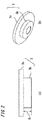
- FIG. 2 shows a disk-shaped metal fitting 3 as a button-shaped metal fitting
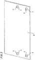
- FIG. 3 is a perspective view showing a partition plate 4
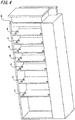
- FIG. 4 is a perspective view of the switchboard in which partition plates 4 have been attached to a case 6.
- FIG. 5 is a perspective view for illustrating how the functional unit 10 is slid on the partition plate 4
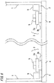
- FIG. 6 is a front view illustrating engagement between slide rails 2 and disk-shaped metal fittings 3
- FIG. 7 is a perspective view showing a front panel 7 and side plates 1 of the functional unit 10
- FIG. 8 is a bottom view showing the front panel 7 and the side plates 1 of the functional unit 10.
- each slide rail 2 is provided with a projecting portion A extending in the leftward/rightward direction on the front side, and a projecting portion B extending in the upward direction on the back side.
- the projecting portions A and B function as stoppers so as to prevent the functional unit 10 from being excessively slid to the back when the functional unit 10 is inserted into the case 6.
- a grip serving as a contact element with a load bus is to be connected to a side surface of the functional unit 10. For this reason, the length of the right side plate 1 of the functional unit 10 is made smaller so as to ensure a space for connection of the grip at the right back of the functional unit 10.
- FIG. 2(a) is a front view of the disk-shaped metal fitting 3
- FIG. 2(b) is a perspective view of the disk-shaped metal fitting 3.
- the disk-shaped metal fitting 3 has a two-stage structure including an upper-stage portion 3a and a lower-stage portion 3b.
- the diameter of the lower-stage portion 3b is smaller than the diameter of the upper-stage portion 3a, and the height H of the lower-stage portion 3b is slightly larger than the thickness of the slide rail 2.
- a plurality of (in this case, two) disk-shaped metal fittings 3 are attached to the top surface of the partition plate 4 for each of left and right sides of the partition plate 4.
- An attachment hole is formed in the center of each disk-shaped metal fitting 3, and the disk-shaped metal fitting 3 is attached to the partition plate 4 with a bolt 5.
- the guide rail according to the present embodiment includes a rail guide composed of the plurality of disk-shaped metal fittings 3 attached onto the partition plate 4, and slide rails 2. Then, the partition plate 4 to which the rail guide (disk-shaped metal fittings 3) is attached is attached inside the case 6, as shown in FIG. 4.
- FIG. 4 shows a state before the functional unit 10 is inserted into the functional unit compartment, which is a space partitioned by the partition plate 4.
- the functional unit 10 is slid toward the back side, which is the direction indicated by the arrow, while being placed on the partition plate 4, and the functional unit 10 is inserted into the functional unit compartment in the case 6, as shown in FIG. 5 .
- the functional unit 10 is slid on the partition plate 4 toward the front side.
- FIG. 6 is a front view as seen from the direction of an arrow X-X in FIG. 5 . It is noted that, in FIGS. 5 and 6 , the illustration of the inside functional unit 10 sandwiched between the side plates 1 and a front panel 7 described below is omitted.
- the slide rails 2 and the disk-shaped metal fittings 3 are formed in such dimensions and positions that an end portion of each of the slide rails 2 is sandwiched between the outer circumferential portion of the upper-stage portion 3a of the disk-shaped metal fitting 3 and the partition plate 4. It is noted that, of the plurality of disk-shaped metal fittings 3 disposed for each of the left and right sides of the partition plate 4, the front-most disk-shaped metal fitting 3 is disposed so as to correspond to the position of the projecting portion A of the slide rail 2 at the time of completion of the insertion of the functional unit 10.
- the end portion of the slide rail 2 is slid in a region sandwiched between the outer circumferential portion of the upper-stage portion 3a of the disk-shaped metal fitting 3 and the partition plate 4. That is, the slide rail 2 is engaged with the rail guide (disk-shaped metal fittings 3), and the movements of the slide rail 2 in the right-left direction and the up-down direction are inhibited.
- the lower-stage portion 3b of each of the disk-shaped metal fittings 3 serves as a stopper for the slide rail 2 in the right-left direction
- the upper-stage portion 3a of each of the disk-shaped metal fittings 3 serves as a stopper for the slide rail 2 in the upward direction. It is noted that, since the slide rail 2 is slid on the partition plate 4, the movement thereof in the downward direction is prevented by the partition plate 4.
- the functional unit 10 is provided with a front panel 7, and the above-described insertion of the functional unit 10 into the case 6 is performed using handles 7a provided on the front panel 7.
- the bottom surfaces of the left and right slide rails 2 and the bottom surface of the front panel 7 are formed to be flush with each other, and the bottom surfaces of the slide rails 2 and the bottom surface of the front panel 7 are slid on the partition plate 4 while being in contact with the surface of the partition plate 4 at the time of insertion and drawing of the functional unit 10 into and from the case 6.
- the functional unit 10 When the functional unit 10 is placed outside the case 6, after being taken out from the case 6, the functional unit 10 can be supported by the bottom surfaces of the slide rails 2 and the bottom surface of the front panel 7, and thus can be horizontally placed without the need for a spacer.
- the front panel 7 may be formed at a height at which the bottom portion thereof does not reach the slide rails 2, and the functional unit 10 can be supported by the bottom surfaces of the left and right slide rails 2 when the functional unit 10 is taken out from the case 6 and placed outside.
- the guide rail for sliding the functional unit 10 on the partition plate 4 forward and backward inside the case 6 is formed by the slide rail 2 provided on the bottom portion of each of the side plates 1 and the rail guide composed of the plurality of disk-shaped metal fittings 3 attached onto the partition plate 4.
- the rail guide includes a plurality of disk-shaped metal fittings 3 for each of the left and right sides of the partition plate 4, and is engaged with the slide rails 2 so as to serve as a stopper for the slide rails 2 in the right-left direction and the upward direction when the functional unit 10 is slid.
- the movements of the functional unit 10 in the right-left direction and the up-down direction are inhibited when the functional unit 10 is slid on the partition plate 4 forward and backward inside the case 6, and the functional unit 10 is prevented from being uplifted when the grip is connected to the functional unit 10, thus allowing the functional unit 10 to be reliably attached/removed and held with respect to the case 6. This also improves the reliability of the switchboard.
- the functional unit 10 can be horizontally placed outside the case in a stable manner without the need for a spacer, resulting in improved convenience.
- the rail guide is formed by attaching the small disk-shaped metal fittings 3 to the partition plate 4, the guide rail can be easily formed at a low cost.
- the slide rail 2 is formed by bending the bottom portion of the side plate 1, the guide rail can be more easily formed at a lower cost.
- Each of the disk-shaped metal fittings 3 of the rail guide has a two-stage structure in which the diameter of the lower-stage portion 3b is smaller than the diameter of the upper-stage portion 3a, and the height of the lower-stage portion 3b is larger than the thickness of the slide rail 2, so that the lower-stage portion 3b serves as a stopper for the slide rail in the right-left direction, and the upper-stage portion 3a serves as a stopper for the slide rail 2 in the upward direction. Accordingly, the rail guide that is engaged with the slide rail 2 so as to serve as the stopper for the slide rail 2 in the right-left direction and the upward direction can be easily and reliably obtained.
- each of the disk-shaped metal fittings 3 of the rail guide may be a button-shaped metal fitting having a shape such as a polygonal shape other than a disk shape, whereby the same effect can be obtained.
- the above-described embodiment shows an example in which the right side plate 1 of the functional unit 10 has a larger length.
- the embodiment can be applied to the case where left and right side plates 1 have an equal length, and also in this case, the same effect can be obtained.
- left and right side plates 1 having an equal length that are coupled together on the front side and the back side may be used, whereby the same effect can be obtained.
- the slide rails 2 of the left and right side plates 1 are connected with a coupling portion 2A provided on the front side and a coupling portion 2B provided on the back side.
- the coupling portion 2B on the back side is formed perpendicularly to the slide rail 2.
- the coupling portions 2A and 2B function as a stopper and prevent the functional unit 10 from being excessively slid to the back when the functional unit 10 is inserted into the case 6.
- a functional unit 10 of the switchboard includes a bottom plate for attaching a plurality of devices such as a circuit breaker and an electromagnetic switch.
- the guide rail includes slide rails 2 and a plurality of disk-shaped metal fittings 3 that are the same as those of Embodiment 1, and further includes a slide piece provided on the bottom plate of the functional unit 10, and guide pieces that are engaged with the slide piece.
- the rest of the structure of the switchboard is the same as that of Embodiment 1.
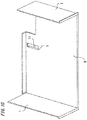
- FIG. 10 is a perspective view showing a bottom plate 8 and side plates 1 of the functional unit 10
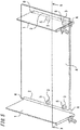
- FIG. 11 is a perspective view showing a partition plate 4
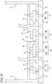
- FIG. 12 is a front view illustrating engagement of slide rails 2 and a slide piece 9 with disk-shaped metal fittings 3 and 13 serving as a rail guide
- FIG. 13 is a top view in which the bottom plate 8 and the side plates 1 of the functional unit 10 are disposed on the partition plate 4.
- a central portion on the back side of the bottom plate 8 of the functional unit 10 is cut in a rectangular shape by cutting out three sides, and then bent perpendicularly to the bottom surface, whereby a rectangular slide piece 9 having long sides extending in parallel to the sliding direction of the functional unit 10 is formed on the rear surface of the bottom plate 8.
- an opening 11 is formed in the bottom plate 8.
- the bottom plate 8 has a cut-out portion formed at the right back portion thereof in order to create a space for connecting a grip to the functional unit 10.
- the partition plate 4 that is attached to the case 6 is provided with disk-shaped metal fittings 3 that are engaged with the slide rails 2, and disk-shaped metal fittings 13 serving as guide pieces that are engaged with the slide pieces 9.
- a plurality of (in this case, two) disk-shaped metal fittings 3 are provided for each of the left and right sides of the partition plate 4 as in Embodiment 1.
- two disk-shaped metal fittings 13 that are engaged with the slide piece are provided at positions that sandwich the slide piece 9 at the central portion on the back side of the partition plate 4.
- Each of the disk-shaped metal fittings 13 is the same fitting part as the disk-shaped metal fitting 3, and is composed of an upper-stage portion 13a and a lower-stage portion 13b.
- the disk-shaped metal fittings 3 and 13 are attached to the top surface of the partition plate 4 using bolts 5.
- a rail guide is formed by the disk-shaped metal fittings 3 and 13 provided on the partition plate 4, and the rail guide, together with the slide rail 2 and the slide piece 9, form a guide rail.
- the functional unit 10 is slid toward the back while being placed on the partition plate 4, and the functional unit 10 is inserted into the functional unit compartment inside the case 6, as in Embodiment 1.
- the functional unit 10 is slid toward the front on the partition plate 4.
- each of the slide rails 2 is engaged with the rail guide (disk-shaped metal fittings 3), and the movements of the slide rail 2 in the right-left direction and the up-down direction are inhibited.
- the slide piece 9 passes between the two disk-shaped metal fittings 13 serving as the guide pieces.
- the two disk-shaped metal fittings 13 serve as a stopper for the slide piece in the right-left direction, and the movements of the functional unit 10 in the right-left direction are further inhibited.
- the slide piece 9 and the disk-shaped metal fittings 13 are further provided in addition to the slide rails 2 and the disk-shaped metal fittings 3, so that the functional unit 10 can be attached/removed and held with respect to the case 6 more reliably.
- the functional unit 10 can be attached/removed and held with respect to the case 6 more reliably.
- a high positional accuracy is required for connection of the grip. The required positional accuracy can be satisfied since the slide piece 9 and the disk-shaped metal fittings 13 are provided on the bottom plate 8 and the central portion on the back side of the partition plate 4.
- the slide rail 2 is provided on the bottom portion of each of the side plates of the functional unit 10, so that the functional unit 10 can be horizontally placed outside the case in a stable manner without the need for a spacer, resulting in improved convenience.
- the present embodiment uses the disk-shaped metal fittings 13 as the guide pieces that are engaged with the slide piece 9, the whole of the rail guide can be formed using the same fittings (disk-shaped metal fittings 3 and 13), so that the rail guide can be easily formed at a low cost. Furthermore, the slide piece 9 is formed by cutting out and bending a part of the bottom plate 8, and thus can be easily formed at a low cost.
- the guide pieces do not necessarily have a two-stage structure. Small fittings other than the disk-shaped metal fittings 13 can be used as the guide pieces, and any number of fittings may be used as long as the same number of fittings are provided at the left and the right.
- slide piece 9 may be formed by attaching another member to the rear surface of the bottom plate 8.
- This embodiment can also be applied to the case where the left and right side plates 1 have an equal length, as in Embodiment 1.
- the bottom plate 8 is also formed right-left symmetrical without a cut-out portion provided at the right back portion.
- the left and right side plates 1 coupled together by providing the coupling portions 2A and 2B may be used.
- Embodiments 1 and 2 above are not limited to a switchboard, and can be applied to a control center including a guide rail, a case 6, a partition plate 4, and a functional unit 10, wherein the functional unit 10 is attached and removed into and from the case 6 by being slid on the partition plate 4 forward and backward in the case 6.
Landscapes
- Engineering & Computer Science (AREA)
- Power Engineering (AREA)
- Patch Boards (AREA)
- Trip Switchboards (AREA)
- Casings For Electric Apparatus (AREA)
Abstract
Description
- The present invention relates to a control center such as a switchboard that stores a plurality of functional units, and particularly relates to a guide rail for attaching and removing each of the functional units to and from a functional unit compartment in a case.
- In general, a control center such as a switchboard used, for example, in an electric power facility or a plant facility stores a plurality of functional units, and is structured to compartmentalize the functional units using partition plates, and to allow each of the functional units to be attached/removed and held.
- In the conventional control centers, a guide rail member is attached to both sides of a frame case located in a functional unit compartment. In addition, guide pieces are attached to each functional unit. The guide pieces are engaged with each guide rail member, and are guided by the guide rail member so as to allow the functional unit to be attached/removed and held. Each guide rail member is disposed, for example, in the vicinity of the lower side of the corresponding partition plate, and each guide piece is disposed on the upper side of the corresponding functional unit, thus allowing the functional unit to be attached/removed and held in a suspended state (see e.g., Patent Document 1).
- Japanese Laid-Open Patent Publication No.
2011-211782 - With the conventional control center described in
Patent Document 1 above, the guide pieces provided at the upper portions of both side surfaces of the functional unit are engaged with groove-shaped portions of guide rails on the case side, and the functional unit is attached/removed and held in a suspended state, thus inhibiting leftward/rightward movement of the functional unit. - However, since the guide pieces are engaged with the groove-shaped portions while being placed on the guide rails, it is not possible to inhibit uplift of the functional unit. In particular, the functional unit is uplifted when a contact element of the functional unit is connected to a bus on the case side. This poses the problem that the functional unit cannot be reliably attached and removed to and from the case.
- Furthermore, when the bottom of the functional unit is not planar, a spacer is needed when the functional unit is taken out from the case and horizontally placed outside the case.
- The present invention has been made to solve the above-described problems, and an object of the present invention is to provide a structure of a guide rail that allows a functional unit to be reliably attached and removed to and from a case by inhibiting the movement of the functional unit in the right-left direction and the up-down direction, and enables the functional unit to be horizontally placed outside the case without the need for a spacer.
- A further object of the present invention is to provide a structure of a control center that is suitable for the above-described guide rail.
- A guide rail according to the present invention includes: a rail guide to be attached to a top surface of a partition plate partitioning a case into a plurality of functional unit compartments; and a slide rail provided at a bottom portion of a side plate of a functional unit and for sliding the functional unit on the partition plate forward and backward inside the case, wherein the rail guide includes a plurality of button-shaped metal fittings for each of left and right sides of the partition plate, and serves as a stopper for the slide rail in a right-left direction and an upward direction by the button-shaped metal fittings being engaged with the slide rail when the functional unit is slid.
- A control center according to the present invention includes the above-described guide rail; the case; the partition plate; and the functional unit, wherein the functional unit is attached and removed into and from each functional unit compartment inside the case by being slid on the partition plate forward and backward inside the case.
- With the guide rail according to the present invention, when sliding a functional unit on a partition plate forward and backward inside a case, the functional unit can be reliably attached and removed to and from the case by inhibiting movement of the functional unit in the right-left direction and the up-down direction by the rail guide and the slide rail. Furthermore, since the slide rail is provided at the bottom portion of the side plate of the functional unit, the functional unit can be horizontally placed outside the case without the need for a spacer.
- The control center according to the present invention includes the above-described guide rail, and, therefore, the functional unit can be reliably attached and removed to and from the case, resulting in improved reliability of the control center. Furthermore, since the functional unit can be horizontally placed outside the case without the need for a spacer, the convenience of the control center is also improved.
-
-
FIG. 1 is a perspective view showing a functional unit and side plates thereof, according toEmbodiment 1 of the present invention. -
FIG. 2 shows diagrams showing a disk-shaped metal fitting according toEmbodiment 1 of the present invention. -
FIG. 3 is a perspective view showing a partition plate according toEmbodiment 1 of the present invention. -
FIG. 4 is a perspective view of a switchboard in which partition plates are attached to a case, according toEmbodiment 1 of the present invention. -
FIG. 5 is a perspective view for illustrating how the functional unit is slid on the partition plate, according toEmbodiment 1 of the present invention. -
FIG. 6 is a front view illustrating engagement between slide rails and disk-shaped metal fittings according to Embodiment 1 of the present invention. -
FIG. 7 is a perspective view showing a front panel and side plates of the functional unit according toEmbodiment 1 of the present invention. -
FIG. 8 is a bottom view showing the front panel and the side plates of the functional unit according toEmbodiment 1 of the present invention. -
FIG. 9 is a perspective view showing a side plate of a functional unit according to another example ofEmbodiment 1 of the present invention. -
FIG. 10 is a perspective view showing a bottom plate and side plates of a functional unit according toEmbodiment 2 of the present invention. -
FIG. 11 is a perspective view showing a partition plate according toEmbodiment 2 of the present invention. -
FIG. 12 is a front view illustrating engagement of slide rails and slide pieces with disk-shaped metal fittings according to Embodiment 2 of the present invention. -
FIG. 13 is a top view in which the bottom plate and the side plates of the functional unit are disposed on the partition plate according toEmbodiment 2 of the present invention. - In the following, a switchboard as a control center according to
Embodiment 1 of the present invention will be described. The switchboard stores a plurality of functional units in a case, and is structured to compartmentalize the functional units using partition plates, and to allow each of the functional unit to be attached/removed and held. -
FIGS. 1 to 8 show the switchboard according toEmbodiment 1 of the present invention.FIG. 1 is a perspective view showing afunctional unit 10 andside plates 1 thereof,FIG. 2 shows a disk-shaped metal fitting 3 as a button-shaped metal fitting,FIG. 3 is a perspective view showing apartition plate 4, andFIG. 4 is a perspective view of the switchboard in whichpartition plates 4 have been attached to acase 6.FIG. 5 is a perspective view for illustrating how thefunctional unit 10 is slid on thepartition plate 4,FIG. 6 is a front view illustrating engagement betweenslide rails 2 and disk-shaped metal fittings 3,FIG. 7 is a perspective view showing afront panel 7 andside plates 1 of thefunctional unit 10, andFIG. 8 is a bottom view showing thefront panel 7 and theside plates 1 of thefunctional unit 10. - As shown in
FIG. 1 , the bottom portion of each of theside plates 1 of thefunctional unit 10 is bent into an L-shape to form theslide rail 2. Eachslide rail 2 is provided with a projecting portion A extending in the leftward/rightward direction on the front side, and a projecting portion B extending in the upward direction on the back side. The projecting portions A and B function as stoppers so as to prevent thefunctional unit 10 from being excessively slid to the back when thefunctional unit 10 is inserted into thecase 6. A grip serving as a contact element with a load bus is to be connected to a side surface of thefunctional unit 10. For this reason, the length of theright side plate 1 of thefunctional unit 10 is made smaller so as to ensure a space for connection of the grip at the right back of thefunctional unit 10. -
FIG. 2(a) is a front view of the disk-shaped metal fitting 3, andFIG. 2(b) is a perspective view of the disk-shaped metal fitting 3. As shown inFIG. 2 , the disk-shaped metal fitting 3 has a two-stage structure including an upper-stage portion 3a and a lower-stage portion 3b. The diameter of the lower-stage portion 3b is smaller than the diameter of the upper-stage portion 3a, and the height H of the lower-stage portion 3b is slightly larger than the thickness of theslide rail 2. Then, as shown inFIG. 3 , a plurality of (in this case, two) disk-shaped metal fittings 3 are attached to the top surface of thepartition plate 4 for each of left and right sides of thepartition plate 4. An attachment hole is formed in the center of each disk-shaped metal fitting 3, and the disk-shaped metal fitting 3 is attached to thepartition plate 4 with abolt 5. - The guide rail according to the present embodiment includes a rail guide composed of the plurality of disk-
shaped metal fittings 3 attached onto thepartition plate 4, andslide rails 2. Then, thepartition plate 4 to which the rail guide (disk-shaped metal fittings 3) is attached is attached inside thecase 6, as shown inFIG. 4. FIG. 4 shows a state before thefunctional unit 10 is inserted into the functional unit compartment, which is a space partitioned by thepartition plate 4. - To insert the
functional unit 10 into thecase 6, thefunctional unit 10 is slid toward the back side, which is the direction indicated by the arrow, while being placed on thepartition plate 4, and thefunctional unit 10 is inserted into the functional unit compartment in thecase 6, as shown inFIG. 5 . To pull out thefunctional unit 10 from thecase 6, thefunctional unit 10 is slid on thepartition plate 4 toward the front side. -
FIG. 6 is a front view as seen from the direction of an arrow X-X inFIG. 5 . It is noted that, inFIGS. 5 and6 , the illustration of the insidefunctional unit 10 sandwiched between theside plates 1 and afront panel 7 described below is omitted. - As shown in
FIG. 6 , theslide rails 2 and the disk-shaped metal fittings 3 are formed in such dimensions and positions that an end portion of each of theslide rails 2 is sandwiched between the outer circumferential portion of the upper-stage portion 3a of the disk-shaped metal fitting 3 and thepartition plate 4. It is noted that, of the plurality of disk-shaped metal fittings 3 disposed for each of the left and right sides of thepartition plate 4, the front-most disk-shaped metal fitting 3 is disposed so as to correspond to the position of the projecting portion A of theslide rail 2 at the time of completion of the insertion of thefunctional unit 10. - Then, when the
functional unit 10 is slid, the end portion of theslide rail 2 is slid in a region sandwiched between the outer circumferential portion of the upper-stage portion 3a of the disk-shapedmetal fitting 3 and thepartition plate 4. That is, theslide rail 2 is engaged with the rail guide (disk-shaped metal fittings 3), and the movements of theslide rail 2 in the right-left direction and the up-down direction are inhibited. At this time, the lower-stage portion 3b of each of the disk-shapedmetal fittings 3 serves as a stopper for theslide rail 2 in the right-left direction, and the upper-stage portion 3a of each of the disk-shapedmetal fittings 3 serves as a stopper for theslide rail 2 in the upward direction. It is noted that, since theslide rail 2 is slid on thepartition plate 4, the movement thereof in the downward direction is prevented by thepartition plate 4. - When the insertion of the
functional unit 10 is completed, the sliding is completed by the front-side projecting portion A of theslide rail 2 coming into contact with the lower-stage portion 3b of the disk-shapedmetal fitting 3, thus allowing thefunctional unit 10 to be stored at a predetermined position inside thecase 6. - As shown in
FIGS. 7 and8 , thefunctional unit 10 is provided with afront panel 7, and the above-described insertion of thefunctional unit 10 into thecase 6 is performed usinghandles 7a provided on thefront panel 7. - The bottom surfaces of the left and right slide rails 2 and the bottom surface of the
front panel 7 are formed to be flush with each other, and the bottom surfaces of the slide rails 2 and the bottom surface of thefront panel 7 are slid on thepartition plate 4 while being in contact with the surface of thepartition plate 4 at the time of insertion and drawing of thefunctional unit 10 into and from thecase 6. When thefunctional unit 10 is placed outside thecase 6, after being taken out from thecase 6, thefunctional unit 10 can be supported by the bottom surfaces of the slide rails 2 and the bottom surface of thefront panel 7, and thus can be horizontally placed without the need for a spacer. - It is noted that the
front panel 7 may be formed at a height at which the bottom portion thereof does not reach the slide rails 2, and thefunctional unit 10 can be supported by the bottom surfaces of the left and right slide rails 2 when thefunctional unit 10 is taken out from thecase 6 and placed outside. - As described above, according to the present embodiment, the guide rail for sliding the
functional unit 10 on thepartition plate 4 forward and backward inside thecase 6 is formed by theslide rail 2 provided on the bottom portion of each of theside plates 1 and the rail guide composed of the plurality of disk-shapedmetal fittings 3 attached onto thepartition plate 4. The rail guide includes a plurality of disk-shapedmetal fittings 3 for each of the left and right sides of thepartition plate 4, and is engaged with the slide rails 2 so as to serve as a stopper for the slide rails 2 in the right-left direction and the upward direction when thefunctional unit 10 is slid. - Accordingly, the movements of the
functional unit 10 in the right-left direction and the up-down direction are inhibited when thefunctional unit 10 is slid on thepartition plate 4 forward and backward inside thecase 6, and thefunctional unit 10 is prevented from being uplifted when the grip is connected to thefunctional unit 10, thus allowing thefunctional unit 10 to be reliably attached/removed and held with respect to thecase 6. This also improves the reliability of the switchboard. - Since the
slide rail 2 is provided on the bottom portion of each of the side plates of thefunctional unit 10, thefunctional unit 10 can be horizontally placed outside the case in a stable manner without the need for a spacer, resulting in improved convenience. - Furthermore, since the rail guide is formed by attaching the small disk-shaped
metal fittings 3 to thepartition plate 4, the guide rail can be easily formed at a low cost. - Since the
slide rail 2 is formed by bending the bottom portion of theside plate 1, the guide rail can be more easily formed at a lower cost. - Each of the disk-shaped
metal fittings 3 of the rail guide has a two-stage structure in which the diameter of the lower-stage portion 3b is smaller than the diameter of the upper-stage portion 3a, and the height of the lower-stage portion 3b is larger than the thickness of theslide rail 2, so that the lower-stage portion 3b serves as a stopper for the slide rail in the right-left direction, and the upper-stage portion 3a serves as a stopper for theslide rail 2 in the upward direction. Accordingly, the rail guide that is engaged with theslide rail 2 so as to serve as the stopper for theslide rail 2 in the right-left direction and the upward direction can be easily and reliably obtained. - It is noted that each of the disk-shaped
metal fittings 3 of the rail guide may be a button-shaped metal fitting having a shape such as a polygonal shape other than a disk shape, whereby the same effect can be obtained. - The above-described embodiment shows an example in which the
right side plate 1 of thefunctional unit 10 has a larger length. However, the embodiment can be applied to the case where left andright side plates 1 have an equal length, and also in this case, the same effect can be obtained. - As shown in
FIG. 9 , left andright side plates 1 having an equal length that are coupled together on the front side and the back side may be used, whereby the same effect can be obtained. - As shown in
FIG. 9 , the slide rails 2 of the left andright side plates 1 are connected with acoupling portion 2A provided on the front side and acoupling portion 2B provided on the back side. Thecoupling portion 2B on the back side is formed perpendicularly to theslide rail 2. In this case, thecoupling portions functional unit 10 from being excessively slid to the back when thefunctional unit 10 is inserted into thecase 6. - Next, a switchboard as a control center and a guide rail according to
Embodiment 2 of the present invention will be described with reference toFIGS. 10 to 13 . - Usually, a
functional unit 10 of the switchboard includes a bottom plate for attaching a plurality of devices such as a circuit breaker and an electromagnetic switch. InEmbodiment 2, the guide rail includesslide rails 2 and a plurality of disk-shapedmetal fittings 3 that are the same as those ofEmbodiment 1, and further includes a slide piece provided on the bottom plate of thefunctional unit 10, and guide pieces that are engaged with the slide piece. The rest of the structure of the switchboard is the same as that ofEmbodiment 1. -
FIG. 10 is a perspective view showing abottom plate 8 andside plates 1 of thefunctional unit 10,FIG. 11 is a perspective view showing apartition plate 4,FIG. 12 is a front view illustrating engagement ofslide rails 2 and aslide piece 9 with disk-shapedmetal fittings FIG. 13 is a top view in which thebottom plate 8 and theside plates 1 of thefunctional unit 10 are disposed on thepartition plate 4. - As shown in
FIG. 10 , a central portion on the back side of thebottom plate 8 of thefunctional unit 10 is cut in a rectangular shape by cutting out three sides, and then bent perpendicularly to the bottom surface, whereby arectangular slide piece 9 having long sides extending in parallel to the sliding direction of thefunctional unit 10 is formed on the rear surface of thebottom plate 8. At the same time, anopening 11 is formed in thebottom plate 8. In addition, thebottom plate 8 has a cut-out portion formed at the right back portion thereof in order to create a space for connecting a grip to thefunctional unit 10. - As shown in
FIG. 11 , thepartition plate 4 that is attached to thecase 6 is provided with disk-shapedmetal fittings 3 that are engaged with the slide rails 2, and disk-shapedmetal fittings 13 serving as guide pieces that are engaged with theslide pieces 9. As the plurality of disk-shapedmetal fittings 3 that are engaged with the slide rails 2, a plurality of (in this case, two) disk-shapedmetal fittings 3 are provided for each of the left and right sides of thepartition plate 4 as inEmbodiment 1. Then, two disk-shapedmetal fittings 13 that are engaged with the slide piece are provided at positions that sandwich theslide piece 9 at the central portion on the back side of thepartition plate 4. Each of the disk-shapedmetal fittings 13 is the same fitting part as the disk-shapedmetal fitting 3, and is composed of an upper-stage portion 13a and a lower-stage portion 13b. The disk-shapedmetal fittings partition plate 4 usingbolts 5. - In the present embodiment, a rail guide is formed by the disk-shaped
metal fittings partition plate 4, and the rail guide, together with theslide rail 2 and theslide piece 9, form a guide rail. - To insert the
functional unit 10 into thecase 6, thefunctional unit 10 is slid toward the back while being placed on thepartition plate 4, and thefunctional unit 10 is inserted into the functional unit compartment inside thecase 6, as inEmbodiment 1. To pull out thefunctional unit 10 from thecase 6, thefunctional unit 10 is slid toward the front on thepartition plate 4. - As shown in
FIG. 12 , when thefunctional unit 10 is slid, an end portion of each of the slide rails 2 is slid in a region sandwiched between the outer circumferential portion of the upper-stage portion 3a of the disk-shapedmetal fitting 3 and thepartition plate 4. That is, each of the slide rails 2 is engaged with the rail guide (disk-shaped metal fittings 3), and the movements of theslide rail 2 in the right-left direction and the up-down direction are inhibited. Then, prior to completion of the insertion of thefunctional unit 10, theslide piece 9 passes between the two disk-shapedmetal fittings 13 serving as the guide pieces. At this time, the two disk-shapedmetal fittings 13 serve as a stopper for the slide piece in the right-left direction, and the movements of thefunctional unit 10 in the right-left direction are further inhibited. - Thereafter, the insertion of the
functional unit 10 is completed while theslide piece 9 is being sandwiched between the left and right disk-shapedmetal fittings 13, as shown inFIG. 13 . - In the present embodiment, the
slide piece 9 and the disk-shapedmetal fittings 13 are further provided in addition to the slide rails 2 and the disk-shapedmetal fittings 3, so that thefunctional unit 10 can be attached/removed and held with respect to thecase 6 more reliably. In particular, on the back side of thefunctional unit 10, a high positional accuracy is required for connection of the grip. The required positional accuracy can be satisfied since theslide piece 9 and the disk-shapedmetal fittings 13 are provided on thebottom plate 8 and the central portion on the back side of thepartition plate 4. - In this case as well, the
slide rail 2 is provided on the bottom portion of each of the side plates of thefunctional unit 10, so that thefunctional unit 10 can be horizontally placed outside the case in a stable manner without the need for a spacer, resulting in improved convenience. - Since the present embodiment uses the disk-shaped
metal fittings 13 as the guide pieces that are engaged with theslide piece 9, the whole of the rail guide can be formed using the same fittings (disk-shapedmetal fittings 3 and 13), so that the rail guide can be easily formed at a low cost. Furthermore, theslide piece 9 is formed by cutting out and bending a part of thebottom plate 8, and thus can be easily formed at a low cost. - It is noted that the guide pieces do not necessarily have a two-stage structure. Small fittings other than the disk-shaped
metal fittings 13 can be used as the guide pieces, and any number of fittings may be used as long as the same number of fittings are provided at the left and the right. - Furthermore, the
slide piece 9 may be formed by attaching another member to the rear surface of thebottom plate 8. - This embodiment can also be applied to the case where the left and
right side plates 1 have an equal length, as inEmbodiment 1. In that case, thebottom plate 8 is also formed right-left symmetrical without a cut-out portion provided at the right back portion. As shown inFIG. 9 , the left andright side plates 1 coupled together by providing thecoupling portions - Embodiments 1 and 2 above are not limited to a switchboard, and can be applied to a control center including a guide rail, a
case 6, apartition plate 4, and afunctional unit 10, wherein thefunctional unit 10 is attached and removed into and from thecase 6 by being slid on thepartition plate 4 forward and backward in thecase 6. - It is noted that, within the scope of the present invention, the above-described embodiments may be freely combined with each other, or each of the above embodiments may be modified or simplified as appropriate.
Claims (6)
- A guide rail comprising:a rail guide to be attached to a top surface of a partition plate partitioning a case into a plurality of functional unit compartments; and a slide rail provided at a bottom portion of a side plate of a functional unit and for sliding the functional unit on the partition plate forward and backward inside the case,wherein the rail guide includes a plurality of button-shaped metal fittings for each of left and right sides of the partition plate, and serves as a stopper for the slide rail in a right-left direction and an upward direction by the button-shaped metal fittings being engaged with the slide rail when the functional unit is slid.
- The guide rail according to claim 1, wherein
the slide rail is formed by bending the bottom portion of the side plate. - The guide rail according to claim 1 or 2, wherein
the button-shaped metal fittings of the rail guide each have a two-stage structure in which a diameter of a lower-stage portion is smaller than a diameter of an upper-stage portion, a height of the lower-stage portion is larger than a thickness of the slide rail, the lower-stage portion serves as a stopper for the slide rail in the right-left direction, and the upper-stage portion serves as a stopper for the slide rail in an upward direction. - The guide rail according to any one of claims 1 to 3, comprising a rectangular slide piece having long sides extending in parallel to a sliding direction, the slide piece being provided on a rear surface of a central portion on a back side of a bottom plate of the functional unit, wherein
the rail guide includes guide pieces at positions sandwiching the slide piece on the top surface of the partition plate, and the guide pieces serve as a stopper for the slide piece in the right-left direction. - The guide rail according to claim 4, wherein
the slide piece is formed by cutting out and bending a part of the bottom plate of the functional unit, and the guide pieces are formed by the same fittings as the button-shaped metal fittings. - A control center comprising:the guide rail according to any one of claims 1 to 5 ;the case;the partition plate; andthe functional unit,wherein the functional unit is attached and removed into and from each functional unit compartment inside the case by being slid on the partition plate forward and backward inside the case.
Applications Claiming Priority (1)
| Application Number | Priority Date | Filing Date | Title |
|---|---|---|---|
| PCT/JP2016/081705 WO2018078739A1 (en) | 2016-10-26 | 2016-10-26 | Guide rail and control center including same |
Publications (3)
| Publication Number | Publication Date |
|---|---|
| EP3534471A1 true EP3534471A1 (en) | 2019-09-04 |
| EP3534471A4 EP3534471A4 (en) | 2019-11-06 |
| EP3534471B1 EP3534471B1 (en) | 2021-03-24 |
Family
ID=61158279
Family Applications (1)
| Application Number | Title | Priority Date | Filing Date |
|---|---|---|---|
| EP16920367.6A Active EP3534471B1 (en) | 2016-10-26 | 2016-10-26 | Control center including a guide rail |
Country Status (3)
| Country | Link |
|---|---|
| EP (1) | EP3534471B1 (en) |
| JP (1) | JP6274474B1 (en) |
| WO (1) | WO2018078739A1 (en) |
Family Cites Families (4)
| Publication number | Priority date | Publication date | Assignee | Title |
|---|---|---|---|---|
| JPS6223205Y2 (en) * | 1979-02-13 | 1987-06-13 | ||
| JPS58174912U (en) * | 1982-05-18 | 1983-11-22 | 富士電機株式会社 | control center unit |
| JP2601825B2 (en) * | 1987-06-26 | 1997-04-16 | 株式会社東芝 | Unit drawer for switchboard |
| KR20150011130A (en) * | 2013-07-22 | 2015-01-30 | 정승재 | Motor control center |
-
2016
- 2016-10-26 JP JP2017516790A patent/JP6274474B1/en active Active
- 2016-10-26 WO PCT/JP2016/081705 patent/WO2018078739A1/en not_active Ceased
- 2016-10-26 EP EP16920367.6A patent/EP3534471B1/en active Active
Also Published As
| Publication number | Publication date |
|---|---|
| EP3534471A4 (en) | 2019-11-06 |
| EP3534471B1 (en) | 2021-03-24 |
| JPWO2018078739A1 (en) | 2018-10-25 |
| JP6274474B1 (en) | 2018-02-07 |
| WO2018078739A1 (en) | 2018-05-03 |
Similar Documents
| Publication | Publication Date | Title |
|---|---|---|
| US9570722B2 (en) | Power storage device | |
| CN103915705B (en) | Electric connecting terminals and its assembly method | |
| US8573987B1 (en) | Power distribution box assembly | |
| US9667005B2 (en) | Base terminal block and auxiliary terminal block for switchboards and two-tier terminal block assembly comprising base terminal block and auxiliary terminal block | |
| EP3358647A1 (en) | Inter-battery connection device and inter-battery connection device assembly | |
| US10277015B2 (en) | Motor control center | |
| EP3929958A1 (en) | Relay | |
| SA113340764B1 (en) | Improvements in relating to electrical distribution boards | |
| CN107408654A (en) | For accommodating the switch cubicle or frame and corresponding switch cubicle or frame structure of electric energy accumulator, particularly battery | |
| JP2015133223A (en) | Battery connection module | |
| EP3813211A1 (en) | Bus bar protector | |
| JP2009195010A (en) | Housing for bus duct | |
| US10263399B2 (en) | Multiple latching feet for electrical connector assembly | |
| JP2013191288A (en) | Battery pack, power tool, battery charger, and power tool set | |
| US20130202380A1 (en) | Locking structure of screw fastening block | |
| US9054508B2 (en) | Electrical junction box | |
| JP4925974B2 (en) | Drawer type circuit breaker, terminal device of drawer type circuit breaker, and interphase insulating plate of terminal device | |
| EP3534471A1 (en) | Guide rail and control center including same | |
| JP5620236B2 (en) | Metal closed switchgear | |
| US9627869B2 (en) | Block for vehicle | |
| US9660362B2 (en) | Device for electrical connection having an auxiliary output, and switching appliance having such a device | |
| EP3627624A1 (en) | Connection structure of electrical equipment | |
| CN111480267A (en) | Terminal block and air conditioner | |
| US8894425B2 (en) | Connection system for connecting a single row housing to a terminal element | |
| EP3408860B1 (en) | Cradle for a narrow relay, cradle assembly and relay |
Legal Events
| Date | Code | Title | Description |
|---|---|---|---|
| STAA | Information on the status of an ep patent application or granted ep patent |
Free format text: STATUS: THE INTERNATIONAL PUBLICATION HAS BEEN MADE |
|
| PUAI | Public reference made under article 153(3) epc to a published international application that has entered the european phase |
Free format text: ORIGINAL CODE: 0009012 |
|
| STAA | Information on the status of an ep patent application or granted ep patent |
Free format text: STATUS: REQUEST FOR EXAMINATION WAS MADE |
|
| 17P | Request for examination filed |
Effective date: 20190219 |
|
| AK | Designated contracting states |
Kind code of ref document: A1 Designated state(s): AL AT BE BG CH CY CZ DE DK EE ES FI FR GB GR HR HU IE IS IT LI LT LU LV MC MK MT NL NO PL PT RO RS SE SI SK SM TR |
|
| AX | Request for extension of the european patent |
Extension state: BA ME |
|
| A4 | Supplementary search report drawn up and despatched |
Effective date: 20191007 |
|
| RIC1 | Information provided on ipc code assigned before grant |
Ipc: H02B 1/36 20060101ALI20190930BHEP Ipc: H02B 11/12 20060101AFI20190930BHEP |
|
| DAV | Request for validation of the european patent (deleted) | ||
| DAX | Request for extension of the european patent (deleted) | ||
| GRAP | Despatch of communication of intention to grant a patent |
Free format text: ORIGINAL CODE: EPIDOSNIGR1 |
|
| STAA | Information on the status of an ep patent application or granted ep patent |
Free format text: STATUS: GRANT OF PATENT IS INTENDED |
|
| INTG | Intention to grant announced |
Effective date: 20200917 |
|
| GRAS | Grant fee paid |
Free format text: ORIGINAL CODE: EPIDOSNIGR3 |
|
| GRAA | (expected) grant |
Free format text: ORIGINAL CODE: 0009210 |
|
| STAA | Information on the status of an ep patent application or granted ep patent |
Free format text: STATUS: THE PATENT HAS BEEN GRANTED |
|
| AK | Designated contracting states |
Kind code of ref document: B1 Designated state(s): AL AT BE BG CH CY CZ DE DK EE ES FI FR GB GR HR HU IE IS IT LI LT LU LV MC MK MT NL NO PL PT RO RS SE SI SK SM TR |
|
| REG | Reference to a national code |
Ref country code: GB Ref legal event code: FG4D |
|
| REG | Reference to a national code |
Ref country code: CH Ref legal event code: EP |
|
| REG | Reference to a national code |
Ref country code: DE Ref legal event code: R096 Ref document number: 602016055067 Country of ref document: DE |
|
| REG | Reference to a national code |
Ref country code: IE Ref legal event code: FG4D |
|
| REG | Reference to a national code |
Ref country code: AT Ref legal event code: REF Ref document number: 1375467 Country of ref document: AT Kind code of ref document: T Effective date: 20210415 |
|
| REG | Reference to a national code |
Ref country code: LT Ref legal event code: MG9D |
|
| PG25 | Lapsed in a contracting state [announced via postgrant information from national office to epo] |
Ref country code: BG Free format text: LAPSE BECAUSE OF FAILURE TO SUBMIT A TRANSLATION OF THE DESCRIPTION OR TO PAY THE FEE WITHIN THE PRESCRIBED TIME-LIMIT Effective date: 20210624 Ref country code: FI Free format text: LAPSE BECAUSE OF FAILURE TO SUBMIT A TRANSLATION OF THE DESCRIPTION OR TO PAY THE FEE WITHIN THE PRESCRIBED TIME-LIMIT Effective date: 20210324 Ref country code: HR Free format text: LAPSE BECAUSE OF FAILURE TO SUBMIT A TRANSLATION OF THE DESCRIPTION OR TO PAY THE FEE WITHIN THE PRESCRIBED TIME-LIMIT Effective date: 20210324 Ref country code: GR Free format text: LAPSE BECAUSE OF FAILURE TO SUBMIT A TRANSLATION OF THE DESCRIPTION OR TO PAY THE FEE WITHIN THE PRESCRIBED TIME-LIMIT Effective date: 20210625 Ref country code: NO Free format text: LAPSE BECAUSE OF FAILURE TO SUBMIT A TRANSLATION OF THE DESCRIPTION OR TO PAY THE FEE WITHIN THE PRESCRIBED TIME-LIMIT Effective date: 20210624 |
|
| PG25 | Lapsed in a contracting state [announced via postgrant information from national office to epo] |
Ref country code: SE Free format text: LAPSE BECAUSE OF FAILURE TO SUBMIT A TRANSLATION OF THE DESCRIPTION OR TO PAY THE FEE WITHIN THE PRESCRIBED TIME-LIMIT Effective date: 20210324 Ref country code: LV Free format text: LAPSE BECAUSE OF FAILURE TO SUBMIT A TRANSLATION OF THE DESCRIPTION OR TO PAY THE FEE WITHIN THE PRESCRIBED TIME-LIMIT Effective date: 20210324 Ref country code: RS Free format text: LAPSE BECAUSE OF FAILURE TO SUBMIT A TRANSLATION OF THE DESCRIPTION OR TO PAY THE FEE WITHIN THE PRESCRIBED TIME-LIMIT Effective date: 20210324 |
|
| REG | Reference to a national code |
Ref country code: NL Ref legal event code: MP Effective date: 20210324 |
|
| REG | Reference to a national code |
Ref country code: AT Ref legal event code: MK05 Ref document number: 1375467 Country of ref document: AT Kind code of ref document: T Effective date: 20210324 |
|
| PG25 | Lapsed in a contracting state [announced via postgrant information from national office to epo] |
Ref country code: NL Free format text: LAPSE BECAUSE OF FAILURE TO SUBMIT A TRANSLATION OF THE DESCRIPTION OR TO PAY THE FEE WITHIN THE PRESCRIBED TIME-LIMIT Effective date: 20210324 |
|
| PG25 | Lapsed in a contracting state [announced via postgrant information from national office to epo] |
Ref country code: LT Free format text: LAPSE BECAUSE OF FAILURE TO SUBMIT A TRANSLATION OF THE DESCRIPTION OR TO PAY THE FEE WITHIN THE PRESCRIBED TIME-LIMIT Effective date: 20210324 Ref country code: EE Free format text: LAPSE BECAUSE OF FAILURE TO SUBMIT A TRANSLATION OF THE DESCRIPTION OR TO PAY THE FEE WITHIN THE PRESCRIBED TIME-LIMIT Effective date: 20210324 Ref country code: CZ Free format text: LAPSE BECAUSE OF FAILURE TO SUBMIT A TRANSLATION OF THE DESCRIPTION OR TO PAY THE FEE WITHIN THE PRESCRIBED TIME-LIMIT Effective date: 20210324 Ref country code: AT Free format text: LAPSE BECAUSE OF FAILURE TO SUBMIT A TRANSLATION OF THE DESCRIPTION OR TO PAY THE FEE WITHIN THE PRESCRIBED TIME-LIMIT Effective date: 20210324 Ref country code: SM Free format text: LAPSE BECAUSE OF FAILURE TO SUBMIT A TRANSLATION OF THE DESCRIPTION OR TO PAY THE FEE WITHIN THE PRESCRIBED TIME-LIMIT Effective date: 20210324 |
|
| PG25 | Lapsed in a contracting state [announced via postgrant information from national office to epo] |
Ref country code: IS Free format text: LAPSE BECAUSE OF FAILURE TO SUBMIT A TRANSLATION OF THE DESCRIPTION OR TO PAY THE FEE WITHIN THE PRESCRIBED TIME-LIMIT Effective date: 20210724 Ref country code: PL Free format text: LAPSE BECAUSE OF FAILURE TO SUBMIT A TRANSLATION OF THE DESCRIPTION OR TO PAY THE FEE WITHIN THE PRESCRIBED TIME-LIMIT Effective date: 20210324 Ref country code: PT Free format text: LAPSE BECAUSE OF FAILURE TO SUBMIT A TRANSLATION OF THE DESCRIPTION OR TO PAY THE FEE WITHIN THE PRESCRIBED TIME-LIMIT Effective date: 20210726 Ref country code: RO Free format text: LAPSE BECAUSE OF FAILURE TO SUBMIT A TRANSLATION OF THE DESCRIPTION OR TO PAY THE FEE WITHIN THE PRESCRIBED TIME-LIMIT Effective date: 20210324 Ref country code: SK Free format text: LAPSE BECAUSE OF FAILURE TO SUBMIT A TRANSLATION OF THE DESCRIPTION OR TO PAY THE FEE WITHIN THE PRESCRIBED TIME-LIMIT Effective date: 20210324 |
|
| REG | Reference to a national code |
Ref country code: DE Ref legal event code: R097 Ref document number: 602016055067 Country of ref document: DE |
|
| PG25 | Lapsed in a contracting state [announced via postgrant information from national office to epo] |
Ref country code: DK Free format text: LAPSE BECAUSE OF FAILURE TO SUBMIT A TRANSLATION OF THE DESCRIPTION OR TO PAY THE FEE WITHIN THE PRESCRIBED TIME-LIMIT Effective date: 20210324 Ref country code: AL Free format text: LAPSE BECAUSE OF FAILURE TO SUBMIT A TRANSLATION OF THE DESCRIPTION OR TO PAY THE FEE WITHIN THE PRESCRIBED TIME-LIMIT Effective date: 20210324 Ref country code: ES Free format text: LAPSE BECAUSE OF FAILURE TO SUBMIT A TRANSLATION OF THE DESCRIPTION OR TO PAY THE FEE WITHIN THE PRESCRIBED TIME-LIMIT Effective date: 20210324 |
|
| PLBE | No opposition filed within time limit |
Free format text: ORIGINAL CODE: 0009261 |
|
| STAA | Information on the status of an ep patent application or granted ep patent |
Free format text: STATUS: NO OPPOSITION FILED WITHIN TIME LIMIT |
|
| PG25 | Lapsed in a contracting state [announced via postgrant information from national office to epo] |
Ref country code: SI Free format text: LAPSE BECAUSE OF FAILURE TO SUBMIT A TRANSLATION OF THE DESCRIPTION OR TO PAY THE FEE WITHIN THE PRESCRIBED TIME-LIMIT Effective date: 20210324 |
|
| 26N | No opposition filed |
Effective date: 20220104 |
|
| REG | Reference to a national code |
Ref country code: CH Ref legal event code: PL |
|
| PG25 | Lapsed in a contracting state [announced via postgrant information from national office to epo] |
Ref country code: IS Free format text: LAPSE BECAUSE OF FAILURE TO SUBMIT A TRANSLATION OF THE DESCRIPTION OR TO PAY THE FEE WITHIN THE PRESCRIBED TIME-LIMIT Effective date: 20210724 |
|
| REG | Reference to a national code |
Ref country code: BE Ref legal event code: MM Effective date: 20211031 |
|
| GBPC | Gb: european patent ceased through non-payment of renewal fee |
Effective date: 20211026 |
|
| PG25 | Lapsed in a contracting state [announced via postgrant information from national office to epo] |
Ref country code: MC Free format text: LAPSE BECAUSE OF FAILURE TO SUBMIT A TRANSLATION OF THE DESCRIPTION OR TO PAY THE FEE WITHIN THE PRESCRIBED TIME-LIMIT Effective date: 20210324 |
|
| PG25 | Lapsed in a contracting state [announced via postgrant information from national office to epo] |
Ref country code: LU Free format text: LAPSE BECAUSE OF NON-PAYMENT OF DUE FEES Effective date: 20211026 Ref country code: GB Free format text: LAPSE BECAUSE OF NON-PAYMENT OF DUE FEES Effective date: 20211026 Ref country code: BE Free format text: LAPSE BECAUSE OF NON-PAYMENT OF DUE FEES Effective date: 20211031 |
|
| PG25 | Lapsed in a contracting state [announced via postgrant information from national office to epo] |
Ref country code: LI Free format text: LAPSE BECAUSE OF NON-PAYMENT OF DUE FEES Effective date: 20211031 Ref country code: CH Free format text: LAPSE BECAUSE OF NON-PAYMENT OF DUE FEES Effective date: 20211031 |
|
| PG25 | Lapsed in a contracting state [announced via postgrant information from national office to epo] |
Ref country code: FR Free format text: LAPSE BECAUSE OF NON-PAYMENT OF DUE FEES Effective date: 20211031 |
|
| PG25 | Lapsed in a contracting state [announced via postgrant information from national office to epo] |
Ref country code: IE Free format text: LAPSE BECAUSE OF NON-PAYMENT OF DUE FEES Effective date: 20211026 |
|
| PG25 | Lapsed in a contracting state [announced via postgrant information from national office to epo] |
Ref country code: IT Free format text: LAPSE BECAUSE OF FAILURE TO SUBMIT A TRANSLATION OF THE DESCRIPTION OR TO PAY THE FEE WITHIN THE PRESCRIBED TIME-LIMIT Effective date: 20210324 |
|
| P01 | Opt-out of the competence of the unified patent court (upc) registered |
Effective date: 20230512 |
|
| PG25 | Lapsed in a contracting state [announced via postgrant information from national office to epo] |
Ref country code: CY Free format text: LAPSE BECAUSE OF FAILURE TO SUBMIT A TRANSLATION OF THE DESCRIPTION OR TO PAY THE FEE WITHIN THE PRESCRIBED TIME-LIMIT Effective date: 20210324 |
|
| PG25 | Lapsed in a contracting state [announced via postgrant information from national office to epo] |
Ref country code: HU Free format text: LAPSE BECAUSE OF FAILURE TO SUBMIT A TRANSLATION OF THE DESCRIPTION OR TO PAY THE FEE WITHIN THE PRESCRIBED TIME-LIMIT; INVALID AB INITIO Effective date: 20161026 |
|
| PG25 | Lapsed in a contracting state [announced via postgrant information from national office to epo] |
Ref country code: MK Free format text: LAPSE BECAUSE OF FAILURE TO SUBMIT A TRANSLATION OF THE DESCRIPTION OR TO PAY THE FEE WITHIN THE PRESCRIBED TIME-LIMIT Effective date: 20210324 |
|
| PG25 | Lapsed in a contracting state [announced via postgrant information from national office to epo] |
Ref country code: TR Free format text: LAPSE BECAUSE OF FAILURE TO SUBMIT A TRANSLATION OF THE DESCRIPTION OR TO PAY THE FEE WITHIN THE PRESCRIBED TIME-LIMIT Effective date: 20210324 |
|
| PG25 | Lapsed in a contracting state [announced via postgrant information from national office to epo] |
Ref country code: MT Free format text: LAPSE BECAUSE OF FAILURE TO SUBMIT A TRANSLATION OF THE DESCRIPTION OR TO PAY THE FEE WITHIN THE PRESCRIBED TIME-LIMIT Effective date: 20210324 |
|
| REG | Reference to a national code |
Ref country code: DE Ref legal event code: R084 Ref document number: 602016055067 Country of ref document: DE |
|
| PGFP | Annual fee paid to national office [announced via postgrant information from national office to epo] |
Ref country code: DE Payment date: 20250902 Year of fee payment: 10 |