EP3534330A1 - Detecting the presence of ice on a surface using ultraviolet light - Google Patents
Detecting the presence of ice on a surface using ultraviolet light Download PDFInfo
- Publication number
- EP3534330A1 EP3534330A1 EP19158333.5A EP19158333A EP3534330A1 EP 3534330 A1 EP3534330 A1 EP 3534330A1 EP 19158333 A EP19158333 A EP 19158333A EP 3534330 A1 EP3534330 A1 EP 3534330A1
- Authority
- EP
- European Patent Office
- Prior art keywords
- ice
- image
- light
- light source
- control device
- Prior art date
- Legal status (The legal status is an assumption and is not a legal conclusion. Google has not performed a legal analysis and makes no representation as to the accuracy of the status listed.)
- Granted
Links
Images




Classifications
-
- G—PHYSICS
- G06—COMPUTING OR CALCULATING; COUNTING
- G06T—IMAGE DATA PROCESSING OR GENERATION, IN GENERAL
- G06T7/00—Image analysis
- G06T7/0002—Inspection of images, e.g. flaw detection
- G06T7/0004—Industrial image inspection
- G06T7/0008—Industrial image inspection checking presence/absence
-
- B—PERFORMING OPERATIONS; TRANSPORTING
- B64—AIRCRAFT; AVIATION; COSMONAUTICS
- B64D—EQUIPMENT FOR FITTING IN OR TO AIRCRAFT; FLIGHT SUITS; PARACHUTES; ARRANGEMENT OR MOUNTING OF POWER PLANTS OR PROPULSION TRANSMISSIONS IN AIRCRAFT
- B64D15/00—De-icing or preventing icing on exterior surfaces of aircraft
- B64D15/20—Means for detecting icing or initiating de-icing
-
- B—PERFORMING OPERATIONS; TRANSPORTING
- B64—AIRCRAFT; AVIATION; COSMONAUTICS
- B64D—EQUIPMENT FOR FITTING IN OR TO AIRCRAFT; FLIGHT SUITS; PARACHUTES; ARRANGEMENT OR MOUNTING OF POWER PLANTS OR PROPULSION TRANSMISSIONS IN AIRCRAFT
- B64D15/00—De-icing or preventing icing on exterior surfaces of aircraft
- B64D15/20—Means for detecting icing or initiating de-icing
- B64D15/22—Automatic initiation by icing detector
-
- G—PHYSICS
- G06—COMPUTING OR CALCULATING; COUNTING
- G06T—IMAGE DATA PROCESSING OR GENERATION, IN GENERAL
- G06T7/00—Image analysis
- G06T7/0002—Inspection of images, e.g. flaw detection
- G06T7/0004—Industrial image inspection
- G06T7/001—Industrial image inspection using an image reference approach
-
- G—PHYSICS
- G06—COMPUTING OR CALCULATING; COUNTING
- G06T—IMAGE DATA PROCESSING OR GENERATION, IN GENERAL
- G06T7/00—Image analysis
- G06T7/90—Determination of colour characteristics
-
- G—PHYSICS
- G06—COMPUTING OR CALCULATING; COUNTING
- G06T—IMAGE DATA PROCESSING OR GENERATION, IN GENERAL
- G06T7/00—Image analysis
- G06T7/97—Determining parameters from multiple pictures
-
- G—PHYSICS
- G06—COMPUTING OR CALCULATING; COUNTING
- G06T—IMAGE DATA PROCESSING OR GENERATION, IN GENERAL
- G06T2207/00—Indexing scheme for image analysis or image enhancement
- G06T2207/10—Image acquisition modality
- G06T2207/10064—Fluorescence image
Definitions
- FAA regulation 14 C.F.R. ⁇ 25.1403 specifies a means of determining the presence of ice accretion on aircraft wings during night operations.
- a typical means for meeting this requirement uses flush-mounted lights installed on the fuselage which are pointed in the direction of the wing leading edge. These lights may use an incandescent or light-emitting diode (LED), visible light source and are intended to project enough light onto the leading edge of the wing to be a visual aid for the flight crew to see the wings.
- LED light-emitting diode
- Various examples of the present disclosure generally relate to methods, devices, systems, computer readable media, computer program products, carriers, signals, hardware and/or software that detects icing on a surface of a vehicle.
- Particular examples address a need for a system that provides or enables positive identification of ice, differentiation between an iced surface and a wet or dry surface, and/or automation of the ice detection process.
- Particular examples herein use ultraviolet wing illumination lights to identify and/or detect ice accretion on aircraft wings so that flight crew may be notified accordingly.
- Further examples automatically activate the aircraft ice protection systems, e.g., as an aid to flight crew while in flight.
- At least some examples include the use an ultraviolet light source in the UV-A wavelength range of 315 to 400 nanometers (nm) (sometimes known as a UV-A or black light) in the detection of icing on a surface of an aircraft.
- this detection is performed in real time on aircraft (e.g., transport-category commercial aircraft), and supports temperatures and conditions within the FAA icing regulations, e.g., 14 C.F.R. Part 25, Appendix C and Appendix O icing envelopes.
- the present disclosure include a system for detecting ice on a surface.
- the system comprises an ultraviolet (UV) light source configured to project light primarily in the UV-A spectrum onto the surface, an optical device configured to capture an image of the surface while the light primarily in the UV-A spectrum is projected by the UV light source, and a control device communicatively coupled to the optical device.
- the control device is configured to receive the image from the optical device and determine whether or not ice is present on the surface based respectively on whether or not visible light induced by the light projected by the UV light source is captured in the image.
- control device is further configured to signal an ice protection system communicatively coupled to the control device to deice the surface responsive to the control device detecting that the ice is present.
- control device is configured to detect whether or not luminescence is captured in the image.
- the UV light source and optical device are mounted on a fuselage of an aircraft and the surface is a surface of an airfoil. In some such examples the surface is aft of the UV light source and optical device on the fuselage.
- the control device is configured to compare the image to a baseline image of the surface in which ice is not present. In some such examples, to compare the image to the baseline image in which ice is not present on the surface, the control device is configured to compare color characteristics of the image to color characteristics of the baseline image.
- the control device is configured to determine which of a plurality of stored images most closely resembles the image received from the optical device.
- the plurality of stored images comprises different images of the surface in which ice is present at different temperatures.
- the system further comprises an aircraft on which the UV light source and optical device are mounted, and which comprises the control device.
- the aircraft comprises an ultraviolet (UV) light source configured to project light primarily in the UV-A spectrum onto a surface of the aircraft, an optical device configured to capture an image of the surface while the light primarily in the UV-A spectrum is projected by the UV light source, and a control device communicatively coupled to the optical device.
- the control device is configured to receive the image from the optical device and determine whether or not ice is present on the surface based respectively on whether or not visible light induced by the light projected by the UV light source is captured in the image.
- control device is further configured to signal an ice protection system communicatively coupled to the control device to deice the surface responsive to the control device determining that the ice is present.
- control device is configured to detect whether or not luminescence is captured in the image.
- the control device is configured to compare the image to a baseline image of the surface in which ice is not present. In some such examples, to compare the image to the baseline image in which ice is not present on the surface, the control device is configured to compare color characteristics of the image to color characteristics of the baseline image.
- the control device is configured to determine which of a plurality of stored images most closely resembles the image received from the optical device.
- the plurality of stored images comprises different images of the surface in which ice is present at different temperatures.
- the present disclosure include a method, implemented by an ice detection system, of detecting ice on a surface.
- the method comprises receiving an image of the surface while a light, primarily in the ultraviolet (UV)-A spectrum, is projected onto the surface by a UV light source, and determining whether or not ice is present on the surface based respectively on whether or not visible light induced by the light projected by the UV light source is captured in the image.
- a light primarily in the ultraviolet (UV)-A spectrum
- the method further comprises projecting, by the UV light source, the light primarily in the UV-A spectrum onto the surface.
- receiving the image comprises capturing, by an optical device of the ice detection system, the image of the surface while the light primarily in the UV-A spectrum is projected by the UV light source.
- the method further comprises signaling an ice protection system to deice the surface responsive to detecting that the ice is present.
- determining whether or not ice is present on the surface based respectively on whether or not visible light induced by the light projected by the UV light source is captured in the image comprises detecting whether or not luminescence is captured in the image.
- determining whether or not ice is present on the surface based respectively on whether or not visible light induced by the light projected by the UV light source is captured in the image comprises comparing the image to a baseline image of the surface in which ice is not present. In some such examples, comparing the image to the baseline image in which ice is not present on the surface comprises comparing color characteristics of the image to color characteristics of the baseline image.
- determining whether or not ice is present on the surface based respectively on whether or not visible light induced by the light projected by the UV light source is captured in the image comprises determining which of a plurality of stored images most closely resembles the image.
- the plurality of stored images comprises different images of the surface in which ice is present at different temperatures.
- Other examples include one or more devices, computer program products, configured non-transitory computer-readable mediums, carriers, systems, hardware, software, and/or any combination thereof that are configured to perform any of the methods described herein.
- the electromagnetic spectrum 90 includes wavelengths in the x-ray spectrum 10, the vacuum-ultraviolet (UV) spectrum 20, the UV-C spectrum 30, the UV-B spectrum 40, the UV-A spectrum 50, the visible light spectrum 60, and the infrared spectrum 70, in order of increasing wavelengths.
- the UV-A spectrum 50 in particular is adjacent to, and includes wavelengths shorter than, the visible light spectrum 60.
- many black lights produce light throughout the UV range 20, 30, 40, 50, their light is mostly confined to the UV-A spectrum 50. That is, the principal wavelength of a black light is within the UV-A range of 315 to 400 nm.
- UV radiation is invisible to the human eye, illuminating certain materials with UV radiation causes the emission of light in the visible light spectrum 60, which the human eye perceives as a glow of any of a variety of colors.
- This glow may be the result of a number of factors, broadly characterized as luminescence, which is the emission of light by a substance not resulting from heat, i.e., a form of cold-body radiation.
- luminescence is the emission of light by a substance not resulting from heat, i.e., a form of cold-body radiation.
- luminescence is fluorescence, which occurs when light is absorbed and reemitted by a substance, often at a longer wavelength.
- phosphorescence which is similar to fluorescence except that the absorbed light energy is stored for a longer period of time before reemission.
- chemiluminescence is a process that produces light by virtue of a chemical reaction. Other types of luminescence exist by virtue of other conditions.
- black lights are particularly useful for observing luminescence.
- Examples of the present disclosure use one or more black lights to make formation or accretion of ice on an airfoil or other surface more visible to the human eye and/or detectable by one or more sensors. Because such formation or accretion of ice is a solid, typically white state of water, the glow caused by the use of a black light will differ from that of liquid water and most dry, non-iced surfaces. This glow may be due to one or more forms of luminescence of the ice itself and/or an impurity therein. Other examples include observing a change in color and/or contrast of the surface not caused by luminescence.
- FIG. 2 illustrates an example aircraft 100 according to examples of the present disclosure.
- the aircraft 100 comprises a fuselage 195 that forms the main body of the aircraft 100, with a flight deck 190 at the nose and an empennage 185 at the aft.
- the aircraft 100 further comprises wings 180 mounted on opposing lateral sides of the fuselage 195.
- the aircraft 100 further comprises an engine nacelle 175 mounted under each wing 180.
- the aircraft 100 in the example of Figure 2 includes an engine nacelle 175 mounted under each wing 180
- other aircraft 100 consistent with examples of the present disclosure may have no engine nacelles 175 (e.g., as in a glider), a single engine nacelle 175, or additional engine nacelles 175.
- such other aircraft 100 having one or more engine nacelles 175 may have the engine nacelle(s) mounted at other locations on the aircraft 100, e.g., such as over the wing 180 or on the fuselage 195, among other positions.
- the aircraft 100 further includes an image capturing system 110 mounted on the fuselage 195.
- the image capturing system 110 comprises a light source that casts a beam 170 of light onto a surface 160 of the aircraft 100.
- the surface 160 is the leading edge of a wing 180.
- the image capturing system 110 further comprises an optical device, light source, and/or a control device.
- the light source is a UV-A light source such that the principal wavelength of the beam 170 is in the UV-A spectrum 50.
- the light source is a high-intensity flashlight, lamp, laser pointer, or similar light producing device.
- the light source is collocated with wing illumination lights of the aircraft (not shown).
- the aircraft further comprises a control device 120, an ice protection system 130, and a display 140 that are communicatively coupled to each other and the image capturing system 110 by a communication bus 150.
- the display according to this example, is located in the flight deck 190.
- the ice protection system 130 according to this example, is installed in the wing 180 comprising the surface 160. In some examples, the ice protection system 130 is symmetric on the aircraft 100, such that each of the wings 180 is protected from ice.
- the beam 170 induces visible light from ice formed on the surface 160, if present, to be returned in a manner that is more readily captured by the image capturing system 110 and/or the human eye, thereby enabling the detection of ice more quickly and/or more reliably than other, more traditional approaches (e.g., by detecting ice at temperatures just below freezing and/or by more readily distinguishing ice from liquid water and/or a dry surface).
- the ice protection system 130 is activated, e.g., earlier and/or more reliably than systems relying on light in the visible light spectrum 60.
- Figure 2 illustrates a single image capturing system 110 that produces a single beam 170 onto a single surface 160 of a wing that is protected by an ice protection system 130
- the aircraft 100 may include one or more additional or alternative arrangements anywhere on the aircraft 100 to monitor a surface of interest, e.g., on the other lateral side of the aircraft to monitor the opposing wing 180.
- an actual installation would most likely include symmetric left and right-hand systems, both for redundancy and to account for ice accretion uniquely forming on one side or the other due to flight conditions inducing sideslip, etc.
- the UV-A/black light ice detection system may have redundant features on both sides of the airplane, a further advantage allows for one sensor, monitor, or controller detecting ice to activate ice protection systems for both wings (which may be advantageous and/or an aerodynamic requirement).
- UV-A/black lights is shown in Figure 2 as installed at a location that would also be appropriate for wing illumination lighting
- other examples included herein are not limited to the use of UV-A/black lights (i.e., in the wavelength range of 315 to 400 nm), nor are they limited to installation at a typical wing illumination light mounting point of an aircraft 100.
- other examples may be suitable for installation on a variety of vehicles, mounted at a variety of locations, and/or configured to cast light on one or more of a variety of surfaces on which the detection of ice formation is desired.
- some examples include ice detection on other aircraft surfaces such as the inlet of an engine nacelle 175, the empennage 185, and/or other surfaces.
- examples also include vehicles other than an aircraft 100, such as a spacecraft, rotorcraft, satellite, rocket, terrestrial vehicle, surface water borne vehicle, sub-surface water borne vehicle, subterranean vehicle, or any combination thereof.
- the vehicle is suitable for commercial, transport, and/or industrial purposes.
- at least some of the examples include a structure, such as a building designed to house, store, and/or dock one or more such vehicles. In some examples, the structure is a residential, commercial, and/or industrial building.
- the surface 160 is monitored and/or recorded by the image capturing system 110, and the resulting images are transmitted (e.g., in real time) to the control device 120, e.g., via the communication bus 150.
- the communication bus 150 is a physical medium configured to carry optical and/or electrical signals.
- an air interface configured to carry radio signaling is alternatively used for communication between one or more components.
- Figure 2 illustrates the image capturing system 110 and control device 120 as separate modules or units.
- the image capturing system 110 may be mounted at or near wing illumination lighting on a side of the fuselage 195
- the control device 120 may be mounted in an electronics bay within the fuselage 195 or flight deck 190.
- control device 120 may be comprised in the image capturing system 110, in some examples.
- Examples of the present disclosure enable mitigation of the effects of ice accretion by alerting a flight crew or other personnel to the presence of icing conditions, and/or by transmitting signals to activate the ice protection system 130 associated with the surface 160.
- the ice detection system described herein may be active, e.g., any time vehicle power is available (e.g., regardless of whether day or night operations are being conducted), the UV-A/black light is particularly beneficial during night operations (i.e., when it is generally more difficult to detect ice forming on certain surfaces, like the leading edge of a wing 180, using the naked eye.
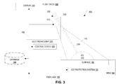
- FIG. 3 is a block diagram schematically depicting operation of a system 300 in accordance with particular examples of the present disclosure appropriate for use in an aircraft 100.
- a light source 240, optical device 230, display 140, and control device 120 are comprised in the fuselage 195 and are communicatively coupled to each other by a communication bus 150.
- a display 140, also connected to the communication bus 150 is comprised in the flight deck 190.
- a wing 180 comprises an ice protection system 130 which is also connected to the communication bus 150.
- the wing 180 also comprises a surface 160 on its leading edge, which is aft of the light source 240 and the optical device 230.
- ice 220 has formed on the surface 160.
- the light source 240 projects a beam 170 of UV-A light through a transparent surface 250 of the fuselage 195, and aftward toward the surface 160.
- the beam 170 causes visible light to be returned from any ice 220 formed on the surface 160, such that light 230 is carried back through the transparent surface 250 and towards the optical device 230.
- the optical device 230 captures images (e.g., photos, video) of the surface 160 and the light 230 from the ice 220.
- the light source 240 is a UV-A/black light. Such a light source 240 may be a commercially available UV-A/black light with a wavelength of 395 nm, for example. In some examples, the light source 240 additionally or alternatively comprises several individual LEDs to produce the beam 170. The LEDs may, in some examples, be combined in a one-inch cylindrical housing. In some examples, the light source 240 is flush-mounted or slightly behind the transparent surface 250, which in some examples is a flush camera lens. In some examples, the beam 170 is aimed at the surface 160 (e.g., a target airfoil surface) from a distance of between 10 to 15 feet, for example.
- the surface 160 e.g., a target airfoil surface
- the beam 170 produced by the light source 240 is produced at an intensity of 100 lumens (e.g., or within 10 lumens thereof). Accordingly, the beam 170 is sufficiently intense given the distance between the light source 240 and the surface 160 to illuminate the surface such that accretion of the ice 220 is discernable from images captured by the optical device 230.
- the transparent surface 250 is a heated lens. In some such examples, the lens is heated electronically. Other examples heat the lens by other means.
- the optical device 230 and transparent surface 250 are comprised in a digital camera. Additionally or alternatively, the optical device 230 and light source 240 are elements comprised in an image capturing system 110, as described above (not shown).
- the optical device 230 is a digital camera installed flush on an inside surface of the fuselage 195 just forward of the light source 240.
- the camera lens is flush with the fuselage 195 and the camera is installed at an angle so that the camera faces through the lens at the surface 160.
- the lens may be electrically heated (e.g., supplied by the same aircraft power source as the UV-A/black light source 240) to prevent the formation of ice or fog on the lens itself that could interfere with the camera view.
- the camera may be focused on the wing leading edge (or other surface of interest) and may provide continuous video or regularly updated still photographic data to control device 120, so that image data may be distinguished from baseline visual characteristics of the surface 160 to determine when color characteristics and/or luminescence changes based on accretion of ice 220 on the surface 160. Accordingly, the system 300 distinguishes between ice 220 and a dry or liquid surface.
- the identification of ice 220 is performed by a comparison of the live photographic images against a database 260, which may be comprised in embedded software of the controller 120.
- an image is output from the optical device 230 to the display 140 in the flight deck 190, e.g., to enable a crew of the aircraft 100 to determine whether icing is present.
- an image is additionally or alternatively sent from the optical device 230 to the control device 120, which is configured (e.g., by software) to determine whether icing is present.
- the control device 120 is configured to transmit a signal to the flight crew.
- the control device 120 is additionally or alternatively configured to activate the ice protection system 130 (e.g., automatically).
- live video or regularly updated still camera images that have been captured by the optical device 230 are sent to the display 140 in the flight deck 190 (e.g., in some examples via the control device 120) so the flight crew can see the surface 160 of the wing 180 and make a decision in accordance with 14 C.F.R. ⁇ 25.1403 relating to illumination and visual ice detection.
- the control device 120 is configured to compare image data captured by the optical device 230 to information comprised in a database 260 to determine whether ice accretion is present, and send an advisory icing signal to alert the flight crew based thereon.
- the database 260 is accessed by the control device 120 via the communication bus 150, as shown in Figure 3 .
- the database 260 is an internal database of the control device 120.
- the control device 120 additionally or alternatively transmits a signal to activate the ice protection control system 130. Such a signal may be transmitted directly to the ice protection control system 130, or to a separate controller that controls the ice protection control system 130 (not shown), which may be located in the wing 180 or the electronics bay 270, for example.
- video or regularly updated still photographic images captured by the optical device 230 are sent to the display 140 where they are made visible to, e.g., the pilot(s) to advise him/her/them of icing conditions, and the pilot(s) would be responsible for activating the ice protection system 130 manually.
- the image data captured by the optical device 230 are analyzed by a control device 120 that is either a dedicated or a federated airplane controller, compared to a database 260 of ice accretion, and a resulting real-time indication of icing conditions is be transmitted to the flight deck 190 (e.g., to the display 140) to alert the crew of the need to activate the ice protection system 130.
- the control device 120 automatically activates the ice protection system 130 to act upon the surface 160.
- control device 120 is, in some examples, an integral part of the image capturing system 110.
- the control device 120 may be housed in a federated controller located elsewhere in the aircraft 100, such as in an electronics bay 270.
- the control device 120 monitors and/or transmits images of the surface 160 that would indicate when ice 220 is present thereon. Images may be transmitted in real-time to the display 140 in the flight deck 190 for crew awareness and action, for example.
- software of the control device 120 may perform logical operations and comparisons of the images to a database 260, and make determinations as to whether ice 220 is present on the surface, and transmit digital signals to the crew, to activate the ice protection system 130, or to another federated ice protection system controller (not shown) which would automatically activate the ice protection system 130.
- the signals are transmitted through the communication bus 150, which may be a physical electrical or optical medium for carrying digital or analog signaling, or an air interface for carrying wireless signals.
- any or all of the elements in the system 300 may be powered by an appropriate power source or combination of power sources (not shown), such as (for example), one or more batteries and/or one or more pneumatic pressure/vacuum sources.
- power sources such as (for example), one or more batteries and/or one or more pneumatic pressure/vacuum sources.
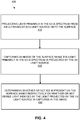
- Figure 4 illustrates an example method 400 of detecting ice 220 on a surface 160.
- the method 400 is implemented by an ice detection system 300.
- the method 400 comprises projecting light primarily in the UV-A spectrum 50 from an ultraviolet (UV) light source 240 onto the surface 160 (block 410), and capturing an image of the surface 160 while the light primarily in the UV-A spectrum 50 is projected by the UV light source 240 (block 420).
- the method 400 further comprises determining whether or not ice 220 is present on the surface 160 based respectively on whether or not visible light induced by the light projected by the UV light source 240 is captured in the image (block 430).
- Figure 5 illustrates a more detailed method 500 of detecting ice 220 on a surface 160.
- initial operation of the system 300 begins when the aircraft 100 is powered up.
- the UV-A/black light source 240 e.g., as part of a larger wing illumination system
- the optical device 230 e.g., digital camera
- Photographic data could be comprised of, e.g., continual video images and/or still photos taken at a constant rate of, for example, one photo per second.
- the image(s) captured are transmitted to the flight deck 190 for observation by the flight crew (block 545).
- the captured image(s) are compared to a database 260 of example images stored within software of the control device 120 (block 520). If the control device 120 determines that no significant color and/or image changes are observed (block 525, no), the method 500 restarts. When the control device 120 determines that an optical change has occurred (block 525, yes), a positive identification of icing conditions is indicated (block 530). Detection signals are transmitted, e.g., via the communication bus 150, to the flight deck 190 to alert the pilots (block 535) and/or to a federated controller of an ice protection system 130 (e.g., in the electronics bay 270) to initiate automatic activation of the appropriate ice protection systems (block 540). The method 500 then ends (block 550).
- the ice detection system 300 is able to detect optical changes in a surface 160 of interest through use of a UV-A/black light source 240, which may be particularly advantageous, e.g., for detecting icing conditions during night operations at any temperature within the 14 CFR 25, Appendix C and Appendix O icing envelopes, thereby meeting the requirements of 14 CFR 25.1403 in addition to any zone of non-detection temperature effects.
- Such a system 300 may be useful, e.g., to future and/or existing commercial transport-category airplanes, including (but not limited to) aircraft 100 similar to the Boeing 737 that do not have an ice detection system and rely solely on the flight crew and visual means for detection of icing conditions.
- the system 300 is more accurate by eliminating the potential zones of non-detection that exist in existing ice detection designs or technologies.
- the system 300 improves important aircraft characteristics such as performance, safety, and/or fuel efficiency by providing the capability for automatic activation of one or more ice protection systems 130.
- the system 300 may be used in a variety of public and private transportation solutions, such as automobiles, trains, buses, etc. In these cases, ice detection may be intended to provide an indication to drivers of inclement or severe weather conditions.
- Figure 6 illustrates an example of the control device 120, according to particular examples of the present disclosure.
- the control device 120 comprises processing circuitry 610 and communication circuitry 630.
- the processing circuitry 610 is communicatively coupled to the communication circuitry 630, e.g., via one or more buses.
- the processing circuitry 610 may comprise one or more microprocessors, microcontrollers, hardware circuits, discrete logic circuits, hardware registers, digital signal processors (DSPs), field-programmable gate arrays (FPGAs), application-specific integrated circuits (ASICs), or a combination thereof.
- DSPs digital signal processors
- FPGAs field-programmable gate arrays
- ASICs application-specific integrated circuits
- the processing circuitry 610 may be programmable hardware capable of executing software instructions 660 stored, e.g., as a machine-readable computer program in memory circuitry 620 of the processing circuitry 610.
- the memory circuitry 620 may comprise any non-transitory machine-readable media known in the art or that may be developed, whether volatile or nonvolatile, including but not limited to solid state media (e.g., SRAM, DRAM, DDRAM, ROM, PROM, EPROM, flash memory, solid state drive, etc.), removable storage devices (e.g., Secure Digital (SD) card, miniSD card, microSD card, memory stick, thumb-drive, USB flash drive, ROM cartridge, Universal Media Disc), fixed drive (e.g., magnetic hard disk drive), or the like, wholly or in any combination.
- solid state media e.g., SRAM, DRAM, DDRAM, ROM, PROM, EPROM, flash memory, solid state drive, etc.
- removable storage devices e.g., Secure Digital (SD)
- the communication circuitry 630 may be a controller hub configured to control the input and output (I/O) data paths of the control device 120. Such I/O data paths may include data paths for exchanging signals over a communication bus 150 and/or air interface.
- the communication circuitry 630 may comprise a transceiver configured to send and receive communication signals over one or more of a cellular network, Ethernet network, or optical network.
- the communication circuitry 630 may be implemented as a unitary physical component, or as a plurality of physical components that are contiguously or separately arranged, any of which may be communicatively coupled to any other, or may communicate with any other via the processing circuitry 610.
- the communication circuitry 630 may comprise output circuitry 640 (e.g., transmitter circuitry configured to send communication signals over the communication bus 150) and input circuitry 650 (e.g., receiver circuitry configured to receive communication signals over the communication bus 150).
- output circuitry 640 e.g., transmitter circuitry configured to send communication signals over the communication bus 150
- input circuitry 650 e.g., receiver circuitry configured to receive communication signals over the communication bus 150
- the processing circuitry 630 is configured to receive an image from an optical device, via the communication circuitry 630, and determine whether or not ice is present on a surface 160 based respectively on whether or not visible light induced by light projected by a UV light source 240 is captured in the image.
- the processing circuitry 630 is further configured to signal an ice protection system 130 communicatively coupled to the control device 120 to deice the surface 160 responsive to the control device 120 detecting that the ice is present.
- the processing circuitry 630 is additionally or alternatively configured to signal a display 140 to annunciate the icing condition to a human operator.
- control device 120 implemented as a plurality of communicatively coupled physical units and/or software modules as illustrated in Figure 7 , e.g., in the processing circuitry 710.
- the control device 120 comprises a receiving unit or module 710 and a determining unit or module 720.
- the receiving unit or module 710 is configured to receive an image from an optical device.
- the determining unit or module 720 is configured to determine whether or not ice is present on a surface 160 based respectively on whether or not visible light induced by light projected by a UV light source 240 is captured in the image.
- control device 120 further comprises an outputting unit or module 730 configured to signal an ice protection system communicatively coupled to the control device 120 to deice the surface 160 responsive to the control device 120 detecting that the ice is present.
- the outputting unit or module 730 is additionally or alternatively configured to signal a display 140 to annunciate the icing condition to a human operator.
- circuits of various examples may be configured in ways that vary in certain details from the broad descriptions given above.
- one or more of the processing functionalities discussed above may be implemented using dedicated hardware, rather than a microprocessor configured with program instructions.
- Such variations, and the engineering tradeoffs associated with each, will be readily appreciated by the skilled practitioner. Since the design and cost tradeoffs for the various hardware approaches, which may depend on system-level requirements that are outside the scope of the present disclosure, are well known to those of ordinary skill in the art, further details of specific hardware implementations are not provided herein.
Landscapes
- Engineering & Computer Science (AREA)
- Computer Vision & Pattern Recognition (AREA)
- Physics & Mathematics (AREA)
- General Physics & Mathematics (AREA)
- Theoretical Computer Science (AREA)
- Quality & Reliability (AREA)
- Aviation & Aerospace Engineering (AREA)
- Investigating Or Analysing Materials By Optical Means (AREA)
- Radiation Pyrometers (AREA)
Abstract
Description
- Throughout aviation history the accumulation of ice on the critical surfaces of aircraft wings has presented an issue. Indeed, a small amount of ice accumulation on the leading edge of an aircraft wing can impact the lift and drag characteristics of a surface. Accordingly, the detection of aircraft icing is common procedure, which is generally required to comply with Federal Aviation Administration (FAA) regulations, such as those within the supercooled liquid water envelopes defined by 14 C.F.R. Part 25, Appendix C and Appendix O.
- Visual identification of icing conditions by the flight crew is sometimes possible, but is typically quite difficult to do while flying at night, when it is dark outside the aircraft, or when visibility is otherwise poor. Although various systems and technologies exist for ice detection on aircraft, the limitations of such systems and technologies often allow ice to form on the leading edge of a wing in the temperature region just below freezing. Because such ice is able to form prior to detection by certain types of ice detection sensors, this temperature region is sometimes referred to as a zone of non-detection.
- Some aircraft, such as the Boeing 737, do not typically have an ice detection system but rely solely on the flight crew and visual means for detection of icing conditions. FAA regulation 14 C.F.R. § 25.1403 specifies a means of determining the presence of ice accretion on aircraft wings during night operations. A typical means for meeting this requirement uses flush-mounted lights installed on the fuselage which are pointed in the direction of the wing leading edge. These lights may use an incandescent or light-emitting diode (LED), visible light source and are intended to project enough light onto the leading edge of the wing to be a visual aid for the flight crew to see the wings. Although these lights improve the ability to see the wings, it is nonetheless often difficult or impractical for the flight crew to detect ice in a timely manner for the activation of aircraft ice protection systems, particularly since ice and the wing surface are often difficult to visually differentiate, e.g., from a distance and/or when the wing is wet.
- Various examples of the present disclosure generally relate to methods, devices, systems, computer readable media, computer program products, carriers, signals, hardware and/or software that detects icing on a surface of a vehicle. Particular examples address a need for a system that provides or enables positive identification of ice, differentiation between an iced surface and a wet or dry surface, and/or automation of the ice detection process. Particular examples herein use ultraviolet wing illumination lights to identify and/or detect ice accretion on aircraft wings so that flight crew may be notified accordingly. Further examples automatically activate the aircraft ice protection systems, e.g., as an aid to flight crew while in flight.
- Further, at least some examples include the use an ultraviolet light source in the UV-A wavelength range of 315 to 400 nanometers (nm) (sometimes known as a UV-A or black light) in the detection of icing on a surface of an aircraft. According to particular examples, this detection is performed in real time on aircraft (e.g., transport-category commercial aircraft), and supports temperatures and conditions within the FAA icing regulations, e.g., 14 C.F.R. Part 25, Appendix C and Appendix O icing envelopes.
- Particular examples of the present disclosure include a system for detecting ice on a surface. The system comprises an ultraviolet (UV) light source configured to project light primarily in the UV-A spectrum onto the surface, an optical device configured to capture an image of the surface while the light primarily in the UV-A spectrum is projected by the UV light source, and a control device communicatively coupled to the optical device. The control device is configured to receive the image from the optical device and determine whether or not ice is present on the surface based respectively on whether or not visible light induced by the light projected by the UV light source is captured in the image.
- In some examples, the control device is further configured to signal an ice protection system communicatively coupled to the control device to deice the surface responsive to the control device detecting that the ice is present.
- In some examples, to determine whether or not ice is present on the surface based respectively on whether or not visible light induced by the light projected by the UV light source is captured in the image, the control device is configured to detect whether or not luminescence is captured in the image.
- In some examples, the UV light source and optical device are mounted on a fuselage of an aircraft and the surface is a surface of an airfoil. In some such examples the surface is aft of the UV light source and optical device on the fuselage.
- In some examples, to determine whether or not ice is present on the surface based respectively on whether or not visible light induced by the light projected by the UV light source is captured in the image, the control device is configured to compare the image to a baseline image of the surface in which ice is not present. In some such examples, to compare the image to the baseline image in which ice is not present on the surface, the control device is configured to compare color characteristics of the image to color characteristics of the baseline image.
- In some examples, to determine whether or not ice is present on the surface based respectively on whether or not visible light induced by the light projected by the UV light source is captured in the image, the control device is configured to determine which of a plurality of stored images most closely resembles the image received from the optical device. In some such examples, the plurality of stored images comprises different images of the surface in which ice is present at different temperatures.
- In some examples, the system further comprises an aircraft on which the UV light source and optical device are mounted, and which comprises the control device.
- Other examples of the present disclosure include an aircraft. The aircraft comprises an ultraviolet (UV) light source configured to project light primarily in the UV-A spectrum onto a surface of the aircraft, an optical device configured to capture an image of the surface while the light primarily in the UV-A spectrum is projected by the UV light source, and a control device communicatively coupled to the optical device. The control device is configured to receive the image from the optical device and determine whether or not ice is present on the surface based respectively on whether or not visible light induced by the light projected by the UV light source is captured in the image.
- In some examples, the control device is further configured to signal an ice protection system communicatively coupled to the control device to deice the surface responsive to the control device determining that the ice is present.
- In some examples, to determine whether or not ice is present on the surface based respectively on whether or not visible light induced by the light projected by the UV light source is captured in the image, the control device is configured to detect whether or not luminescence is captured in the image.
- In some examples, to determine whether or not ice is present on the surface based respectively on whether or not visible light induced by the light projected by the UV light source is captured in the image, the control device is configured to compare the image to a baseline image of the surface in which ice is not present. In some such examples, to compare the image to the baseline image in which ice is not present on the surface, the control device is configured to compare color characteristics of the image to color characteristics of the baseline image.
- In some examples, to determine whether or not ice is present on the surface based respectively on whether or not visible light induced by the light projected by the UV light source is captured in the image, the control device is configured to determine which of a plurality of stored images most closely resembles the image received from the optical device. In some such examples, the plurality of stored images comprises different images of the surface in which ice is present at different temperatures.
- Other examples of the present disclosure include a method, implemented by an ice detection system, of detecting ice on a surface. The method comprises receiving an image of the surface while a light, primarily in the ultraviolet (UV)-A spectrum, is projected onto the surface by a UV light source, and determining whether or not ice is present on the surface based respectively on whether or not visible light induced by the light projected by the UV light source is captured in the image.
- In some examples, the method further comprises projecting, by the UV light source, the light primarily in the UV-A spectrum onto the surface.
- In some examples, receiving the image comprises capturing, by an optical device of the ice detection system, the image of the surface while the light primarily in the UV-A spectrum is projected by the UV light source.
- In some examples, the method further comprises signaling an ice protection system to deice the surface responsive to detecting that the ice is present.
- In some examples, determining whether or not ice is present on the surface based respectively on whether or not visible light induced by the light projected by the UV light source is captured in the image comprises detecting whether or not luminescence is captured in the image.
- In some examples, determining whether or not ice is present on the surface based respectively on whether or not visible light induced by the light projected by the UV light source is captured in the image comprises comparing the image to a baseline image of the surface in which ice is not present. In some such examples, comparing the image to the baseline image in which ice is not present on the surface comprises comparing color characteristics of the image to color characteristics of the baseline image.
- In some examples, determining whether or not ice is present on the surface based respectively on whether or not visible light induced by the light projected by the UV light source is captured in the image comprises determining which of a plurality of stored images most closely resembles the image. In some such examples, the plurality of stored images comprises different images of the surface in which ice is present at different temperatures.
- Other examples include one or more devices, computer program products, configured non-transitory computer-readable mediums, carriers, systems, hardware, software, and/or any combination thereof that are configured to perform any of the methods described herein.
-
-
Figure 1 is a block diagram illustrating an example of the electromagnetic spectrum. -
Figure 2 is a diagram of an example aircraft, according to one or more examples of the present disclosure. -
Figure 3 is a block diagram illustrating an ice detection system, according to one or more examples of the present disclosure. -
Figure 4 is a flow diagram illustrating an example method, according to one or more examples of the present disclosure. -
Figure 5 is a flow diagram illustrating a more detailed example method, according to one or more examples of the present disclosure. -
Figure 6 is a block diagram illustrating an example control device, according to one or more examples of the present disclosure. -
Figure 7 is a block diagram illustrating another example control device, according to one or more examples of the present disclosure. - An example portion of the electromagnetic spectrum 90 is shown in
Figure 1 . The electromagnetic spectrum 90 includes wavelengths in thex-ray spectrum 10, the vacuum-ultraviolet (UV)spectrum 20, the UV-C spectrum 30, the UV-B spectrum 40, the UV-A spectrum 50, thevisible light spectrum 60, and theinfrared spectrum 70, in order of increasing wavelengths. The UV-A spectrum 50 in particular is adjacent to, and includes wavelengths shorter than, thevisible light spectrum 60. Although many black lights produce light throughout theUV range A spectrum 50. That is, the principal wavelength of a black light is within the UV-A range of 315 to 400 nm. - Although UV radiation is invisible to the human eye, illuminating certain materials with UV radiation causes the emission of light in the
visible light spectrum 60, which the human eye perceives as a glow of any of a variety of colors. This glow may be the result of a number of factors, broadly characterized as luminescence, which is the emission of light by a substance not resulting from heat, i.e., a form of cold-body radiation. One type of luminescence is fluorescence, which occurs when light is absorbed and reemitted by a substance, often at a longer wavelength. Another type of luminescence is phosphorescence, which is similar to fluorescence except that the absorbed light energy is stored for a longer period of time before reemission. Yet another type of luminescence is chemiluminescence, which is a process that produces light by virtue of a chemical reaction. Other types of luminescence exist by virtue of other conditions. - Although other types of light sources emit light in the visible light spectrum 60 (which drowns out the glow), black lights are particularly useful for observing luminescence. Examples of the present disclosure use one or more black lights to make formation or accretion of ice on an airfoil or other surface more visible to the human eye and/or detectable by one or more sensors. Because such formation or accretion of ice is a solid, typically white state of water, the glow caused by the use of a black light will differ from that of liquid water and most dry, non-iced surfaces. This glow may be due to one or more forms of luminescence of the ice itself and/or an impurity therein. Other examples include observing a change in color and/or contrast of the surface not caused by luminescence.
-
Figure 2 illustrates anexample aircraft 100 according to examples of the present disclosure. Theaircraft 100 comprises afuselage 195 that forms the main body of theaircraft 100, with aflight deck 190 at the nose and anempennage 185 at the aft. Theaircraft 100 further compriseswings 180 mounted on opposing lateral sides of thefuselage 195. Theaircraft 100 further comprises anengine nacelle 175 mounted under eachwing 180. Although theaircraft 100 in the example ofFigure 2 includes anengine nacelle 175 mounted under eachwing 180,other aircraft 100 consistent with examples of the present disclosure may have no engine nacelles 175 (e.g., as in a glider), asingle engine nacelle 175, oradditional engine nacelles 175. Further, suchother aircraft 100 having one ormore engine nacelles 175 may have the engine nacelle(s) mounted at other locations on theaircraft 100, e.g., such as over thewing 180 or on thefuselage 195, among other positions. - The
aircraft 100 further includes animage capturing system 110 mounted on thefuselage 195. Theimage capturing system 110 comprises a light source that casts abeam 170 of light onto asurface 160 of theaircraft 100. In this example, thesurface 160 is the leading edge of awing 180. As will be discussed in greater detail below, in some examples, theimage capturing system 110 further comprises an optical device, light source, and/or a control device. - According to examples of the present disclosure, the light source is a UV-A light source such that the principal wavelength of the
beam 170 is in the UV-A spectrum 50. In some examples, the light source is a high-intensity flashlight, lamp, laser pointer, or similar light producing device. In some such examples, the light source is collocated with wing illumination lights of the aircraft (not shown). - The aircraft further comprises a
control device 120, anice protection system 130, and adisplay 140 that are communicatively coupled to each other and theimage capturing system 110 by acommunication bus 150. The display, according to this example, is located in theflight deck 190. Theice protection system 130, according to this example, is installed in thewing 180 comprising thesurface 160. In some examples, theice protection system 130 is symmetric on theaircraft 100, such that each of thewings 180 is protected from ice. - The
beam 170 induces visible light from ice formed on thesurface 160, if present, to be returned in a manner that is more readily captured by theimage capturing system 110 and/or the human eye, thereby enabling the detection of ice more quickly and/or more reliably than other, more traditional approaches (e.g., by detecting ice at temperatures just below freezing and/or by more readily distinguishing ice from liquid water and/or a dry surface). Once detected, theice protection system 130 is activated, e.g., earlier and/or more reliably than systems relying on light in thevisible light spectrum 60. - Although
Figure 2 , for purposes of clearly illustrating examples of the present disclosure, illustrates a singleimage capturing system 110 that produces asingle beam 170 onto asingle surface 160 of a wing that is protected by anice protection system 130, theaircraft 100 may include one or more additional or alternative arrangements anywhere on theaircraft 100 to monitor a surface of interest, e.g., on the other lateral side of the aircraft to monitor the opposingwing 180. Indeed, an actual installation would most likely include symmetric left and right-hand systems, both for redundancy and to account for ice accretion uniquely forming on one side or the other due to flight conditions inducing sideslip, etc. Since the UV-A/black light ice detection system may have redundant features on both sides of the airplane, a further advantage allows for one sensor, monitor, or controller detecting ice to activate ice protection systems for both wings (which may be advantageous and/or an aerodynamic requirement). - Further, although the use of one or more UV-A/black lights is shown in
Figure 2 as installed at a location that would also be appropriate for wing illumination lighting, other examples included herein are not limited to the use of UV-A/black lights (i.e., in the wavelength range of 315 to 400 nm), nor are they limited to installation at a typical wing illumination light mounting point of anaircraft 100. Indeed, other examples may be suitable for installation on a variety of vehicles, mounted at a variety of locations, and/or configured to cast light on one or more of a variety of surfaces on which the detection of ice formation is desired. - For example, some examples include ice detection on other aircraft surfaces such as the inlet of an
engine nacelle 175, theempennage 185, and/or other surfaces. Examples also include vehicles other than anaircraft 100, such as a spacecraft, rotorcraft, satellite, rocket, terrestrial vehicle, surface water borne vehicle, sub-surface water borne vehicle, subterranean vehicle, or any combination thereof. In some examples, the vehicle is suitable for commercial, transport, and/or industrial purposes. Further, at least some of the examples include a structure, such as a building designed to house, store, and/or dock one or more such vehicles. In some examples, the structure is a residential, commercial, and/or industrial building. - According to embodiments, the
surface 160 is monitored and/or recorded by theimage capturing system 110, and the resulting images are transmitted (e.g., in real time) to thecontrol device 120, e.g., via thecommunication bus 150. According to examples, thecommunication bus 150 is a physical medium configured to carry optical and/or electrical signals. According to other examples, an air interface configured to carry radio signaling is alternatively used for communication between one or more components. -
Figure 2 illustrates theimage capturing system 110 andcontrol device 120 as separate modules or units. For example, theimage capturing system 110 may be mounted at or near wing illumination lighting on a side of thefuselage 195, whereas thecontrol device 120 may be mounted in an electronics bay within thefuselage 195 orflight deck 190. - Alternatively, the
control device 120 may be comprised in theimage capturing system 110, in some examples. - Examples of the present disclosure enable mitigation of the effects of ice accretion by alerting a flight crew or other personnel to the presence of icing conditions, and/or by transmitting signals to activate the
ice protection system 130 associated with thesurface 160. - Although the ice detection system described herein may be active, e.g., any time vehicle power is available (e.g., regardless of whether day or night operations are being conducted), the UV-A/black light is particularly beneficial during night operations (i.e., when it is generally more difficult to detect ice forming on certain surfaces, like the leading edge of a
wing 180, using the naked eye. -
Figure 3 is a block diagram schematically depicting operation of asystem 300 in accordance with particular examples of the present disclosure appropriate for use in anaircraft 100. As shown inFigure 3 , alight source 240,optical device 230,display 140, andcontrol device 120 are comprised in thefuselage 195 and are communicatively coupled to each other by acommunication bus 150. Adisplay 140, also connected to thecommunication bus 150 is comprised in theflight deck 190. Awing 180 comprises anice protection system 130 which is also connected to thecommunication bus 150. Thewing 180 also comprises asurface 160 on its leading edge, which is aft of thelight source 240 and theoptical device 230. In this example,ice 220 has formed on thesurface 160. - The
light source 240 projects abeam 170 of UV-A light through atransparent surface 250 of thefuselage 195, and aftward toward thesurface 160. Thebeam 170 causes visible light to be returned from anyice 220 formed on thesurface 160, such thatlight 230 is carried back through thetransparent surface 250 and towards theoptical device 230. Theoptical device 230 captures images (e.g., photos, video) of thesurface 160 and the light 230 from theice 220. - The
light source 240 is a UV-A/black light. Such alight source 240 may be a commercially available UV-A/black light with a wavelength of 395 nm, for example. In some examples, thelight source 240 additionally or alternatively comprises several individual LEDs to produce thebeam 170. The LEDs may, in some examples, be combined in a one-inch cylindrical housing. In some examples, thelight source 240 is flush-mounted or slightly behind thetransparent surface 250, which in some examples is a flush camera lens. In some examples, thebeam 170 is aimed at the surface 160 (e.g., a target airfoil surface) from a distance of between 10 to 15 feet, for example. In some examples, thebeam 170 produced by thelight source 240 is produced at an intensity of 100 lumens (e.g., or within 10 lumens thereof). Accordingly, thebeam 170 is sufficiently intense given the distance between thelight source 240 and thesurface 160 to illuminate the surface such that accretion of theice 220 is discernable from images captured by theoptical device 230. - In some examples, the
transparent surface 250 is a heated lens. In some such examples, the lens is heated electronically. Other examples heat the lens by other means. According to other examples, theoptical device 230 andtransparent surface 250 are comprised in a digital camera. Additionally or alternatively, theoptical device 230 andlight source 240 are elements comprised in animage capturing system 110, as described above (not shown). - In some examples, the
optical device 230 is a digital camera installed flush on an inside surface of thefuselage 195 just forward of thelight source 240. In some examples, the camera lens is flush with thefuselage 195 and the camera is installed at an angle so that the camera faces through the lens at thesurface 160. The lens may be electrically heated (e.g., supplied by the same aircraft power source as the UV-A/black light source 240) to prevent the formation of ice or fog on the lens itself that could interfere with the camera view. The camera may be focused on the wing leading edge (or other surface of interest) and may provide continuous video or regularly updated still photographic data to controldevice 120, so that image data may be distinguished from baseline visual characteristics of thesurface 160 to determine when color characteristics and/or luminescence changes based on accretion ofice 220 on thesurface 160. Accordingly, thesystem 300 distinguishes betweenice 220 and a dry or liquid surface. Thus, in some examples, the identification ofice 220 is performed by a comparison of the live photographic images against adatabase 260, which may be comprised in embedded software of thecontroller 120. - One or more of the images captured by the optical device may be used in a variety of ways, according to different examples. In one example, an image is output from the
optical device 230 to thedisplay 140 in theflight deck 190, e.g., to enable a crew of theaircraft 100 to determine whether icing is present. In another example, an image is additionally or alternatively sent from theoptical device 230 to thecontrol device 120, which is configured (e.g., by software) to determine whether icing is present. In response to detecting that icing is present, thecontrol device 120 is configured to transmit a signal to the flight crew. In another example, thecontrol device 120 is additionally or alternatively configured to activate the ice protection system 130 (e.g., automatically). - In one particular example consistent with examples described above, live video or regularly updated still camera images that have been captured by the
optical device 230 are sent to thedisplay 140 in the flight deck 190 (e.g., in some examples via the control device 120) so the flight crew can see thesurface 160 of thewing 180 and make a decision in accordance with 14 C.F.R. § 25.1403 relating to illumination and visual ice detection. In another particular example, thecontrol device 120 is configured to compare image data captured by theoptical device 230 to information comprised in adatabase 260 to determine whether ice accretion is present, and send an advisory icing signal to alert the flight crew based thereon. - In some examples, the
database 260 is accessed by thecontrol device 120 via thecommunication bus 150, as shown inFigure 3 . In other examples, thedatabase 260 is an internal database of thecontrol device 120. In some examples, thecontrol device 120 additionally or alternatively transmits a signal to activate the iceprotection control system 130. Such a signal may be transmitted directly to the iceprotection control system 130, or to a separate controller that controls the ice protection control system 130 (not shown), which may be located in thewing 180 or theelectronics bay 270, for example. In other examples, video or regularly updated still photographic images captured by theoptical device 230 are sent to thedisplay 140 where they are made visible to, e.g., the pilot(s) to advise him/her/them of icing conditions, and the pilot(s) would be responsible for activating theice protection system 130 manually. - According to various examples, the image data captured by the
optical device 230 are analyzed by acontrol device 120 that is either a dedicated or a federated airplane controller, compared to adatabase 260 of ice accretion, and a resulting real-time indication of icing conditions is be transmitted to the flight deck 190 (e.g., to the display 140) to alert the crew of the need to activate theice protection system 130. Alternatively, thecontrol device 120 automatically activates theice protection system 130 to act upon thesurface 160. - Further, as mentioned above, the
control device 120 is, in some examples, an integral part of theimage capturing system 110. Alternatively, thecontrol device 120 may be housed in a federated controller located elsewhere in theaircraft 100, such as in anelectronics bay 270. In some examples, thecontrol device 120 monitors and/or transmits images of thesurface 160 that would indicate whenice 220 is present thereon. Images may be transmitted in real-time to thedisplay 140 in theflight deck 190 for crew awareness and action, for example. Alternatively, software of thecontrol device 120 may perform logical operations and comparisons of the images to adatabase 260, and make determinations as to whetherice 220 is present on the surface, and transmit digital signals to the crew, to activate theice protection system 130, or to another federated ice protection system controller (not shown) which would automatically activate theice protection system 130. In at least some examples, the signals are transmitted through thecommunication bus 150, which may be a physical electrical or optical medium for carrying digital or analog signaling, or an air interface for carrying wireless signals. - Any or all of the elements in the
system 300 may be powered by an appropriate power source or combination of power sources (not shown), such as (for example), one or more batteries and/or one or more pneumatic pressure/vacuum sources. - Consistent with examples described above,
Figure 4 illustrates anexample method 400 of detectingice 220 on asurface 160. Themethod 400 is implemented by anice detection system 300. Themethod 400 comprises projecting light primarily in the UV-A spectrum 50 from an ultraviolet (UV)light source 240 onto the surface 160 (block 410), and capturing an image of thesurface 160 while the light primarily in the UV-A spectrum 50 is projected by the UV light source 240 (block 420). Themethod 400 further comprises determining whether or not ice 220 is present on thesurface 160 based respectively on whether or not visible light induced by the light projected by the UVlight source 240 is captured in the image (block 430). -
Figure 5 illustrates a moredetailed method 500 of detectingice 220 on asurface 160. According to this moredetailed method 500, initial operation of thesystem 300 begins when theaircraft 100 is powered up. The UV-A/black light source 240 (e.g., as part of a larger wing illumination system) is activated to transmit light (block 505) while aircraft power is available and the optical device 230 (e.g., digital camera) visually monitors the wing leadingedge surface 160 in real time for indication of an optical change of the surface 160 (block 510). Photographic data could be comprised of, e.g., continual video images and/or still photos taken at a constant rate of, for example, one photo per second. In some examples, the image(s) captured are transmitted to theflight deck 190 for observation by the flight crew (block 545). - The captured image(s) are compared to a
database 260 of example images stored within software of the control device 120 (block 520). If thecontrol device 120 determines that no significant color and/or image changes are observed (block 525, no), themethod 500 restarts. When thecontrol device 120 determines that an optical change has occurred (block 525, yes), a positive identification of icing conditions is indicated (block 530). Detection signals are transmitted, e.g., via thecommunication bus 150, to theflight deck 190 to alert the pilots (block 535) and/or to a federated controller of an ice protection system 130 (e.g., in the electronics bay 270) to initiate automatic activation of the appropriate ice protection systems (block 540). Themethod 500 then ends (block 550). - Although examples of the present disclosure may be implemented in similar fashion to a wing illumination system architecture, the
ice detection system 300 is able to detect optical changes in asurface 160 of interest through use of a UV-A/black light source 240, which may be particularly advantageous, e.g., for detecting icing conditions during night operations at any temperature within the 14 CFR 25, Appendix C and Appendix O icing envelopes, thereby meeting the requirements of 14 CFR 25.1403 in addition to any zone of non-detection temperature effects. Such asystem 300 may be useful, e.g., to future and/or existing commercial transport-category airplanes, including (but not limited to)aircraft 100 similar to the Boeing 737 that do not have an ice detection system and rely solely on the flight crew and visual means for detection of icing conditions. In some examples, thesystem 300 is more accurate by eliminating the potential zones of non-detection that exist in existing ice detection designs or technologies. In some examples, thesystem 300 improves important aircraft characteristics such as performance, safety, and/or fuel efficiency by providing the capability for automatic activation of one or moreice protection systems 130. Thesystem 300 may be used in a variety of public and private transportation solutions, such as automobiles, trains, buses, etc. In these cases, ice detection may be intended to provide an indication to drivers of inclement or severe weather conditions. - Those skilled in the art will appreciate that the various methods and processes described herein may be implemented using various hardware configurations that generally, but not necessarily, include the use of one or more microprocessors, microcontrollers, digital signal processors, or the like, coupled to memory storing software instructions or data for carrying out the techniques described herein.
- For example,
Figure 6 illustrates an example of thecontrol device 120, according to particular examples of the present disclosure. According to this example, thecontrol device 120 comprisesprocessing circuitry 610 andcommunication circuitry 630. Theprocessing circuitry 610 is communicatively coupled to thecommunication circuitry 630, e.g., via one or more buses. Theprocessing circuitry 610 may comprise one or more microprocessors, microcontrollers, hardware circuits, discrete logic circuits, hardware registers, digital signal processors (DSPs), field-programmable gate arrays (FPGAs), application-specific integrated circuits (ASICs), or a combination thereof. For example, theprocessing circuitry 610 may be programmable hardware capable of executingsoftware instructions 660 stored, e.g., as a machine-readable computer program inmemory circuitry 620 of theprocessing circuitry 610. Thememory circuitry 620, according to various examples, may comprise any non-transitory machine-readable media known in the art or that may be developed, whether volatile or nonvolatile, including but not limited to solid state media (e.g., SRAM, DRAM, DDRAM, ROM, PROM, EPROM, flash memory, solid state drive, etc.), removable storage devices (e.g., Secure Digital (SD) card, miniSD card, microSD card, memory stick, thumb-drive, USB flash drive, ROM cartridge, Universal Media Disc), fixed drive (e.g., magnetic hard disk drive), or the like, wholly or in any combination. - The
communication circuitry 630 may be a controller hub configured to control the input and output (I/O) data paths of thecontrol device 120. Such I/O data paths may include data paths for exchanging signals over acommunication bus 150 and/or air interface. For example, thecommunication circuitry 630 may comprise a transceiver configured to send and receive communication signals over one or more of a cellular network, Ethernet network, or optical network. - The
communication circuitry 630 may be implemented as a unitary physical component, or as a plurality of physical components that are contiguously or separately arranged, any of which may be communicatively coupled to any other, or may communicate with any other via theprocessing circuitry 610. For example, thecommunication circuitry 630 may comprise output circuitry 640 (e.g., transmitter circuitry configured to send communication signals over the communication bus 150) and input circuitry 650 (e.g., receiver circuitry configured to receive communication signals over the communication bus 150). Other examples, permutations, and arrangements of the above and their equivalents will be readily apparent to those of ordinary skill. - According to embodiments of the
control device 120 illustrated inFigure 6 , theprocessing circuitry 630 is configured to receive an image from an optical device, via thecommunication circuitry 630, and determine whether or not ice is present on asurface 160 based respectively on whether or not visible light induced by light projected by aUV light source 240 is captured in the image. In some examples, theprocessing circuitry 630 is further configured to signal anice protection system 130 communicatively coupled to thecontrol device 120 to deice thesurface 160 responsive to thecontrol device 120 detecting that the ice is present. In some examples, theprocessing circuitry 630 is additionally or alternatively configured to signal adisplay 140 to annunciate the icing condition to a human operator. - Other embodiments of the present disclosure include the
control device 120 implemented as a plurality of communicatively coupled physical units and/or software modules as illustrated inFigure 7 , e.g., in theprocessing circuitry 710. According to the example ofFigure 7 , thecontrol device 120 comprises a receiving unit ormodule 710 and a determining unit ormodule 720. The receiving unit ormodule 710 is configured to receive an image from an optical device. The determining unit ormodule 720 is configured to determine whether or not ice is present on asurface 160 based respectively on whether or not visible light induced by light projected by aUV light source 240 is captured in the image. In some examples, thecontrol device 120 further comprises an outputting unit ormodule 730 configured to signal an ice protection system communicatively coupled to thecontrol device 120 to deice thesurface 160 responsive to thecontrol device 120 detecting that the ice is present. In some examples, the outputting unit ormodule 730 is additionally or alternatively configured to signal adisplay 140 to annunciate the icing condition to a human operator. - Those skilled in the art will appreciate that the circuits of various examples may be configured in ways that vary in certain details from the broad descriptions given above. For instance, one or more of the processing functionalities discussed above may be implemented using dedicated hardware, rather than a microprocessor configured with program instructions. Such variations, and the engineering tradeoffs associated with each, will be readily appreciated by the skilled practitioner. Since the design and cost tradeoffs for the various hardware approaches, which may depend on system-level requirements that are outside the scope of the present disclosure, are well known to those of ordinary skill in the art, further details of specific hardware implementations are not provided herein.
- Further, the disclosure comprises examples according to the following clauses:
- Clause A1. A system for detecting ice on a surface, the system comprising:
- an ultraviolet (UV) light source configured to project light in the UV-A spectrum, or primarily in the UV-A spectrum, onto the surface;
- an optical device configured to capture an image of the surface while the light is projected by the UV light source;
- a control device communicatively coupled to the optical device, wherein the control device is configured to receive the image from the optical device and determine whether or not ice is present on the surface based respectively on whether or not visible light induced by the light projected by the UV light source is captured in the image.
- Clause A2. The system of clause A1, wherein the control device is further configured to signal an ice protection system communicatively coupled to the control device to deice the surface responsive to the control device detecting that the ice is present.
- Clause A3. The system of clause A1 or A2, wherein to determine whether or not ice is present on the surface based respectively on whether or not visible light induced by the light projected by the UV light source is captured in the image, the control device is configured to detect whether or not luminescence is captured in the image.
- Clause A4. The system of any of clauses A1 to A3, wherein the UV light source and optical device are mounted on a fuselage of an aircraft and the surface is a surface of an airfoil.
- Clause A5. The system of clause A4, wherein the surface is aft of the UV light source and optical device on the fuselage.
- Clause A6. The system of any of clauses A1 to A5, wherein to determine whether or not ice is present on the surface based respectively on whether or not visible light induced by the light projected by the UV light source is captured in the image, the control device is configured to compare the image to a baseline image of the surface in which ice is not present.
- Clause A7. The system of clause A6, wherein to compare the image to the baseline image in which ice is not present on the surface, the control device is configured to compare color characteristics of the image to color characteristics of the baseline image.
- Clause A8. The system of any of clauses A1 to A7, wherein to determine whether or not ice is present on the surface based respectively on whether or not visible light induced by the light projected by the UV light source is captured in the image, the control device is configured to determine which of a plurality of stored images most closely resembles the image received from the optical device.
- Clause A9. The system of clause A8, wherein the plurality of stored images comprises different images of the surface in which ice is present at different temperatures.
- Clause A10. The system of any of clauses A1 to A9, wherein the system further comprises an aircraft on which the UV light source and optical device are mounted, and which comprises the control device.
- Clause A11. An aircraft comprising:
- an ultraviolet (UV) light source configured to project light in the UV-A spectrum, or primarily in the UV-A spectrum, onto a surface of the aircraft;
- an optical device configured to capture an image of the surface while the light is projected by the UV light source;
- a control device communicatively coupled to the optical device,
wherein the control device is configured to receive the image from the optical device and determine whether or not ice is present on the surface based respectively on whether or not visible light induced by the light projected by the UV light source is captured in the image.
- Clause A12. The aircraft of clause A11, wherein the control device is further configured to signal an ice protection system communicatively coupled to the control device to deice the surface responsive to the control device determining that the ice is present.
- Clause A13. The aircraft of clause A12, wherein to determine whether or not ice is present on the surface based respectively on whether or not visible light induced by the light projected by the UV light source is captured in the image, the control device is configured to detect whether or not luminescence is captured in the image.
- Clause A14. The aircraft of any of clauses A11 to A13, wherein to determine whether or not ice is present on the surface based respectively on whether or not visible light induced by the light projected by the UV light source is captured in the image, the control device is configured to compare the image to a baseline image of the surface in which ice is not present.
- Clause A15. The aircraft of clause A14, wherein to compare the image to the baseline image in which ice is not present on the surface, the control device is configured to compare color characteristics of the image to color characteristics of the baseline image.
- Clause A16. The aircraft of any of clauses A11 to A15, wherein to determine whether or not ice is present on the surface based respectively on whether or not visible light induced by the light projected by the UV light source is captured in the image, the control device is configured to determine which of a plurality of stored images most closely resembles the image received from the optical device.
- Clause A17. The aircraft of clause A16, wherein the plurality of stored images comprises different images of the surface in which ice is present at different temperatures.
- Clause A18. A method, implemented by an ice detection system, of detecting ice on a surface, the method comprising:
- receiving an image of the surface while a light, in the ultraviolet (UV)-A spectrum or primarily in the ultraviolet (UV)-A spectrum, is projected onto the surface by a UV light source;
- determining whether or not ice is present on the surface based respectively on whether or not visible light induced by the light projected by the UV light source is captured in the image.
- Clause A19. The method of clause A18, further comprising projecting, by the UV light source, the light onto the surface.
- Clause A20. The method of clause A18 or A19, wherein receiving the image comprises capturing, by an optical device of the ice detection system, the image of the surface while the light is projected by the UV light source.
- Clause A21. The method of any of clauses A18 to A20, further comprising signaling an ice protection system to deice the surface responsive to detecting that the ice is present.
- Clause A22. The method of any of clauses A18 to A21, wherein determining whether or not ice is present on the surface based respectively on whether or not visible light induced by the light projected by the UV light source is captured in the image comprises detecting whether or not luminescence is captured in the image.
- Clause A23. The method of any of clauses A18 to A22, wherein determining whether or not ice is present on the surface based respectively on whether or not visible light induced by the light projected by the UV light source is captured in the image comprises comparing the image to a baseline image of the surface in which ice is not present.
- Clause A24. The method of clause A23, wherein comparing the image to the baseline image in which ice is not present on the surface comprises comparing color characteristics of the image to color characteristics of the baseline image.
- Clause A25. The method of any of clauses A18 to A24, wherein determining whether or not ice is present on the surface based respectively on whether or not visible light induced by the light projected by the UV light source is captured in the image comprises determining which of a plurality of stored images most closely resembles the image.
- Clause A26. The method of clause A25, wherein the plurality of stored images comprises different images of the surface in which ice is present at different temperatures.
- Clause B1. An aircraft comprising the system of any of clauses A1-A10.
- The present invention may, of course, be carried out in other ways than those specifically set forth herein without departing from essential characteristics of the invention. The present examples are to be considered in all respects as illustrative and not restrictive, and all changes coming within the meaning and equivalency range of the appended claims are intended to be embraced therein. Although steps of various processes or methods described herein may be shown and described as being in a sequence or temporal order, the steps of any such processes or methods are not limited to being carried out in any particular sequence or order, absent an indication otherwise. Indeed, the steps in such processes or methods generally may be carried out in various different sequences and orders while still falling within the scope of the present invention.
Claims (15)
- A system for detecting ice on a surface, the system comprising:an ultraviolet (UV) light source configured to project light primarily in the UV-A spectrum onto the surface;an optical device configured to capture an image of the surface while the light primarily in the UV-A spectrum is projected by the UV light source;a control device communicatively coupled to the optical device, wherein the control device is configured to receive the image from the optical device and determine whether or not ice is present on the surface based respectively on whether or not visible light induced by the light projected by the UV light source is captured in the image.
- The system of claim 1, wherein the control device is further configured to signal an ice protection system communicatively coupled to the control device to deice the surface responsive to the control device detecting that the ice is present.
- The system of claim 1 or 2, wherein to determine whether or not ice is present on the surface based respectively on whether or not visible light induced by the light projected by the UV light source is captured in the image, the control device is configured to detect whether or not luminescence is captured in the image.
- The system of any of claims 1-3, wherein the UV light source and optical device are mounted on a fuselage of an aircraft and the surface is a surface of an airfoil.
- The system of claim 4, wherein the surface is aft of the UV light source and optical device on the fuselage.
- The system of any of claims 1 to 5, wherein to determine whether or not ice is present on the surface based respectively on whether or not visible light induced by the light projected by the UV light source is captured in the image, the control device is configured to compare the image to a baseline image of the surface in which ice is not present.
- The system of claim 6, wherein to compare the image to the baseline image in which ice is not present on the surface, the control device is configured to compare color characteristics of the image to color characteristics of the baseline image.
- The system of any of claims 1 to 7, wherein to determine whether or not ice is present on the surface based respectively on whether or not visible light induced by the light projected by the UV light source is captured in the image, the control device is configured to determine which of a plurality of stored images most closely resembles the image received from the optical device.
- The system of claim 8, wherein the plurality of stored images comprises different images of the surface in which ice is present at different temperatures.
- An aircraft comprising the system of any of claims 1-9.
- A method, implemented by an ice detection system, of detecting ice on a surface, the method comprising:receiving an image of the surface while a light, primarily in the ultraviolet (UV)-A spectrum, is projected onto the surface by a UV light source;determining whether or not ice is present on the surface based respectively on whether or not visible light induced by the light projected by the UV light source is captured in the image.
- The method of claim 11, further comprising projecting, by the UV light source, the light primarily in the UV-A spectrum onto the surface.
- The method of claim 11 or 12, further comprising signaling an ice protection system to deice the surface responsive to detecting that the ice is present.
- The method of any of claims 11-13, wherein determining whether or not ice is present on the surface based respectively on whether or not visible light induced by the light projected by the UV light source is captured in the image comprises comparing the image to a baseline image of the surface in which ice is not present.
- The method of claim 14, wherein comparing the image to the baseline image in which ice is not present on the surface comprises comparing color characteristics of the image to color characteristics of the baseline image.
Applications Claiming Priority (1)
| Application Number | Priority Date | Filing Date | Title |
|---|---|---|---|
| US15/910,799 US10669035B2 (en) | 2018-03-02 | 2018-03-02 | Detecting the presence of ice on a surface using ultraviolet light |
Publications (2)
| Publication Number | Publication Date |
|---|---|
| EP3534330A1 true EP3534330A1 (en) | 2019-09-04 |
| EP3534330B1 EP3534330B1 (en) | 2023-10-18 |
Family
ID=65529413
Family Applications (1)
| Application Number | Title | Priority Date | Filing Date |
|---|---|---|---|
| EP19158333.5A Active EP3534330B1 (en) | 2018-03-02 | 2019-02-20 | Detecting the presence of ice on a surface using ultraviolet light |
Country Status (2)
| Country | Link |
|---|---|
| US (1) | US10669035B2 (en) |
| EP (1) | EP3534330B1 (en) |
Families Citing this family (5)
| Publication number | Priority date | Publication date | Assignee | Title |
|---|---|---|---|---|
| GB2583182B (en) * | 2019-03-11 | 2021-03-10 | Borealis Tech Ltd | System and method for determining aircraft safe taxi, takeoff, and flight readiness |
| GB2587612B (en) * | 2019-09-25 | 2022-05-04 | Rolls Royce Plc | Ice detection system and method |
| CN112966692A (en) * | 2020-12-23 | 2021-06-15 | 中国人民解放军空军工程大学 | Image recognition-based real-time detection method for icing of wings and horizontal tails of airplane |
| US12420935B2 (en) * | 2022-11-30 | 2025-09-23 | The Boeing Company | Aircraft ice detection |
| CN119489959B (en) * | 2023-08-16 | 2026-03-06 | 上海交通大学 | Unmanned aerial vehicles and their intelligent recognition methods for intelligent identification of polar ice fields |
Citations (2)
| Publication number | Priority date | Publication date | Assignee | Title |
|---|---|---|---|---|
| US5039439A (en) * | 1989-03-17 | 1991-08-13 | Massachusetts Institute Of Technology | Optically indicating surface de-icing fluids |
| US20120207589A1 (en) * | 2009-07-23 | 2012-08-16 | Liwas Aps | Detection of ice on airfoils |
Family Cites Families (16)
| Publication number | Priority date | Publication date | Assignee | Title |
|---|---|---|---|---|
| US2371259A (en) * | 1945-03-13 | Device for detecting formation of | ||
| US5180122A (en) * | 1991-05-10 | 1993-01-19 | Fmc Corporation | Apparatus for deicing |
| US5921501A (en) * | 1993-07-14 | 1999-07-13 | Northrop Grumman Corporation | Aircraft ice detecting system |
| US5557261A (en) * | 1994-05-06 | 1996-09-17 | Nichols Research Corporation | Ice monitoring and detection system |
| US6430996B1 (en) * | 1999-11-09 | 2002-08-13 | Mark Anderson | Probe and integrated ice detection and air data system |
| US6425286B1 (en) * | 1999-11-09 | 2002-07-30 | Mark Anderson | Electro-optic ice detection device |
| US6606035B2 (en) * | 2000-11-17 | 2003-08-12 | Safe Landing Systems Inc. | System and method for airport runway monitoring |
| EP2589928B1 (en) * | 2010-07-02 | 2020-10-14 | Commercial Aircraft Corporation Of China Ltd | Detecting device for detecting icing by image and detecting method thereof |
| US9483951B1 (en) * | 2014-06-17 | 2016-11-01 | Rockwell Collins, Inc. | Airborne system and method for detecting and avoiding atmospheric particulates |
| IL237717A (en) * | 2015-03-12 | 2017-04-30 | Elbit Systems Ltd | Detection, characterization and presentation of adverse airborne phenomena |
| JP6361631B2 (en) * | 2015-10-29 | 2018-07-25 | Smk株式会社 | In-vehicle sensor, vehicle lamp, and vehicle |
| US20180079533A1 (en) * | 2016-09-16 | 2018-03-22 | Williams International Co., L.L.C. | Aircraft engine illumination and diagnostic system |
| US20180194487A1 (en) * | 2017-01-09 | 2018-07-12 | General Electric Company | Optical detector for encounter with debris suspension cloud |
| CN110582721B (en) * | 2017-05-01 | 2022-09-20 | 金泰克斯公司 | Imaging device with switchable day and night modes |
| JP6664360B2 (en) * | 2017-09-08 | 2020-03-13 | 本田技研工業株式会社 | Judgment device and vehicle |
| US10934023B2 (en) * | 2017-12-19 | 2021-03-02 | Saishi Frank Li | Image recognition for vehicle safety and damage inspection |
-
2018
- 2018-03-02 US US15/910,799 patent/US10669035B2/en active Active
-
2019
- 2019-02-20 EP EP19158333.5A patent/EP3534330B1/en active Active
Patent Citations (2)
| Publication number | Priority date | Publication date | Assignee | Title |
|---|---|---|---|---|
| US5039439A (en) * | 1989-03-17 | 1991-08-13 | Massachusetts Institute Of Technology | Optically indicating surface de-icing fluids |
| US20120207589A1 (en) * | 2009-07-23 | 2012-08-16 | Liwas Aps | Detection of ice on airfoils |
Non-Patent Citations (2)
| Title |
|---|
| KIRILL M. GERKE ET AL: "Criteria for selecting fluorescent dye tracers for soil hydrological applicationsusing Uranine as an example", JOURNAL OF HYDROLOGY AND HYDROMECHANICS, vol. 61, no. 4, December 2013 (2013-12-01), pages 313 - 325, XP055606219, ISSN: 0042-790X, DOI: 10.2478/johh-2013-0040 * |
| VAUGHAN S. LANGFORD ET AL: "Luminescent Photoproducts in UV-Irradiated Ice", ACCOUNTS OF CHEMICAL RESEARCH., vol. 33, no. 10, October 2000 (2000-10-01), US, pages 665 - 671, XP055606050, ISSN: 0001-4842, DOI: 10.1021/ar990145e * |
Also Published As
| Publication number | Publication date |
|---|---|
| US20190270521A1 (en) | 2019-09-05 |
| EP3534330B1 (en) | 2023-10-18 |
| US10669035B2 (en) | 2020-06-02 |
Similar Documents
| Publication | Publication Date | Title |
|---|---|---|
| EP3534330A1 (en) | Detecting the presence of ice on a surface using ultraviolet light | |
| US20210241638A1 (en) | Runway activity monitoring, logging and analysis for aircraft touchdown detection and abnormal behavior alerting | |
| CN104718134B (en) | The visual signaling of aircraft | |
| US8462354B2 (en) | Aircraft icing detector | |
| CN106482060B (en) | Aircraft exterior lighting device | |
| US6606035B2 (en) | System and method for airport runway monitoring | |
| CN103101626B (en) | Icing detector | |
| CN103043216B (en) | Icing detector | |
| DK2609362T3 (en) | IR aviation warning lights | |
| US20180079533A1 (en) | Aircraft engine illumination and diagnostic system | |
| US11225336B2 (en) | Combined aircraft navigation and anti-collision light, and method of determining a state of erosion of a lens cover of a combined aircraft navigation and anti-collision light | |
| US10214299B2 (en) | Light detection and ranging (LIDAR) ice detection | |
| CN105121284A (en) | anti-icing system | |
| CN109319126A (en) | Manage responses to icing threats | |
| EP2596485A1 (en) | Indicia identifying system | |
| EP3425603B1 (en) | Aircraft-mounted external fire detection system | |
| US11479361B2 (en) | Lighting system for an aircraft with multichannel lens | |
| US11274811B2 (en) | Replaceable light head for exterior aircraft light, and method of evaluating an operating status of an internal power supply of an exterior aircraft light | |
| CN113148220A (en) | Vehicle-mounted airport FOD optical detection system | |
| US12050185B2 (en) | Exterior aircraft light with cover erosion monitoring, aircraft comprising such exterior aircraft light, and method of monitoring erosion of a light transmissive cover | |
| US11690153B2 (en) | Lighting system | |
| US9868546B2 (en) | Dual-mode vehicle light system | |
| CN109649406A (en) | A kind of automatic driving vehicle fault detection method and system | |
| Pralle et al. | High-visibility infrared beacons for IFF and combat ID | |
| FR3149718A1 (en) | Aircraft parking guidance and information system |
Legal Events
| Date | Code | Title | Description |
|---|---|---|---|
| PUAI | Public reference made under article 153(3) epc to a published international application that has entered the european phase |
Free format text: ORIGINAL CODE: 0009012 |
|
| STAA | Information on the status of an ep patent application or granted ep patent |
Free format text: STATUS: REQUEST FOR EXAMINATION WAS MADE |
|
| 17P | Request for examination filed |
Effective date: 20190220 |
|
| AK | Designated contracting states |
Kind code of ref document: A1 Designated state(s): AL AT BE BG CH CY CZ DE DK EE ES FI FR GB GR HR HU IE IS IT LI LT LU LV MC MK MT NL NO PL PT RO RS SE SI SK SM TR |
|
| AX | Request for extension of the european patent |
Extension state: BA ME |
|
| STAA | Information on the status of an ep patent application or granted ep patent |
Free format text: STATUS: EXAMINATION IS IN PROGRESS |
|
| 17Q | First examination report despatched |
Effective date: 20200316 |
|
| RAP3 | Party data changed (applicant data changed or rights of an application transferred) |
Owner name: THE BOEING COMPANY |
|
| GRAP | Despatch of communication of intention to grant a patent |
Free format text: ORIGINAL CODE: EPIDOSNIGR1 |
|
| STAA | Information on the status of an ep patent application or granted ep patent |
Free format text: STATUS: GRANT OF PATENT IS INTENDED |
|
| RIC1 | Information provided on ipc code assigned before grant |
Ipc: B64D 15/22 20060101ALI20230414BHEP Ipc: G06T 7/00 20170101AFI20230414BHEP |
|
| INTG | Intention to grant announced |
Effective date: 20230511 |
|
| P01 | Opt-out of the competence of the unified patent court (upc) registered |
Effective date: 20230612 |
|
| GRAS | Grant fee paid |
Free format text: ORIGINAL CODE: EPIDOSNIGR3 |
|
| GRAA | (expected) grant |
Free format text: ORIGINAL CODE: 0009210 |
|
| STAA | Information on the status of an ep patent application or granted ep patent |
Free format text: STATUS: THE PATENT HAS BEEN GRANTED |
|
| AK | Designated contracting states |
Kind code of ref document: B1 Designated state(s): AL AT BE BG CH CY CZ DE DK EE ES FI FR GB GR HR HU IE IS IT LI LT LU LV MC MK MT NL NO PL PT RO RS SE SI SK SM TR |
|
| REG | Reference to a national code |
Ref country code: GB Ref legal event code: FG4D |
|
| REG | Reference to a national code |
Ref country code: CH Ref legal event code: EP |
|
| REG | Reference to a national code |
Ref country code: IE Ref legal event code: FG4D |
|
| REG | Reference to a national code |
Ref country code: DE Ref legal event code: R096 Ref document number: 602019039445 Country of ref document: DE |
|
| REG | Reference to a national code |
Ref country code: LT Ref legal event code: MG9D |
|
| REG | Reference to a national code |
Ref country code: NL Ref legal event code: MP Effective date: 20231018 |
|
| REG | Reference to a national code |
Ref country code: AT Ref legal event code: MK05 Ref document number: 1623121 Country of ref document: AT Kind code of ref document: T Effective date: 20231018 |
|
| PG25 | Lapsed in a contracting state [announced via postgrant information from national office to epo] |
Ref country code: NL Free format text: LAPSE BECAUSE OF FAILURE TO SUBMIT A TRANSLATION OF THE DESCRIPTION OR TO PAY THE FEE WITHIN THE PRESCRIBED TIME-LIMIT Effective date: 20231018 |
|
| PG25 | Lapsed in a contracting state [announced via postgrant information from national office to epo] |
Ref country code: GR Free format text: LAPSE BECAUSE OF FAILURE TO SUBMIT A TRANSLATION OF THE DESCRIPTION OR TO PAY THE FEE WITHIN THE PRESCRIBED TIME-LIMIT Effective date: 20240119 |
|
| PG25 | Lapsed in a contracting state [announced via postgrant information from national office to epo] |
Ref country code: IS Free format text: LAPSE BECAUSE OF FAILURE TO SUBMIT A TRANSLATION OF THE DESCRIPTION OR TO PAY THE FEE WITHIN THE PRESCRIBED TIME-LIMIT Effective date: 20240218 |
|
| PG25 | Lapsed in a contracting state [announced via postgrant information from national office to epo] |
Ref country code: LT Free format text: LAPSE BECAUSE OF FAILURE TO SUBMIT A TRANSLATION OF THE DESCRIPTION OR TO PAY THE FEE WITHIN THE PRESCRIBED TIME-LIMIT Effective date: 20231018 |
|
| PG25 | Lapsed in a contracting state [announced via postgrant information from national office to epo] |
Ref country code: AT Free format text: LAPSE BECAUSE OF FAILURE TO SUBMIT A TRANSLATION OF THE DESCRIPTION OR TO PAY THE FEE WITHIN THE PRESCRIBED TIME-LIMIT Effective date: 20231018 |
|
| PG25 | Lapsed in a contracting state [announced via postgrant information from national office to epo] |
Ref country code: ES Free format text: LAPSE BECAUSE OF FAILURE TO SUBMIT A TRANSLATION OF THE DESCRIPTION OR TO PAY THE FEE WITHIN THE PRESCRIBED TIME-LIMIT Effective date: 20231018 |
|
| PG25 | Lapsed in a contracting state [announced via postgrant information from national office to epo] |
Ref country code: LT Free format text: LAPSE BECAUSE OF FAILURE TO SUBMIT A TRANSLATION OF THE DESCRIPTION OR TO PAY THE FEE WITHIN THE PRESCRIBED TIME-LIMIT Effective date: 20231018 Ref country code: IS Free format text: LAPSE BECAUSE OF FAILURE TO SUBMIT A TRANSLATION OF THE DESCRIPTION OR TO PAY THE FEE WITHIN THE PRESCRIBED TIME-LIMIT Effective date: 20240218 Ref country code: GR Free format text: LAPSE BECAUSE OF FAILURE TO SUBMIT A TRANSLATION OF THE DESCRIPTION OR TO PAY THE FEE WITHIN THE PRESCRIBED TIME-LIMIT Effective date: 20240119 Ref country code: ES Free format text: LAPSE BECAUSE OF FAILURE TO SUBMIT A TRANSLATION OF THE DESCRIPTION OR TO PAY THE FEE WITHIN THE PRESCRIBED TIME-LIMIT Effective date: 20231018 Ref country code: BG Free format text: LAPSE BECAUSE OF FAILURE TO SUBMIT A TRANSLATION OF THE DESCRIPTION OR TO PAY THE FEE WITHIN THE PRESCRIBED TIME-LIMIT Effective date: 20240118 Ref country code: AT Free format text: LAPSE BECAUSE OF FAILURE TO SUBMIT A TRANSLATION OF THE DESCRIPTION OR TO PAY THE FEE WITHIN THE PRESCRIBED TIME-LIMIT Effective date: 20231018 Ref country code: PT Free format text: LAPSE BECAUSE OF FAILURE TO SUBMIT A TRANSLATION OF THE DESCRIPTION OR TO PAY THE FEE WITHIN THE PRESCRIBED TIME-LIMIT Effective date: 20240219 |
|
| PG25 | Lapsed in a contracting state [announced via postgrant information from national office to epo] |
Ref country code: SE Free format text: LAPSE BECAUSE OF FAILURE TO SUBMIT A TRANSLATION OF THE DESCRIPTION OR TO PAY THE FEE WITHIN THE PRESCRIBED TIME-LIMIT Effective date: 20231018 Ref country code: RS Free format text: LAPSE BECAUSE OF FAILURE TO SUBMIT A TRANSLATION OF THE DESCRIPTION OR TO PAY THE FEE WITHIN THE PRESCRIBED TIME-LIMIT Effective date: 20231018 Ref country code: PL Free format text: LAPSE BECAUSE OF FAILURE TO SUBMIT A TRANSLATION OF THE DESCRIPTION OR TO PAY THE FEE WITHIN THE PRESCRIBED TIME-LIMIT Effective date: 20231018 Ref country code: NO Free format text: LAPSE BECAUSE OF FAILURE TO SUBMIT A TRANSLATION OF THE DESCRIPTION OR TO PAY THE FEE WITHIN THE PRESCRIBED TIME-LIMIT Effective date: 20240118 Ref country code: LV Free format text: LAPSE BECAUSE OF FAILURE TO SUBMIT A TRANSLATION OF THE DESCRIPTION OR TO PAY THE FEE WITHIN THE PRESCRIBED TIME-LIMIT Effective date: 20231018 Ref country code: HR Free format text: LAPSE BECAUSE OF FAILURE TO SUBMIT A TRANSLATION OF THE DESCRIPTION OR TO PAY THE FEE WITHIN THE PRESCRIBED TIME-LIMIT Effective date: 20231018 |
|
| PG25 | Lapsed in a contracting state [announced via postgrant information from national office to epo] |
Ref country code: DK Free format text: LAPSE BECAUSE OF FAILURE TO SUBMIT A TRANSLATION OF THE DESCRIPTION OR TO PAY THE FEE WITHIN THE PRESCRIBED TIME-LIMIT Effective date: 20231018 |
|
| REG | Reference to a national code |
Ref country code: DE Ref legal event code: R097 Ref document number: 602019039445 Country of ref document: DE |
|
| PG25 | Lapsed in a contracting state [announced via postgrant information from national office to epo] |
Ref country code: CZ Free format text: LAPSE BECAUSE OF FAILURE TO SUBMIT A TRANSLATION OF THE DESCRIPTION OR TO PAY THE FEE WITHIN THE PRESCRIBED TIME-LIMIT Effective date: 20231018 |
|
| PG25 | Lapsed in a contracting state [announced via postgrant information from national office to epo] |
Ref country code: SK Free format text: LAPSE BECAUSE OF FAILURE TO SUBMIT A TRANSLATION OF THE DESCRIPTION OR TO PAY THE FEE WITHIN THE PRESCRIBED TIME-LIMIT Effective date: 20231018 |
|
| PG25 | Lapsed in a contracting state [announced via postgrant information from national office to epo] |
Ref country code: SM Free format text: LAPSE BECAUSE OF FAILURE TO SUBMIT A TRANSLATION OF THE DESCRIPTION OR TO PAY THE FEE WITHIN THE PRESCRIBED TIME-LIMIT Effective date: 20231018 Ref country code: SK Free format text: LAPSE BECAUSE OF FAILURE TO SUBMIT A TRANSLATION OF THE DESCRIPTION OR TO PAY THE FEE WITHIN THE PRESCRIBED TIME-LIMIT Effective date: 20231018 Ref country code: RO Free format text: LAPSE BECAUSE OF FAILURE TO SUBMIT A TRANSLATION OF THE DESCRIPTION OR TO PAY THE FEE WITHIN THE PRESCRIBED TIME-LIMIT Effective date: 20231018 Ref country code: IT Free format text: LAPSE BECAUSE OF FAILURE TO SUBMIT A TRANSLATION OF THE DESCRIPTION OR TO PAY THE FEE WITHIN THE PRESCRIBED TIME-LIMIT Effective date: 20231018 Ref country code: EE Free format text: LAPSE BECAUSE OF FAILURE TO SUBMIT A TRANSLATION OF THE DESCRIPTION OR TO PAY THE FEE WITHIN THE PRESCRIBED TIME-LIMIT Effective date: 20231018 Ref country code: DK Free format text: LAPSE BECAUSE OF FAILURE TO SUBMIT A TRANSLATION OF THE DESCRIPTION OR TO PAY THE FEE WITHIN THE PRESCRIBED TIME-LIMIT Effective date: 20231018 Ref country code: CZ Free format text: LAPSE BECAUSE OF FAILURE TO SUBMIT A TRANSLATION OF THE DESCRIPTION OR TO PAY THE FEE WITHIN THE PRESCRIBED TIME-LIMIT Effective date: 20231018 |
|
| PLBE | No opposition filed within time limit |
Free format text: ORIGINAL CODE: 0009261 |
|
| STAA | Information on the status of an ep patent application or granted ep patent |
Free format text: STATUS: NO OPPOSITION FILED WITHIN TIME LIMIT |
|
| 26N | No opposition filed |
Effective date: 20240719 |
|
| PG25 | Lapsed in a contracting state [announced via postgrant information from national office to epo] |
Ref country code: MC Free format text: LAPSE BECAUSE OF FAILURE TO SUBMIT A TRANSLATION OF THE DESCRIPTION OR TO PAY THE FEE WITHIN THE PRESCRIBED TIME-LIMIT Effective date: 20231018 |
|
| REG | Reference to a national code |
Ref country code: CH Ref legal event code: PL |
|
| PG25 | Lapsed in a contracting state [announced via postgrant information from national office to epo] |
Ref country code: LU Free format text: LAPSE BECAUSE OF NON-PAYMENT OF DUE FEES Effective date: 20240220 |
|
| PG25 | Lapsed in a contracting state [announced via postgrant information from national office to epo] |
Ref country code: CH Free format text: LAPSE BECAUSE OF NON-PAYMENT OF DUE FEES Effective date: 20240229 |
|
| PG25 | Lapsed in a contracting state [announced via postgrant information from national office to epo] |
Ref country code: SI Free format text: LAPSE BECAUSE OF FAILURE TO SUBMIT A TRANSLATION OF THE DESCRIPTION OR TO PAY THE FEE WITHIN THE PRESCRIBED TIME-LIMIT Effective date: 20231018 |
|
| PG25 | Lapsed in a contracting state [announced via postgrant information from national office to epo] |
Ref country code: SI Free format text: LAPSE BECAUSE OF FAILURE TO SUBMIT A TRANSLATION OF THE DESCRIPTION OR TO PAY THE FEE WITHIN THE PRESCRIBED TIME-LIMIT Effective date: 20231018 Ref country code: LU Free format text: LAPSE BECAUSE OF NON-PAYMENT OF DUE FEES Effective date: 20240220 Ref country code: CH Free format text: LAPSE BECAUSE OF NON-PAYMENT OF DUE FEES Effective date: 20240229 |
|
| REG | Reference to a national code |
Ref country code: BE Ref legal event code: MM Effective date: 20240229 |
|
| PG25 | Lapsed in a contracting state [announced via postgrant information from national office to epo] |
Ref country code: BE Free format text: LAPSE BECAUSE OF NON-PAYMENT OF DUE FEES Effective date: 20240229 |
|
| PG25 | Lapsed in a contracting state [announced via postgrant information from national office to epo] |
Ref country code: IE Free format text: LAPSE BECAUSE OF NON-PAYMENT OF DUE FEES Effective date: 20240220 |
|
| PG25 | Lapsed in a contracting state [announced via postgrant information from national office to epo] |
Ref country code: IE Free format text: LAPSE BECAUSE OF NON-PAYMENT OF DUE FEES Effective date: 20240220 Ref country code: BE Free format text: LAPSE BECAUSE OF NON-PAYMENT OF DUE FEES Effective date: 20240229 |
|
| PG25 | Lapsed in a contracting state [announced via postgrant information from national office to epo] |
Ref country code: CY Free format text: LAPSE BECAUSE OF FAILURE TO SUBMIT A TRANSLATION OF THE DESCRIPTION OR TO PAY THE FEE WITHIN THE PRESCRIBED TIME-LIMIT; INVALID AB INITIO Effective date: 20190220 |
|
| PG25 | Lapsed in a contracting state [announced via postgrant information from national office to epo] |
Ref country code: HU Free format text: LAPSE BECAUSE OF FAILURE TO SUBMIT A TRANSLATION OF THE DESCRIPTION OR TO PAY THE FEE WITHIN THE PRESCRIBED TIME-LIMIT; INVALID AB INITIO Effective date: 20190220 |
|
| PG25 | Lapsed in a contracting state [announced via postgrant information from national office to epo] |
Ref country code: FI Free format text: LAPSE BECAUSE OF FAILURE TO SUBMIT A TRANSLATION OF THE DESCRIPTION OR TO PAY THE FEE WITHIN THE PRESCRIBED TIME-LIMIT Effective date: 20231019 |
|
| PG25 | Lapsed in a contracting state [announced via postgrant information from national office to epo] |
Ref country code: TR Free format text: LAPSE BECAUSE OF FAILURE TO SUBMIT A TRANSLATION OF THE DESCRIPTION OR TO PAY THE FEE WITHIN THE PRESCRIBED TIME-LIMIT Effective date: 20231018 |
|
| PGFP | Annual fee paid to national office [announced via postgrant information from national office to epo] |
Ref country code: GB Payment date: 20260227 Year of fee payment: 8 |
|
| PGFP | Annual fee paid to national office [announced via postgrant information from national office to epo] |
Ref country code: DE Payment date: 20260227 Year of fee payment: 8 |
|
| PGFP | Annual fee paid to national office [announced via postgrant information from national office to epo] |
Ref country code: FR Payment date: 20260225 Year of fee payment: 8 |