EP3534179A1 - Hybrid position locating system in a manufacturing environment - Google Patents
Hybrid position locating system in a manufacturing environment Download PDFInfo
- Publication number
- EP3534179A1 EP3534179A1 EP19159328.4A EP19159328A EP3534179A1 EP 3534179 A1 EP3534179 A1 EP 3534179A1 EP 19159328 A EP19159328 A EP 19159328A EP 3534179 A1 EP3534179 A1 EP 3534179A1
- Authority
- EP
- European Patent Office
- Prior art keywords
- tool
- laser tracking
- tracking system
- laser
- manufacturing environment
- Prior art date
- Legal status (The legal status is an assumption and is not a legal conclusion. Google has not performed a legal analysis and makes no representation as to the accuracy of the status listed.)
- Pending
Links
Images



Classifications
-
- G—PHYSICS
- G01—MEASURING; TESTING
- G01S—RADIO DIRECTION-FINDING; RADIO NAVIGATION; DETERMINING DISTANCE OR VELOCITY BY USE OF RADIO WAVES; LOCATING OR PRESENCE-DETECTING BY USE OF THE REFLECTION OR RERADIATION OF RADIO WAVES; ANALOGOUS ARRANGEMENTS USING OTHER WAVES
- G01S5/00—Position-fixing by co-ordinating two or more direction or position line determinations; Position-fixing by co-ordinating two or more distance determinations
- G01S5/02—Position-fixing by co-ordinating two or more direction or position line determinations; Position-fixing by co-ordinating two or more distance determinations using radio waves
- G01S5/0257—Hybrid positioning
- G01S5/0263—Hybrid positioning by combining or switching between positions derived from two or more separate positioning systems
- G01S5/0264—Hybrid positioning by combining or switching between positions derived from two or more separate positioning systems at least one of the systems being a non-radio wave positioning system
-
- B—PERFORMING OPERATIONS; TRANSPORTING
- B23—MACHINE TOOLS; METAL-WORKING NOT OTHERWISE PROVIDED FOR
- B23Q—DETAILS, COMPONENTS, OR ACCESSORIES FOR MACHINE TOOLS, e.g. ARRANGEMENTS FOR COPYING OR CONTROLLING; MACHINE TOOLS IN GENERAL CHARACTERISED BY THE CONSTRUCTION OF PARTICULAR DETAILS OR COMPONENTS; COMBINATIONS OR ASSOCIATIONS OF METAL-WORKING MACHINES, NOT DIRECTED TO A PARTICULAR RESULT
- B23Q17/00—Arrangements for observing, indicating or measuring on machine tools
- B23Q17/22—Arrangements for observing, indicating or measuring on machine tools for indicating or measuring existing or desired position of tool or work
-
- B—PERFORMING OPERATIONS; TRANSPORTING
- B64—AIRCRAFT; AVIATION; COSMONAUTICS
- B64F—GROUND OR AIRCRAFT-CARRIER-DECK INSTALLATIONS SPECIALLY ADAPTED FOR USE IN CONNECTION WITH AIRCRAFT; DESIGNING, MANUFACTURING, ASSEMBLING, CLEANING, MAINTAINING OR REPAIRING AIRCRAFT, NOT OTHERWISE PROVIDED FOR; HANDLING, TRANSPORTING, TESTING OR INSPECTING AIRCRAFT COMPONENTS, NOT OTHERWISE PROVIDED FOR
- B64F5/00—Designing, manufacturing, assembling, cleaning, maintaining or repairing aircraft, not otherwise provided for; Handling, transporting, testing or inspecting aircraft components, not otherwise provided for
- B64F5/10—Manufacturing or assembling aircraft, e.g. jigs therefor
-
- B—PERFORMING OPERATIONS; TRANSPORTING
- B64—AIRCRAFT; AVIATION; COSMONAUTICS
- B64F—GROUND OR AIRCRAFT-CARRIER-DECK INSTALLATIONS SPECIALLY ADAPTED FOR USE IN CONNECTION WITH AIRCRAFT; DESIGNING, MANUFACTURING, ASSEMBLING, CLEANING, MAINTAINING OR REPAIRING AIRCRAFT, NOT OTHERWISE PROVIDED FOR; HANDLING, TRANSPORTING, TESTING OR INSPECTING AIRCRAFT COMPONENTS, NOT OTHERWISE PROVIDED FOR
- B64F5/00—Designing, manufacturing, assembling, cleaning, maintaining or repairing aircraft, not otherwise provided for; Handling, transporting, testing or inspecting aircraft components, not otherwise provided for
- B64F5/60—Testing or inspecting aircraft components or systems
-
- G—PHYSICS
- G01—MEASURING; TESTING
- G01B—MEASURING LENGTH, THICKNESS OR SIMILAR LINEAR DIMENSIONS; MEASURING ANGLES; MEASURING AREAS; MEASURING IRREGULARITIES OF SURFACES OR CONTOURS
- G01B11/00—Measuring arrangements characterised by the use of optical techniques
-
- G—PHYSICS
- G01—MEASURING; TESTING
- G01S—RADIO DIRECTION-FINDING; RADIO NAVIGATION; DETERMINING DISTANCE OR VELOCITY BY USE OF RADIO WAVES; LOCATING OR PRESENCE-DETECTING BY USE OF THE REFLECTION OR RERADIATION OF RADIO WAVES; ANALOGOUS ARRANGEMENTS USING OTHER WAVES
- G01S13/00—Systems using the reflection or reradiation of radio waves, e.g. radar systems; Analogous systems using reflection or reradiation of waves whose nature or wavelength is irrelevant or unspecified
- G01S13/74—Systems using reradiation of radio waves, e.g. secondary radar systems; Analogous systems
- G01S13/75—Systems using reradiation of radio waves, e.g. secondary radar systems; Analogous systems using transponders powered from received waves, e.g. using passive transponders, or using passive reflectors
-
- G—PHYSICS
- G01—MEASURING; TESTING
- G01S—RADIO DIRECTION-FINDING; RADIO NAVIGATION; DETERMINING DISTANCE OR VELOCITY BY USE OF RADIO WAVES; LOCATING OR PRESENCE-DETECTING BY USE OF THE REFLECTION OR RERADIATION OF RADIO WAVES; ANALOGOUS ARRANGEMENTS USING OTHER WAVES
- G01S17/00—Systems using the reflection or reradiation of electromagnetic waves other than radio waves, e.g. lidar systems
- G01S17/02—Systems using the reflection of electromagnetic waves other than radio waves
- G01S17/06—Systems determining position data of a target
- G01S17/46—Indirect determination of position data
- G01S17/48—Active triangulation systems, i.e. using the transmission and reflection of electromagnetic waves other than radio waves
-
- G—PHYSICS
- G01—MEASURING; TESTING
- G01S—RADIO DIRECTION-FINDING; RADIO NAVIGATION; DETERMINING DISTANCE OR VELOCITY BY USE OF RADIO WAVES; LOCATING OR PRESENCE-DETECTING BY USE OF THE REFLECTION OR RERADIATION OF RADIO WAVES; ANALOGOUS ARRANGEMENTS USING OTHER WAVES
- G01S17/00—Systems using the reflection or reradiation of electromagnetic waves other than radio waves, e.g. lidar systems
- G01S17/66—Tracking systems using electromagnetic waves other than radio waves
-
- G—PHYSICS
- G01—MEASURING; TESTING
- G01S—RADIO DIRECTION-FINDING; RADIO NAVIGATION; DETERMINING DISTANCE OR VELOCITY BY USE OF RADIO WAVES; LOCATING OR PRESENCE-DETECTING BY USE OF THE REFLECTION OR RERADIATION OF RADIO WAVES; ANALOGOUS ARRANGEMENTS USING OTHER WAVES
- G01S17/00—Systems using the reflection or reradiation of electromagnetic waves other than radio waves, e.g. lidar systems
- G01S17/86—Combinations of lidar systems with systems other than lidar, radar or sonar, e.g. with direction finders
-
- G—PHYSICS
- G01—MEASURING; TESTING
- G01S—RADIO DIRECTION-FINDING; RADIO NAVIGATION; DETERMINING DISTANCE OR VELOCITY BY USE OF RADIO WAVES; LOCATING OR PRESENCE-DETECTING BY USE OF THE REFLECTION OR RERADIATION OF RADIO WAVES; ANALOGOUS ARRANGEMENTS USING OTHER WAVES
- G01S17/00—Systems using the reflection or reradiation of electromagnetic waves other than radio waves, e.g. lidar systems
- G01S17/88—Lidar systems specially adapted for specific applications
-
- G—PHYSICS
- G01—MEASURING; TESTING
- G01S—RADIO DIRECTION-FINDING; RADIO NAVIGATION; DETERMINING DISTANCE OR VELOCITY BY USE OF RADIO WAVES; LOCATING OR PRESENCE-DETECTING BY USE OF THE REFLECTION OR RERADIATION OF RADIO WAVES; ANALOGOUS ARRANGEMENTS USING OTHER WAVES
- G01S17/00—Systems using the reflection or reradiation of electromagnetic waves other than radio waves, e.g. lidar systems
- G01S17/88—Lidar systems specially adapted for specific applications
- G01S17/89—Lidar systems specially adapted for specific applications for mapping or imaging
-
- G—PHYSICS
- G01—MEASURING; TESTING
- G01S—RADIO DIRECTION-FINDING; RADIO NAVIGATION; DETERMINING DISTANCE OR VELOCITY BY USE OF RADIO WAVES; LOCATING OR PRESENCE-DETECTING BY USE OF THE REFLECTION OR RERADIATION OF RADIO WAVES; ANALOGOUS ARRANGEMENTS USING OTHER WAVES
- G01S5/00—Position-fixing by co-ordinating two or more direction or position line determinations; Position-fixing by co-ordinating two or more distance determinations
- G01S5/02—Position-fixing by co-ordinating two or more direction or position line determinations; Position-fixing by co-ordinating two or more distance determinations using radio waves
- G01S5/10—Position of receiver fixed by co-ordinating a plurality of position lines defined by path-difference measurements, e.g. omega or decca systems
-
- G—PHYSICS
- G01—MEASURING; TESTING
- G01S—RADIO DIRECTION-FINDING; RADIO NAVIGATION; DETERMINING DISTANCE OR VELOCITY BY USE OF RADIO WAVES; LOCATING OR PRESENCE-DETECTING BY USE OF THE REFLECTION OR RERADIATION OF RADIO WAVES; ANALOGOUS ARRANGEMENTS USING OTHER WAVES
- G01S5/00—Position-fixing by co-ordinating two or more direction or position line determinations; Position-fixing by co-ordinating two or more distance determinations
- G01S5/02—Position-fixing by co-ordinating two or more direction or position line determinations; Position-fixing by co-ordinating two or more distance determinations using radio waves
- G01S5/14—Determining absolute distances from a plurality of spaced points of known location
-
- G—PHYSICS
- G01—MEASURING; TESTING
- G01S—RADIO DIRECTION-FINDING; RADIO NAVIGATION; DETERMINING DISTANCE OR VELOCITY BY USE OF RADIO WAVES; LOCATING OR PRESENCE-DETECTING BY USE OF THE REFLECTION OR RERADIATION OF RADIO WAVES; ANALOGOUS ARRANGEMENTS USING OTHER WAVES
- G01S7/00—Details of systems according to groups G01S13/00, G01S15/00, G01S17/00
- G01S7/48—Details of systems according to groups G01S13/00, G01S15/00, G01S17/00 of systems according to group G01S17/00
- G01S7/481—Constructional features, e.g. arrangements of optical elements
- G01S7/4817—Constructional features, e.g. arrangements of optical elements relating to scanning
-
- G—PHYSICS
- G05—CONTROLLING; REGULATING
- G05B—CONTROL OR REGULATING SYSTEMS IN GENERAL; FUNCTIONAL ELEMENTS OF SUCH SYSTEMS; MONITORING OR TESTING ARRANGEMENTS FOR SUCH SYSTEMS OR ELEMENTS
- G05B19/00—Program-control systems
-
- G—PHYSICS
- G05—CONTROLLING; REGULATING
- G05B—CONTROL OR REGULATING SYSTEMS IN GENERAL; FUNCTIONAL ELEMENTS OF SUCH SYSTEMS; MONITORING OR TESTING ARRANGEMENTS FOR SUCH SYSTEMS OR ELEMENTS
- G05B19/00—Program-control systems
- G05B19/02—Program-control systems electric
-
- G—PHYSICS
- G05—CONTROLLING; REGULATING
- G05B—CONTROL OR REGULATING SYSTEMS IN GENERAL; FUNCTIONAL ELEMENTS OF SUCH SYSTEMS; MONITORING OR TESTING ARRANGEMENTS FOR SUCH SYSTEMS OR ELEMENTS
- G05B19/00—Program-control systems
- G05B19/02—Program-control systems electric
- G05B19/18—Numerical control [NC], i.e. automatically operating machines, in particular machine tools, e.g. in a manufacturing environment, so as to execute positioning, movement or co-ordinated operations by means of program data in numerical form
-
- G—PHYSICS
- G01—MEASURING; TESTING
- G01S—RADIO DIRECTION-FINDING; RADIO NAVIGATION; DETERMINING DISTANCE OR VELOCITY BY USE OF RADIO WAVES; LOCATING OR PRESENCE-DETECTING BY USE OF THE REFLECTION OR RERADIATION OF RADIO WAVES; ANALOGOUS ARRANGEMENTS USING OTHER WAVES
- G01S2201/00—Indexing scheme relating to beacons or beacon systems transmitting signals capable of being detected by non-directional receivers and defining directions, positions, or position lines fixed relatively to the beacon transmitters
- G01S2201/01—Indexing scheme relating to beacons or beacon systems transmitting signals capable of being detected by non-directional receivers and defining directions, positions, or position lines fixed relatively to the beacon transmitters adapted for specific applications or environments
- G01S2201/03—Construction sites
Definitions
- the present disclosure relates generally to locating an object within a manufacturing environment. More specifically, the present disclosure relates to a cost-effective method of automatically locating an object in a manufacturing environment.
- inspection is performed to verify manufacturing processes on a workpiece. For example, after drilling holes in a workpiece, dimensions of the holes are measured. As another example, after installing fasteners into holes, presence and installation of the fasteners are verified.
- an operator may visually verify the presence of fasteners.
- an operator may use a handheld tool, such as a micrometer, to measure dimensions of a hole.
- Inspection sampling plans may be utilized. Inspection sampling plans selectively inspect a fraction of the items.
- operators When operators perform inspections, operators also identify the item or location inspected. Manual input of the location of the item inspected may be more time-consuming or less accurate than desired. Further, operators identifying sampling locations for inspection sampling plans may be more time-consuming than desired.
- An illustrative aspect of the present disclosure provides a method.
- An operation is performed on a workpiece using a tool.
- the tool is detected within a manufacturing environment using a macro position locator.
- An approximate location of the tool is generated using the macro position locator.
- a refined location of the tool is identified using the approximate location and a micro position locator. Data regarding the operation is associated with the refined location.
- a tool within a manufacturing environment is located using a macro position locator to form an approximate location.
- a refined location is identified using the approximate location, a retro reflective target attached to the tool, and a laser tracking system.
- a further illustrative aspect of the present disclosure provides a hybrid position locating system.
- the hybrid position locating system comprises an ultra-wide band radio frequency tag connected to a tool and a retro reflective target connected to the tool.
- the illustrative aspects recognize and take into account one or more different considerations. For example, the illustrative aspects recognize and take into account that currently work positions during inspection or other operations are not automatically measured. The illustrative aspects recognize and take into account that as a result, performing inspections or other manual operations on a workpiece may have increased operator hours. The illustrative aspects recognize and take into account that further, performing inspections or other manual operation may be less efficient than desired.
- the illustrative aspects recognize and take into account that operators review sampling reports or other work instructions to determine a desired work location and a desired operation.
- the illustrative aspects recognize and take into account that determining work locations on the actual workpiece may be more difficult or more time-consuming than desired.
- the illustrative aspects recognize and take into account that to find a fastener designated to receive inspection, currently operators count the fasteners in a large workpiece to find the work location. For example, an operator may count twenty fasteners up on a large workpiece to locate the fastener to receive an inspection. Likewise, an operator may count a designated number of fasteners from a current inspection location.
- the illustrative aspects recognize and take into account that it would be desirable to have a more efficient method of determining work locations on large workpieces.
- the illustrative aspects recognize and take into account that, currently, operators use mechanical means, such as sticky notes, to mark and preserve work records for subsequent operations.
- the sticky notes may take the form of tape, adhesive backed paper, or any other product that may be adhered to the workpiece.
- the illustrative aspects recognize and take into account that operators may also write notations on the sticky notes to preserve work records.
- the illustrative aspects recognize and take into account that it would be desirable to have centralized records of work locations.
- the illustrative aspects recognize and take into account that conventional laser tracking equipment is undesirably costly.
- the illustrative aspects recognize and take into account that conventional laser tracking equipment may have a higher accuracy than is needed for several operations.
- the illustrative aspects recognize and take into account that a speed of conventional laser tracking systems may be limited by the size of the laser tracking system.
- the illustrative aspects recognize and take into account that conventional laser tracking equipment may effectively hunt within about a square inch.
- the illustrative aspects recognize and take into account that either a broken beam or too large a search area may result in conventional laser tracking equipment "erroring out.”
- the illustrative aspects recognize and take into account that there are several conventional radio frequency technologies such as Wi-Fi, Bluetooth, RFID, or GPS signals that may be used for locating objects.
- the illustrative aspects recognize and take into account that the conventional Wi-Fi, Bluetooth, RFID, or GPS signals may not provide a desired accuracy for manufacturing operations.
- conventional radio frequency technologies may have an accuracy of +/-3 inches or greater.
- the illustrative aspects recognize and take into account that it would be desirable to have a system to provide seamless integration between work measurement location and work management systems.
- the illustrative aspects recognize and take into account that a system would desirably easily integrate into existing portable factory production and quality tools.
- Manufacturing environment 100 includes workpiece 102 to receive operation 104.
- operation 104 is selected from one of inspection operation 106 , fastening operation 108 , drilling operation 110 , and painting operation 112 .
- Performing operation 104 on workpiece 102 generates data 114 .
- Hybrid position locating system 116 is present in manufacturing environment 100 to locate tool 118 within manufacturing environment 100 .
- tool 118 is used to perform operation 104 .
- tool 118 may be a micrometer to perform inspection operation 106 .
- tool 118 may be a drill used to create a hole or install a fastener.
- tool 118 is used to transmit data 114 from operation 104 .
- tool 118 may not be used to perform operation 104 .
- tool 118 may be used only to perform locating processes.
- Hybrid position locating system 116 comprises ultra-wide band radio frequency tag 120 connected to tool 118 and retro reflective target 122 connected to tool 118 .
- Retro reflective target 122 may take any desirable form.
- retro reflective target 122 may take the form of tape or a corner cube.
- ultra-wide band radio frequency tag 120 is part of macro position locator 124 .
- Hybrid position locating system 116 also comprises plurality of ultra-wide band radio frequency anchors 126 at known positions 128 within manufacturing environment 100 .
- Macro position locator 124 locates ultra-wide band radio frequency tag 120 attached to tool 118 within manufacturing environment 100 to form approximate location 130 . Using plurality of ultra-wide band radio frequency anchors 126 and triangulation, approximate location 130 is determined. Macro position locator 124 is desirably fast, but accuracy 132 is not sufficient to locate tool 118 for operation 104 on workpiece 102 . In some illustrative examples, macro position locator 124 has accuracy 132 to within +/- 2.5 inches.
- Ultra-wide band radio frequency tag 120 is located in X, Y, Z coordinates based on the triangulated Radio Frequency (RF) signal strength of plurality of ultra-wide band radio frequency anchors 126 at known positions 128 within manufacturing environment 100.
- Ultra-wide band radio frequency tag 120 and plurality of ultra-wide band radio frequency anchors 126 are relative inexpensive and commercially available.
- ultra-wide band radio frequency tag 120 is equipped with a 3-axis accelerometer, gyroscope, and magnetometer which give the orientation of ultra-wide band radio frequency tag 120 in manufacturing environment 100 .
- each of plurality of ultra-wide band radio frequency anchors 126 is equipped with a 3-axis accelerometer, gyroscope, and magnetometer which give the orientation of the respective radio frequency anchor in manufacturing environment 100 .
- Macro position locator 124 in the form of plurality of ultra-wide band radio frequency anchors 126 and ultra-wide band radio frequency tag 120 has several desirable operating features.
- plurality of ultra-wide band radio frequency anchors 126 and ultra-wide band radio frequency tag 120 form a factory mesh network for cell communications.
- plurality of ultra-wide band radio frequency anchors 126 and ultra-wide band radio frequency tag 120 are low power and battery operable. Battery operable components, such as plurality of ultra-wide band radio frequency anchors 126 and ultra-wide band radio frequency tag 120 , reduce wires in manufacturing environment 100 . Reducing wires in manufacturing environment 100 reduces complexity of movement in manufacturing environment 100.
- the set-up time for macro position locator 124 may also be reduced.
- ultra-wide band radio frequency tag 120 can communicate and can be powered via USB. Additionally, in some illustrative examples, ultra-wide band radio frequency tag 120 can be linked to computer 164 .
- Approximate location 130 is sent to micro position locator 134 to aid in generating a location with greater accuracy than approximate location 130 .
- Micro position locator 134 identifies refined location 136 using approximate location 130.
- Micro position locator 134 has accuracy 138 greater than accuracy 132 of macro position locator 124 .
- micro position locator 134 has accuracy 138 sufficient to distinguish different locations on workpiece 102 to receive operation 104 .
- micro position locator 134 has accuracy 138 to within +/-1 inch.
- micro position locator 134 has accuracy 138 to within +/- 0.5 inch.
- micro position locator 134 has accuracy 138 to within +/- 0.25 inch.
- hybrid position locating system 116 comprises set of laser tracking systems 140 within manufacturing environment 100.
- a “set” of items is one or more items.
- set of laser tracking systems 140 is one or more laser tracking systems.
- set of laser tracking systems 140 has laser tracking system 142 .
- set of laser tracking systems 140 comprises more than one laser tracking system.
- Each laser tracking system of set of laser tracking systems 140 is secured at a respective fixed position in manufacturing environment 100 to form tracking assembly 144 .
- Each respective fixed position in tracking assembly 144 is configured such that set of laser tracking systems 140 provides complete coverage of work area 146 of workpiece 102.
- Work area 146 is an area of workpiece 102 upon which operation 104 will be performed.
- laser tracking system 142 is secured at respective fixed position 148 .
- Respective fixed position 148 is configured such that set of laser tracking systems 140 provides complete coverage of work area 146 of workpiece 102.
- laser tracking system 142 has a 90-degree cone of projection and tracking.
- respective fixed position 148 takes into account the 90-degree cone of projection and tracking.
- set of laser tracking systems 140 is mounted on a scaffolding (not depicted), a building (not depicted), another workpiece (not depicted) within manufacturing environment 100 , work stands (not depicted) at intervals, or any other desirable form of mounting equipment 141 within manufacturing environment 100 to provide complete coverage of work area 146 .
- tracking assembly 144 is battery powered.
- laser tracking system 142 comprises micro mirror 150 configured for laser beam 152 steering.
- laser beam 152 is steered using tracking algorithm 161 associated with laser tracking system 142 .
- Micro mirror 150 may have any desirable size.
- micro mirror 150 is in the range of lmm-3mm in diameter. Steering of laser beam 152 is performed by moving micro mirror 150 .
- micro mirror 150 is a two axis mirror. In some illustrative examples, micro mirror 150 is a scanning two axis (tip-tilt) MEMS mirror. In laser tracking system 142 , micro mirror 150 is implemented as an optical beam-steering (or 2D optical scanning) technology.
- laser beam 152 is steered by micro mirror 150 .
- laser tracking system 142 is used to project image 154 onto workpiece 102 .
- laser tracking system 142 can be commanded wirelessly to project vector graphics, in the form of image 154 , on to workpiece 102 to guide work instructions for operation 104.
- image 154 may take the form of pickup locations or inspection zones for operation 104 .
- image 154 indicates location 156 of workpiece 102 to receive operation 104.
- image 154 may comprise a circle around a fastener of workpiece 102 to receive inspection operation 106 .
- image 154 may comprise a design for painting operation 112 .
- micro mirror 150 can also "track" retro reflective target 122.
- light power detector 158 is part of mirror assembly 159 containing micro mirror 150 .
- light power detector 158 is separate from micro mirror 150 .
- Light power detector 158 detects laser energy 160 reflected from retro reflective target 122.
- refined location 136 of retro reflective target 122 can be computed using angles of micro mirror 150 .
- Laser tracking system 142 initially directs laser beam 152 towards approximate location 130.
- controller 162 is communicatively connected to ultra-wide band radio frequency tag 120 .
- ultra-wide band radio frequency tag 120 transmits approximate location 130
- macro position locator 124 continually operates. In another illustrative example, macro position locator 124 begins operation based on input.
- an operator (not depicted) provides input to macro position locator 124 .
- the input may take the form of the operator pressing a button on tool 118.
- the ultra-wide band radio frequency tag 120 wirelessly signals controller 162 in the laser tracking system 142 to precisely locate retro reflective target 122.
- Ultra-wide band radio frequency tag 120 sends approximate location 130 of tool 118 to laser tracking system 142 which points micro mirror 150 at approximate location 130 and begins a tracking search pattern.
- laser beam 152 strikes retro reflective target 122
- laser energy 160 reflects back to light power detector 158 .
- tracking algorithm 161 of controller 162 locks onto retro reflective target 122.
- Controller 162 computes X, Y, Z coordinates of retro reflective target 122 to form refined location 136.
- controller 162 wirelessly sends refined location 136 to tool 118 for display. In some illustrative examples, controller 162 sends refined location 136 to computer 164 for storage and correlation to data 114 . In some illustrative examples, tool 118 correlates data 114 from operation 104 with refined location 136 . In these illustrative examples, tool 118 sends data 114 and refined location 136 to computer 164 for storage.
- Controller 162 and computer 164 may communicate in any desirable way. Controller 162 and computer 164 may communicate wirelessly or through a wired connection. Controller 162 may send refined location 136 to computer 164 or tool 118 automatically or in response to receiving an input.
- Tool 118 and computer 164 may communicate wirelessly or through a wired connection.
- tool 118 when tool 118 transmits data 114 to computer 164 using a wired communication connection, tool 118 will send data 114 after being connected to computer 164 .
- tool 118 may store data 114 until tool 118 and computer 164 are connected following operation 104. In this example, tool 118 may remain free of wires until after operation 104 is complete.
- workpiece 102 is component 166 of aircraft 168 .
- workpiece 102 may be extremely large, such as a wing or a fuselage.
- set of laser tracking systems 140 may be secured to a portion of aircraft 168.
- set of laser tracking systems 140 may be secured to the interior of the fuselage barrel (not depicted) of aircraft 168.
- tracking assembly 144 would be semi-permanent.
- tracking assembly 144 could be self-checking or calibrating on fixed monuments and /or on fixed targets on aircraft 168 .
- FIG. 1 The illustration of manufacturing environment 100 in Figure 1 is not meant to imply physical or architectural limitations to the manner in which an illustrative aspect may be implemented. Other components in addition to or in place of the ones illustrated may be used. Some components may be unnecessary. Also, the blocks are presented to illustrate some functional components. One or more of these blocks may be combined, divided, or combined and divided into different blocks when implemented in an illustrative aspect.
- set of laser tracking systems 140 may include any desirable quantity of laser tracking systems.
- set of laser tracking systems 140 may include more than just laser tracking system 142 .
- refined location 136 may be determined using triangulation.
- more than one laser tracking system of set of laser tracking systems 140 may direct a respective laser beam at approximate location 130 .
- Each utilized laser tracking system would use a tracking algorithm until the respective laser beam was desirably reflected from retro reflective target 122 , resulting in a respective estimated location for retro reflective target 122 from each utilized laser tracking system.
- refined location 136 is determined.
- any desirable quantity of laser tracking systems from set of laser tracking systems 140 may be used with triangulation.
- each laser tracking system of set of laser tracking systems 140 is used with triangulation.
- only a fraction of set of laser tracking systems 140 is used with triangulation.
- Workpiece 200 is a physical implementation of workpiece 102 of Figure 1 .
- Tool 202 is positioned relative to workpiece 200 in manufacturing environment 204 .
- Tool 202 is a physical implementation of tool 118 of Figure 1 .
- fasteners 206 are present in workpiece 200 .
- Tool 202 is used to perform at least one of: inspecting fasteners 206 or transmitting data related to inspecting fasteners 206 .
- the phrase "at least one of,” when used with a list of items, means different combinations of one or more of the listed items may be used, and only one of each item in the list may be needed. In other words, “at least one of” means any combination of items and number of items may be used from the list, but not all of the items in the list are required.
- the item may be a particular object, a thing, or a category.
- This example also may include item A, item B, and item C, or item B and item C. Of course, any combination of these items may be present. In other examples, "at least one of” may be, for example, without limitation, two of item A, one of item B, and ten of item C; four of item B and seven of item C; or other suitable combinations.
- a subset of fasteners 206 is inspected. This subset may be designated in a work instruction.
- a work instruction (not depicted) includes an operation relative to a fastener of fasteners 206 , it is desirable to locate the respective fastener of fasteners 206 .
- image 208 and image 210 are projected onto workpiece 200 .
- Image 208 and image 210 are representative of work instructions.
- an operator may inspect fastener 212 within image 208.
- an operator may inspect fasteners 214 within image 210 .
- Figure 2 is depicted as involving performing an operation relative to fasteners 206 , this is a non-limiting example. Locating is not limited to operations involving fasteners. In other non-depicted examples, workpiece 200 does not have fasteners 206. In other non-depicted examples, fasteners 206 are present but locating is performed for other portions of workpiece 200 other than fasteners 206 . Locating in the illustrative examples may be performed for any desirable portion of workpiece 200 .
- Macro position locator 300 is a physical implementation of macro position locator 124 of Figure 1 .
- Macro position locator 300 comprises plurality of ultra-wide band radio frequency anchors 302 and ultra-wide band radio frequency tag 304 .
- ultra-wide band radio frequency tag 304 would be connected to the tool (not depicted). To identify an approximate location of the tool, the position of ultra-wide band radio frequency tag 304 is triangulated using plurality of ultra-wide band radio frequency anchors 302 in known locations 308 in manufacturing environment 306 .
- Micro position locator 400 is a physical implementation of micro position locator 134 .
- Micro position locator 400 is configured to determine a refined location of tool 402 using an approximate location provided to micro position locator 400.
- Micro position locator 400 comprises laser tracking system 404 and retro reflective target 406 connected to tool 402 .
- Laser tracking system 404 determines refined location of tool 402 from laser energy reflected by retro reflective target 406 .
- Laser tracking system 404 directs laser beam 408 to the approximate location provided by a macro position locator, such as macro position locator 124 of Figure 1 .
- Laser tracking system 404 then steers laser beam 408 to "hunt" for retro reflective target 406 .
- a micro mirror (not depicted) within laser tracking system 404 is moved. Due to its small size, movement of the micro mirror, and subsequent steering of laser beam 408 is considerably faster than larger conventional laser tracking systems.
- a refined location (not depicted) of retro reflective target 406 can be computed using angles of laser energy 410 .
- the refined location of retro reflective target 406 can be computed using angles of the micro mirror (not depicted).
- Manufacturing environment 500 is a physical implementation of manufacturing environment 100.
- Workpiece 502 is a physical implementation of workpiece 102 in Figure 1 .
- Hybrid position locating system 504 comprises set of laser tracking systems 506.
- Hybrid position locating system 504 is a physical implementation of hybrid position locating system 116 of Figure 1 .
- Each laser tracking system of set of laser tracking systems 506 is secured at a respective fixed position in manufacturing environment 500 to form tracking assembly 508 .
- Each respective fixed position in tracking assembly 508 is configured such that set of laser tracking systems 506 provides complete coverage of work area 510 of workpiece 502 .
- laser tracking system 512 is secured at respective fixed position 514 .
- Coverage 516 of laser tracking system 512 overlaps coverage 518 of laser tracking system 520 .
- Laser tracking system 520 is secured at respective fixed position 522 .
- Coverage 518 of laser tracking system 520 overlaps coverage 524 of laser tracking system 526 .
- Laser tracking system 526 is secured at respective fixed position 528 .
- Each of respective fixed position 514 , respective fixed position 522 , and respective fixed position 528 are selected such that set of laser tracking systems 506 provides complete coverage of work area 510 of workpiece 502 .
- Method 600 may be performed using hybrid position locating system 116 of Figure 1 to locate a position of tool 118 .
- Method 600 may be performed to determine a location of tool 202 of Figure 2 .
- Method 600 may be performed using macro position locator 300 of Figure 3 and micro position locator 400 of Figure 4 .
- Method 600 may be performed in manufacturing environment 500 of Figure 5 .
- Method 600 detects a tool within a manufacturing environment using a macro position locator (operation 602 ).
- Method 600 generates an approximate location of the tool using the macro position locator (operation 604 ).
- Method 600 identifies a refined location of the tool using the approximate location and a micro position locator (operation 606 ). Afterwards, the method terminates.
- method 600 performs an operation on a workpiece using the tool (operation 608 ). In some illustrative examples, method 600 associates data regarding the operation with the refined location (operation 610 ). In some illustrative examples, the operation is selected from one of an inspection operation, a fastening operation, a drilling operation, or a painting operation (operation 612 ).
- detecting the tool within the manufacturing environment using a macro position locator comprises locating an ultra-wide band radio frequency tag on the tool (operation 614 ).
- the macro position locator has an accuracy to within +/- 2.5 inches (operation 616 ).
- the macro position locator does not have sufficient accuracy for identifying the location of many manufacturing operations. Accuracy of +/- 2.5 inches reduces the field of search for the micro position locator. For example, a laser tracking system will search within a smaller region for a retro reflective target.
- the micro position locator has an accuracy to within +/- 1 inch (operation 618 ). In some illustrative examples, the micro position locator has an accuracy to within +/- 0.5 inch.
- the micro position locator provides sufficient accuracy to differentiate different finite locations on a workpiece. For example, the micro position locator provides sufficient accuracy to differentiate between different fastener locations of a workpiece. As another example, the micro position locator provides sufficient accuracy to differentiate between different hole locations in a workpiece.
- identifying a refined location of the tool comprises locating a retro reflective target using a laser tracking system (operation 620 ).
- locating the retro reflective target using a laser tracking system comprises directing a laser beam towards the approximate location using a micro mirror of the laser tracking system (operation 622 ).
- directing the laser beam of the laser tracking system comprises steering the laser beam using a tracking algorithm associated with the laser tracking system (operation 623 ).
- the macro position locator is a laser tracking system
- method 600 projects an image onto the workpiece using the laser tracking system (operation 624 ).
- the workpiece is a component of an aircraft.
- Method 700 may be performed using hybrid position locating system 116 of Figure 1 to locate a position of tool 118. Method 700 may be performed to determine a location of tool 202 of Figure 2 . Method 700 may be performed using macro position locator 300 of Figure 3 and micro position locator 400 of Figure 4 . Method 700 may be performed in manufacturing environment 500 of Figure 5 .
- Method 700 locates a tool within a manufacturing environment using a macro position locator to form an approximate location (operation 702 ).
- Method 700 identifies a refined location using the approximate location, a retro reflective target attached to the tool, and a laser tracking system (operation 704 ). Afterwards, the method terminates.
- method 700 sends the approximate location to a controller for the laser tracking system (operation 706 ). In some illustrative examples, method 700 directs a laser beam of the laser tracking system at the approximate location (operation 708 ). In some illustrative examples, method 700 detects, by the laser tracking system, laser energy reflected from the retro reflective target (operation 710 ).
- directing the laser beam of the laser tracking system comprises steering the laser beam using a micro mirror of the laser tracking system (operation 712 ). In some illustrative examples, directing the laser beam of the laser tracking system comprises steering the laser beam using a tracking algorithm associated with the laser tracking system (operation 713 ). In some illustrative examples, method 700 projects, using the laser tracking system, an image onto a workpiece within the manufacturing environment (operation 714 ).
- locating the tool within the manufacturing environment using the macro position locator comprises locating an ultra-wide band radio frequency tag attached to the tool within the manufacturing environment to form the approximate location (operation 715 ).
- the laser tracking system comprises a controller communicatively connected to the ultra-wide band radio frequency tag (operation 716 ).
- each block in the flowcharts or block diagrams may represent a module, a segment, a function, and/or a portion of an operation or step.
- not all blocks of method 600 or method 700 are performed.
- operations 612 through 624 of Figure 6 are optional.
- operations 706 through 716 of Figure 7 are optional.
- aircraft manufacturing and service method 800 may be described in the context of aircraft manufacturing and service method 800 as shown in Figure 8 and aircraft 900 as shown in Figure 9 .
- Figure 8 an illustration of an aircraft manufacturing and service method is depicted in accordance with an illustrative aspect.
- aircraft manufacturing and service method 800 may include specification and design 802 of aircraft 900 in Figure 9 and material procurement 804 .
- aircraft 900 During production, component and subassembly manufacturing 806 and system integration 808 of aircraft 900 takes place. Thereafter, aircraft 900 may go through certification and delivery 810 in order to be placed in service 812 . While in service 812 by a customer, aircraft 900 is scheduled for routine maintenance and service 814 , which may include modification, reconfiguration, refurbishment, and other maintenance or service.
- Each of the processes of aircraft manufacturing and service method 800 may be performed or carried out by a system integrator, a third party, and/or an operator.
- the operator may be a customer.
- a system integrator may include, without limitation, any number of aircraft manufacturers or major-system subcontractors
- a third party may include, without limitation, any number of vendors, subcontractors, or suppliers
- an operator may be an airline, a leasing company, a military entity, a service organization, and so on.
- aircraft 900 is produced by aircraft manufacturing and service method 800 in Figure 8 and may include airframe 902 with a plurality of systems 904 and interior 906.
- systems 904 include one or more of propulsion system 908 , electrical system 910 , hydraulic system 912 , and environmental system 914 . Any number of other systems may be included.
- propulsion system 908 electrical system 910
- hydraulic system 912 hydraulic system 912
- environmental system 914 any number of other systems may be included.
- Any number of other systems may be included.
- an aerospace example is shown, different illustrative aspects may be applied to other industries, such as the automotive industry.
- Apparatuses and methods embodied herein may be employed during at least one of the stages of aircraft manufacturing and service method 800 .
- One or more illustrative aspects may be used during component and subassembly manufacturing 806 , system integration 808 , or maintenance and service 814 of Figure 8 .
- hybrid position locating system 116 of Figure 1 may be used to determine a position of a tool, such as tool 118 , used to inspect a component during component and subassembly manufacturing 806 .
- hybrid position locating system 116 of Figure 1 may be used to determine a position of a tool, such as tool 118 , used to inspect a portion of aircraft 900 during maintenance and service 814 of Figure 8 .
- Apparatuses and methods embodied herein may be employed in manufacturing at least one component of aircraft 900 .
- hybrid position locating system 116 of Figure 1 may be used to locate a tool during manufacturing of airframe 902 or interior 906 .
Landscapes
- Engineering & Computer Science (AREA)
- Physics & Mathematics (AREA)
- Remote Sensing (AREA)
- Radar, Positioning & Navigation (AREA)
- General Physics & Mathematics (AREA)
- Electromagnetism (AREA)
- Computer Networks & Wireless Communication (AREA)
- Manufacturing & Machinery (AREA)
- Aviation & Aerospace Engineering (AREA)
- Transportation (AREA)
- Automation & Control Theory (AREA)
- Mechanical Engineering (AREA)
- Human Computer Interaction (AREA)
- Length Measuring Devices By Optical Means (AREA)
- Automatic Assembly (AREA)
- Machine Tool Sensing Apparatuses (AREA)
- Control Of Position Or Direction (AREA)
Abstract
Description
- The present disclosure relates generally to locating an object within a manufacturing environment. More specifically, the present disclosure relates to a cost-effective method of automatically locating an object in a manufacturing environment.
- In manufacturing, inspection is performed to verify manufacturing processes on a workpiece. For example, after drilling holes in a workpiece, dimensions of the holes are measured. As another example, after installing fasteners into holes, presence and installation of the fasteners are verified.
- Many inspections of workpieces are performed by operators. For example, an operator may visually verify the presence of fasteners. As another example, an operator may use a handheld tool, such as a micrometer, to measure dimensions of a hole.
- Some workpieces have hundreds or thousands of items to inspect. For workpieces with large quantities of items, inspection sampling plans may be utilized. Inspection sampling plans selectively inspect a fraction of the items.
- When operators perform inspections, operators also identify the item or location inspected. Manual input of the location of the item inspected may be more time-consuming or less accurate than desired. Further, operators identifying sampling locations for inspection sampling plans may be more time-consuming than desired.
- Therefore, it would be desirable to have a method and apparatus that takes into account at least some of the issues discussed above, as well as other possible issues. For example, it would be desirable to provide an apparatus and method for identifying the location of objects within a manufacturing environment in a cost-effective manner.
- An illustrative aspect of the present disclosure provides a method. An operation is performed on a workpiece using a tool. The tool is detected within a manufacturing environment using a macro position locator. An approximate location of the tool is generated using the macro position locator. A refined location of the tool is identified using the approximate location and a micro position locator. Data regarding the operation is associated with the refined location.
- Another illustrative aspect of the present disclosure provides a method. A tool within a manufacturing environment is located using a macro position locator to form an approximate location. A refined location is identified using the approximate location, a retro reflective target attached to the tool, and a laser tracking system.
- A further illustrative aspect of the present disclosure provides a hybrid position locating system. The hybrid position locating system comprises an ultra-wide band radio frequency tag connected to a tool and a retro reflective target connected to the tool.
- The features and functions can be achieved independently in various aspects of the present disclosure or may be combined in yet other aspects in which further details can be seen with reference to the following description and drawings.
- The novel features believed characteristic of the illustrative aspects are set forth in the appended claims. The illustrative aspects, however, as well as a preferred mode of use, further objectives and features thereof, will best be understood by reference to the following detailed description of an illustrative aspect of the present disclosure when read in conjunction with the accompanying drawings, wherein:
-
Figure 1 is an illustration of a block diagram of a manufacturing environment in which a hybrid manufacturing environment position locating system is used to locate a tool in accordance with an illustrative aspect; -
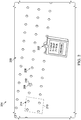
Figure 2 is an illustration of a workpiece with fasteners to be inspected in accordance with an illustrative aspect; -
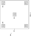
Figure 3 is an illustration of a macro position locator in accordance with an illustrative aspect; -
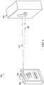
Figure 4 is an illustration of a micro position locator in accordance with an illustrative aspect; -
Figure 5 is an illustration of a manufacturing environment with a hybrid position locating system installed in accordance with an illustrative aspect; -
Figure 6 is an illustration of a flowchart of a method for identifying a position of a tool in accordance with an illustrative aspect; -
Figure 7 is an illustration of a flowchart of a method for identifying a position of a tool in accordance with an illustrative aspect; -
Figure 8 is an illustration of an aircraft manufacturing and service method in the form of a block diagram in accordance with an illustrative aspect; and -
Figure 9 is an illustration of an aircraft in the form of a block diagram in which an illustrative aspect may be implemented. - The illustrative aspects recognize and take into account one or more different considerations. For example, the illustrative aspects recognize and take into account that currently work positions during inspection or other operations are not automatically measured. The illustrative aspects recognize and take into account that as a result, performing inspections or other manual operations on a workpiece may have increased operator hours. The illustrative aspects recognize and take into account that further, performing inspections or other manual operation may be less efficient than desired.
- The illustrative aspects recognize and take into account that operators review sampling reports or other work instructions to determine a desired work location and a desired operation. The illustrative aspects recognize and take into account that determining work locations on the actual workpiece may be more difficult or more time-consuming than desired. For example, the illustrative aspects recognize and take into account that to find a fastener designated to receive inspection, currently operators count the fasteners in a large workpiece to find the work location. For example, an operator may count twenty fasteners up on a large workpiece to locate the fastener to receive an inspection. Likewise, an operator may count a designated number of fasteners from a current inspection location. The illustrative aspects recognize and take into account that it would be desirable to have a more efficient method of determining work locations on large workpieces.
- The illustrative aspects recognize and take into account that, currently, operators use mechanical means, such as sticky notes, to mark and preserve work records for subsequent operations. The sticky notes may take the form of tape, adhesive backed paper, or any other product that may be adhered to the workpiece. The illustrative aspects recognize and take into account that operators may also write notations on the sticky notes to preserve work records. The illustrative aspects recognize and take into account that it would be desirable to have centralized records of work locations.
- The illustrative aspects recognize and take into account that conventional laser tracking equipment is undesirably costly. The illustrative aspects recognize and take into account that conventional laser tracking equipment may have a higher accuracy than is needed for several operations. The illustrative aspects recognize and take into account that a speed of conventional laser tracking systems may be limited by the size of the laser tracking system. The illustrative aspects recognize and take into account that conventional laser tracking equipment may effectively hunt within about a square inch. The illustrative aspects recognize and take into account that either a broken beam or too large a search area may result in conventional laser tracking equipment "erroring out."
- The illustrative aspects recognize and take into account that there are several conventional radio frequency technologies such as Wi-Fi, Bluetooth, RFID, or GPS signals that may be used for locating objects. However, the illustrative aspects recognize and take into account that the conventional Wi-Fi, Bluetooth, RFID, or GPS signals may not provide a desired accuracy for manufacturing operations. For example, illustrative aspects recognize and take into account that conventional radio frequency technologies may have an accuracy of +/-3 inches or greater.
- The illustrative aspects recognize and take into account that it would be desirable to have a system to provide seamless integration between work measurement location and work management systems. The illustrative aspects recognize and take into account that a system would desirably easily integrate into existing portable factory production and quality tools.
- Referring now to the figures and, in particular, with reference to
Figure 1 , an illustration of a block diagram of a manufacturing environment in which a hybrid manufacturing environment position locating system is used to locate a tool is depicted in accordance with an illustrative aspect.Manufacturing environment 100 includesworkpiece 102 to receiveoperation 104. In some illustrative examples,operation 104 is selected from one ofinspection operation 106, fastening operation 108,drilling operation 110, andpainting operation 112. Performingoperation 104 onworkpiece 102 generatesdata 114. - Hybrid
position locating system 116 is present inmanufacturing environment 100 to locatetool 118 withinmanufacturing environment 100. In some illustrative examples,tool 118 is used to performoperation 104. For example,tool 118 may be a micrometer to performinspection operation 106. In another illustrative example,tool 118 may be a drill used to create a hole or install a fastener. In some illustrative examples,tool 118 is used to transmitdata 114 fromoperation 104. In some other illustrative examples,tool 118 may not be used to performoperation 104. In some illustrative examples,tool 118 may be used only to perform locating processes. - Hybrid
position locating system 116 comprises ultra-wide bandradio frequency tag 120 connected totool 118 and retroreflective target 122 connected totool 118. Retroreflective target 122 may take any desirable form. For example, retroreflective target 122 may take the form of tape or a corner cube. As depicted, ultra-wide bandradio frequency tag 120 is part ofmacro position locator 124. Hybridposition locating system 116 also comprises plurality of ultra-wide band radio frequency anchors 126 atknown positions 128 withinmanufacturing environment 100. -
Macro position locator 124 locates ultra-wide bandradio frequency tag 120 attached totool 118 withinmanufacturing environment 100 to formapproximate location 130. Using plurality of ultra-wide band radio frequency anchors 126 and triangulation,approximate location 130 is determined.Macro position locator 124 is desirably fast, butaccuracy 132 is not sufficient to locatetool 118 foroperation 104 onworkpiece 102. In some illustrative examples,macro position locator 124 hasaccuracy 132 to within +/- 2.5 inches. - Ultra-wide band
radio frequency tag 120 is located in X, Y, Z coordinates based on the triangulated Radio Frequency (RF) signal strength of plurality of ultra-wide band radio frequency anchors 126 atknown positions 128 withinmanufacturing environment 100. Ultra-wide bandradio frequency tag 120 and plurality of ultra-wide band radio frequency anchors 126 are relative inexpensive and commercially available. - Although not depicted, in some illustrative examples, ultra-wide band
radio frequency tag 120 is equipped with a 3-axis accelerometer, gyroscope, and magnetometer which give the orientation of ultra-wide bandradio frequency tag 120 inmanufacturing environment 100. Although not depicted, in some illustrative examples, each of plurality of ultra-wide band radio frequency anchors 126 is equipped with a 3-axis accelerometer, gyroscope, and magnetometer which give the orientation of the respective radio frequency anchor inmanufacturing environment 100. -
Macro position locator 124 in the form of plurality of ultra-wide band radio frequency anchors 126 and ultra-wide bandradio frequency tag 120 has several desirable operating features. In some illustrative examples, plurality of ultra-wide band radio frequency anchors 126 and ultra-wide bandradio frequency tag 120 form a factory mesh network for cell communications. Additionally, plurality of ultra-wide band radio frequency anchors 126 and ultra-wide bandradio frequency tag 120 are low power and battery operable. Battery operable components, such as plurality of ultra-wide band radio frequency anchors 126 and ultra-wide bandradio frequency tag 120, reduce wires inmanufacturing environment 100. Reducing wires inmanufacturing environment 100 reduces complexity of movement inmanufacturing environment 100. Whenmacro position locator 124 is wireless, the set-up time formacro position locator 124 may also be reduced. - In some illustrative examples, ultra-wide band
radio frequency tag 120 can communicate and can be powered via USB. Additionally, in some illustrative examples, ultra-wide bandradio frequency tag 120 can be linked tocomputer 164. -
Approximate location 130 is sent tomicro position locator 134 to aid in generating a location with greater accuracy thanapproximate location 130.Micro position locator 134 identifies refinedlocation 136 usingapproximate location 130.Micro position locator 134 hasaccuracy 138 greater thanaccuracy 132 ofmacro position locator 124. In some illustrative examples,micro position locator 134 hasaccuracy 138 sufficient to distinguish different locations onworkpiece 102 to receiveoperation 104. In some illustrative examplesmicro position locator 134 hasaccuracy 138 to within +/-1 inch. In some illustrative examples,micro position locator 134 hasaccuracy 138 to within +/- 0.5 inch. In other illustrative examples,micro position locator 134 hasaccuracy 138 to within +/- 0.25 inch. - In some illustrative examples, hybrid
position locating system 116 comprises set oflaser tracking systems 140 withinmanufacturing environment 100. As used herein, a "set" of items is one or more items. Accordingly, "set oflaser tracking systems 140" is one or more laser tracking systems. As depicted, set oflaser tracking systems 140 has laser tracking system 142. However, in other illustrative examples, set oflaser tracking systems 140 comprises more than one laser tracking system. - Each laser tracking system of set of
laser tracking systems 140 is secured at a respective fixed position inmanufacturing environment 100 to form trackingassembly 144. Each respective fixed position in trackingassembly 144 is configured such that set oflaser tracking systems 140 provides complete coverage ofwork area 146 ofworkpiece 102.Work area 146 is an area ofworkpiece 102 upon whichoperation 104 will be performed. - As depicted, laser tracking system 142 is secured at respective
fixed position 148. Respectivefixed position 148 is configured such that set oflaser tracking systems 140 provides complete coverage ofwork area 146 ofworkpiece 102. In some illustrative examples, laser tracking system 142 has a 90-degree cone of projection and tracking. In these illustrative example, respectivefixed position 148 takes into account the 90-degree cone of projection and tracking. - In some illustrative examples, set of
laser tracking systems 140 is mounted on a scaffolding (not depicted), a building (not depicted), another workpiece (not depicted) withinmanufacturing environment 100, work stands (not depicted) at intervals, or any other desirable form of mountingequipment 141 withinmanufacturing environment 100 to provide complete coverage ofwork area 146. In some illustrative examples, trackingassembly 144 is battery powered. - As depicted, laser tracking system 142 comprises
micro mirror 150 configured forlaser beam 152 steering. In some illustrative examples,laser beam 152 is steered usingtracking algorithm 161 associated with laser tracking system 142.Micro mirror 150 may have any desirable size. In some illustrative examples,micro mirror 150 is in the range of lmm-3mm in diameter. Steering oflaser beam 152 is performed by movingmicro mirror 150. - In some illustrative examples,
micro mirror 150 is a two axis mirror. In some illustrative examples,micro mirror 150 is a scanning two axis (tip-tilt) MEMS mirror. In laser tracking system 142,micro mirror 150 is implemented as an optical beam-steering (or 2D optical scanning) technology. - In this illustrative example,
laser beam 152 is steered bymicro mirror 150. Additionally, laser tracking system 142 is used to projectimage 154 ontoworkpiece 102. In this illustrative example, laser tracking system 142 can be commanded wirelessly to project vector graphics, in the form ofimage 154, on toworkpiece 102 to guide work instructions foroperation 104. For example,image 154 may take the form of pickup locations or inspection zones foroperation 104. - In some illustrative examples,
image 154 indicateslocation 156 ofworkpiece 102 to receiveoperation 104. For example,image 154 may comprise a circle around a fastener ofworkpiece 102 to receiveinspection operation 106. As another example,image 154 may comprise a design forpainting operation 112. - With the presence of
light power detector 158,micro mirror 150 can also "track" retroreflective target 122. In some illustrative examples,light power detector 158 is part of mirror assembly 159 containingmicro mirror 150. In some other illustrative examples,light power detector 158 is separate frommicro mirror 150.Light power detector 158 detectslaser energy 160 reflected from retroreflective target 122. In some illustrative examples,refined location 136 of retroreflective target 122 can be computed using angles ofmicro mirror 150. - Laser tracking system 142 initially directs
laser beam 152 towardsapproximate location 130. In some illustrative examples,controller 162 is communicatively connected to ultra-wide bandradio frequency tag 120. In these illustrative examples, ultra-wide bandradio frequency tag 120 transmitsapproximate location 130 - In one illustrative example,
macro position locator 124 continually operates. In another illustrative example,macro position locator 124 begins operation based on input. - In one illustrative example, an operator (not depicted) provides input to
macro position locator 124. In one illustrative example, the input may take the form of the operator pressing a button ontool 118. After receiving input, the ultra-wide bandradio frequency tag 120 wirelessly signalscontroller 162 in the laser tracking system 142 to precisely locate retroreflective target 122. Ultra-wide bandradio frequency tag 120 sendsapproximate location 130 oftool 118 to laser tracking system 142 which pointsmicro mirror 150 atapproximate location 130 and begins a tracking search pattern. Whenlaser beam 152 strikes retroreflective target 122,laser energy 160 reflects back tolight power detector 158. After receivinglaser energy 160,tracking algorithm 161 ofcontroller 162 locks onto retroreflective target 122.Controller 162 computes X, Y, Z coordinates of retroreflective target 122 to formrefined location 136. - In some illustrative examples,
controller 162 wirelessly sends refinedlocation 136 totool 118 for display. In some illustrative examples,controller 162 sends refinedlocation 136 tocomputer 164 for storage and correlation todata 114. In some illustrative examples,tool 118correlates data 114 fromoperation 104 withrefined location 136. In these illustrative examples,tool 118 sendsdata 114 andrefined location 136 tocomputer 164 for storage. -
Controller 162 andcomputer 164 may communicate in any desirable way.Controller 162 andcomputer 164 may communicate wirelessly or through a wired connection.Controller 162 may sendrefined location 136 tocomputer 164 ortool 118 automatically or in response to receiving an input. -
Tool 118 andcomputer 164 may communicate wirelessly or through a wired connection. In some illustrative examples, whentool 118 transmitsdata 114 tocomputer 164 using a wired communication connection,tool 118 will senddata 114 after being connected tocomputer 164. For example,tool 118 may storedata 114 untiltool 118 andcomputer 164 are connected followingoperation 104. In this example,tool 118 may remain free of wires until afteroperation 104 is complete. - In some illustrative examples,
workpiece 102 iscomponent 166 ofaircraft 168. Whenworkpiece 102 iscomponent 166 ofaircraft 168,workpiece 102 may be extremely large, such as a wing or a fuselage. - When
workpiece 102 iscomponent 166 ofaircraft 168, set oflaser tracking systems 140 may be secured to a portion ofaircraft 168. For example, set oflaser tracking systems 140 may be secured to the interior of the fuselage barrel (not depicted) ofaircraft 168. When set oflaser tracking systems 140 is secured to a portion ofaircraft 168, trackingassembly 144 would be semi-permanent. Additionally, when set oflaser tracking systems 140 is secured to a portion ofaircraft 168, trackingassembly 144 could be self-checking or calibrating on fixed monuments and /or on fixed targets onaircraft 168. - The illustration of
manufacturing environment 100 inFigure 1 is not meant to imply physical or architectural limitations to the manner in which an illustrative aspect may be implemented. Other components in addition to or in place of the ones illustrated may be used. Some components may be unnecessary. Also, the blocks are presented to illustrate some functional components. One or more of these blocks may be combined, divided, or combined and divided into different blocks when implemented in an illustrative aspect. - For example, set of
laser tracking systems 140 may include any desirable quantity of laser tracking systems. In some illustrative examples, set oflaser tracking systems 140 may include more than just laser tracking system 142. - In some illustrative examples, when set of
laser tracking systems 140 contains more than one laser tracking system,refined location 136 may be determined using triangulation. For example, more than one laser tracking system of set oflaser tracking systems 140 may direct a respective laser beam atapproximate location 130. Each utilized laser tracking system would use a tracking algorithm until the respective laser beam was desirably reflected from retroreflective target 122, resulting in a respective estimated location for retroreflective target 122 from each utilized laser tracking system. Using the respective estimated locations provided by each of the utilized laser tracking systems and triangulation,refined location 136 is determined. - Any desirable quantity of laser tracking systems from set of
laser tracking systems 140 may be used with triangulation. In some illustrative examples, each laser tracking system of set oflaser tracking systems 140 is used with triangulation. In some illustrative examples, only a fraction of set oflaser tracking systems 140 is used with triangulation. - Turning now to
Figure 2 , an illustration of a workpiece with fasteners to be inspected is depicted in accordance with an illustrative aspect.Workpiece 200 is a physical implementation ofworkpiece 102 ofFigure 1 .Tool 202 is positioned relative toworkpiece 200 inmanufacturing environment 204.Tool 202 is a physical implementation oftool 118 ofFigure 1 . - As depicted,
fasteners 206 are present inworkpiece 200. In some illustrative examples, it is desired to inspectfasteners 206.Tool 202 is used to perform at least one of: inspectingfasteners 206 or transmitting data related to inspectingfasteners 206. - As used herein, the phrase "at least one of," when used with a list of items, means different combinations of one or more of the listed items may be used, and only one of each item in the list may be needed. In other words, "at least one of" means any combination of items and number of items may be used from the list, but not all of the items in the list are required. The item may be a particular object, a thing, or a category.
- This example also may include item A, item B, and item C, or item B and item C. Of course, any combination of these items may be present. In other examples, "at least one of" may be, for example, without limitation, two of item A, one of item B, and ten of item C; four of item B and seven of item C; or other suitable combinations.
- In some illustrative examples, a subset of
fasteners 206 is inspected. This subset may be designated in a work instruction. When a work instruction (not depicted) includes an operation relative to a fastener offasteners 206, it is desirable to locate the respective fastener offasteners 206. - As depicted,
image 208 andimage 210 are projected ontoworkpiece 200.Image 208 andimage 210 are representative of work instructions. For example, an operator may inspectfastener 212 withinimage 208. As another example, an operator may inspectfasteners 214 withinimage 210. - Although
Figure 2 is depicted as involving performing an operation relative tofasteners 206, this is a non-limiting example. Locating is not limited to operations involving fasteners. In other non-depicted examples,workpiece 200 does not havefasteners 206. In other non-depicted examples,fasteners 206 are present but locating is performed for other portions ofworkpiece 200 other thanfasteners 206. Locating in the illustrative examples may be performed for any desirable portion ofworkpiece 200. - Turning now to
Figure 3 , an illustration of a macro position locator is depicted in accordance with an illustrative aspect.Macro position locator 300 is a physical implementation ofmacro position locator 124 ofFigure 1 .Macro position locator 300 comprises plurality of ultra-wide band radio frequency anchors 302 and ultra-wide bandradio frequency tag 304. - To identify an approximate location of a tool in
manufacturing environment 306, ultra-wide bandradio frequency tag 304 would be connected to the tool (not depicted). To identify an approximate location of the tool, the position of ultra-wide bandradio frequency tag 304 is triangulated using plurality of ultra-wide band radio frequency anchors 302 in knownlocations 308 inmanufacturing environment 306. - Turning now to
Figure 4 , an illustration of a micro position locator is depicted in accordance with an illustrative aspect.Micro position locator 400 is a physical implementation ofmicro position locator 134.Micro position locator 400 is configured to determine a refined location oftool 402 using an approximate location provided tomicro position locator 400. -
Micro position locator 400 compriseslaser tracking system 404 and retroreflective target 406 connected totool 402.Laser tracking system 404 determines refined location oftool 402 from laser energy reflected by retroreflective target 406. -
Laser tracking system 404 directslaser beam 408 to the approximate location provided by a macro position locator, such asmacro position locator 124 ofFigure 1 .Laser tracking system 404 then steerslaser beam 408 to "hunt" for retroreflective target 406. To steerlaser beam 408, a micro mirror (not depicted) withinlaser tracking system 404 is moved. Due to its small size, movement of the micro mirror, and subsequent steering oflaser beam 408 is considerably faster than larger conventional laser tracking systems. - When
laser beam 408 strikes retroreflective target 406,laser energy 410 is reflected.Laser tracking system 404 detectslaser energy 410 reflected from retroreflective target 406. In some illustrative examples, a refined location (not depicted) of retroreflective target 406 can be computed using angles oflaser energy 410. In some illustrative examples, the refined location of retroreflective target 406 can be computed using angles of the micro mirror (not depicted). - Turning now to
Figure 5 , an illustration of a manufacturing environment with a hybrid position locating system installed is depicted in accordance with an illustrative aspect.Manufacturing environment 500 is a physical implementation ofmanufacturing environment 100.Workpiece 502 is a physical implementation ofworkpiece 102 inFigure 1 . Hybridposition locating system 504 comprises set oflaser tracking systems 506. Hybridposition locating system 504 is a physical implementation of hybridposition locating system 116 ofFigure 1 . - Each laser tracking system of set of
laser tracking systems 506 is secured at a respective fixed position inmanufacturing environment 500 to form trackingassembly 508. Each respective fixed position in trackingassembly 508 is configured such that set oflaser tracking systems 506 provides complete coverage ofwork area 510 ofworkpiece 502. - For example,
laser tracking system 512 is secured at respectivefixed position 514.Coverage 516 oflaser tracking system 512 overlapscoverage 518 oflaser tracking system 520.Laser tracking system 520 is secured at respectivefixed position 522.Coverage 518 oflaser tracking system 520 overlapscoverage 524 oflaser tracking system 526.Laser tracking system 526 is secured at respectivefixed position 528. Each of respectivefixed position 514, respectivefixed position 522, and respectivefixed position 528 are selected such that set oflaser tracking systems 506 provides complete coverage ofwork area 510 ofworkpiece 502. - Turning now to
Figure 6 , an illustration of a flowchart of a method for identifying a position of a tool is depicted in accordance with an illustrative aspect.Method 600 may be performed using hybridposition locating system 116 ofFigure 1 to locate a position oftool 118.Method 600 may be performed to determine a location oftool 202 ofFigure 2 .Method 600 may be performed usingmacro position locator 300 ofFigure 3 andmicro position locator 400 ofFigure 4 .Method 600 may be performed inmanufacturing environment 500 ofFigure 5 . -
Method 600 detects a tool within a manufacturing environment using a macro position locator (operation 602).Method 600 generates an approximate location of the tool using the macro position locator (operation 604).Method 600 identifies a refined location of the tool using the approximate location and a micro position locator (operation 606). Afterwards, the method terminates. - In some illustrative examples,
method 600 performs an operation on a workpiece using the tool (operation 608). In some illustrative examples,method 600 associates data regarding the operation with the refined location (operation 610). In some illustrative examples, the operation is selected from one of an inspection operation, a fastening operation, a drilling operation, or a painting operation (operation 612). - In some illustrative examples, detecting the tool within the manufacturing environment using a macro position locator comprises locating an ultra-wide band radio frequency tag on the tool (operation 614). In some illustrative examples, the macro position locator has an accuracy to within +/- 2.5 inches (operation 616). The macro position locator does not have sufficient accuracy for identifying the location of many manufacturing operations. Accuracy of +/- 2.5 inches reduces the field of search for the micro position locator. For example, a laser tracking system will search within a smaller region for a retro reflective target.
- In some illustrative examples, the micro position locator has an accuracy to within +/- 1 inch (operation 618). In some illustrative examples, the micro position locator has an accuracy to within +/- 0.5 inch. The micro position locator provides sufficient accuracy to differentiate different finite locations on a workpiece. For example, the micro position locator provides sufficient accuracy to differentiate between different fastener locations of a workpiece. As another example, the micro position locator provides sufficient accuracy to differentiate between different hole locations in a workpiece.
- In some illustrative examples, identifying a refined location of the tool comprises locating a retro reflective target using a laser tracking system (operation 620). In some illustrative examples, locating the retro reflective target using a laser tracking system comprises directing a laser beam towards the approximate location using a micro mirror of the laser tracking system (operation 622). In some illustrative examples, directing the laser beam of the laser tracking system comprises steering the laser beam using a tracking algorithm associated with the laser tracking system (operation 623).
- In some illustrative examples the macro position locator is a laser tracking system, and
method 600 projects an image onto the workpiece using the laser tracking system (operation 624). In some illustrative examples, the workpiece is a component of an aircraft. - Turning now to
Figure 7 , an illustration of a flowchart of a method for identifying a position of a tool is depicted in accordance with an illustrative aspect.Method 700 may be performed using hybridposition locating system 116 ofFigure 1 to locate a position oftool 118.Method 700 may be performed to determine a location oftool 202 ofFigure 2 .Method 700 may be performed usingmacro position locator 300 ofFigure 3 andmicro position locator 400 ofFigure 4 .Method 700 may be performed inmanufacturing environment 500 ofFigure 5 . -
Method 700 locates a tool within a manufacturing environment using a macro position locator to form an approximate location (operation 702).Method 700 identifies a refined location using the approximate location, a retro reflective target attached to the tool, and a laser tracking system (operation 704). Afterwards, the method terminates. - In some illustrative examples,
method 700 sends the approximate location to a controller for the laser tracking system (operation 706). In some illustrative examples,method 700 directs a laser beam of the laser tracking system at the approximate location (operation 708). In some illustrative examples,method 700 detects, by the laser tracking system, laser energy reflected from the retro reflective target (operation 710). - In some illustrative examples, directing the laser beam of the laser tracking system comprises steering the laser beam using a micro mirror of the laser tracking system (operation 712). In some illustrative examples, directing the laser beam of the laser tracking system comprises steering the laser beam using a tracking algorithm associated with the laser tracking system (operation 713). In some illustrative examples,
method 700 projects, using the laser tracking system, an image onto a workpiece within the manufacturing environment (operation 714). - In some illustrative examples, locating the tool within the manufacturing environment using the macro position locator comprises locating an ultra-wide band radio frequency tag attached to the tool within the manufacturing environment to form the approximate location (operation 715). In some illustrative examples, the laser tracking system comprises a controller communicatively connected to the ultra-wide band radio frequency tag (operation 716).
- The flowcharts and block diagrams in the different depicted aspects illustrate the architecture, functionality, and operation of some possible implementations of apparatus and methods in an illustrative aspect. In this regard, each block in the flowcharts or block diagrams may represent a module, a segment, a function, and/or a portion of an operation or step.
- In some alternative implementations of an illustrative aspect, the function or functions noted in the blocks may occur out of the order noted in the figures. For example, in some cases, two blocks shown in succession may be executed substantially concurrently, or the blocks may sometimes be performed in the reverse order, depending upon the functionality involved. Also, other blocks may be added, in addition to the illustrated blocks, in a flowchart or block diagram.
- In some illustrative examples, not all blocks of
method 600 ormethod 700 are performed. For example,operations 612 through 624 ofFigure 6 are optional. As another example,operations 706 through 716 ofFigure 7 are optional. - The illustrative aspects of the present disclosure may be described in the context of aircraft manufacturing and
service method 800 as shown inFigure 8 andaircraft 900 as shown inFigure 9 . Turning first toFigure 8 , an illustration of an aircraft manufacturing and service method is depicted in accordance with an illustrative aspect. During pre-production, aircraft manufacturing andservice method 800 may include specification anddesign 802 ofaircraft 900 inFigure 9 andmaterial procurement 804. - During production, component and
subassembly manufacturing 806 andsystem integration 808 ofaircraft 900 takes place. Thereafter,aircraft 900 may go through certification anddelivery 810 in order to be placed inservice 812. While inservice 812 by a customer,aircraft 900 is scheduled for routine maintenance andservice 814, which may include modification, reconfiguration, refurbishment, and other maintenance or service. - Each of the processes of aircraft manufacturing and
service method 800 may be performed or carried out by a system integrator, a third party, and/or an operator. In these examples, the operator may be a customer. For the purposes of this description, a system integrator may include, without limitation, any number of aircraft manufacturers or major-system subcontractors; a third party may include, without limitation, any number of vendors, subcontractors, or suppliers; and an operator may be an airline, a leasing company, a military entity, a service organization, and so on. - With reference now to
Figure 9 , an illustration of an aircraft is depicted in which an illustrative aspect may be implemented. In this example,aircraft 900 is produced by aircraft manufacturing andservice method 800 inFigure 8 and may includeairframe 902 with a plurality ofsystems 904 and interior 906. Examples ofsystems 904 include one or more ofpropulsion system 908,electrical system 910,hydraulic system 912, andenvironmental system 914. Any number of other systems may be included. Although an aerospace example is shown, different illustrative aspects may be applied to other industries, such as the automotive industry. - Apparatuses and methods embodied herein may be employed during at least one of the stages of aircraft manufacturing and
service method 800. One or more illustrative aspects may be used during component andsubassembly manufacturing 806,system integration 808, or maintenance andservice 814 ofFigure 8 . For example, hybridposition locating system 116 ofFigure 1 may be used to determine a position of a tool, such astool 118, used to inspect a component during component andsubassembly manufacturing 806. As another example, hybridposition locating system 116 ofFigure 1 may be used to determine a position of a tool, such astool 118, used to inspect a portion ofaircraft 900 during maintenance andservice 814 ofFigure 8 . - Apparatuses and methods embodied herein may be employed in manufacturing at least one component of
aircraft 900. For example, hybridposition locating system 116 ofFigure 1 may be used to locate a tool during manufacturing ofairframe 902 or interior 906. - Further aspects are set out in the following clauses which are not to be confused with the claims.
- A1. A method comprising:
- detecting a tool within a manufacturing environment using a macro position locator;
- generating an approximate location of the tool using the macro position locator; and
- identifying a refined location of the tool using the approximate location and a micro position locator.
- A2. There is also provided, the method of clause A1 wherein detecting the tool within the manufacturing environment using a macro position locator comprises locating an ultra-wide band radio frequency tag on the tool.
- A3. There is also provided, the method of clause A1 or clause A2, wherein identifying a refined location of the tool comprises locating a retro reflective target using a laser tracking system.
- A4. There is also provided, the method of clause A3, wherein locating the retro reflective target using a laser tracking system comprises directing a laser beam towards the approximate location using a micro mirror of the laser tracking system.
- A5. There is also provided, the method of clause A4, wherein directing the laser beam of the laser tracking system comprises steering the laser beam using a tracking algorithm associated with the laser tracking system.
- A6. There is also provided, the method of any one of clauses A1-A5, further comprising:
- performing an operation on a workpiece in the manufacturing environment using the tool; and
- associating data regarding the operation with the refined location.
- A7. There is also provided, the method of clause A6, wherein the macro position locator is a laser tracking system, the method further comprising:
projecting an image onto the workpiece using the laser tracking system. - A8. There is also provided, the method of clause A6, wherein the workpiece is a component of an aircraft.
- A9. There is also provided, the method of clause A6, wherein the operation is selected from one of an inspection operation, a fastening operation, a drilling operation, a painting operation.
- A10. There is also provided, the method of clause A1, wherein the macro position locator has an accuracy to within +/- 2.5 inches.
- A11. There is also provided, the method of clause A1, wherein the micro position locator has an accuracy to within +/- 1 inch.
- According to a further aspect of the present method, there is provided:
- B1. A method comprising:
- locating a tool within a manufacturing environment using a macro position locator to form an approximate location; and
- identifying a refined location using the approximate location, a retro reflective target attached to the tool, and a laser tracking system.
- B2. There is also provided, the method of clause B1 further comprising:
- sending the approximate location to a controller for the laser tracking system;
- directing a laser beam of the laser tracking system at the approximate location; and
- detecting, by the laser tracking system, laser energy reflected from the retro reflective target.
- B3. There is also provided, the method of clause B2 wherein directing the laser beam of the laser tracking system comprises steering the laser beam using a micro mirror of the laser tracking system.
- B4. There is also provided, the method of clause B3 wherein directing the laser beam of the laser tracking system comprises steering the laser beam using a tracking algorithm associated with the laser tracking system.
- B5. There is also provided, the method of clause B1 further comprising:
projecting, using the laser tracking system, an image onto a workpiece within the manufacturing environment. - B6. There is also provided, the method of clause B5, wherein the workpiece is a component (166) of an aircraft.
- B7. There is also provided, the method of clause B1, wherein locating the tool within the manufacturing environment using the macro position locator comprises locating an ultra-wide band radio frequency tag attached to the tool within the manufacturing environment to form the approximate location.
- B8. There is also provided, the method of clause B7, wherein the laser tracking system comprises a controller communicatively connected to the ultra-wide band radio frequency tag.
- According to a further aspect of the present apparatus, there is provided:
- C1. A hybrid position locating system comprising:
- an ultra-wide band radio frequency tag connected to a tool; and
- a retro reflective target connected to the tool.
- C2. There is also provided, the hybrid position locating system of clause C1 further comprising:
a plurality of ultra-wide band radio frequency anchors at known positions within a manufacturing environment. - C3. There is also provided, the hybrid position locating system of clause C1 or C2 further comprising:
a set of laser tracking systems within the manufacturing environment. - C4. There is also provided, the hybrid position locating system of clause C3, wherein each laser tracking system of the set of laser tracking systems is secured at a respective fixed position in the manufacturing environment to form a tracking assembly, and wherein each respective fixed position in the tracking assembly is configured such that the set of laser tracking systems provides complete coverage of a work area of a workpiece.
- C5. There is also provided, the hybrid position locating system of clause C4, wherein the workpiece is a component of an aircraft.
- C6. There is also provided, the hybrid position locating system of clause C1 further comprising:
a laser tracking system within a manufacturing environment. - C7. There is also provided, the hybrid position locating system of clause C6, wherein laser tracking system comprises a micro mirror configured for laser beam steering.
- C8. There is also provided, the hybrid position locating system of clause C7, wherein the laser tracking system comprises a controller communicatively connected to the ultra-wide band radio frequency tag.
- The description of the different illustrative aspects has been presented for purposes of illustration and description, and is not intended to be exhaustive or limited to the aspects in the form disclosed. Many modifications and variations will be apparent to those of ordinary skill in the art. Further, different illustrative aspects may provide different features as compared to other illustrative aspects. The aspect or aspects selected are chosen and described in order to best explain the principles of the aspects, the practical application, and to enable others of ordinary skill in the art to understand the disclosure for various aspects with various modifications as are suited to the particular use contemplated.
Claims (15)
- A method comprising:detecting (602) a tool (118) within a manufacturing environment (100) using a macro position locator (124);generating (604) an approximate location (130) of the tool (118) using the macro position locator (124); andidentifying (606) a refined location (136) of the tool (118) using the approximate location (130) and a micro position locator (134).
- The method of claim 1 wherein detecting (614) the tool (118) within the manufacturing environment (100) using a macro position locator (124) comprises locating an ultra-wide band radio frequency tag (120) on the tool (118).
- The method of claim 1 or claim 2, wherein identifying (620) a refined location (136) of the tool (118) comprises locating a retro reflective target (122) using a laser tracking system (142).
- The method of claim 3, wherein locating (622) the retro reflective target (122) using a laser tracking system (142) comprises directing a laser beam (152) towards the approximate location (130) using a micro mirror (150) of the laser tracking system (142).
- The method of claim 4, wherein directing (623) the laser beam (152) of the laser tracking system (142) comprises steering the laser beam (152) using a tracking algorithm (161) associated with the laser tracking system (142).
- The method of claim any one of the preceding claims, further comprising:performing (608) an operation (104) on a workpiece (102) in the manufacturing environment (100) using the tool (118); andassociating (610) data (114) regarding the operation (104) with the refined location (136).
- The method of claim 6, wherein the macro position locator (124) is a laser tracking system (142), the method further comprising:
projecting (624) an image (154) onto the workpiece (102) using the laser tracking system (142). - The method of claim 6, wherein the workpiece (102) is a component (166) of an aircraft (168).
- The method of claim 6, wherein (612) the operation (104) is selected from one of an inspection operation (106), a fastening operation (108), a drilling operation (110), a painting operation (112).
- A hybrid position locating system (116) comprising:an ultra-wide band radio frequency tag (120) connected to a tool (118); anda retro reflective target (122) connected to the tool (118).
- The hybrid position locating system (116) of claim 10 further comprising:
a plurality of ultra-wide band radio frequency anchors (126) at known positions (128) within a manufacturing environment (100). - The hybrid position locating system (116) of claim 10 or claim 11 further comprising:
a set of laser tracking systems (140) within the manufacturing environment (100). - The hybrid position locating system (116) of claim 12, wherein each laser tracking system (142) of the set of laser tracking systems (140) is secured at a respective fixed position (148) in the manufacturing environment (100) to form a tracking assembly (144), and wherein each respective fixed position (148) in the tracking assembly (144) is configured such that the set of laser tracking systems (140) provides complete coverage of a work area (146) of a workpiece (102).
- The hybrid position locating system (116) of claim 10 further comprising:
a laser tracking system (142) within a manufacturing environment (100). - The hybrid position locating system (116) of claim 14, wherein laser tracking system (142) comprises a micro mirror (150) configured for laser beam (152) steering.
Applications Claiming Priority (1)
| Application Number | Priority Date | Filing Date | Title |
|---|---|---|---|
| US15/908,471 US10823815B2 (en) | 2018-02-28 | 2018-02-28 | Hybrid position locating system in a manufacturing environment |
Publications (1)
| Publication Number | Publication Date |
|---|---|
| EP3534179A1 true EP3534179A1 (en) | 2019-09-04 |
Family
ID=65598489
Family Applications (1)
| Application Number | Title | Priority Date | Filing Date |
|---|---|---|---|
| EP19159328.4A Pending EP3534179A1 (en) | 2018-02-28 | 2019-02-26 | Hybrid position locating system in a manufacturing environment |
Country Status (4)
| Country | Link |
|---|---|
| US (1) | US10823815B2 (en) |
| EP (1) | EP3534179A1 (en) |
| CN (1) | CN110203417A (en) |
| RU (1) | RU2019102034A (en) |
Families Citing this family (5)
| Publication number | Priority date | Publication date | Assignee | Title |
|---|---|---|---|---|
| US11485519B2 (en) * | 2018-07-12 | 2022-11-01 | The Boeing Company | Wing panel assembly system and method |
| KR102862766B1 (en) * | 2019-05-29 | 2025-09-22 | 삼성전자주식회사 | Micro led display and manufacturing method thereof |
| DE102020204993A1 (en) | 2020-04-21 | 2021-10-21 | Premium Aerotec Gmbh | Assistance system and method for positioning a first component relative to a second component and remote control for an assistance system |
| US12462662B2 (en) * | 2022-11-17 | 2025-11-04 | Zebra Technologies Corporation | Radio frequency proximity detection devices |
| US20250117739A1 (en) * | 2023-10-04 | 2025-04-10 | Goodrich Corporation | Cargo handling real time localization system |
Citations (7)
| Publication number | Priority date | Publication date | Assignee | Title |
|---|---|---|---|---|
| EP2538297A2 (en) * | 2011-06-24 | 2012-12-26 | The Boeing Company | Manufacturing control system |
| US20140284378A1 (en) * | 2013-03-19 | 2014-09-25 | Cubic Corporation | Proximity standoff detection coupling device (psdcd) |
| EP2965835A2 (en) * | 2014-07-09 | 2016-01-13 | The Boeing Company | Metrology-based system for operating a flexible manufacturing system |
| US9423278B1 (en) * | 2015-03-09 | 2016-08-23 | Laser Projection Technologies, Inc. | 3D laser projection, scanning and object tracking |
| US20160266234A1 (en) * | 2015-03-12 | 2016-09-15 | Zih Corp. | Method, Apparatus, and Computer Program Product for Determining an Object Position based on Range Data and Determined Location Data |
| US20160274222A1 (en) * | 2015-03-20 | 2016-09-22 | MSOTEK Co., Ltd | LIDAR Apparatus |
| US9460479B1 (en) * | 2011-09-02 | 2016-10-04 | Trimble Navigation Ltd | Dispensable smart target/ re-usable smart target |
Family Cites Families (7)
| Publication number | Priority date | Publication date | Assignee | Title |
|---|---|---|---|---|
| US6069700A (en) * | 1997-07-31 | 2000-05-30 | The Boeing Company | Portable laser digitizing system for large parts |
| US9423878B2 (en) | 2011-01-06 | 2016-08-23 | Blackberry Limited | Electronic device and method of displaying information in response to a gesture |
| US10556356B2 (en) * | 2012-04-26 | 2020-02-11 | Sharper Tools, Inc. | Systems and methods for performing a task on a material, or locating the position of a device relative to the surface of the material |
| EP2916189B1 (en) * | 2014-03-06 | 2019-05-08 | Hexagon Technology Center GmbH | Quality assured manufacturing |
| WO2015189839A1 (en) * | 2014-06-08 | 2015-12-17 | M.S.T. Medical Surgery Technologies Ltd. | Device and method for assisting laparoscopic surgery utilizing a touch screen |
| US10625427B2 (en) * | 2017-06-14 | 2020-04-21 | The Boeing Company | Method for controlling location of end effector of robot using location alignment feedback |
| US10339670B2 (en) * | 2017-08-29 | 2019-07-02 | Trimble Inc. | 3D tool tracking and positioning using cameras |
-
2018
- 2018-02-28 US US15/908,471 patent/US10823815B2/en active Active
-
2019
- 2019-01-25 RU RU2019102034A patent/RU2019102034A/en unknown
- 2019-02-22 CN CN201910132075.8A patent/CN110203417A/en active Pending
- 2019-02-26 EP EP19159328.4A patent/EP3534179A1/en active Pending
Patent Citations (7)
| Publication number | Priority date | Publication date | Assignee | Title |
|---|---|---|---|---|
| EP2538297A2 (en) * | 2011-06-24 | 2012-12-26 | The Boeing Company | Manufacturing control system |
| US9460479B1 (en) * | 2011-09-02 | 2016-10-04 | Trimble Navigation Ltd | Dispensable smart target/ re-usable smart target |
| US20140284378A1 (en) * | 2013-03-19 | 2014-09-25 | Cubic Corporation | Proximity standoff detection coupling device (psdcd) |
| EP2965835A2 (en) * | 2014-07-09 | 2016-01-13 | The Boeing Company | Metrology-based system for operating a flexible manufacturing system |
| US9423278B1 (en) * | 2015-03-09 | 2016-08-23 | Laser Projection Technologies, Inc. | 3D laser projection, scanning and object tracking |
| US20160266234A1 (en) * | 2015-03-12 | 2016-09-15 | Zih Corp. | Method, Apparatus, and Computer Program Product for Determining an Object Position based on Range Data and Determined Location Data |
| US20160274222A1 (en) * | 2015-03-20 | 2016-09-22 | MSOTEK Co., Ltd | LIDAR Apparatus |
Also Published As
| Publication number | Publication date |
|---|---|
| BR102019003140A8 (en) | 2023-04-11 |
| RU2019102034A (en) | 2020-07-27 |
| CN110203417A (en) | 2019-09-06 |
| US20190265327A1 (en) | 2019-08-29 |
| BR102019003140A2 (en) | 2019-09-17 |
| US10823815B2 (en) | 2020-11-03 |
Similar Documents
| Publication | Publication Date | Title |
|---|---|---|
| EP3534179A1 (en) | Hybrid position locating system in a manufacturing environment | |
| US10501209B2 (en) | Metrology system for positioning assemblies | |
| US8077098B2 (en) | Antenna test system | |
| EP3351699B1 (en) | Construction management system and method | |
| US9840010B2 (en) | Tool changer | |
| US10896546B2 (en) | Augmented reality system with an active portable anchor | |
| CN103499645B (en) | System and method for the automatic inspection of large-scale part | |
| EP2431915A2 (en) | Point cloud generation system | |
| US20080046109A1 (en) | Methods and Systems for Position Sensing | |
| EP2821877A2 (en) | Robotic-mounted monument system for metrology systems | |
| US10146202B2 (en) | Method and device for performing automated operations on a workpiece | |
| AU2016247095B2 (en) | Self-locating robots | |
| Muelaner et al. | Large volume metrology technologies for the light controlled factory | |
| EP3095014B1 (en) | Mandrel configuration monitoring system | |
| AU2019204238B2 (en) | Augmented reality system with an active portable anchor | |
| US20150078845A1 (en) | Laser signature vision system | |
| BR102019003140B1 (en) | HYBRID POSITION LOCATION METHODS AND SYSTEM IN A MANUFACTURING ENVIRONMENT | |
| CN120143206A (en) | Single Beidou RTK high-precision positioning method for transmission line condition monitoring |
Legal Events
| Date | Code | Title | Description |
|---|---|---|---|
| PUAI | Public reference made under article 153(3) epc to a published international application that has entered the european phase |
Free format text: ORIGINAL CODE: 0009012 |
|
| STAA | Information on the status of an ep patent application or granted ep patent |
Free format text: STATUS: REQUEST FOR EXAMINATION WAS MADE |
|
| 17P | Request for examination filed |
Effective date: 20190226 |
|
| AK | Designated contracting states |
Kind code of ref document: A1 Designated state(s): AL AT BE BG CH CY CZ DE DK EE ES FI FR GB GR HR HU IE IS IT LI LT LU LV MC MK MT NL NO PL PT RO RS SE SI SK SM TR |
|
| AX | Request for extension of the european patent |
Extension state: BA ME |
|
| STAA | Information on the status of an ep patent application or granted ep patent |
Free format text: STATUS: EXAMINATION IS IN PROGRESS |
|
| 17Q | First examination report despatched |
Effective date: 20210224 |
|
| RAP3 | Party data changed (applicant data changed or rights of an application transferred) |
Owner name: THE BOEING COMPANY |