EP3534141A1 - Stress test jig and stress test method - Google Patents
Stress test jig and stress test method Download PDFInfo
- Publication number
- EP3534141A1 EP3534141A1 EP17865347.3A EP17865347A EP3534141A1 EP 3534141 A1 EP3534141 A1 EP 3534141A1 EP 17865347 A EP17865347 A EP 17865347A EP 3534141 A1 EP3534141 A1 EP 3534141A1
- Authority
- EP
- European Patent Office
- Prior art keywords
- test specimen
- cylinder
- end portion
- stress
- frame
- Prior art date
- Legal status (The legal status is an assumption and is not a legal conclusion. Google has not performed a legal analysis and makes no representation as to the accuracy of the status listed.)
- Withdrawn
Links
Images


Classifications
-
- G—PHYSICS
- G01—MEASURING; TESTING
- G01N—INVESTIGATING OR ANALYSING MATERIALS BY DETERMINING THEIR CHEMICAL OR PHYSICAL PROPERTIES
- G01N3/00—Investigating strength properties of solid materials by application of mechanical stress
- G01N3/02—Details
- G01N3/04—Chucks
-
- G—PHYSICS
- G01—MEASURING; TESTING
- G01N—INVESTIGATING OR ANALYSING MATERIALS BY DETERMINING THEIR CHEMICAL OR PHYSICAL PROPERTIES
- G01N3/00—Investigating strength properties of solid materials by application of mechanical stress
- G01N3/08—Investigating strength properties of solid materials by application of mechanical stress by applying steady tensile or compressive forces
-
- G—PHYSICS
- G01—MEASURING; TESTING
- G01N—INVESTIGATING OR ANALYSING MATERIALS BY DETERMINING THEIR CHEMICAL OR PHYSICAL PROPERTIES
- G01N2203/00—Investigating strength properties of solid materials by application of mechanical stress
- G01N2203/0014—Type of force applied
- G01N2203/0016—Tensile or compressive
- G01N2203/0017—Tensile
-
- G—PHYSICS
- G01—MEASURING; TESTING
- G01N—INVESTIGATING OR ANALYSING MATERIALS BY DETERMINING THEIR CHEMICAL OR PHYSICAL PROPERTIES
- G01N2203/00—Investigating strength properties of solid materials by application of mechanical stress
- G01N2203/0014—Type of force applied
- G01N2203/0016—Tensile or compressive
- G01N2203/0019—Compressive
-
- G—PHYSICS
- G01—MEASURING; TESTING
- G01N—INVESTIGATING OR ANALYSING MATERIALS BY DETERMINING THEIR CHEMICAL OR PHYSICAL PROPERTIES
- G01N2203/00—Investigating strength properties of solid materials by application of mechanical stress
- G01N2203/02—Details not specific for a particular testing method
- G01N2203/04—Chucks, fixtures, jaws, holders or anvils
- G01N2203/0423—Chucks, fixtures, jaws, holders or anvils using screws
Definitions
- the present invention relates to a stress test jig and a stress test method, and particularly relates to a jig and a test method which can be preferably used in a stress test for a rod-shaped test specimen.
- Oil country tubular goods are used in oil wells and gas wells (in this specification, oil wells and gas wells are collectively referred to as "oil wells").
- the oil wells have a corrosive environment. Accordingly, oil country tubular goods are required to have corrosion resistance.
- Types of oil country tubular goods include a casing and a tubing. The casing is inserted into a well bore. A gap formed between the casing and the wall of the well bore is filled with cement so that the casing is fixed in the well bore. The tubing is inserted into the casing, and a production fluid, such as oil and gas, passes through the tubing.
- the oil country tubular goods are also required to have high strength together with corrosion resistance.
- the strength grade of oil country tubular goods is defined by tensile yield strength in an axial direction of the oil country tubular goods.
- a user of oil country tubular goods performs trial drilling, geological surveys and the like so as to investigate the environment (formation pressure, the temperature of a production fluid, and pressure of the production fluid) of a well to be drilled, and selects oil country tubular goods with a sufficiently durable strength grade.
- oil country tubular goods are required to have not only high tensile yield strength but also high compressive yield strength. Accordingly, tests are performed on oil country tubular goods in advance so as to understand deformation behavior of the oil country tubular goods when tensile stress or compressive stress is generated.
- a compression test which is defined by ASTM E9-09 may be used.
- ASTM E9-09 an upper end face and a lower end face of a test specimen having a columnar shape is pressed by a flat compression jig. With such an operation, compressive stress can be generated in the test specimen.
- Patent Document 1 discloses a stress test jig which includes: a flange which holds an upper end portion of a test specimen (hereinafter referred to as "upper flange”); a flange which holds a lower end portion of the test specimen (hereinafter referred to as "lower flange”); an upper fixing member to which the upper flange is fixed; a lower fixing member to which the lower flange is fixed; and two guide members which penetrate the upper fixing member in the vertical direction.
- the upper flange moves upward and downward by moving the upper fixing member upward and downward. Such movement can generate compressive stress or tensile stress in the test specimen held by the upper flange. Further, in the stress test jig disclosed in Patent Document 1, the upper fixing member can be moved upward and downward along the guide members and hence, it is possible to prevent the upper fixing member from tilting when the upper fixing member moves upward and downward. Accordingly, it is possible to prevent the upper flange, which is fixed to the guide members, from tilting and hence, it is possible to prevent a loading direction of a compressive load and a tensile load on the test specimen from tilting with respect to the axial direction of the test specimen. As a result, occurrence of buckling can be suppressed.
- Patent Document 2 discloses a jig for preventing buckling in a compression test specimen.
- a parallel portion of the test specimen is surrounded by a plurality of members, thus preventing the generation of bends on the parallel portion.
- the upper flange which holds the upper end portion of the test specimen is required to be fixed to the upper fixing member by screws or the like. Accordingly, without sufficient improvement of assembly accuracy between the upper flange and the upper fixing member, even though the guide member suppresses tilting of the upper fixing member, the upper flange may tilt. Therefore, there may be a case where the loading direction of a compressive load and a tensile load on the test specimen tilts, so that occurrence of buckling cannot be sufficiently suppressed.
- the jig disclosed in Patent Document 2 is configured so as to surround the parallel portion of the test specimen as described above. Accordingly, when the jig disclosed in Patent Document 2 is used, an extensometer for measuring elongation of the parallel portion cannot be attached to the parallel portion. In this case, the relationship between stress and strain which are generated in the test specimen cannot be investigated with high accuracy. That is, the relationship between stress and strain in metal products cannot be properly evaluated.
- the parallel portion of the test specimen may contact to the jig.
- a force is applied to the parallel portion from the jig due to a contact of the parallel portion of the test specimen to the jig and hence, the relationship between stress and strain cannot be investigated with high accuracy.
- the present invention has been made to solve such problems, and it is an objective of the present invention to provide a stress test jig and a stress test method which can suppress buckling in test specimen without covering an area around the parallel portion.
- the gist of the present invention is the following stress test jig and stress test method.
- buckling in a test specimen can be suppressed without covering an area around the parallel portion. Accordingly, the relationship between stress and strain in metal products can be properly evaluated.
- the stress test jig is used in a stress testing machine which can apply at least one of a compressive load and a tensile load to a rod-shaped test specimen which is disposed so as to extend in the vertical direction.
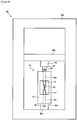
- FIG 1 is a front view showing a stress test jig according to one embodiment of the present invention.
- the stress test jig 10 according to this embodiment (hereinafter described as "jig 10") includes an upper cylinder 12, a lower cylinder 14, and a frame 16.
- the upper cylinder 12, the lower cylinder 14 and the frame 16 are respectively made of metal, for example.
- the upper cylinder 12 has a columnar shape or a cylindrical shape, for example.
- a through hole 12a is formed in an upper end portion of the upper cylinder 12, and the through hole 12a penetrates the upper cylinder 12 in a radial direction.
- a connecting pin 52 described later is to be inserted into the through hole 12a.
- a screw hole 12b is formed in a lower end portion of the upper cylinder 12. The screw hole 12b is formed so as to extend upward from a lower surface 12c of the upper cylinder 12 such that the screw hole 12b opens on the lower surface 12c of the upper cylinder 12.
- the lower cylinder 14 has a columnar shape or a cylindrical shape, for example.
- a through hole 14a is formed at a lower end portion of the lower cylinder 14, and the through hole 14a penetrates the lower cylinder 14 in a radial direction.
- a connecting pin 50 described later (see Figure 4 ) is to be inserted into the through hole 14a.
- a screw hole 14b is formed at an upper end portion of the lower cylinder 14. The screw hole 14b is formed so as to extend downward from an upper surface 14c of the lower cylinder 14 such that the screw hole 14b opens on the upper surface 14c of the lower cylinder 14.
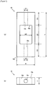
- Figure 2 is a view showing the frame 16, wherein Figure 2(a) is a front view, and Figure 2(b) is a bottom view.
- the frame 16 has a closed cross sectional shape.
- the frame 16 has an accommodating space 16a, an upper through hole 16b, a lower through hole 16c, and a flat surface 16d provided below the accommodating space 16a.
- the accommodating space 16a is formed so as to penetrate the frame 16 in a horizontal direction.
- the accommodating space 16a is a through hole which penetrates the frame 16 in the horizontal direction.
- the accommodating space 16a has a substantially rectangular shape as viewed in a front view, and is formed at the center portion of the frame 16. A test specimen 20 described later is accommodated in the accommodating space 16a.
- a length W1 of the accommodating space 16a in the vertical direction is set to 100 mm or more and 200 mm or less, for example. Setting the length W1 to 100 mm or more improves workability in mounting the test specimen 20 described later on the jig 10, and workability in attaching an extensometer 30 described later on the test specimen 20. Further, setting the length W1 to 200 mm or less more effectively suppresses buckling in the test specimen 20. As viewed in a front view, the width W2 of the accommodating space 16a in the horizontal direction is set to approximately 100 mm, for example.
- the upper through hole 16b and the lower through hole 16c are formed so as to penetrate the frame 16.
- the upper through hole 16b is formed so as to extend upward from the accommodating space 16a
- the lower through hole 16c is formed so as to extend downward from the accommodating space 16a.
- the upper through hole 16b and the lower through hole 16c are formed coaxially with each other.
- the upper through hole 16b and the lower through hole 16c respectively have a circular shape.
- the upper cylinder 12 is inserted into the upper through hole 16b
- the lower cylinder 14 is inserted into the lower through hole 16c.
- Each of a clearance between the upper through hole 16b and the upper cylinder 12 and a clearance between the lower through hole 16c and the lower cylinder 14 is set to 0.3 mm or less, for example, and is preferably set to 0.1 mm or less.
- the frame 16 has a rectangular shape as viewed in a front view.
- a length L of the frame 16 in the vertical direction is set to approximately 550 mm, for example.
- a width A of the frame 16 in the horizontal direction is set to approximately 130 mm, for example.
- a thickness T of the frame 16 is set to approximately 50 mm, for example.
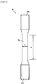
- Figure 3 is a view showing one example of a test specimen to be mounted on the jig 10.
- the test specimen 20 having a rod shape (round bar) is used.
- a screw groove is formed on each of an upper end portion 20a and a lower end portion 20b of the test specimen 20.
- the upper end portion 20a of the test specimen 20 is screwed into the screw hole 12b of the upper cylinder 12, and the lower end portion 20b of the test specimen 20 is screwed into the screw hole 14b of the lower cylinder 14.
- the upper cylinder 12 and the lower cylinder 14 are fixed to the test specimen 20.
- the upper cylinder 12 and the lower cylinder 14 fix the test specimen 20 such that the test specimen 20, the upper cylinder 12, and the lower cylinder 14 are positioned coaxially.
- the extensometer 30 is attached to the parallel portion 20c of the test specimen 20, and the extensometer 30 measures elongation of the parallel portion 20c in a stress test described later.
- a variety of known extensometers may be used as the extensometer 30, so that the detailed description of the extensometer 30 is omitted.
- Figure 4 is a view showing a stress testing machine used in performing the stress test method according to this embodiment.
- a variety of known testing machines may be used as the stress testing machine, so that the stress testing machine is described simply.
- the stress testing machine 40 used in the stress test method includes a body portion 40a, a crosshead 40b extending in the horizontal direction and supported on the body portion 40a in a movable manner in the vertical direction, and a support rod 40c provided below the crosshead 40b.
- the crosshead 40b is moved upward and downward by a driving device not shown in the drawing.
- the support rod 40c corresponds to a support portion which supports the flat surface 16d of the frame 16.
- the frame 16 of the jig 10, on which the test specimen 20 is mounted as described above is mounted on the stress testing machine 40.
- the jig 10 is installed such that the flat surface 16d of the frame 16 is supported on the upper surface of the support rod 40c.
- the frame 16 is supported on the support rod 40c of the stress testing machine 40 by the dead weight of the frame 16. In a state where the upper cylinder 12 and the lower cylinder 14 are not in contact with the frame 16, there is no possibility of a downward load being applied to the frame 16 from the stress testing machine 40 (crosshead 40b).
- the support rod 40c is formed so as to allow insertion of the lower end portion of the lower cylinder 14.
- the support rod 40c and the lower cylinder 14 are connected with each other by the connecting pin 50.
- the upper end portion of the upper cylinder 12 is inserted into a connecting rod 42, and is connected to the connecting rod 42 by the connecting pin 52.
- the connecting rod 42 is mounted on the crosshead 40b by way of a load cell 44. With such a configuration, the upper cylinder 12 and the crosshead 40b are connected with each other.
- the upper cylinder 12 which is moved upward and downward by the crosshead 40b, the test specimen 20 which is fixed to the upper cylinder 12, and the lower cylinder 14 which supports the test specimen 20 can be coaxially arranged. Further, even if the upper cylinder 12 and the lower cylinder 14 begin to tilt, during a stress test, in a direction that may cause buckling in the test specimen 20, the frame 16 prevents the upper cylinder 12 and the lower cylinder 14 from tilting significantly. To be more specific, the upper cylinder 12 and the lower cylinder 14 come into contact with the frame 16 in the upper through hole 16b and the lower through hole 16c, thus preventing the upper cylinder 12 and the lower cylinder 14 from tilting significantly.
- the upper cylinder 12 and the crosshead 40b can be connected to each other with a simple configuration which uses the connecting pin 52. Accordingly, compared to a configuration disclosed in Patent Document 1 where an upper flange and a crosshead are required to connect with each other using a plurality of screws, attaching of the jig 10 to and mounting of the test specimen 20 on the stress testing machine 40 can be facilitated.
- the extensometer 30 can be attached to the parallel portion 20c. Further, there is no possibility of the parallel portion 20c and the jig 10 coming into contact with each other. As a result, the relationship between stress and strain which are generated in the test specimen 20 can be investigated with high accuracy.
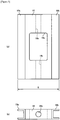
- gripping members 18a, 18b having a C shape as viewed in a plan view may be respectively provided to both side surfaces of the frame 16.
- a width E is set to approximately 200 mm, for example.
- a C-shaped steel section may be used for each of the gripping members 18a, 18b, for example.
- a compressive load and a tensile load were repeatedly applied to a test specimen 20 so as to investigate the relationship between stress and strain which are generated in the test specimen 20.
- a frame 16 provided with C-shaped steel sections 18a, 18b (see Figure 5 ) was used.
- each of a length C1 and a length C2 was set to 200 mm
- a length W1 was set to 150 mm
- a width W2 was set to 100 mm
- a width A was set to 130 mm
- a thickness T was set to 50 mm
- each of a diameter D1 and a diameter D2 was set to 32 mm
- a width E (see Figure 5 ) was set to 200 mm.
- each of a length of an upper end portion 20a and a length of a lower end portion 20b was set to 6.3 mm
- a length B of a parallel portion 20c was set to 8.0 mm
- a diameter d was set to 2.5 mm
- an overall length of the test specimen 20 was set to 25.5 mm.
- each of a clearance between an upper through hole 16b and an upper cylinder 12 and a clearance between a lower through hole 16c and a lower cylinder 14 was 0.1 mm.
- buckling in a test specimen can be suppressed without covering an area around a parallel portion. Accordingly, the relationship between stress and strain in metal products can be properly evaluated.
Landscapes
- Physics & Mathematics (AREA)
- Health & Medical Sciences (AREA)
- Life Sciences & Earth Sciences (AREA)
- Chemical & Material Sciences (AREA)
- Analytical Chemistry (AREA)
- Biochemistry (AREA)
- General Health & Medical Sciences (AREA)
- General Physics & Mathematics (AREA)
- Immunology (AREA)
- Pathology (AREA)
- Investigating Strength Of Materials By Application Of Mechanical Stress (AREA)
Abstract
Description
- The present invention relates to a stress test jig and a stress test method, and particularly relates to a jig and a test method which can be preferably used in a stress test for a rod-shaped test specimen.
- Oil country tubular goods (OCTG) are used in oil wells and gas wells (in this specification, oil wells and gas wells are collectively referred to as "oil wells"). The oil wells have a corrosive environment. Accordingly, oil country tubular goods are required to have corrosion resistance. Types of oil country tubular goods include a casing and a tubing. The casing is inserted into a well bore. A gap formed between the casing and the wall of the well bore is filled with cement so that the casing is fixed in the well bore. The tubing is inserted into the casing, and a production fluid, such as oil and gas, passes through the tubing. The oil country tubular goods are also required to have high strength together with corrosion resistance. In general, the strength grade of oil country tubular goods is defined by tensile yield strength in an axial direction of the oil country tubular goods. A user of oil country tubular goods performs trial drilling, geological surveys and the like so as to investigate the environment (formation pressure, the temperature of a production fluid, and pressure of the production fluid) of a well to be drilled, and selects oil country tubular goods with a sufficiently durable strength grade. Recently, wells have become deeper and hence, oil country tubular goods are required to have not only high tensile yield strength but also high compressive yield strength. Accordingly, tests are performed on oil country tubular goods in advance so as to understand deformation behavior of the oil country tubular goods when tensile stress or compressive stress is generated.
- As the test for understanding deformation behavior of steel products when compressive stress is generated, for example, a compression test which is defined by ASTM E9-09 may be used. In this compression test, an upper end face and a lower end face of a test specimen having a columnar shape is pressed by a flat compression jig. With such an operation, compressive stress can be generated in the test specimen.
- However, in a compression test of steel products, buckling in a test specimen causes a problem. For example, in the above-mentioned compression test defined by ASTM E9-09, if the flatness of a pressing surface of the compression jig which presses a test specimen is reduced, the pressing direction of the compression jig may tilt with respect to the axial direction of the test specimen. Such tilting may cause buckling in the test specimen.
- In view of the above, a jig for preventing the above-mentioned buckling is proposed. For example,
Patent Document 1 discloses a stress test jig which includes: a flange which holds an upper end portion of a test specimen (hereinafter referred to as "upper flange"); a flange which holds a lower end portion of the test specimen (hereinafter referred to as "lower flange"); an upper fixing member to which the upper flange is fixed; a lower fixing member to which the lower flange is fixed; and two guide members which penetrate the upper fixing member in the vertical direction. - In the stress test jig disclosed in
Patent Document 1, the upper flange moves upward and downward by moving the upper fixing member upward and downward. Such movement can generate compressive stress or tensile stress in the test specimen held by the upper flange. Further, in the stress test jig disclosed inPatent Document 1, the upper fixing member can be moved upward and downward along the guide members and hence, it is possible to prevent the upper fixing member from tilting when the upper fixing member moves upward and downward. Accordingly, it is possible to prevent the upper flange, which is fixed to the guide members, from tilting and hence, it is possible to prevent a loading direction of a compressive load and a tensile load on the test specimen from tilting with respect to the axial direction of the test specimen. As a result, occurrence of buckling can be suppressed. - Patent Document 2 discloses a jig for preventing buckling in a compression test specimen. In the jig disclosed in Patent Document 2, a parallel portion of the test specimen is surrounded by a plurality of members, thus preventing the generation of bends on the parallel portion.
-
- Patent Document 1:
JP2008-241530A - Patent Document 2:
JP61-102851U - However, when the jig disclosed in
Patent Document 1 is used, the upper flange which holds the upper end portion of the test specimen is required to be fixed to the upper fixing member by screws or the like. Accordingly, without sufficient improvement of assembly accuracy between the upper flange and the upper fixing member, even though the guide member suppresses tilting of the upper fixing member, the upper flange may tilt. Therefore, there may be a case where the loading direction of a compressive load and a tensile load on the test specimen tilts, so that occurrence of buckling cannot be sufficiently suppressed. - On the other hand, the jig disclosed in Patent Document 2 is configured so as to surround the parallel portion of the test specimen as described above. Accordingly, when the jig disclosed in Patent Document 2 is used, an extensometer for measuring elongation of the parallel portion cannot be attached to the parallel portion. In this case, the relationship between stress and strain which are generated in the test specimen cannot be investigated with high accuracy. That is, the relationship between stress and strain in metal products cannot be properly evaluated.
- Further, in the configuration disclosed in Patent Document 2, the parallel portion of the test specimen may contact to the jig. In this case, a force is applied to the parallel portion from the jig due to a contact of the parallel portion of the test specimen to the jig and hence, the relationship between stress and strain cannot be investigated with high accuracy.
- The present invention has been made to solve such problems, and it is an objective of the present invention to provide a stress test jig and a stress test method which can suppress buckling in test specimen without covering an area around the parallel portion.
- The gist of the present invention is the following stress test jig and stress test method.
- (1) A stress test jig which is used in a stress testing machine, the stress testing machine applying at least one of a compressive load and a tensile load to a rod-shaped test specimen which is disposed so as to extend in a vertical direction, the stress test jig including:
- an upper cylinder configured to allow an upper end portion of the test specimen to be fixed to a lower end portion of the upper cylinder;
- a lower cylinder configured to allow a lower end portion of the test specimen to be fixed to an upper end portion of the lower cylinder; and
- a frame configured to allow insertion of the upper cylinder and the lower cylinder, wherein
- the upper cylinder and the lower cylinder allow the test specimen to be fixed such that the test specimen, the upper cylinder, and the lower cylinder are positioned coaxially, and
- the frame includes: an accommodating space penetrating the frame in a horizontal direction, and capable of accommodating the test specimen; an upper through hole extending upward from the accommodating space so as to penetrate the frame, and allowing insertion of the upper cylinder; and a lower through hole extending downward from the accommodating space so as to penetrate the frame coaxially with the upper through hole, and allowing insertion of the lower cylinder.
- (2) The stress test jig according to the above-mentioned (1), wherein
the stress testing machine includes: a crosshead provided in a movable manner in a vertical direction; and a support portion provided below the crosshead,
the frame has a flat surface provided below the accommodating space, and supported by the support portion of the stress testing machine,
an upper end portion of the upper cylinder is formed so as to be connectable to the crosshead, and
a lower end portion of the lower cylinder is formed so as to be connectable to the support portion. - (3) The stress test jig according to the above-mentioned (1) or (2), wherein
the lower end portion of the upper cylinder is configured to allow the upper end portion of the test specimen to be fixed by screwing the upper end portion of the test specimen into the lower end portion of the upper cylinder, and
the upper end portion of the lower cylinder is configured to allow the lower end portion of the test specimen to be fixed by screwing the lower end portion of the test specimen into the upper end portion of the lower cylinder. - (4) A stress test method where at least one of a compressive load and a tensile load is applied to a rod-shaped test specimen using a stress testing machine, the stress testing machine including a crosshead provided in a movable manner in a vertical direction and a support portion provided below the crosshead, the stress test method including:
- mounting the test specimen on the stress test jig described in any one of the above-mentioned (1) to (3) which is disposed on the support portion, and connecting the crosshead to the upper cylinder of the stress test jig; and
- applying at least one of the compressive load and the tensile load to the test specimen by moving the crosshead in the vertical direction.
- According to the present invention, buckling in a test specimen can be suppressed without covering an area around the parallel portion. Accordingly, the relationship between stress and strain in metal products can be properly evaluated.
-
-
Figure 1 is a front view showing a stress test jig according to one embodiment of the present invention. -
Figure 2 is a view showing a frame, whereinFigure 2(a) is a front view, andFigure 2(b) is a bottom view. -
Figure 3 is a view showing one example of a test specimen. -
Figure 4 is a view showing a stress testing machine to which a jig is attached. -
Figure 5 is a view showing a frame to which gripping members are attached, whereinFigure 5(a) is a front view, andFigure 5(b) is a bottom view. -
Figure 6 is a view showing an investigation result (relationship between stress and strain) in an example. - Hereinafter, a stress test jig and a stress test method which uses the stress test jig according to one embodiment of the present invention are described in detail. As described later, the stress test jig according to this embodiment is used in a stress testing machine which can apply at least one of a compressive load and a tensile load to a rod-shaped test specimen which is disposed so as to extend in the vertical direction.
-
Figure 1 is a front view showing a stress test jig according to one embodiment of the present invention. Referring toFigure 1 , thestress test jig 10 according to this embodiment (hereinafter described as "jig 10") includes anupper cylinder 12, alower cylinder 14, and aframe 16. Theupper cylinder 12, thelower cylinder 14 and theframe 16 are respectively made of metal, for example. - The
upper cylinder 12 has a columnar shape or a cylindrical shape, for example. A throughhole 12a is formed in an upper end portion of theupper cylinder 12, and the throughhole 12a penetrates theupper cylinder 12 in a radial direction. A connectingpin 52 described later (seeFigure 4 ) is to be inserted into the throughhole 12a. Ascrew hole 12b is formed in a lower end portion of theupper cylinder 12. Thescrew hole 12b is formed so as to extend upward from alower surface 12c of theupper cylinder 12 such that thescrew hole 12b opens on thelower surface 12c of theupper cylinder 12. - The
lower cylinder 14 has a columnar shape or a cylindrical shape, for example. A throughhole 14a is formed at a lower end portion of thelower cylinder 14, and the throughhole 14a penetrates thelower cylinder 14 in a radial direction. A connectingpin 50 described later (seeFigure 4 ) is to be inserted into the throughhole 14a. Ascrew hole 14b is formed at an upper end portion of thelower cylinder 14. Thescrew hole 14b is formed so as to extend downward from anupper surface 14c of thelower cylinder 14 such that thescrew hole 14b opens on theupper surface 14c of thelower cylinder 14. -
Figure 2 is a view showing theframe 16, whereinFigure 2(a) is a front view, andFigure 2(b) is a bottom view. Referring toFigure 1 andFigure 2 , theframe 16 has a closed cross sectional shape. In this embodiment, theframe 16 has anaccommodating space 16a, an upper throughhole 16b, a lower throughhole 16c, and aflat surface 16d provided below theaccommodating space 16a. - The
accommodating space 16a is formed so as to penetrate theframe 16 in a horizontal direction. In other words, theaccommodating space 16a is a through hole which penetrates theframe 16 in the horizontal direction. In this embodiment, theaccommodating space 16a has a substantially rectangular shape as viewed in a front view, and is formed at the center portion of theframe 16. Atest specimen 20 described later is accommodated in theaccommodating space 16a. - A length W1 of the
accommodating space 16a in the vertical direction is set to 100 mm or more and 200 mm or less, for example. Setting the length W1 to 100 mm or more improves workability in mounting thetest specimen 20 described later on thejig 10, and workability in attaching anextensometer 30 described later on thetest specimen 20. Further, setting the length W1 to 200 mm or less more effectively suppresses buckling in thetest specimen 20. As viewed in a front view, the width W2 of theaccommodating space 16a in the horizontal direction is set to approximately 100 mm, for example. - Referring to
Figure 1 andFigure 2 , the upper throughhole 16b and the lower throughhole 16c are formed so as to penetrate theframe 16. To be more specific, the upper throughhole 16b is formed so as to extend upward from theaccommodating space 16a, and the lower throughhole 16c is formed so as to extend downward from theaccommodating space 16a. The upper throughhole 16b and the lower throughhole 16c are formed coaxially with each other. - On cross sections of the
frame 16 which extend in the horizontal direction (that is, cross sections perpendicular to the vertical direction), the upper throughhole 16b and the lower throughhole 16c respectively have a circular shape. Referring toFigure 1 , theupper cylinder 12 is inserted into the upper throughhole 16b, and thelower cylinder 14 is inserted into the lower throughhole 16c. Each of a clearance between the upper throughhole 16b and theupper cylinder 12 and a clearance between the lower throughhole 16c and thelower cylinder 14 is set to 0.3 mm or less, for example, and is preferably set to 0.1 mm or less. - Referring to
Figure 2 , it is preferable to set a length C1 of the upper throughhole 16b in the vertical direction and a diameter D1 of the upper throughhole 16b so as to satisfy the following formula (1). It is preferable to set a length C2 of the lower throughhole 16c in the vertical direction and a diameter D2 of the lower throughhole 16c so as to satisfy the following formula (2). It is more preferable to set the length C1 and the diameter D1 so as to satisfy the following formula (3). It is more preferable to set the length C2 and the diameter D2 so as to satisfy the following formula (4).



- In this embodiment, the
frame 16 has a rectangular shape as viewed in a front view. A length L of theframe 16 in the vertical direction is set to approximately 550 mm, for example. A width A of theframe 16 in the horizontal direction is set to approximately 130 mm, for example. A thickness T of theframe 16 is set to approximately 50 mm, for example. -
Figure 3 is a view showing one example of a test specimen to be mounted on thejig 10. As shown inFigure 3 , in this embodiment, thetest specimen 20 having a rod shape (round bar) is used. A screw groove is formed on each of anupper end portion 20a and alower end portion 20b of thetest specimen 20. From the viewpoint of suppressing buckling in thetest specimen 20, it is preferable to set a length B of aparallel portion 20c and a diameter d of theparallel portion 20c so as to satisfy the following formula (5), for example.
- Referring to
Figure 1 andFigure 3 , in this embodiment, theupper end portion 20a of thetest specimen 20 is screwed into thescrew hole 12b of theupper cylinder 12, and thelower end portion 20b of thetest specimen 20 is screwed into thescrew hole 14b of thelower cylinder 14. With such a configuration, theupper cylinder 12 and thelower cylinder 14 are fixed to thetest specimen 20. In this embodiment, theupper cylinder 12 and thelower cylinder 14 fix thetest specimen 20 such that thetest specimen 20, theupper cylinder 12, and thelower cylinder 14 are positioned coaxially. Theextensometer 30 is attached to theparallel portion 20c of thetest specimen 20, and theextensometer 30 measures elongation of theparallel portion 20c in a stress test described later. A variety of known extensometers may be used as theextensometer 30, so that the detailed description of theextensometer 30 is omitted. - Next, a stress test method using the above-mentioned
jig 10 is described.Figure 4 is a view showing a stress testing machine used in performing the stress test method according to this embodiment. A variety of known testing machines may be used as the stress testing machine, so that the stress testing machine is described simply. - Referring to
Figure 4 , thestress testing machine 40 used in the stress test method according to this embodiment includes abody portion 40a, acrosshead 40b extending in the horizontal direction and supported on thebody portion 40a in a movable manner in the vertical direction, and asupport rod 40c provided below thecrosshead 40b. Thecrosshead 40b is moved upward and downward by a driving device not shown in the drawing. In this embodiment, thesupport rod 40c corresponds to a support portion which supports theflat surface 16d of theframe 16. - In performing the stress test, for example, the
frame 16 of thejig 10, on which thetest specimen 20 is mounted as described above, is mounted on thestress testing machine 40. To be more specific, thejig 10 is installed such that theflat surface 16d of theframe 16 is supported on the upper surface of thesupport rod 40c. In this embodiment, theframe 16 is supported on thesupport rod 40c of thestress testing machine 40 by the dead weight of theframe 16. In a state where theupper cylinder 12 and thelower cylinder 14 are not in contact with theframe 16, there is no possibility of a downward load being applied to theframe 16 from the stress testing machine 40 (crosshead 40b). - Although the detailed description is omitted, the
support rod 40c is formed so as to allow insertion of the lower end portion of thelower cylinder 14. In this embodiment, thesupport rod 40c and thelower cylinder 14 are connected with each other by the connectingpin 50. - The upper end portion of the
upper cylinder 12 is inserted into a connectingrod 42, and is connected to the connectingrod 42 by the connectingpin 52. The connectingrod 42 is mounted on thecrosshead 40b by way of aload cell 44. With such a configuration, theupper cylinder 12 and thecrosshead 40b are connected with each other. - By moving the
crosshead 40b upward and downward in a state where thetest specimen 20 is mounted on thejig 10, and thecrosshead 40b is connected to theupper cylinder 12 as described above, a compressive load and a tensile load can be applied to thetest specimen 20. - As described above, when the
jig 10 according to this embodiment is used, theupper cylinder 12 which is moved upward and downward by thecrosshead 40b, thetest specimen 20 which is fixed to theupper cylinder 12, and thelower cylinder 14 which supports thetest specimen 20 can be coaxially arranged. Further, even if theupper cylinder 12 and thelower cylinder 14 begin to tilt, during a stress test, in a direction that may cause buckling in thetest specimen 20, theframe 16 prevents theupper cylinder 12 and thelower cylinder 14 from tilting significantly. To be more specific, theupper cylinder 12 and thelower cylinder 14 come into contact with theframe 16 in the upper throughhole 16b and the lower throughhole 16c, thus preventing theupper cylinder 12 and thelower cylinder 14 from tilting significantly. Accordingly, in this embodiment, even without sufficiently improving assembly accuracy between theupper cylinder 12 and thecrosshead 40b, it is possible to prevent theupper cylinder 12 and thelower cylinder 14 from tilting with respect to the vertical direction. As a result, it is possible to prevent a loading direction of a compressive load and a tensile load on thetest specimen 20 from tilting with respect to the vertical direction and hence, occurrence of buckling in thetest specimen 20 can be sufficiently suppressed. - Further, as described above, it is unnecessary to improve assembly accuracy between the
upper cylinder 12 and thecrosshead 40b more than necessary and hence, a connection structure between theupper cylinder 12 and thecrosshead 40b can be simplified. In this embodiment, as described above, theupper cylinder 12 and thecrosshead 40b can be connected to each other with a simple configuration which uses the connectingpin 52. Accordingly, compared to a configuration disclosed inPatent Document 1 where an upper flange and a crosshead are required to connect with each other using a plurality of screws, attaching of thejig 10 to and mounting of thetest specimen 20 on thestress testing machine 40 can be facilitated. - In this embodiment, it is unnecessary to cover an area around the
parallel portion 20c of thetest specimen 20 by thejig 10 and hence, theextensometer 30 can be attached to theparallel portion 20c. Further, there is no possibility of theparallel portion 20c and thejig 10 coming into contact with each other. As a result, the relationship between stress and strain which are generated in thetest specimen 20 can be investigated with high accuracy. - Although the detailed description is omitted, for example, as shown in
Figure 5 , to facilitate carrying of theframe 16, grippingmembers frame 16. In this case, a width E is set to approximately 200 mm, for example. A C-shaped steel section may be used for each of thegripping members - To check advantageous effects of the present invention, using a
jig 10 and astress testing machine 40 having the above-mentioned configuration, a compressive load and a tensile load were repeatedly applied to atest specimen 20 so as to investigate the relationship between stress and strain which are generated in thetest specimen 20. - In this example, a
frame 16 provided with C-shapedsteel sections Figure 5 ) was used. Referring toFigure 2 , each of a length C1 and a length C2 was set to 200 mm, a length W1 was set to 150 mm, a width W2 was set to 100 mm, a width A was set to 130 mm, a thickness T was set to 50 mm, each of a diameter D1 and a diameter D2 was set to 32 mm, and a width E (seeFigure 5 ) was set to 200 mm. Further, referring toFigure 3 , in the axial direction of thetest specimen 20, each of a length of anupper end portion 20a and a length of alower end portion 20b was set to 6.3 mm, a length B of aparallel portion 20c was set to 8.0 mm, a diameter d was set to 2.5 mm, and an overall length of thetest specimen 20 was set to 25.5 mm. Referring toFigure 1 , each of a clearance between an upper throughhole 16b and anupper cylinder 12 and a clearance between a lower throughhole 16c and alower cylinder 14 was 0.1 mm. - The relationship between stress and strain (hysteresis curve) obtained by the investigation is shown in
Figure 6 . In this example, buckling in thetest specimen 20 did not occur during the test. That is, according to the present invention, it is understood that the relationship between stress and strain can be properly evaluated while occurrence of buckling is prevented. - According to the present invention, buckling in a test specimen can be suppressed without covering an area around a parallel portion. Accordingly, the relationship between stress and strain in metal products can be properly evaluated.
-
- 10 stress test jig
- 12 upper cylinder
- 14 lower cylinder
- 16 frame
- 16a accommodating space
- 16b upper through hole
- 16c lower through hole
- 16d flat surface
- 20 test specimen
- 30 extensometer
- 40 stress testing machine
Claims (4)
- A stress test jig which is used in a stress testing machine, the stress testing machine applying at least one of a compressive load and a tensile load to a rod-shaped test specimen which is disposed so as to extend in a vertical direction, the stress test jig comprising:an upper cylinder configured to allow an upper end portion of the test specimen to be fixed to a lower end portion of the upper cylinder;a lower cylinder configured to allow a lower end portion of the test specimen to be fixed to an upper end portion of the lower cylinder; anda frame configured to allow insertion of the upper cylinder and the lower cylinder, whereinthe upper cylinder and the lower cylinder allow the test specimen to be fixed such that the test specimen, the upper cylinder, and the lower cylinder are positioned coaxially, andthe frame includes: an accommodating space penetrating the frame in a horizontal direction, and capable of accommodating the test specimen; an upper through hole extending upward from the accommodating space so as to penetrate the frame, and allowing insertion of the upper cylinder; and a lower through hole extending downward from the accommodating space so as to penetrate the frame coaxially with the upper through hole, and allowing insertion of the lower cylinder.
- The stress test jig according to claim 1, wherein
the stress testing machine includes: a crosshead provided in a movable manner in a vertical direction; and a support portion provided below the crosshead,
the frame has a flat surface provided below the accommodating space, and supported by the support portion of the stress testing machine,
an upper end portion of the upper cylinder is formed so as to be connectable to the crosshead, and
a lower end portion of the lower cylinder is formed so as to be connectable to the support portion. - The stress test jig according to claim 1 or 2, wherein
the lower end portion of the upper cylinder is configured to allow the upper end portion of the test specimen to be fixed by screwing the upper end portion of the test specimen into the lower end portion of the upper cylinder, and
the upper end portion of the lower cylinder is configured to allow the lower end portion of the test specimen to be fixed by screwing the lower end portion of the test specimen into the upper end portion of the lower cylinder. - A stress test method where at least one of a compressive load and a tensile load is applied to a rod-shaped test specimen using a stress testing machine, the stress testing machine including a crosshead provided in a movable manner in a vertical direction and a support portion provided below the crosshead, the stress test method comprising:mounting the test specimen on the stress test jig described in any one of claims 1 to 3 which is disposed on the support portion, and connecting the crosshead to the upper cylinder of the stress test jig; andapplying at least one of the compressive load and the tensile load to the test specimen by moving the crosshead in the vertical direction.
Applications Claiming Priority (2)
| Application Number | Priority Date | Filing Date | Title |
|---|---|---|---|
| JP2016213291 | 2016-10-31 | ||
| PCT/JP2017/025994 WO2018078965A1 (en) | 2016-10-31 | 2017-07-18 | Stress test jig and stress test method |
Publications (2)
| Publication Number | Publication Date |
|---|---|
| EP3534141A1 true EP3534141A1 (en) | 2019-09-04 |
| EP3534141A4 EP3534141A4 (en) | 2020-06-24 |
Family
ID=62023334
Family Applications (1)
| Application Number | Title | Priority Date | Filing Date |
|---|---|---|---|
| EP17865347.3A Withdrawn EP3534141A4 (en) | 2016-10-31 | 2017-07-18 | CONSTRAINT TEST TEMPLATE AND RELATED METHOD |
Country Status (6)
| Country | Link |
|---|---|
| US (1) | US11002647B2 (en) |
| EP (1) | EP3534141A4 (en) |
| JP (1) | JP6801720B2 (en) |
| KR (1) | KR20190070966A (en) |
| CN (1) | CN109952500B (en) |
| WO (1) | WO2018078965A1 (en) |
Families Citing this family (12)
| Publication number | Priority date | Publication date | Assignee | Title |
|---|---|---|---|---|
| US10746640B2 (en) * | 2017-03-21 | 2020-08-18 | Textron Innovations Inc. | Methods of making a tubular specimen with a predetermined wrinkle defect |
| US10744727B2 (en) | 2017-03-21 | 2020-08-18 | Textron Innovations Inc. | Methods of making a specimen with a predetermined wrinkle defect |
| CN109030196B (en) * | 2018-08-18 | 2021-10-29 | 深圳阿尔泰克轻合金技术有限公司 | Metal material uniaxial creep resistance test sample, clamp and method |
| CN110631902B (en) * | 2019-10-31 | 2024-05-28 | 浙江工业大学 | Clamp convenient to safely and quickly install CT (computed tomography) sample |
| KR102347759B1 (en) * | 2020-07-14 | 2022-01-06 | 주식회사 선일다이파스 | Tensile test device and method of aluminum pipe |
| CN112414841B (en) * | 2020-10-13 | 2023-11-24 | 重庆工商大学 | Device and method for testing circumferential tensile strength of self-adaptive pilot pipe |
| US12241873B2 (en) * | 2021-05-07 | 2025-03-04 | Mitchell Z. Dziekonski | Dynamic autoclave testing system |
| CN113804538A (en) * | 2021-08-05 | 2021-12-17 | 北京航空航天大学 | An anti-instability fixture for pre-cracked CT specimens under compressive-compression cyclic loading |
| KR102385479B1 (en) * | 2021-10-19 | 2022-04-12 | 건설공인시험연구원 주식회사 | Strength testing device |
| CN114112681B (en) * | 2021-12-16 | 2024-08-20 | 合肥工业大学 | Compression experiment comprehensive device and experiment method |
| CN114941996B (en) * | 2022-07-26 | 2022-11-01 | 西北工业大学 | Fiber grating strain measurement system for round bar fatigue sample |
| US12441487B1 (en) * | 2023-04-11 | 2025-10-14 | United Launch Alliance, L.L.C. | Hydraulic over elastic separation mechanism |
Family Cites Families (26)
| Publication number | Priority date | Publication date | Assignee | Title |
|---|---|---|---|---|
| US3741005A (en) * | 1971-09-28 | 1973-06-26 | Int Paper Co | Wet web tensile tester |
| JPS52119379A (en) * | 1976-03-31 | 1977-10-06 | Sumitomo Metal Ind | Construction of sample grip section of low cycle fatigue tester by tension and compression |
| JPS59194044A (en) | 1983-04-18 | 1984-11-02 | Nippon Denso Co Ltd | Fuel injection quantity controller for diesel engine |
| JPS59194044U (en) * | 1983-06-09 | 1984-12-24 | 三菱重工業株式会社 | compression test jig |
| JPH0685536B2 (en) | 1984-10-25 | 1994-10-26 | 株式会社日立製作所 | Sub signal transmission method |
| JPS61102851U (en) * | 1984-12-10 | 1986-06-30 | ||
| US4843888A (en) * | 1987-07-23 | 1989-07-04 | Mts Systems Corporation | Self aligning test grip |
| DE3912075A1 (en) * | 1989-04-10 | 1990-10-11 | Bam Bundesanstalt Matforschung | DEVICE AND METHOD FOR THE ONE-AXLE MECHANICAL MATERIAL TESTING |
| JP2506774Y2 (en) * | 1990-06-29 | 1996-08-14 | 株式会社島津製作所 | Material testing machine |
| JPH0754288B2 (en) | 1991-03-29 | 1995-06-07 | 株式会社島津製作所 | Material testing machine with telescopic screw rod |
| US5313841A (en) * | 1992-07-09 | 1994-05-24 | Quantum Materials, Inc. | Die adhesion testing method and apparatus |
| US5279166A (en) * | 1992-09-29 | 1994-01-18 | Eg&G Idaho, Inc. | Self-aligning biaxial load frame |
| JP2001235409A (en) * | 2000-02-25 | 2001-08-31 | Shimadzu Corp | Fine wire sample test jig |
| AU2001265372B2 (en) * | 2000-06-06 | 2005-07-07 | Mts Systems Corporation | Statistically rigid and dynamically compliant material testing system |
| JP2003106964A (en) * | 2001-10-01 | 2003-04-09 | Ishikawajima Harima Heavy Ind Co Ltd | Specimen fixing adapter for tensile material testing machine |
| US7441468B2 (en) * | 2005-11-17 | 2008-10-28 | C.B. Fleet Company, Incorporated | Squeeze force measuring system |
| JP2008241530A (en) | 2007-03-28 | 2008-10-09 | Sumitomo Metal Ind Ltd | Stress test jig and stress test method |
| CA2635551C (en) * | 2008-06-23 | 2013-04-09 | Schlumberger Canada Limited | Environmental mechanical test apparatus |
| JP5229179B2 (en) * | 2009-10-09 | 2013-07-03 | 株式会社島津製作所 | Material testing machine |
| WO2012011173A1 (en) * | 2010-07-22 | 2012-01-26 | 株式会社島津製作所 | Material testing machine |
| JP6004113B2 (en) * | 2013-08-07 | 2016-10-05 | 株式会社島津製作所 | Jig mounting device for material testing machine |
| JP6032162B2 (en) * | 2013-09-09 | 2016-11-24 | 株式会社島津製作所 | Displacement meter |
| KR200477566Y1 (en) * | 2014-03-20 | 2015-06-24 | 삼성중공업 주식회사 | Jig for tensile test |
| US9291537B2 (en) | 2014-05-14 | 2016-03-22 | Ut-Battelle, Llc | Liquid salt environment stress-rupture testing |
| JP6143714B2 (en) * | 2014-06-18 | 2017-06-07 | エスペック株式会社 | Test device and thermostatic device |
| CN204831910U (en) * | 2015-08-17 | 2015-12-02 | 西安热工研究院有限公司 | Bolt sample anchor clamps of reheat crack(ing) sensitivity test |
-
2017
- 2017-07-18 CN CN201780067730.5A patent/CN109952500B/en active Active
- 2017-07-18 JP JP2018547120A patent/JP6801720B2/en active Active
- 2017-07-18 WO PCT/JP2017/025994 patent/WO2018078965A1/en not_active Ceased
- 2017-07-18 EP EP17865347.3A patent/EP3534141A4/en not_active Withdrawn
- 2017-07-18 US US16/345,050 patent/US11002647B2/en active Active
- 2017-07-18 KR KR1020197014724A patent/KR20190070966A/en not_active Ceased
Also Published As
| Publication number | Publication date |
|---|---|
| EP3534141A4 (en) | 2020-06-24 |
| JPWO2018078965A1 (en) | 2019-06-24 |
| JP6801720B2 (en) | 2020-12-16 |
| CN109952500A (en) | 2019-06-28 |
| US20190242799A1 (en) | 2019-08-08 |
| WO2018078965A1 (en) | 2018-05-03 |
| CN109952500B (en) | 2021-08-24 |
| US11002647B2 (en) | 2021-05-11 |
| KR20190070966A (en) | 2019-06-21 |
Similar Documents
| Publication | Publication Date | Title |
|---|---|---|
| EP3534141A1 (en) | Stress test jig and stress test method | |
| Craveiro et al. | Buckling resistance of axially loaded cold-formed steel columns | |
| CN201322704Y (en) | Composite loading clamping device | |
| EP2833112A1 (en) | Large deformation tensile testing system | |
| JP2008241530A (en) | Stress test jig and stress test method | |
| CN102539253B (en) | Tester for measuring real stress-strain curve of plate material under unidirectional compression state | |
| KR101313181B1 (en) | Specimen multiaxial loading test device | |
| Chen et al. | Experimental behaviour of stainless steel plate girders under combined bending and shear | |
| KR102171668B1 (en) | Apparatus and method for aligning with a test specimen | |
| EP3453904B1 (en) | Bearing structural member, support, joint assembly and tube section assembly | |
| Binwen et al. | Study on impact fatigue test and life prediction method of TC18 titanium alloy | |
| Hetz et al. | Characterization of sheet metal components by using an upsetting test with miniaturized cylindrical specimen | |
| Sarzosa et al. | Experimental and numerical study on the ductile fracture response of X65 girth-welded joint made of Inconel 625 alloy | |
| JP2013124999A (en) | Hydrogen embrittlement resistance characteristic evaluation method for thin steel sheet | |
| KR20120074353A (en) | Three point bending test machine | |
| KR101371759B1 (en) | Apparatus for testing specimen | |
| JP2007155665A (en) | Pre-crack introduction device, pre-crack introduction jig, and pre-crack introduction method | |
| KR100970205B1 (en) | Connecting pin load tester | |
| KR20130105318A (en) | Lug test apparatus | |
| CN217403661U (en) | Connector and counter-pulling device for detecting effective prestress under steel strand anchor after grouting | |
| KR20240133804A (en) | Test apparatus for biaxial flexure tensile strength of concrete | |
| RU2330261C1 (en) | Tensile testing clamp | |
| Furukawa et al. | Experimental analysis of the mechanical behavior of steel storage rack base plate upright connections | |
| Kasai et al. | Cyclic behavior and low-cycle fatigue of semi-rigid connections (Part I: Bolted angle connections) | |
| KR200437268Y1 (en) | Tensile Strength Tester of Rock Core Specimen |
Legal Events
| Date | Code | Title | Description |
|---|---|---|---|
| STAA | Information on the status of an ep patent application or granted ep patent |
Free format text: STATUS: THE INTERNATIONAL PUBLICATION HAS BEEN MADE |
|
| PUAI | Public reference made under article 153(3) epc to a published international application that has entered the european phase |
Free format text: ORIGINAL CODE: 0009012 |
|
| STAA | Information on the status of an ep patent application or granted ep patent |
Free format text: STATUS: REQUEST FOR EXAMINATION WAS MADE |
|
| 17P | Request for examination filed |
Effective date: 20190521 |
|
| AK | Designated contracting states |
Kind code of ref document: A1 Designated state(s): AL AT BE BG CH CY CZ DE DK EE ES FI FR GB GR HR HU IE IS IT LI LT LU LV MC MK MT NL NO PL PT RO RS SE SI SK SM TR |
|
| AX | Request for extension of the european patent |
Extension state: BA ME |
|
| DAV | Request for validation of the european patent (deleted) | ||
| DAX | Request for extension of the european patent (deleted) | ||
| A4 | Supplementary search report drawn up and despatched |
Effective date: 20200528 |
|
| RIC1 | Information provided on ipc code assigned before grant |
Ipc: G01N 3/08 20060101AFI20200520BHEP Ipc: G01N 3/04 20060101ALI20200520BHEP |
|
| STAA | Information on the status of an ep patent application or granted ep patent |
Free format text: STATUS: EXAMINATION IS IN PROGRESS |
|
| 17Q | First examination report despatched |
Effective date: 20220603 |
|
| STAA | Information on the status of an ep patent application or granted ep patent |
Free format text: STATUS: THE APPLICATION HAS BEEN WITHDRAWN |
|
| 18W | Application withdrawn |
Effective date: 20220930 |