EP3533947A1 - A supporting frame for an insulating frame for a roof window and a method of assembling a supporting frame - Google Patents
A supporting frame for an insulating frame for a roof window and a method of assembling a supporting frame Download PDFInfo
- Publication number
- EP3533947A1 EP3533947A1 EP18248013.7A EP18248013A EP3533947A1 EP 3533947 A1 EP3533947 A1 EP 3533947A1 EP 18248013 A EP18248013 A EP 18248013A EP 3533947 A1 EP3533947 A1 EP 3533947A1
- Authority
- EP
- European Patent Office
- Prior art keywords
- supporting
- connector
- rail
- bracket
- frame
- Prior art date
- Legal status (The legal status is an assumption and is not a legal conclusion. Google has not performed a legal analysis and makes no representation as to the accuracy of the status listed.)
- Granted
Links
Images





Classifications
-
- E—FIXED CONSTRUCTIONS
- E04—BUILDING
- E04D—ROOF COVERINGS; SKY-LIGHTS; GUTTERS; ROOF-WORKING TOOLS
- E04D13/00—Special arrangements or devices in connection with roof coverings; Protection against birds; Roof drainage ; Sky-lights
- E04D13/03—Sky-lights; Domes; Ventilating sky-lights
- E04D13/0305—Supports or connecting means for sky-lights of flat or domed shape
- E04D13/031—Supports or connecting means for sky-lights of flat or domed shape characterised by a frame for connection to an inclined roof
Definitions
- the present invention relates to a supporting frame for an insulating frame for a roof window, said supporting frame comprising top, bottom and side supporting rails, where one or more supporting rails are configured to carry insulating elements, each supporting rail comprising one or more rail connecting sections, and where said supporting frame further comprises a plurality of connector brackets, each of said connector brackets comprising two bracket connecting sections each connected to a rail connecting section of a supporting rail.
- the invention further relates to a method of assembling a supporting frame for an insulating frame for a roof window.
- An insulating frame for insulating the interface between a roof window and an inclined roof structure, in which the window is installed is known from EP2677092A1 .
- This insulating frame includes supporting rails extending along insulating elements and connector brackets used for interconnecting the supporting rails, thereby forming the insulating frame. It has proven to provide advantages over the previously known insulating frames as this frame can be assembled in-situ and is thus easier to handle for the installer. However, the stability of the insulating frame has been found to be insufficient in some installation situations, and it is further desired to reduce the production cost of the insulating frame.
- each of said connector brackets detachably interconnects two supporting rails so that the respective supporting rails are perpendicular to each other or interconnects two supporting rails in longitudinal continuation of each other, and where each of the connector brackets is double-walled with a hollow cross-section at the connecting sections, the hollow cross-section accommodating the rail connecting section, and where the connector bracket is made from a polymer.
- the rigidity of the connector bracket is increased without increasing the thermal conductivity of the insulating frame.
- the connector bracket being double-walled and hollow the connector bracket is allowed to act as a female connector, which may result in material savings as the supporting rails can be made with a simple single-walled cross-sectional shape. This may reduce the complexity of the production process of the supporting rails, thus potentially increasing efficiency and lowering production costs of the insulating frame.
- double-walled is intended to mean that at least the parts of the connector bracket serving as connecting sections must comprise walls forming a space between them, which is suitable for accommodating a connecting section of a supporting rail.
- the space does not have to be closed and parts of the cross-section can be single-walled, for example to allow the use with different types of supporting rails or to allow access to an engagement mechanism adapted for securing the connection between the connector bracket and the supporting rail.
- each other should be understood as the supporting rails being interconnected in their length direction such that their respective longitudinal axes are substantially collinear. This may allow the connector bracket to function as an extension piece in the supporting frame and so allow the dimensions of the supporting frame to be altered to a desired magnitude by interconnecting one or more supporting rails in longitudinal or lengthwise continuation of each other.
- the supporting rails may be made from a polymer in order to decrease costs and reduce thermal conductivity.
- bracket connecting sections comprise a projection, recess and/or opening adapted for snap locking with a corresponding projection, recess and/or opening on a rail connecting section. This may allow or facilitate snap locking between the supporting rails and the connector brackets, which may improve the ease of assembly of the supporting frame.
- the rail connecting sections or bracket connecting sections comprise a barb which is in engagement with a corresponding opening in the counterpart connecting section with which it is interconnected.
- the connection between the barb and the opening may be releasable for example by making the barb or a tab on which it is provided from an elastic material. This may facilitate the interconnected rail connecting sections and bracket connecting sections to be detached from each other in a non-destructive manner i.e. a detachable interconnection.
- a second aspect of the invention concerns an insulating frame for a roof window comprising the supporting frame according to the first aspect of the invention, where each supporting rail of said supporting frame carries an insulating element. It is, however, also possible to leave one or more supporting rails or part(s) thereof without insulation.
- a third aspect of the invention concerns a connector bracket configured for use in a supporting frame according the first aspect of the invention.
- the connector bracket has an angular cross-sectional shape, preferably an L-shape, at each connecting section, which may provide strength and stiffness as will be described below.
- the connector bracket comprises a flange portion adapted for securing the insulating frame to a roof structure. This may help keep the supporting frame in position as will be described below.
- the connector bracket configured for use in a supporting frame according the first aspect of the invention, further comprising an attachment device adapted for securing a rod, cord, string, or the like. This may help to maintain the intended shape of the supporting frame during installation and/or to confirm correct assembly of the frame as will be described below.
- a fourth aspect of the invention concerns a kit for making a supporting frame for an insulating frame for a roof window according to the first aspect of the invention, including a plurality of top, bottom and side supporting rails and a plurality of connector brackets.
- a fifth aspect of the invention concerns a method of assembling a supporting frame, comprising the steps of:
- an insulating frame for a roof window may be assembled if so desired.
- the method further comprises securing a flange portion of at least one connector bracket to a roof structure.
- a connector bracket which contributes to improving the stability of a supporting frame and which preferably also makes it cheaper to produce is achieved with a connector bracket, which is double-walled with a hollow cross-section at the connecting sections, the hollow cross-section being adapted to accommodate a supporting rail, and where the connector bracket is made from a polymer.
- the rigidity of the connector bracket is increased without increasing the thermal conductivity of the insulating frame.
- the connector bracket being double-walled and hollow the connector bracket is allowed to act as a female connector, which may result in material savings as the supporting rails can be made with a simple single-walled cross-sectional shape. This may reduce the complexity of the production process of the supporting rails, thus potentially increasing efficiency and lowering production costs of the insulating frame.
- said connector bracket is made as an angular bracket having two legs, which are substantially perpendicular to each other and each comprising a connecting section. This makes the connector bracket suitable for use at corners of the insulating frame so that the supporting rails can be relatively simple with a substantially continuous cross-sectional shape over their entire length.
- the connector bracket may also be used for interconnecting insulating elements arranged in continuation of each other, for example serving as an extension piece.
- the connector bracket has an angular cross-sectional shape, preferably an L-shape, at each connecting section.
- This allows the connector bracket to be connected to supporting rails having an angular cross-sectional shape perpendicular to their length direction.
- supporting rails are presently considered advantageous as they have good bending resistance.
- the supporting rails may be made from any suitable material selected from the group consisting of: steel, stainless steel, aluminium, other metals, polymers, ceramics, glass fibre, composites and combinations thereof.
- the connector bracket may comprise a plurality of recesses and/or openings. Such recesses or openings may also serve other purposes, such as allowing other items to pass through the connector bracket or be attached to it, or further reducing the thermal conductivity of the connector bracket, or facilitating automated handling of the connector bracket.
- the connector bracket should be made from a material of a dimensionally stable nature having good thermal insulating properties and rigidity, such as polyethylene, polypropylene, polyurethane, polyvinylchloride, polycaprolactam or acrylonitrile butadiene styrene.
- the connecting sections may comprise a projection, recess and/or opening adapted for snap locking with a corresponding projection, recess and/or opening on a supporting rail of an insulating element of an insulating frame.
- each connecting section of the connector bracket includes a barb adapted for being bent back during insertion of the supporting rail in the hollow between the double walls and for snapping into an opening in the supporting rail, when the supporting rail has been inserted to the correct depth.
- the supporting rail with a barb and the connector bracket with a matching opening, to provide both with barbs, or any other combination of matching projections, recesses and/or openings allowing an interconnection.
- the engagement between the connecting section and the supporting rail provides a tactile and/or audio feedback to the installer so that he/she knows when the engagement has been established.
- the connector bracket may comprise a flange portion adapted for securing the insulating frame to a roof structure thereby facilitating the installation of the insulating frame. Particularly when the connector bracket is used for interconnecting insulating elements arranged in continuation of each other, such a flange portion may also serve to support the insulating frame and prevent sagging.
- the flange portion may be provided with one or more holes or recesses allowing a screw or like fastener to be inserted through the flange and into a part of the roof structure, such as a lath.
- the connector bracket may further comprise an attachment device adapted for allowing a stabilizing element to be attached to the connector bracket.
- This provides the advantage that the insulating frame may be further stabilized by attaching a stabilizing element between two connector brackets using the attachment devices as attachment points, improving handling and installation of the insulating frame. If a stabilizing element, with a length corresponding to the length between the connector brackets in a correctly assembled insulation frame, is used, it may be used to determine whether the insulating frame has been assembled correctly. If the insulating frame is assembled correctly, the length of the stabilizing element will match the length between the corresponding connector brackets between which it attaches.
- the stabilizing element is preferably arranged diagonally so that it extends between connector brackets at opposite corners of the frame.
- Further stabilization still may be achieved by attaching two stabilizing elements to connector brackets at opposite corners of the frame using the attachment devices as attachment points such that the stabilizing elements cross each other at the centre of the frame.
- the stabilizing elements may be in the form of a rod made from a rigid material such as a metal, polymer, wood or cardboard.
- the stabilizing elements could also be in the form of a cord or string or the like, made from a material such as a polymer, metal or cardboard.
- the stabilizing elements may be part of the packaging used for the connector brackets or insulating frame, such as for example in the form of a tear-off piece of the packaging. This provides the advantage of reduced waste material and improved packaging efficiency as the stabilizing elements need not be provided separately.
- the stabilizing elements may feature indicators and/or markings indicating the correct length and/or point of attachment. This facilitates attaching the stabilizing elements.
- the stabilizing elements may provide a visual indication of whether the insulating frame has been assembled correctly e.g. when a stabilizing element does not attach or the indicator or marking does not align correctly with an attachment device, or there is slack in an attached stabilizing element.
- the attachment devices may exhibit different geometries. That is, the geometry of attachment devices may differ such that the attachment device of connector brackets arranged at the top, bottom or sides of the insulating frame may differ in geometry. This provides the advantage, that during assembly of an insulating frame, the location of attachment of a connector bracket may be determined from the geometry of the attachment devices, improving ease of assembly. Furthermore, the geometry of the attachment devices may be used as indicators for orientating the insulating frame correctly during installation, improving ease of installation.
- the attachment device may comprise an indent adapted for receiving a stabilizing element and/or a cavity with a plurality of barbs adapted to secure a stabilizing element, or both.
- the attachment device may further comprise indicators and/or markings to align with corresponding indicators and/or markings on the stabilizing elements, providing an improved visual indication of whether the insulating frame has been correctly assembled.
- the handling of the insulating frame is improved. Furthermore it may be used as a template for cutting a hole in roof suitable for a window frame.
- the insulating elements are preferably made from a material of a dimensionally stable nature having good thermal insulating properties, preferably a polymer foam, such as extruded polyethylene (PE), polypropylene (PP), polyurethane (PU), polyvinylchloride (PVC), expanded polystyrene (EPS), extruded polystyrene (XPS) or mineral wool.
- a polymer foam such as extruded polyethylene (PE), polypropylene (PP), polyurethane (PU), polyvinylchloride (PVC), expanded polystyrene (EPS), extruded polystyrene (XPS) or mineral wool.
- An insulating frame like the one in Fig.1 is typically installed in a suitable opening in a roof structure.
- the insulating frame provides an insulating barrier at the interface between the roof window and the roof structure, as well as facilitating easier mounting of the roof window by providing a predefined space adapted for the window.
- the frame can be delivered as a complete kit for assembly including a plurality of insulating elements 11, a plurality of supporting rails 12 and a plurality of connector brackets 13, providing a convenient solution for the installer.
- the insulating frame has an exterior side adapted to face away from the interior of the building, and an interior side adapted for facing towards the interior of the building.
- the insulating frame comprises top, bottom and side supporting rails 12 as well as insulating elements 11, which refer to their location when mounted, and connector brackets 13 as will be discussed in more detail below.
- the insulating elements 11 define an inner opening and an outer border.
- the inner opening comprising a ledge 15 projecting towards the inner opening, which is intended to project underneath a frame of the roof window, and the outer border is intended to face the opening in the roof structure.
- the insulating elements 11, which make up the majority of the volume of the insulating frame, are made from a material of a dimensionally stable nature having good thermal insulating properties combined with a softer material, which is compressible so as to allow it to yield and adapt to the shape of the opening in the roof structure, further details and of this are described in the applicants granted patent EP2677092B1 .
- the insulating elements 11 are made from two types polymer foam. It is, however, also possible to make the insulating elements from a single material, or for the insulating elements to be made from different materials or combinations of materials.
- the supporting rails 12, which together with the connector brackets 13 make up the supporting frame, are attached by interconnecting the rail connecting sections 23 with respective bracket connecting sections 22 of the connector brackets 13 as best seen in Fig. 3 .
- a barb 52 of a bracket connecting section 22 interconnects with a rail connecting section 23 of a supporting rail 12 by engaging with a corresponding opening 32 in said rail connecting section 23.
- the barb 52 effectively snaps into the opening 32.
- the rail connecting section 23 and supporting rail 12 shown here have an angular L-shaped cross-section configure to match the hollow cross-section of the bracket connecting section 22 of the connector bracket 13, however, this need not be the case and the cross-section of both the supporting rail 12 and the rail connecting section 23 may be of any suitable shape, such as for example a simple straight profile.
- the connector bracket 13 may be of any suitable corresponding shape.
- the rail connecting section 23 acts as the male interconnecting part and the bracket connecting section acts as the female interconnecting counterpart part. This, however, may also be the other way around with the rail connecting section 23 acting as the female interconnecting counterpart and the bracket connecting section 22 acting as the male interconnecting counterpart. This applies independent of the other features of the rails and brackets shown in the drawing.
- the insulating elements are attached to the sides of the supporting rails 12.
- Each supporting rail 12 extends substantially along the insulating elements 11 length, and each supporting rail 12 features a flange 14, which projects beyond the outer face of the insulating element 11. Securing the flange to the roof structure has the advantage that the insulating frame is not unintentionally pushed downwards into the roof structure, when the roof window is mounted.
- the supporting rails 12 are here made from steel, preferred due to its stiffness and strength, but in other embodiments they may be made from aluminium or a polymer.
- the choice of material is in principle independent of the shape of the rail, but thermal conductivity, strength etc. should of course be taken into consideration.
- the connector brackets 13 are each in the form of an angular bracket, wherein the two connecting sections 22 of each connector bracket 13 form part of two legs, which are substantially perpendicular to each other.
- the connector brackets 13 each connect two supporting rails 12 of corresponding insulating elements at each corner of the insulating frame, this is better seen in Fig. 4 & 5 .
- the connector brackets 13 are here made from a polymer, which reduces the overall cost of production and reduces the thermal conductivity, whilst maintaining important performance properties such as stiffness and rigidity due to the double-walled design, which will be described below.
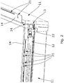
- Fig. 2 the corner assembly of the insulation frame can be seen in more detail and provides a better view of the flange 14 of the supporting rails 12.
- the flange 14 is provided with openings and holes 21 suitable for allowing the insulating frame to be secured to a roof structure by screws, nails or other like fasteners, but this need not be the case.
- the supporting rails 12 are secured in the hollow connecting sections 22 of each leg of the connector brackets 13.
- the connecting sections 22 have an angular cross-sectional shape, matching the supporting rails 12, resulting in a rigid connection. It is also visible how the connector bracket 13 is able to fit into a groove 24 of an insulating element 11, allowing different arrangements of insulating elements to be used.
- Assembling the supporting frame requires the provision of a plurality of supporting rails 12 and a plurality of double-walled connector brackets 13 with a hollow cross-section.
- Each connector bracket 13 being made from a polymer, and each connector bracket including two bracket connecting sections 22.
- Each connecting section 22 of each connector bracket 13 is then connected to a supporting rail 12 by inserting an end portion of the supporting rail 12 serving as a rail connecting section in the hollow cross-section of each bracket connecting section 22 of each connector bracket 13 as seen by comparing Figs 3 and 4 , thereby forming an insulating frame.
- Figs 4-7 provides a view of the plurality of recesses and/or openings 31 provided in the connector bracket 13, which allow items, such as electrical wiring or electrical or mechanical sensors to pass through the bracket and/or form items to be attached to the bracket. Furthermore, the recesses and/or openings 31 reduce the overall material required to manufacture the connector bracket 13, while preserving the strength and stiffness of the connector bracket as well as reducing the thermal conductivity and facilitating automated handling by machinery.
- Fig. 4 and 5 also highlight how the connector bracket 13 can function as a corner bracket, by connecting two supporting rails 12 substantially perpendicular to each other.
- Figs 3-5 show how the L-shaped cross-section of the supporting rail 12, i.e. two angular portions of the cross-section of the supporting rail 12, which are normal to the length direction L, as shown in Fig. 4 , of the supporting rail 12, each having a longitudinal direction perpendicular to each other and to the length direction of the supporting rail 12, connects with the connecting section 22 of the connector bracket 13.
- the L-shaped cross-section improves the strength of the connection and ensures that the parts are positioned correctly in relation to each other.
- the double-walled and hollow L-shaped cross-section 51 of the connecting section 22, with which the supporting rail engages, is best seen in Fig. 6 .
- the circumference of the hollow L-shaped cross-section 51 is fully closed over at least a portion of the connecting sections 22 length direction, but the term "double-walled” does not mean that this has to be case.
- connection between the supporting rail 12 and connector bracket 13 is facilitated by snap locking, with a barb 52, best seen in Fig. 6 and 7 , in the connecting section 22 adapted for being bent back during insertion of a supporting rail 12 and snapping into an opening in the supporting rail.
- a tactile feedback is provided when the supporting rail 12 is inserted to the correct depth in the connecting section 22, such that the installer is aware when the components have been connected properly.
- the barb 52 snapping into the opening may also result in a sound, which may serve as an audio feedback to the installer, telling him that the intended engagement has been achieved.
- Fig. 8 shows another embodiment where the connector bracket 70 is used as an extension piece, connecting supporting rails 12 arranged in longitudinal continuation of each other, thereby allowing supporting frames of different dimensions to be created from standard length supporting rails.
- This connector bracket 70 further comprises a flange portion 71, which is here shown as an uninterrupted plate, but which could also be provided with one or more holes (not shown) allowing for a fastener to be inserted through the flange and into a part of the roof structure as described above with reference to the flanges 14 on the supporting rails.
- the flange portion 71 acting as a further support or fastening point between the insulating frame and the roof structure, the rigidity and stiffness of the mounted insulating frame is further improved, thereby preventing the insulating frame from being locally displaced at the interconnection between the supporting rails. Securing the flange portion 71 to a part of the roof structure, then becomes part of the assembly method of the insulation frame.
- Fig. 9 and 10 provide a better view of this embodiment of the connector bracket 70 with a flange portion 71 and the ability to connect supporting rails in longitudinal continuation of each other. Again this embodiment also features a plurality of recesses and/or openings 31, allowing items to pass through or be attached to the connector and/or reduce the thermal conductivity and/or material consumption.
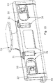
- Figures 11 and 12 show a third embodiment where the connector bracket 100 comprises an attachment device 101.
- the attachment device 101 projects from the outer surface of the corner of the connector bracket 13.
- the attachment device 101 comprises an indent 102 suitable for receiving a stabilizing element, such as a string, cord or the like.
- the stabilizing element may be secured to the indent 102 by looping it or tying it around the attachment device such that a section of it is arranged in the indent 102.
- the stabilizing element may be secured in the cavity 111 of the attachment device 101 which comprises a plurality of barbs, adapted to secure the stabilizing element.
- the geometry of the attachment devices 101 may be different from connector bracket 100 to connector bracket 100 and may feature an indent 102 or a cavity 111, or both.
- Attaching a stabilizing element between attachment devices 101 of opposite corners of an supporting frame provides an indication of whether the frame has been assembled correctly.
- a stabilizing element with a length corresponding to the length between the attachment devices 101 in a correctly assembled insulating frame, between which it is attached, the insulating frame may be deemed to have been incorrectly assembled if the length of the stabilizing element is too short or too long, and correctly assembled if the length of the stabilizing element matches the length between the corresponding attachment devices 101.
- a stabilizing element comprising indicators and/or markings
- correct assembly of the insulating frame may be determined from the alignment of the indicators and/or markings of the stabilizing element with the indicators and/or markings (not shown) of the attachment device 101.
- the thus stabilized insulating frame is better suited for being used as template for cutting holes in a roof suitable for a window frame.
- Preferably two stabilising elements are attached between opposite corners of the insulating frame for formation of a cross.
- the attachment device 101 is here made from the same polymer as the rest of the connector bracket, preferred due to its stiffness and cost of production. In other embodiments, it may of course be made from other materials such as metals or polymers. The material choice is in principle independent of the shape of the attachment device 101, but strength and thermal conductivity should be taken into account. Attachment devices may also be provided as separate add-on parts, which can be added to connector brackets as the one shown in Figs 1-10 .
- a flange 72 similar to the flange 71 described with reference to Figs 8-10 has been indicated in dotted lines.
- This flange 72 serve the same purpose as described above with reference to flange 71. If the corner connector brackets of a supporting frame are all provided with such flanges 72, the flanges 14 on the supporting rails 12 may be reduced in size or potentially left out entirely.
- flanges 71, 72 on the connector brackets must be positioned such that they give room for mounting brackets used for connecting the frame (not shown) of the roof window to the roof structure. For this reason, their size and shape may also vary from what is shown in the drawing.
Landscapes
- Engineering & Computer Science (AREA)
- Architecture (AREA)
- Civil Engineering (AREA)
- Structural Engineering (AREA)
- Roof Covering Using Slabs Or Stiff Sheets (AREA)
Abstract
Description
- The present invention relates to a supporting frame for an insulating frame for a roof window, said supporting frame comprising top, bottom and side supporting rails, where one or more supporting rails are configured to carry insulating elements, each supporting rail comprising one or more rail connecting sections, and where said supporting frame further comprises a plurality of connector brackets, each of said connector brackets comprising two bracket connecting sections each connected to a rail connecting section of a supporting rail. The invention further relates to a method of assembling a supporting frame for an insulating frame for a roof window.
- An insulating frame for insulating the interface between a roof window and an inclined roof structure, in which the window is installed, is known from
EP2677092A1 . This insulating frame includes supporting rails extending along insulating elements and connector brackets used for interconnecting the supporting rails, thereby forming the insulating frame. It has proven to provide advantages over the previously known insulating frames as this frame can be assembled in-situ and is thus easier to handle for the installer. However, the stability of the insulating frame has been found to be insufficient in some installation situations, and it is further desired to reduce the production cost of the insulating frame. - It is therefore the object of the invention to provide a supporting frame for an insulating frame which contributes to improving the stability of the insulating frame and which preferably also makes the insulating frame cheaper to produce.
- According to a first aspect of the invention this is achieved with a supporting frame for an insulating frame for a roof window as described above, where each of said connector brackets detachably interconnects two supporting rails so that the respective supporting rails are perpendicular to each other or interconnects two supporting rails in longitudinal continuation of each other, and where each of the connector brackets is double-walled with a hollow cross-section at the connecting sections, the hollow cross-section accommodating the rail connecting section, and where the connector bracket is made from a polymer.
- By making the connector bracket as a double-walled polymer structure, the rigidity of the connector bracket is increased without increasing the thermal conductivity of the insulating frame.
- Moreover, by the connector bracket being double-walled and hollow the connector bracket is allowed to act as a female connector, which may result in material savings as the supporting rails can be made with a simple single-walled cross-sectional shape. This may reduce the complexity of the production process of the supporting rails, thus potentially increasing efficiency and lowering production costs of the insulating frame.
- The term "double-walled" is intended to mean that at least the parts of the connector bracket serving as connecting sections must comprise walls forming a space between them, which is suitable for accommodating a connecting section of a supporting rail. The space does not have to be closed and parts of the cross-section can be single-walled, for example to allow the use with different types of supporting rails or to allow access to an engagement mechanism adapted for securing the connection between the connector bracket and the supporting rail.
- The term "in longitudinal continuation of each other" should be understood as the supporting rails being interconnected in their length direction such that their respective longitudinal axes are substantially collinear. This may allow the connector bracket to function as an extension piece in the supporting frame and so allow the dimensions of the supporting frame to be altered to a desired magnitude by interconnecting one or more supporting rails in longitudinal or lengthwise continuation of each other.
- The term "detachably interconnect" should be understood as the rail connecting section and the bracket connecting sections may be detached from each other after being interconnected without unintended substantial damage i.e. in a non-destructive manner.
- This facilitates a simple and easy assembly of the supporting frame. Furthermore, this facilitates a non-destructive disassembly of the supporting frame through the detachably interconnected connecting sections.
- The supporting rails may be made from a polymer in order to decrease costs and reduce thermal conductivity.
- In one embodiment the bracket connecting sections comprise a projection, recess and/or opening adapted for snap locking with a corresponding projection, recess and/or opening on a rail connecting section. This may allow or facilitate snap locking between the supporting rails and the connector brackets, which may improve the ease of assembly of the supporting frame.
- In an embodiment the rail connecting sections or bracket connecting sections comprise a barb which is in engagement with a corresponding opening in the counterpart connecting section with which it is interconnected. The connection between the barb and the opening may be releasable for example by making the barb or a tab on which it is provided from an elastic material. This may facilitate the interconnected rail connecting sections and bracket connecting sections to be detached from each other in a non-destructive manner i.e. a detachable interconnection.
- A second aspect of the invention concerns an insulating frame for a roof window comprising the supporting frame according to the first aspect of the invention, where each supporting rail of said supporting frame carries an insulating element. It is, however, also possible to leave one or more supporting rails or part(s) thereof without insulation.
- A third aspect of the invention concerns a connector bracket configured for use in a supporting frame according the first aspect of the invention.
- In a first embodiment the connector bracket has an angular cross-sectional shape, preferably an L-shape, at each connecting section, which may provide strength and stiffness as will be described below.
- In a second embodiment the connector bracket comprises a flange portion adapted for securing the insulating frame to a roof structure. This may help keep the supporting frame in position as will be described below.
- In a third embodiment, the connector bracket configured for use in a supporting frame according the first aspect of the invention, further comprising an attachment device adapted for securing a rod, cord, string, or the like. This may help to maintain the intended shape of the supporting frame during installation and/or to confirm correct assembly of the frame as will be described below.
- A fourth aspect of the invention concerns a kit for making a supporting frame for an insulating frame for a roof window according to the first aspect of the invention, including a plurality of top, bottom and side supporting rails and a plurality of connector brackets.
- This may provide the installer with a convenient package comprising the necessary parts for assembling a supporting frame.
- A fifth aspect of the invention concerns a method of assembling a supporting frame, comprising the steps of:
- providing one or more top, bottom and side supporting rails, each supporting rail comprising one or more rail connecting sections,
- providing a plurality of connector brackets, each connector bracket including two bracket connecting sections, being double-walled with a hollow cross-section at the connecting sections, and being made from a polymer,
- interconnecting each bracket connecting section of each connector bracket to a rail connecting section of a supporting rail so that the hollow cross-section of the connector bracket accommodates the rail connecting section, thereby forming a supporting frame.
- In a development of the previous embodiment the method further comprises the step of:
- attaching one or more insulating elements to said supporting rails.
- In this way an insulating frame for a roof window may be assembled if so desired.
- In an embodiment of the fifth aspect of the invention, the method further comprises securing a flange portion of at least one connector bracket to a roof structure.
- A connector bracket, which contributes to improving the stability of a supporting frame and which preferably also makes it cheaper to produce is achieved with a connector bracket, which is double-walled with a hollow cross-section at the connecting sections, the hollow cross-section being adapted to accommodate a supporting rail, and where the connector bracket is made from a polymer.
- By making the connector bracket as a double-walled polymer structure, the rigidity of the connector bracket is increased without increasing the thermal conductivity of the insulating frame.
- Moreover, by the connector bracket being double-walled and hollow the connector bracket is allowed to act as a female connector, which may result in material savings as the supporting rails can be made with a simple single-walled cross-sectional shape. This may reduce the complexity of the production process of the supporting rails, thus potentially increasing efficiency and lowering production costs of the insulating frame.
- In one embodiment said connector bracket is made as an angular bracket having two legs, which are substantially perpendicular to each other and each comprising a connecting section. This makes the connector bracket suitable for use at corners of the insulating frame so that the supporting rails can be relatively simple with a substantially continuous cross-sectional shape over their entire length. However, the connector bracket may also be used for interconnecting insulating elements arranged in continuation of each other, for example serving as an extension piece.
- In one embodiment the connector bracket has an angular cross-sectional shape, preferably an L-shape, at each connecting section. This allows the connector bracket to be connected to supporting rails having an angular cross-sectional shape perpendicular to their length direction. Such supporting rails are presently considered advantageous as they have good bending resistance. The supporting rails may be made from any suitable material selected from the group consisting of: steel, stainless steel, aluminium, other metals, polymers, ceramics, glass fibre, composites and combinations thereof.
- In order to reduce the material consumption and/or optimize the strength and stiffness of the connector bracket, it may comprise a plurality of recesses and/or openings. Such recesses or openings may also serve other purposes, such as allowing other items to pass through the connector bracket or be attached to it, or further reducing the thermal conductivity of the connector bracket, or facilitating automated handling of the connector bracket.
- The connector bracket should be made from a material of a dimensionally stable nature having good thermal insulating properties and rigidity, such as polyethylene, polypropylene, polyurethane, polyvinylchloride, polycaprolactam or acrylonitrile butadiene styrene.
- In order to facilitate the connection to the supporting rails, the connecting sections may comprise a projection, recess and/or opening adapted for snap locking with a corresponding projection, recess and/or opening on a supporting rail of an insulating element of an insulating frame. In one embodiment, each connecting section of the connector bracket includes a barb adapted for being bent back during insertion of the supporting rail in the hollow between the double walls and for snapping into an opening in the supporting rail, when the supporting rail has been inserted to the correct depth. It will also be possible to provide the supporting rail with a barb and the connector bracket with a matching opening, to provide both with barbs, or any other combination of matching projections, recesses and/or openings allowing an interconnection. In a presently preferred embodiment the engagement between the connecting section and the supporting rail provides a tactile and/or audio feedback to the installer so that he/she knows when the engagement has been established.
- The connector bracket may comprise a flange portion adapted for securing the insulating frame to a roof structure thereby facilitating the installation of the insulating frame. Particularly when the connector bracket is used for interconnecting insulating elements arranged in continuation of each other, such a flange portion may also serve to support the insulating frame and prevent sagging. The flange portion may be provided with one or more holes or recesses allowing a screw or like fastener to be inserted through the flange and into a part of the roof structure, such as a lath.
- The connector bracket may further comprise an attachment device adapted for allowing a stabilizing element to be attached to the connector bracket. This provides the advantage that the insulating frame may be further stabilized by attaching a stabilizing element between two connector brackets using the attachment devices as attachment points, improving handling and installation of the insulating frame. If a stabilizing element, with a length corresponding to the length between the connector brackets in a correctly assembled insulation frame, is used, it may be used to determine whether the insulating frame has been assembled correctly. If the insulating frame is assembled correctly, the length of the stabilizing element will match the length between the corresponding connector brackets between which it attaches. If the length of the stabilizing element is too short or too long compared to the length between the corresponding connector brackets, the insulating frame has not been assembled correctly. In a rectangular insulating frame the stabilizing element is preferably arranged diagonally so that it extends between connector brackets at opposite corners of the frame.
- Further stabilization still may be achieved by attaching two stabilizing elements to connector brackets at opposite corners of the frame using the attachment devices as attachment points such that the stabilizing elements cross each other at the centre of the frame.
- The stabilizing elements may be in the form of a rod made from a rigid material such as a metal, polymer, wood or cardboard. The stabilizing elements could also be in the form of a cord or string or the like, made from a material such as a polymer, metal or cardboard. The stabilizing elements may be part of the packaging used for the connector brackets or insulating frame, such as for example in the form of a tear-off piece of the packaging. This provides the advantage of reduced waste material and improved packaging efficiency as the stabilizing elements need not be provided separately.
- To ensure correct attachment, the stabilizing elements may feature indicators and/or markings indicating the correct length and/or point of attachment. This facilitates attaching the stabilizing elements. The stabilizing elements may provide a visual indication of whether the insulating frame has been assembled correctly e.g. when a stabilizing element does not attach or the indicator or marking does not align correctly with an attachment device, or there is slack in an attached stabilizing element.
- The attachment devices may exhibit different geometries. That is, the geometry of attachment devices may differ such that the attachment device of connector brackets arranged at the top, bottom or sides of the insulating frame may differ in geometry. This provides the advantage, that during assembly of an insulating frame, the location of attachment of a connector bracket may be determined from the geometry of the attachment devices, improving ease of assembly. Furthermore, the geometry of the attachment devices may be used as indicators for orientating the insulating frame correctly during installation, improving ease of installation.
- The attachment device may comprise an indent adapted for receiving a stabilizing element and/or a cavity with a plurality of barbs adapted to secure a stabilizing element, or both. The attachment device may further comprise indicators and/or markings to align with corresponding indicators and/or markings on the stabilizing elements, providing an improved visual indication of whether the insulating frame has been correctly assembled.
- Given the improved dimensional stability with stabilizing elements attached, the handling of the insulating frame is improved. Furthermore it may be used as a template for cutting a hole in roof suitable for a window frame.
- Regardless of the design of the connector brackets, the insulating elements are preferably made from a material of a dimensionally stable nature having good thermal insulating properties, preferably a polymer foam, such as extruded polyethylene (PE), polypropylene (PP), polyurethane (PU), polyvinylchloride (PVC), expanded polystyrene (EPS), extruded polystyrene (XPS) or mineral wool.
- Details of the embodiments and aspects described above may be combined unless otherwise stated.
- In the following the invention will be described in more detail with reference to the schematic drawings, where
-
Fig. 1 is a perspective view of an assembled insulating frame comprising a supporting frame according to the invention and insulating elements,Fig. 2 is an enlarged view of the detail marked AA inFig. 1 , -
Fig. 3 is an enlarged view ofFig. 2 from a different perspective where the insulating elements have been removed and the supporting rail and connector bracket are disconnected, -
Fig. 4 provides an outer perspective view of the detail inFig. 2 without the insulating elements, -
Fig. 5 provides an inner perspective of the detail inFig. 4 , -
Fig. 6 is an enlarged inner perspective view of the connector bracket inFigs 1-5 , -
Fig. 7 is an outer perspective view of the connector bracket inFig. 6 where the connector bracket has been turned upside-down, -
Fig. 8 is an outer perspective view of a second embodiment of a connector bracket connecting supporting rails arranged in longitudinal continuation of each other, -
Fig. 9 is an enlarged inner perspective view of the connector bracket inFig. 8 , -
Fig. 10 is an outer perspective view of the connector bracket inFig. 9 , -
Fig. 11 is a perspective view of a connector bracket with a hook, and -
Fig. 12 is an outer view of the connector bracket inFig. 11 . - A supporting frame for an insulating frame will now be described with reference to
Fig.1 . - An insulating frame like the one in
Fig.1 is typically installed in a suitable opening in a roof structure. The insulating frame provides an insulating barrier at the interface between the roof window and the roof structure, as well as facilitating easier mounting of the roof window by providing a predefined space adapted for the window. The frame can be delivered as a complete kit for assembly including a plurality of insulatingelements 11, a plurality of supportingrails 12 and a plurality ofconnector brackets 13, providing a convenient solution for the installer. The insulating frame has an exterior side adapted to face away from the interior of the building, and an interior side adapted for facing towards the interior of the building. An insulating frame like this, that can be efficiently assembled and adapted to a given window in-situ is highly advantageous to the installer, but it may also be delivered in an assembled state as can the supporting frame. - The insulating frame comprises top, bottom and
side supporting rails 12 as well as insulatingelements 11, which refer to their location when mounted, andconnector brackets 13 as will be discussed in more detail below. The insulatingelements 11 define an inner opening and an outer border. The inner opening comprising aledge 15 projecting towards the inner opening, which is intended to project underneath a frame of the roof window, and the outer border is intended to face the opening in the roof structure. The insulatingelements 11, which make up the majority of the volume of the insulating frame, are made from a material of a dimensionally stable nature having good thermal insulating properties combined with a softer material, which is compressible so as to allow it to yield and adapt to the shape of the opening in the roof structure, further details and of this are described in the applicants granted patentEP2677092B1 . In this embodiment the insulatingelements 11 are made from two types polymer foam. It is, however, also possible to make the insulating elements from a single material, or for the insulating elements to be made from different materials or combinations of materials. - In the embodiment shown the supporting
rails 12, which together with theconnector brackets 13 make up the supporting frame, are attached by interconnecting therail connecting sections 23 with respectivebracket connecting sections 22 of theconnector brackets 13 as best seen inFig. 3 . Here abarb 52 of abracket connecting section 22 interconnects with arail connecting section 23 of a supportingrail 12 by engaging with acorresponding opening 32 in saidrail connecting section 23. Thebarb 52 effectively snaps into theopening 32. This is achieved by inserting the supportingrail 23 into thebracket connecting section 22, the cross-section of which is better seen inFig. 6 , whereby thebarb 52 is deflected by the side of the supportingrail 12 until thebarb 52 reaches theopening 32 and snaps into theopening 32.Figs. 4 and5 shows the supportingrails 12 andconnector bracket 13 ofFig. 3 in an interconnected state i.e. a state where thebarbs 52 of thebracket connecting sections 22 of theconnector bracket 13 are engaged with the respective openings in therail connecting sections 23 of the supporting rails 12. As is presently preferred in regard to the stability of the supporting frame, therail connecting section 23 and supportingrail 12 shown here have an angular L-shaped cross-section configure to match the hollow cross-section of thebracket connecting section 22 of theconnector bracket 13, however, this need not be the case and the cross-section of both the supportingrail 12 and therail connecting section 23 may be of any suitable shape, such as for example a simple straight profile. Similarly, theconnector bracket 13 may be of any suitable corresponding shape. - As is also seen here, the
rail connecting section 23 acts as the male interconnecting part and the bracket connecting section acts as the female interconnecting counterpart part. This, however, may also be the other way around with therail connecting section 23 acting as the female interconnecting counterpart and thebracket connecting section 22 acting as the male interconnecting counterpart. This applies independent of the other features of the rails and brackets shown in the drawing. - In the embodiments shown, the insulating elements are attached to the sides of the supporting rails 12. Each supporting
rail 12 extends substantially along the insulatingelements 11 length, and each supportingrail 12 features aflange 14, which projects beyond the outer face of the insulatingelement 11. Securing the flange to the roof structure has the advantage that the insulating frame is not unintentionally pushed downwards into the roof structure, when the roof window is mounted. - The supporting rails 12 are here made from steel, preferred due to its stiffness and strength, but in other embodiments they may be made from aluminium or a polymer. The choice of material is in principle independent of the shape of the rail, but thermal conductivity, strength etc. should of course be taken into consideration.
- In the embodiment in
Figs 1-7 theconnector brackets 13 are each in the form of an angular bracket, wherein the two connectingsections 22 of eachconnector bracket 13 form part of two legs, which are substantially perpendicular to each other. Theconnector brackets 13 each connect two supportingrails 12 of corresponding insulating elements at each corner of the insulating frame, this is better seen inFig. 4 &5 . - The
connector brackets 13 are here made from a polymer, which reduces the overall cost of production and reduces the thermal conductivity, whilst maintaining important performance properties such as stiffness and rigidity due to the double-walled design, which will be described below. - In
Fig. 2 , the corner assembly of the insulation frame can be seen in more detail and provides a better view of theflange 14 of the supporting rails 12. As may be seen, theflange 14 is provided with openings and holes 21 suitable for allowing the insulating frame to be secured to a roof structure by screws, nails or other like fasteners, but this need not be the case. - The supporting rails 12 are secured in the hollow connecting
sections 22 of each leg of theconnector brackets 13. The connectingsections 22 have an angular cross-sectional shape, matching the supportingrails 12, resulting in a rigid connection. It is also visible how theconnector bracket 13 is able to fit into agroove 24 of an insulatingelement 11, allowing different arrangements of insulating elements to be used. - Assembling the supporting frame requires the provision of a plurality of supporting
rails 12 and a plurality of double-walled connector brackets 13 with a hollow cross-section. Eachconnector bracket 13 being made from a polymer, and each connector bracket including twobracket connecting sections 22. Each connectingsection 22 of eachconnector bracket 13 is then connected to a supportingrail 12 by inserting an end portion of the supportingrail 12 serving as a rail connecting section in the hollow cross-section of eachbracket connecting section 22 of eachconnector bracket 13 as seen by comparingFigs 3 and4 , thereby forming an insulating frame. - Moving to
Figs 4-7 provides a view of the plurality of recesses and/oropenings 31 provided in theconnector bracket 13, which allow items, such as electrical wiring or electrical or mechanical sensors to pass through the bracket and/or form items to be attached to the bracket. Furthermore, the recesses and/oropenings 31 reduce the overall material required to manufacture theconnector bracket 13, while preserving the strength and stiffness of the connector bracket as well as reducing the thermal conductivity and facilitating automated handling by machinery.Fig. 4 and5 also highlight how theconnector bracket 13 can function as a corner bracket, by connecting two supportingrails 12 substantially perpendicular to each other. - In combination
Figs 3-5 show how the L-shaped cross-section of the supportingrail 12, i.e. two angular portions of the cross-section of the supportingrail 12, which are normal to the length direction L, as shown inFig. 4 , of the supportingrail 12, each having a longitudinal direction perpendicular to each other and to the length direction of the supportingrail 12, connects with the connectingsection 22 of theconnector bracket 13. The L-shaped cross-section improves the strength of the connection and ensures that the parts are positioned correctly in relation to each other. The double-walled and hollow L-shapedcross-section 51 of the connectingsection 22, with which the supporting rail engages, is best seen inFig. 6 . In this embodiment the circumference of the hollow L-shapedcross-section 51 is fully closed over at least a portion of the connectingsections 22 length direction, but the term "double-walled" does not mean that this has to be case. - In this embodiment the connection between the supporting
rail 12 andconnector bracket 13 is facilitated by snap locking, with abarb 52, best seen inFig. 6 and7 , in the connectingsection 22 adapted for being bent back during insertion of a supportingrail 12 and snapping into an opening in the supporting rail. In the presently preferred embodiment, a tactile feedback is provided when the supportingrail 12 is inserted to the correct depth in the connectingsection 22, such that the installer is aware when the components have been connected properly. Thebarb 52 snapping into the opening may also result in a sound, which may serve as an audio feedback to the installer, telling him that the intended engagement has been achieved. - In the following, items having the same or analogue function as described with reference to
Figs. 1-7 will be given the same reference numbers even though they may not be identical to the items shown inFig. 1 . -
Fig. 8 shows another embodiment where theconnector bracket 70 is used as an extension piece, connecting supportingrails 12 arranged in longitudinal continuation of each other, thereby allowing supporting frames of different dimensions to be created from standard length supporting rails. Thisconnector bracket 70 further comprises aflange portion 71, which is here shown as an uninterrupted plate, but which could also be provided with one or more holes (not shown) allowing for a fastener to be inserted through the flange and into a part of the roof structure as described above with reference to theflanges 14 on the supporting rails. By theflange portion 71 acting as a further support or fastening point between the insulating frame and the roof structure, the rigidity and stiffness of the mounted insulating frame is further improved, thereby preventing the insulating frame from being locally displaced at the interconnection between the supporting rails. Securing theflange portion 71 to a part of the roof structure, then becomes part of the assembly method of the insulation frame. -
Fig. 9 and10 provide a better view of this embodiment of theconnector bracket 70 with aflange portion 71 and the ability to connect supporting rails in longitudinal continuation of each other. Again this embodiment also features a plurality of recesses and/oropenings 31, allowing items to pass through or be attached to the connector and/or reduce the thermal conductivity and/or material consumption. - The interconnection of the supporting
rails 12 and theconnector bracket 70 inFigs 8-10 is the same as described above with reference toFigs 1-7 , including the embodiments of the connecting sections. -
Figures 11 and12 show a third embodiment where theconnector bracket 100 comprises anattachment device 101. Theattachment device 101 projects from the outer surface of the corner of theconnector bracket 13. Theattachment device 101 comprises anindent 102 suitable for receiving a stabilizing element, such as a string, cord or the like. The stabilizing element may be secured to theindent 102 by looping it or tying it around the attachment device such that a section of it is arranged in theindent 102. Alternatively, or as a supplement, the stabilizing element may be secured in thecavity 111 of theattachment device 101 which comprises a plurality of barbs, adapted to secure the stabilizing element. The geometry of theattachment devices 101 may be different fromconnector bracket 100 toconnector bracket 100 and may feature anindent 102 or acavity 111, or both. - Attaching a stabilizing element between
attachment devices 101 of opposite corners of an supporting frame provides an indication of whether the frame has been assembled correctly. Using a stabilizing element, with a length corresponding to the length between theattachment devices 101 in a correctly assembled insulating frame, between which it is attached, the insulating frame may be deemed to have been incorrectly assembled if the length of the stabilizing element is too short or too long, and correctly assembled if the length of the stabilizing element matches the length between thecorresponding attachment devices 101. If a stabilizing element comprising indicators and/or markings is used, correct assembly of the insulating frame may be determined from the alignment of the indicators and/or markings of the stabilizing element with the indicators and/or markings (not shown) of theattachment device 101. Furthermore, it improves the dimensional stability and overall rigidity of the frame, allowing better handling and improving the ease of mounting. Furthermore, the thus stabilized insulating frame is better suited for being used as template for cutting holes in a roof suitable for a window frame. Preferably two stabilising elements are attached between opposite corners of the insulating frame for formation of a cross. - The
attachment device 101 is here made from the same polymer as the rest of the connector bracket, preferred due to its stiffness and cost of production. In other embodiments, it may of course be made from other materials such as metals or polymers. The material choice is in principle independent of the shape of theattachment device 101, but strength and thermal conductivity should be taken into account. Attachment devices may also be provided as separate add-on parts, which can be added to connector brackets as the one shown inFigs 1-10 . - In
Fig. 11 the presence of aflange 72 similar to theflange 71 described with reference toFigs 8-10 has been indicated in dotted lines. Thisflange 72 serve the same purpose as described above with reference toflange 71. If the corner connector brackets of a supporting frame are all provided withsuch flanges 72, theflanges 14 on the supportingrails 12 may be reduced in size or potentially left out entirely. - It is noted that
flanges - In the above, the inventive concept has been described with reference to a few embodiments. However, as is readily appreciated by a person skilled in the art, other embodiments than the ones disclosed above are equally possible within the scope of the inventive concept, as defined by the appended claims.
-
- 11
- Insulating element
- 12
- Supporting rail
- 13
- Connector bracket
- 14
- Flange
- 15
- Ledge
- 21
- Openings and holes
- 22
- Bracket connecting section
- 23
- Rail connecting section
- 24
- Groove
- 31
- Recesses and/or openings
- 32
- Opening
- 51
- Hollow L-shaped cross section
- 52
- Barb
- 70
- Connector bracket
- 71
- Flange portion
- 72
- Flange portion
- 100
- Connector bracket
- 101
- Attachment device
- 102
- Indent
- 111
- Cavity
Claims (11)
- A supporting frame for an insulating frame for a roof window, said supporting frame comprising top, bottom and side supporting rails, where one or more supporting rails are configured to carry insulating elements, each supporting rail comprising one or more rail connecting sections,
said supporting frame further comprising a plurality of connector brackets, each of said connector brackets comprising two bracket connecting sections each connected to a rail connecting section of a supporting rail,
where each of said connector brackets detachably interconnects two supporting rails so that the respective supporting rails are perpendicular to each other or interconnects two supporting rails in longitudinal continuation of each other, and
where each of the connector brackets is double-walled with a hollow cross-section at the connecting sections, the hollow cross-section accommodating the rail connecting section, and where the connector bracket is made from a polymer. - The supporting frame according to claim 1, where the bracket connecting sections comprise a projection, recess and/or opening adapted for snap locking with a corresponding projection, recess and/or opening on a rail connecting section.
- The supporting frame according to claim 1 or 2, where a rail connecting section or a bracket connecting section comprises a barb which is in engagement with a corresponding opening in the counterpart connecting section with which it is interconnected.
- An insulating frame for a roof window comprising the supporting frame according to one or more of claims 1-3, where each supporting rail of said supporting frame carries an insulating element.
- A connector bracket configured for use in a supporting frame according to one or more of the preceding claims having an angular cross-sectional shape, preferably an L-shape, at each connecting section.
- A connector bracket configured for use in a supporting frame according to one or more of the preceding claims, where the connector bracket comprises a flange portion adapted for securing the insulating frame to a roof structure.
- A connector bracket configured for use in a supporting frame according to one or more of the preceding claims, further comprising an attachment device adapted for securing a rod, cord, string, or the like.
- A kit for making a supporting frame for an insulating frame for a roof window according to any of the preceding claims, including a plurality of top, bottom and side supporting rails and a plurality of connector brackets.
- A method of assembling a supporting frame, comprising the steps of:- providing one or more top, bottom and side supporting rails, each supporting rail comprising one or more rail connecting sections,- providing a plurality of connector brackets, each connector bracket including two bracket connecting sections, being double-walled with a hollow cross-section at the connecting sections, and being made from a polymer,- interconnecting each bracket connecting section of each connector bracket to a rail connecting section of a supporting rail so that the hollow cross-section of the connector bracket accommodates the rail connecting section, thereby forming a supporting frame.
- A method according to claim 9, further comprising the step of:- attaching one or more insulating elements to said supporting rails.
- A method according to claim 9 or 10, further comprising securing a flange portion of at least one connector bracket to a roof structure.
Priority Applications (1)
| Application Number | Priority Date | Filing Date | Title |
|---|---|---|---|
| PL18248013T PL3533947T3 (en) | 2017-12-27 | 2018-12-27 | A supporting frame for an insulating frame for a roof window and a method of assembling a supporting frame |
Applications Claiming Priority (1)
| Application Number | Priority Date | Filing Date | Title |
|---|---|---|---|
| DKPA201771027 | 2017-12-27 |
Publications (2)
| Publication Number | Publication Date |
|---|---|
| EP3533947A1 true EP3533947A1 (en) | 2019-09-04 |
| EP3533947B1 EP3533947B1 (en) | 2022-01-26 |
Family
ID=65011761
Family Applications (1)
| Application Number | Title | Priority Date | Filing Date |
|---|---|---|---|
| EP18248013.7A Active EP3533947B1 (en) | 2017-12-27 | 2018-12-27 | A supporting frame for an insulating frame for a roof window and a method of assembling a supporting frame |
Country Status (4)
| Country | Link |
|---|---|
| EP (1) | EP3533947B1 (en) |
| DE (1) | DE202018006297U1 (en) |
| HU (1) | HUE058051T2 (en) |
| PL (1) | PL3533947T3 (en) |
Cited By (2)
| Publication number | Priority date | Publication date | Assignee | Title |
|---|---|---|---|---|
| DE102020209060A1 (en) | 2020-07-20 | 2022-01-20 | Roto Frank Dachsystem-Technologie GmbH | Installation frame for installing a roof window, roof window assembly, roof assembly and method for installing a roof window |
| EP4023832A1 (en) | 2020-12-30 | 2022-07-06 | VKR Holding A/S | A roof window system with an insulating frame |
Families Citing this family (2)
| Publication number | Priority date | Publication date | Assignee | Title |
|---|---|---|---|---|
| DE102023107172A1 (en) * | 2023-03-22 | 2024-09-26 | Lamilux Heinrich Strunz Gmbh | Base frame module for roof windows |
| AT528222B1 (en) * | 2024-07-09 | 2025-11-15 | Fixotherm Fensterbank Dichtsysteme Gmbh | Device for installing a roof window |
Citations (5)
| Publication number | Priority date | Publication date | Assignee | Title |
|---|---|---|---|---|
| WO2000068540A1 (en) * | 1999-05-06 | 2000-11-16 | Valderrama, Maria, Teresa | Assembly system for thermoacoustic windows |
| US7624547B1 (en) * | 2008-07-21 | 2009-12-01 | Vkr Holding A/S | Accessory kit for a fixed curb-mounted skylight |
| EP2677092A1 (en) | 2012-06-19 | 2013-12-25 | VKR Holding A/S | An insulating frame for a roof window and a method of mounting a roof window |
| WO2014102558A1 (en) * | 2012-12-31 | 2014-07-03 | Vargas Osorno Mariela | Ready-to-assemble modular frames and windows and doors made using said system |
| EP2947219A1 (en) * | 2014-05-22 | 2015-11-25 | Roto Frank Ag | Installation element for a roof window, roof window and method for installing a roof window |
Family Cites Families (1)
| Publication number | Priority date | Publication date | Assignee | Title |
|---|---|---|---|---|
| US4462186A (en) * | 1982-11-22 | 1984-07-31 | Fuller Leroy C | Self-adjusting window unit with corner assembly |
-
2018
- 2018-12-27 DE DE202018006297.9U patent/DE202018006297U1/en active Active
- 2018-12-27 HU HUE18248013A patent/HUE058051T2/en unknown
- 2018-12-27 PL PL18248013T patent/PL3533947T3/en unknown
- 2018-12-27 EP EP18248013.7A patent/EP3533947B1/en active Active
Patent Citations (6)
| Publication number | Priority date | Publication date | Assignee | Title |
|---|---|---|---|---|
| WO2000068540A1 (en) * | 1999-05-06 | 2000-11-16 | Valderrama, Maria, Teresa | Assembly system for thermoacoustic windows |
| US7624547B1 (en) * | 2008-07-21 | 2009-12-01 | Vkr Holding A/S | Accessory kit for a fixed curb-mounted skylight |
| EP2677092A1 (en) | 2012-06-19 | 2013-12-25 | VKR Holding A/S | An insulating frame for a roof window and a method of mounting a roof window |
| EP2677092B1 (en) | 2012-06-19 | 2015-07-22 | VKR Holding A/S | An insulating frame for a roof window and a method of mounting a roof window |
| WO2014102558A1 (en) * | 2012-12-31 | 2014-07-03 | Vargas Osorno Mariela | Ready-to-assemble modular frames and windows and doors made using said system |
| EP2947219A1 (en) * | 2014-05-22 | 2015-11-25 | Roto Frank Ag | Installation element for a roof window, roof window and method for installing a roof window |
Cited By (2)
| Publication number | Priority date | Publication date | Assignee | Title |
|---|---|---|---|---|
| DE102020209060A1 (en) | 2020-07-20 | 2022-01-20 | Roto Frank Dachsystem-Technologie GmbH | Installation frame for installing a roof window, roof window assembly, roof assembly and method for installing a roof window |
| EP4023832A1 (en) | 2020-12-30 | 2022-07-06 | VKR Holding A/S | A roof window system with an insulating frame |
Also Published As
| Publication number | Publication date |
|---|---|
| HUE058051T2 (en) | 2022-06-28 |
| DE202018006297U1 (en) | 2019-12-20 |
| EP3533947B1 (en) | 2022-01-26 |
| PL3533947T3 (en) | 2022-05-23 |
Similar Documents
| Publication | Publication Date | Title |
|---|---|---|
| EP3533947B1 (en) | A supporting frame for an insulating frame for a roof window and a method of assembling a supporting frame | |
| US20090038764A1 (en) | Two-piece track system | |
| JP2015074947A (en) | Hooking bracket and construction method of exterior material | |
| JP2010229637A (en) | Exterior material end mounting bracket and exterior material mounting bracket with exterior material end mounting bracket | |
| JP2010090636A (en) | Flat panel mounting tool and flat panel mounting structure | |
| JP4701101B2 (en) | Siding mounting bracket | |
| JP6185811B2 (en) | Exterior material construction base material and exterior material construction method | |
| JP2013133693A (en) | Washer with claw | |
| JP2006257718A (en) | Insulation support bracket | |
| JP3145195U (en) | Building door frames and window frame materials | |
| JP2018159230A (en) | Fixing structure of panel body to ceiling | |
| CN218449348U (en) | Portable line box of prefabricated side fascia | |
| JP2007190294A (en) | Installation structure of bathtub joint sealer | |
| JP3984617B2 (en) | Fastening bracket for outer wall plate, outer wall construction structure and outer wall construction method using the fastening bracket | |
| JP6497219B2 (en) | Adjuster device for partition panel | |
| KR200471050Y1 (en) | The bracket for a window frame | |
| CN212641732U (en) | Coupling assembling and wall structure | |
| JP5064185B2 (en) | Body edge, body edge receiving member, base member, base member mounting method and building | |
| AU2018204298B2 (en) | Housing for an electrical fitting in a sliding door unit | |
| JP2005194810A (en) | Thermal insulation panel | |
| JP2009102850A (en) | Hanging panel device | |
| JP6966209B2 (en) | Wall material fixtures and wall structures | |
| JP3910454B2 (en) | Beam panel structure | |
| JP2018053570A (en) | Plate fixture and plate construction method | |
| JP5531453B2 (en) | Bathtub receiving member |
Legal Events
| Date | Code | Title | Description |
|---|---|---|---|
| REG | Reference to a national code |
Ref country code: DE Ref legal event code: R138 Ref document number: 202018006297 Country of ref document: DE Free format text: GERMAN DOCUMENT NUMBER IS 602018030023 |
|
| PUAI | Public reference made under article 153(3) epc to a published international application that has entered the european phase |
Free format text: ORIGINAL CODE: 0009012 |
|
| STAA | Information on the status of an ep patent application or granted ep patent |
Free format text: STATUS: THE APPLICATION HAS BEEN PUBLISHED |
|
| AK | Designated contracting states |
Kind code of ref document: A1 Designated state(s): AL AT BE BG CH CY CZ DE DK EE ES FI FR GB GR HR HU IE IS IT LI LT LU LV MC MK MT NL NO PL PT RO RS SE SI SK SM TR |
|
| AX | Request for extension of the european patent |
Extension state: BA ME |
|
| STAA | Information on the status of an ep patent application or granted ep patent |
Free format text: STATUS: REQUEST FOR EXAMINATION WAS MADE |
|
| 17P | Request for examination filed |
Effective date: 20200302 |
|
| RBV | Designated contracting states (corrected) |
Designated state(s): AL AT BE BG CH CY CZ DE DK EE ES FI FR GB GR HR HU IE IS IT LI LT LU LV MC MK MT NL NO PL PT RO RS SE SI SK SM TR |
|
| STAA | Information on the status of an ep patent application or granted ep patent |
Free format text: STATUS: EXAMINATION IS IN PROGRESS |
|
| 17Q | First examination report despatched |
Effective date: 20201119 |
|
| GRAP | Despatch of communication of intention to grant a patent |
Free format text: ORIGINAL CODE: EPIDOSNIGR1 |
|
| STAA | Information on the status of an ep patent application or granted ep patent |
Free format text: STATUS: GRANT OF PATENT IS INTENDED |
|
| INTG | Intention to grant announced |
Effective date: 20210909 |
|
| GRAS | Grant fee paid |
Free format text: ORIGINAL CODE: EPIDOSNIGR3 |
|
| GRAA | (expected) grant |
Free format text: ORIGINAL CODE: 0009210 |
|
| STAA | Information on the status of an ep patent application or granted ep patent |
Free format text: STATUS: THE PATENT HAS BEEN GRANTED |
|
| AK | Designated contracting states |
Kind code of ref document: B1 Designated state(s): AL AT BE BG CH CY CZ DE DK EE ES FI FR GB GR HR HU IE IS IT LI LT LU LV MC MK MT NL NO PL PT RO RS SE SI SK SM TR |
|
| REG | Reference to a national code |
Ref country code: GB Ref legal event code: FG4D |
|
| REG | Reference to a national code |
Ref country code: CH Ref legal event code: EP |
|
| REG | Reference to a national code |
Ref country code: AT Ref legal event code: REF Ref document number: 1465406 Country of ref document: AT Kind code of ref document: T Effective date: 20220215 |
|
| REG | Reference to a national code |
Ref country code: IE Ref legal event code: FG4D |
|
| REG | Reference to a national code |
Ref country code: DE Ref legal event code: R096 Ref document number: 602018030023 Country of ref document: DE |
|
| REG | Reference to a national code |
Ref country code: LT Ref legal event code: MG9D |
|
| REG | Reference to a national code |
Ref country code: NL Ref legal event code: MP Effective date: 20220126 |
|
| REG | Reference to a national code |
Ref country code: HU Ref legal event code: AG4A Ref document number: E058051 Country of ref document: HU |
|
| PG25 | Lapsed in a contracting state [announced via postgrant information from national office to epo] |
Ref country code: NL Free format text: LAPSE BECAUSE OF FAILURE TO SUBMIT A TRANSLATION OF THE DESCRIPTION OR TO PAY THE FEE WITHIN THE PRESCRIBED TIME-LIMIT Effective date: 20220126 |
|
| PG25 | Lapsed in a contracting state [announced via postgrant information from national office to epo] |
Ref country code: SE Free format text: LAPSE BECAUSE OF FAILURE TO SUBMIT A TRANSLATION OF THE DESCRIPTION OR TO PAY THE FEE WITHIN THE PRESCRIBED TIME-LIMIT Effective date: 20220126 Ref country code: RS Free format text: LAPSE BECAUSE OF FAILURE TO SUBMIT A TRANSLATION OF THE DESCRIPTION OR TO PAY THE FEE WITHIN THE PRESCRIBED TIME-LIMIT Effective date: 20220126 Ref country code: PT Free format text: LAPSE BECAUSE OF FAILURE TO SUBMIT A TRANSLATION OF THE DESCRIPTION OR TO PAY THE FEE WITHIN THE PRESCRIBED TIME-LIMIT Effective date: 20220526 Ref country code: NO Free format text: LAPSE BECAUSE OF FAILURE TO SUBMIT A TRANSLATION OF THE DESCRIPTION OR TO PAY THE FEE WITHIN THE PRESCRIBED TIME-LIMIT Effective date: 20220426 Ref country code: LT Free format text: LAPSE BECAUSE OF FAILURE TO SUBMIT A TRANSLATION OF THE DESCRIPTION OR TO PAY THE FEE WITHIN THE PRESCRIBED TIME-LIMIT Effective date: 20220126 Ref country code: HR Free format text: LAPSE BECAUSE OF FAILURE TO SUBMIT A TRANSLATION OF THE DESCRIPTION OR TO PAY THE FEE WITHIN THE PRESCRIBED TIME-LIMIT Effective date: 20220126 Ref country code: ES Free format text: LAPSE BECAUSE OF FAILURE TO SUBMIT A TRANSLATION OF THE DESCRIPTION OR TO PAY THE FEE WITHIN THE PRESCRIBED TIME-LIMIT Effective date: 20220126 Ref country code: BG Free format text: LAPSE BECAUSE OF FAILURE TO SUBMIT A TRANSLATION OF THE DESCRIPTION OR TO PAY THE FEE WITHIN THE PRESCRIBED TIME-LIMIT Effective date: 20220426 |
|
| PG25 | Lapsed in a contracting state [announced via postgrant information from national office to epo] |
Ref country code: LV Free format text: LAPSE BECAUSE OF FAILURE TO SUBMIT A TRANSLATION OF THE DESCRIPTION OR TO PAY THE FEE WITHIN THE PRESCRIBED TIME-LIMIT Effective date: 20220126 Ref country code: GR Free format text: LAPSE BECAUSE OF FAILURE TO SUBMIT A TRANSLATION OF THE DESCRIPTION OR TO PAY THE FEE WITHIN THE PRESCRIBED TIME-LIMIT Effective date: 20220427 Ref country code: FI Free format text: LAPSE BECAUSE OF FAILURE TO SUBMIT A TRANSLATION OF THE DESCRIPTION OR TO PAY THE FEE WITHIN THE PRESCRIBED TIME-LIMIT Effective date: 20220126 |
|
| PG25 | Lapsed in a contracting state [announced via postgrant information from national office to epo] |
Ref country code: IS Free format text: LAPSE BECAUSE OF FAILURE TO SUBMIT A TRANSLATION OF THE DESCRIPTION OR TO PAY THE FEE WITHIN THE PRESCRIBED TIME-LIMIT Effective date: 20220526 |
|
| REG | Reference to a national code |
Ref country code: DE Ref legal event code: R097 Ref document number: 602018030023 Country of ref document: DE |
|
| PG25 | Lapsed in a contracting state [announced via postgrant information from national office to epo] |
Ref country code: SM Free format text: LAPSE BECAUSE OF FAILURE TO SUBMIT A TRANSLATION OF THE DESCRIPTION OR TO PAY THE FEE WITHIN THE PRESCRIBED TIME-LIMIT Effective date: 20220126 Ref country code: RO Free format text: LAPSE BECAUSE OF FAILURE TO SUBMIT A TRANSLATION OF THE DESCRIPTION OR TO PAY THE FEE WITHIN THE PRESCRIBED TIME-LIMIT Effective date: 20220126 Ref country code: EE Free format text: LAPSE BECAUSE OF FAILURE TO SUBMIT A TRANSLATION OF THE DESCRIPTION OR TO PAY THE FEE WITHIN THE PRESCRIBED TIME-LIMIT Effective date: 20220126 Ref country code: DK Free format text: LAPSE BECAUSE OF FAILURE TO SUBMIT A TRANSLATION OF THE DESCRIPTION OR TO PAY THE FEE WITHIN THE PRESCRIBED TIME-LIMIT Effective date: 20220126 |
|
| PG25 | Lapsed in a contracting state [announced via postgrant information from national office to epo] |
Ref country code: AL Free format text: LAPSE BECAUSE OF FAILURE TO SUBMIT A TRANSLATION OF THE DESCRIPTION OR TO PAY THE FEE WITHIN THE PRESCRIBED TIME-LIMIT Effective date: 20220126 |
|
| PLBE | No opposition filed within time limit |
Free format text: ORIGINAL CODE: 0009261 |
|
| STAA | Information on the status of an ep patent application or granted ep patent |
Free format text: STATUS: NO OPPOSITION FILED WITHIN TIME LIMIT |
|
| 26N | No opposition filed |
Effective date: 20221027 |
|
| PG25 | Lapsed in a contracting state [announced via postgrant information from national office to epo] |
Ref country code: SI Free format text: LAPSE BECAUSE OF FAILURE TO SUBMIT A TRANSLATION OF THE DESCRIPTION OR TO PAY THE FEE WITHIN THE PRESCRIBED TIME-LIMIT Effective date: 20220126 |
|
| REG | Reference to a national code |
Ref country code: AT Ref legal event code: UEP Ref document number: 1465406 Country of ref document: AT Kind code of ref document: T Effective date: 20220126 |
|
| PG25 | Lapsed in a contracting state [announced via postgrant information from national office to epo] |
Ref country code: IT Free format text: LAPSE BECAUSE OF FAILURE TO SUBMIT A TRANSLATION OF THE DESCRIPTION OR TO PAY THE FEE WITHIN THE PRESCRIBED TIME-LIMIT Effective date: 20220126 |
|
| PG25 | Lapsed in a contracting state [announced via postgrant information from national office to epo] |
Ref country code: LU Free format text: LAPSE BECAUSE OF NON-PAYMENT OF DUE FEES Effective date: 20221227 |
|
| PG25 | Lapsed in a contracting state [announced via postgrant information from national office to epo] |
Ref country code: IE Free format text: LAPSE BECAUSE OF NON-PAYMENT OF DUE FEES Effective date: 20221227 |
|
| PG25 | Lapsed in a contracting state [announced via postgrant information from national office to epo] |
Ref country code: CY Free format text: LAPSE BECAUSE OF FAILURE TO SUBMIT A TRANSLATION OF THE DESCRIPTION OR TO PAY THE FEE WITHIN THE PRESCRIBED TIME-LIMIT Effective date: 20220126 |
|
| PG25 | Lapsed in a contracting state [announced via postgrant information from national office to epo] |
Ref country code: MK Free format text: LAPSE BECAUSE OF FAILURE TO SUBMIT A TRANSLATION OF THE DESCRIPTION OR TO PAY THE FEE WITHIN THE PRESCRIBED TIME-LIMIT Effective date: 20220126 |
|
| PG25 | Lapsed in a contracting state [announced via postgrant information from national office to epo] |
Ref country code: MC Free format text: LAPSE BECAUSE OF FAILURE TO SUBMIT A TRANSLATION OF THE DESCRIPTION OR TO PAY THE FEE WITHIN THE PRESCRIBED TIME-LIMIT Effective date: 20220126 |
|
| PG25 | Lapsed in a contracting state [announced via postgrant information from national office to epo] |
Ref country code: TR Free format text: LAPSE BECAUSE OF FAILURE TO SUBMIT A TRANSLATION OF THE DESCRIPTION OR TO PAY THE FEE WITHIN THE PRESCRIBED TIME-LIMIT Effective date: 20220126 Ref country code: MC Free format text: LAPSE BECAUSE OF FAILURE TO SUBMIT A TRANSLATION OF THE DESCRIPTION OR TO PAY THE FEE WITHIN THE PRESCRIBED TIME-LIMIT Effective date: 20220126 |
|
| PG25 | Lapsed in a contracting state [announced via postgrant information from national office to epo] |
Ref country code: MT Free format text: LAPSE BECAUSE OF FAILURE TO SUBMIT A TRANSLATION OF THE DESCRIPTION OR TO PAY THE FEE WITHIN THE PRESCRIBED TIME-LIMIT Effective date: 20220126 |
|
| REG | Reference to a national code |
Ref country code: CH Ref legal event code: U11 Free format text: ST27 STATUS EVENT CODE: U-0-0-U10-U11 (AS PROVIDED BY THE NATIONAL OFFICE) Effective date: 20260101 |
|
| PGFP | Annual fee paid to national office [announced via postgrant information from national office to epo] |
Ref country code: DE Payment date: 20251104 Year of fee payment: 8 |
|
| PGFP | Annual fee paid to national office [announced via postgrant information from national office to epo] |
Ref country code: GB Payment date: 20251114 Year of fee payment: 8 |
|
| PGFP | Annual fee paid to national office [announced via postgrant information from national office to epo] |
Ref country code: AT Payment date: 20251126 Year of fee payment: 8 |
|
| PGFP | Annual fee paid to national office [announced via postgrant information from national office to epo] |
Ref country code: HU Payment date: 20251127 Year of fee payment: 8 Ref country code: FR Payment date: 20251124 Year of fee payment: 8 |
|
| PGFP | Annual fee paid to national office [announced via postgrant information from national office to epo] |
Ref country code: BE Payment date: 20251117 Year of fee payment: 8 |
|
| PGFP | Annual fee paid to national office [announced via postgrant information from national office to epo] |
Ref country code: CZ Payment date: 20251201 Year of fee payment: 8 |
|
| PGFP | Annual fee paid to national office [announced via postgrant information from national office to epo] |
Ref country code: PL Payment date: 20251117 Year of fee payment: 8 |
|
| PGFP | Annual fee paid to national office [announced via postgrant information from national office to epo] |
Ref country code: SK Payment date: 20251112 Year of fee payment: 8 |
|
| PGFP | Annual fee paid to national office [announced via postgrant information from national office to epo] |
Ref country code: CH Payment date: 20260101 Year of fee payment: 8 |