EP3533767A1 - Water treatment device and water treatment method - Google Patents
Water treatment device and water treatment method Download PDFInfo
- Publication number
- EP3533767A1 EP3533767A1 EP17865086.7A EP17865086A EP3533767A1 EP 3533767 A1 EP3533767 A1 EP 3533767A1 EP 17865086 A EP17865086 A EP 17865086A EP 3533767 A1 EP3533767 A1 EP 3533767A1
- Authority
- EP
- European Patent Office
- Prior art keywords
- water
- pipe
- inner pipe
- outer pipe
- treatment
- Prior art date
- Legal status (The legal status is an assumption and is not a legal conclusion. Google has not performed a legal analysis and makes no representation as to the accuracy of the status listed.)
- Granted
Links
Images
Classifications
-
- C—CHEMISTRY; METALLURGY
- C02—TREATMENT OF WATER, WASTE WATER, SEWAGE, OR SLUDGE
- C02F—TREATMENT OF WATER, WASTE WATER, SEWAGE, OR SLUDGE
- C02F1/00—Treatment of water, waste water, or sewage
- C02F1/30—Treatment of water, waste water, or sewage by irradiation
- C02F1/32—Treatment of water, waste water, or sewage by irradiation with ultraviolet light
- C02F1/325—Irradiation devices or lamp constructions
-
- C—CHEMISTRY; METALLURGY
- C02—TREATMENT OF WATER, WASTE WATER, SEWAGE, OR SLUDGE
- C02F—TREATMENT OF WATER, WASTE WATER, SEWAGE, OR SLUDGE
- C02F1/00—Treatment of water, waste water, or sewage
- C02F1/30—Treatment of water, waste water, or sewage by irradiation
- C02F1/32—Treatment of water, waste water, or sewage by irradiation with ultraviolet light
-
- C—CHEMISTRY; METALLURGY
- C02—TREATMENT OF WATER, WASTE WATER, SEWAGE, OR SLUDGE
- C02F—TREATMENT OF WATER, WASTE WATER, SEWAGE, OR SLUDGE
- C02F2201/00—Apparatus for treatment of water, waste water or sewage
- C02F2201/002—Construction details of the apparatus
- C02F2201/003—Coaxial constructions, e.g. a cartridge located coaxially within another
-
- C—CHEMISTRY; METALLURGY
- C02—TREATMENT OF WATER, WASTE WATER, SEWAGE, OR SLUDGE
- C02F—TREATMENT OF WATER, WASTE WATER, SEWAGE, OR SLUDGE
- C02F2201/00—Apparatus for treatment of water, waste water or sewage
- C02F2201/002—Construction details of the apparatus
- C02F2201/004—Seals, connections
-
- C—CHEMISTRY; METALLURGY
- C02—TREATMENT OF WATER, WASTE WATER, SEWAGE, OR SLUDGE
- C02F—TREATMENT OF WATER, WASTE WATER, SEWAGE, OR SLUDGE
- C02F2201/00—Apparatus for treatment of water, waste water or sewage
- C02F2201/32—Details relating to UV-irradiation devices
- C02F2201/322—Lamp arrangement
- C02F2201/3222—Units using UV-light emitting diodes [LED]
-
- C—CHEMISTRY; METALLURGY
- C02—TREATMENT OF WATER, WASTE WATER, SEWAGE, OR SLUDGE
- C02F—TREATMENT OF WATER, WASTE WATER, SEWAGE, OR SLUDGE
- C02F2201/00—Apparatus for treatment of water, waste water or sewage
- C02F2201/32—Details relating to UV-irradiation devices
- C02F2201/322—Lamp arrangement
- C02F2201/3225—Lamps immersed in an open channel, containing the liquid to be treated
-
- C—CHEMISTRY; METALLURGY
- C02—TREATMENT OF WATER, WASTE WATER, SEWAGE, OR SLUDGE
- C02F—TREATMENT OF WATER, WASTE WATER, SEWAGE, OR SLUDGE
- C02F2303/00—Specific treatment goals
- C02F2303/04—Disinfection
-
- Y—GENERAL TAGGING OF NEW TECHNOLOGICAL DEVELOPMENTS; GENERAL TAGGING OF CROSS-SECTIONAL TECHNOLOGIES SPANNING OVER SEVERAL SECTIONS OF THE IPC; TECHNICAL SUBJECTS COVERED BY FORMER USPC CROSS-REFERENCE ART COLLECTIONS [XRACs] AND DIGESTS
- Y02—TECHNOLOGIES OR APPLICATIONS FOR MITIGATION OR ADAPTATION AGAINST CLIMATE CHANGE
- Y02E—REDUCTION OF GREENHOUSE GAS [GHG] EMISSIONS, RELATED TO ENERGY GENERATION, TRANSMISSION OR DISTRIBUTION
- Y02E10/00—Energy generation through renewable energy sources
- Y02E10/20—Hydro energy
Definitions
- the present invention relates to a water treatment device, and, more particularly, a technology of irradiating water subject to treatment with ultraviolet light.
- one illustrative purpose of the present invention is to provide a water treatment device in which the efficiency of ultraviolet light irradiation of water subject to treatment is enhanced.
- a water treatment device includes: a dual-pipe structure unit including an outer pipe extending in an axial direction from a first end to a second end, an inner pipe provided in the outer pipe and extending in the axial direction, and a prevention member provided between the outer pipe and the inner pipe and preventing displacement of the inner pipe in a radial direction relative to the outer pipe; and a light source unit provided to block an opening of the first end of the outer pipe in a liquid-tight manner and radiating ultraviolet light in the axial direction to irradiate water subject to treatment flowing in the inner pipe.
- the inner pipe includes an opposing end facing the light source unit across a gap provided between the opposing end and the light source unit, and an inflow end positioned opposite to the opposing end, the water subject to treatment flowing in through the inflow end.
- the outer pipe includes an outflow port provided on an outer circumferential surface of the outer pipe, and the water subject to treatment flowing out of the inner pipe via the gap flows out from the outflow port.
- the water subject to treatment is irradiated with ultraviolet light along the flow direction in the inner pipe so that the water subject to treatment is affected by ultraviolet light over a period of time in which the water flows in the direction of ultraviolet irradiation.
- ultraviolet light is radiated more efficiently than in the case of radiating ultraviolet light in a direction perpendicular to the direction of flow of the water subject to treatment.
- the flow passage is configured to have a dual-pipe structure to cause the water subject to treatment to flow out of the inner pipe via the gap between the inner pipe and the light source unit, the flow of the water subject to treatment in the inner pipe is straightened. This ensures that the water subject to treatment as a whole is uniformly affected by ultraviolet light and enhances the effect of water treatment.
- the prevention member that prevents the radial displacement of the inner pipe relative to the outer pipe, the flow passage width between the outer pipe and the inner pipe is maintained constant, and the flow of the water subject to treatment is straightened, even when the dual-pipe structure elongated in the axial direction is employed.
- the prevention member may include an inlaid flange provided to block a space between the second end of the outer pipe and the inflow end of the inner pipe.
- the prevention member may include a lock pin extending in a radial direction from an inner circumferential surface of the outer pipe toward an outer circumferential surface of the inner pipe at a position closer to the first end than the second end.
- a dimension of the gap in the axial direction may be not less than 3 mm and not more than 30 mm.
- a difference between an inner diameter of the outer pipe and an outer diameter of the inner pipe may be not less than 10 mm and not more than 50 mm.
- the outflow port may be provided at a position closer to the second end than the first end.
- the light source unit may include a light emitting device for emitting ultraviolet light and a water-cooled mechanism for cooling the light emitting device, and the water-cooled mechanism may be configured to be supplied with cooling water from a water intake port provided on the outer circumferential surface of the outer pipe, and the water intake port may be provided at a position radially opposite to the outflow port, sandwiching the inner pipe.
- Another embodiment of the present invention relates to a water treatment method that uses the water treatment device.
- the method includes: irradiating the water subject to treatment flowing in from the inflow end and flowing in the inner pipe in the axial direction with ultraviolet light and causing the water subject to treatment irradiated with ultraviolet light to flow out from the outflow port, wherein the water subject to treatment is supplied such that a pressure loss occurring when the water passes through the water treatment device is not less than 5 kPa and not more than 20 kPa.
- the flow of the water subject to treatment in the inner pipe is straightened by ensuing that the pressure loss is not less than 5 kPa and not more than 20 kPa. This ensures that the water subject to treatment as a whole is uniformly affected by ultraviolet light and enhances the effect of water treatment.
- the efficiency of ultraviolet irradiation is enhanced, and the water treatment performance is improved.
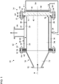
- Fig. 1 schematically shows a configuration of a water treatment device according to the embodiment.
- Fig. 1 schematically shows a configuration of a water treatment device 10 according to the embodiment.
- the water treatment device 10 includes a dual-pipe structure unit 12, a light source unit 14, and an introduction pipe 16.
- the dual-pipe structure unit 12 includes an outer pipe 20 and an inner pipe 30.
- the water treatment device 10 is a device for irradiating water subject to treatment flowing in the inner pipe 30 with ultraviolet light to sterilize the water.
- the longitudinal direction of the outer pipe 20 and the inner pipe 30 may be referred to as "axial direction" to facilitate understanding.
- the direction parallel to the central axis A is the axial direction.
- the direction perpendicular to the axial direction may be referred to as the radial direction, and the direction encircling the axial direction may be referred to as the circumferential direction.
- the outer pipe 20 has a cylindrical shape and extends from a first end 21 to a second end 22 in the axial direction.
- the first end 21 and the second end 22 are provided with a flange that extends radially outward from an outer circumferential surface 23 of the outer pipe 20.
- the outer pipe 20 is made of a resin material or a metallic material.
- the outer pipe 20 is made of stainless steel.
- the axial length of the outer pipe 20 is about 400 mm, and the diameter of an inner circumferential surface 24 of the outer pipe 20 is about 400 mm.
- the outer circumferential surface 23 of the outer pipe 20 is provided with an outflow port 26 and a water intake port 28.
- the outflow port 26 is provided at a position between the first end 221 and the second end 222.
- the water intake port 28 is provided at a position radially opposite to the outflow port 26, sandwiching the inner pipe 30.
- the outflow port 26 is provided on the upper side in the vertical direction, and the water intake port 28 is provided on the lower side in the vertical direction, when the water treatment device 10 is installed for operation. From the perspective of ensuring uniform pressure loss, it is preferred that the outflow port 26 and the water intake port 28 be provided at the center between the first end 21 and the second end 22 or at a position closer to the second end 22 than the center.
- the outflow port 26 and the water intake port 28 may be provided at positions closer to the first end 21 than the second end 22.
- the inner pipe 30 has a cylindrical shape and extends from an opposing end 31 to an inflow end 32 in the axial direction.
- the inner pipe 30 is provided in the outer pipe 20 and is preferably coaxial with the outer pipe 20.
- the inner pipe 30 is made of a material having a high reflectivity and durability for ultraviolet light.
- the inner pipe 30 is made of a fluororesin material such as polytetrafluoroethylene (PTFE).
- PTFE polytetrafluoroethylene
- the axial length of the inner pipe 30 is about 400 mm, and the diameter of the inner circumferential surface 34 of the inner pipe 30 is about 350 mm.
- the inflow end 32 is provided with a flange that extends radially outward from an outer circumferential surface 33 of the inner pipe 30.
- the opposing end 31 is not provided with a flange.
- the opposing end 31 faces a window member 42 of the light source unit 14, sandwiching a gap 76 provided between the opposing end 31 and the window member 42.
- the opposing end 31 and the window member 42 are axially distanced by a dimension defined by the gap 76.
- the gap 76 is provided over the entire circumference of the opposing end 31 and is provided so that the axial distance between the opposing end 31 and the window member 42 (i.e., the dimension of the gap 76) is uniform over the entire circumference. It is preferred that the axial dimension of the gap 76 be not less than 3 mm and not more than 30 mm. In one example, the dimension is about 10 mm.
- the dual-pipe structure unit 12 further includes an inlaid flange 36.
- the inlaid flange 36 is a prevention member provided between the outer pipe 20 and the inner pipe 30 and prevents radial displacement of the inner pipe 30 relative to the outer pipe 20.
- the inlaid flange 36 is provided to block the space between the second end 22 of the outer pipe 20 and the inflow end 32 of the inner pipe 30 and is fixed by being sandwiched between the flange of the second end 22 and the flange of the inflow end 32.
- An O ring is provided between the flange of the second end 22 and the inlaid flange 36.
- the inner pipe 30 and the inlaid flange 36 are formed as separate components.
- the inner pipe 30 and the inlaid flange 36 may be integrated.
- a step in contact with the inner circumferential surface 24 of the outer pipe 20 may be formed at the inflow end 32 of the inner pipe 30.
- the dual-pipe structure unit 12 further includes a lock pin 38.
- the lock pin 38 is a prevention member provided between the outer pipe 20 and the inner pipe 30 and prevents the radial displacement of the inner pipe 30 relative to the outer pipe 20.
- the lock pin 38 is a member radially extending from the inner circumferential surface 24 of the outer pipe 20 toward the outer circumferential surface 33 of the inner pipe 30.
- the lock pin 38 is provided at a plurality of different locations in the circumferential direction.
- the lock pins 38 are provided at equal intervals in the circumferential direction. It is preferred that the lock pin 38 be provided at a position closer to the first end 21 than the second end 22. By proving the lock pin 38 at a position relatively close to the first end 21, the radial displacement of the opposing end 31 of the inner pipe 30 is suitably prevented.
- only one of the inlaid flange 36 and the lock pin 38 may be provided. Still alternatively, neither the inlaid flange 36 nor the lock pin 38 may be provided. In the latter case, a prevention member of a structure different from those of the inlaid flange 36 and the lock pin 38 may be provided.
- the light source unit 14 includes a plurality of light emitting devices 40, a window member 42, and a water-cooled mechanism 50.
- the light source unit 14 is provided at the first end 21 of the outer pipe 20 and is provided to block the opening of the first end 21 in a liquid-tight manner.
- the light source unit 14 radiates ultraviolet light from the opposing end 31 toward the inflow end 32 in the axial direction to irradiate the water subject to treatment flowing in the inner pipe 30.
- the light emitting devices 40 is a so-called ultra violet-light emitting diode (UV-LED) and outputs deep ultraviolet light having a central wavelength or a peak wavelength included in a range of about 200 nm ⁇ 350 nm. It is preferred that the light emitting device 40 emit ultraviolet light near 260 nm ⁇ 290 nm having a high sterilizing efficiency. Such an ultraviolet LED is exemplified by an aluminum gallium nitride (AlGaN) based LED.
- AlGaN aluminum gallium nitride
- a plurality of light emitting devices 40 are attached to the water-cooled mechanism 50. The plurality of light emitting devices 40 are mounted on a plane perpendicular to the axial direction and are arranged in the radial direction and in the circumferential direction within the mounting plane.
- the window member 42 is provided at a position between the opposing end 31 of the inner pipe 30 and the plurality of light emitting devices 40 and are provided to block the opening of the first end 21 of the outer pipe 20.
- the window member 42 is made of a material having a high transmittance for the ultraviolet light from the light emitting devices 40.
- the window member 42 is made of quartz (SiO 2 ).
- the window member 42 has a disc shape. In one embodiment, the diameter of the window member 42 is about 420 mm, and the thickness thereof is about 40 mm.
- a window frame 44 is provided on the outer circumference of the window member 42, and the window member 42 is fixed to the window frame 44. An O ring for liquid-tightness is provided between the window member 42 and the window frame 44.
- the window frame 44 includes an inner window frame 45 and an outer window frame 46.
- the window member 42 is fixed by being sandwiched between the inner window frame 45 and the outer window frame 46.
- the window frame 44 is made of a metallic material such as stainless steel.
- the inner window frame 45 is positioned between the first end 21 and window member 42 and comes into contact with the water subject to treatment flowing in the dual-pipe structure unit 12.
- An O ring is provided between the first end 21 and the inner window frame 45.
- the outer window frame 46 is positioned between the window member 42 and the water-cooled mechanism 50.
- the window frame 44 is fixed to the first end 21 by means of a fastening member 48 comprised of a bolt and nut, or the like.
- the fastening member 48 is guided through a mount hole extending through the flange of the first end 21, the inner window frame 45, and the outer window frame 46 and sandwiches and fixes the first end 21, the inner window frame 45, and the outer window frame 46.
- the water-cooled mechanism 50 uses cooling water supplied from the water intake port 28 to cool the light emitting device 40.
- the water-cooled mechanism 50 includes a cooling water supply port 52 and a cooling water discharge port 54.
- the cooling water supply port 52 is connected to the water intake port 28 via a cooling water supply pipe 56, and a portion of the water subject to treatment flowing in the dual-pipe structure unit 12 is supplied to the cooling water supply port 52 as cooling water.
- the water-cooled mechanism 50 includes a heat sink (not shown) thermally coupled to the light emitting device 40 and an internal pipe (not shown) for circulating cooling water thermally coupled to the heat sink.
- the cooling water flowing through the internal pipe is discharged outside via a cooling water discharge pipe 58 connected to the cooling water discharge port 54.
- the water-cooled mechanism 50 is attached to the outer window frame 46.
- the introduction pipe 16 is a funnel-shaped member and is shaped such that the diameter that grows progressively from an introduction end 61 toward a connection end 62.
- the introduction pipe 16 is made of a metallic material such as stainless steel.
- the introduction end 61 and the connection end 62 are provided with a flange that extends radially outward.
- the connection end 62 is connected to the inflow end 32 of the inner pipe 30.
- the connection end 62 has the same inner diameter as the inner pipe 30 so that the water subject to treatment flows smoothly from the introduction pipe 16 to the inner pipe 30.
- a pipe for supplying water subject to treatment is connected to the introduction end 61.
- the introduction end 61 is configured to have the same inner diameter as the pipe connected thereto.
- the introduction pipe 16 connects between the pipe and the inner pipe 30, which have different diameters, and straightens the flow of the water subject to treatment flowing from the inflow end 32 into the interior of the inner pipe 30.
- the introduction pipe 16 is fixed to the dual-pipe structure unit 12 by means of a fastening member 64.
- the fastening member 64 is guided through a mounting hole extending through the flange of the second end 22, the inlaid flange 36, the flange of the inflow end 32, and the flange of the connection end 62 and sandwiches and fixes these members.
- The allows the inlaid flange 36 to restrict the radial position of the inner pipe 30 and prevents the radial displacement of the inner pipe 30.
- Water subject to treatment is introduced from the introduction end 61 and flows in the axial direction toward the light source unit 14 via an introduction flow passage 72 in the introduction pipe 16 and an internal flow passage 74 in the inner pipe 30.
- the light source unit 14 radiates ultraviolet light in the axial direction to irradiate the water subject to treatment flowing in the internal flow passage 74.
- the water subject to treatment irradiated with ultraviolet light flows out of the inner pipe 30 via the gap 76 between the light source unit 14 and the opposing end 31 and flows out from the outflow port 26 via an external flow passage 78 between the outer pipe 20 and the inner pipe 30.
- a portion of the water subject to treatment is supplied from the water intake port 28 to the water-cooled mechanism 50 via the cooling water supply pipe 56 and is used to cool the plurality of light emitting devices 40.
- the cooling water used is discharged outside from the cooling water discharge port 54.
- the water treatment method using the water treatment device 10 includes irradiating water subject to treatment that flows in from the inflow end 32 and flows in the inner pipe 30 in the axial direction with ultraviolet light and causing the water subject to treatment irradiated with ultraviolet light to flow out from the outflow port 26.
- the water subject to treatment is supplied such that the pressure loss occurring when the water passes through the water treatment device 10 is not less than 5 kPa and not more than 20 kPa.
- the flow of the water subject to treatment in the water treatment device 10 is straightened, and the water subject to treatment as a whole is uniformly irradiated with ultraviolet light.
- the water subject to treatment flowing in the inner pipe 30 is irradiated with ultraviolet light along the flow direction so that the water subject to treatment is affected by ultraviolet light over a period of time in which the water flows in the axial direction.
- ultraviolet light is radiated in a direction perpendicular to the flow direction, the water can be affected by ultraviolet light for only a small period of time in which the water passes in the ultraviolet radiation range.
- it is necessary to secure a long ultraviolet irradiation range by, for example, arranging light sources in the flow direction so as to enhance the action.
- the ultraviolet light from the light source provided at the end of the flow passage is caused to affect the water subject to treatment efficiently.
- the outer circumferential surface 23 and the inner circumferential surface 24 of the inner pipe 30 are prevented from being stained by using a fluororesin such as PTFE as a material of the inner pipe 30.
- PTFE is a material having a high ultraviolet reflectivity so that the ultraviolet light from the light source unit 14 is propagated in the axial direction by reflecting it on the inner circumferential surface 24. This increases the amount of ultraviolet light affecting the water subject to treatment as compared with the case of using a material having a low ultraviolet reflectivity to form the inner pipe 30. Consequently, the water treatment performance is improved.
- the water subject to treatment is caused to flow out of the inner pipe 30 via the gap 76 provided over the entirety of the opposing end 31 so that the flow of the water subject to treatment as a whole is uniformized.
- the flow passage to cause the water to flow out of the inner pipe 30 is provided only in a portion in the circumferential direction or provided asymmetrically in the circumferential direction, the asymmetricity of the flow passage structure induces a disturbance in the flow of the water subject to treatment, which could result in a deviation in the flow rate distribution.
- the action of ultraviolet light is related to the time in which the water subject to treatment flows in the inner pipe 30, i.e., the flow rate.
- the flow rate distribution is uniformized so that the ultraviolet irradiation level is also uniformized. This allows the entirety of the water subject to treatment to be sufficiently sterilized.
- the aforementioned straightening effect is suitably obtained by sizing the gap 76 between the light source unit 14 and the opposing end 31 to be not less than 3 mm and not more than 30 mm.
- the outflow port 26 By providing the outflow port 26 at a position in a range of not less than 10 mm and not more than 100 mm from the first end 21 in the axial direction, the pressure loss in the water treatment device 10 is uniformized.
- the water intake port 28 at a position radially opposite to the outflow port 26, the symmetry of the flow passage structure is enhanced and the pressure loss is conditioned to be even more uniform.
- the displacement of the inner pipe 30 is suitably prevented by providing a prevention member such as the inlaid flange 36 and the lock pin 38.
- a prevention member such as the inlaid flange 36 and the lock pin 38.
- the inner pipe 30 may be vibrated due to the fluid energy from the inflow of the water subject to treatment, and the gap between the outer pipe 20 and the inner pipe 30, i.e., the flow passage width of the external flow passage 78 might vary. Variation in the flow passage width of the external flow passage 78 might result in nonuniform pressure loss and reduction in the treatment performance.
- the prevention member prevents the vibration of the inner pipe 30 and maintains the flow passage width of the external flow passage 78 constant so that the pressure loss is maintained constant.
- 10 ... water treatment device, 12 ... dual-pipe structure unit, 14 ... light source unit, 20 ... outer pipe, 21 ... first end, 22 ... second end, 23 ... outer circumferential surface, 24 ... inner circumferential surface, 26 ... outflow port, 28 ... water intake port, 30 ... inner pipe, 31 ... opposing end, 32 ... inflow end, 33 ... outer circumferential surface, 34 ... inner circumferential surface, 36 ... inlaid flange, 38 ... lock pin, 40 ... light emitting device, 50 ... water-cooled mechanism, 76 ... gap
- the ultraviolet irradiation efficiency is increased and the water treatment performance is improved.
Landscapes
- Health & Medical Sciences (AREA)
- Toxicology (AREA)
- Life Sciences & Earth Sciences (AREA)
- Hydrology & Water Resources (AREA)
- Engineering & Computer Science (AREA)
- Environmental & Geological Engineering (AREA)
- Water Supply & Treatment (AREA)
- Chemical & Material Sciences (AREA)
- Organic Chemistry (AREA)
- Physical Water Treatments (AREA)
Abstract
Description
- The present invention relates to a water treatment device, and, more particularly, a technology of irradiating water subject to treatment with ultraviolet light.
- It is known that ultraviolet light has sterilization capability. Devices that radiate ultraviolet light are used for sterilization in medical and food processing fronts. Devices that sterilize water subject to treatment continuously by irradiating the water subject to treatment with ultraviolet light are also used. One example is a device adapted to radiate ultraviolet light in a direction perpendicular to the direction of flow of the water subject to treatment (see, for example, patent document 1).
[patent document 1]JP2014-233646 - In a configuration in which ultraviolet light is radiated in a direction perpendicular to the direction of flow of the water subject to treatment, it is necessary to arrange light sources along the flow direction in order to apply a sufficient action to the water subject to treatment. It has therefore been impossible to radiate ultraviolet light efficiently.
- In this background, one illustrative purpose of the present invention is to provide a water treatment device in which the efficiency of ultraviolet light irradiation of water subject to treatment is enhanced.
- A water treatment device according to an embodiment of the present invention includes: a dual-pipe structure unit including an outer pipe extending in an axial direction from a first end to a second end, an inner pipe provided in the outer pipe and extending in the axial direction, and a prevention member provided between the outer pipe and the inner pipe and preventing displacement of the inner pipe in a radial direction relative to the outer pipe; and a light source unit provided to block an opening of the first end of the outer pipe in a liquid-tight manner and radiating ultraviolet light in the axial direction to irradiate water subject to treatment flowing in the inner pipe. The inner pipe includes an opposing end facing the light source unit across a gap provided between the opposing end and the light source unit, and an inflow end positioned opposite to the opposing end, the water subject to treatment flowing in through the inflow end. The outer pipe includes an outflow port provided on an outer circumferential surface of the outer pipe, and the water subject to treatment flowing out of the inner pipe via the gap flows out from the outflow port.
- According to the embodiment, the water subject to treatment is irradiated with ultraviolet light along the flow direction in the inner pipe so that the water subject to treatment is affected by ultraviolet light over a period of time in which the water flows in the direction of ultraviolet irradiation. In this way, ultraviolet light is radiated more efficiently than in the case of radiating ultraviolet light in a direction perpendicular to the direction of flow of the water subject to treatment. Further, by configuring the flow passage to have a dual-pipe structure to cause the water subject to treatment to flow out of the inner pipe via the gap between the inner pipe and the light source unit, the flow of the water subject to treatment in the inner pipe is straightened. This ensures that the water subject to treatment as a whole is uniformly affected by ultraviolet light and enhances the effect of water treatment. Further, by providing the prevention member that prevents the radial displacement of the inner pipe relative to the outer pipe, the flow passage width between the outer pipe and the inner pipe is maintained constant, and the flow of the water subject to treatment is straightened, even when the dual-pipe structure elongated in the axial direction is employed.
- The prevention member may include an inlaid flange provided to block a space between the second end of the outer pipe and the inflow end of the inner pipe.
- The prevention member may include a lock pin extending in a radial direction from an inner circumferential surface of the outer pipe toward an outer circumferential surface of the inner pipe at a position closer to the first end than the second end.
- A dimension of the gap in the axial direction may be not less than 3 mm and not more than 30 mm.
- A difference between an inner diameter of the outer pipe and an outer diameter of the inner pipe may be not less than 10 mm and not more than 50 mm.
- The outflow port may be provided at a position closer to the second end than the first end.
- The light source unit may include a light emitting device for emitting ultraviolet light and a water-cooled mechanism for cooling the light emitting device, and the water-cooled mechanism may be configured to be supplied with cooling water from a water intake port provided on the outer circumferential surface of the outer pipe, and the water intake port may be provided at a position radially opposite to the outflow port, sandwiching the inner pipe.
- Another embodiment of the present invention relates to a water treatment method that uses the water treatment device. The method includes: irradiating the water subject to treatment flowing in from the inflow end and flowing in the inner pipe in the axial direction with ultraviolet light and causing the water subject to treatment irradiated with ultraviolet light to flow out from the outflow port, wherein the water subject to treatment is supplied such that a pressure loss occurring when the water passes through the water treatment device is not less than 5 kPa and not more than 20 kPa.
- According to the embodiment, the flow of the water subject to treatment in the inner pipe is straightened by ensuing that the pressure loss is not less than 5 kPa and not more than 20 kPa. This ensures that the water subject to treatment as a whole is uniformly affected by ultraviolet light and enhances the effect of water treatment.
- According to the present invention, the efficiency of ultraviolet irradiation is enhanced, and the water treatment performance is improved.
-
Fig. 1 schematically shows a configuration of a water treatment device according to the embodiment. - A detailed description will be given of embodiments of the present invention with reference to the drawings. Like numerals are used in the description to denote like elements and a duplicate description is omitted as appropriate.
-
Fig. 1 schematically shows a configuration of awater treatment device 10 according to the embodiment. Thewater treatment device 10 includes a dual-pipe structure unit 12, alight source unit 14, and anintroduction pipe 16. The dual-pipe structure unit 12 includes anouter pipe 20 and aninner pipe 30. Thewater treatment device 10 is a device for irradiating water subject to treatment flowing in theinner pipe 30 with ultraviolet light to sterilize the water. - In this specification, the longitudinal direction of the
outer pipe 20 and theinner pipe 30 may be referred to as "axial direction" to facilitate understanding. For example, referring toFig. 1 , the direction parallel to the central axis A is the axial direction. The direction perpendicular to the axial direction may be referred to as the radial direction, and the direction encircling the axial direction may be referred to as the circumferential direction. - The
outer pipe 20 has a cylindrical shape and extends from afirst end 21 to asecond end 22 in the axial direction. Thefirst end 21 and thesecond end 22 are provided with a flange that extends radially outward from an outercircumferential surface 23 of theouter pipe 20. Theouter pipe 20 is made of a resin material or a metallic material. For example, theouter pipe 20 is made of stainless steel. In one example, the axial length of theouter pipe 20 is about 400 mm, and the diameter of an innercircumferential surface 24 of theouter pipe 20 is about 400 mm. - The outer
circumferential surface 23 of theouter pipe 20 is provided with anoutflow port 26 and awater intake port 28. Theoutflow port 26 is provided at a position between the first end 221 and the second end 222. Thewater intake port 28 is provided at a position radially opposite to theoutflow port 26, sandwiching theinner pipe 30. For example, theoutflow port 26 is provided on the upper side in the vertical direction, and thewater intake port 28 is provided on the lower side in the vertical direction, when thewater treatment device 10 is installed for operation. From the perspective of ensuring uniform pressure loss, it is preferred that theoutflow port 26 and thewater intake port 28 be provided at the center between thefirst end 21 and thesecond end 22 or at a position closer to thesecond end 22 than the center. In the case of a flow passage structure in which the uniformity of pressure loss is not affected much if the positions of theoutflow port 26 and thewater intake port 28 are changed, theoutflow port 26 and thewater intake port 28 may be provided at positions closer to thefirst end 21 than thesecond end 22. - The
inner pipe 30 has a cylindrical shape and extends from anopposing end 31 to aninflow end 32 in the axial direction. Theinner pipe 30 is provided in theouter pipe 20 and is preferably coaxial with theouter pipe 20. Theinner pipe 30 is made of a material having a high reflectivity and durability for ultraviolet light. For example, theinner pipe 30 is made of a fluororesin material such as polytetrafluoroethylene (PTFE). In one example, the axial length of theinner pipe 30 is about 400 mm, and the diameter of the innercircumferential surface 34 of theinner pipe 30 is about 350 mm. - The
inflow end 32 is provided with a flange that extends radially outward from an outercircumferential surface 33 of theinner pipe 30. On the other hand, theopposing end 31 is not provided with a flange. Theopposing end 31 faces awindow member 42 of thelight source unit 14, sandwiching agap 76 provided between theopposing end 31 and thewindow member 42. In other words, theopposing end 31 and thewindow member 42 are axially distanced by a dimension defined by thegap 76. Thegap 76 is provided over the entire circumference of the opposingend 31 and is provided so that the axial distance between the opposingend 31 and the window member 42 (i.e., the dimension of the gap 76) is uniform over the entire circumference. It is preferred that the axial dimension of thegap 76 be not less than 3 mm and not more than 30 mm. In one example, the dimension is about 10 mm. - The dual-
pipe structure unit 12 further includes an inlaidflange 36. The inlaidflange 36 is a prevention member provided between theouter pipe 20 and theinner pipe 30 and prevents radial displacement of theinner pipe 30 relative to theouter pipe 20. The inlaidflange 36 is provided to block the space between thesecond end 22 of theouter pipe 20 and theinflow end 32 of theinner pipe 30 and is fixed by being sandwiched between the flange of thesecond end 22 and the flange of theinflow end 32. An O ring is provided between the flange of thesecond end 22 and the inlaidflange 36. In the illustrated example, theinner pipe 30 and the inlaidflange 36 are formed as separate components. In one variation, theinner pipe 30 and the inlaidflange 36 may be integrated. For example, a step in contact with the innercircumferential surface 24 of theouter pipe 20 may be formed at theinflow end 32 of theinner pipe 30. - The dual-
pipe structure unit 12 further includes alock pin 38. Thelock pin 38 is a prevention member provided between theouter pipe 20 and theinner pipe 30 and prevents the radial displacement of theinner pipe 30 relative to theouter pipe 20. Thelock pin 38 is a member radially extending from the innercircumferential surface 24 of theouter pipe 20 toward the outercircumferential surface 33 of theinner pipe 30. Thelock pin 38 is provided at a plurality of different locations in the circumferential direction. For example, the lock pins 38 are provided at equal intervals in the circumferential direction. It is preferred that thelock pin 38 be provided at a position closer to thefirst end 21 than thesecond end 22. By proving thelock pin 38 at a position relatively close to thefirst end 21, the radial displacement of the opposingend 31 of theinner pipe 30 is suitably prevented. - In one variation, only one of the inlaid
flange 36 and thelock pin 38 may be provided. Still alternatively, neither the inlaidflange 36 nor thelock pin 38 may be provided. In the latter case, a prevention member of a structure different from those of the inlaidflange 36 and thelock pin 38 may be provided. - The
light source unit 14 includes a plurality of light emittingdevices 40, awindow member 42, and a water-cooledmechanism 50. Thelight source unit 14 is provided at thefirst end 21 of theouter pipe 20 and is provided to block the opening of thefirst end 21 in a liquid-tight manner. Thelight source unit 14 radiates ultraviolet light from the opposingend 31 toward theinflow end 32 in the axial direction to irradiate the water subject to treatment flowing in theinner pipe 30. - The
light emitting devices 40 is a so-called ultra violet-light emitting diode (UV-LED) and outputs deep ultraviolet light having a central wavelength or a peak wavelength included in a range of about 200 nm ∼ 350 nm. It is preferred that thelight emitting device 40 emit ultraviolet light near 260 nm ∼ 290 nm having a high sterilizing efficiency. Such an ultraviolet LED is exemplified by an aluminum gallium nitride (AlGaN) based LED. A plurality of light emittingdevices 40 are attached to the water-cooledmechanism 50. The plurality of light emittingdevices 40 are mounted on a plane perpendicular to the axial direction and are arranged in the radial direction and in the circumferential direction within the mounting plane. - The
window member 42 is provided at a position between the opposingend 31 of theinner pipe 30 and the plurality of light emittingdevices 40 and are provided to block the opening of thefirst end 21 of theouter pipe 20. Thewindow member 42 is made of a material having a high transmittance for the ultraviolet light from thelight emitting devices 40. For example, thewindow member 42 is made of quartz (SiO2). Thewindow member 42 has a disc shape. In one embodiment, the diameter of thewindow member 42 is about 420 mm, and the thickness thereof is about 40 mm. Awindow frame 44 is provided on the outer circumference of thewindow member 42, and thewindow member 42 is fixed to thewindow frame 44. An O ring for liquid-tightness is provided between thewindow member 42 and thewindow frame 44. - The
window frame 44 includes aninner window frame 45 and anouter window frame 46. Thewindow member 42 is fixed by being sandwiched between theinner window frame 45 and theouter window frame 46. Thewindow frame 44 is made of a metallic material such as stainless steel. Theinner window frame 45 is positioned between thefirst end 21 andwindow member 42 and comes into contact with the water subject to treatment flowing in the dual-pipe structure unit 12. An O ring is provided between thefirst end 21 and theinner window frame 45. Theouter window frame 46 is positioned between thewindow member 42 and the water-cooledmechanism 50. Thewindow frame 44 is fixed to thefirst end 21 by means of afastening member 48 comprised of a bolt and nut, or the like. Thefastening member 48 is guided through a mount hole extending through the flange of thefirst end 21, theinner window frame 45, and theouter window frame 46 and sandwiches and fixes thefirst end 21, theinner window frame 45, and theouter window frame 46. - The water-cooled
mechanism 50 uses cooling water supplied from thewater intake port 28 to cool the light emittingdevice 40. The water-cooledmechanism 50 includes a coolingwater supply port 52 and a coolingwater discharge port 54. The coolingwater supply port 52 is connected to thewater intake port 28 via a coolingwater supply pipe 56, and a portion of the water subject to treatment flowing in the dual-pipe structure unit 12 is supplied to the coolingwater supply port 52 as cooling water. The water-cooledmechanism 50 includes a heat sink (not shown) thermally coupled to thelight emitting device 40 and an internal pipe (not shown) for circulating cooling water thermally coupled to the heat sink. The cooling water flowing through the internal pipe is discharged outside via a cooling water discharge pipe 58 connected to the coolingwater discharge port 54. The water-cooledmechanism 50 is attached to theouter window frame 46. - The
introduction pipe 16 is a funnel-shaped member and is shaped such that the diameter that grows progressively from anintroduction end 61 toward aconnection end 62. Theintroduction pipe 16 is made of a metallic material such as stainless steel. Theintroduction end 61 and theconnection end 62 are provided with a flange that extends radially outward. Theconnection end 62 is connected to theinflow end 32 of theinner pipe 30. Theconnection end 62 has the same inner diameter as theinner pipe 30 so that the water subject to treatment flows smoothly from theintroduction pipe 16 to theinner pipe 30. A pipe for supplying water subject to treatment is connected to theintroduction end 61. Theintroduction end 61 is configured to have the same inner diameter as the pipe connected thereto. Theintroduction pipe 16 connects between the pipe and theinner pipe 30, which have different diameters, and straightens the flow of the water subject to treatment flowing from theinflow end 32 into the interior of theinner pipe 30. - The
introduction pipe 16 is fixed to the dual-pipe structure unit 12 by means of afastening member 64. Thefastening member 64 is guided through a mounting hole extending through the flange of thesecond end 22, the inlaidflange 36, the flange of theinflow end 32, and the flange of theconnection end 62 and sandwiches and fixes these members. The allows the inlaidflange 36 to restrict the radial position of theinner pipe 30 and prevents the radial displacement of theinner pipe 30. - A description will now be given of the operation of the
water treatment device 10 having the above configuration. Water subject to treatment is introduced from theintroduction end 61 and flows in the axial direction toward thelight source unit 14 via anintroduction flow passage 72 in theintroduction pipe 16 and aninternal flow passage 74 in theinner pipe 30. Thelight source unit 14 radiates ultraviolet light in the axial direction to irradiate the water subject to treatment flowing in theinternal flow passage 74. The water subject to treatment irradiated with ultraviolet light flows out of theinner pipe 30 via thegap 76 between thelight source unit 14 and the opposingend 31 and flows out from theoutflow port 26 via anexternal flow passage 78 between theouter pipe 20 and theinner pipe 30. A portion of the water subject to treatment is supplied from thewater intake port 28 to the water-cooledmechanism 50 via the coolingwater supply pipe 56 and is used to cool the plurality of light emittingdevices 40. The cooling water used is discharged outside from the coolingwater discharge port 54. - The water treatment method using the
water treatment device 10 includes irradiating water subject to treatment that flows in from theinflow end 32 and flows in theinner pipe 30 in the axial direction with ultraviolet light and causing the water subject to treatment irradiated with ultraviolet light to flow out from theoutflow port 26. In this process, the water subject to treatment is supplied such that the pressure loss occurring when the water passes through thewater treatment device 10 is not less than 5 kPa and not more than 20 kPa. By supplying water subject to treatment such that the pressure loss is within such a range, the flow of the water subject to treatment in thewater treatment device 10 is straightened, and the water subject to treatment as a whole is uniformly irradiated with ultraviolet light. - A description will be given of the advantage achieved by the embodiment. According to the embodiment, the water subject to treatment flowing in the
inner pipe 30 is irradiated with ultraviolet light along the flow direction so that the water subject to treatment is affected by ultraviolet light over a period of time in which the water flows in the axial direction. Provided that ultraviolet light is radiated in a direction perpendicular to the flow direction, the water can be affected by ultraviolet light for only a small period of time in which the water passes in the ultraviolet radiation range. In this case, it is necessary to secure a long ultraviolet irradiation range by, for example, arranging light sources in the flow direction so as to enhance the action. Meanwhile, it is ensured that the action takes place over a long distance merely by providing thelight source unit 14 at a position facing the flow direction. Thus, according to the embodiment, the ultraviolet light from the light source provided at the end of the flow passage is caused to affect the water subject to treatment efficiently. - According to the embodiment, the outer
circumferential surface 23 and the innercircumferential surface 24 of theinner pipe 30 are prevented from being stained by using a fluororesin such as PTFE as a material of theinner pipe 30. Further, PTFE is a material having a high ultraviolet reflectivity so that the ultraviolet light from thelight source unit 14 is propagated in the axial direction by reflecting it on the innercircumferential surface 24. This increases the amount of ultraviolet light affecting the water subject to treatment as compared with the case of using a material having a low ultraviolet reflectivity to form theinner pipe 30. Consequently, the water treatment performance is improved. - According to the embodiment, the water subject to treatment is caused to flow out of the
inner pipe 30 via thegap 76 provided over the entirety of the opposingend 31 so that the flow of the water subject to treatment as a whole is uniformized. Provided that the flow passage to cause the water to flow out of theinner pipe 30 is provided only in a portion in the circumferential direction or provided asymmetrically in the circumferential direction, the asymmetricity of the flow passage structure induces a disturbance in the flow of the water subject to treatment, which could result in a deviation in the flow rate distribution. The action of ultraviolet light is related to the time in which the water subject to treatment flows in theinner pipe 30, i.e., the flow rate. Therefore, a deviation created in the flow passage distribution results in a localized shortage of the irradiation level. According to the embodiment, the flow rate distribution is uniformized so that the ultraviolet irradiation level is also uniformized. This allows the entirety of the water subject to treatment to be sufficiently sterilized. - According to the embodiment, the aforementioned straightening effect is suitably obtained by sizing the
gap 76 between thelight source unit 14 and the opposingend 31 to be not less than 3 mm and not more than 30 mm. By providing theoutflow port 26 at a position in a range of not less than 10 mm and not more than 100 mm from thefirst end 21 in the axial direction, the pressure loss in thewater treatment device 10 is uniformized. Similarly, by providing thewater intake port 28 at a position radially opposite to theoutflow port 26, the symmetry of the flow passage structure is enhanced and the pressure loss is conditioned to be even more uniform. - According to the embodiment, the displacement of the
inner pipe 30 is suitably prevented by providing a prevention member such as the inlaidflange 36 and thelock pin 38. If the volume of flow of the water subject to treatment is large, theinner pipe 30 may be vibrated due to the fluid energy from the inflow of the water subject to treatment, and the gap between theouter pipe 20 and theinner pipe 30, i.e., the flow passage width of theexternal flow passage 78 might vary. Variation in the flow passage width of theexternal flow passage 78 might result in nonuniform pressure loss and reduction in the treatment performance. According to the embodiment, the prevention member prevents the vibration of theinner pipe 30 and maintains the flow passage width of theexternal flow passage 78 constant so that the pressure loss is maintained constant. - Described above is an explanation based on an exemplary embodiment. The embodiment is intended to be illustrative only and it will be understood by those skilled in the art that various design changes are possible and various modifications are possible and that such modifications are also within the scope of the present invention.
- 10 ... water treatment device, 12 ... dual-pipe structure unit, 14 ... light source unit, 20 ... outer pipe, 21 ... first end, 22 ... second end, 23 ... outer circumferential surface, 24 ... inner circumferential surface, 26 ... outflow port, 28 ... water intake port, 30 ... inner pipe, 31 ... opposing end, 32 ... inflow end, 33 ... outer circumferential surface, 34 ... inner circumferential surface, 36 ... inlaid flange, 38 ... lock pin, 40 ... light emitting device, 50 ... water-cooled mechanism, 76 ... gap
- According to the present invention, the ultraviolet irradiation efficiency is increased and the water treatment performance is improved.
Claims (8)
- A water treatment device comprising:a dual-pipe structure unit including an outer pipe extending in an axial direction from a first end to a second end, an inner pipe provided in the outer pipe and extending in the axial direction, and a prevention member provided between the outer pipe and the inner pipe and preventing displacement of the inner pipe in a radial direction relative to the outer pipe; anda light source unit provided to block an opening of the first end of the outer pipe in a liquid-tight manner and radiating ultraviolet light in the axial direction to irradiate water subject to treatment flowing in the inner pipe, whereinthe inner pipe includes an opposing end facing the light source unit across a gap provided between the opposing end and the light source unit, and an inflow end positioned opposite to the opposing end, the water subject to treatment flowing in through the inflow end, andthe outer pipe includes an outflow port provided on an outer circumferential surface of the outer pipe, and the water subject to treatment flowing out of the inner pipe via the gap flows out from the outflow port.
- The water treatment device according to claim 1, wherein
the prevention member includes an inlaid flange provided to block a space between the second end of the outer pipe and the inflow end of the inner pipe. - The water treatment device according to claim 1 or 2, wherein
the prevention member includes a lock pin extending in a radial direction from an inner circumferential surface of the outer pipe toward an outer circumferential surface of the inner pipe at a position closer to the first end than the second end. - The water treatment device according to any one of claims 1 through 3, wherein
a dimension of the gap in the axial direction is not less than 3 mm and not more than 30 mm. - The water treatment device according to any one of claims 1 through 4, wherein
a difference between an inner diameter of the outer pipe and an outer diameter of the inner pipe is not less than 10 mm and not more than 50 mm. - The water treatment device according to any one of claims 1 through 5, wherein
the outflow port is provided at a position closer to the second end than the first end. - The water treatment device according to any one of claims 1 through 6, wherein
the light source unit includes a light emitting device for emitting ultraviolet light and a water-cooled mechanism for cooling the light emitting device, and the water-cooled mechanism is configured to be supplied with cooling water from a water intake port provided on the outer circumferential surface of the outer pipe, and
the water intake port is provided at a position radially opposite to the outflow port, sandwiching the inner pipe. - A water treatment method that uses the water treatment device according to any one of claims 1 through 7, comprising:irradiating the water subject to treatment flowing in from the inflow end and flowing in the inner pipe in the axial direction with ultraviolet light and causing the water subject to treatment irradiated with ultraviolet light to flow out from the outflow port, whereinthe water subject to treatment is supplied such that a pressure loss occurring when the water passes through the water treatment device is not less than 5 kPa and not more than 20 kPa.
Applications Claiming Priority (2)
| Application Number | Priority Date | Filing Date | Title |
|---|---|---|---|
| JP2016212761A JP6681314B2 (en) | 2016-10-31 | 2016-10-31 | Water treatment apparatus and water treatment method |
| PCT/JP2017/036922 WO2018079274A1 (en) | 2016-10-31 | 2017-10-12 | Water treatment device and water treatment method |
Publications (3)
| Publication Number | Publication Date |
|---|---|
| EP3533767A1 true EP3533767A1 (en) | 2019-09-04 |
| EP3533767A4 EP3533767A4 (en) | 2020-04-08 |
| EP3533767B1 EP3533767B1 (en) | 2022-04-06 |
Family
ID=62023532
Family Applications (1)
| Application Number | Title | Priority Date | Filing Date |
|---|---|---|---|
| EP17865086.7A Active EP3533767B1 (en) | 2016-10-31 | 2017-10-12 | Water treatment device |
Country Status (8)
| Country | Link |
|---|---|
| US (1) | US10669167B2 (en) |
| EP (1) | EP3533767B1 (en) |
| JP (1) | JP6681314B2 (en) |
| CN (1) | CN110049951A (en) |
| CA (1) | CA3042157C (en) |
| SG (1) | SG11201903813WA (en) |
| TW (1) | TWI717565B (en) |
| WO (1) | WO2018079274A1 (en) |
Families Citing this family (15)
| Publication number | Priority date | Publication date | Assignee | Title |
|---|---|---|---|---|
| JP6891537B2 (en) * | 2017-02-28 | 2021-06-18 | 東芝ライテック株式会社 | Fluid sterilizer |
| JP6909175B2 (en) * | 2018-04-20 | 2021-07-28 | 旭化成株式会社 | Fluid sterilization module |
| JP6994687B2 (en) * | 2018-08-08 | 2022-01-14 | 株式会社Uskテクノロジー | Fluid sterilizer |
| JP7267699B2 (en) * | 2018-09-07 | 2023-05-02 | スタンレー電気株式会社 | Fluid sterilizer |
| JP7230624B2 (en) | 2019-03-25 | 2023-03-01 | 東芝ライテック株式会社 | Fluid sterilizer |
| US12161768B2 (en) | 2019-07-31 | 2024-12-10 | Asahi Kasei Kabushiki Kaisha | Ultraviolet irradiation apparatus and ultraviolet irradiation method |
| US11365134B2 (en) | 2019-07-31 | 2022-06-21 | Access Business Group International Llc | Water treatment system |
| CN110921766B (en) * | 2019-09-11 | 2023-01-13 | 上海紫奕光电科技有限公司 | Fluid disinfection equipment |
| JP7370261B2 (en) * | 2020-01-28 | 2023-10-27 | スタンレー電気株式会社 | Fluid sterilizer and fluid sterilizer unit |
| JP7445191B2 (en) * | 2020-03-16 | 2024-03-07 | 東芝ライテック株式会社 | Fluid sterilizer and fluid sterilization system |
| JP7512799B2 (en) | 2020-09-28 | 2024-07-09 | 東芝ライテック株式会社 | Fluid Sterilization Device |
| JP7632120B2 (en) * | 2020-10-29 | 2025-02-19 | 東芝ライテック株式会社 | Fluid Sterilization Device |
| DE202022000913U1 (en) | 2022-04-11 | 2023-07-14 | PURION GmbH | UV water treatment unit |
| JP2024014411A (en) * | 2022-07-22 | 2024-02-01 | スタンレー電気株式会社 | fluid sterilizer |
| JP2025054392A (en) | 2023-09-26 | 2025-04-08 | 東芝ライテック株式会社 | Fluid Sterilization Device |
Family Cites Families (15)
| Publication number | Priority date | Publication date | Assignee | Title |
|---|---|---|---|---|
| JPS53539A (en) * | 1976-06-23 | 1978-01-06 | Nissan Motor Co Ltd | Driving wheel of vehicle for rope transit system |
| JP2003109186A (en) * | 2001-09-27 | 2003-04-11 | Shinohara Electric Co Ltd | Supporting device for signal |
| US7169311B2 (en) * | 2001-10-17 | 2007-01-30 | Honeywell International, Inc. | Apparatus for disinfecting water using ultraviolet radiation |
| IL157229A (en) * | 2003-08-04 | 2006-08-20 | Zamir Tribelsky | Method for energy coupling especially useful for disinfecting and various systems using it |
| US7544291B2 (en) * | 2004-12-21 | 2009-06-09 | Ranco Incorporated Of Delaware | Water purification system utilizing a plurality of ultraviolet light emitting diodes |
| ATE454359T1 (en) * | 2006-11-06 | 2010-01-15 | Sev Trent Water Purification I | DEVICE FOR WATER DISINFECTION |
| CN200980846Y (en) * | 2006-11-24 | 2007-11-28 | 冼国佳 | Sterilizing device |
| JP5674436B2 (en) * | 2010-11-29 | 2015-02-25 | 前澤工業株式会社 | UV irradiation water treatment equipment |
| EP3461793B1 (en) * | 2013-01-24 | 2022-03-02 | Atlantium Technologies Ltd. | Method and apparatus for liquid disinfection by light emitted from light emitting diodes |
| EP2967057B1 (en) * | 2013-03-15 | 2018-11-21 | Dow AgroSciences LLC | Novel 4-aminopyridine and 6-aminopyrimidine carboxylates as herbicides |
| US20140263090A1 (en) * | 2013-03-15 | 2014-09-18 | Stephen A. Yencho | High Flow Rate Fluid Disinfection System |
| EP2999669B1 (en) * | 2013-05-22 | 2017-02-08 | Merck Patent GmbH | Apparatus for the disinfection of fluids by ultraviolet radiation |
| JP2014233646A (en) | 2013-05-30 | 2014-12-15 | 日機装株式会社 | Water purifier |
| CN110422906A (en) * | 2013-09-05 | 2019-11-08 | 首尔伟傲世有限公司 | Sterilizing unit |
| KR101379737B1 (en) * | 2013-09-06 | 2014-04-01 | 피엠라이트 주식회사 | Uv sterilization lamp and system for waste water disposal |
-
2016
- 2016-10-31 JP JP2016212761A patent/JP6681314B2/en active Active
-
2017
- 2017-10-12 WO PCT/JP2017/036922 patent/WO2018079274A1/en not_active Ceased
- 2017-10-12 EP EP17865086.7A patent/EP3533767B1/en active Active
- 2017-10-12 CA CA3042157A patent/CA3042157C/en active Active
- 2017-10-12 CN CN201780067837.XA patent/CN110049951A/en active Pending
- 2017-10-12 SG SG11201903813WA patent/SG11201903813WA/en unknown
- 2017-10-25 TW TW106136716A patent/TWI717565B/en active
-
2019
- 2019-04-30 US US16/399,070 patent/US10669167B2/en active Active
Also Published As
| Publication number | Publication date |
|---|---|
| EP3533767B1 (en) | 2022-04-06 |
| CA3042157C (en) | 2021-03-30 |
| TWI717565B (en) | 2021-02-01 |
| CA3042157A1 (en) | 2018-05-03 |
| US20190256380A1 (en) | 2019-08-22 |
| EP3533767A4 (en) | 2020-04-08 |
| US10669167B2 (en) | 2020-06-02 |
| JP2018069166A (en) | 2018-05-10 |
| CN110049951A (en) | 2019-07-23 |
| WO2018079274A1 (en) | 2018-05-03 |
| JP6681314B2 (en) | 2020-04-15 |
| TW201819315A (en) | 2018-06-01 |
| SG11201903813WA (en) | 2019-05-30 |
Similar Documents
| Publication | Publication Date | Title |
|---|---|---|
| US10669167B2 (en) | Water treatment device and water treatment method | |
| US10472260B2 (en) | Fluid sterilization device | |
| US11396458B2 (en) | Fluid sterilization apparatus | |
| US9999696B2 (en) | Compact system with high homogeneity of the radiation field | |
| CN208087261U (en) | Fluid sterilizing unit | |
| US20180155215A1 (en) | Sterilization device | |
| EP3508454B1 (en) | Ultraviolet sterilization device | |
| JP6189914B2 (en) | Ultraviolet irradiation module cell, ultraviolet irradiation module, and installation method of ultraviolet irradiation module | |
| US20180244543A1 (en) | Fluid sterilization device | |
| JP7270371B2 (en) | Fluid sterilizer | |
| EP3363468A1 (en) | Fluid sterilization device and fluid sterilization method | |
| TW201802036A (en) | Fluid sterilization device capable of effectively obtaining a sterilizing effect | |
| CN105164056B (en) | The method and apparatus for carrying out liquid disinfection for the light by launching from light emitting diode | |
| WO2021085143A1 (en) | Fluid sterilization device | |
| CN111001019A (en) | Device and apparatus for disinfecting a fluid | |
| EP4529931A1 (en) | Fluid sterilization device | |
| JP2022038707A (en) | Liquid sterilizer | |
| JP2013013871A (en) | Ultraviolet irradiation apparatus | |
| EP4420686A1 (en) | Fluid sterilization device | |
| CN105358246A (en) | Apparatus for thermal treatment of an inner surface of a tubular or other enclosed structure | |
| JP7275671B2 (en) | Fluid sterilizer | |
| TW202244008A (en) | Water treatment device with internal chamber | |
| RU2573723C1 (en) | Ultrasonic emulsifier |
Legal Events
| Date | Code | Title | Description |
|---|---|---|---|
| STAA | Information on the status of an ep patent application or granted ep patent |
Free format text: STATUS: THE INTERNATIONAL PUBLICATION HAS BEEN MADE |
|
| PUAI | Public reference made under article 153(3) epc to a published international application that has entered the european phase |
Free format text: ORIGINAL CODE: 0009012 |
|
| STAA | Information on the status of an ep patent application or granted ep patent |
Free format text: STATUS: REQUEST FOR EXAMINATION WAS MADE |
|
| 17P | Request for examination filed |
Effective date: 20190523 |
|
| AK | Designated contracting states |
Kind code of ref document: A1 Designated state(s): AL AT BE BG CH CY CZ DE DK EE ES FI FR GB GR HR HU IE IS IT LI LT LU LV MC MK MT NL NO PL PT RO RS SE SI SK SM TR |
|
| AX | Request for extension of the european patent |
Extension state: BA ME |
|
| DAV | Request for validation of the european patent (deleted) | ||
| DAX | Request for extension of the european patent (deleted) | ||
| A4 | Supplementary search report drawn up and despatched |
Effective date: 20200306 |
|
| RIC1 | Information provided on ipc code assigned before grant |
Ipc: C02F 1/32 20060101AFI20200302BHEP |
|
| STAA | Information on the status of an ep patent application or granted ep patent |
Free format text: STATUS: EXAMINATION IS IN PROGRESS |
|
| 17Q | First examination report despatched |
Effective date: 20201007 |
|
| GRAP | Despatch of communication of intention to grant a patent |
Free format text: ORIGINAL CODE: EPIDOSNIGR1 |
|
| STAA | Information on the status of an ep patent application or granted ep patent |
Free format text: STATUS: GRANT OF PATENT IS INTENDED |
|
| INTG | Intention to grant announced |
Effective date: 20211102 |
|
| GRAS | Grant fee paid |
Free format text: ORIGINAL CODE: EPIDOSNIGR3 |
|
| GRAA | (expected) grant |
Free format text: ORIGINAL CODE: 0009210 |
|
| STAA | Information on the status of an ep patent application or granted ep patent |
Free format text: STATUS: THE PATENT HAS BEEN GRANTED |
|
| RAP3 | Party data changed (applicant data changed or rights of an application transferred) |
Owner name: SENKO RIKEN CO., LTD. Owner name: METAWATER CO., LTD. Owner name: NIKKISO CO., LTD. |
|
| AK | Designated contracting states |
Kind code of ref document: B1 Designated state(s): AL AT BE BG CH CY CZ DE DK EE ES FI FR GB GR HR HU IE IS IT LI LT LU LV MC MK MT NL NO PL PT RO RS SE SI SK SM TR |
|
| REG | Reference to a national code |
Ref country code: GB Ref legal event code: FG4D |
|
| REG | Reference to a national code |
Ref country code: CH Ref legal event code: EP |
|
| REG | Reference to a national code |
Ref country code: AT Ref legal event code: REF Ref document number: 1481202 Country of ref document: AT Kind code of ref document: T Effective date: 20220415 |
|
| REG | Reference to a national code |
Ref country code: IE Ref legal event code: FG4D |
|
| REG | Reference to a national code |
Ref country code: DE Ref legal event code: R096 Ref document number: 602017055730 Country of ref document: DE |
|
| REG | Reference to a national code |
Ref country code: NL Ref legal event code: FP |
|
| REG | Reference to a national code |
Ref country code: NO Ref legal event code: T2 Effective date: 20220406 |
|
| REG | Reference to a national code |
Ref country code: LT Ref legal event code: MG9D |
|
| REG | Reference to a national code |
Ref country code: AT Ref legal event code: MK05 Ref document number: 1481202 Country of ref document: AT Kind code of ref document: T Effective date: 20220406 |
|
| PG25 | Lapsed in a contracting state [announced via postgrant information from national office to epo] |
Ref country code: SE Free format text: LAPSE BECAUSE OF FAILURE TO SUBMIT A TRANSLATION OF THE DESCRIPTION OR TO PAY THE FEE WITHIN THE PRESCRIBED TIME-LIMIT Effective date: 20220406 Ref country code: PT Free format text: LAPSE BECAUSE OF FAILURE TO SUBMIT A TRANSLATION OF THE DESCRIPTION OR TO PAY THE FEE WITHIN THE PRESCRIBED TIME-LIMIT Effective date: 20220808 Ref country code: LT Free format text: LAPSE BECAUSE OF FAILURE TO SUBMIT A TRANSLATION OF THE DESCRIPTION OR TO PAY THE FEE WITHIN THE PRESCRIBED TIME-LIMIT Effective date: 20220406 Ref country code: HR Free format text: LAPSE BECAUSE OF FAILURE TO SUBMIT A TRANSLATION OF THE DESCRIPTION OR TO PAY THE FEE WITHIN THE PRESCRIBED TIME-LIMIT Effective date: 20220406 Ref country code: GR Free format text: LAPSE BECAUSE OF FAILURE TO SUBMIT A TRANSLATION OF THE DESCRIPTION OR TO PAY THE FEE WITHIN THE PRESCRIBED TIME-LIMIT Effective date: 20220707 Ref country code: FI Free format text: LAPSE BECAUSE OF FAILURE TO SUBMIT A TRANSLATION OF THE DESCRIPTION OR TO PAY THE FEE WITHIN THE PRESCRIBED TIME-LIMIT Effective date: 20220406 Ref country code: ES Free format text: LAPSE BECAUSE OF FAILURE TO SUBMIT A TRANSLATION OF THE DESCRIPTION OR TO PAY THE FEE WITHIN THE PRESCRIBED TIME-LIMIT Effective date: 20220406 Ref country code: BG Free format text: LAPSE BECAUSE OF FAILURE TO SUBMIT A TRANSLATION OF THE DESCRIPTION OR TO PAY THE FEE WITHIN THE PRESCRIBED TIME-LIMIT Effective date: 20220706 Ref country code: AT Free format text: LAPSE BECAUSE OF FAILURE TO SUBMIT A TRANSLATION OF THE DESCRIPTION OR TO PAY THE FEE WITHIN THE PRESCRIBED TIME-LIMIT Effective date: 20220406 |
|
| PG25 | Lapsed in a contracting state [announced via postgrant information from national office to epo] |
Ref country code: RS Free format text: LAPSE BECAUSE OF FAILURE TO SUBMIT A TRANSLATION OF THE DESCRIPTION OR TO PAY THE FEE WITHIN THE PRESCRIBED TIME-LIMIT Effective date: 20220406 Ref country code: PL Free format text: LAPSE BECAUSE OF FAILURE TO SUBMIT A TRANSLATION OF THE DESCRIPTION OR TO PAY THE FEE WITHIN THE PRESCRIBED TIME-LIMIT Effective date: 20220406 Ref country code: LV Free format text: LAPSE BECAUSE OF FAILURE TO SUBMIT A TRANSLATION OF THE DESCRIPTION OR TO PAY THE FEE WITHIN THE PRESCRIBED TIME-LIMIT Effective date: 20220406 Ref country code: IS Free format text: LAPSE BECAUSE OF FAILURE TO SUBMIT A TRANSLATION OF THE DESCRIPTION OR TO PAY THE FEE WITHIN THE PRESCRIBED TIME-LIMIT Effective date: 20220806 |
|
| REG | Reference to a national code |
Ref country code: DE Ref legal event code: R097 Ref document number: 602017055730 Country of ref document: DE |
|
| PG25 | Lapsed in a contracting state [announced via postgrant information from national office to epo] |
Ref country code: SM Free format text: LAPSE BECAUSE OF FAILURE TO SUBMIT A TRANSLATION OF THE DESCRIPTION OR TO PAY THE FEE WITHIN THE PRESCRIBED TIME-LIMIT Effective date: 20220406 Ref country code: SK Free format text: LAPSE BECAUSE OF FAILURE TO SUBMIT A TRANSLATION OF THE DESCRIPTION OR TO PAY THE FEE WITHIN THE PRESCRIBED TIME-LIMIT Effective date: 20220406 Ref country code: RO Free format text: LAPSE BECAUSE OF FAILURE TO SUBMIT A TRANSLATION OF THE DESCRIPTION OR TO PAY THE FEE WITHIN THE PRESCRIBED TIME-LIMIT Effective date: 20220406 Ref country code: EE Free format text: LAPSE BECAUSE OF FAILURE TO SUBMIT A TRANSLATION OF THE DESCRIPTION OR TO PAY THE FEE WITHIN THE PRESCRIBED TIME-LIMIT Effective date: 20220406 Ref country code: DK Free format text: LAPSE BECAUSE OF FAILURE TO SUBMIT A TRANSLATION OF THE DESCRIPTION OR TO PAY THE FEE WITHIN THE PRESCRIBED TIME-LIMIT Effective date: 20220406 Ref country code: CZ Free format text: LAPSE BECAUSE OF FAILURE TO SUBMIT A TRANSLATION OF THE DESCRIPTION OR TO PAY THE FEE WITHIN THE PRESCRIBED TIME-LIMIT Effective date: 20220406 |
|
| PLBE | No opposition filed within time limit |
Free format text: ORIGINAL CODE: 0009261 |
|
| STAA | Information on the status of an ep patent application or granted ep patent |
Free format text: STATUS: NO OPPOSITION FILED WITHIN TIME LIMIT |
|
| 26N | No opposition filed |
Effective date: 20230110 |
|
| PG25 | Lapsed in a contracting state [announced via postgrant information from national office to epo] |
Ref country code: AL Free format text: LAPSE BECAUSE OF FAILURE TO SUBMIT A TRANSLATION OF THE DESCRIPTION OR TO PAY THE FEE WITHIN THE PRESCRIBED TIME-LIMIT Effective date: 20220406 |
|
| PG25 | Lapsed in a contracting state [announced via postgrant information from national office to epo] |
Ref country code: SI Free format text: LAPSE BECAUSE OF FAILURE TO SUBMIT A TRANSLATION OF THE DESCRIPTION OR TO PAY THE FEE WITHIN THE PRESCRIBED TIME-LIMIT Effective date: 20220406 Ref country code: MC Free format text: LAPSE BECAUSE OF FAILURE TO SUBMIT A TRANSLATION OF THE DESCRIPTION OR TO PAY THE FEE WITHIN THE PRESCRIBED TIME-LIMIT Effective date: 20220406 |
|
| REG | Reference to a national code |
Ref country code: BE Ref legal event code: MM Effective date: 20221031 |
|
| PG25 | Lapsed in a contracting state [announced via postgrant information from national office to epo] |
Ref country code: LU Free format text: LAPSE BECAUSE OF NON-PAYMENT OF DUE FEES Effective date: 20221012 |
|
| PG25 | Lapsed in a contracting state [announced via postgrant information from national office to epo] |
Ref country code: BE Free format text: LAPSE BECAUSE OF NON-PAYMENT OF DUE FEES Effective date: 20221031 |
|
| PG25 | Lapsed in a contracting state [announced via postgrant information from national office to epo] |
Ref country code: IE Free format text: LAPSE BECAUSE OF NON-PAYMENT OF DUE FEES Effective date: 20221012 |
|
| PG25 | Lapsed in a contracting state [announced via postgrant information from national office to epo] |
Ref country code: IT Free format text: LAPSE BECAUSE OF FAILURE TO SUBMIT A TRANSLATION OF THE DESCRIPTION OR TO PAY THE FEE WITHIN THE PRESCRIBED TIME-LIMIT Effective date: 20220406 |
|
| PG25 | Lapsed in a contracting state [announced via postgrant information from national office to epo] |
Ref country code: HU Free format text: LAPSE BECAUSE OF FAILURE TO SUBMIT A TRANSLATION OF THE DESCRIPTION OR TO PAY THE FEE WITHIN THE PRESCRIBED TIME-LIMIT; INVALID AB INITIO Effective date: 20171012 |
|
| PG25 | Lapsed in a contracting state [announced via postgrant information from national office to epo] |
Ref country code: CY Free format text: LAPSE BECAUSE OF FAILURE TO SUBMIT A TRANSLATION OF THE DESCRIPTION OR TO PAY THE FEE WITHIN THE PRESCRIBED TIME-LIMIT Effective date: 20220406 |
|
| PG25 | Lapsed in a contracting state [announced via postgrant information from national office to epo] |
Ref country code: MK Free format text: LAPSE BECAUSE OF FAILURE TO SUBMIT A TRANSLATION OF THE DESCRIPTION OR TO PAY THE FEE WITHIN THE PRESCRIBED TIME-LIMIT Effective date: 20220406 |
|
| PG25 | Lapsed in a contracting state [announced via postgrant information from national office to epo] |
Ref country code: MT Free format text: LAPSE BECAUSE OF FAILURE TO SUBMIT A TRANSLATION OF THE DESCRIPTION OR TO PAY THE FEE WITHIN THE PRESCRIBED TIME-LIMIT Effective date: 20220406 |
|
| PG25 | Lapsed in a contracting state [announced via postgrant information from national office to epo] |
Ref country code: BG Free format text: LAPSE BECAUSE OF FAILURE TO SUBMIT A TRANSLATION OF THE DESCRIPTION OR TO PAY THE FEE WITHIN THE PRESCRIBED TIME-LIMIT Effective date: 20220406 |
|
| PG25 | Lapsed in a contracting state [announced via postgrant information from national office to epo] |
Ref country code: BG Free format text: LAPSE BECAUSE OF FAILURE TO SUBMIT A TRANSLATION OF THE DESCRIPTION OR TO PAY THE FEE WITHIN THE PRESCRIBED TIME-LIMIT Effective date: 20220406 |
|
| PGFP | Annual fee paid to national office [announced via postgrant information from national office to epo] |
Ref country code: NL Payment date: 20250912 Year of fee payment: 9 |
|
| REG | Reference to a national code |
Ref country code: CH Ref legal event code: U11 Free format text: ST27 STATUS EVENT CODE: U-0-0-U10-U11 (AS PROVIDED BY THE NATIONAL OFFICE) Effective date: 20251101 |
|
| PG25 | Lapsed in a contracting state [announced via postgrant information from national office to epo] |
Ref country code: TR Free format text: LAPSE BECAUSE OF FAILURE TO SUBMIT A TRANSLATION OF THE DESCRIPTION OR TO PAY THE FEE WITHIN THE PRESCRIBED TIME-LIMIT Effective date: 20220406 |
|
| PGFP | Annual fee paid to national office [announced via postgrant information from national office to epo] |
Ref country code: DE Payment date: 20251021 Year of fee payment: 9 |
|
| PGFP | Annual fee paid to national office [announced via postgrant information from national office to epo] |
Ref country code: GB Payment date: 20251022 Year of fee payment: 9 |
|
| PGFP | Annual fee paid to national office [announced via postgrant information from national office to epo] |
Ref country code: NO Payment date: 20251009 Year of fee payment: 9 |
|
| PGFP | Annual fee paid to national office [announced via postgrant information from national office to epo] |
Ref country code: FR Payment date: 20251030 Year of fee payment: 9 |
|
| PGFP | Annual fee paid to national office [announced via postgrant information from national office to epo] |
Ref country code: CH Payment date: 20251101 Year of fee payment: 9 |