EP3533715A1 - Method for dynamic control of runway illumination on aircraft - Google Patents
Method for dynamic control of runway illumination on aircraft Download PDFInfo
- Publication number
- EP3533715A1 EP3533715A1 EP18382121.4A EP18382121A EP3533715A1 EP 3533715 A1 EP3533715 A1 EP 3533715A1 EP 18382121 A EP18382121 A EP 18382121A EP 3533715 A1 EP3533715 A1 EP 3533715A1
- Authority
- EP
- European Patent Office
- Prior art keywords
- aircraft
- illumination
- phase
- sensors
- light
- Prior art date
- Legal status (The legal status is an assumption and is not a legal conclusion. Google has not performed a legal analysis and makes no representation as to the accuracy of the status listed.)
- Granted
Links
Images
Classifications
-
- B—PERFORMING OPERATIONS; TRANSPORTING
- B64—AIRCRAFT; AVIATION; COSMONAUTICS
- B64D—EQUIPMENT FOR FITTING IN OR TO AIRCRAFT; FLIGHT SUITS; PARACHUTES; ARRANGEMENT OR MOUNTING OF POWER PLANTS OR PROPULSION TRANSMISSIONS IN AIRCRAFT
- B64D47/00—Equipment not otherwise provided for
- B64D47/02—Arrangements or adaptations of signal or lighting devices
- B64D47/04—Arrangements or adaptations of signal or lighting devices the lighting devices being primarily intended to illuminate the way ahead
-
- H—ELECTRICITY
- H05—ELECTRIC TECHNIQUES NOT OTHERWISE PROVIDED FOR
- H05B—ELECTRIC HEATING; ELECTRIC LIGHT SOURCES NOT OTHERWISE PROVIDED FOR; CIRCUIT ARRANGEMENTS FOR ELECTRIC LIGHT SOURCES, IN GENERAL
- H05B45/00—Circuit arrangements for operating light-emitting diodes [LED]
- H05B45/10—Controlling the intensity of the light
- H05B45/18—Controlling the intensity of the light using temperature feedback
-
- B—PERFORMING OPERATIONS; TRANSPORTING
- B64—AIRCRAFT; AVIATION; COSMONAUTICS
- B64D—EQUIPMENT FOR FITTING IN OR TO AIRCRAFT; FLIGHT SUITS; PARACHUTES; ARRANGEMENT OR MOUNTING OF POWER PLANTS OR PROPULSION TRANSMISSIONS IN AIRCRAFT
- B64D2203/00—Aircraft or airfield lights using LEDs
Definitions
- This invention refers to a method for dynamic control of runway illumination on aircraft, whose main purpose is to improve light performances depending on flight phase, aircraft attitude and speed.
- Optical lighting system for an aircraft discloses an optical lighting system for an aircraft that includes an optical unit that can be configured according to the phases of flight or taxiing of the aircraft in order to emit a beam of light, the spread and aim characteristics of which are dependent on the said phases of flight or of taxiing.
- EP 2995501 A1 referred to a "Dynamic aircraft headlight and method of operating a dynamic aircraft headlight” discloses a dynamic aircraft headlight that includes a LED group, having a plurality of LEDs, and an optical system, comprising at least one optical element, the optical system being associated with the LED group for shaping an output light intensity distribution from the light emitted by the LED group, wherein the LED group and the optical system are stationary within the dynamic aircraft light unit, with each LED of the LED group having a set position with respect to the optical system and with a light output of each LED being affected differently by the optical system.
- Each LED of the LED group is individually controllable, and the dynamic aircraft headlight is configured to be operated in a plurality of operating modes, with a respective selected subset of the plurality of LEDs being switched on in each of the plurality of operating modes, and with a different output light intensity distribution being emitted by the dynamic aircraft headlight in each of the plurality of operating modes.
- EP 2176127 referred to an "Aircraft light unit” relates in particular to aircraft light units used when landing and taxiing an aircraft.
- This document provides an aircraft light unit comprising a first light source with a principal beam axis in a first direction and a second light source with a principal beam axis in a second direction, the second direction being different from the first direction.
- the first and second light sources are arranged such that they can combine to create a net light beam in a plurality of different directions by variation of the power supplied to the light sources.
- the object of the present invention is to provide a method for dynamic control of runway illumination on aircraft in a completely autonomous way, independent from the aircraft.
- the invention provides a method for dynamic control of runway illumination on aircraft, suitable for controlling the illumination of a light equipment comprising a LED matrix and refraction optics during a flight phase, the method comprising the following steps:
- the aircraft dynamics data can be the aircraft attitude (pitch, roll and yaw) and the aircraft speed.
- Another advantage of the invention is that it allows a full control of the light equipment. For instance, it can control not only the direction of the light, but also other parameters, as intensity, light distribution, etc.
- the method for dynamic control of runway illumination on aircraft is suitable for controlling the illumination of a light equipment comprising a LED matrix and refraction optics.
- the following steps describe an example of the application of the method for the evaluation of a specific flight phase of the aircraft (take-off).
- the same methodology, but with different flight dynamic equations and sensor measurements could be used, so that it is included only as an example:
- pitch rate y-axis gyroscope
- accelerations in x and z considering aircraft axis (as the sensors are fixed in the aircraft). These measurements are obtained from a gyroscope and two accelerometers properly oriented with the aircraft axis.
- Prediction and the observation matrix are the Jacobians of the process equations.
- C ′ L g ⁇ S 2 W C L
- the intensity, direction and the light distribution of the LEDs in the light equipment can be determined.
- the control is based only in off the shell sensors used in other general electronic market as for smartphones, etc. Those sensors could cover (not limited to): Gyroscopes, Accelerometers, GPS, magnetometers, temperature and barometric pressure sensors, etc.
Landscapes
- Engineering & Computer Science (AREA)
- Aviation & Aerospace Engineering (AREA)
- Traffic Control Systems (AREA)
- Circuit Arrangement For Electric Light Sources In General (AREA)
Abstract
Description
- This invention refers to a method for dynamic control of runway illumination on aircraft, whose main purpose is to improve light performances depending on flight phase, aircraft attitude and speed.
- Currently the runway illumination on aircraft is usually performed with fixed lights used for different phases (taxiing, take off, landing...), that are manually switched on/off from the pilot depending on the flight phase.
- However, some prior art documents disclose dynamic lighting systems for aircraft.
-
US 2015146442 A1 , referred to an "Optical lighting system for an aircraft", discloses an optical lighting system for an aircraft that includes an optical unit that can be configured according to the phases of flight or taxiing of the aircraft in order to emit a beam of light, the spread and aim characteristics of which are dependent on the said phases of flight or of taxiing. -
EP 2995501 A1 , referred to a "Dynamic aircraft headlight and method of operating a dynamic aircraft headlight", discloses a dynamic aircraft headlight that includes a LED group, having a plurality of LEDs, and an optical system, comprising at least one optical element, the optical system being associated with the LED group for shaping an output light intensity distribution from the light emitted by the LED group, wherein the LED group and the optical system are stationary within the dynamic aircraft light unit, with each LED of the LED group having a set position with respect to the optical system and with a light output of each LED being affected differently by the optical system. Each LED of the LED group is individually controllable, and the dynamic aircraft headlight is configured to be operated in a plurality of operating modes, with a respective selected subset of the plurality of LEDs being switched on in each of the plurality of operating modes, and with a different output light intensity distribution being emitted by the dynamic aircraft headlight in each of the plurality of operating modes. -
EP 2176127 , referred to an "Aircraft light unit", relates in particular to aircraft light units used when landing and taxiing an aircraft. This document provides an aircraft light unit comprising a first light source with a principal beam axis in a first direction and a second light source with a principal beam axis in a second direction, the second direction being different from the first direction. The first and second light sources are arranged such that they can combine to create a net light beam in a plurality of different directions by variation of the power supplied to the light sources. - In automotive, dynamic runway illumination has been recently implemented depending on steering wheel position, car speed and even external cameras that help the driver to improve his perception of the runway at night.
- Different technical solutions from the automotive industry, as well as other possible inventions for performing dynamic illumination of the runway for the aircrafts, could be possible (for example, LED matrix, movable and directional lamps, etc.).
- However, the control of the devices corresponding to those solutions would require communication between the different light elements and the aircraft navigation and flight computers. This could be expensive and hard to implement in an already existing aircraft (it involves wiring, communication protocols, etc.).
- Accordingly, the object of the present invention is to provide a method for dynamic control of runway illumination on aircraft in a completely autonomous way, independent from the aircraft.
- The invention provides a method for dynamic control of runway illumination on aircraft, suitable for controlling the illumination of a light equipment comprising a LED matrix and refraction optics during a flight phase, the method comprising the following steps:
- a) Determination of predefined flight dynamic movement equations for the flight phase
- b) Obtention of real data from autonomous sensors independent from the aircraft sensors
- c) Use of extended Kalman Filter and algorithm taking into account the data from the autonomous sensors to obtain the aircraft dynamics data, this step comprising the following phases:
- c1) Predict phase
- c2) Update phase
- d) Application of the obtained aircraft dynamics data to light control laws affecting the light equipment.
- The aircraft dynamics data can be the aircraft attitude (pitch, roll and yaw) and the aircraft speed.
- Depending on the vector of state (xt) chosen for the application (for example speed, pitch angle, etc) different control laws for the LEDs of the light equipment (power, LED choice in a matrix) could be implemented.
- Another advantage of the invention is that it allows a full control of the light equipment. For instance, it can control not only the direction of the light, but also other parameters, as intensity, light distribution, etc.
- Other characteristics and advantages of the present invention will be clear from the following detailed description of several embodiments illustrative of its object in relation to the attached figures.
-
-
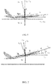
Figure 1 is a schematic view of an aircraft on the ground, showing the forces acting on the aircraft. -
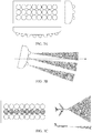
Figure 2 is a schematic view of an aircraft during the take off phase, showing the forces acting on the aircraft. -
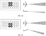
Figures 3a to 3e are different views showing the illumination of a light equipment with a matrix of LEDs in several situations. - The method for dynamic control of runway illumination on aircraft is suitable for controlling the illumination of a light equipment comprising a LED matrix and refraction optics. The following steps describe an example of the application of the method for the evaluation of a specific flight phase of the aircraft (take-off). The same methodology, but with different flight dynamic equations and sensor measurements could be used, so that it is included only as an example:
- During the take-off phase, we will consider two different situations:
- During this phase, one or all wheels are in contact with the ground (so lift is not enough for taking off). There is a normal force from the ground (N) that creates a friction against the aircraft displacement (fr). Ground and wind axis remain parallel and the angle of attack (α) is equal to the aircraft pitch (γ). Drag (D) and lift (L) forces are applied on wind axis, thrust (T) in aircraft axis and weight (W) in ground axis. These forces, which act during the ground phase, can be seen in
figure 1 . - In this scenario, the motion equations applied on wind axis are:


- During this phase, the aircraft is in the air. There is no longer a normal force and a friction force, and the wind and aircraft axis present different angles with respect to the ground (see
figure 2 ). - In this scenario, the motion equations applied on the wind axis are:


- Additionally to those equations, normal force and aerodynamic forces are dependent on angle of attack and speed through:


- Where the following parameters are considered:
- ρ is the air density - It is a known value
- S is the wing surface - It is a known value for a specific aircraft
- g is gravity acceleration (9.81 m/s2)
- CL0 is the lift coefficient for 0 angle of attack - It is a known value for a specific aircraft
- CLα is the lift coefficient parameter dependant on angle of attack - It is a known value for a specific aircraft
- CD0 is the constant drag coefficient - It is a known value for a specific aircraft
- k is the polar coefficient - It is a known value for a specific aircraft
- µ is the friction coefficient - It is a known value for a specific aircraft
- To follow a simplified approach, we will consider the coefficients CL0, CLα, CD0 and k constants during the process, although there will be second order effects as ground effect, landing gear and flaps retraction that will impact them.
- For this particular example there will be pitch rate (y-axis gyroscope) and accelerations in x and z, considering aircraft axis (as the sensors are fixed in the aircraft). These measurements are obtained from a gyroscope and two accelerometers properly oriented with the aircraft axis.
- The components used for the Kalman filter are described below:
- State of the system vector for instant t: xt
- Vector of sensor measurements: zt
- State transition model: function f() for the process and Ft for the Jacobian matrix based on it for instant t
- Observation model: function h() for the model and Ht for the Jacobian matrix based on it for instant t
- Estimated error covariance: Pt
- Covariance of the process noise: Qt
- Covariance of the observation noise: Rt
- c1) Predict phase
- (1) Predicted (a priori) state estimate from previous state: xt = f(x t-1)
- (2) Predicted (a priori) estimate error covariance:

- c2) Update phase
- (3) Measurement residual: y t = zt - h(xt )
- (4) Innovation covariance:

- (5) Optimal Kalman gain:

- (6) Updated (a posteriori) state estimate: x t+1 = xt + Ktyt
- (7) Updated (a posteriori) estimate error covariance: P t+1 = (I - KtHt )Pt
- In this example, we will use the following state variables for the vector xt:
- Aircraft ground speed (V)
- Angle between wind and ground axis (β = γ-α)
- Angle of attack (α)
- Prediction and the observation matrix are the Jacobians of the process equations.
- In order to group the number of variables, the following substitutions are done:


- To simplify, we will change the variables CL0, CLα, CD0 and k by equivalents C'L0,C'Lα,C'D0 and k'. With this change, and assuming small angles (cos α∼1 and sinα∼α), the equations used in the Kalman filter are:



- The measurements described in equation yt = zt - h(xt ) in the update phase are the data from pitch rate (y-axis gyroscope) and accelerations in x and z, considering aircraft axis (as the sensors are fixed in the aircraft). To obtain the function h that converts the state variables into measurements, we need to transfer the inertia components


- Based on this, the matrix equations described in predict and update phase will be as follows (when aircraft is on air; similar ones are obtained when aircraft is on ground):


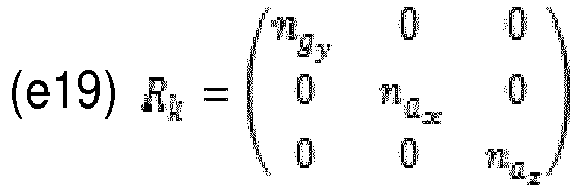
- For the process noise matrix and measurement noise matrix, we followed a very simplified approach where no interdependencies were considered, so matrices Qt-1 and Rt are simply:

- For example, the intensity, direction and the light distribution of the LEDs in the light equipment can be determined.
- In this particular example, two of the parameters included in the state vector are considered: speed (V) and pitch angle (γ). Based on these two parameters, an example of possible light control application (not intended to be limited to this example, neither with the light solution implemented) can be considered as follows:
Consider a light architecture based in a matrix of 8x3 LEDs as described infigure 3a , where each of the LEDs can be operated independently of the others in terms of power. The LEDs are oriented in a way or have an optical element that allows covering 90º in horizontal plane and 30º in vertical plane. The light could be oriented as described infigure 3b and operated as follows: - 1. During the taxi and start of the take off phase (low speeds), the pilot could be more interested in a wide short range illumination to detect runway signals. In that way, all the LEDs of the central row could be powered at less than 100 % (for instance, 25%) of their power as seen in
figure 3c - 2. As soon as speed increases, the pilot could be more interested in a narrow illumination beam to detect possible long distance obstacles, so the final illumination set up could consist of 100% power of 2 central LEDs of central and top rows as seen in
figure 3d . The transition from one configuration to the other one could be done progressively as a function of the speed (V) obtained from the Kalman filter - 3. Once the aircraft starts the rotation, the beam would no longer illuminate the runway. The runway could be kept illuminated if the LEDs used would be 100% of the 2 central LEDS of the central and bottom rows as seen in
figure 3e . The transition from one configuration to the other one could be done progressively as a function of the picth angle (γ) obtained from the Kalman filter. - The control is based only in off the shell sensors used in other general electronic market as for smartphones, etc. Those sensors could cover (not limited to): Gyroscopes, Accelerometers, GPS, magnetometers, temperature and barometric pressure sensors, etc.
- Although the present invention has been fully described in connection with preferred embodiments, it is evident that modifications may be introduced within the scope thereof, not considering this as limited by these embodiments, but by the contents of the following claims.
Claims (5)
- Method for dynamic control of runway illumination on aircraft, suitable for controlling the illumination of a light equipment comprising a LED matrix and refraction optics during a flight phase, the method comprising the following steps:a) Determination of predefined flight dynamic movement equations for the flight phaseb) Obtention of real data from autonomous sensors independent from the aircraft sensorsc) Use of extended Kalman Filter and algorithm taking into account the data from the autonomous sensors to obtain the aircraft dynamics data, this step comprising the following phases:c1) Predict phasec2) Update phased) Application of the obtained aircraft dynamics data to light control laws affecting the light equipment.
- Method for dynamic control of runway illumination on aircraft, according to claim 1, applicable during the take-off flight phase, comprising the following steps:a) Determination of predefined flight dynamic movement equations for the take-off flight phase:


 • ρ is the air density - It is a known value• S is the wing surface - It is a known value for a specific aircraft• g is gravity acceleration (9.81 m/s2)• CL0 is the lift coefficient for 0 angle of attack - It is a known value for a specific aircraft• CLα is the lift coefficient parameter dependant on angle of attack - It is a known value for a specific aircraft• CD0 is the constant drag coefficient - It is a known value for a specific aircraft• k is the polar coefficient - It is a known value for a specific aircraftwhere the following forces are considered:• D: drag• L: lift• T: thrust• W: weight.b) Obtention of real data from a y-axis gyroscope, an x-axis accelerometer and a z-axis accelerometer as autonomous sensors independent from the aircraft sensors:- the pitch rate is obtained from the y-axis gyroscope- the accelerations in x and z are obtained from the two corresponding accelerometersc) Use of extended Kalman Filter and algorithm taking into account the data from the autonomous sensors to obtain the aircraft pitch angle γ and the aircraft speed V, wherein the phases considered in the process in a sequential phase for the iterative process are as follows:c1) Predict phase• (1) Predicted (a priori) state estimate from previous state: xt = f(x t-1)• (2) Predicted (a priori) estimate error covariance:
 c2) Update phase• (3) Measurement residual: yt = zt - h(xt )• (4) Innovation covariance:
 • (5) Optimal Kalman gain:
 • (6) Updated (a posteriori) state estimate: X t+1 = Xt + KtYt• (7) Updated (a posteriori) estimate error covariance: P t+1 = (I - KtHt )Ptwherein the components used for the Kalman filter are as follows:• State of the system vector for instant t: xt• Vector of sensor measurements: zt• State transition model: function f() for the process and Ft for the Jacobian matrix based on it for instant t• Observation model: function h() for the model and Ht for the Jacobian matrix based on it for instant t• Estimated error covariance: Pt• Covariance of the process noise: Qt• Covariance of the observation noise: Rtwherein the following state variables are used for the vector xt:• Aircraft ground speed: V• Angle between wind and ground axis: β = γ-α• Angle of attack: αd) Application of the obtained pitch angle γ and the aircraft speed V to determine the intensity, direction and the light distribution of the LEDs in the light equipment.
 - Method for dynamic control of runway illumination on aircraft, according to claim 2, in which the LED matrix of the light equipment comprises several rows and columns where each of the LEDs can be operated independently of the others in terms of power, illuminating each of them different areas and wherein in function of the speed V obtained from the Kalman filter in step c) the LED matrix can change the illumination state.
- Method for dynamic control of runway illumination on aircraft, according to claim 2, in which the LED matrix of the light equipment comprises several rows and columns where each of the LEDs can be operated independently of the others in terms of power, illuminating each of them different areas and wherein in function of the pitch angle γ obtained from the Kalman filter in step c) the LED matrix can change the illumination state.
- Method for dynamic control of runway illumination on aircraft, according to claim 1, wherein the autonomous sensors are gyroscopes, accelerometers, GPS, magnetometers, temperature sensors and/or barometric pressure sensors.
Priority Applications (4)
| Application Number | Priority Date | Filing Date | Title |
|---|---|---|---|
| EP18382121.4A EP3533715B1 (en) | 2018-02-28 | 2018-02-28 | Method for dynamic control of runway illumination on aircraft |
| ES18382121T ES2837580T3 (en) | 2018-02-28 | 2018-02-28 | Method for dynamic control of aircraft runway lighting |
| US16/281,962 US10583936B2 (en) | 2018-02-28 | 2019-02-21 | Method for dynamic control of runway illumination on aircraft |
| CN201910154802.0A CN110203413A (en) | 2018-02-28 | 2019-02-28 | The dynamic control method of runway illumination |
Applications Claiming Priority (1)
| Application Number | Priority Date | Filing Date | Title |
|---|---|---|---|
| EP18382121.4A EP3533715B1 (en) | 2018-02-28 | 2018-02-28 | Method for dynamic control of runway illumination on aircraft |
Publications (2)
| Publication Number | Publication Date |
|---|---|
| EP3533715A1 true EP3533715A1 (en) | 2019-09-04 |
| EP3533715B1 EP3533715B1 (en) | 2020-09-16 |
Family
ID=62002606
Family Applications (1)
| Application Number | Title | Priority Date | Filing Date |
|---|---|---|---|
| EP18382121.4A Active EP3533715B1 (en) | 2018-02-28 | 2018-02-28 | Method for dynamic control of runway illumination on aircraft |
Country Status (4)
| Country | Link |
|---|---|
| US (1) | US10583936B2 (en) |
| EP (1) | EP3533715B1 (en) |
| CN (1) | CN110203413A (en) |
| ES (1) | ES2837580T3 (en) |
Families Citing this family (2)
| Publication number | Priority date | Publication date | Assignee | Title |
|---|---|---|---|---|
| FR3092387B1 (en) * | 2019-01-31 | 2021-01-15 | Airbus Helicopters | Directional lighting system equipping an aircraft and associated lighting method |
| JP2021195100A (en) * | 2020-06-18 | 2021-12-27 | 株式会社小糸製作所 | Aircraft lighting fixture |
Citations (6)
| Publication number | Priority date | Publication date | Assignee | Title |
|---|---|---|---|---|
| US20050090947A1 (en) * | 2003-05-13 | 2005-04-28 | Wise Kevin A. | Computational air data system for angle-of-attack and angle-of-sideslip |
| US20050240347A1 (en) * | 2004-04-23 | 2005-10-27 | Yun-Chun Yang | Method and apparatus for adaptive filter based attitude updating |
| EP2176127A2 (en) | 2007-08-15 | 2010-04-21 | Airbus Operations Ltd | Aircraft light unit |
| US20150146442A1 (en) | 2013-11-15 | 2015-05-28 | Zodiac Aero Electric | Optical lighting system for an aircraft |
| EP2995501A1 (en) | 2014-09-15 | 2016-03-16 | Goodrich Lighting Systems GmbH | Dynamic aircraft headlight and method of operating a dynamic aircraft headlight |
| EP3254972A1 (en) * | 2016-06-09 | 2017-12-13 | Goodrich Corporation | Systems and methods for dynamic light control |
-
2018
- 2018-02-28 ES ES18382121T patent/ES2837580T3/en active Active
- 2018-02-28 EP EP18382121.4A patent/EP3533715B1/en active Active
-
2019
- 2019-02-21 US US16/281,962 patent/US10583936B2/en active Active
- 2019-02-28 CN CN201910154802.0A patent/CN110203413A/en active Pending
Patent Citations (6)
| Publication number | Priority date | Publication date | Assignee | Title |
|---|---|---|---|---|
| US20050090947A1 (en) * | 2003-05-13 | 2005-04-28 | Wise Kevin A. | Computational air data system for angle-of-attack and angle-of-sideslip |
| US20050240347A1 (en) * | 2004-04-23 | 2005-10-27 | Yun-Chun Yang | Method and apparatus for adaptive filter based attitude updating |
| EP2176127A2 (en) | 2007-08-15 | 2010-04-21 | Airbus Operations Ltd | Aircraft light unit |
| US20150146442A1 (en) | 2013-11-15 | 2015-05-28 | Zodiac Aero Electric | Optical lighting system for an aircraft |
| EP2995501A1 (en) | 2014-09-15 | 2016-03-16 | Goodrich Lighting Systems GmbH | Dynamic aircraft headlight and method of operating a dynamic aircraft headlight |
| EP3254972A1 (en) * | 2016-06-09 | 2017-12-13 | Goodrich Corporation | Systems and methods for dynamic light control |
Also Published As
| Publication number | Publication date |
|---|---|
| ES2837580T3 (en) | 2021-06-30 |
| CN110203413A (en) | 2019-09-06 |
| EP3533715B1 (en) | 2020-09-16 |
| US20190263536A1 (en) | 2019-08-29 |
| US10583936B2 (en) | 2020-03-10 |
Similar Documents
| Publication | Publication Date | Title |
|---|---|---|
| ES2656326T3 (en) | Traffic aircraft separation system | |
| JP2952397B2 (en) | Active air control aircraft using air speed vector measurement device | |
| RU2550887C2 (en) | On-board integrated crew support information system and cognitive format of presenting flight information at take-off phase of multi-engine aircraft | |
| CN1957267B (en) | Upward Turbulence Prediction System for Aircraft | |
| JP7097052B2 (en) | Airplane gust response mitigation system and airplane gust response mitigation method | |
| EP3254972B1 (en) | Systems and methods for dynamic light control | |
| US20120209457A1 (en) | Aircraft Traffic Separation System | |
| US9472107B2 (en) | Method and device for determining a control set point of an aircraft, associated computer program and aircraft | |
| US9856032B2 (en) | Method and device for controlling at least one actuator control system of an aircraft, associated computer program product and aircraft | |
| JP5083466B2 (en) | Flight state control device for flying object | |
| US20020036573A1 (en) | Aircraft display with potential thrust indicator | |
| JP2005297922A (en) | Aircraft automatic take-off device, automatic landing device, automatic take-off and landing device, aircraft automatic take-off method, automatic landing method, and automatic take-off and landing method | |
| US20160221663A1 (en) | Flight control computer for an aircraft that includes an inertial sensor incorporated therein | |
| US9085371B2 (en) | Automatic throttle roll angle compensation | |
| FR3013466A1 (en) | METHOD FOR DETERMINING AN AIRCRAFT RESULTING TRACK, APPARATUS AND COMPUTER PROGRAM PRODUCT THEREOF | |
| US10583936B2 (en) | Method for dynamic control of runway illumination on aircraft | |
| Steinleitner et al. | Automatic take-off and landing of tailwheel aircraft with incremental nonlinear dynamic inversion | |
| CN105292472A (en) | Multi-purpose flexible-wing unmanned aerial vehicle | |
| FR3110004A1 (en) | Control method of a robot-aircraft and corresponding control system | |
| US12509243B2 (en) | Automated towed glider control system | |
| KR101749983B1 (en) | Method for calculating landing gear deflection of air vehicle using position information | |
| CN204021249U (en) | The soft wing unmanned plane of high-mobility, multipurpose, wheeled vehicle | |
| Elfes et al. | Modelling, control and perception for an autonomous robotic airship | |
| KR100472968B1 (en) | Autonomous Take-Off and Landing System for Large-Class Unmanned Airship | |
| Ottander et al. | Precision slung cargo delivery onto a moving platform |
Legal Events
| Date | Code | Title | Description |
|---|---|---|---|
| PUAI | Public reference made under article 153(3) epc to a published international application that has entered the european phase |
Free format text: ORIGINAL CODE: 0009012 |
|
| STAA | Information on the status of an ep patent application or granted ep patent |
Free format text: STATUS: THE APPLICATION HAS BEEN PUBLISHED |
|
| AK | Designated contracting states |
Kind code of ref document: A1 Designated state(s): AL AT BE BG CH CY CZ DE DK EE ES FI FR GB GR HR HU IE IS IT LI LT LU LV MC MK MT NL NO PL PT RO RS SE SI SK SM TR |
|
| AX | Request for extension of the european patent |
Extension state: BA ME |
|
| STAA | Information on the status of an ep patent application or granted ep patent |
Free format text: STATUS: REQUEST FOR EXAMINATION WAS MADE |
|
| 17P | Request for examination filed |
Effective date: 20200214 |
|
| RBV | Designated contracting states (corrected) |
Designated state(s): AL AT BE BG CH CY CZ DE DK EE ES FI FR GB GR HR HU IE IS IT LI LT LU LV MC MK MT NL NO PL PT RO RS SE SI SK SM TR |
|
| GRAP | Despatch of communication of intention to grant a patent |
Free format text: ORIGINAL CODE: EPIDOSNIGR1 |
|
| STAA | Information on the status of an ep patent application or granted ep patent |
Free format text: STATUS: GRANT OF PATENT IS INTENDED |
|
| INTG | Intention to grant announced |
Effective date: 20200515 |
|
| RIN1 | Information on inventor provided before grant (corrected) |
Inventor name: ROBLEDO BUENO, JESUS |
|
| GRAS | Grant fee paid |
Free format text: ORIGINAL CODE: EPIDOSNIGR3 |
|
| GRAA | (expected) grant |
Free format text: ORIGINAL CODE: 0009210 |
|
| STAA | Information on the status of an ep patent application or granted ep patent |
Free format text: STATUS: THE PATENT HAS BEEN GRANTED |
|
| AK | Designated contracting states |
Kind code of ref document: B1 Designated state(s): AL AT BE BG CH CY CZ DE DK EE ES FI FR GB GR HR HU IE IS IT LI LT LU LV MC MK MT NL NO PL PT RO RS SE SI SK SM TR |
|
| REG | Reference to a national code |
Ref country code: GB Ref legal event code: FG4D |
|
| REG | Reference to a national code |
Ref country code: CH Ref legal event code: EP |
|
| REG | Reference to a national code |
Ref country code: DE Ref legal event code: R096 Ref document number: 602018007898 Country of ref document: DE |
|
| REG | Reference to a national code |
Ref country code: IE Ref legal event code: FG4D |
|
| REG | Reference to a national code |
Ref country code: AT Ref legal event code: REF Ref document number: 1313969 Country of ref document: AT Kind code of ref document: T Effective date: 20201015 |
|
| PG25 | Lapsed in a contracting state [announced via postgrant information from national office to epo] |
Ref country code: BG Free format text: LAPSE BECAUSE OF FAILURE TO SUBMIT A TRANSLATION OF THE DESCRIPTION OR TO PAY THE FEE WITHIN THE PRESCRIBED TIME-LIMIT Effective date: 20201216 Ref country code: HR Free format text: LAPSE BECAUSE OF FAILURE TO SUBMIT A TRANSLATION OF THE DESCRIPTION OR TO PAY THE FEE WITHIN THE PRESCRIBED TIME-LIMIT Effective date: 20200916 Ref country code: FI Free format text: LAPSE BECAUSE OF FAILURE TO SUBMIT A TRANSLATION OF THE DESCRIPTION OR TO PAY THE FEE WITHIN THE PRESCRIBED TIME-LIMIT Effective date: 20200916 Ref country code: GR Free format text: LAPSE BECAUSE OF FAILURE TO SUBMIT A TRANSLATION OF THE DESCRIPTION OR TO PAY THE FEE WITHIN THE PRESCRIBED TIME-LIMIT Effective date: 20201217 Ref country code: SE Free format text: LAPSE BECAUSE OF FAILURE TO SUBMIT A TRANSLATION OF THE DESCRIPTION OR TO PAY THE FEE WITHIN THE PRESCRIBED TIME-LIMIT Effective date: 20200916 Ref country code: NO Free format text: LAPSE BECAUSE OF FAILURE TO SUBMIT A TRANSLATION OF THE DESCRIPTION OR TO PAY THE FEE WITHIN THE PRESCRIBED TIME-LIMIT Effective date: 20201216 |
|
| REG | Reference to a national code |
Ref country code: AT Ref legal event code: MK05 Ref document number: 1313969 Country of ref document: AT Kind code of ref document: T Effective date: 20200916 |
|
| REG | Reference to a national code |
Ref country code: NL Ref legal event code: MP Effective date: 20200916 |
|
| PG25 | Lapsed in a contracting state [announced via postgrant information from national office to epo] |
Ref country code: RS Free format text: LAPSE BECAUSE OF FAILURE TO SUBMIT A TRANSLATION OF THE DESCRIPTION OR TO PAY THE FEE WITHIN THE PRESCRIBED TIME-LIMIT Effective date: 20200916 Ref country code: LV Free format text: LAPSE BECAUSE OF FAILURE TO SUBMIT A TRANSLATION OF THE DESCRIPTION OR TO PAY THE FEE WITHIN THE PRESCRIBED TIME-LIMIT Effective date: 20200916 |
|
| REG | Reference to a national code |
Ref country code: LT Ref legal event code: MG4D |
|
| PG25 | Lapsed in a contracting state [announced via postgrant information from national office to epo] |
Ref country code: RO Free format text: LAPSE BECAUSE OF FAILURE TO SUBMIT A TRANSLATION OF THE DESCRIPTION OR TO PAY THE FEE WITHIN THE PRESCRIBED TIME-LIMIT Effective date: 20200916 Ref country code: PT Free format text: LAPSE BECAUSE OF FAILURE TO SUBMIT A TRANSLATION OF THE DESCRIPTION OR TO PAY THE FEE WITHIN THE PRESCRIBED TIME-LIMIT Effective date: 20210118 Ref country code: CZ Free format text: LAPSE BECAUSE OF FAILURE TO SUBMIT A TRANSLATION OF THE DESCRIPTION OR TO PAY THE FEE WITHIN THE PRESCRIBED TIME-LIMIT Effective date: 20200916 Ref country code: EE Free format text: LAPSE BECAUSE OF FAILURE TO SUBMIT A TRANSLATION OF THE DESCRIPTION OR TO PAY THE FEE WITHIN THE PRESCRIBED TIME-LIMIT Effective date: 20200916 Ref country code: LT Free format text: LAPSE BECAUSE OF FAILURE TO SUBMIT A TRANSLATION OF THE DESCRIPTION OR TO PAY THE FEE WITHIN THE PRESCRIBED TIME-LIMIT Effective date: 20200916 Ref country code: SM Free format text: LAPSE BECAUSE OF FAILURE TO SUBMIT A TRANSLATION OF THE DESCRIPTION OR TO PAY THE FEE WITHIN THE PRESCRIBED TIME-LIMIT Effective date: 20200916 |
|
| PG25 | Lapsed in a contracting state [announced via postgrant information from national office to epo] |
Ref country code: PL Free format text: LAPSE BECAUSE OF FAILURE TO SUBMIT A TRANSLATION OF THE DESCRIPTION OR TO PAY THE FEE WITHIN THE PRESCRIBED TIME-LIMIT Effective date: 20200916 Ref country code: IS Free format text: LAPSE BECAUSE OF FAILURE TO SUBMIT A TRANSLATION OF THE DESCRIPTION OR TO PAY THE FEE WITHIN THE PRESCRIBED TIME-LIMIT Effective date: 20210116 Ref country code: AT Free format text: LAPSE BECAUSE OF FAILURE TO SUBMIT A TRANSLATION OF THE DESCRIPTION OR TO PAY THE FEE WITHIN THE PRESCRIBED TIME-LIMIT Effective date: 20200916 Ref country code: AL Free format text: LAPSE BECAUSE OF FAILURE TO SUBMIT A TRANSLATION OF THE DESCRIPTION OR TO PAY THE FEE WITHIN THE PRESCRIBED TIME-LIMIT Effective date: 20200916 |
|
| REG | Reference to a national code |
Ref country code: DE Ref legal event code: R097 Ref document number: 602018007898 Country of ref document: DE |
|
| PG25 | Lapsed in a contracting state [announced via postgrant information from national office to epo] |
Ref country code: SK Free format text: LAPSE BECAUSE OF FAILURE TO SUBMIT A TRANSLATION OF THE DESCRIPTION OR TO PAY THE FEE WITHIN THE PRESCRIBED TIME-LIMIT Effective date: 20200916 |
|
| REG | Reference to a national code |
Ref country code: ES Ref legal event code: FG2A Ref document number: 2837580 Country of ref document: ES Kind code of ref document: T3 Effective date: 20210630 |
|
| PLBE | No opposition filed within time limit |
Free format text: ORIGINAL CODE: 0009261 |
|
| STAA | Information on the status of an ep patent application or granted ep patent |
Free format text: STATUS: NO OPPOSITION FILED WITHIN TIME LIMIT |
|
| 26N | No opposition filed |
Effective date: 20210617 |
|
| PG25 | Lapsed in a contracting state [announced via postgrant information from national office to epo] |
Ref country code: DK Free format text: LAPSE BECAUSE OF FAILURE TO SUBMIT A TRANSLATION OF THE DESCRIPTION OR TO PAY THE FEE WITHIN THE PRESCRIBED TIME-LIMIT Effective date: 20200916 Ref country code: SI Free format text: LAPSE BECAUSE OF FAILURE TO SUBMIT A TRANSLATION OF THE DESCRIPTION OR TO PAY THE FEE WITHIN THE PRESCRIBED TIME-LIMIT Effective date: 20200916 |
|
| PG25 | Lapsed in a contracting state [announced via postgrant information from national office to epo] |
Ref country code: MC Free format text: LAPSE BECAUSE OF FAILURE TO SUBMIT A TRANSLATION OF THE DESCRIPTION OR TO PAY THE FEE WITHIN THE PRESCRIBED TIME-LIMIT Effective date: 20200916 |
|
| REG | Reference to a national code |
Ref country code: BE Ref legal event code: MM Effective date: 20210228 |
|
| PG25 | Lapsed in a contracting state [announced via postgrant information from national office to epo] |
Ref country code: CH Free format text: LAPSE BECAUSE OF NON-PAYMENT OF DUE FEES Effective date: 20210228 Ref country code: LU Free format text: LAPSE BECAUSE OF NON-PAYMENT OF DUE FEES Effective date: 20210228 Ref country code: LI Free format text: LAPSE BECAUSE OF NON-PAYMENT OF DUE FEES Effective date: 20210228 Ref country code: IT Free format text: LAPSE BECAUSE OF FAILURE TO SUBMIT A TRANSLATION OF THE DESCRIPTION OR TO PAY THE FEE WITHIN THE PRESCRIBED TIME-LIMIT Effective date: 20200916 |
|
| PG25 | Lapsed in a contracting state [announced via postgrant information from national office to epo] |
Ref country code: IE Free format text: LAPSE BECAUSE OF NON-PAYMENT OF DUE FEES Effective date: 20210228 |
|
| PG25 | Lapsed in a contracting state [announced via postgrant information from national office to epo] |
Ref country code: BE Free format text: LAPSE BECAUSE OF NON-PAYMENT OF DUE FEES Effective date: 20210228 |
|
| PG25 | Lapsed in a contracting state [announced via postgrant information from national office to epo] |
Ref country code: NL Free format text: LAPSE BECAUSE OF NON-PAYMENT OF DUE FEES Effective date: 20200923 Ref country code: CY Free format text: LAPSE BECAUSE OF FAILURE TO SUBMIT A TRANSLATION OF THE DESCRIPTION OR TO PAY THE FEE WITHIN THE PRESCRIBED TIME-LIMIT Effective date: 20200916 |
|
| PG25 | Lapsed in a contracting state [announced via postgrant information from national office to epo] |
Ref country code: HU Free format text: LAPSE BECAUSE OF FAILURE TO SUBMIT A TRANSLATION OF THE DESCRIPTION OR TO PAY THE FEE WITHIN THE PRESCRIBED TIME-LIMIT; INVALID AB INITIO Effective date: 20180228 |
|
| PG25 | Lapsed in a contracting state [announced via postgrant information from national office to epo] |
Ref country code: MK Free format text: LAPSE BECAUSE OF FAILURE TO SUBMIT A TRANSLATION OF THE DESCRIPTION OR TO PAY THE FEE WITHIN THE PRESCRIBED TIME-LIMIT Effective date: 20200916 |
|
| PG25 | Lapsed in a contracting state [announced via postgrant information from national office to epo] |
Ref country code: MT Free format text: LAPSE BECAUSE OF FAILURE TO SUBMIT A TRANSLATION OF THE DESCRIPTION OR TO PAY THE FEE WITHIN THE PRESCRIBED TIME-LIMIT Effective date: 20200916 |
|
| PGFP | Annual fee paid to national office [announced via postgrant information from national office to epo] |
Ref country code: ES Payment date: 20250331 Year of fee payment: 8 |
|
| PG25 | Lapsed in a contracting state [announced via postgrant information from national office to epo] |
Ref country code: TR Free format text: LAPSE BECAUSE OF FAILURE TO SUBMIT A TRANSLATION OF THE DESCRIPTION OR TO PAY THE FEE WITHIN THE PRESCRIBED TIME-LIMIT Effective date: 20200916 |
|
| PGFP | Annual fee paid to national office [announced via postgrant information from national office to epo] |
Ref country code: GB Payment date: 20260219 Year of fee payment: 9 |
|
| PGFP | Annual fee paid to national office [announced via postgrant information from national office to epo] |
Ref country code: DE Payment date: 20260218 Year of fee payment: 9 |
|
| PGFP | Annual fee paid to national office [announced via postgrant information from national office to epo] |
Ref country code: FR Payment date: 20260218 Year of fee payment: 9 |