EP3533651A1 - Multi-directional input device - Google Patents
Multi-directional input device Download PDFInfo
- Publication number
- EP3533651A1 EP3533651A1 EP17865025.5A EP17865025A EP3533651A1 EP 3533651 A1 EP3533651 A1 EP 3533651A1 EP 17865025 A EP17865025 A EP 17865025A EP 3533651 A1 EP3533651 A1 EP 3533651A1
- Authority
- EP
- European Patent Office
- Prior art keywords
- actuator
- input device
- rotating body
- directional input
- indicated
- Prior art date
- Legal status (The legal status is an assumption and is not a legal conclusion. Google has not performed a legal analysis and makes no representation as to the accuracy of the status listed.)
- Granted
Links
Images


Classifications
-
- B—PERFORMING OPERATIONS; TRANSPORTING
- B60—VEHICLES IN GENERAL
- B60K—ARRANGEMENT OR MOUNTING OF PROPULSION UNITS OR OF TRANSMISSIONS IN VEHICLES; ARRANGEMENT OR MOUNTING OF PLURAL DIVERSE PRIME-MOVERS IN VEHICLES; AUXILIARY DRIVES FOR VEHICLES; INSTRUMENTATION OR DASHBOARDS FOR VEHICLES; ARRANGEMENTS IN CONNECTION WITH COOLING, AIR INTAKE, GAS EXHAUST OR FUEL SUPPLY OF PROPULSION UNITS IN VEHICLES
- B60K20/00—Arrangement or mounting of change-speed gearing control devices in vehicles
- B60K20/02—Arrangement or mounting of change-speed gearing control devices in vehicles of initiating means
-
- G—PHYSICS
- G05—CONTROLLING; REGULATING
- G05G—CONTROL DEVICES OR SYSTEMS INSOFAR AS CHARACTERISED BY MECHANICAL FEATURES ONLY
- G05G25/00—Other details or appurtenances of control mechanisms, e.g. supporting intermediate members elastically
-
- G—PHYSICS
- G05—CONTROLLING; REGULATING
- G05G—CONTROL DEVICES OR SYSTEMS INSOFAR AS CHARACTERISED BY MECHANICAL FEATURES ONLY
- G05G5/00—Means for preventing, limiting or returning the movements of parts of a control mechanism, e.g. locking controlling member
- G05G5/03—Means for enhancing the operator's awareness of arrival of the controlling member at a command or datum position; Providing feel, e.g. means for creating a counterforce
-
- G—PHYSICS
- G05—CONTROLLING; REGULATING
- G05G—CONTROL DEVICES OR SYSTEMS INSOFAR AS CHARACTERISED BY MECHANICAL FEATURES ONLY
- G05G9/00—Manually-actuated control mechanisms provided with one single controlling member co-operating with two or more controlled members, e.g. selectively, simultaneously
- G05G9/02—Manually-actuated control mechanisms provided with one single controlling member co-operating with two or more controlled members, e.g. selectively, simultaneously the controlling member being movable in different independent ways, movement in each individual way actuating one controlled member only
- G05G9/04—Manually-actuated control mechanisms provided with one single controlling member co-operating with two or more controlled members, e.g. selectively, simultaneously the controlling member being movable in different independent ways, movement in each individual way actuating one controlled member only in which movement in two or more ways can occur simultaneously
- G05G9/047—Manually-actuated control mechanisms provided with one single controlling member co-operating with two or more controlled members, e.g. selectively, simultaneously the controlling member being movable in different independent ways, movement in each individual way actuating one controlled member only in which movement in two or more ways can occur simultaneously the controlling member being movable by hand about orthogonal axes, e.g. joysticks
-
- H—ELECTRICITY
- H01—ELECTRIC ELEMENTS
- H01H—ELECTRIC SWITCHES; RELAYS; SELECTORS; EMERGENCY PROTECTIVE DEVICES
- H01H25/00—Switches with compound movement of handle or other operating part
- H01H25/04—Operating part movable angularly in more than one plane, e.g. joystick
Definitions
- the present invention relates to a multi-directional input device, and more particularly to a multi-directional input device that switches the transmission of a vehicle.
- a multi-directional input device that switches the transmission of a vehicle by switching the shift position of a manipulation lever.
- a mechanism that generates a manipulation feeling is provided to have the manipulator get a feel for the change of the shift position.
- the multi-directional input device described in PTL 1 has a sliding spherical surface that is shaped like a spherical body and rotates at a fixed position, a manipulation lever fixed to the sliding spherical surface, a pin that moves together with the manipulation lever at a position distant from the sliding spherical surface, and a cam surface positioned on the travel path of the pin.
- the multi-directional input device in PTL 1 has the disadvantage that since the pin is provided at a position distant from the sliding spherical surface, the entire dimension becomes large.
- the multi-directional input device also has the disadvantage that since the pin is far away from the center of the rotation, the dimension of the cam surface is large and the entire dimension becomes further large.
- the present invention addresses the above situation with the object of providing a multi-directional input device that can give a manipulation feeling to the manipulator while achieving a smaller size than before.
- the present invention is a multi-directional input device that has a rotating body that includes a sliding surface forming at least part of a virtual spherical surface and also includes a storage part recessed from the outside of the virtual spherical surface toward the inside, a support body that rotatably supports the rotating body by slidably supporting the sliding surface, an actuator that is at least partially stored in the storage part, a cam part that abuts the actuator, an elastic member that urges the actuator between the rotating body and the actuator toward the cam part, and a manipulation lever that rotates together with the rotating body and can be manipulated to shift to a plurality of shift positions.
- the actuator is at least partially stored in the storage part of the rotating body, the distance from the rotating body to the cam part can be shortened when compared with a case in which the actuator is at a position distant from the rotating body, so a manipulation feeling can be given to the manipulator while achieving a smaller size than before.
- the elastic member is at least partially stored in the storage part.
- the actuator and elastic member are at least partially stored in the storage part of the rotating body, the distance from the rotating body to the cam part can be shortened when compared with a case in which at least one of the actuator and elastic member is at a position distant from the rotating body, so a manipulation feeling can be given to the manipulator while achieving a smaller size than before.
- the cam part and support body are formed integrally with each other.
- cam part and support body are formed integrally with each other, a smaller size can be achieved and the number of parts can be reduced when compared with a case in which separate members are combined.
- the storage part includes an inner wall that slidably supports the actuator and the actuator travels along the inner wall.
- the storage part since the storage part includes an inner wall that slidably supports the actuator and the actuator travels along the inner wall, a smaller size can be achieved when compared with a case in which a part used to guide the actuator is provided separately.
- a support axis extending from the inside of the storage part to the outside of the rotating body is further provided, the actuator has a through-hole, at least part of the support axis is slidably positioned in the through-hole, and the actuator travels along the support axis.
- a position detecting unit is further provided that detects a shift position according to the position of the support axis.
- a position detecting unit is further provided that detects a shift position according to the position of the support axis, a smaller size can be achieved when compared with a case in which a separate part used to detect a shift position is provided.
- a manipulation feeling can be given to the manipulator while achieving a smaller size than before.
- FIG. 1 is a perspective view of the multi-directional input device 100 according to this embodiment.
- the multi-directional input device 100 includes a case 110 that is fixed to a vehicle and accommodates part of the constituent elements of the multi-directional input device 100, and also includes a manipulation lever 120 that can travel relative to the case 110. Most of the manipulation lever 120 is positioned outside the case 110.
- the manipulation lever 120 includes a manipulation cover 128 that the driver of the vehicle can hold.
- the manipulation lever 120 can be inclined at a plurality of shift position with respect to the case 110 by being manually manipulated by the driver of the vehicle.
- the multi-directional input device 100 switches the transmission of the vehicle by sending an electronic signal corresponding to the shift position of the manipulation lever 120 to a control device in the vehicle.
- an x direction, a y direction, and a z direction which are mutually orthogonal, are defined.
- the x direction is represented without distinguishing between an x1 direction and an x2 direction, which are mutually opposite.
- the y direction is represented without distinguishing between a y1 direction and y2 direction, which are mutually opposite.
- the z direction is represented without distinguishing between a z1 direction and z2 direction, which are mutually opposite.
- the z1 direction will sometimes be referred to as the upper direction and the z2 direction will sometimes be referred to as the lower direction.
- Fig. 2 is a perspective view of the multi-directional input device 100 with the case 110 ( Fig. 1 ) omitted.
- the multi-directional input device 100 further includes a support body 130 and a position detecting unit 140.
- Most of the support body 130 is positioned in the case 110 ( Fig. 1 ) and is fixed to the case 110 ( Fig. 1 ).
- the whole of the position detecting unit 140 is positioned in the case 110 ( Fig. 1 ).
- the position detecting unit 140 is partially fixed to the case 110 ( Fig. 1 ) outside the support body 130.
- the position detecting unit 140 detects the shift position of the manipulation lever 120.
- Fig. 3 is a perspective view of the multi-directional input device 100 with the case 110 and manipulation cover 128 indicated in Fig. 1 omitted.
- Fig. 4 is a rear view of the multi-directional input device 100 with the case 110 and manipulation cover 128 indicated in Fig. 1 omitted.
- Fig. 5 is a side view of the multi-directional input device 100 with the case 110 and manipulation cover 128 indicated in Fig. 1 omitted.
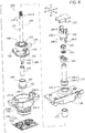
- Fig. 6 and Fig. 7 are an exploded perspective view of the multi-directional input device 100 with the case 110 and manipulation cover 128 indicated in Fig. 1 omitted.
- Fig. 6 is a drawing when viewed from the z1 side.
- Fig. 7 is a drawing when viewed from the z2 side.
- Fig. 8 is a cross-sectional view when a cross section parallel to a zx plane passing through the line 8-8 in Fig. 4 is viewed from the y2 side in the y1 direction.
- an internal space 133 is provided in the support body 130.
- the multi-directional input device 100 further includes a rotating body 150, an actuator 160, a first elastic member 171, a second elastic member 172, and a support axis 180, which are as indicated in Fig. 6 , in the internal space 133.
- a rotating body 150 an actuator 160, a first elastic member 171, a second elastic member 172, and a support axis 180, which are as indicated in Fig. 6 , in the internal space 133.
- the support body 130 includes a first support body 131 on the z1 side and a second support body 132 on the z2 side.
- the first support body 131 and second support body 132 are mutually fixed with screws that are not indicated in the drawing.
- a first upper opening 131-1 is provided on the z1 side.
- the first upper opening 131-1 is provided at an end of the internal space 133 on the z1 side, making the internal space 133 open in the z1 direction.
- the first upper opening 131-1 is a discoid space that is short in the z direction and expands in directions substantially orthogonal to the z direction.
- a first lower opening 131-2 is provided on the z2 side.
- the first lower opening 131-2 is provided at an intermediate point in the internal space 133 in the z direction, and faces the second support body 132.
- the first lower opening 131-2 has a size that enables part of the rotating body 150 to be accommodated in the internal space 133 in the first support body 131 from the z2 side.
- the first support body 131 has a first sliding support surface 131-3 between the first upper opening 131-1 and the first lower opening 131-2 in the z direction, the first sliding support surface 131-3 facing the internal space 133.
- the first sliding support surface 131-3 is part of a ring-shaped surface obtained by cutting a half of one virtual spherical surface on the z1 side with two planes parallel to an xy plane. In a direction orthogonal to the z direction, the size of an edge of the first sliding support surface 131-3 on the z2 side is substantially the same as the size of the first lower opening 131-2.
- a space between the first upper opening 131-1 and the first sliding support surface 131-3 in the internal space 133 is wider than the first upper opening 131-1 and is narrower than an end of the first sliding support surface 131-3 on the z1 side.
- Fig. 9 is a perspective view of the second support body 132 when viewed from the x1 side.
- Fig. 10 is a perspective view of the second support body 132 when viewed from the x2 side.
- a second upper opening 132-1 is provided on the z1 side.
- the second upper opening 132-1 is provided at an intermediate point in the internal space 133 in the z direction, and faces the first support body 131.
- the second upper opening 132-1 has a size that enables part of the rotating body 150 to be accommodated in the internal space 133 in the second support body 132 from the z1 side.
- the first lower opening 131-2 and second upper opening 132-1 have substantially the same size and are in tight contact with each other in the z direction.
- a second lower opening 132-2 is provided on the z2 side.
- the second lower opening 132-2 is in a substantially T shape extending in three directions, y1 direction, y2 direction and x2 direction, when viewed from the z direction.
- the second lower opening 132-2 is provided at an end of the internal space 133 on the z2 side, making the internal space 133 open in the z2 direction.
- the second support body 132 has a second sliding support surface 132-3 between the second upper opening 132-1 and the second lower opening 132-2 in the z direction, the second sliding support surface 132-3 facing the internal space 133.
- the second sliding support surface 132-3 is part of a ring-shaped surface obtained by cutting a half of one virtual spherical surface on the z2 side with two planes parallel to an xy plane. In a direction orthogonal to the z direction, the size of an edge of the second sliding support surface 132-3 on the z1 side is substantially the same as the size of the second upper opening 132-1.
- the diameter of the virtual spherical surface that defines the second sliding support surface 132-3 is larger than the diameter of the virtual spherical surface that defines the first sliding support surface 131-3.
- the center position of the virtual spherical surface that defines the second sliding support surface 132-3 is substantially the same as the center position of the virtual spherical surface that defines the first sliding support surface 131-3.
- the second support body 132 has a cam part 132-4 between the second sliding support surface 132-3 and the second lower opening 132-2 in the z direction, the cam part 132-4 facing the internal space 133.
- the cam part 132-4 has a concave portion and a convex portion that are oriented toward the internal space 133.
- the extent of the cam part 132-4 in directions orthogonal to the z direction varies depending on the position in the z direction.
- the cam part 132-4 and support body 130 are formed integrally with each other.
- the concave portion and convex portion of the cam part 132-4 are formed on the y1-side inner surface, y2-side inner surface, and x2-side inner surface of the second support body 132.
- the concave portion and convex portion of the cam part 132-4 are not provided on the x1-side inner surface of the second support body 132.
- Fig. 11 is a cross-sectional view when a cross section parallel to a yz plane passing through the line 11-11 in Fig. 5 is viewed from the x1 side in the x2 direction.
- the second support body 132 includes, in the vicinity of the second upper opening 132-1, a first groove 132-5 recessed from the y1-side edge of the second upper opening 132-1 in the y1 direction and a second groove 132-6 recessed from the y2-side edge of the second upper opening 132-1 in the y2 direction.
- Fig. 9 the second support body 132 includes, in the vicinity of the second upper opening 132-1, a first groove 132-5 recessed from the y1-side edge of the second upper opening 132-1 in the y1 direction and a second groove 132-6 recessed from the y2-side edge of the second upper opening 132-1 in the y2 direction.
- first groove 132-5 and second groove 132-6 are open in the z1 direction when the second support body 132 is alone, they are covered by the first support body 131 in a state in which the second support body 132 is combined with the first support body 131.
- Fig. 12 is a perspective view of the rotating body 150 and a manipulation axis 121, which will be described later, when viewed from the z1 side.
- Fig. 13 is a perspective view of the rotating body 150, the manipulation axis 121, which will be described later, and a support axis 180, which will be described later, when viewed from the z2 side.
- the rotating body 150 includes a first spherical part 151, a second spherical part 152, a connecting part 153, a first protrusion 154, and a second protrusion 155.
- the first spherical part 151 includes a first upper surface 151-1, on the z1 side, which is substantially parallel to an xy plane, a first lower surface 151-2, on the z2 side, which is substantially parallel to an xy plane, and a first sliding surface 151-3.
- the first sliding surface 151-3 is part of a surface obtained by cutting a half of one virtual spherical surface on the z1 side with the first upper surface 151-1 and first lower surface 151-2.
- the first spherical part 151 includes an axial hole 151-4 that is in a substantially cylindrical shape and is recessed from the center of the first upper surface 151-1 in a substantially circular shape in the z2 direction.
- the second spherical part 152 includes a second upper surface 152-1 that is on the z1 side and is substantially parallel to an xy plane, a second lower surface 152-2 that is on the z2 side and is substantially parallel to an xy plane, and a second sliding surface 152-3.
- the second sliding surface 152-3 is part of a surface obtained by cutting a half of one virtual spherical surface on the z2 side with the second upper surface 152-1 and second lower surface 152-2.
- the second spherical part 152 includes a storage part 152-4 that is in a substantially cylindrical shape and is recessed from the center of the second lower surface 152-2 in a substantially circular shape in the z1 direction.
- the storage part 152-4 is recessed from the outside of a virtual spherical surface that defines the second sliding surface 152-3 toward the inside.
- the storage part 152-4 has an inner wall 152-5 that is in a cylindrical shape and has a central axis parallel to the z direction.
- the first sliding surface 151-3 and second sliding surface 152-3 each form at least part of a different virtual spherical surface.
- the diameter of the virtual spherical surface that defines the first sliding surface 151-3 is substantially the same as the diameter of the virtual spherical surface that defines the first sliding support surface 131-3, but is slightly smaller.
- the diameter of the virtual spherical surface that defines the second sliding surface 152-3 is substantially the same as the diameter of the virtual spherical surface that defines the second sliding support surface 132-3, but is slightly smaller.
- the center position of the virtual spherical surface that defines the first sliding surface 151-3, the center position of the virtual spherical surface that defines the first sliding support surface 131-3, the center position of the virtual spherical surface that defines the second sliding surface 152-3, and the center position of the virtual spherical surface that defines the second sliding support surface 132-3 are substantially the same.
- the first sliding surface 151-3 slides along the first sliding support surface 131-3.
- the second sliding surface 152-3 slides along the second sliding support surface 132-3. That is, the support body 130 supports the rotating body 150 so as to be rotatable around one center by slidably supporting the first sliding surface 151-3 and second sliding surface 152-3.
- the connecting part 153 connects between the first spherical part 151 and the second spherical part 152 in the z direction.
- the second spherical part 152 is positioned on the z2 side of the first spherical part 151.
- the first protrusion 154 protrudes from the y1 side of the first spherical part 151 in the y1 direction, has a central axis parallel to the y direction, and is in a substantially cylindrical shape.
- the second protrusion 155 protrudes from the y2 side of the first spherical part 151 in the y2 direction, has a central axis parallel to the y direction, and is in a substantially cylindrical shape.
- the first protrusion 154 is positioned in the first groove 132-5.
- the second protrusion 155 is positioned in the second groove 132-6.
- the rotating body 150 rotates around a rotational axis parallel to the x direction, the travel of the first protrusion 154 is restricted to between the first groove 132-5 and the first support body 131 and the travel of the second protrusion 155 is restricted to between the second groove 132-6 and the second support body 132, so the amount of rotation of the rotating body 150 is restricted.
- the first protrusion 154 can hardly travel in the x direction in the first groove 132-5 and the second protrusion 155 can hardly travel in the x direction in the second groove 132-6.
- the rotating body 150 rotates around a rotational axis parallel to the y direction, the rotating body 150 rotates around the first protrusion 154 and second protrusion 155.
- the support axis 180 extends from an end in the storage part 152-4 in the rotating body 150 on the z1 side toward the z2 direction to the outside of the rotating body 150.
- the support axis 180 includes a columnar part 181, on the z1 side, that has a central axis along the z direction, and also includes a quadratic prism 182, on the z2 side, that has a central axis along the z direction.
- the central axes of the columnar part 181 and quadratic prism 182 pass through the center of the rotation of the rotating body 150.
- the columnar part 181 extends from the interior of the storage part 152-4 to the vicinity of the second lower opening 132-2 of the second support body 132 in the internal space 133.
- the diameter of the columnar part 181 is smaller than the diameter of the inner wall 152-5 in the storage part 152-4.
- the quadratic prism 182 extends from an end of the columnar part 181 on the z2 side through the second lower opening 132-2 to the outside of the second support body 132.
- the actuator 160 includes a cylindrical part 161 that is in a substantially cylindrical shape and has a central axis in the z direction, and also includes an abutting part 162 that is in a ring shape and protrudes from an end of the cylindrical part 161 on the z2 side in a direction orthogonal to the z direction.
- the actuator 160 has a through-hole 163 that passes through the cylindrical part 161 and abutting part 162 in the z direction.
- the through-hole 163 is in a substantially cylindrical shape and has an axis in the z direction; the diameter of the through-hole 163 changes at three levels depending on the position in the z direction.
- the diameter in the vicinity of an end on the z1 side is larger than the diameter in the vicinity of an end on the z2 side.
- the diameter of the outer surface of the cylindrical part 161 is substantially the same as the diameter of the inner wall 152-5 of the storage part 152-4, but is slightly smaller.
- Part of the cylindrical part 161 on the z1 side is positioned in the storage part 152-4.
- the storage part 152-4 slidably supports the actuator 160, which is partially stored in the storage part 152-4. In the state indicated in Fig. 8 , the actuator 160 travels along the inner wall 152-5 substantially only in the z direction.
- At least part of the support axis 180 is slidably positioned in the through-hole 163.
- the columnar part 181 of the support axis 180 is positioned in the through-hole 163.
- the diameter of the through-hole 163 in the vicinity of the end on the z2 side is substantially the same as the diameter of the columnar part 181, but is slightly larger. Therefore, the actuator 160 slides with respect to the columnar part 181 in an area in the vicinity of the abutting part 162, the area being part of the through-hole 163, and travels along the columnar part 181 substantially only in the z direction.
- the second elastic member 172 is at least partially stored in the storage part 152-4.
- the second elastic member 172 is a coil spring embedded around the columnar part 181.
- An end of the second elastic member 172 on the z1 side is supported by an end of the storage part 152-4 on the z1 side.
- An end of the second elastic member 172 on the z2 side is positioned in a clearance between the cylindrical part 161 and the columnar part 181.
- the clearance between the cylindrical part 161 and the columnar part 181 extends to an intermediate point on the abutting part 162.
- the second elastic member 172 urges the actuator 160 in the z2 direction between the rotating body 150 and the actuator 160.
- the abutting part 162 is positioned between the storage part 152-4 of the rotating body 150 and the second lower opening 132-2 of the second support body 132. Part of the abutting part 162 abuts the cam part 132-4. The abutting part 162 is urged along the support axis 180 by the second elastic member 172. As a result, since the abutting part 162 is urged toward the cam part 132-4, when the rotating body 150 rotates, the abutting part 162 travels along the concave portion and convex portion of the cam part 132-4.
- the manipulation lever 120 indicated in Fig. 8 rotates together with the rotating body 150 and can be manipulated to shift to a plurality of shift positions.
- the manipulation lever 120 includes the manipulation axis 121, a stopper 122, a nut 123, a lock lower part 124, a lock relay part 125, a lock upper part 126, a button 127, and the manipulation cover 128.
- the manipulation axis 121 extends in the z1 direction from an end of the axial hole 151-4 in the rotating body 150 on the z2 side to the outside of the support body 130.
- the manipulation axis 121 is in a substantially cylindrical shape and has a central axis substantially parallel to the z direction.
- the central axis of the manipulation axis 121 passes through the center of the rotation of the rotating body 150.
- the manipulation axis 121 has two locking grooves 121-1 in the vicinity of an end on the z1 side.
- Each of the two locking grooves 121-1 extends from an end of the manipulation axis 121 on the z1 side toward the z2 direction along the outer circumferential curved surface of the manipulation axis 121.
- the stopper 122 indicated in Fig. 7 is a ring-shaped member; two protrusions are provided on it toward the inside.
- each of the two protrusions of the stopper 122 is fitted to a different locking groove 121-1. The stopper 122 does not move in the z2 direction beyond the two locking grooves 121-1.
- the manipulation axis 121 has screw threads 121-2 in the vicinity of the z1-side end.
- the length of an area, in the z direction, in which the screw threads 121-2 are provided is shorter than the two locking grooves 121-1.
- the nut 123 is engaged around the screw threads 121-2.
- the manipulation cover 128 indicated in Fig. 2 is fixed between the stopper 122 and the nut 123. That is, the manipulation cover 128 moves together with the manipulation axis 121.
- the lock lower part 124 is placed between the stopper 122 and the rotating body 150.
- the lock lower part 124 includes a lock cylindrical part 124-1 and a lock main body 124-2.
- Each of the lock cylindrical part 124-1 and lock main body 124-2 is in a substantially cylindrical shape and has a central axis substantially parallel to the z direction.
- the lock main body 124-2 extends in the z2 side from an end of the lock cylindrical part 124-1 on the z2 side.
- the diameter of the lock main body 124-2 is larger than the diameter of the lock cylindrical part 124-1.
- the diameter of the outer circumferential curved surface of the lock main body 124-2 is substantially the same as the diameter of the first upper opening 131-1 in the support body 130.
- the lock main body 124-2 is positioned in the first upper opening 131-1.
- the first elastic member 171 is at least partially stored in the axial hole 151-4.
- the first elastic member 171 is a coil spring embedded around the manipulation axis 121.
- An end of the first elastic member 171 on the z2 side is fixed to an end of the axial hole 151-4 on the z2 side.
- An end of the first elastic member 171 on the z1 side is fixed to an end of the lock main body 124-2 on the z2 side.
- the first elastic member 171 urges the lock lower part 124 in the z1 direction between the rotating body 150 and the lock lower part 124.
- the lock relay part 125 is a ring-shaped member that encloses the manipulation axis 121 between the stopper 122 and the lock lower part 124.
- the lock lower part 124 is pressed in the z2 direction.
- the lock relay part 125 is pressed in the z1 direction.
- the lock relay part 125 does not travel in the z1 direction beyond the stopper 122.
- the lock upper part 126 includes a ring-shaped part 126-1 that encloses the manipulation axis 121, two legs 126-2 extending from the ring-shaped part 126-1 in the z2 direction, and a first triangular protrusion 126-3 distant from an end of the manipulation axis 121 on the z1 side in the z1 direction.
- the first triangular protrusion 126-3 is fixed to the ring-shaped part 126-1.
- the lock upper part 126 is distant from the manipulation axis 121, stopper 122, and nut 123.
- the button 127 indicated in Fig. 7 is supported by the manipulation cover 128 ( Fig. 1 ) so as to be travelable in the y direction.
- the button 127 has, in the manipulation cover 128 ( Fig. 1 ), a second triangular protrusion 127-1 protruding in the z2 direction.
- the inclined surface of the first triangular protrusion 126-3 of the lock upper part 126 and the inclined surface of the second triangular protrusion 127-1 are oppositely placed.
- the manipulation cover 128 indicated in Fig. 2 internally stores part of the manipulation axis 121, the stopper 122, the nut 123, the lock lower part 124, the lock relay part 125, the lock upper part 126, and part of the button 127, these components being indicated in Fig. 8 .
- the manipulation cover 128 ( Fig. 2 ) is fixed to the manipulation axis 121 by the stopper 122 and nut 123, which are indicated in Fig. 8 .
- the lock lower part 124, lock relay part 125, lock upper part 126, and button 127 which are indicated in Fig. 8 , can travel relative to the manipulation cover 128 ( Fig. 2 ).
- the position detecting unit 140 indicated in Fig. 8 detects the shift position of the manipulation lever 120 according to the position of the support axis 180.
- the position detecting unit 140 includes a fixed part 141 fixed to the case 110 ( Fig. 1 ), and also includes a slid mechanism 142 that can travel relative to the fixed part 141.
- the slid mechanism 142 is composed of a plurality of members that move along with the travel of the quadratic prism 182 of the support axis 180.
- the position detecting unit 140 detects the shift position of the manipulation lever 120 according to the motion of the slid mechanism 142 relative to the fixed part 141.
- the position detecting unit 140 may mechanically detect the shift position by using another mechanism or may detect the shift position optically, magnetically, electrically, or on another principle.
- the lock main body 124-2 is inside the first upper opening 131-1 due to the elastic force of the first elastic member 171, so the rotating body 150 cannot be rotated by the manipulation lever 120.
- Fig. 14 is a cross-sectional view of the multi-directional input device 100 at the same cross section as in Fig. 8 in an unlocked state.
- the button 127 is pressed in the y2 direction in the initial state indicated in Fig. 11
- the lock upper part 126 travels downward as indicated in Fig. 14 .
- the lock relay part 125 and lock lower part 124 are pressed in the z2 direction by the lock upper part 126, the first elastic member 171 is compressed and the lock main body 124-2 is pressed into the internal space 133 in the support body 130.
- the manipulation lever 120 can be rotated in a first rotational direction 191 (that is, a direction in which the manipulation lever 120 is tilted in the y1 direction) indicated in Fig. 4 , in a second rotational direction 192 (that is, a direction in which the manipulation lever 120 is tilted in the y2 direction) indicated in Fig. 4 , and in a third rotational direction 193 (that is, a direction in which the manipulation lever 120 is tilted in the x1 direction) indicated in Fig. 5 .
- An operation when the manipulation lever 120 is rotated in the second rotational direction 192 will be described below. Operations of the multi-directional input device 100 in all rotational directions are similar.
- Fig. 15 is a cross-sectional view of the multi-directional input device 100 at the same cross section as in Fig. 11 in a state after rotation in the second rotational direction 192.
- the rotating body 150 rotates while maintaining the center position.
- the first sliding surface 151-3 slides along the first sliding support surface 131-3, and the second sliding surface 152-3 slides along the second sliding support surface 132-3.
- the abutting part 162 of the actuator 160 moves along the cam part 132-4.
- a manipulation feeling is transmitted to the manipulation lever 120 through the abutting part 162 and the concave portion and convex portion of the cam part 132-4.
- a click feeling is transmitted to the manipulation lever 120.
- the motion of the support axis 180 is detected by the position detecting unit 140 and is transmitted to a control circuit (not indicated in the drawing) in the vehicle as an electric signal.
- the actuator 160 is at least partially stored in the storage part 152-4 of the rotating body 150. Therefore, the distance from the rotating body 150 to the cam part 132-4 can be shortened when compared with a case in which the actuator 160 is at a position distant from the rotating body 150, so a manipulation feeling can be given to the manipulator while achieving a smaller size than before.
- the actuator 160 and second elastic member 172 are at least partially stored in the storage part 152-4 of the rotating body 150. Therefore, the distance from the rotating body 150 to the cam part 132-4 can be shortened when compared with a case in which at least one of the actuator 160 and second elastic member 172 is at a position distant from the rotating body 150, so a manipulation feeling can be given to the manipulator while achieving a smaller size than before.
- the cam part 132-4 and support body 130 are formed integrally with each other. Therefore, a smaller size can be achieved and the number of parts can be reduced when compared with a case in which separate members are combined.
- the storage part 152-4 includes the inner wall 152-5 that slidably supports the actuator 160 and the actuator 160 travels along the inner wall 152-5. Therefore, a smaller size can be achieved when compared with a case in which a part used to guide the actuator 160 is provided separately.
- At least part of the support axis 180 extending from the inside of the storage part 152-4 to the outside of the rotating body 150 is slidably positioned in the through-hole 163 in the actuator 160, and the actuator 160 travels along the support axis 180. Therefore, the rattle of the actuator 160 can be prevented and a manipulation feeling can be enhanced.
- the position detecting unit 140 is further provided that detects a shift position according to the position of the support axis 180. Therefore, a smaller size can be achieved when compared with a case in which a separate part used to detect a shift position is provided.
- the present invention can be applied to multi-directional input devices such as, for example, vehicles, aircraft, ships, and space ships.
Landscapes
- Engineering & Computer Science (AREA)
- Physics & Mathematics (AREA)
- General Physics & Mathematics (AREA)
- Automation & Control Theory (AREA)
- Chemical & Material Sciences (AREA)
- Combustion & Propulsion (AREA)
- Transportation (AREA)
- Mechanical Engineering (AREA)
- Switches With Compound Operations (AREA)
- Arrangement Or Mounting Of Control Devices For Change-Speed Gearing (AREA)
- Mechanical Control Devices (AREA)
Abstract
Description
- The present invention relates to a multi-directional input device, and more particularly to a multi-directional input device that switches the transmission of a vehicle.
- A multi-directional input device is known that switches the transmission of a vehicle by switching the shift position of a manipulation lever. In the multi-directional input device, a mechanism that generates a manipulation feeling is provided to have the manipulator get a feel for the change of the shift position. The multi-directional input device described in
PTL 1 has a sliding spherical surface that is shaped like a spherical body and rotates at a fixed position, a manipulation lever fixed to the sliding spherical surface, a pin that moves together with the manipulation lever at a position distant from the sliding spherical surface, and a cam surface positioned on the travel path of the pin. With the multi-directional input device inPTL 1, when the manipulation lever is moved with the sliding spherical surface at the center, the pin moves along the cam surface, so the manipulator can get a manipulation feeling. - PTL 1: Japanese Unexamined Patent Application Publication No.
2015-7938 - However, the multi-directional input device in
PTL 1 has the disadvantage that since the pin is provided at a position distant from the sliding spherical surface, the entire dimension becomes large. The multi-directional input device also has the disadvantage that since the pin is far away from the center of the rotation, the dimension of the cam surface is large and the entire dimension becomes further large. - The present invention addresses the above situation with the object of providing a multi-directional input device that can give a manipulation feeling to the manipulator while achieving a smaller size than before.
- The present invention is a multi-directional input device that has a rotating body that includes a sliding surface forming at least part of a virtual spherical surface and also includes a storage part recessed from the outside of the virtual spherical surface toward the inside, a support body that rotatably supports the rotating body by slidably supporting the sliding surface, an actuator that is at least partially stored in the storage part, a cam part that abuts the actuator, an elastic member that urges the actuator between the rotating body and the actuator toward the cam part, and a manipulation lever that rotates together with the rotating body and can be manipulated to shift to a plurality of shift positions.
- According to this structure, since the actuator is at least partially stored in the storage part of the rotating body, the distance from the rotating body to the cam part can be shortened when compared with a case in which the actuator is at a position distant from the rotating body, so a manipulation feeling can be given to the manipulator while achieving a smaller size than before.
- Preferably, in the multi-directional input device in the present invention, the elastic member is at least partially stored in the storage part.
- According to this structure, since the actuator and elastic member are at least partially stored in the storage part of the rotating body, the distance from the rotating body to the cam part can be shortened when compared with a case in which at least one of the actuator and elastic member is at a position distant from the rotating body, so a manipulation feeling can be given to the manipulator while achieving a smaller size than before.
- Preferably, in the multi-directional input device in the present invention, the cam part and support body are formed integrally with each other.
- According to this structure, since the cam part and support body are formed integrally with each other, a smaller size can be achieved and the number of parts can be reduced when compared with a case in which separate members are combined.
- Preferably, in the multi-directional input device in the present invention, the storage part includes an inner wall that slidably supports the actuator and the actuator travels along the inner wall.
- According to this structure, since the storage part includes an inner wall that slidably supports the actuator and the actuator travels along the inner wall, a smaller size can be achieved when compared with a case in which a part used to guide the actuator is provided separately.
- Preferably, in the multi-directional input device in the present invention, a support axis extending from the inside of the storage part to the outside of the rotating body is further provided, the actuator has a through-hole, at least part of the support axis is slidably positioned in the through-hole, and the actuator travels along the support axis.
- According to this structure, since at least part of the support axis extending from the inside of the storage part to the outside of the rotating body is slidably positioned in the through-hole in the actuator and the actuator travels along the support axis, the rattle of the actuator can be prevented and a manipulation feeling can be enhanced.
- Preferably, in the multi-directional input device in the present invention, a position detecting unit is further provided that detects a shift position according to the position of the support axis.
- According to this structure, since a position detecting unit is further provided that detects a shift position according to the position of the support axis, a smaller size can be achieved when compared with a case in which a separate part used to detect a shift position is provided.
- According to the present invention, a manipulation feeling can be given to the manipulator while achieving a smaller size than before.
-
-
Fig. 1 is a perspective view of a multi-directional input device according an embodiment of the present invention. -
Fig. 2 is a perspective view of the multi-directional input device indicated inFig. 1 with the case omitted. -
Fig. 3 is a perspective view of the multi-directional input device indicated inFig. 1 with the case and manipulation cover omitted. -
Fig. 4 is a rear view of the multi-directional input device indicated inFig. 1 with the case and manipulation cover omitted. -
Fig. 5 is a side view of the multi-directional input device indicated inFig. 1 with the case and manipulation cover omitted. -
Fig. 6 is an exploded perspective view of the multi-directional input device indicated inFig. 1 with the case and manipulation cover omitted when viewed from the z1 side. -
Fig. 7 is an exploded perspective view of the multi-directional input device indicated inFig. 1 with the case and manipulation cover omitted when viewed from the z2 side. -
Fig. 8 is a cross-sectional view of the multi-directional input device at a cross section passing through the line 8-8 inFig. 4 . -
Fig. 9 is a perspective view of a second support body indicated inFig. 6 when viewed from the x1 side. -
Fig. 10 is a perspective view of the second support body indicated inFig. 6 when viewed from the x2 side. -
Fig. 11 is a cross-sectional view of the multi-directional input device at a cross section passing through the line 11-11 inFig. 5 . -
Fig. 12 is a perspective view of a rotational body and a manipulation axis, which are indicated inFig. 6 , when viewed from the z1 side. -
Fig. 13 is a perspective view of the rotational body, the manipulation axis, and a support axis, which are indicated inFig. 6 , when viewed from the z2 side. -
Fig. 14 is a cross-sectional view of the multi-directional input device at the same cross section as inFig. 8 in an unlocked state. -
Fig. 15 is a cross-sectional view of the multi-directional input device at the same cross section as inFig. 11 in a state after rotation in a second rotational direction. - A multi-directional input device according to an embodiment of the present invention will be described below.
Fig. 1 is a perspective view of themulti-directional input device 100 according to this embodiment. Themulti-directional input device 100 includes acase 110 that is fixed to a vehicle and accommodates part of the constituent elements of themulti-directional input device 100, and also includes amanipulation lever 120 that can travel relative to thecase 110. Most of themanipulation lever 120 is positioned outside thecase 110. Themanipulation lever 120 includes amanipulation cover 128 that the driver of the vehicle can hold. - The
manipulation lever 120 can be inclined at a plurality of shift position with respect to thecase 110 by being manually manipulated by the driver of the vehicle. Themulti-directional input device 100 switches the transmission of the vehicle by sending an electronic signal corresponding to the shift position of themanipulation lever 120 to a control device in the vehicle. - In this specification, an x direction, a y direction, and a z direction, which are mutually orthogonal, are defined. The x direction is represented without distinguishing between an x1 direction and an x2 direction, which are mutually opposite. The y direction is represented without distinguishing between a y1 direction and y2 direction, which are mutually opposite. The z direction is represented without distinguishing between a z1 direction and z2 direction, which are mutually opposite. Also, the z1 direction will sometimes be referred to as the upper direction and the z2 direction will sometimes be referred to as the lower direction. These directions are defined for the sake of convenience to explain relative positional relationships, and do not restrict directions during actual usage. The shapes of the constituent elements are not limited to strict geometrical shapes based on described representations regardless of whether "substantially" is described as long as the technical concept of the embodiment disclosed in this specification is implemented.
-
Fig. 2 is a perspective view of themulti-directional input device 100 with the case 110 (Fig. 1 ) omitted. As indicated inFig. 2 , themulti-directional input device 100 further includes asupport body 130 and aposition detecting unit 140. Most of thesupport body 130 is positioned in the case 110 (Fig. 1 ) and is fixed to the case 110 (Fig. 1 ). The whole of theposition detecting unit 140 is positioned in the case 110 (Fig. 1 ). Theposition detecting unit 140 is partially fixed to the case 110 (Fig. 1 ) outside thesupport body 130. Theposition detecting unit 140 detects the shift position of themanipulation lever 120. -
Fig. 3 is a perspective view of themulti-directional input device 100 with thecase 110 andmanipulation cover 128 indicated inFig. 1 omitted.Fig. 4 is a rear view of themulti-directional input device 100 with thecase 110 andmanipulation cover 128 indicated inFig. 1 omitted.Fig. 5 is a side view of themulti-directional input device 100 with thecase 110 andmanipulation cover 128 indicated inFig. 1 omitted.Fig. 6 andFig. 7 are an exploded perspective view of themulti-directional input device 100 with thecase 110 andmanipulation cover 128 indicated inFig. 1 omitted.Fig. 6 is a drawing when viewed from the z1 side.Fig. 7 is a drawing when viewed from the z2 side. -
Fig. 8 is a cross-sectional view when a cross section parallel to a zx plane passing through the line 8-8 inFig. 4 is viewed from the y2 side in the y1 direction. As indicated inFig. 8 , aninternal space 133 is provided in thesupport body 130. Themulti-directional input device 100 further includes arotating body 150, anactuator 160, a firstelastic member 171, a secondelastic member 172, and asupport axis 180, which are as indicated inFig. 6 , in theinternal space 133. Each constituent element will be described below in detail. - As indicated in
Fig. 4 , thesupport body 130 includes afirst support body 131 on the z1 side and asecond support body 132 on the z2 side. Thefirst support body 131 andsecond support body 132 are mutually fixed with screws that are not indicated in the drawing. - As indicated in
Fig. 6 , in thefirst support body 131, a first upper opening 131-1 is provided on the z1 side. As indicated inFig. 8 , the first upper opening 131-1 is provided at an end of theinternal space 133 on the z1 side, making theinternal space 133 open in the z1 direction. The first upper opening 131-1 is a discoid space that is short in the z direction and expands in directions substantially orthogonal to the z direction. - As indicated in
Fig. 7 , in thefirst support body 131, a first lower opening 131-2 is provided on the z2 side. As indicated inFig. 8 , the first lower opening 131-2 is provided at an intermediate point in theinternal space 133 in the z direction, and faces thesecond support body 132. The first lower opening 131-2 has a size that enables part of therotating body 150 to be accommodated in theinternal space 133 in thefirst support body 131 from the z2 side. - As indicated in
Fig. 8 , thefirst support body 131 has a first sliding support surface 131-3 between the first upper opening 131-1 and the first lower opening 131-2 in the z direction, the first sliding support surface 131-3 facing theinternal space 133. The first sliding support surface 131-3 is part of a ring-shaped surface obtained by cutting a half of one virtual spherical surface on the z1 side with two planes parallel to an xy plane. In a direction orthogonal to the z direction, the size of an edge of the first sliding support surface 131-3 on the z2 side is substantially the same as the size of the first lower opening 131-2. In direction orthogonal to the z direction, a space between the first upper opening 131-1 and the first sliding support surface 131-3 in theinternal space 133 is wider than the first upper opening 131-1 and is narrower than an end of the first sliding support surface 131-3 on the z1 side. -
Fig. 9 is a perspective view of thesecond support body 132 when viewed from the x1 side.Fig. 10 is a perspective view of thesecond support body 132 when viewed from the x2 side. - As indicated in
Fig. 9 , in thesecond support body 132, a second upper opening 132-1 is provided on the z1 side. As indicated inFig. 8 , the second upper opening 132-1 is provided at an intermediate point in theinternal space 133 in the z direction, and faces thefirst support body 131. The second upper opening 132-1 has a size that enables part of therotating body 150 to be accommodated in theinternal space 133 in thesecond support body 132 from the z1 side. The first lower opening 131-2 and second upper opening 132-1 have substantially the same size and are in tight contact with each other in the z direction. - As indicated in
Fig. 7 , in thesecond support body 132, a second lower opening 132-2 is provided on the z2 side. The second lower opening 132-2 is in a substantially T shape extending in three directions, y1 direction, y2 direction and x2 direction, when viewed from the z direction. As indicated inFig. 8 , the second lower opening 132-2 is provided at an end of theinternal space 133 on the z2 side, making theinternal space 133 open in the z2 direction. - As indicated in
Fig. 8 , thesecond support body 132 has a second sliding support surface 132-3 between the second upper opening 132-1 and the second lower opening 132-2 in the z direction, the second sliding support surface 132-3 facing theinternal space 133. The second sliding support surface 132-3 is part of a ring-shaped surface obtained by cutting a half of one virtual spherical surface on the z2 side with two planes parallel to an xy plane. In a direction orthogonal to the z direction, the size of an edge of the second sliding support surface 132-3 on the z1 side is substantially the same as the size of the second upper opening 132-1. - The diameter of the virtual spherical surface that defines the second sliding support surface 132-3 is larger than the diameter of the virtual spherical surface that defines the first sliding support surface 131-3. The center position of the virtual spherical surface that defines the second sliding support surface 132-3 is substantially the same as the center position of the virtual spherical surface that defines the first sliding support surface 131-3.
- As indicated in
Fig. 8 , thesecond support body 132 has a cam part 132-4 between the second sliding support surface 132-3 and the second lower opening 132-2 in the z direction, the cam part 132-4 facing theinternal space 133. The cam part 132-4 has a concave portion and a convex portion that are oriented toward theinternal space 133. The extent of the cam part 132-4 in directions orthogonal to the z direction varies depending on the position in the z direction. The cam part 132-4 andsupport body 130 are formed integrally with each other. As indicated inFig. 9 , the concave portion and convex portion of the cam part 132-4 are formed on the y1-side inner surface, y2-side inner surface, and x2-side inner surface of thesecond support body 132. As indicated inFig. 10 , the concave portion and convex portion of the cam part 132-4 are not provided on the x1-side inner surface of thesecond support body 132. -
Fig. 11 is a cross-sectional view when a cross section parallel to a yz plane passing through the line 11-11 inFig. 5 is viewed from the x1 side in the x2 direction. As indicated inFig. 9 , thesecond support body 132 includes, in the vicinity of the second upper opening 132-1, a first groove 132-5 recessed from the y1-side edge of the second upper opening 132-1 in the y1 direction and a second groove 132-6 recessed from the y2-side edge of the second upper opening 132-1 in the y2 direction. As indicated inFig. 11 , although the first groove 132-5 and second groove 132-6 are open in the z1 direction when thesecond support body 132 is alone, they are covered by thefirst support body 131 in a state in which thesecond support body 132 is combined with thefirst support body 131. -
Fig. 12 is a perspective view of therotating body 150 and amanipulation axis 121, which will be described later, when viewed from the z1 side.Fig. 13 is a perspective view of therotating body 150, themanipulation axis 121, which will be described later, and asupport axis 180, which will be described later, when viewed from the z2 side. As indicated inFig. 12 , therotating body 150 includes a firstspherical part 151, a secondspherical part 152, a connectingpart 153, afirst protrusion 154, and asecond protrusion 155. - As indicated in
Fig. 12 , the firstspherical part 151 includes a first upper surface 151-1, on the z1 side, which is substantially parallel to an xy plane, a first lower surface 151-2, on the z2 side, which is substantially parallel to an xy plane, and a first sliding surface 151-3. The first sliding surface 151-3 is part of a surface obtained by cutting a half of one virtual spherical surface on the z1 side with the first upper surface 151-1 and first lower surface 151-2. The firstspherical part 151 includes an axial hole 151-4 that is in a substantially cylindrical shape and is recessed from the center of the first upper surface 151-1 in a substantially circular shape in the z2 direction. - As indicated in
Fig. 13 , the secondspherical part 152 includes a second upper surface 152-1 that is on the z1 side and is substantially parallel to an xy plane, a second lower surface 152-2 that is on the z2 side and is substantially parallel to an xy plane, and a second sliding surface 152-3. The second sliding surface 152-3 is part of a surface obtained by cutting a half of one virtual spherical surface on the z2 side with the second upper surface 152-1 and second lower surface 152-2. The secondspherical part 152 includes a storage part 152-4 that is in a substantially cylindrical shape and is recessed from the center of the second lower surface 152-2 in a substantially circular shape in the z1 direction. The storage part 152-4 is recessed from the outside of a virtual spherical surface that defines the second sliding surface 152-3 toward the inside. The storage part 152-4 has an inner wall 152-5 that is in a cylindrical shape and has a central axis parallel to the z direction. - As indicated in
Fig. 11 , the first sliding surface 151-3 and second sliding surface 152-3 each form at least part of a different virtual spherical surface. The diameter of the virtual spherical surface that defines the first sliding surface 151-3 is substantially the same as the diameter of the virtual spherical surface that defines the first sliding support surface 131-3, but is slightly smaller. The diameter of the virtual spherical surface that defines the second sliding surface 152-3 is substantially the same as the diameter of the virtual spherical surface that defines the second sliding support surface 132-3, but is slightly smaller. The center position of the virtual spherical surface that defines the first sliding surface 151-3, the center position of the virtual spherical surface that defines the first sliding support surface 131-3, the center position of the virtual spherical surface that defines the second sliding surface 152-3, and the center position of the virtual spherical surface that defines the second sliding support surface 132-3 are substantially the same. The first sliding surface 151-3 slides along the first sliding support surface 131-3. The second sliding surface 152-3 slides along the second sliding support surface 132-3. That is, thesupport body 130 supports therotating body 150 so as to be rotatable around one center by slidably supporting the first sliding surface 151-3 and second sliding surface 152-3. - There are a match between the central axis of a cylinder that defines the axial hole 151-4 and the central axis of a cylinder that defines the storage part 152-4. These central axes are substantially parallel to the z direction and pass through the center of the rotation of the
rotating body 150. - As indicated in
Fig. 12 , the connectingpart 153 connects between the firstspherical part 151 and the secondspherical part 152 in the z direction. The secondspherical part 152 is positioned on the z2 side of the firstspherical part 151. Thefirst protrusion 154 protrudes from the y1 side of the firstspherical part 151 in the y1 direction, has a central axis parallel to the y direction, and is in a substantially cylindrical shape. Thesecond protrusion 155 protrudes from the y2 side of the firstspherical part 151 in the y2 direction, has a central axis parallel to the y direction, and is in a substantially cylindrical shape. - As indicated in
Fig. 11 , thefirst protrusion 154 is positioned in the first groove 132-5. Thesecond protrusion 155 is positioned in the second groove 132-6. When therotating body 150 rotates around a rotational axis parallel to the x direction, the travel of thefirst protrusion 154 is restricted to between the first groove 132-5 and thefirst support body 131 and the travel of thesecond protrusion 155 is restricted to between the second groove 132-6 and thesecond support body 132, so the amount of rotation of therotating body 150 is restricted. Thefirst protrusion 154 can hardly travel in the x direction in the first groove 132-5 and thesecond protrusion 155 can hardly travel in the x direction in the second groove 132-6. When therotating body 150 rotates around a rotational axis parallel to the y direction, therotating body 150 rotates around thefirst protrusion 154 andsecond protrusion 155. - As indicated in
Fig. 8 , thesupport axis 180 extends from an end in the storage part 152-4 in therotating body 150 on the z1 side toward the z2 direction to the outside of therotating body 150. As indicated inFig. 13 , thesupport axis 180 includes acolumnar part 181, on the z1 side, that has a central axis along the z direction, and also includes aquadratic prism 182, on the z2 side, that has a central axis along the z direction. - As indicated in
Fig. 8 , the central axes of thecolumnar part 181 andquadratic prism 182 pass through the center of the rotation of therotating body 150. Thecolumnar part 181 extends from the interior of the storage part 152-4 to the vicinity of the second lower opening 132-2 of thesecond support body 132 in theinternal space 133. The diameter of thecolumnar part 181 is smaller than the diameter of the inner wall 152-5 in the storage part 152-4. Thequadratic prism 182 extends from an end of thecolumnar part 181 on the z2 side through the second lower opening 132-2 to the outside of thesecond support body 132. - As indicated in
Fig. 6 , theactuator 160 includes acylindrical part 161 that is in a substantially cylindrical shape and has a central axis in the z direction, and also includes anabutting part 162 that is in a ring shape and protrudes from an end of thecylindrical part 161 on the z2 side in a direction orthogonal to the z direction. Theactuator 160 has a through-hole 163 that passes through thecylindrical part 161 andabutting part 162 in the z direction. As indicated inFig. 8 , the through-hole 163 is in a substantially cylindrical shape and has an axis in the z direction; the diameter of the through-hole 163 changes at three levels depending on the position in the z direction. The diameter in the vicinity of an end on the z1 side is larger than the diameter in the vicinity of an end on the z2 side. - As indicated in
Fig. 8 , the diameter of the outer surface of thecylindrical part 161 is substantially the same as the diameter of the inner wall 152-5 of the storage part 152-4, but is slightly smaller. Part of thecylindrical part 161 on the z1 side is positioned in the storage part 152-4. The storage part 152-4 slidably supports theactuator 160, which is partially stored in the storage part 152-4. In the state indicated inFig. 8 , theactuator 160 travels along the inner wall 152-5 substantially only in the z direction. - At least part of the
support axis 180 is slidably positioned in the through-hole 163. Specifically, thecolumnar part 181 of thesupport axis 180 is positioned in the through-hole 163. The diameter of the through-hole 163 in the vicinity of the end on the z2 side is substantially the same as the diameter of thecolumnar part 181, but is slightly larger. Therefore, theactuator 160 slides with respect to thecolumnar part 181 in an area in the vicinity of theabutting part 162, the area being part of the through-hole 163, and travels along thecolumnar part 181 substantially only in the z direction. - The second
elastic member 172 is at least partially stored in the storage part 152-4. The secondelastic member 172 is a coil spring embedded around thecolumnar part 181. An end of the secondelastic member 172 on the z1 side is supported by an end of the storage part 152-4 on the z1 side. An end of the secondelastic member 172 on the z2 side is positioned in a clearance between thecylindrical part 161 and thecolumnar part 181. The clearance between thecylindrical part 161 and thecolumnar part 181 extends to an intermediate point on theabutting part 162. The secondelastic member 172 urges theactuator 160 in the z2 direction between therotating body 150 and theactuator 160. - In the z direction, the
abutting part 162 is positioned between the storage part 152-4 of therotating body 150 and the second lower opening 132-2 of thesecond support body 132. Part of theabutting part 162 abuts the cam part 132-4. Theabutting part 162 is urged along thesupport axis 180 by the secondelastic member 172. As a result, since theabutting part 162 is urged toward the cam part 132-4, when therotating body 150 rotates, theabutting part 162 travels along the concave portion and convex portion of the cam part 132-4. - The
manipulation lever 120 indicated inFig. 8 rotates together with therotating body 150 and can be manipulated to shift to a plurality of shift positions. As indicated inFig. 6 , themanipulation lever 120 includes themanipulation axis 121, astopper 122, anut 123, a locklower part 124, alock relay part 125, a lockupper part 126, abutton 127, and themanipulation cover 128. - As indicated in
Fig. 8 , themanipulation axis 121 extends in the z1 direction from an end of the axial hole 151-4 in therotating body 150 on the z2 side to the outside of thesupport body 130. Themanipulation axis 121 is in a substantially cylindrical shape and has a central axis substantially parallel to the z direction. The central axis of themanipulation axis 121 passes through the center of the rotation of therotating body 150. - As indicated in
Fig. 12 , themanipulation axis 121 has two locking grooves 121-1 in the vicinity of an end on the z1 side. Each of the two locking grooves 121-1 extends from an end of themanipulation axis 121 on the z1 side toward the z2 direction along the outer circumferential curved surface of themanipulation axis 121. Thestopper 122 indicated inFig. 7 is a ring-shaped member; two protrusions are provided on it toward the inside. As indicated inFig. 11 , each of the two protrusions of thestopper 122 is fitted to a different locking groove 121-1. Thestopper 122 does not move in the z2 direction beyond the two locking grooves 121-1. - As indicated in
Fig. 12 , themanipulation axis 121 has screw threads 121-2 in the vicinity of the z1-side end. The length of an area, in the z direction, in which the screw threads 121-2 are provided is shorter than the two locking grooves 121-1. As indicated inFig. 8 , thenut 123 is engaged around the screw threads 121-2. Although not indicated in the drawing, themanipulation cover 128 indicated inFig. 2 is fixed between thestopper 122 and thenut 123. That is, themanipulation cover 128 moves together with themanipulation axis 121. - The lock
lower part 124 is placed between thestopper 122 and therotating body 150. The locklower part 124 includes a lock cylindrical part 124-1 and a lock main body 124-2. Each of the lock cylindrical part 124-1 and lock main body 124-2 is in a substantially cylindrical shape and has a central axis substantially parallel to the z direction. The lock main body 124-2 extends in the z2 side from an end of the lock cylindrical part 124-1 on the z2 side. The diameter of the lock main body 124-2 is larger than the diameter of the lock cylindrical part 124-1. The diameter of the outer circumferential curved surface of the lock main body 124-2 is substantially the same as the diameter of the first upper opening 131-1 in thesupport body 130. The lock main body 124-2 is positioned in the first upper opening 131-1. - The first
elastic member 171 is at least partially stored in the axial hole 151-4. The firstelastic member 171 is a coil spring embedded around themanipulation axis 121. An end of the firstelastic member 171 on the z2 side is fixed to an end of the axial hole 151-4 on the z2 side. An end of the firstelastic member 171 on the z1 side is fixed to an end of the lock main body 124-2 on the z2 side. The firstelastic member 171 urges the locklower part 124 in the z1 direction between therotating body 150 and the locklower part 124. - The
lock relay part 125 is a ring-shaped member that encloses themanipulation axis 121 between thestopper 122 and the locklower part 124. When thelock relay part 125 travels in the z2 direction, the locklower part 124 is pressed in the z2 direction. When the locklower part 124 travels in the z1 direction, thelock relay part 125 is pressed in the z1 direction. Thelock relay part 125 does not travel in the z1 direction beyond thestopper 122. - The lock
upper part 126 includes a ring-shaped part 126-1 that encloses themanipulation axis 121, two legs 126-2 extending from the ring-shaped part 126-1 in the z2 direction, and a first triangular protrusion 126-3 distant from an end of themanipulation axis 121 on the z1 side in the z1 direction. The first triangular protrusion 126-3 is fixed to the ring-shaped part 126-1. The lockupper part 126 is distant from themanipulation axis 121,stopper 122, andnut 123. When the lockupper part 126 travels in the z2 direction, thelock relay part 125 is pressed in the z2 direction through the legs 126-2. When thelock relay part 125 travels in the z1 direction, the lockupper part 126 is pressed in the z1 direction through the legs 126-2. - The
button 127 indicated inFig. 7 is supported by the manipulation cover 128 (Fig. 1 ) so as to be travelable in the y direction. Thebutton 127 has, in the manipulation cover 128 (Fig. 1 ), a second triangular protrusion 127-1 protruding in the z2 direction. As indicated inFig. 11 , the inclined surface of the first triangular protrusion 126-3 of the lockupper part 126 and the inclined surface of the second triangular protrusion 127-1 are oppositely placed. When thebutton 127 travels in the y2 direction, the lockupper part 126 is pressed in the z2 direction. When the lockupper part 126 travels in the z1 direction, thebutton 127 is pressed in the y1 direction. - The
manipulation cover 128 indicated inFig. 2 internally stores part of themanipulation axis 121, thestopper 122, thenut 123, the locklower part 124, thelock relay part 125, the lockupper part 126, and part of thebutton 127, these components being indicated inFig. 8 . The manipulation cover 128 (Fig. 2 ) is fixed to themanipulation axis 121 by thestopper 122 andnut 123, which are indicated inFig. 8 . The locklower part 124, lockrelay part 125, lockupper part 126, andbutton 127, which are indicated inFig. 8 , can travel relative to the manipulation cover 128 (Fig. 2 ). - The
position detecting unit 140 indicated inFig. 8 detects the shift position of themanipulation lever 120 according to the position of thesupport axis 180. Theposition detecting unit 140 includes afixed part 141 fixed to the case 110 (Fig. 1 ), and also includes a slidmechanism 142 that can travel relative to thefixed part 141. The slidmechanism 142 is composed of a plurality of members that move along with the travel of thequadratic prism 182 of thesupport axis 180. Theposition detecting unit 140 detects the shift position of themanipulation lever 120 according to the motion of the slidmechanism 142 relative to thefixed part 141. In another example, theposition detecting unit 140 may mechanically detect the shift position by using another mechanism or may detect the shift position optically, magnetically, electrically, or on another principle. - Next, the operation of the
multi-directional input device 100 will be described. In the initial state indicated inFig. 8 , the lock main body 124-2 is inside the first upper opening 131-1 due to the elastic force of the firstelastic member 171, so therotating body 150 cannot be rotated by themanipulation lever 120. -
Fig. 14 is a cross-sectional view of themulti-directional input device 100 at the same cross section as inFig. 8 in an unlocked state. When thebutton 127 is pressed in the y2 direction in the initial state indicated inFig. 11 , the lockupper part 126 travels downward as indicated inFig. 14 . When thelock relay part 125 and locklower part 124 are pressed in the z2 direction by the lockupper part 126, the firstelastic member 171 is compressed and the lock main body 124-2 is pressed into theinternal space 133 in thesupport body 130. - In the unlocked state indicated in
Fig. 14 , themanipulation lever 120 can be rotated in a first rotational direction 191 (that is, a direction in which themanipulation lever 120 is tilted in the y1 direction) indicated inFig. 4 , in a second rotational direction 192 (that is, a direction in which themanipulation lever 120 is tilted in the y2 direction) indicated inFig. 4 , and in a third rotational direction 193 (that is, a direction in which themanipulation lever 120 is tilted in the x1 direction) indicated inFig. 5 . An operation when themanipulation lever 120 is rotated in the secondrotational direction 192 will be described below. Operations of themulti-directional input device 100 in all rotational directions are similar. -
Fig. 15 is a cross-sectional view of themulti-directional input device 100 at the same cross section as inFig. 11 in a state after rotation in the secondrotational direction 192. Therotating body 150 rotates while maintaining the center position. The first sliding surface 151-3 slides along the first sliding support surface 131-3, and the second sliding surface 152-3 slides along the second sliding support surface 132-3. Theabutting part 162 of theactuator 160 moves along the cam part 132-4. At this time, a manipulation feeling is transmitted to themanipulation lever 120 through theabutting part 162 and the concave portion and convex portion of the cam part 132-4. Specifically, when theabutting part 162 passes over the step of the cam part 132-4, a click feeling is transmitted to themanipulation lever 120. Furthermore, the motion of thesupport axis 180 is detected by theposition detecting unit 140 and is transmitted to a control circuit (not indicated in the drawing) in the vehicle as an electric signal. - According to this embodiment, the
actuator 160 is at least partially stored in the storage part 152-4 of therotating body 150. Therefore, the distance from therotating body 150 to the cam part 132-4 can be shortened when compared with a case in which theactuator 160 is at a position distant from therotating body 150, so a manipulation feeling can be given to the manipulator while achieving a smaller size than before. - According to this embodiment, the
actuator 160 and secondelastic member 172 are at least partially stored in the storage part 152-4 of therotating body 150. Therefore, the distance from therotating body 150 to the cam part 132-4 can be shortened when compared with a case in which at least one of theactuator 160 and secondelastic member 172 is at a position distant from therotating body 150, so a manipulation feeling can be given to the manipulator while achieving a smaller size than before. - According to this embodiment, the cam part 132-4 and
support body 130 are formed integrally with each other. Therefore, a smaller size can be achieved and the number of parts can be reduced when compared with a case in which separate members are combined. - According to this embodiment, the storage part 152-4 includes the inner wall 152-5 that slidably supports the
actuator 160 and theactuator 160 travels along the inner wall 152-5. Therefore, a smaller size can be achieved when compared with a case in which a part used to guide theactuator 160 is provided separately. - According to this embodiment, at least part of the
support axis 180 extending from the inside of the storage part 152-4 to the outside of therotating body 150 is slidably positioned in the through-hole 163 in theactuator 160, and theactuator 160 travels along thesupport axis 180. Therefore, the rattle of theactuator 160 can be prevented and a manipulation feeling can be enhanced. - According to this embodiment, the
position detecting unit 140 is further provided that detects a shift position according to the position of thesupport axis 180. Therefore, a smaller size can be achieved when compared with a case in which a separate part used to detect a shift position is provided. - The present invention is not limited to the embodiment described above. That is, a person having ordinary skill in the art may make various modifications, combinations, subcombinations, and replacements for the constituent elements in the above embodiment, without departing from the technical range of the present invention or an equivalent range of the technical range.
- The present invention can be applied to multi-directional input devices such as, for example, vehicles, aircraft, ships, and space ships.
-
- 100
- multi-directional input device
- 120
- manipulation lever
- 130
- support body
- 131
- first support body
- 131-3
- first sliding support surface
- 132
- second support body
- 132-3
- second sliding support surface
- 132-4
- cam part
- 140
- position detecting unit
- 150
- rotating body
- 151-3
- first sliding surface
- 152-3
- second sliding surface
- 152-4
- storage part
- 152-5
- inner wall
- 160
- actuator
- 163
- through-hole
- 172
- second elastic member
- 180
- support axis
Claims (6)
- A multi-directional input device comprising:a rotating body that includes a sliding surface forming at least part of a virtual spherical surface and also includes a storage part recessed from an outside of the virtual spherical surface toward an inside;a support body that rotatably supports the rotating body by slidably supporting the sliding surface;an actuator that is at least partially stored in the storage part;a cam part that abuts the actuator;an elastic member that urges the actuator between the rotating body and the actuator toward the cam part; anda manipulation lever that rotates together with the rotating body and is capable of being manipulated to shift to a plurality of shift positions.
- The multi-directional input device according to Claim 1, wherein the elastic member is at least partially stored in the storage part.
- The multi-directional input device according to Claim 1 or Claim 2, wherein the cam part and the support body are formed integrally with each other.
- The multi-directional input device according to any one of Claim 1 to Claim 3, wherein:the storage part includes an inner wall that slidably supports the actuator; andthe actuator travels along the inner wall.
- The multi-directional input device according to any one of Claim 1 to Claim 4, further comprising a support axis extending from an inside of the storage part to an outside of the rotating body, wherein:the actuator has a through-hole;at least part of the support axis is slidably positioned in the through-hole; andthe actuator travels along the support axis.
- The multi-directional input device according to any one of Claim 1 to Claim 5, further comprising a position detecting unit that detects the shift position according to a position of the support axis.
Applications Claiming Priority (2)
| Application Number | Priority Date | Filing Date | Title |
|---|---|---|---|
| JP2016210575 | 2016-10-27 | ||
| PCT/JP2017/034159 WO2018079148A1 (en) | 2016-10-27 | 2017-09-21 | Multi-directional input device |
Publications (3)
| Publication Number | Publication Date |
|---|---|
| EP3533651A1 true EP3533651A1 (en) | 2019-09-04 |
| EP3533651A4 EP3533651A4 (en) | 2020-04-29 |
| EP3533651B1 EP3533651B1 (en) | 2021-04-07 |
Family
ID=62024751
Family Applications (1)
| Application Number | Title | Priority Date | Filing Date |
|---|---|---|---|
| EP17865025.5A Active EP3533651B1 (en) | 2016-10-27 | 2017-09-21 | Multi-directional input device |
Country Status (3)
| Country | Link |
|---|---|
| EP (1) | EP3533651B1 (en) |
| JP (1) | JP6754441B2 (en) |
| WO (1) | WO2018079148A1 (en) |
Family Cites Families (6)
| Publication number | Priority date | Publication date | Assignee | Title |
|---|---|---|---|---|
| US4733214A (en) * | 1983-05-23 | 1988-03-22 | Andresen Herman J | Multi-directional controller having resiliently biased cam and cam follower for tactile feedback |
| US4912997A (en) * | 1989-06-02 | 1990-04-03 | Chrysler Corporation | Electric shift selector mechanism for transmission |
| JP3392239B2 (en) * | 1994-10-21 | 2003-03-31 | 株式会社タイトー | Simulated shift lever mechanism |
| JP2002254952A (en) * | 2001-03-02 | 2002-09-11 | Tokai Rika Co Ltd | Shift device |
| JP4388342B2 (en) * | 2003-10-16 | 2009-12-24 | 本田技研工業株式会社 | Shift lever device for automatic transmission |
| JP5357095B2 (en) * | 2010-03-30 | 2013-12-04 | 株式会社東海理化電機製作所 | Shift lever device |
-
2017
- 2017-09-21 WO PCT/JP2017/034159 patent/WO2018079148A1/en not_active Ceased
- 2017-09-21 EP EP17865025.5A patent/EP3533651B1/en active Active
- 2017-09-21 JP JP2018547202A patent/JP6754441B2/en active Active
Also Published As
| Publication number | Publication date |
|---|---|
| WO2018079148A1 (en) | 2018-05-03 |
| EP3533651A4 (en) | 2020-04-29 |
| JP6754441B2 (en) | 2020-09-09 |
| JPWO2018079148A1 (en) | 2019-06-24 |
| EP3533651B1 (en) | 2021-04-07 |
Similar Documents
| Publication | Publication Date | Title |
|---|---|---|
| US8905631B2 (en) | Switch device and timepiece including switch device | |
| JP7072094B2 (en) | Security device for portable electronic devices | |
| US20230056908A1 (en) | Input device, game controller, and information processing apparatus | |
| EP3576425A1 (en) | Headphone | |
| JP6273765B2 (en) | Clamp device and infusion pump device provided with the same | |
| US9413971B2 (en) | Opening and closing device, and electronic device | |
| US20220079611A1 (en) | Locking apparatus | |
| EP2492142A2 (en) | Turn signal switch device | |
| JP2015098222A (en) | Rotational operation device | |
| EP3533651B1 (en) | Multi-directional input device | |
| EP2865568A1 (en) | Lever switch | |
| US10289149B2 (en) | Input operating apparatus | |
| US10566153B2 (en) | Lever device | |
| EP2757567A1 (en) | Push button switch | |
| EP3192699A1 (en) | Input operation device | |
| JP2010156363A (en) | Hinge device and portable equipment | |
| EP3812544A1 (en) | Steering wheel device for vehicle, and rotary operating clip | |
| EP2677529A1 (en) | Rotary switch device | |
| WO2018079147A1 (en) | Multi-directional input device | |
| JP7163552B2 (en) | Operating device | |
| EP3232458A1 (en) | Input operating apparatus | |
| JP2021094945A (en) | Combination switch | |
| JP2016098562A (en) | Rotary mechanism, and key housing device with rotary mechanism | |
| US8829370B2 (en) | Operating device of switch | |
| KR20140131009A (en) | Portable terminals with dual screens |
Legal Events
| Date | Code | Title | Description |
|---|---|---|---|
| STAA | Information on the status of an ep patent application or granted ep patent |
Free format text: STATUS: THE INTERNATIONAL PUBLICATION HAS BEEN MADE |
|
| PUAI | Public reference made under article 153(3) epc to a published international application that has entered the european phase |
Free format text: ORIGINAL CODE: 0009012 |
|
| STAA | Information on the status of an ep patent application or granted ep patent |
Free format text: STATUS: REQUEST FOR EXAMINATION WAS MADE |
|
| 17P | Request for examination filed |
Effective date: 20190424 |
|
| AK | Designated contracting states |
Kind code of ref document: A1 Designated state(s): AL AT BE BG CH CY CZ DE DK EE ES FI FR GB GR HR HU IE IS IT LI LT LU LV MC MK MT NL NO PL PT RO RS SE SI SK SM TR |
|
| AX | Request for extension of the european patent |
Extension state: BA ME |
|
| DAV | Request for validation of the european patent (deleted) | ||
| DAX | Request for extension of the european patent (deleted) | ||
| A4 | Supplementary search report drawn up and despatched |
Effective date: 20200327 |
|
| RIC1 | Information provided on ipc code assigned before grant |
Ipc: G05G 25/00 20060101ALI20200324BHEP Ipc: G05G 9/047 20060101ALI20200324BHEP Ipc: G05G 5/03 20080401ALI20200324BHEP Ipc: B60K 20/02 20060101AFI20200324BHEP Ipc: H01H 25/04 20060101ALI20200324BHEP |
|
| GRAP | Despatch of communication of intention to grant a patent |
Free format text: ORIGINAL CODE: EPIDOSNIGR1 |
|
| STAA | Information on the status of an ep patent application or granted ep patent |
Free format text: STATUS: GRANT OF PATENT IS INTENDED |
|
| INTG | Intention to grant announced |
Effective date: 20201123 |
|
| RIN1 | Information on inventor provided before grant (corrected) |
Inventor name: ISHIKAWA, SHINJI Inventor name: MAEDA, TAKUYA |
|
| GRAS | Grant fee paid |
Free format text: ORIGINAL CODE: EPIDOSNIGR3 |
|
| GRAA | (expected) grant |
Free format text: ORIGINAL CODE: 0009210 |
|
| STAA | Information on the status of an ep patent application or granted ep patent |
Free format text: STATUS: THE PATENT HAS BEEN GRANTED |
|
| AK | Designated contracting states |
Kind code of ref document: B1 Designated state(s): AL AT BE BG CH CY CZ DE DK EE ES FI FR GB GR HR HU IE IS IT LI LT LU LV MC MK MT NL NO PL PT RO RS SE SI SK SM TR |
|
| REG | Reference to a national code |
Ref country code: GB Ref legal event code: FG4D |
|
| REG | Reference to a national code |
Ref country code: AT Ref legal event code: REF Ref document number: 1379249 Country of ref document: AT Kind code of ref document: T Effective date: 20210415 Ref country code: CH Ref legal event code: EP |
|
| REG | Reference to a national code |
Ref country code: DE Ref legal event code: R096 Ref document number: 602017036459 Country of ref document: DE |
|
| REG | Reference to a national code |
Ref country code: IE Ref legal event code: FG4D |
|
| REG | Reference to a national code |
Ref country code: LT Ref legal event code: MG9D |
|
| REG | Reference to a national code |
Ref country code: NL Ref legal event code: MP Effective date: 20210407 Ref country code: AT Ref legal event code: MK05 Ref document number: 1379249 Country of ref document: AT Kind code of ref document: T Effective date: 20210407 |
|
| PG25 | Lapsed in a contracting state [announced via postgrant information from national office to epo] |
Ref country code: NL Free format text: LAPSE BECAUSE OF FAILURE TO SUBMIT A TRANSLATION OF THE DESCRIPTION OR TO PAY THE FEE WITHIN THE PRESCRIBED TIME-LIMIT Effective date: 20210407 Ref country code: AT Free format text: LAPSE BECAUSE OF FAILURE TO SUBMIT A TRANSLATION OF THE DESCRIPTION OR TO PAY THE FEE WITHIN THE PRESCRIBED TIME-LIMIT Effective date: 20210407 Ref country code: BG Free format text: LAPSE BECAUSE OF FAILURE TO SUBMIT A TRANSLATION OF THE DESCRIPTION OR TO PAY THE FEE WITHIN THE PRESCRIBED TIME-LIMIT Effective date: 20210707 Ref country code: HR Free format text: LAPSE BECAUSE OF FAILURE TO SUBMIT A TRANSLATION OF THE DESCRIPTION OR TO PAY THE FEE WITHIN THE PRESCRIBED TIME-LIMIT Effective date: 20210407 Ref country code: FI Free format text: LAPSE BECAUSE OF FAILURE TO SUBMIT A TRANSLATION OF THE DESCRIPTION OR TO PAY THE FEE WITHIN THE PRESCRIBED TIME-LIMIT Effective date: 20210407 Ref country code: LT Free format text: LAPSE BECAUSE OF FAILURE TO SUBMIT A TRANSLATION OF THE DESCRIPTION OR TO PAY THE FEE WITHIN THE PRESCRIBED TIME-LIMIT Effective date: 20210407 |
|
| PG25 | Lapsed in a contracting state [announced via postgrant information from national office to epo] |
Ref country code: GR Free format text: LAPSE BECAUSE OF FAILURE TO SUBMIT A TRANSLATION OF THE DESCRIPTION OR TO PAY THE FEE WITHIN THE PRESCRIBED TIME-LIMIT Effective date: 20210708 Ref country code: IS Free format text: LAPSE BECAUSE OF FAILURE TO SUBMIT A TRANSLATION OF THE DESCRIPTION OR TO PAY THE FEE WITHIN THE PRESCRIBED TIME-LIMIT Effective date: 20210807 Ref country code: SE Free format text: LAPSE BECAUSE OF FAILURE TO SUBMIT A TRANSLATION OF THE DESCRIPTION OR TO PAY THE FEE WITHIN THE PRESCRIBED TIME-LIMIT Effective date: 20210407 Ref country code: RS Free format text: LAPSE BECAUSE OF FAILURE TO SUBMIT A TRANSLATION OF THE DESCRIPTION OR TO PAY THE FEE WITHIN THE PRESCRIBED TIME-LIMIT Effective date: 20210407 Ref country code: PT Free format text: LAPSE BECAUSE OF FAILURE TO SUBMIT A TRANSLATION OF THE DESCRIPTION OR TO PAY THE FEE WITHIN THE PRESCRIBED TIME-LIMIT Effective date: 20210809 Ref country code: NO Free format text: LAPSE BECAUSE OF FAILURE TO SUBMIT A TRANSLATION OF THE DESCRIPTION OR TO PAY THE FEE WITHIN THE PRESCRIBED TIME-LIMIT Effective date: 20210707 Ref country code: LV Free format text: LAPSE BECAUSE OF FAILURE TO SUBMIT A TRANSLATION OF THE DESCRIPTION OR TO PAY THE FEE WITHIN THE PRESCRIBED TIME-LIMIT Effective date: 20210407 Ref country code: PL Free format text: LAPSE BECAUSE OF FAILURE TO SUBMIT A TRANSLATION OF THE DESCRIPTION OR TO PAY THE FEE WITHIN THE PRESCRIBED TIME-LIMIT Effective date: 20210407 |
|
| REG | Reference to a national code |
Ref country code: DE Ref legal event code: R097 Ref document number: 602017036459 Country of ref document: DE |
|
| PG25 | Lapsed in a contracting state [announced via postgrant information from national office to epo] |
Ref country code: ES Free format text: LAPSE BECAUSE OF FAILURE TO SUBMIT A TRANSLATION OF THE DESCRIPTION OR TO PAY THE FEE WITHIN THE PRESCRIBED TIME-LIMIT Effective date: 20210407 Ref country code: EE Free format text: LAPSE BECAUSE OF FAILURE TO SUBMIT A TRANSLATION OF THE DESCRIPTION OR TO PAY THE FEE WITHIN THE PRESCRIBED TIME-LIMIT Effective date: 20210407 Ref country code: SK Free format text: LAPSE BECAUSE OF FAILURE TO SUBMIT A TRANSLATION OF THE DESCRIPTION OR TO PAY THE FEE WITHIN THE PRESCRIBED TIME-LIMIT Effective date: 20210407 Ref country code: SM Free format text: LAPSE BECAUSE OF FAILURE TO SUBMIT A TRANSLATION OF THE DESCRIPTION OR TO PAY THE FEE WITHIN THE PRESCRIBED TIME-LIMIT Effective date: 20210407 Ref country code: DK Free format text: LAPSE BECAUSE OF FAILURE TO SUBMIT A TRANSLATION OF THE DESCRIPTION OR TO PAY THE FEE WITHIN THE PRESCRIBED TIME-LIMIT Effective date: 20210407 Ref country code: CZ Free format text: LAPSE BECAUSE OF FAILURE TO SUBMIT A TRANSLATION OF THE DESCRIPTION OR TO PAY THE FEE WITHIN THE PRESCRIBED TIME-LIMIT Effective date: 20210407 Ref country code: RO Free format text: LAPSE BECAUSE OF FAILURE TO SUBMIT A TRANSLATION OF THE DESCRIPTION OR TO PAY THE FEE WITHIN THE PRESCRIBED TIME-LIMIT Effective date: 20210407 |
|
| PLBE | No opposition filed within time limit |
Free format text: ORIGINAL CODE: 0009261 |
|
| STAA | Information on the status of an ep patent application or granted ep patent |
Free format text: STATUS: NO OPPOSITION FILED WITHIN TIME LIMIT |
|
| 26N | No opposition filed |
Effective date: 20220110 |
|
| REG | Reference to a national code |
Ref country code: CH Ref legal event code: PL |
|
| REG | Reference to a national code |
Ref country code: BE Ref legal event code: MM Effective date: 20210930 |
|
| GBPC | Gb: european patent ceased through non-payment of renewal fee |
Effective date: 20210921 |
|
| PG25 | Lapsed in a contracting state [announced via postgrant information from national office to epo] |
Ref country code: IS Free format text: LAPSE BECAUSE OF FAILURE TO SUBMIT A TRANSLATION OF THE DESCRIPTION OR TO PAY THE FEE WITHIN THE PRESCRIBED TIME-LIMIT Effective date: 20210807 Ref country code: MC Free format text: LAPSE BECAUSE OF FAILURE TO SUBMIT A TRANSLATION OF THE DESCRIPTION OR TO PAY THE FEE WITHIN THE PRESCRIBED TIME-LIMIT Effective date: 20210407 Ref country code: AL Free format text: LAPSE BECAUSE OF FAILURE TO SUBMIT A TRANSLATION OF THE DESCRIPTION OR TO PAY THE FEE WITHIN THE PRESCRIBED TIME-LIMIT Effective date: 20210407 |
|
| PG25 | Lapsed in a contracting state [announced via postgrant information from national office to epo] |
Ref country code: LU Free format text: LAPSE BECAUSE OF NON-PAYMENT OF DUE FEES Effective date: 20210921 Ref country code: IT Free format text: LAPSE BECAUSE OF FAILURE TO SUBMIT A TRANSLATION OF THE DESCRIPTION OR TO PAY THE FEE WITHIN THE PRESCRIBED TIME-LIMIT Effective date: 20210407 Ref country code: IE Free format text: LAPSE BECAUSE OF NON-PAYMENT OF DUE FEES Effective date: 20210921 Ref country code: GB Free format text: LAPSE BECAUSE OF NON-PAYMENT OF DUE FEES Effective date: 20210921 Ref country code: FR Free format text: LAPSE BECAUSE OF NON-PAYMENT OF DUE FEES Effective date: 20210930 Ref country code: BE Free format text: LAPSE BECAUSE OF NON-PAYMENT OF DUE FEES Effective date: 20210930 |
|
| PG25 | Lapsed in a contracting state [announced via postgrant information from national office to epo] |
Ref country code: LI Free format text: LAPSE BECAUSE OF NON-PAYMENT OF DUE FEES Effective date: 20210930 Ref country code: CH Free format text: LAPSE BECAUSE OF NON-PAYMENT OF DUE FEES Effective date: 20210930 |
|
| PG25 | Lapsed in a contracting state [announced via postgrant information from national office to epo] |
Ref country code: CY Free format text: LAPSE BECAUSE OF FAILURE TO SUBMIT A TRANSLATION OF THE DESCRIPTION OR TO PAY THE FEE WITHIN THE PRESCRIBED TIME-LIMIT Effective date: 20210407 |
|
| PG25 | Lapsed in a contracting state [announced via postgrant information from national office to epo] |
Ref country code: HU Free format text: LAPSE BECAUSE OF FAILURE TO SUBMIT A TRANSLATION OF THE DESCRIPTION OR TO PAY THE FEE WITHIN THE PRESCRIBED TIME-LIMIT; INVALID AB INITIO Effective date: 20170921 |
|
| PG25 | Lapsed in a contracting state [announced via postgrant information from national office to epo] |
Ref country code: MK Free format text: LAPSE BECAUSE OF FAILURE TO SUBMIT A TRANSLATION OF THE DESCRIPTION OR TO PAY THE FEE WITHIN THE PRESCRIBED TIME-LIMIT Effective date: 20210407 |
|
| PG25 | Lapsed in a contracting state [announced via postgrant information from national office to epo] |
Ref country code: MT Free format text: LAPSE BECAUSE OF FAILURE TO SUBMIT A TRANSLATION OF THE DESCRIPTION OR TO PAY THE FEE WITHIN THE PRESCRIBED TIME-LIMIT Effective date: 20210407 |
|
| PGFP | Annual fee paid to national office [announced via postgrant information from national office to epo] |
Ref country code: DE Payment date: 20250919 Year of fee payment: 9 |
|
| PG25 | Lapsed in a contracting state [announced via postgrant information from national office to epo] |
Ref country code: TR Free format text: LAPSE BECAUSE OF FAILURE TO SUBMIT A TRANSLATION OF THE DESCRIPTION OR TO PAY THE FEE WITHIN THE PRESCRIBED TIME-LIMIT Effective date: 20210407 |