EP3533626A1 - Stud pin and pneumatic tire provided with stud pin - Google Patents
Stud pin and pneumatic tire provided with stud pin Download PDFInfo
- Publication number
- EP3533626A1 EP3533626A1 EP17863897.9A EP17863897A EP3533626A1 EP 3533626 A1 EP3533626 A1 EP 3533626A1 EP 17863897 A EP17863897 A EP 17863897A EP 3533626 A1 EP3533626 A1 EP 3533626A1
- Authority
- EP
- European Patent Office
- Prior art keywords
- stud pin
- shaft
- edge components
- plan
- edge
- Prior art date
- Legal status (The legal status is an assumption and is not a legal conclusion. Google has not performed a legal analysis and makes no representation as to the accuracy of the status listed.)
- Withdrawn
Links
- 230000000694 effects Effects 0.000 description 16
- 230000000052 comparative effect Effects 0.000 description 12
- 238000011156 evaluation Methods 0.000 description 5
- 230000002393 scratching effect Effects 0.000 description 4
- 239000000463 material Substances 0.000 description 3
- 229910000838 Al alloy Inorganic materials 0.000 description 2
- XAGFODPZIPBFFR-UHFFFAOYSA-N aluminium Chemical compound [Al] XAGFODPZIPBFFR-UHFFFAOYSA-N 0.000 description 2
- 229910052782 aluminium Inorganic materials 0.000 description 2
- 238000005336 cracking Methods 0.000 description 1
- 238000000034 method Methods 0.000 description 1
- 238000000465 moulding Methods 0.000 description 1
- 238000006748 scratching Methods 0.000 description 1
- WFKWXMTUELFFGS-UHFFFAOYSA-N tungsten Chemical compound [W] WFKWXMTUELFFGS-UHFFFAOYSA-N 0.000 description 1
- 229910052721 tungsten Inorganic materials 0.000 description 1
- 239000010937 tungsten Substances 0.000 description 1
Images










Classifications
-
- B—PERFORMING OPERATIONS; TRANSPORTING
- B60—VEHICLES IN GENERAL
- B60C—VEHICLE TYRES; TYRE INFLATION; TYRE CHANGING; CONNECTING VALVES TO INFLATABLE ELASTIC BODIES IN GENERAL; DEVICES OR ARRANGEMENTS RELATED TO TYRES
- B60C11/00—Tyre tread bands; Tread patterns; Anti-skid inserts
- B60C11/14—Anti-skid inserts, e.g. vulcanised into the tread band
- B60C11/16—Anti-skid inserts, e.g. vulcanised into the tread band of plug form, e.g. made from metal, textile
- B60C11/1675—Anti-skid inserts, e.g. vulcanised into the tread band of plug form, e.g. made from metal, textile with special shape of the plug- tip
-
- B—PERFORMING OPERATIONS; TRANSPORTING
- B60—VEHICLES IN GENERAL
- B60C—VEHICLE TYRES; TYRE INFLATION; TYRE CHANGING; CONNECTING VALVES TO INFLATABLE ELASTIC BODIES IN GENERAL; DEVICES OR ARRANGEMENTS RELATED TO TYRES
- B60C11/00—Tyre tread bands; Tread patterns; Anti-skid inserts
- B60C11/14—Anti-skid inserts, e.g. vulcanised into the tread band
- B60C11/16—Anti-skid inserts, e.g. vulcanised into the tread band of plug form, e.g. made from metal, textile
Definitions
- the present invention relates to a stud pin, and a pneumatic tire comprising the stud pin.
- Stud pins for pneumatic tires improve the driving performance (including the drive performance, the braking performance, and the turning performance) of a vehicle, on which pneumatic tires and the stud pins are mounted, on icy and snowy road surfaces by scratching and piercing the icy and snowy road surfaces.
- the stud pin disclosed in Patent Literature 1 comprises a head or a body, and a pin or a shaft that protrudes from an end surface of the body.
- one side of the shaft has a discontinuous outline in which at least one tooth is defined.
- Patent Literature 1 WO 2014/122570 A1
- An object of the present invention is to impart a shaft of a stud pin with edge components in more directions.
- One mode of the present invention provides a stud pin that comprises a body and a shaft protruding from the body, wherein the shaft has a multi-stepped structure that comprises at least a first step protruding from the body and a second step protruding from the first step, and a outer shape of the first step in a plan view and that of the second step in a plan view are different.
- the shaft may further comprise a third step protruding from the second step.
- the first step and the second step of the shaft have different outer shapes in a plan view. Therefore, in a plan view, edge components of the first step and edge components of the second step are different in their directions. In other words, the shaft has edge components in multiple directions, and these edge components act in the multiple directions. As a result, the driving performance on icy and snowy road surfaces is improved.
- a number of the edge components of the second step is preferably less than a number of the edge components of the first step.
- the edge components of the first step By setting the number of the edge components of the first step to be relatively large, the edge components can be ensured in multiple directions while securing the length of each edge component. Further, by setting the number of the edge components of the second step to be relatively small, the edge components can also be ensured in directions different from the directions of the edge components of the first step while securing the length of each edge component.
- the number of edge components of an endmost step is preferably larger than the number of edge components of a second endmost step.
- the number of the edge components of an (N + 1) th step is set to be larger than the number of the edge components of an N th step.
- the number of the edge components of an (N + 1) th step is set to be larger than the number of the edge components of an N th step.
- the outer shape of the first step in a plan view and that of the second step in a plan view may be dissimilar.
- This constitution allows the edges of both first and second protrusions to bite into an icy and snowy road surface in various directions when driving on the icy and snowy road surface with the stud pin being mounted in pin holes of a stud tire.
- the edge performance and the driving performance (drive performance, braking performance, and turning performance) on icy and snowy road surfaces can be improved.
- At least either of the outer shape of the first step in a plan view and the outer shape of the second step in a plan view may be polygonal.
- the number of the edge components of the first step is preferably less than the number of the edge components of the second step.
- the protruding dimension of the first step from the body is preferably larger than the protruding dimension of the second step from the first step.
- Another mode of the present invention provides a stud tire comprising the above-described stud pin.
- a shaft of a stud pin can be imparted with edge components in more directions, whereby the driving performance on icy and snowy road surfaces can be improved.
- a stud pin 1 of this embodiment as a whole has a shape that extends along its axis AX.
- the term "plan view” may be hereinafter used for the shape of the stud pin 1 viewed from its tip side along the axis AX.
- the stud pin 1 comprises: a base 2 on the bottom-most side; a shank 3 protruding from the base 2; and a body 4 arranged on the tip of the shank 3.
- the stud pin 1 further comprises a shaft 5 protruding from the body 4.
- the base 2 is substantially disk-shaped, and the body 4 is substantially cylindrical.
- the shank 3 has a substantially short cylindrical shape having a smaller diameter than the base 2 and the body 4.
- the base 2, the shank 3 and the body 4 constitute an integrated structure and are made of aluminum or an aluminum alloy. Other structures and other materials can be employed for all of the base 2, the shank 3 and the body 4.
- the body 4 comprises an end surface 4a and a side surface 4b.
- the end surface 4a is substantially a flat surface that extends perpendicular to the axis AX.
- the end surface 4a may be inclined with respect to the axis AX and may be a non-flat surface.
- the shaft 5 protrudes from the end surface 4a of the body 4 in the direction along the axis AX.
- the outline or outer shape of the shaft 5 in a plan view fits inside a region bounded by the outer shape of the end surface 4a of the body 4 in the plan view.
- the area of the outer shape of the shaft 5 in a plan view is smaller than the area of the outer shape of the end surface 4a of the body 4 in the plan view.
- the area of the former can be set at 10 to 45% of the area of the latter.
- the material of the shaft 5 is tungsten.
- the shaft 5 is a separate component from the base 2, the shank 3 and the body 4, and is engaged and thereby fixed with the body 4.
- other material can be employed.
- the shaft 5 and the body 4 may have an integrated structure as well.
- the stud pin 1 is used by being mounted into pin holes 6b that are formed on a tread portion 6a of a pneumatic tire (stud tire) 6.
- the base 2 and the shank 3 are entirely housed in each pin hole 6b.
- the body 4 is housed in each pin hole 6b with its end surface 4a and the shaft 5 being exposed on the tread portion 6.
- the shaft 5 has a multi-stepped structure comprising plural steps.
- the shaft 5 comprises three steps, namely a first step 11, a second step 12 and a third step 13.
- the first to the third steps 11, 12 and 13 of the shaft 5 comprise end surfaces 11a, 12a and 13a, and side surfaces 11b, 12b and 13b, respectively.
- the step on the bottom-most side, namely the first step 11, protrudes from the end surface 4a of the body 4.
- the intermediate step namely the second step 12, protrudes from the end surface 11a of the first step 11.
- the endmost step namely the third step 13, protrudes from the end surface 12a of the second step 12.
- the shaft 5 may have four or more steps.
- the total height of the shaft 5 (in this embodiment, the height from the end surface 4a of the body 4 to the end surface 13a of the third step 13) can be set at, for example, 0.5 mm to 3 mm.
- the ratio of a sum of the heights of the steps other than the first step 11 (in this embodiment, a sum of the heights of the second and the third steps 12 and 13) with respect to the total height of the shaft can be set at, for example, 10% to 90%.
- the end surfaces 11a, 12a and 13a in a plan view have larger outer shapes toward the side of the body 4, namely the base-end side.
- the end surfaces 11a, 12a and 13a in a plan view have smaller outer shapes toward the tip side. Accordingly, the shaft 5 as a whole constitutes a pointed protrusion that protrudes in a stepped manner from the end surface 4a of the body 4.
- the end surfaces 11a, 11b and 11c of the first to the third steps 11, 12 and 13 are substantially flat surfaces that extend perpendicular to the axis AX.
- the end surfaces 11a, 11b and 11c may be inclined with respect to the axis AX and may be non-flat surfaces.
- the outer shapes of the end surfaces 11a, 12a and 13a of the first to the third steps 11, 12 and 13 in a plan view are pentagonal, quadrangular and pentagonal, respectively.
- first step 11 whose end surface 11a is pentagonal, five sides and edge components 21a, 21b, 21c, 21d and 21e are formed by the end surface 11a and the side surface 11b.
- second step 12 whose end surface 12a is quadrangular, four sides and edge components 22a, 22b, 22c and 22d are formed by the end surface 12a and the side surface 12b.
- edge components 23a, 23b, 23c, 23d and 23e are formed by the end surface 13a and the side surface 13b.
- the edge components 21a to 21e, 22a to 22d and 23a to 23e are linear.
- these edge components 21a to 21e, 22a to 22d and 23a to 23e are not required to be linear in a geometrically strict sense and may be curved or tortuous to a certain extent as long as a scratching effect on icy and snowy road surfaces is attained.
- these edge components 21a to 21e, 22a to 22d and 23a to 23e may be chamfered as long as a scratching effect on icy and snowy road surfaces is attained.
- the end surface 11a of the first step 11 has a pentagonal planar shape
- the end surface 12a of the second step 12 has a quadrangular planar shape.
- the first step 11 and the second step 12 of the shaft 5 are different in terms of the outer shapes of their end surfaces 11a and 12a in a plan view.
- the edge components 21a to 21d of the first step 11 and the edge components 22a to 22d of the second step 12 have different orientations in a plan view. More specifically, in a plan view, none of the edge components 22a to 22d of the second step 12 is parallel to any of the edge components 21a to 21e of the first step 11.
- the shaft 5 has edge components oriented in multiple directions, and these edge components act in the multiple directions. As a result, the driving performance on icy and snowy road surfaces is improved.
- the first step 11 has five edge components 21a to 21e
- the second step 12 has four edge components 22a to 22d.
- the end surface 12a of the second step 12 is smaller than the end surface 11a of the first step 11.
- the larger the number of edge components the shorter is the lengths of the individual edge components. Accordingly, by setting the number of the edge components of the first step 11 having the relatively large end surface 11a to be relatively large, the edge components 21a to 21e can be ensured in multiple directions while securing the lengths of the individual edge components 21a to 21e.
- the edge components 22a to 22d can be ensured in directions different from the directions of the edge components 21a to 21e of the first step 11 while securing the lengths of the individual edge components 22a to 22d.
- the driving performance on icy and snowy road surfaces is further improved as compared to a case where the outer shape of the end surface 11a of the first step 11 and that of the end surface 12a of the second step 12 are simply different.
- the end surface 13a of the third step 13, which is the endmost step, is pentagonal and has five edge components 23a to 23e.
- the end surface 12a of the second step 12, which is the second endmost step is quadrangular and has four edge components 22a to 22d.
- the number of the edge components 23a to 23e of the third step 13, which is the endmost step is larger than the number of the edge components 22a to 22d of the second step 12, which is the second endmost step.
- each step exerts a higher piercing effect on icy and snowy road surfaces as the number of the edge components is increases.
- the third step 13, which is the endmost step exerts a higher piercing effect on icy and snowy road surfaces as compared to the first and the second steps 11 and 12. Therefore, by setting the number of the edge components of the third step 13, which is the endmost step, to be larger than the number of the edge components of the second step 12, the piercing effect of the shaft 5 on icy and snowy road surfaces can be effectively improved, and the driving performance on icy and snowy road surfaces can thereby be improved.
- a pointed part 31g which is formed at the junction of the edge components 21a and 21b of the first step 11
- a pointed part 33g which is formed at the junction of the edge components 23a and 23b of the third step 13 are positioned on the leading side. Therefore, the piercing effect of these pointed parts 31g and 33g on icy and snowy road surfaces effectively contributes to an improvement of the drive torque.
- edge component 21d of the first step 11 and the edge component 22c of the second step 12 are positioned on the trailing side. Therefore, the scratching effect of these edge components 21d and 22c on icy and snowy road surfaces effectively contributes to an improvement of the braking force.
- the outer shapes of the end surfaces 11a to 11c of the first to the third steps 11 to 13 in a plan view are pentagonal, quadrangular and hexagonal, respectively.
- the first step 11 comprises five edge components 21a to 21e
- the second step 12 comprises four edge components 22a to 22d.
- the third step 13 comprises six edge components 23a to 23f.
- the first step 11 and the second step 12 have different outer shapes in a plan view, and the number of the edge components of the second step 12 is four, which is less than the number of the edge components of the first step 11 that is five. Moreover, the number of the edge components of the third step 13, which is the endmost step, is six and thus larger than the number of the edge components of the second step 12, which is the second endmost step, of four.
- the outer shapes of the end surfaces 11a to 11c of the first to the third steps 11 to 13 in a plan view are hexagonal, circular and quadrangular, respectively.
- the first step 11 comprises six edge components 21a to 21f, and the number of the edge components of the second step 12 that is circular can be regarded as infinity.
- the third step 13 comprises four edge components 23a to 23d.
- the outer shape of the first step 11 in a plan view is hexagonal, which is different from the outer shape of the second step 12 in a plan view that is circular.
- the outer shapes of the end surfaces 11a to 11c of the first to the third steps 11 to 13 in a plan view are hexagonal, quadrangular and pentagonal, respectively.
- the first step 11 comprises six edge components 21a to 21f
- the second step 12 comprises four edge components 22a to 22d.
- the third step 13 comprises five edge components 23a to 23e.
- the first step 11 and the second step 12 have different outer shapes in a plan view, and the number of the edge components of the second step 12 is four, which is less than the number of the edge components of the first step 11 that is six. Moreover, the number of the edge components of the third step 13, which is the endmost step, is five and thus larger than the number of the edge components of the second step 12, which is the second endmost step, of four.
- test tires tires having a size of 195/65R15 and an air pressure Fr/Re of 220/220 (kPa) were used.
- the test tires were mounted on a test vehicle (1,500 cc, 4WD mid-size sedan), and this test vehicle was driven on an icy road surface.
- the first to the fourth embodiments were each evaluated as an index, taking the edge performance of Comparative Example as 100.
- the drive performance was evaluated in terms of the time required for the test vehicle to reach 30 m after starting from a stopped state on the icy road surface.
- the braking performance was evaluated in terms of the braking distance when a braking force was applied by ABS (Antilock Brake System) at a speed of 40 km/h.
- ABS Antilock Brake System
- the turning performance was evaluated in terms of the turning radius when a turn was made at the same speed of 40 km/h.
- the stud pin 1 of Comparative Example has a shaft 5 constituted by a single cylinder, not by a multi-stepped structure.
- the stud pins 1 were mounted on the test tire such that the tire rotational direction was oriented in the direction indicated by the arrow R1 in the drawings.
- FIGs. 7A and 7B Shaft shape First step: hexagonal First step: hexagonal Second step: circular Second step: quadrangular Third step: square Third step: pentagonal Drive performance 105 106 Braking performance 105 106 Turning performance 107 108
- the first to the fourth embodiments in which the first step 11 and the second step 12 had different outer shapes in a plan view, exerted superior performance than Comparative Example for all of the drive performance, the braking performance and the turning performance.
- FIGs. 9 and 10 illustrate a stud pin 101 according to the fifth embodiment.
- the stud pin 101 is formed by, for example, molding aluminum, an aluminum alloy or the like, and the stud pin 101 comprises: a body 102; a shank 103 extending on a lower side of the body 102; a base 104 further extending on a lower side of the shank 103; and a shaft 105 arranged on a center part of the upper surface of the body 102.
- the body 102 is substantially cylindrical; however, a side surface 106, which is parallel to the center axis, is formed on a part of the outer circumferential surface.
- a body side edge component 108a which is parallel to a straight line perpendicular to the axis (see the symbol AX in FIG. 1 ) in a plan view and an arc-shaped part 108b which has a circular arc shape in a plan view are formed.
- the upper-surface periphery of the body 102 is constituted by a tapered surface 7.
- the tapered surface 107 is a region that initially comes into contact with the road surface when a pneumatic tire (stud tire) on which the stud pin 101 is mounted is driven on a road.
- the tapered surface 107 which is formed on the body side edge component 108a, is the region that initially collides with the road surface. Accordingly, the tapered surface 107 makes a surface contact when the body side edge component 108a collides with the road surface.
- the term "tapered surface 107" used herein is construed to encompass a slightly curved surface shape as long as a pointed part thereof can be prevented from colliding with the road surface.
- the arc-shaped part 108b encompasses not only a circular arc but also a part of a polygonal shape connected by plural line segments. It is noted here that the length of each line segment is shorter than the body side edge component 108a.
- a diameter L1 of the cylindrical portion and a length L2 of the body side edge component 108a in a plan view are set such they satisfy a relationship 1/4 ⁇ L2/L1 ⁇ 3/4.
- the body 102 has an excessively high partial contact pressure upon contact with the ground, whereas at an L2/L1 value of 3/4 or larger, the body 102 is likely to be damaged upon contact with the ground.
- the body 102 may have a cylindrical shape, namely a circular shape without the body side edge component 108a in a plan view.
- the base 104 is formed in a longitudinally elongated shape whose maximum length "a" in the longitudinal direction and maximum length "b" in the transverse direction satisfy a > b in a plan view.
- a linear part 109 parallel to the side surface 106 of the body 102 is formed.
- a protruding part 111 which comprises two inclined parts 110 on the opposite side of the linear part 109 and protrudes in a triangular shape, is formed.
- the protruding part 111 in the drawing is bilaterally symmetrical about a longitudinal center line.
- each inclined part 110 with the longitudinal center line is set to be smaller than 90°. This angle is particularly preferably 45°.
- the base 104 comprises two arc-shaped parts 112 which connect the linear part 109 and the respective inclined parts 110. Moreover, the linear part 109, the inclined parts 110 and the arc-shaped parts 112 are connected such that no edge component is formed. On the lower surface of the outer periphery of the base 104, a tapered surface 113 is formed.
- the shape of the base 104 is not restricted to the one illustrated in FIG. 11 , and the base 104 may take various forms such as a circular shape and a polygonal shape, as long as the base 104 extends to the outer side than the body 102 in a plan view.
- FIG. 23 illustrates an example in which the base 104 is circular in a plan view.
- the body 102 can also be circular in a plan view to make both the base 104 and the body 102 circular in a plan view.
- dislodgement of the stud pin 101 from the pin holes 6b (see FIG. 4 ) during driving on a road can be effectively inhibited in a state where an increase in weight is suppressed and the stud pin 101 is mounted on a tire.
- the shaft 105 comprises a first step 114 which has an odd-numbered polygonal shape in a plan view (a pentagonal shape in this embodiment).
- a first edge component 115 which includes one side (edge component) of the first step 114, extends in parallel to the side surface 6 of the body 102 in a plan view. The length of the first edge component 115 is set to be shorter than the length of the body side edge component 108a.
- a second edge component 116 and a third edge component 117 which are adjacent to the first edge component 115 on the respective sides thereof, face the arc-shaped part of the base 104. Further, a fourth edge component 118 adjacent to the second edge component 116 and a fifth edge component 119 adjacent to the third edge component 117 face the respective inclined parts 110 of the base 104.
- a second step 120 is formed on the upper surface of the first step 114.
- the second step 120 has a rectangular shape in a plan view, and a sixth edge component 21, which is one of the long sides of the rectangular shape, is parallel to the first edge component 115 of the first step 114. It is noted here that, in a plan view, other edge components of the second step 120 (a seventh edge component 122, an eighth edge component 123, and a ninth edge component 124) extend in different directions from the opposing edge components of the first step 114.
- the shaft 105 is arranged such that its axis is aligned with the axis of the body 102. By this, a sufficient distance can be ensured between the outer periphery of the body 102 and the shaft 105 in all directions.
- the second step 120 has a smaller number of edge components than the first step 114. Specifically, the first step 114 has five edge components, while the second step 120 has four edge components.
- the height of the shaft 105 is 0.5 mm to 2.5 mm. The reason for this is that the shaft 105 cannot sufficiently exert its functions at a height of less than 0.5 mm, and the shaft 105 contacts the ground before the body 102 and is thus likely to be damaged at a height of greater than 2.5 mm.
- the height ratio of the second step 120 with respect to the first step 114 is set to be 10% to 80%.
- the edge effect of the second step 120 is insufficient when the height ratio is lower than 10%, and the first step 114 cannot sufficiently exert an edge effect when the height ratio is higher than 80%.
- the shaft 105 By configuring the shaft 105 to have two steps in this manner, the total edge length can be increased, so that a sufficient edge effect can be exerted.
- the edge components of the first and the second steps 114 and 120 that extend in various directions collide with the road surface an edge effect can be exerted not only in a straight direction but also in various directions during cornering and the like. It is noted here that the shaft 105 may be constituted by three or more steps as well.
- the stud pin 101 having the above-described constitution is mounted into the pin holes 6b formed on the tread portion 6a of the pneumatic tire 6.
- the pin holes 6b are each constituted by a small-diameter part 27 having the same inner diameter and a large-diameter part 28 on the tip thereof.
- An operation of mounting the stud pin 101 into each pin hole 6b is automatically performed by a pin driving device (not illustrated).
- the base 104 has the above-described longitudinally elongated heterogeneous shape, not a point-symmetrical shape such as a circular shape; therefore, the orientation of the stud pin 101 can be easily understood and the stud pin 101 can thus be accurately mounted into each pin hole 6b.
- the side surface 106 of the body 102 (the first side surface of the shaft 105) is positioned on the tire trailing side such that it extends in the tire widthwise direction perpendicular to the tire circumferential direction. In this state, a part of the stud pin 101 above the upper end (tapered surface 7) of the body 102 is exposed from the surface of the tread portion 6a.
- the body side edge component 108a constituting an upper-end part of the body 102 initially collides with the road surface.
- the body side edge component 108a has sufficient length and area. Therefore, even when the body side edge component 108a collides with the road surface, the impact force applied per unit area of the road surface can be reduced. As a result, problems such as road surface cracking can be avoided even when driving on a dry road surface. Further, when driving on a frozen road surface (icy surface), the body side edge component 108a bites into the road surface to exert an excellent driving force.
- the shaft 105 subsequently collides with the road surface. In this case, a sufficient distance is secured between the body 102 and the shaft 105. Therefore, the shaft 105 is prevented from colliding with the road surface before the body 102. As a result, damage to the shaft 105 caused by collision with the road surface can be inhibited.
- the shaft 105 that collides with the road surface is constituted by two steps and, in a plan view, the first step 114 and the second step 120 have different directions of pointed vertexes except at one spot. Therefore, the edge effect of the shaft 105 can be sufficiently exerted.
- the fourth edge component 118 and the fifth edge component 119 of the first step 114 and the vertex where these edge components intersect with each other, as well as the eighth edge component 123 of the second step 120 act on the road surface (icy surface).
- the second edge component 116 or the third edge component 117 of the first step 114 and the seventh edge component 122 or the ninth edge component 124 of the second step 120 inhibit skidding on the road surface.
- the first edge component 115 of the first step 114 and the sixth edge component 21 of the second step 120 apply a braking force against the road surface.
- the stud pin 101 comprises the shaft 105 having a smaller diameter than the body 102 and the base 104 having a larger diameter than the body 102 connected to the shaft 5, so that dislodgement of the stud pin 101 is effectively inhibited.
- the edge performance was tested for the stud pin of Comparative Example, whose shaft 105 had the plan-view shape illustrated in FIG. 21 , as well as the stud pins of Examples 1 to 9 that are illustrated in FIGs. 11 and 13 to 20 (see Table 2).
- tires having a size of 195/65R15 and an air pressure Fr/Re of 220/220 (kPa) were used.
- the test tires were mounted on a test vehicle (1,500 cc, 4WD mid-size sedan), and this test vehicle was driven on an icy road surface to evaluate the edge performance (drive performance, braking performance and turning (cornering) performance).
- Examples 1 to 9 were each evaluated as an index, taking the edge performance of Comparative Example 1 as 100.
- the drive performance was evaluated in terms of the elapsed time required for the driving distance to reach 30 m after starting from a stopped state on the icy road surface.
- the braking performance was evaluated in terms of the braking distance when a braking force was applied by ABS (Antilock Brake System) at a speed of 40 km/h.
- ABS Antilock Brake System
- the turning performance was evaluated in terms of the turning radius when a turn was made at the same speed of 40 km/h.
- the shaft 105 protruding from a center part of the upper surface of the cylindrical body 102 had the below-described plan-view shapes. It is noted here that the upper side indicates the traveling direction, namely the tire leading side, in all of the drawings.
- the shaft 105 has a circular shape with only one step as illustrated in FIG. 14 .
- Example 1 is as described in the fifth embodiment illustrated in FIG. 10 .
- Example 2 as illustrated in FIG. 13 , the first step 114 and the second step 120 are formed in a hexagonal shape and a pentagonal shape, respectively. Their vertexes face each other at one spot.
- Example 3 as illustrated in FIG. 14 , the first step 114 and the second step 120 are formed in a heptagonal shape and a pentagonal shape, respectively.
- the shape of the first step 114 has a depression at one spot.
- the vertex positioned in the depression faces one of the vertexes of the second step, and the sides positioned on the opposite side thereof are parallel to each other.
- Example 4 as illustrated in FIG. 15 , the first step 114 and the second step 120 are formed in a heptagonal shape and a hexagonal shape, respectively.
- the six sides of the first step 114 and the sides of the second step 120 are arranged in parallel to each other.
- Example 5 as illustrated in FIG. 16 , the first step 114 and the second step 120 are formed in a star shape and a hexagonal shape, respectively.
- Example 6 as illustrated in FIG. 17 , the first step 114 and the second step 120 are formed in a pentagonal shape and a trapezoidal shape, respectively.
- Example 7 as illustrated in FIG. 18 , the first step 114 and the second step 120 are formed in a heptagonal shape and a triangular shape, respectively.
- the center part of one side of a trapezoid protrudes in a triangular shape, forming a heptagon.
- Example 8 as illustrated in FIG. 19 , the first step 114 and the second step 120 are formed in a pentagonal shape and a quadrangular shape, respectively.
- the second step 120 is arranged such that one of its diagonal lines is aligned with the traveling direction.
- Example 9 as illustrated in FIG. 20 , the first step 114 and the second step 120 are formed in a pentagonal shape and a quadrangular shape, respectively.
- Example 9 and Example 8 are different in terms of the orientation of the second step 120.
- two parallel sides of the second step are arranged perpendicular to the traveling direction.
- Example 2 Shaft shape Circular First step: pentagonal First step: hexagonal Second step: quadrangular Second step: pentagonal Drive performance 100 103 104 Braking performance 100 105 103 Turning performance 100 103 105
- Example 3 Example 4
- Example 6 Example 7
- Example 8 Shaft shape First step: pentagonal First step: heptagonal First step: pentagonal Second step: trapezoidal Second step: triangular Second step: quadrangular Drive performance 103 104 103 Braking performance 106 106 104 Turning performance 102 104 104
- Example 9 First step: pentagonal Shaft shape Second step: quadrangular Drive performance 101 Braking performance 105 Turning performance 102
- the body side edge component 108a was arranged on the tire trailing side such that it extends perpendicular to the tire circumferential direction along the tire widthwise direction; however, the body side edge component 108a may be arranged on the tire leading side as well. This makes it easier for the body side edge component 108a to exert a braking force.
- the body side edge component 108a of the body 102 and the first edge component 115 of the shaft 105 were both arranged on the lower side with respect to a dash-dotted line extending in the lateral direction; however, they can also be arranged on the opposite sides.
- the shaft 105 is rotated by 180° so as to arrange the body side edge component 108a and the first edge component 115 of the shaft 105 on the lower side and the upper side, respectively, with respect to a straight line extending in the lateral direction.
- the body side edge component 108a can be arranged on the tire leading side perpendicular to the tire circumferential direction
- the first edge component 115 of the shaft 105 can be arranged on the tire trailing side. According to this constitution, braking performance can be exerted by the body side edge component 108a, and traction performance can be exerted by the first edge component 115 of the shaft 105.
Landscapes
- Engineering & Computer Science (AREA)
- Mechanical Engineering (AREA)
- Tires In General (AREA)
Abstract
Description
- The present invention relates to a stud pin, and a pneumatic tire comprising the stud pin.
- Stud pins for pneumatic tires improve the driving performance (including the drive performance, the braking performance, and the turning performance) of a vehicle, on which pneumatic tires and the stud pins are mounted, on icy and snowy road surfaces by scratching and piercing the icy and snowy road surfaces.
- The stud pin disclosed in
Patent Literature 1 comprises a head or a body, and a pin or a shaft that protrudes from an end surface of the body. In a plan view, one side of the shaft has a discontinuous outline in which at least one tooth is defined. - Patent Literature 1:
WO 2014/122570 A1 - By allowing the shaft to have edge components in multiple directions, the driving performance (particularly the turning performance) on icy and snowy road surfaces is further improved. However, in conventional stud pins including the one disclosed in
Patent Literature 1, sufficient consideration is not given to imparting a shaft with edge components in multiple directions. - An object of the present invention is to impart a shaft of a stud pin with edge components in more directions.
- One mode of the present invention provides a stud pin that comprises a body and a shaft protruding from the body, wherein the shaft has a multi-stepped structure that comprises at least a first step protruding from the body and a second step protruding from the first step, and a outer shape of the first step in a plan view and that of the second step in a plan view are different.
- As a first specific mode, the shaft may further comprise a third step protruding from the second step.
- The first step and the second step of the shaft have different outer shapes in a plan view. Therefore, in a plan view, edge components of the first step and edge components of the second step are different in their directions. In other words, the shaft has edge components in multiple directions, and these edge components act in the multiple directions. As a result, the driving performance on icy and snowy road surfaces is improved.
- In the first specific mode, a number of the edge components of the second step is preferably less than a number of the edge components of the first step.
- The larger the number of the edge components, the shorter is the length of each edge component. By setting the number of the edge components of the first step to be relatively large, the edge components can be ensured in multiple directions while securing the length of each edge component. Further, by setting the number of the edge components of the second step to be relatively small, the edge components can also be ensured in directions different from the directions of the edge components of the first step while securing the length of each edge component.
- In the first specific mode, the number of edge components of an endmost step is preferably larger than the number of edge components of a second endmost step.
- Generally speaking, the larger the number of the edge components of a step, the higher is the piercing effect of the step on icy and snowy road surfaces. Further, the endmost step has a higher piercing effect on icy and snowy road surfaces as compared to other steps. Therefore, by setting the number of the edge components of the endmost step to be relatively large, the piercing effect of the shaft on icy and snowy road surfaces can be effectively improved.
- In the first specific mode, when a total number of the above-described steps of the shaft is an odd number, the number of the edge components of an (N + 1)th step, which is an odd-numbered step, is set to be larger than the number of the edge components of an Nth step.
- In the first specific mode, when a total number of the above-described steps of the shaft is an even number, the number of the edge components of an (N + 1)th step, which is an even-numbered step, is set to be larger than the number of the edge components of an Nth step.
- As a second specific mode, the outer shape of the first step in a plan view and that of the second step in a plan view may be dissimilar.
- This constitution allows the edges of both first and second protrusions to bite into an icy and snowy road surface in various directions when driving on the icy and snowy road surface with the stud pin being mounted in pin holes of a stud tire. As a result, the edge performance and the driving performance (drive performance, braking performance, and turning performance) on icy and snowy road surfaces can be improved.
- In the second specific mode, at least either of the outer shape of the first step in a plan view and the outer shape of the second step in a plan view may be polygonal.
- In the second specific mode, the number of the edge components of the first step is preferably less than the number of the edge components of the second step.
- In the second specific mode, the protruding dimension of the first step from the body is preferably larger than the protruding dimension of the second step from the first step.
- Another mode of the present invention provides a stud tire comprising the above-described stud pin.
- According to the present invention, a shaft of a stud pin can be imparted with edge components in more directions, whereby the driving performance on icy and snowy road surfaces can be improved.
-
-
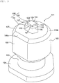
FIG. 1 is a perspective view illustrating a stud pin according to a first embodiment of the present invention; -
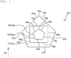
FIG. 2 is a plan view illustrating a shaft of the stud pin according to the first embodiment; -
FIG. 3 is a partial side view of the stud pin according to the first embodiment, which was taken from the direction of an arrow III ofFIG. 1 ; -
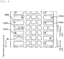
FIG. 4 is a developed view of a tread portion of a pneumatic tire on which the stud pins according to the first embodiment are mounted; -
FIG. 5A is a plan view illustrating a shaft of a stud pin according to a second embodiment; -
FIG. 5B is a partial side view of the stud pin according to the second embodiment, which was taken in the same manner asFIG. 3 ; -
FIG. 6A is a plan view illustrating a shaft of a stud pin according to a third embodiment; -
FIG. 6B is a partial side view of the stud pin according to the third embodiment, which was taken in the same manner asFIG. 3 ; -
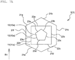
FIG. 7A is a plan view illustrating a shaft of a stud pin according to a fourth embodiment; -
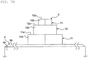
FIG. 7B is a partial side view of the stud pin according to the fourth embodiment, which was taken in the same manner asFIG. 3 ; -
FIG. 8 is a partial perspective view illustrating a stud pin according to Comparative Example; -
FIG. 9 is a perspective view illustrating a stud pin according to a fifth embodiment; -
FIG. 10 is a front view of the stud pin illustrated inFIG. 1 ; -
FIG. 11 is a plan view of the stud pin illustrated inFIG. 1 ; -
FIG. 12 is a cross-sectional view of one of the pin holes illustrated inFIG. 4 ; -
FIG. 13 is a plan view illustrating a shaft according to Example 2; -
FIG. 14 is a plan view illustrating a shaft according to Example 3; -
FIG. 15 is a plan view illustrating a shaft according to Example 4; -
FIG. 16 is a plan view illustrating a shaft according to Example 5; -
FIG. 17 is a plan view illustrating a shaft according to Example 6; -
FIG. 18 is a plan view illustrating a shaft according to Example 7; -
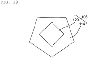
FIG. 19 is a plan view illustrating a shaft according to Example 8; -
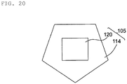
FIG. 20 is a plan view illustrating a shaft according to Example 9; -
FIG. 21 is a plan view illustrating a shaft according to Comparative Example 1; -
FIG. 22 is a plan view illustrating a stud pin according to another embodiment; -
FIG. 23 is a plan view illustrating a stud pin according to yet another embodiment; -
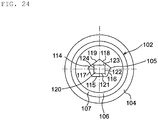
FIG. 24 is a plan view illustrating a stud pin according to yet another embodiment; and -
FIG. 25 is a plan view illustrating a stud pin according to yet another embodiment. - Embodiments of the present invention will now be described referring to the attached drawings.
- Referring to
FIGs. 1 to 3 , astud pin 1 of this embodiment as a whole has a shape that extends along its axis AX. In the following descriptions, the term "plan view" may be hereinafter used for the shape of thestud pin 1 viewed from its tip side along the axis AX. - The
stud pin 1 comprises: abase 2 on the bottom-most side; ashank 3 protruding from thebase 2; and abody 4 arranged on the tip of theshank 3. Thestud pin 1 further comprises ashaft 5 protruding from thebody 4. - In this embodiment, the
base 2 is substantially disk-shaped, and thebody 4 is substantially cylindrical. Theshank 3 has a substantially short cylindrical shape having a smaller diameter than thebase 2 and thebody 4. Further, thebase 2, theshank 3 and thebody 4 constitute an integrated structure and are made of aluminum or an aluminum alloy. Other structures and other materials can be employed for all of thebase 2, theshank 3 and thebody 4. - The
body 4 comprises anend surface 4a and aside surface 4b. In this embodiment, theend surface 4a is substantially a flat surface that extends perpendicular to the axis AX. Theend surface 4a may be inclined with respect to the axis AX and may be a non-flat surface. Theshaft 5 protrudes from theend surface 4a of thebody 4 in the direction along the axis AX. The outline or outer shape of theshaft 5 in a plan view fits inside a region bounded by the outer shape of theend surface 4a of thebody 4 in the plan view. In other words, the area of the outer shape of theshaft 5 in a plan view is smaller than the area of the outer shape of theend surface 4a of thebody 4 in the plan view. For example, the area of the former can be set at 10 to 45% of the area of the latter. - In this embodiment, the material of the
shaft 5 is tungsten. Theshaft 5 is a separate component from thebase 2, theshank 3 and thebody 4, and is engaged and thereby fixed with thebody 4. As for theshaft 5, other material can be employed. Theshaft 5 and thebody 4 may have an integrated structure as well. - Referring to
FIG. 4 in combination, thestud pin 1 is used by being mounted intopin holes 6b that are formed on atread portion 6a of a pneumatic tire (stud tire) 6. Thebase 2 and theshank 3 are entirely housed in eachpin hole 6b. Thebody 4 is housed in eachpin hole 6b with itsend surface 4a and theshaft 5 being exposed on thetread portion 6. - The
shaft 5 has a multi-stepped structure comprising plural steps. In this embodiment, theshaft 5 comprises three steps, namely afirst step 11, asecond step 12 and athird step 13. The first to thethird steps shaft 5 compriseend surfaces side surfaces first step 11, protrudes from theend surface 4a of thebody 4. Further, the intermediate step, namely thesecond step 12, protrudes from theend surface 11a of thefirst step 11. Still further, the endmost step, namely thethird step 13, protrudes from theend surface 12a of thesecond step 12. Theshaft 5 may have four or more steps. - The total height of the shaft 5 (in this embodiment, the height from the
end surface 4a of thebody 4 to theend surface 13a of the third step 13) can be set at, for example, 0.5 mm to 3 mm. In addition, the ratio of a sum of the heights of the steps other than the first step 11 (in this embodiment, a sum of the heights of the second and thethird steps 12 and 13) with respect to the total height of the shaft can be set at, for example, 10% to 90%. - In the first to the
third steps shaft 5, the end surfaces 11a, 12a and 13a in a plan view have larger outer shapes toward the side of thebody 4, namely the base-end side. Conversely, in the first to thethird steps shaft 5, the end surfaces 11a, 12a and 13a in a plan view have smaller outer shapes toward the tip side. Accordingly, theshaft 5 as a whole constitutes a pointed protrusion that protrudes in a stepped manner from theend surface 4a of thebody 4. - In this embodiment, the end surfaces 11a, 11b and 11c of the first to the
third steps - As most clearly illustrated in
FIG. 2 , the outer shapes of the end surfaces 11a, 12a and 13a of the first to thethird steps first step 11 whoseend surface 11a is pentagonal, five sides andedge components end surface 11a and theside surface 11b. Further, in thesecond step 12 whoseend surface 12a is quadrangular, four sides andedge components end surface 12a and theside surface 12b. Moreover, in thethird step 13 whoseend surface 13a is pentagonal, five sides andedge components end surface 13a and theside surface 13b. In this embodiment, theedge components 21a to 21e, 22a to 22d and 23a to 23e are linear. However, theseedge components 21a to 21e, 22a to 22d and 23a to 23e are not required to be linear in a geometrically strict sense and may be curved or tortuous to a certain extent as long as a scratching effect on icy and snowy road surfaces is attained. In addition, theseedge components 21a to 21e, 22a to 22d and 23a to 23e may be chamfered as long as a scratching effect on icy and snowy road surfaces is attained. - As described above, the
end surface 11a of thefirst step 11 has a pentagonal planar shape, and theend surface 12a of thesecond step 12 has a quadrangular planar shape. In other words, thefirst step 11 and thesecond step 12 of theshaft 5 are different in terms of the outer shapes of theirend surfaces edge components 21a to 21d of thefirst step 11 and theedge components 22a to 22d of thesecond step 12 have different orientations in a plan view. More specifically, in a plan view, none of theedge components 22a to 22d of thesecond step 12 is parallel to any of theedge components 21a to 21e of thefirst step 11. In other words, as conceptually illustrated with a symbol E inFIG. 1 , theshaft 5 has edge components oriented in multiple directions, and these edge components act in the multiple directions. As a result, the driving performance on icy and snowy road surfaces is improved. - The
first step 11 has fiveedge components 21a to 21e, and thesecond step 12 has fouredge components 22a to 22d. In addition, theend surface 12a of thesecond step 12 is smaller than theend surface 11a of thefirst step 11. Generally speaking, when the end surfaces of steps have the same size, the larger the number of edge components, the shorter is the lengths of the individual edge components. Accordingly, by setting the number of the edge components of thefirst step 11 having the relativelylarge end surface 11a to be relatively large, theedge components 21a to 21e can be ensured in multiple directions while securing the lengths of theindividual edge components 21a to 21e. Moreover, by setting the number of the edge components of thesecond step 12 having the relativelysmall end surface 12a to be relatively small, theedge components 22a to 22d can be ensured in directions different from the directions of theedge components 21a to 21e of thefirst step 11 while securing the lengths of theindividual edge components 22a to 22d. As a result, the driving performance on icy and snowy road surfaces is further improved as compared to a case where the outer shape of theend surface 11a of thefirst step 11 and that of theend surface 12a of thesecond step 12 are simply different. - As described above, the
end surface 13a of thethird step 13, which is the endmost step, is pentagonal and has fiveedge components 23a to 23e. Further, theend surface 12a of thesecond step 12, which is the second endmost step, is quadrangular and has fouredge components 22a to 22d. In other words, the number of theedge components 23a to 23e of thethird step 13, which is the endmost step, is larger than the number of theedge components 22a to 22d of thesecond step 12, which is the second endmost step. - With regard to the first to the
third steps 11 to 13, each step exerts a higher piercing effect on icy and snowy road surfaces as the number of the edge components is increases. Moreover, thethird step 13, which is the endmost step, exerts a higher piercing effect on icy and snowy road surfaces as compared to the first and thesecond steps third step 13, which is the endmost step, to be larger than the number of the edge components of thesecond step 12, the piercing effect of theshaft 5 on icy and snowy road surfaces can be effectively improved, and the driving performance on icy and snowy road surfaces can thereby be improved. - Generally speaking, when the total number of steps of a shaft is an odd number, by setting the number of edge components of an (N + 1)th step (wherein, N is a natural number), which is an odd-numbered step, to be larger than the number of edge components of an Nth step, the endmost step is allowed to have a larger number of edge components than the second endmost step. Similarly, when the total number of steps of a shaft is an even number, by setting the number of edge components of an (N + 1)th step (wherein, N is a natural number), which is an even-numbered step, to be larger than the number of edge components of an Nth step, the endmost step is allowed to have a larger number of edge components than the second endmost step.
- When the
stud pin 1 is mounted on thetread portion 6a such that the rotational direction of thepneumatic tire 6 is oriented in the direction indicated by an arrow R1 ofFIG. 2 with respect to the shape of theshaft 5 in a plan view, a pointed part 31g, which is formed at the junction of theedge components first step 11, and apointed part 33g, which is formed at the junction of theedge components third step 13, are positioned on the leading side. Therefore, the piercing effect of these pointedparts 31g and 33g on icy and snowy road surfaces effectively contributes to an improvement of the drive torque. Further, in this case, theedge component 21d of thefirst step 11 and theedge component 22c of thesecond step 12 are positioned on the trailing side. Therefore, the scratching effect of theseedge components - With regard to the second to the fourth embodiments described below, structures and functions that are not particularly mentioned are the same as in the first embodiment. Further, in the drawings relating to these embodiments, the same symbols are assigned to those elements that are identical or similar to the corresponding elements of the first embodiment.
- In the
stud pin 1 according to the second embodiment that is illustrated inFIGs. 5A and5B , the outer shapes of the end surfaces 11a to 11c of the first to thethird steps 11 to 13 in a plan view are pentagonal, quadrangular and hexagonal, respectively. Thefirst step 11 comprises fiveedge components 21a to 21e, and thesecond step 12 comprises fouredge components 22a to 22d. Further, thethird step 13 comprises sixedge components 23a to 23f. - The
first step 11 and thesecond step 12 have different outer shapes in a plan view, and the number of the edge components of thesecond step 12 is four, which is less than the number of the edge components of thefirst step 11 that is five. Moreover, the number of the edge components of thethird step 13, which is the endmost step, is six and thus larger than the number of the edge components of thesecond step 12, which is the second endmost step, of four. - In the
stud pin 1 according to the third embodiment that is illustrated inFIGs. 6A and6B , the outer shapes of the end surfaces 11a to 11c of the first to thethird steps 11 to 13 in a plan view are hexagonal, circular and quadrangular, respectively. Thefirst step 11 comprises sixedge components 21a to 21f, and the number of the edge components of thesecond step 12 that is circular can be regarded as infinity. Further, thethird step 13 comprises fouredge components 23a to 23d. - The outer shape of the
first step 11 in a plan view is hexagonal, which is different from the outer shape of thesecond step 12 in a plan view that is circular. - In the
stud pin 1 according to the fourth embodiment that is illustrated inFIGs. 7A and7B , the outer shapes of the end surfaces 11a to 11c of the first to thethird steps 11 to 13 in a plan view are hexagonal, quadrangular and pentagonal, respectively. Thefirst step 11 comprises sixedge components 21a to 21f, and thesecond step 12 comprises fouredge components 22a to 22d. Further, thethird step 13 comprises fiveedge components 23a to 23e. - The
first step 11 and thesecond step 12 have different outer shapes in a plan view, and the number of the edge components of thesecond step 12 is four, which is less than the number of the edge components of thefirst step 11 that is six. Moreover, the number of the edge components of thethird step 13, which is the endmost step, is five and thus larger than the number of the edge components of thesecond step 12, which is the second endmost step, of four. - As shown in Table 1 below, the stud pins of Comparative Example and the first to the fourth embodiments (which were all brand new) were tested to evaluate the drive performance, the braking performance and the turning performance.
- As test tires, tires having a size of 195/65R15 and an air pressure Fr/Re of 220/220 (kPa) were used. In this evaluation test, the test tires were mounted on a test vehicle (1,500 cc, 4WD mid-size sedan), and this test vehicle was driven on an icy road surface. For the evaluation of the edge performance, the first to the fourth embodiments were each evaluated as an index, taking the edge performance of Comparative Example as 100. The drive performance was evaluated in terms of the time required for the test vehicle to reach 30 m after starting from a stopped state on the icy road surface. The braking performance was evaluated in terms of the braking distance when a braking force was applied by ABS (Antilock Brake System) at a speed of 40 km/h. The turning performance was evaluated in terms of the turning radius when a turn was made at the same speed of 40 km/h.
- As illustrated in
FIG. 8 , thestud pin 1 of Comparative Example has ashaft 5 constituted by a single cylinder, not by a multi-stepped structure. For all of Comparative Example and the first to the fourth embodiments, the stud pins 1 were mounted on the test tire such that the tire rotational direction was oriented in the direction indicated by the arrow R1 in the drawings.[Table 1] Comparative Example First embodiment ( FIGs. 2 and3 )Second embodiment ( FIGs. 5A and5B )Shaft shape Cylindrical First step: pentagonal First step: pentagonal Second step: quadrangular Second step: quadrangular Third step: hexagonal Third step: hexagonal Drive performance 100 106 105 Braking performance 100 108 107 Turning performance 100 104 106 Third embodiment ( FIGs. 6A and6B )Fourth embodiment ( FIGs. 7A and7B )Shaft shape First step: hexagonal First step: hexagonal Second step: circular Second step: quadrangular Third step: square Third step: pentagonal Drive performance 105 106 Braking performance 105 106 Turning performance 107 108 - The first to the fourth embodiments, in which the
first step 11 and thesecond step 12 had different outer shapes in a plan view, exerted superior performance than Comparative Example for all of the drive performance, the braking performance and the turning performance. -
FIGs. 9 and10 illustrate astud pin 101 according to the fifth embodiment. Thestud pin 101 is formed by, for example, molding aluminum, an aluminum alloy or the like, and thestud pin 101 comprises: abody 102; ashank 103 extending on a lower side of thebody 102; a base 104 further extending on a lower side of theshank 103; and ashaft 105 arranged on a center part of the upper surface of thebody 102. - The
body 102 is substantially cylindrical; however, aside surface 106, which is parallel to the center axis, is formed on a part of the outer circumferential surface. By this, at least on an upper-end periphery of thebody 102, a bodyside edge component 108a which is parallel to a straight line perpendicular to the axis (see the symbol AX inFIG. 1 ) in a plan view and an arc-shapedpart 108b which has a circular arc shape in a plan view are formed. - The upper-surface periphery of the
body 102 is constituted by a tapered surface 7. Thetapered surface 107 is a region that initially comes into contact with the road surface when a pneumatic tire (stud tire) on which thestud pin 101 is mounted is driven on a road. In this embodiment, thetapered surface 107, which is formed on the bodyside edge component 108a, is the region that initially collides with the road surface. Accordingly, thetapered surface 107 makes a surface contact when the bodyside edge component 108a collides with the road surface. It is noted here, however, that the term "taperedsurface 107" used herein is construed to encompass a slightly curved surface shape as long as a pointed part thereof can be prevented from colliding with the road surface. Further, the arc-shapedpart 108b encompasses not only a circular arc but also a part of a polygonal shape connected by plural line segments. It is noted here that the length of each line segment is shorter than the bodyside edge component 108a. - Moreover, in the
body 102, a diameter L1 of the cylindrical portion and a length L2 of the bodyside edge component 108a in a plan view are set such they satisfy arelationship 1/4 < L2/L1 < 3/4. At an L2/L1 value of 1/4 or less, thebody 102 has an excessively high partial contact pressure upon contact with the ground, whereas at an L2/L1 value of 3/4 or larger, thebody 102 is likely to be damaged upon contact with the ground. It is noted here that, as illustrated inFIG. 22 , thebody 102 may have a cylindrical shape, namely a circular shape without the bodyside edge component 108a in a plan view. - As illustrated in
FIG. 11 , thebase 104 is formed in a longitudinally elongated shape whose maximum length "a" in the longitudinal direction and maximum length "b" in the transverse direction satisfy a > b in a plan view. On one end of the longitudinal direction of thebase 104, alinear part 109 parallel to theside surface 106 of thebody 102 is formed. Further, in thebase 104, a protrudingpart 111, which comprises twoinclined parts 110 on the opposite side of thelinear part 109 and protrudes in a triangular shape, is formed. In this embodiment, the protrudingpart 111 in the drawing is bilaterally symmetrical about a longitudinal center line. In addition, an angle formed by eachinclined part 110 with the longitudinal center line is set to be smaller than 90°. This angle is particularly preferably 45°. Thebase 104 comprises two arc-shapedparts 112 which connect thelinear part 109 and the respectiveinclined parts 110. Moreover, thelinear part 109, theinclined parts 110 and the arc-shapedparts 112 are connected such that no edge component is formed. On the lower surface of the outer periphery of thebase 104, atapered surface 113 is formed. - The shape of the
base 104 is not restricted to the one illustrated inFIG. 11 , and the base 104 may take various forms such as a circular shape and a polygonal shape, as long as thebase 104 extends to the outer side than thebody 102 in a plan view.FIG. 23 illustrates an example in which thebase 104 is circular in a plan view. As illustrated inFIG. 24 , thebody 102 can also be circular in a plan view to make both thebase 104 and thebody 102 circular in a plan view. However, as described above, by forming the base 104 in a heterogeneous shape, dislodgement of thestud pin 101 from thepin holes 6b (seeFIG. 4 ) during driving on a road can be effectively inhibited in a state where an increase in weight is suppressed and thestud pin 101 is mounted on a tire. - The
shaft 105 comprises afirst step 114 which has an odd-numbered polygonal shape in a plan view (a pentagonal shape in this embodiment). Afirst edge component 115, which includes one side (edge component) of thefirst step 114, extends in parallel to theside surface 6 of thebody 102 in a plan view. The length of thefirst edge component 115 is set to be shorter than the length of the bodyside edge component 108a. Asecond edge component 116 and athird edge component 117, which are adjacent to thefirst edge component 115 on the respective sides thereof, face the arc-shaped part of thebase 104. Further, afourth edge component 118 adjacent to thesecond edge component 116 and afifth edge component 119 adjacent to thethird edge component 117 face the respectiveinclined parts 110 of thebase 104. - On the upper surface of the
first step 114, asecond step 120 is formed. Thesecond step 120 has a rectangular shape in a plan view, and a sixth edge component 21, which is one of the long sides of the rectangular shape, is parallel to thefirst edge component 115 of thefirst step 114. It is noted here that, in a plan view, other edge components of the second step 120 (aseventh edge component 122, aneighth edge component 123, and a ninth edge component 124) extend in different directions from the opposing edge components of thefirst step 114. - The
shaft 105 is arranged such that its axis is aligned with the axis of thebody 102. By this, a sufficient distance can be ensured between the outer periphery of thebody 102 and theshaft 105 in all directions. In addition, thesecond step 120 has a smaller number of edge components than thefirst step 114. Specifically, thefirst step 114 has five edge components, while thesecond step 120 has four edge components. Moreover, in this embodiment, the height of theshaft 105 is 0.5 mm to 2.5 mm. The reason for this is that theshaft 105 cannot sufficiently exert its functions at a height of less than 0.5 mm, and theshaft 105 contacts the ground before thebody 102 and is thus likely to be damaged at a height of greater than 2.5 mm. Furthermore, the height ratio of thesecond step 120 with respect to thefirst step 114 is set to be 10% to 80%. The edge effect of thesecond step 120 is insufficient when the height ratio is lower than 10%, and thefirst step 114 cannot sufficiently exert an edge effect when the height ratio is higher than 80%. - By configuring the
shaft 105 to have two steps in this manner, the total edge length can be increased, so that a sufficient edge effect can be exerted. In addition, since the edge components of the first and thesecond steps shaft 105 may be constituted by three or more steps as well. - As illustrated in
FIG. 4 , thestud pin 101 having the above-described constitution is mounted into thepin holes 6b formed on thetread portion 6a of thepneumatic tire 6. As illustrated inFIG. 12 , thepin holes 6b are each constituted by a small-diameter part 27 having the same inner diameter and a large-diameter part 28 on the tip thereof. An operation of mounting thestud pin 101 into eachpin hole 6b is automatically performed by a pin driving device (not illustrated). In this case, thebase 104 has the above-described longitudinally elongated heterogeneous shape, not a point-symmetrical shape such as a circular shape; therefore, the orientation of thestud pin 101 can be easily understood and thestud pin 101 can thus be accurately mounted into eachpin hole 6b. In this embodiment, theside surface 106 of the body 102 (the first side surface of the shaft 105) is positioned on the tire trailing side such that it extends in the tire widthwise direction perpendicular to the tire circumferential direction. In this state, a part of thestud pin 101 above the upper end (tapered surface 7) of thebody 102 is exposed from the surface of thetread portion 6a. - According to the
stud pin 101 mounted on a tire in this manner, during driving, the bodyside edge component 108a constituting an upper-end part of thebody 102 initially collides with the road surface. The bodyside edge component 108a has sufficient length and area. Therefore, even when the bodyside edge component 108a collides with the road surface, the impact force applied per unit area of the road surface can be reduced. As a result, problems such as road surface cracking can be avoided even when driving on a dry road surface. Further, when driving on a frozen road surface (icy surface), the bodyside edge component 108a bites into the road surface to exert an excellent driving force. - The
shaft 105 subsequently collides with the road surface. In this case, a sufficient distance is secured between thebody 102 and theshaft 105. Therefore, theshaft 105 is prevented from colliding with the road surface before thebody 102. As a result, damage to theshaft 105 caused by collision with the road surface can be inhibited. - The
shaft 105 that collides with the road surface is constituted by two steps and, in a plan view, thefirst step 114 and thesecond step 120 have different directions of pointed vertexes except at one spot. Therefore, the edge effect of theshaft 105 can be sufficiently exerted. In other words, in straight driving, thefourth edge component 118 and thefifth edge component 119 of thefirst step 114 and the vertex where these edge components intersect with each other, as well as theeighth edge component 123 of thesecond step 120, act on the road surface (icy surface). Further, when cornering a curve, thesecond edge component 116 or thethird edge component 117 of thefirst step 114 and theseventh edge component 122 or theninth edge component 124 of thesecond step 120 inhibit skidding on the road surface. Moreover, when the brake is applied, thefirst edge component 115 of thefirst step 114 and the sixth edge component 21 of thesecond step 120 apply a braking force against the road surface. - In these processes, a force that causes the
stud pin 101 to fall out of the pin hole 26 acts on thestud pin 101 through thebody 102 and theshaft 105. Thestud pin 101 comprises theshaft 105 having a smaller diameter than thebody 102 and the base 104 having a larger diameter than thebody 102 connected to theshaft 5, so that dislodgement of thestud pin 101 is effectively inhibited. - The edge performance was tested for the stud pin of Comparative Example, whose
shaft 105 had the plan-view shape illustrated inFIG. 21 , as well as the stud pins of Examples 1 to 9 that are illustrated inFIGs. 11 and13 to 20 (see Table 2). As test tires, tires having a size of 195/65R15 and an air pressure Fr/Re of 220/220 (kPa) were used. In the test, the test tires were mounted on a test vehicle (1,500 cc, 4WD mid-size sedan), and this test vehicle was driven on an icy road surface to evaluate the edge performance (drive performance, braking performance and turning (cornering) performance). For the evaluation of the edge performance, Examples 1 to 9 were each evaluated as an index, taking the edge performance of Comparative Example 1 as 100. The drive performance was evaluated in terms of the elapsed time required for the driving distance to reach 30 m after starting from a stopped state on the icy road surface. The braking performance was evaluated in terms of the braking distance when a braking force was applied by ABS (Antilock Brake System) at a speed of 40 km/h. The turning performance was evaluated in terms of the turning radius when a turn was made at the same speed of 40 km/h. - The
shaft 105 protruding from a center part of the upper surface of thecylindrical body 102 had the below-described plan-view shapes. It is noted here that the upper side indicates the traveling direction, namely the tire leading side, in all of the drawings. - In Comparative Example, the
shaft 105 has a circular shape with only one step as illustrated inFIG. 14 . - Example 1 is as described in the fifth embodiment illustrated in
FIG. 10 . - In Example 2, as illustrated in
FIG. 13 , thefirst step 114 and thesecond step 120 are formed in a hexagonal shape and a pentagonal shape, respectively. Their vertexes face each other at one spot. - In Example 3, as illustrated in
FIG. 14 , thefirst step 114 and thesecond step 120 are formed in a heptagonal shape and a pentagonal shape, respectively. The shape of thefirst step 114 has a depression at one spot. The vertex positioned in the depression faces one of the vertexes of the second step, and the sides positioned on the opposite side thereof are parallel to each other. - In Example 4, as illustrated in
FIG. 15 , thefirst step 114 and thesecond step 120 are formed in a heptagonal shape and a hexagonal shape, respectively. The six sides of thefirst step 114 and the sides of thesecond step 120 are arranged in parallel to each other. - In Example 5, as illustrated in
FIG. 16 , thefirst step 114 and thesecond step 120 are formed in a star shape and a hexagonal shape, respectively. - In Example 6, as illustrated in
FIG. 17 , thefirst step 114 and thesecond step 120 are formed in a pentagonal shape and a trapezoidal shape, respectively. - In Example 7, as illustrated in
FIG. 18 , thefirst step 114 and thesecond step 120 are formed in a heptagonal shape and a triangular shape, respectively. In thefirst step 114, the center part of one side of a trapezoid (the upper side in the drawing) protrudes in a triangular shape, forming a heptagon. - In Example 8, as illustrated in
FIG. 19 , thefirst step 114 and thesecond step 120 are formed in a pentagonal shape and a quadrangular shape, respectively. Thesecond step 120 is arranged such that one of its diagonal lines is aligned with the traveling direction. - In Example 9, as illustrated in
FIG. 20 , thefirst step 114 and thesecond step 120 are formed in a pentagonal shape and a quadrangular shape, respectively. Example 9 and Example 8 are different in terms of the orientation of thesecond step 120. In Example 9, two parallel sides of the second step are arranged perpendicular to the traveling direction.[Table 2] Comparative Example Example 1 Example 2 Shaft shape Circular First step: pentagonal First step: hexagonal Second step: quadrangular Second step: pentagonal Drive performance 100 103 104 Braking performance 100 105 103 Turning performance 100 103 105 Example 3 Example 4 Example 5 Shaft cross-sectional shape First step: heptagonal First step: heptagonal First step: star shape Second step: pentagonal Second step: hexagonal Second step: hexagonal Drive performance 105 104 104 Braking performance 104 102 104 Turning performance 106 105 107 Example 6 Example 7 Example 8 Shaft shape First step: pentagonal First step: heptagonal First step: pentagonal Second step: trapezoidal Second step: triangular Second step: quadrangular Drive performance 103 104 103 Braking performance 106 106 104 Turning performance 102 104 104 Example 9 First step: pentagonal Shaft shape Second step: quadrangular Drive performance 101 Braking performance 105 Turning performance 102 - As shown above, in Examples 1 to 9, excellent effects were exerted by the respective edge components in all of the items of the edge effect. These edge effects were attained because the two-step configuration enabled to freely set the directions of the edge components and to increase the lengths of the edge components.
- In the fifth embodiment, the body
side edge component 108a was arranged on the tire trailing side such that it extends perpendicular to the tire circumferential direction along the tire widthwise direction; however, the bodyside edge component 108a may be arranged on the tire leading side as well. This makes it easier for the bodyside edge component 108a to exert a braking force. - In the fifth embodiment, the body
side edge component 108a of thebody 102 and thefirst edge component 115 of theshaft 105 were both arranged on the lower side with respect to a dash-dotted line extending in the lateral direction; however, they can also be arranged on the opposite sides. InFIG. 25 , theshaft 105 is rotated by 180° so as to arrange the bodyside edge component 108a and thefirst edge component 115 of theshaft 105 on the lower side and the upper side, respectively, with respect to a straight line extending in the lateral direction. In this case, the bodyside edge component 108a can be arranged on the tire leading side perpendicular to the tire circumferential direction, and thefirst edge component 115 of theshaft 105 can be arranged on the tire trailing side. According to this constitution, braking performance can be exerted by the bodyside edge component 108a, and traction performance can be exerted by thefirst edge component 115 of theshaft 105. -
- 1, 101:
- stud pin
- 2:
- base
- 3:
- shank
- 4:
- body
- 4a:
- end surface
- 4b:
- side surface
- 5:
- shaft
- 11:
- first step
- 11a:
- end surface
- 11b:
- side surface
- 12:
- second step
- 12a:
- end surface
- 12b:
- side surface
- 13:
- third step
- 13a:
- end surface
- 13b:
- side surface
- 6:
- pneumatic tire
- 6a:
- tread portion
- 6b:
- pin hole
- 21a, 21b, 21c, 21d, 21e, 21f:
- edge component
- 22a, 22b, 22c, 22d, 22e, 22f:
- edge component
- 23a, 23b, 23c, 23d, 23e, 23f:
- edge component
- 31g, 33g:
- pointed part
- 101:
- stud pin
- 102:
- body
- 103:
- shank
- 104:
- base
- 105:
- shaft
- 106:
- side surface
- 107:
- tapered surface
- 108a:
- body side edge component (edge component)
- 108b:
- arc-shaped part
- 109:
- linear part
- 110:
- inclined part
- 111:
- protruding part
- 112:
- arc-shaped part
- 113:
- tapered surface
- 114:
- first step
- 115:
- first edge component
- 116:
- second edge component
- 117:
- third edge component
- 118:
- fourth edge component
- 119:
- fifth edge component
- 120:
- second step
- 121:
- sixth edge component
- 122:
- seventh edge component
- 123:
- eighth edge component
- 124:
- ninth edge component
- 125:
- tread portion
- 126:
- pin hole
- 127:
- small-diameter part
- 128:
- large-diameter part
Claims (13)
- A stud pin comprising:a body; anda shaft protruding from the body, whereinthe shaft has a multi-stepped structure that comprises at least a first step protruding from the body and a second step protruding from the first step, andan outer shape of the first step in a plan view and that of the second step in a plan view are different.
- The stud pin according to claim 1, wherein the shaft further comprises a third step protruding from the second step.
- The stud pin according to claim 2, wherein a number of edge components of the second step is less than a number of edge components of the first step.
- The stud pin according to claim 2 or 3, wherein a number of edge components of an endmost step is larger than a number of edge components of a second endmost step.
- The stud pin according to any one of claims 2 to 4, wherein
a total number of the steps of the shaft is an odd number, and
the number of the edge components of an (N + 1)th step, which is an odd-numbered step, is larger than the number of the edge components of an Nth step. - The stud pin according to any one of claims 2 to 4, wherein
a total number of the steps of the shaft is an even number, and
the number of the edge components of an (N + 1)th step, which is an even-numbered step, is larger than the number of the edge components of an Nth step. - The stud pin according to claim 1, wherein the outer shape of the first step in a plan view and that of the second step in a plan view are dissimilar.
- The stud pin according to claim 7, wherein at least either of the outer shape of the first step in a plan view and the outer shape of the second step in a plan view is polygonal.
- The stud pin according to claim 7 or 8, wherein the number of the edge components of the first step is less than the number of the edge components of the second step.
- The stud pin according to any one of claims 7 to 9, wherein the protruding dimension of the first step from the body is larger than the protruding dimension of the second step from the first step.
- A stud tire comprising:the stud pin according to any one of claims 1 to 10; andpin holes which are formed on a tread portion and in which the stud pin is mounted.
- A stud tire comprising:the stud pin according to any one of claims 7 to 10; andpin holes which are formed on a tread portion and in which the stud pin is mounted,wherein the stud pin is arranged such that the edge components of the body are perpendicular to the tire circumferential direction on a tire trailing side.
- A stud tire comprising:the stud pin according to any one of claims 7 to 10; andpin holes which are formed on a tread portion and in which the stud pin is mounted,wherein the stud pin is arranged such that the edge components of the body are perpendicular to the tire circumferential direction on a tire leading side.
Applications Claiming Priority (3)
| Application Number | Priority Date | Filing Date | Title |
|---|---|---|---|
| JP2016209192A JP6688202B2 (en) | 2016-10-26 | 2016-10-26 | Stud tire with stud pins |
| JP2016209208A JP6688203B2 (en) | 2016-10-26 | 2016-10-26 | Stud pin and pneumatic tire with stud pin |
| PCT/JP2017/021230 WO2018078934A1 (en) | 2016-10-26 | 2017-06-08 | Stud pin and pneumatic tire provided with stud pin |
Publications (2)
| Publication Number | Publication Date |
|---|---|
| EP3533626A1 true EP3533626A1 (en) | 2019-09-04 |
| EP3533626A4 EP3533626A4 (en) | 2020-06-03 |
Family
ID=62024620
Family Applications (1)
| Application Number | Title | Priority Date | Filing Date |
|---|---|---|---|
| EP17863897.9A Withdrawn EP3533626A4 (en) | 2016-10-26 | 2017-06-08 | Stud pin and pneumatic tire provided with stud pin |
Country Status (4)
| Country | Link |
|---|---|
| EP (1) | EP3533626A4 (en) |
| CA (1) | CA3040239C (en) |
| RU (1) | RU2721442C1 (en) |
| WO (1) | WO2018078934A1 (en) |
Family Cites Families (6)
| Publication number | Priority date | Publication date | Assignee | Title |
|---|---|---|---|---|
| JPS5836708A (en) * | 1981-08-26 | 1983-03-03 | Toshio Takayama | Spike pin for car tire |
| JPS5981204A (en) * | 1982-10-30 | 1984-05-10 | Kida Nousan Kk | Nonskid device for automobile tubeless tire |
| JPS59133301U (en) * | 1983-02-28 | 1984-09-06 | 横浜ゴム株式会社 | tire spikes |
| FI119183B (en) * | 2005-12-16 | 2008-08-29 | Scason Oy | Double pin for a stud in a studded deck |
| JP2008207743A (en) * | 2007-02-27 | 2008-09-11 | Yokohama Rubber Co Ltd:The | Stud tire and its manufacturing method |
| JP6087247B2 (en) * | 2013-09-18 | 2017-03-01 | 東洋ゴム工業株式会社 | Tire stud and pneumatic stud tire |
-
2017
- 2017-06-08 EP EP17863897.9A patent/EP3533626A4/en not_active Withdrawn
- 2017-06-08 CA CA3040239A patent/CA3040239C/en not_active Expired - Fee Related
- 2017-06-08 WO PCT/JP2017/021230 patent/WO2018078934A1/en not_active Ceased
- 2017-06-08 RU RU2019111418A patent/RU2721442C1/en active
Also Published As
| Publication number | Publication date |
|---|---|
| CA3040239A1 (en) | 2018-05-03 |
| EP3533626A4 (en) | 2020-06-03 |
| CA3040239C (en) | 2021-06-01 |
| RU2721442C1 (en) | 2020-05-19 |
| WO2018078934A1 (en) | 2018-05-03 |
Similar Documents
| Publication | Publication Date | Title |
|---|---|---|
| JP2016215962A (en) | Tire for winter | |
| CA3040244C (en) | Stud pin and pneumatic tire provided with stud pin | |
| CA3040239C (en) | Stud pin and pneumatic tire provided with stud pin | |
| EP3533629A1 (en) | Stud pin and pneumatic tire provided with stud pin | |
| EP3533627B1 (en) | Stud pin and pneumatic tire provided with stud pin | |
| EP3533628A1 (en) | Stud pin, and pneumatic tire provided with stud pin | |
| EP3533632A1 (en) | Stud pin, and pneumatic tire provided with stud pin | |
| EP3533630A1 (en) | Stud pin and pneumatic tire provided with stud pin | |
| CA3040283C (en) | Stud pin and pneumatic tire provided with stud pin | |
| JP6688202B2 (en) | Stud tire with stud pins | |
| JP6688203B2 (en) | Stud pin and pneumatic tire with stud pin | |
| WO2018078932A1 (en) | Stud pin and pneumatic tire provided with stud pin | |
| WO2018078933A1 (en) | Stud pin and pneumatic tire provided with stud pin | |
| JP2018069820A (en) | Stud pins and pneumatic tires with stud pins |
Legal Events
| Date | Code | Title | Description |
|---|---|---|---|
| STAA | Information on the status of an ep patent application or granted ep patent |
Free format text: STATUS: THE INTERNATIONAL PUBLICATION HAS BEEN MADE |
|
| PUAI | Public reference made under article 153(3) epc to a published international application that has entered the european phase |
Free format text: ORIGINAL CODE: 0009012 |
|
| STAA | Information on the status of an ep patent application or granted ep patent |
Free format text: STATUS: REQUEST FOR EXAMINATION WAS MADE |
|
| 17P | Request for examination filed |
Effective date: 20190416 |
|
| AK | Designated contracting states |
Kind code of ref document: A1 Designated state(s): AL AT BE BG CH CY CZ DE DK EE ES FI FR GB GR HR HU IE IS IT LI LT LU LV MC MK MT NL NO PL PT RO RS SE SI SK SM TR |
|
| AX | Request for extension of the european patent |
Extension state: BA ME |
|
| DAV | Request for validation of the european patent (deleted) | ||
| DAX | Request for extension of the european patent (deleted) | ||
| A4 | Supplementary search report drawn up and despatched |
Effective date: 20200506 |
|
| RIC1 | Information provided on ipc code assigned before grant |
Ipc: B60C 11/16 20060101AFI20200428BHEP |
|
| STAA | Information on the status of an ep patent application or granted ep patent |
Free format text: STATUS: EXAMINATION IS IN PROGRESS |
|
| 17Q | First examination report despatched |
Effective date: 20210310 |
|
| STAA | Information on the status of an ep patent application or granted ep patent |
Free format text: STATUS: THE APPLICATION HAS BEEN WITHDRAWN |
|
| 18W | Application withdrawn |
Effective date: 20210602 |