EP3533625A1 - Stud pin and pneumatic tire provided with stud pin - Google Patents
Stud pin and pneumatic tire provided with stud pin Download PDFInfo
- Publication number
- EP3533625A1 EP3533625A1 EP17863426.7A EP17863426A EP3533625A1 EP 3533625 A1 EP3533625 A1 EP 3533625A1 EP 17863426 A EP17863426 A EP 17863426A EP 3533625 A1 EP3533625 A1 EP 3533625A1
- Authority
- EP
- European Patent Office
- Prior art keywords
- edge components
- hole
- shaft
- stud pin
- view
- Prior art date
- Legal status (The legal status is an assumption and is not a legal conclusion. Google has not performed a legal analysis and makes no representation as to the accuracy of the status listed.)
- Withdrawn
Links
- 230000000052 comparative effect Effects 0.000 description 11
- 230000000694 effects Effects 0.000 description 8
- 238000005299 abrasion Methods 0.000 description 5
- 230000002393 scratching effect Effects 0.000 description 5
- 230000005484 gravity Effects 0.000 description 4
- 238000011156 evaluation Methods 0.000 description 3
- 239000000463 material Substances 0.000 description 3
- 229910000838 Al alloy Inorganic materials 0.000 description 1
- XAGFODPZIPBFFR-UHFFFAOYSA-N aluminium Chemical compound [Al] XAGFODPZIPBFFR-UHFFFAOYSA-N 0.000 description 1
- 229910052782 aluminium Inorganic materials 0.000 description 1
- 238000006748 scratching Methods 0.000 description 1
- WFKWXMTUELFFGS-UHFFFAOYSA-N tungsten Chemical compound [W] WFKWXMTUELFFGS-UHFFFAOYSA-N 0.000 description 1
- 229910052721 tungsten Inorganic materials 0.000 description 1
- 239000010937 tungsten Substances 0.000 description 1
Images



Classifications
-
- B—PERFORMING OPERATIONS; TRANSPORTING
- B60—VEHICLES IN GENERAL
- B60C—VEHICLE TYRES; TYRE INFLATION; TYRE CHANGING; CONNECTING VALVES TO INFLATABLE ELASTIC BODIES IN GENERAL; DEVICES OR ARRANGEMENTS RELATED TO TYRES
- B60C11/00—Tyre tread bands; Tread patterns; Anti-skid inserts
- B60C11/14—Anti-skid inserts, e.g. vulcanised into the tread band
- B60C11/16—Anti-skid inserts, e.g. vulcanised into the tread band of plug form, e.g. made from metal, textile
- B60C11/1675—Anti-skid inserts, e.g. vulcanised into the tread band of plug form, e.g. made from metal, textile with special shape of the plug- tip
-
- B—PERFORMING OPERATIONS; TRANSPORTING
- B60—VEHICLES IN GENERAL
- B60C—VEHICLE TYRES; TYRE INFLATION; TYRE CHANGING; CONNECTING VALVES TO INFLATABLE ELASTIC BODIES IN GENERAL; DEVICES OR ARRANGEMENTS RELATED TO TYRES
- B60C11/00—Tyre tread bands; Tread patterns; Anti-skid inserts
- B60C11/14—Anti-skid inserts, e.g. vulcanised into the tread band
- B60C11/16—Anti-skid inserts, e.g. vulcanised into the tread band of plug form, e.g. made from metal, textile
Definitions
- the present invention relates to a stud pin, and a pneumatic tire comprising the stud pin.
- Stud pins for pneumatic tires improve the driving performance (including the drive performance, the braking performance, and the turning performance) of a vehicle, on which pneumatic tires and the stud pins are mounted, on icy and snowy road surfaces by scratching and piercing the icy and snowy road surfaces.
- the stud pin disclosed in Patent Literature 1 comprises a head or a body, and a pin or a shaft that protrudes from an end surface of the body.
- one side of the shaft has a discontinuous outline in which at least one tooth is defined.
- Patent Literature 1 WO 2014/122570 A1
- Patent Literature 1 Conventional stud pins including the one disclosed in Patent Literature 1 still have room for improvement in terms of the driving performance on icy and snowy road surfaces.
- An object of the present invention is to improve the driving performance exerted by a stud pin on icy and snowy road surfaces.
- One mode of the present invention provides a stud pin that comprises a body and a shaft protruding from the body, wherein the shaft has a multi-stepped structure that comprises plural steps including at least a first step protruding from the body and a second step protruding from the first step, and a hole is arranged on an end surface of an endmost step of the shaft.
- the margin of the hole arranged on the end surface of the endmost step constitutes edge components. Accordingly, by arranging the hole, the total number of edge components and the total length of edge line segments (edge component total length) can be increased. Therefore, by arranging the hole, the edge components are allowed to function more effectively, whereby the driving performance on icy and snowy road surfaces can be improved.
- the edge components of the shaft of the stud pin are allowed to function more effectively while securing the strength of the shaft, whereby the driving performance on icy and snowy road surfaces can be improved.
- An area A1 bounded by the outline of the end surface of the endmost step in a plan view and an area A2 of the hole preferably satisfy the following. 0.1 ⁇ A 2 / A 1 ⁇ 0.6
- the depth of the hole is preferably not less than the protruding height of the endmost step.
- This constitution allows the hole to remain even when abrasion of the shaft, specifically the endmost step, progresses. Therefore, even with the progress of abrasion, the advantage of an increase in the total number of edge components and the edge component total length, which is attained by arranging the hole, is maintained.
- the outer shape of the first step in a plan view and that of the second step in a plan view are preferably different.
- This constitution makes the directions of edge components of the first step different from the directions of edge components of the second step in a plan view.
- the shaft has edge components in multiple directions, and these edge components act in the multiple directions. As a result, the driving performance on icy and snowy road surfaces is further improved.
- the number of the edge components of the second step is preferably less than the number of the edge components of the first step.
- the edge components of the first step By setting the number of the edge components of the first step to be relatively large, the edge components can be ensured in multiple directions while securing the length of each edge component. Further, by setting the number of the edge components of the second step to be relatively small, the edge components can also be ensured in directions different from the directions of the edge components of the first step while securing the length of each edge component.
- the number of edge components of the endmost step is preferably larger than the number of edge components of the second endmost step.
- the number of the edge components constituted by the margin of the hole is preferably larger than the number of the edge components of the endmost step.
- edge components of a shaft of a stud pin are allowed to function more effectively while securing the strength of the shaft, whereby the driving performance on icy and snowy road surfaces can be improved.
- a stud pin 1 of this embodiment as a whole has a shape that extends along its axis AX.
- the term "plan view” may be hereinafter used for the shape of the stud pin 1 viewed from its tip side along the axis AX.
- the stud pin 1 comprises: a base 2 on the bottom-most side; a shank 3 protruding from the base 2; and a body 4 arranged on the tip of the shank 3.
- the stud pin 1 further comprises a shaft 5 protruding from the body 4.
- the base 2 is substantially disk-shaped, and the body 4 is substantially cylindrical.
- the shank 3 has a substantially short cylindrical shape having a smaller diameter than the base 2 and the body 4.
- the base 2, the shank 3 and the body 4 constitute an integrated structure and are made of aluminum or an aluminum alloy. Other structures and other materials can be employed for all of the base 2, the shank 3 and the body 4.
- the body 4 comprises an end surface 4a and a side surface 4b.
- the end surface 4a is substantially a flat surface that extends perpendicular to the axis AX.
- the end surface 4a may be inclined with respect to the axis AX and may be a non-flat surface.
- the shaft 5 protrudes from the end surface 4a of the body 4 in the direction along the axis AX.
- the outline or outer shape of the shaft 5 in a plan view fits inside a region bounded by the outer shape of the end surface 4a of the body 4 in the plan view.
- the area of the outer shape of the shaft 5 in a plan view is smaller than the area of the outer shape of the end surface 4a of the body 4 in the plan view.
- the area of the former can be set at 10 to 45% of the area of the latter.
- the material of the shaft 5 is tungsten.
- the shaft 5 is a separate component from the base 2, the shank 3 and the body 4, and is engaged and thereby fixed with the body 4.
- other material can be employed.
- the shaft 5 and the body 4 may have an integrated structure as well.
- the stud pin 1 is used by being mounted into pin holes 6b that are formed on a tread portion 6a of a pneumatic tire 6.
- the base 2 and the shank 3 are entirely housed in each pin hole 6b.
- the body 4 is housed in each pin hole 6b with its end surface 4a and the shaft 5 being exposed on the tread portion 6.
- the shaft 5 has a multi-stepped structure comprising plural steps.
- the shaft 5 comprises three steps, namely a first step 11, a second step 12 and a third step 13.
- the first to the third steps 11, 12 and 13 of the shaft 5 comprise end surfaces 11a, 12a and 13a, and side surfaces 11b, 12b and 13b, respectively.
- the step on the bottom-most side, namely the first step 11, protrudes from the end surface 4a of the body 4.
- the intermediate step namely the second step 12, protrudes from the end surface 11a of the first step 11.
- the endmost step namely the third step 13, protrudes from the end surface 12a of the second step 12.
- the shaft 5 may have four or more steps.
- the shaft 5 may be constituted by two steps.
- the total height of the shaft 5 (in this embodiment, the height from the end surface 4a of the body 4 to the end surface 13a of the third step 13) can be set at, for example, 0.5 mm to 3 mm.
- the ratio of a sum of the heights of the steps other than the first step 11 (in this embodiment, a sum of the heights of the second and the third steps 12 and 13) with respect to the total height of the shaft can be set at, for example, 10% to 90%.
- the end surfaces 11a, 12a and 13a in a plan view have larger outer shapes toward the side of the body 4, namely the base-end side.
- the end surfaces 11a, 12a and 13a in a plan view have smaller outer shapes toward the tip side. Accordingly, the shaft 5 as a whole constitutes a pointed protrusion that protrudes in a stepped manner from the end surface 4a of the body 4.
- the end surfaces 11a, 11b and 11c of the first to the third steps 11, 12 and 13 are substantially flat surfaces that extend perpendicular to the axis AX.
- the end surfaces 11a, 11b and 11c may be inclined with respect to the axis AX and may be non-flat surfaces.
- the outer shapes of the end surfaces 11a, 12a and 13a of the first to the third steps 11, 12 and 13 in a plan view are pentagonal, quadrangular and quadrangular, respectively.
- first step 11 whose end surface 11a is pentagonal, five sides and edge components 21a, 21b, 21c, 21d and 21e are formed by the end surface 11a and the side surface 11b.
- second step 12 whose end surface 12a is quadrangular, four sides and edge components 22a, 22b, 22c and 22d are formed by the end surface 12a and the side surface 12b.
- edge components 23a, 23b, 23c and 23d are formed by the end surface 13a and the side surface 13b.
- the edge components 21a to 21e, 22a to 22d and 23a to 23d are linear.
- these edge components 21a to 21e, 22a to 22d and 23a to 23d are not required to be linear in a geometrically strict sense and may be curved or tortuous to a certain extent as long as a scratching effect on icy and snowy road surfaces is attained.
- these edge components 21a to 21e, 22a to 22d and 23a to 23d may be chamfered as long as a scratching effect on icy and snowy road surfaces is attained.
- a hole 41 having a closed bottom is arranged on the end surface 13a of the third step 13, which is the endmost step of the shaft 5.
- the shape of the hole 41 in a plan view is quadrangular similar to the end surface 13a.
- the hole 41 is arranged such that, in a plan view, the position of its centroid is substantially aligned with that of the end surface 13a.
- the hole 41 has a uniform cross-sectional shape along the entirety of the depth direction.
- the cross-sectional shape of the hole 41 may vary in the depth direction.
- the margin of the hole 41 that is formed by a side wall 41a of the hole 41 and the end surface 13a of the third step 13 constitutes four sides and edge component 42a, 42b, 42c and 42d.
- the edge components 42a to 42d of the hole 41 are linear.
- these edge components 42a to 42d are not required to be linear in a geometrically strict sense and may be curved or tortuous to a certain extent as long as a scratching effect on icy and snowy road surfaces is attained.
- these edge components 42a to 42d may be chamfered as long as a scratching effect on icy and snowy road surfaces is attained.
- the shaft 5 is provided with the edge components 42a to 42d of the hole 41 in addition to the edge components 21a to 21e, 22a to 22d and 23a to 23d of the first to the third steps 11 to 13.
- the hole 41 by arranging the hole 41, the total number of the edge components of the shaft 5 and the total length of the edge line segments of the shaft 5 (edge component total length) can be increased. Therefore, by arranging the hole 41, the edge components of the shaft 5 are allowed to function more effectively, whereby the driving performance on icy and snowy road surfaces can be improved.
- the total number of the edge components and the edge component total length can also be increased by increasing the total number of the steps of the shaft 5, instead of arranging the hole.
- the strength (fracture resistance) of the shaft 5 is reduced due to an increase in total height Ha of the shaft 5.
- the third step 13 which is the endmost step, is made more likely to pierce icy and snowy road surfaces as compared to a case where the hole 41 is not arranged. In this respect as well, by arranging the hole 41, the driving performance on icy and snowy road surfaces can be improved.
- the edge components of the shaft 5 are allowed to function more effectively while securing the strength of the shaft 5, whereby the driving performance on icy and snowy road surfaces can be improved.
- the area A1 of a region bounded by the outline of the end surface 13a of the endmost third step 13 in a plan view and the area A2 of a region bounded by the margin of the hole 41 in a plan view, namely the edge components 42a to 42d, can be set to be in a range defined by the following inequality. 0.1 ⁇ A 2 / A 1 ⁇ 0.6
- the depth DEth of the hole 41 is not less than the protruding height Ht of the third step 13 which is the endmost step (the height from the end surface 12a of the second step 12 to the end surface 13a of the third step 13).
- the depth DEth of the hole 41 is set such that a bottom wall 41b of the hole 41 is positioned in the vicinity of the end surface 11a of the first step 11 which is the bottom-most step.
- the end surface 11a of the first step 11 has a pentagonal planar shape
- the end surface 12a of the second step 12 has a quadrangular planar shape.
- the first step 11 and the second step 12 of the shaft 5 are different in terms of the outer shapes of their end surfaces 11a and 12a in a plan view.
- the edge components 21a to 21e of the first step 11 and the edge components 22a to 22d of the second step 12 have different orientations in a plan view. More specifically, in a plan view, none of the edge components 22a to 22d of the second step 12 is parallel to any of the edge components 21a to 21e of the first step 11.
- the shaft 5 has edge components oriented in multiple directions, and these edge components act in the multiple directions. As a result, the driving performance on icy and snowy road surfaces is improved.
- the first step 11 has five edge components 21a to 21e
- the second step 12 has four edge components 22a to 22d.
- the end surface 12a of the second step 12 is smaller than the end surface 11a of the first step 11.
- the larger the number of edge components the shorter is the length of each edge component. Accordingly, by setting the number of the edge components of the first step 11 having the relatively large end surface 11a to be relatively large, the edge components 21a to 21e can be ensured in multiple directions while securing the lengths of the individual edge components 21a to 21e.
- the edge components 22a to 22d can be ensured in directions different from the directions of the edge components 21a to 21e of the first step 11 while securing the lengths of the individual edge components 22a to 22d.
- the driving performance on icy and snowy road surfaces is further improved as compared to a case where the outer shape of the end surface 11a of the first step 11 and that of the end surface 12a of the second step 12 are simply different.
- the outer shapes of the end surfaces 11a to 13a of the first to the third steps 11 to 13 in a plan view are pentagonal, quadrangular and quadrangular, respectively.
- the outer shape of the hole 41 in a plan view is circular.
- the first step 11 comprises five edge components 21a to 21e
- the second step 12 comprises four edge components 22a to 22d.
- the third step 13 comprises four edge components 23a to 23d.
- the number of the edge components of the hole 41 that is circular can be regarded as infinity.
- the first step 11 and the second step 12 have different outer shapes in a plan view, and the number of the edge components of the second step 12 is four, which is less than the number of the edge components of the first step 11 that is five.
- the number of the edge components constituted by the margin of the hole 41 that is circular in a plan view can be regarded as infinity, and this is larger than the number of the edge components 23a to 23d of the third step 13 that is quadrangular in a plan view, i.e., four.
- the above-described piercing effect of the third step 13 on icy and snowy road surfaces, which is attained by arranging the hole 41 is further improved.
- the outer shapes of the end surfaces 11a to 13a of the first to the third steps 11 to 13 in a plan view are pentagonal, quadrangular and circular, respectively.
- the outer shape of the hole 41 in a plan view is quadrangular.
- the first step 11 comprises five edge components 21a to 21e
- the second step 12 comprises four edge components 22a to 22d.
- the number of the edge components of the third step 13 that is circular can be regarded as infinity.
- the hole 41 comprises four edge components 42a to 42d.
- the first step 11 and the second step 12 have different outer shapes in a plan view, and the number of the edge components of the second step 12 is four, which is less than the number of the edge components of the first step 11 that is five.
- the end surface 13a of the third step 13 which is the endmost step is circular, and the number of its edge components can be regarded as infinity.
- the end surface 12a of the second step 12, which is the second endmost step is quadrangular and has four edge components 22a to 22d. In other words, the number of the edge components of the third step 13, which is the endmost step, is larger than the number of the edge components of the second step 12, which is the second endmost step.
- each step exerts a higher piercing effect on icy and snowy road surfaces as the number of the edge components increases.
- the third step 13, which is the endmost step exerts a higher piercing effect on icy and snowy road surfaces as compared to the first and the second steps 11 and 12. Therefore, by setting the number of the edge components of the third step 13, which is the endmost step, to be larger than the number of the edge components of the second step 12, the piercing effect of the shaft 5 on icy and snowy road surfaces can be effectively improved, and the driving performance on icy and snowy road surfaces can thereby be improved.
- the outer shapes of the end surfaces 11a to 13a of the first to the third steps 11 to 13 in a plan view are pentagonal, quadrangular and hexagonal, respectively.
- the outer shape of the hole 41 in a plan view is quadrangular.
- the first step 11 comprises five edge components 21a to 21e
- the second step 12 comprises four edge components 22a to 22d.
- the third step 13 comprises six edge components 13a to 13f.
- the hole 41 comprises four edge components 42a to 42d.
- the first step 11 and the second step 12 have different outer shapes in a plan view, and the number of the edge components of the second step 12 is four, which is less than the number of the edge components of the first step 11 that is five.
- the number of the edge components of the third step 13, which is the endmost step is six and thus larger than the number of the edge components of the second step 12, which is the second endmost step, of four.
- the outer shapes of the end surfaces 11a to 13a of the first to the third steps 11 to 13 in a plan view are hexagonal, pentagonal and triangular, respectively.
- the outer shape of the hole 41 in a plan view is triangular.
- the first step 11 comprises six edge components 21a to 21f
- the second step 12 comprises five edge components 22a to 22e.
- the third step 13 comprises three edge components 13a to 13c.
- the hole 41 comprises three edge components 42a to 42c.
- the first step 11 and the second step 12 have different outer shapes in a plan view, and the number of the edge components of the second step 12 is five, which is less than the number of the edge components of the first step 11 that is six.
- the outer shapes of the end surfaces 11a to 13a of the first to the third steps 11 to 13 in a plan view are pentagonal, quadrangular and quadrangular, respectively.
- the outer shape of the hole 41 in a plan view is pentagonal.
- the first step 11 comprises five edge components 21a to 21e
- the second step 12 comprises four edge components 22a to 22d.
- the third step 13 comprises four edge components 13a to 13d.
- the hole 41 comprises five edge components 42a to 42e.
- the first step 11 and the second step 12 have different outer shapes in a plan view, and the number of the edge components of the second step 12 is four, which is less than the number of the edge components of the first step 11 that is five.
- the number of the edge components of the hole 41 is six and thus larger than the number of the edge components of the third step 13, which is the endmost step, of four.
- the outer shapes of the end surfaces 11a to 13a of the first to the third steps 11 to 13 in a plan view are all circular. Further, the outer shape of the hole 41 in a plan view is also circular.
- the hole 41 is arranged such that the position of its center of gravity in a plan view is different from the position of the center of gravity of the end surface 13a of the third step 13 in a plan view.
- the position of the center of gravity of the hole 41 may be different from the position of the center of gravity of the end surface 13a of the third step 13.
- a single hole 41 is arranged on the shaft 5.
- Two or more holes having the same or different shapes in a plan view may be arranged as long as the strength of the shaft 5 can be secured.
- test tires tires having a size of 195/65R15 and an air pressure Fr/Re of 220/220 (kPa) were used.
- the test tires were mounted on a test vehicle (1,500 cc, 4WD mid-size sedan), and this test vehicle was driven on an icy road surface.
- Comparative Example 2 and the first to the fifth embodiments were each evaluated as an index, taking the edge performance of Comparative Example 1 as 100.
- the drive performance was evaluated in terms of the time required for the test vehicle to reach 30 m after starting from a stopped state on the icy road surface.
- the braking performance was evaluated in terms of the braking distance when a braking force was applied by ABS (Antilock Brake System) at a speed of 40 km/h.
- ABS Antilock Brake System
- the turning performance was evaluated in terms of the turning radius when a turn was made at the same speed of 40 km/h.
- the stud pin 1 of Comparative Example 1 has a shaft 5 constituted by a single cylinder, not by a multi-stepped structure.
- the stud pin 1 of the Comparative Example 2 is the stud pin 1 of the first embodiment from which the hole 41 was eliminated.
- the stud pins 1 were mounted on the test tire such that the tire rotational direction was oriented in the direction indicated by the arrow R1 in the drawings.
- the first to the fifth embodiments in which the hole 41 was arranged on the shaft 5, exerted superior performance than Comparative Examples 1 and 2 for all of the drive performance, the braking performance and the turning performance.
Landscapes
- Engineering & Computer Science (AREA)
- Mechanical Engineering (AREA)
- Tires In General (AREA)
Abstract
Description
- The present invention relates to a stud pin, and a pneumatic tire comprising the stud pin.
- Stud pins for pneumatic tires improve the driving performance (including the drive performance, the braking performance, and the turning performance) of a vehicle, on which pneumatic tires and the stud pins are mounted, on icy and snowy road surfaces by scratching and piercing the icy and snowy road surfaces.
- The stud pin disclosed in
Patent Literature 1 comprises a head or a body, and a pin or a shaft that protrudes from an end surface of the body. In a plan view, one side of the shaft has a discontinuous outline in which at least one tooth is defined. - [Patent Literature 1]
WO 2014/122570 A1 - Conventional stud pins including the one disclosed in
Patent Literature 1 still have room for improvement in terms of the driving performance on icy and snowy road surfaces. - An object of the present invention is to improve the driving performance exerted by a stud pin on icy and snowy road surfaces.
- One mode of the present invention provides a stud pin that comprises a body and a shaft protruding from the body, wherein the shaft has a multi-stepped structure that comprises plural steps including at least a first step protruding from the body and a second step protruding from the first step, and a hole is arranged on an end surface of an endmost step of the shaft.
- The margin of the hole arranged on the end surface of the endmost step constitutes edge components. Accordingly, by arranging the hole, the total number of edge components and the total length of edge line segments (edge component total length) can be increased. Therefore, by arranging the hole, the edge components are allowed to function more effectively, whereby the driving performance on icy and snowy road surfaces can be improved.
- An increase in the total number of the steps of the shaft leads to an increase in the total number of edge components and the edge component total length; however, the strength of the shaft (fracture resistance) is reduced. When the total number of edge components and the edge component total length are increased by arranging the hole, a reduction in the strength of the shaft is less likely to occur as compared to a case of increasing the total number of the steps of the shaft.
- As described above, by arranging a hole on the end surface of the endmost step, the edge components of the shaft of the stud pin are allowed to function more effectively while securing the strength of the shaft, whereby the driving performance on icy and snowy road surfaces can be improved.
- An area A1 bounded by the outline of the end surface of the endmost step in a plan view and an area A2 of the hole preferably satisfy the following.

- By setting the areas A1 and A2 in this range, an increase in the total number of edge components and the edge component total length, which is attributed to the arrangement of the hole, can be realized while suppressing a reduction in the strength of the shaft caused by the arrangement of the hole.
- The depth of the hole is preferably not less than the protruding height of the endmost step.
- This constitution allows the hole to remain even when abrasion of the shaft, specifically the endmost step, progresses. Therefore, even with the progress of abrasion, the advantage of an increase in the total number of edge components and the edge component total length, which is attained by arranging the hole, is maintained.
- The outer shape of the first step in a plan view and that of the second step in a plan view are preferably different.
- This constitution makes the directions of edge components of the first step different from the directions of edge components of the second step in a plan view. In other words, the shaft has edge components in multiple directions, and these edge components act in the multiple directions. As a result, the driving performance on icy and snowy road surfaces is further improved.
- The number of the edge components of the second step is preferably less than the number of the edge components of the first step.
- The larger the number of the edge components, the shorter is the length of each edge component. By setting the number of the edge components of the first step to be relatively large, the edge components can be ensured in multiple directions while securing the length of each edge component. Further, by setting the number of the edge components of the second step to be relatively small, the edge components can also be ensured in directions different from the directions of the edge components of the first step while securing the length of each edge component.
- The number of edge components of the endmost step is preferably larger than the number of edge components of the second endmost step.
- Generally speaking, the larger the number of the edge components of a step, the higher is the piercing effect of the step on icy and snowy road surfaces. Further, the endmost step has a higher piercing effect on icy and snowy road surfaces as compared to other steps. Therefore, by setting the number of the edge components of the endmost step to be relatively large, the piercing effect of the shaft on icy and snowy road surfaces can be effectively improved.
- The number of the edge components constituted by the margin of the hole is preferably larger than the number of the edge components of the endmost step.
- According to the present invention, edge components of a shaft of a stud pin are allowed to function more effectively while securing the strength of the shaft, whereby the driving performance on icy and snowy road surfaces can be improved.
-
-
FIG. 1 is a perspective view illustrating a stud pin according to a first embodiment of the present invention. -
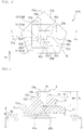
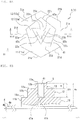
FIG. 2 is a plan view illustrating a shaft of the stud pin according to the first embodiment. -
FIG. 3 is a cross-sectional view ofFIG. 2 taken along a line III-III. -
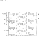
FIG. 4 is a developed view of a tread portion of a pneumatic tire on which the stud pin according to the first embodiment is mounted. -
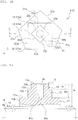
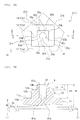
FIG. 5A is a plan view illustrating a shaft of a stud pin according to a second embodiment. -
FIG. 5B is a cross-sectional view ofFIG. 5A taken along a line V-V. -
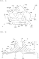
FIG. 6A is a plan view illustrating a shaft of a stud pin according to a third embodiment. -
FIG. 6B is a cross-sectional view ofFIG. 6A taken along a line VI-VI. -
FIG. 7A is a plan view illustrating a shaft of a stud pin according to a fourth embodiment. -
FIG. 7B is a cross-sectional view ofFIG. 7A taken along a line VII-VII. -
FIG. 8A is a plan view illustrating a shaft of a stud pin according to a fifth embodiment. -
FIG. 8B is a cross-sectional view ofFIG. 8A taken along a line VIII-VII. -
FIG. 9A is a plan view illustrating a shaft of a stud pin according to a sixth embodiment. -
FIG. 9B is a cross-sectional view ofFIG. 9A taken along a line IX-IX. -
FIG. 10A is a plan view illustrating a shaft of a stud pin according to a seventh embodiment. -
FIG. 10B is a cross-sectional view ofFIG. 10A taken along a line X-X. -
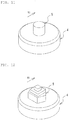
FIG. 11 is a partial perspective view of a stud pin according to Comparative Example 1. -
FIG. 12 is a partial perspective view of a stud pin according to Comparative Example 2. - Embodiments of the present invention will now be described referring to the attached drawings.
- Referring to
FIGs. 1 to 3 , astud pin 1 of this embodiment as a whole has a shape that extends along its axis AX. In the following descriptions, the term "plan view" may be hereinafter used for the shape of thestud pin 1 viewed from its tip side along the axis AX. - The
stud pin 1 comprises: abase 2 on the bottom-most side; ashank 3 protruding from thebase 2; and abody 4 arranged on the tip of theshank 3. Thestud pin 1 further comprises ashaft 5 protruding from thebody 4. - In this embodiment, the
base 2 is substantially disk-shaped, and thebody 4 is substantially cylindrical. Theshank 3 has a substantially short cylindrical shape having a smaller diameter than thebase 2 and thebody 4. Further, thebase 2, theshank 3 and thebody 4 constitute an integrated structure and are made of aluminum or an aluminum alloy. Other structures and other materials can be employed for all of thebase 2, theshank 3 and thebody 4. - The
body 4 comprises anend surface 4a and aside surface 4b. In this embodiment, theend surface 4a is substantially a flat surface that extends perpendicular to the axis AX. Theend surface 4a may be inclined with respect to the axis AX and may be a non-flat surface. Theshaft 5 protrudes from theend surface 4a of thebody 4 in the direction along the axis AX. The outline or outer shape of theshaft 5 in a plan view fits inside a region bounded by the outer shape of theend surface 4a of thebody 4 in the plan view. In other words, the area of the outer shape of theshaft 5 in a plan view is smaller than the area of the outer shape of theend surface 4a of thebody 4 in the plan view. For example, the area of the former can be set at 10 to 45% of the area of the latter. - In this embodiment, the material of the
shaft 5 is tungsten. Theshaft 5 is a separate component from thebase 2, theshank 3 and thebody 4, and is engaged and thereby fixed with thebody 4. As for theshaft 5, other material can be employed. Theshaft 5 and thebody 4 may have an integrated structure as well. - Referring to
FIG. 4 in combination, thestud pin 1 is used by being mounted intopin holes 6b that are formed on atread portion 6a of apneumatic tire 6. Thebase 2 and theshank 3 are entirely housed in eachpin hole 6b. Thebody 4 is housed in eachpin hole 6b with itsend surface 4a and theshaft 5 being exposed on thetread portion 6. - The
shaft 5 has a multi-stepped structure comprising plural steps. In this embodiment, theshaft 5 comprises three steps, namely afirst step 11, asecond step 12 and athird step 13. The first to thethird steps shaft 5 compriseend surfaces side surfaces first step 11, protrudes from theend surface 4a of thebody 4. Further, the intermediate step, namely thesecond step 12, protrudes from theend surface 11a of thefirst step 11. Still further, the endmost step, namely thethird step 13, protrudes from theend surface 12a of thesecond step 12. Theshaft 5 may have four or more steps. Alternatively, theshaft 5 may be constituted by two steps. - The total height of the shaft 5 (in this embodiment, the height from the
end surface 4a of thebody 4 to theend surface 13a of the third step 13) can be set at, for example, 0.5 mm to 3 mm. In addition, the ratio of a sum of the heights of the steps other than the first step 11 (in this embodiment, a sum of the heights of the second and thethird steps 12 and 13) with respect to the total height of the shaft can be set at, for example, 10% to 90%. - In the first to the
third steps shaft 5, the end surfaces 11a, 12a and 13a in a plan view have larger outer shapes toward the side of thebody 4, namely the base-end side. Conversely, in the first to thethird steps shaft 5, the end surfaces 11a, 12a and 13a in a plan view have smaller outer shapes toward the tip side. Accordingly, theshaft 5 as a whole constitutes a pointed protrusion that protrudes in a stepped manner from theend surface 4a of thebody 4. - In this embodiment, the end surfaces 11a, 11b and 11c of the first to the
third steps - As most clearly illustrated in
FIG. 2 , the outer shapes of the end surfaces 11a, 12a and 13a of the first to thethird steps first step 11 whoseend surface 11a is pentagonal, five sides andedge components end surface 11a and theside surface 11b. Further, in thesecond step 12 whoseend surface 12a is quadrangular, four sides andedge components end surface 12a and theside surface 12b. Moreover, in thethird step 13 whoseend surface 13a is quadrangular, four sides andedge components end surface 13a and theside surface 13b. In this embodiment, theedge components 21a to 21e, 22a to 22d and 23a to 23d are linear. However, theseedge components 21a to 21e, 22a to 22d and 23a to 23d are not required to be linear in a geometrically strict sense and may be curved or tortuous to a certain extent as long as a scratching effect on icy and snowy road surfaces is attained. In addition, theseedge components 21a to 21e, 22a to 22d and 23a to 23d may be chamfered as long as a scratching effect on icy and snowy road surfaces is attained. - A
hole 41 having a closed bottom is arranged on theend surface 13a of thethird step 13, which is the endmost step of theshaft 5. In this embodiment, the shape of thehole 41 in a plan view is quadrangular similar to theend surface 13a. Thehole 41 is arranged such that, in a plan view, the position of its centroid is substantially aligned with that of theend surface 13a. In this embodiment, thehole 41 has a uniform cross-sectional shape along the entirety of the depth direction. However, the cross-sectional shape of thehole 41 may vary in the depth direction. - In this embodiment, since the outer shape of the
hole 41 in a plan view is quadrangular, the margin of thehole 41 that is formed by aside wall 41a of thehole 41 and theend surface 13a of thethird step 13 constitutes four sides andedge component edge components 42a to 42d of thehole 41 are linear. However, theseedge components 42a to 42d are not required to be linear in a geometrically strict sense and may be curved or tortuous to a certain extent as long as a scratching effect on icy and snowy road surfaces is attained. In addition, theseedge components 42a to 42d may be chamfered as long as a scratching effect on icy and snowy road surfaces is attained. - Accordingly, by arranging the
hole 41, theshaft 5 is provided with theedge components 42a to 42d of thehole 41 in addition to theedge components 21a to 21e, 22a to 22d and 23a to 23d of the first to thethird steps 11 to 13. In other words, by arranging thehole 41, the total number of the edge components of theshaft 5 and the total length of the edge line segments of the shaft 5 (edge component total length) can be increased. Therefore, by arranging thehole 41, the edge components of theshaft 5 are allowed to function more effectively, whereby the driving performance on icy and snowy road surfaces can be improved. - The total number of the edge components and the edge component total length can also be increased by increasing the total number of the steps of the
shaft 5, instead of arranging the hole. However, in this case, the strength (fracture resistance) of theshaft 5 is reduced due to an increase in total height Ha of theshaft 5. When the total number of the edge components and the edge component total length are increased by arranging thehole 41, a reduction in the strength of the shaft is less likely to occur as compared to a case of increasing the total number of the steps of theshaft 5. - By arranging the
hole 41, thethird step 13, which is the endmost step, is made more likely to pierce icy and snowy road surfaces as compared to a case where thehole 41 is not arranged. In this respect as well, by arranging thehole 41, the driving performance on icy and snowy road surfaces can be improved. - As described above, by arranging the
hole 41 on theend surface 13a of thethird step 13 which is the endmost step, the edge components of theshaft 5 are allowed to function more effectively while securing the strength of theshaft 5, whereby the driving performance on icy and snowy road surfaces can be improved. - The area A1 of a region bounded by the outline of the
end surface 13a of the endmostthird step 13 in a plan view and the area A2 of a region bounded by the margin of thehole 41 in a plan view, namely theedge components 42a to 42d, can be set to be in a range defined by the following inequality.
- By setting the areas A1 and A2 in this range, an increase in the total number of the edge components and the edge component total length, which is attributed to the arrangement of the
hole 42, can be realized while suppressing a reduction in the strength of theshaft 5 caused by the arrangement of thehole 42. - Referring to
FIG. 3 , the depth DEth of thehole 41 is not less than the protruding height Ht of thethird step 13 which is the endmost step (the height from theend surface 12a of thesecond step 12 to theend surface 13a of the third step 13). Specifically, the depth DEth of thehole 41 is set such that abottom wall 41b of thehole 41 is positioned in the vicinity of theend surface 11a of thefirst step 11 which is the bottom-most step. By setting the depth DEth of thehole 41 to be large, thehole 41 remains even when abrasion of theshaft 5, specifically thethird step 13 which is the endmost step, progresses. Moreover, thehole 41 also remains even when abrasion of thesecond step 12 progresses. In other words, even with the progress of abrasion, the advantage of an increase in the total number of the edge components and the edge component total length, which is attained by arranging the hole, is maintained. - As described above, the
end surface 11a of thefirst step 11 has a pentagonal planar shape, and theend surface 12a of thesecond step 12 has a quadrangular planar shape. In other words, thefirst step 11 and thesecond step 12 of theshaft 5 are different in terms of the outer shapes of theirend surfaces edge components 21a to 21e of thefirst step 11 and theedge components 22a to 22d of thesecond step 12 have different orientations in a plan view. More specifically, in a plan view, none of theedge components 22a to 22d of thesecond step 12 is parallel to any of theedge components 21a to 21e of thefirst step 11. In other words, as conceptually illustrated with a symbol E inFIG. 1 , theshaft 5 has edge components oriented in multiple directions, and these edge components act in the multiple directions. As a result, the driving performance on icy and snowy road surfaces is improved. - The
first step 11 has fiveedge components 21a to 21e, and thesecond step 12 has fouredge components 22a to 22d. In addition, theend surface 12a of thesecond step 12 is smaller than theend surface 11a of thefirst step 11. Generally speaking, when the end surfaces of steps have the same size, the larger the number of edge components, the shorter is the length of each edge component. Accordingly, by setting the number of the edge components of thefirst step 11 having the relativelylarge end surface 11a to be relatively large, theedge components 21a to 21e can be ensured in multiple directions while securing the lengths of theindividual edge components 21a to 21e. Moreover, by setting the number of the edge components of thesecond step 12 having the relativelysmall end surface 12a to be relatively small, theedge components 22a to 22d can be ensured in directions different from the directions of theedge components 21a to 21e of thefirst step 11 while securing the lengths of theindividual edge components 22a to 22d. As a result, the driving performance on icy and snowy road surfaces is further improved as compared to a case where the outer shape of theend surface 11a of thefirst step 11 and that of theend surface 12a of thesecond step 12 are simply different. - Other embodiments of the present invention will now be described. With regard to these embodiments, structures and functions that are not particularly mentioned are the same as in the first embodiment. Further, in the drawings relating to these embodiments, the same symbols are assigned to those elements that are identical or similar to the corresponding elements of the first embodiment.
- In the
stud pin 1 according to the second embodiment that is illustrated inFIGs. 5A and 5B , the outer shapes of the end surfaces 11a to 13a of the first to thethird steps 11 to 13 in a plan view are pentagonal, quadrangular and quadrangular, respectively. The outer shape of thehole 41 in a plan view is circular. Thefirst step 11 comprises fiveedge components 21a to 21e, and thesecond step 12 comprises fouredge components 22a to 22d. Further, thethird step 13 comprises fouredge components 23a to 23d. Moreover, the number of the edge components of thehole 41 that is circular can be regarded as infinity. - The
first step 11 and thesecond step 12 have different outer shapes in a plan view, and the number of the edge components of thesecond step 12 is four, which is less than the number of the edge components of thefirst step 11 that is five. - The number of the edge components constituted by the margin of the
hole 41 that is circular in a plan view can be regarded as infinity, and this is larger than the number of theedge components 23a to 23d of thethird step 13 that is quadrangular in a plan view, i.e., four. In this manner, by setting the number of the edge components of thehole 41 to be larger than the number of the edge components of thethird step 13 that is the endmost step, the above-described piercing effect of thethird step 13 on icy and snowy road surfaces, which is attained by arranging thehole 41, is further improved. - In the
stud pin 1 according to the third embodiment that is illustrated inFIGs. 6A and 6B , the outer shapes of the end surfaces 11a to 13a of the first to thethird steps 11 to 13 in a plan view are pentagonal, quadrangular and circular, respectively. The outer shape of thehole 41 in a plan view is quadrangular. Thefirst step 11 comprises fiveedge components 21a to 21e, and thesecond step 12 comprises fouredge components 22a to 22d. Further, the number of the edge components of thethird step 13 that is circular can be regarded as infinity. Moreover, thehole 41 comprises fouredge components 42a to 42d. - The
first step 11 and thesecond step 12 have different outer shapes in a plan view, and the number of the edge components of thesecond step 12 is four, which is less than the number of the edge components of thefirst step 11 that is five. - As described above, the
end surface 13a of thethird step 13 which is the endmost step is circular, and the number of its edge components can be regarded as infinity. Further, theend surface 12a of thesecond step 12, which is the second endmost step, is quadrangular and has fouredge components 22a to 22d. In other words, the number of the edge components of thethird step 13, which is the endmost step, is larger than the number of the edge components of thesecond step 12, which is the second endmost step. - With regard to the first to the
third steps 11 to 13, each step exerts a higher piercing effect on icy and snowy road surfaces as the number of the edge components increases. Moreover, thethird step 13, which is the endmost step, exerts a higher piercing effect on icy and snowy road surfaces as compared to the first and thesecond steps third step 13, which is the endmost step, to be larger than the number of the edge components of thesecond step 12, the piercing effect of theshaft 5 on icy and snowy road surfaces can be effectively improved, and the driving performance on icy and snowy road surfaces can thereby be improved. - In the
stud pin 1 according to the fourth embodiment that is illustrated inFIGs. 7A and 7B , the outer shapes of the end surfaces 11a to 13a of the first to thethird steps 11 to 13 in a plan view are pentagonal, quadrangular and hexagonal, respectively. The outer shape of thehole 41 in a plan view is quadrangular. Thefirst step 11 comprises fiveedge components 21a to 21e, and thesecond step 12 comprises fouredge components 22a to 22d. Further, thethird step 13 comprises sixedge components 13a to 13f. Moreover, thehole 41 comprises fouredge components 42a to 42d. - The
first step 11 and thesecond step 12 have different outer shapes in a plan view, and the number of the edge components of thesecond step 12 is four, which is less than the number of the edge components of thefirst step 11 that is five. In addition, the number of the edge components of thethird step 13, which is the endmost step, is six and thus larger than the number of the edge components of thesecond step 12, which is the second endmost step, of four. - In the
stud pin 1 according to the fifth embodiment that is illustrated inFIGs. 8A and 8B , the outer shapes of the end surfaces 11a to 13a of the first to thethird steps 11 to 13 in a plan view are hexagonal, pentagonal and triangular, respectively. The outer shape of thehole 41 in a plan view is triangular. Thefirst step 11 comprises sixedge components 21a to 21f, and thesecond step 12 comprises fiveedge components 22a to 22e. Further, thethird step 13 comprises threeedge components 13a to 13c. Moreover, thehole 41 comprises threeedge components 42a to 42c. - The
first step 11 and thesecond step 12 have different outer shapes in a plan view, and the number of the edge components of thesecond step 12 is five, which is less than the number of the edge components of thefirst step 11 that is six. - In the
stud pin 1 according to the sixth embodiment that is illustrated inFIGs. 9A and 9B , the outer shapes of the end surfaces 11a to 13a of the first to thethird steps 11 to 13 in a plan view are pentagonal, quadrangular and quadrangular, respectively. The outer shape of thehole 41 in a plan view is pentagonal. Thefirst step 11 comprises fiveedge components 21a to 21e, and thesecond step 12 comprises fouredge components 22a to 22d. Further, thethird step 13 comprises fouredge components 13a to 13d. Moreover, thehole 41 comprises fiveedge components 42a to 42e. - The
first step 11 and thesecond step 12 have different outer shapes in a plan view, and the number of the edge components of thesecond step 12 is four, which is less than the number of the edge components of thefirst step 11 that is five. In addition, the number of the edge components of thehole 41 is six and thus larger than the number of the edge components of thethird step 13, which is the endmost step, of four. - In the
stud pin 1 according to the seventh embodiment that is illustrated inFIGs. 10A and 10B , the outer shapes of the end surfaces 11a to 13a of the first to thethird steps 11 to 13 in a plan view are all circular. Further, the outer shape of thehole 41 in a plan view is also circular. - The
hole 41 is arranged such that the position of its center of gravity in a plan view is different from the position of the center of gravity of theend surface 13a of thethird step 13 in a plan view. For the first to the third embodiments as well, the position of the center of gravity of thehole 41 may be different from the position of the center of gravity of theend surface 13a of thethird step 13. - In all of the first to the seventh embodiments, a
single hole 41 is arranged on theshaft 5. Two or more holes having the same or different shapes in a plan view may be arranged as long as the strength of theshaft 5 can be secured. - As shown in Table 1 below, the stud pins of Comparative Examples 1 and 2 and the first to the fourth embodiments (which were all brand new) were tested to evaluate the drive performance, the braking performance and the turning performance.
- As test tires, tires having a size of 195/65R15 and an air pressure Fr/Re of 220/220 (kPa) were used. In this evaluation test, the test tires were mounted on a test vehicle (1,500 cc, 4WD mid-size sedan), and this test vehicle was driven on an icy road surface. For the evaluation of the edge performance, Comparative Example 2 and the first to the fifth embodiments were each evaluated as an index, taking the edge performance of Comparative Example 1 as 100. The drive performance was evaluated in terms of the time required for the test vehicle to reach 30 m after starting from a stopped state on the icy road surface. The braking performance was evaluated in terms of the braking distance when a braking force was applied by ABS (Antilock Brake System) at a speed of 40 km/h. The turning performance was evaluated in terms of the turning radius when a turn was made at the same speed of 40 km/h.
- As illustrated in
FIG. 11 , thestud pin 1 of Comparative Example 1 has ashaft 5 constituted by a single cylinder, not by a multi-stepped structure. As illustrated inFIG. 12 , thestud pin 1 of the Comparative Example 2 is thestud pin 1 of the first embodiment from which thehole 41 was eliminated. For all of Comparative Examples and the first to the fourth embodiments, the stud pins 1 were mounted on the test tire such that the tire rotational direction was oriented in the direction indicated by the arrow R1 in the drawings.[Table 1] Comparative Example 1 Comparative Example 2 First embodiment ( FIGs. 2 and 3 )Shaft shape Cylindrical First step: pentagonal Second step: quadrangular Third step: quadrangular Hole: none First step: pentagonal Second step: quadrangular Third step: quadrangular Hole: quadrangular Drive performance 100 103 107 Braking performance 100 105 109 Turning performance 100 103 105 Second embodiment ( FIGs. 5A and 5B )Third embodiment ( FIGs. 6A and 6B )Fourth embodiment ( FIGs. 7A and 7B )Shaft shape First step: pentagonal Second step: quadrangular Third step: quadrangular Hole: circular First step: pentagonal Second step: quadrangular Third step: circular Hole: quadrangular First step: pentagonal Second step: quadrangular Third step: hexagonal Hole: quadrangular Drive performance 106 105 107 Braking performance 108 107 109 Turning performance 107 108 109 Fifth embodiment ( FIGs. 8A and 8B )Shaft shape First step: hexagonal Second step: pentagonal Third step: triangular Hole: triangular Drive performance 108 Braking performance 107 Turning performance 110 - The first to the fifth embodiments, in which the
hole 41 was arranged on theshaft 5, exerted superior performance than Comparative Examples 1 and 2 for all of the drive performance, the braking performance and the turning performance. -
- 1:
- stud pin
- 2:
- base
- 3:
- shank
- 4:
- body
- 4a:
- end surface
- 4b:
- side surface
- 5:
- shaft
- 11:
- first step
- 11a:
- end surface
- 11b:
- side surface
- 12:
- second step
- 12a:
- end surface
- 12b:
- side surface
- 13:
- third step
- 13a:
- end surface
- 13b:
- side surface
- 6:
- pneumatic tire
- 6a:
- tread portion
- 6b:
- pin hole
- 21a, 21b, 21c, 21d, 21e, 21f:
- edge component
- 22a, 22b, 22c, 22d, 22e:
- edge component
- 23a, 23b, 23c, 23d, 23e, 23f:
- edge component
- 41:
- hole
- 41a:
- side wall
- 41b:
- bottom wall
- 42a, 42b, 42c, 42d, 42e:
- edge component
Claims (7)
- A stud pin comprising:a body; anda shaft protruding from the body,whereinthe shaft has a multi-stepped structure that comprises plural steps including at least a first step protruding from the body and a second step protruding from the first step, anda hole is arranged on an end surface of an endmost step of the shaft.
- The stud pin according to claim 1, wherein an area A1 bounded by the outline of the end surface of the endmost step in a plan view and an area A2 of the hole satisfy:

- The stud pin according to claim 1 or 2, wherein a depth of the hole is not less than a protruding height of the endmost step.
- The stud pin according to any one of claims 1 to 3, wherein the outer shape of the first step in a plan view and that of the second step in a plan view are different.
- The stud pin according to claim 4, wherein a number of edge components of the second step is less than a number of edge components of the first step.
- The stud pin according to any one of claims 1 to 5, wherein a number of edge components of the endmost step is larger than a number of edge components of a second endmost step.
- The stud pin according to any one of claims 1 to 6, wherein a number of edge components constituted by the margin of the hole is larger than a number of the edge components of the endmost step.
Applications Claiming Priority (2)
| Application Number | Priority Date | Filing Date | Title |
|---|---|---|---|
| JP2016209213A JP6659518B2 (en) | 2016-10-26 | 2016-10-26 | Stud pin |
| PCT/JP2017/021239 WO2018078943A1 (en) | 2016-10-26 | 2017-06-08 | Stud pin and pneumatic tire provided with stud pin |
Publications (2)
| Publication Number | Publication Date |
|---|---|
| EP3533625A1 true EP3533625A1 (en) | 2019-09-04 |
| EP3533625A4 EP3533625A4 (en) | 2020-06-03 |
Family
ID=62024682
Family Applications (1)
| Application Number | Title | Priority Date | Filing Date |
|---|---|---|---|
| EP17863426.7A Withdrawn EP3533625A4 (en) | 2016-10-26 | 2017-06-08 | Stud pin and pneumatic tire provided with stud pin |
Country Status (5)
| Country | Link |
|---|---|
| EP (1) | EP3533625A4 (en) |
| JP (1) | JP6659518B2 (en) |
| CA (1) | CA3040283C (en) |
| RU (1) | RU2711881C1 (en) |
| WO (1) | WO2018078943A1 (en) |
Family Cites Families (8)
| Publication number | Priority date | Publication date | Assignee | Title |
|---|---|---|---|---|
| JPS56134207U (en) * | 1980-03-14 | 1981-10-12 | ||
| JPS5836708A (en) * | 1981-08-26 | 1983-03-03 | Toshio Takayama | Spike pin for car tire |
| JPS5981204A (en) * | 1982-10-30 | 1984-05-10 | Kida Nousan Kk | Nonskid device for automobile tubeless tire |
| JPS59133301U (en) * | 1983-02-28 | 1984-09-06 | 横浜ゴム株式会社 | tire spikes |
| FI119183B (en) * | 2005-12-16 | 2008-08-29 | Scason Oy | Double pin for a stud in a studded deck |
| JP6111010B2 (en) * | 2011-07-22 | 2017-04-05 | 株式会社ブリヂストン | Tire spikes and spike tires |
| JP5997519B2 (en) * | 2012-07-04 | 2016-09-28 | 株式会社ブリヂストン | Pins, tire studs and spike tires |
| JP6087247B2 (en) * | 2013-09-18 | 2017-03-01 | 東洋ゴム工業株式会社 | Tire stud and pneumatic stud tire |
-
2016
- 2016-10-26 JP JP2016209213A patent/JP6659518B2/en not_active Expired - Fee Related
-
2017
- 2017-06-08 WO PCT/JP2017/021239 patent/WO2018078943A1/en not_active Ceased
- 2017-06-08 RU RU2019111643A patent/RU2711881C1/en active
- 2017-06-08 EP EP17863426.7A patent/EP3533625A4/en not_active Withdrawn
- 2017-06-08 CA CA3040283A patent/CA3040283C/en not_active Expired - Fee Related
Also Published As
| Publication number | Publication date |
|---|---|
| WO2018078943A1 (en) | 2018-05-03 |
| RU2711881C1 (en) | 2020-01-23 |
| CA3040283A1 (en) | 2018-05-03 |
| CA3040283C (en) | 2021-05-04 |
| JP2018069827A (en) | 2018-05-10 |
| EP3533625A4 (en) | 2020-06-03 |
| JP6659518B2 (en) | 2020-03-04 |
Similar Documents
| Publication | Publication Date | Title |
|---|---|---|
| JP6149870B2 (en) | Pneumatic tire | |
| EP3098089B1 (en) | Winter tire | |
| EP2977231B1 (en) | Stud pin and tire using same | |
| EP3098090B1 (en) | Winter tire | |
| RU2731835C2 (en) | Stud pin and pneumatic tire | |
| EP3208115B1 (en) | Pneumatic tire | |
| EP2910389A1 (en) | Pneumatic tire | |
| CN110481245B (en) | Motorcycle tire for running on rough terrain | |
| JP2007050718A (en) | Pneumatic stud tire | |
| CA3040283C (en) | Stud pin and pneumatic tire provided with stud pin | |
| WO2016199767A1 (en) | Stud pin and pneumatic tire | |
| CA3040244C (en) | Stud pin and pneumatic tire provided with stud pin | |
| JP4392226B2 (en) | Pneumatic tire | |
| EP3533630A1 (en) | Stud pin and pneumatic tire provided with stud pin | |
| JP6806936B2 (en) | Stud pin | |
| EP3533632A1 (en) | Stud pin, and pneumatic tire provided with stud pin | |
| EP3533627A1 (en) | Stud pin and pneumatic tire provided with stud pin | |
| CA3040256C (en) | Stud pin and pneumatic tire provided with stud pin | |
| WO2020090884A1 (en) | A tire tread for improved snow performance | |
| EP3533628A1 (en) | Stud pin, and pneumatic tire provided with stud pin | |
| CA3040239C (en) | Stud pin and pneumatic tire provided with stud pin | |
| EP3075573A9 (en) | Pneumatic tire | |
| JP2018069825A (en) | Stud pin and pneumatic tire with stud pin | |
| EP3698985B1 (en) | Tire |
Legal Events
| Date | Code | Title | Description |
|---|---|---|---|
| STAA | Information on the status of an ep patent application or granted ep patent |
Free format text: STATUS: THE INTERNATIONAL PUBLICATION HAS BEEN MADE |
|
| PUAI | Public reference made under article 153(3) epc to a published international application that has entered the european phase |
Free format text: ORIGINAL CODE: 0009012 |
|
| STAA | Information on the status of an ep patent application or granted ep patent |
Free format text: STATUS: REQUEST FOR EXAMINATION WAS MADE |
|
| 17P | Request for examination filed |
Effective date: 20190416 |
|
| AK | Designated contracting states |
Kind code of ref document: A1 Designated state(s): AL AT BE BG CH CY CZ DE DK EE ES FI FR GB GR HR HU IE IS IT LI LT LU LV MC MK MT NL NO PL PT RO RS SE SI SK SM TR |
|
| AX | Request for extension of the european patent |
Extension state: BA ME |
|
| DAV | Request for validation of the european patent (deleted) | ||
| DAX | Request for extension of the european patent (deleted) | ||
| A4 | Supplementary search report drawn up and despatched |
Effective date: 20200504 |
|
| RIC1 | Information provided on ipc code assigned before grant |
Ipc: B60C 11/16 20060101AFI20200427BHEP |
|
| GRAP | Despatch of communication of intention to grant a patent |
Free format text: ORIGINAL CODE: EPIDOSNIGR1 |
|
| STAA | Information on the status of an ep patent application or granted ep patent |
Free format text: STATUS: GRANT OF PATENT IS INTENDED |
|
| INTG | Intention to grant announced |
Effective date: 20210303 |
|
| STAA | Information on the status of an ep patent application or granted ep patent |
Free format text: STATUS: THE APPLICATION IS DEEMED TO BE WITHDRAWN |
|
| 18D | Application deemed to be withdrawn |
Effective date: 20210714 |