EP3532327B1 - Hybridantriebsstrang für ein hybridgetriebenes kraftfahrzeug - Google Patents
Hybridantriebsstrang für ein hybridgetriebenes kraftfahrzeug Download PDFInfo
- Publication number
- EP3532327B1 EP3532327B1 EP17791343.1A EP17791343A EP3532327B1 EP 3532327 B1 EP3532327 B1 EP 3532327B1 EP 17791343 A EP17791343 A EP 17791343A EP 3532327 B1 EP3532327 B1 EP 3532327B1
- Authority
- EP
- European Patent Office
- Prior art keywords
- shaft
- electric machine
- hybrid
- combustion engine
- internal combustion
- Prior art date
- Legal status (The legal status is an assumption and is not a legal conclusion. Google has not performed a legal analysis and makes no representation as to the accuracy of the status listed.)
- Active
Links
Images


Classifications
-
- B—PERFORMING OPERATIONS; TRANSPORTING
- B60—VEHICLES IN GENERAL
- B60K—ARRANGEMENT OR MOUNTING OF PROPULSION UNITS OR OF TRANSMISSIONS IN VEHICLES; ARRANGEMENT OR MOUNTING OF PLURAL DIVERSE PRIME-MOVERS IN VEHICLES; AUXILIARY DRIVES FOR VEHICLES; INSTRUMENTATION OR DASHBOARDS FOR VEHICLES; ARRANGEMENTS IN CONNECTION WITH COOLING, AIR INTAKE, GAS EXHAUST OR FUEL SUPPLY OF PROPULSION UNITS IN VEHICLES
- B60K6/00—Arrangement or mounting of plural diverse prime-movers for mutual or common propulsion, e.g. hybrid propulsion systems comprising electric motors and internal combustion engines
- B60K6/20—Arrangement or mounting of plural diverse prime-movers for mutual or common propulsion, e.g. hybrid propulsion systems comprising electric motors and internal combustion engines the prime-movers consisting of electric motors and internal combustion engines, e.g. HEVs
- B60K6/22—Arrangement or mounting of plural diverse prime-movers for mutual or common propulsion, e.g. hybrid propulsion systems comprising electric motors and internal combustion engines the prime-movers consisting of electric motors and internal combustion engines, e.g. HEVs characterised by apparatus, components or means specially adapted for HEVs
- B60K6/36—Arrangement or mounting of plural diverse prime-movers for mutual or common propulsion, e.g. hybrid propulsion systems comprising electric motors and internal combustion engines the prime-movers consisting of electric motors and internal combustion engines, e.g. HEVs characterised by apparatus, components or means specially adapted for HEVs characterised by the transmission gearings
-
- B—PERFORMING OPERATIONS; TRANSPORTING
- B60—VEHICLES IN GENERAL
- B60K—ARRANGEMENT OR MOUNTING OF PROPULSION UNITS OR OF TRANSMISSIONS IN VEHICLES; ARRANGEMENT OR MOUNTING OF PLURAL DIVERSE PRIME-MOVERS IN VEHICLES; AUXILIARY DRIVES FOR VEHICLES; INSTRUMENTATION OR DASHBOARDS FOR VEHICLES; ARRANGEMENTS IN CONNECTION WITH COOLING, AIR INTAKE, GAS EXHAUST OR FUEL SUPPLY OF PROPULSION UNITS IN VEHICLES
- B60K6/00—Arrangement or mounting of plural diverse prime-movers for mutual or common propulsion, e.g. hybrid propulsion systems comprising electric motors and internal combustion engines
- B60K6/20—Arrangement or mounting of plural diverse prime-movers for mutual or common propulsion, e.g. hybrid propulsion systems comprising electric motors and internal combustion engines the prime-movers consisting of electric motors and internal combustion engines, e.g. HEVs
- B60K6/42—Arrangement or mounting of plural diverse prime-movers for mutual or common propulsion, e.g. hybrid propulsion systems comprising electric motors and internal combustion engines the prime-movers consisting of electric motors and internal combustion engines, e.g. HEVs characterised by the architecture of the hybrid electric vehicle
- B60K6/48—Parallel type
-
- B—PERFORMING OPERATIONS; TRANSPORTING
- B60—VEHICLES IN GENERAL
- B60K—ARRANGEMENT OR MOUNTING OF PROPULSION UNITS OR OF TRANSMISSIONS IN VEHICLES; ARRANGEMENT OR MOUNTING OF PLURAL DIVERSE PRIME-MOVERS IN VEHICLES; AUXILIARY DRIVES FOR VEHICLES; INSTRUMENTATION OR DASHBOARDS FOR VEHICLES; ARRANGEMENTS IN CONNECTION WITH COOLING, AIR INTAKE, GAS EXHAUST OR FUEL SUPPLY OF PROPULSION UNITS IN VEHICLES
- B60K6/00—Arrangement or mounting of plural diverse prime-movers for mutual or common propulsion, e.g. hybrid propulsion systems comprising electric motors and internal combustion engines
- B60K6/20—Arrangement or mounting of plural diverse prime-movers for mutual or common propulsion, e.g. hybrid propulsion systems comprising electric motors and internal combustion engines the prime-movers consisting of electric motors and internal combustion engines, e.g. HEVs
- B60K6/50—Architecture of the driveline characterised by arrangement or kind of transmission units
- B60K6/54—Transmission for changing ratio
- B60K6/547—Transmission for changing ratio the transmission being a stepped gearing
-
- F—MECHANICAL ENGINEERING; LIGHTING; HEATING; WEAPONS; BLASTING
- F16—ENGINEERING ELEMENTS AND UNITS; GENERAL MEASURES FOR PRODUCING AND MAINTAINING EFFECTIVE FUNCTIONING OF MACHINES OR INSTALLATIONS; THERMAL INSULATION IN GENERAL
- F16H—GEARING
- F16H3/00—Toothed gearings for conveying rotary motion with variable gear ratio or for reversing rotary motion
- F16H3/02—Toothed gearings for conveying rotary motion with variable gear ratio or for reversing rotary motion without gears having orbital motion
- F16H3/08—Toothed gearings for conveying rotary motion with variable gear ratio or for reversing rotary motion without gears having orbital motion exclusively or essentially with continuously meshing gears, that can be disengaged from their shafts
- F16H3/087—Toothed gearings for conveying rotary motion with variable gear ratio or for reversing rotary motion without gears having orbital motion exclusively or essentially with continuously meshing gears, that can be disengaged from their shafts characterised by the disposition of the gears
- F16H3/093—Toothed gearings for conveying rotary motion with variable gear ratio or for reversing rotary motion without gears having orbital motion exclusively or essentially with continuously meshing gears, that can be disengaged from their shafts characterised by the disposition of the gears with two or more countershafts
-
- B—PERFORMING OPERATIONS; TRANSPORTING
- B60—VEHICLES IN GENERAL
- B60K—ARRANGEMENT OR MOUNTING OF PROPULSION UNITS OR OF TRANSMISSIONS IN VEHICLES; ARRANGEMENT OR MOUNTING OF PLURAL DIVERSE PRIME-MOVERS IN VEHICLES; AUXILIARY DRIVES FOR VEHICLES; INSTRUMENTATION OR DASHBOARDS FOR VEHICLES; ARRANGEMENTS IN CONNECTION WITH COOLING, AIR INTAKE, GAS EXHAUST OR FUEL SUPPLY OF PROPULSION UNITS IN VEHICLES
- B60K6/00—Arrangement or mounting of plural diverse prime-movers for mutual or common propulsion, e.g. hybrid propulsion systems comprising electric motors and internal combustion engines
- B60K6/20—Arrangement or mounting of plural diverse prime-movers for mutual or common propulsion, e.g. hybrid propulsion systems comprising electric motors and internal combustion engines the prime-movers consisting of electric motors and internal combustion engines, e.g. HEVs
- B60K6/42—Arrangement or mounting of plural diverse prime-movers for mutual or common propulsion, e.g. hybrid propulsion systems comprising electric motors and internal combustion engines the prime-movers consisting of electric motors and internal combustion engines, e.g. HEVs characterised by the architecture of the hybrid electric vehicle
- B60K6/48—Parallel type
- B60K2006/4833—Step up or reduction gearing driving generator, e.g. to operate generator in most efficient speed range
- B60K2006/4841—Step up or reduction gearing driving generator, e.g. to operate generator in most efficient speed range the gear provides shifting between multiple ratios
-
- F—MECHANICAL ENGINEERING; LIGHTING; HEATING; WEAPONS; BLASTING
- F16—ENGINEERING ELEMENTS AND UNITS; GENERAL MEASURES FOR PRODUCING AND MAINTAINING EFFECTIVE FUNCTIONING OF MACHINES OR INSTALLATIONS; THERMAL INSULATION IN GENERAL
- F16H—GEARING
- F16H3/00—Toothed gearings for conveying rotary motion with variable gear ratio or for reversing rotary motion
- F16H3/02—Toothed gearings for conveying rotary motion with variable gear ratio or for reversing rotary motion without gears having orbital motion
- F16H3/08—Toothed gearings for conveying rotary motion with variable gear ratio or for reversing rotary motion without gears having orbital motion exclusively or essentially with continuously meshing gears, that can be disengaged from their shafts
- F16H2003/0826—Toothed gearings for conveying rotary motion with variable gear ratio or for reversing rotary motion without gears having orbital motion exclusively or essentially with continuously meshing gears, that can be disengaged from their shafts wherein at least one gear on the input shaft, or on a countershaft is used for two different forward gear ratios
-
- F—MECHANICAL ENGINEERING; LIGHTING; HEATING; WEAPONS; BLASTING
- F16—ENGINEERING ELEMENTS AND UNITS; GENERAL MEASURES FOR PRODUCING AND MAINTAINING EFFECTIVE FUNCTIONING OF MACHINES OR INSTALLATIONS; THERMAL INSULATION IN GENERAL
- F16H—GEARING
- F16H3/00—Toothed gearings for conveying rotary motion with variable gear ratio or for reversing rotary motion
- F16H3/02—Toothed gearings for conveying rotary motion with variable gear ratio or for reversing rotary motion without gears having orbital motion
- F16H3/08—Toothed gearings for conveying rotary motion with variable gear ratio or for reversing rotary motion without gears having orbital motion exclusively or essentially with continuously meshing gears, that can be disengaged from their shafts
- F16H3/087—Toothed gearings for conveying rotary motion with variable gear ratio or for reversing rotary motion without gears having orbital motion exclusively or essentially with continuously meshing gears, that can be disengaged from their shafts characterised by the disposition of the gears
- F16H3/093—Toothed gearings for conveying rotary motion with variable gear ratio or for reversing rotary motion without gears having orbital motion exclusively or essentially with continuously meshing gears, that can be disengaged from their shafts characterised by the disposition of the gears with two or more countershafts
- F16H2003/0933—Toothed gearings for conveying rotary motion with variable gear ratio or for reversing rotary motion without gears having orbital motion exclusively or essentially with continuously meshing gears, that can be disengaged from their shafts characterised by the disposition of the gears with two or more countershafts with coaxial countershafts
-
- F—MECHANICAL ENGINEERING; LIGHTING; HEATING; WEAPONS; BLASTING
- F16—ENGINEERING ELEMENTS AND UNITS; GENERAL MEASURES FOR PRODUCING AND MAINTAINING EFFECTIVE FUNCTIONING OF MACHINES OR INSTALLATIONS; THERMAL INSULATION IN GENERAL
- F16H—GEARING
- F16H2200/00—Transmissions for multiple ratios
- F16H2200/003—Transmissions for multiple ratios characterised by the number of forward speeds
- F16H2200/0069—Transmissions for multiple ratios characterised by the number of forward speeds the gear ratios comprising ten forward speeds
-
- Y—GENERAL TAGGING OF NEW TECHNOLOGICAL DEVELOPMENTS; GENERAL TAGGING OF CROSS-SECTIONAL TECHNOLOGIES SPANNING OVER SEVERAL SECTIONS OF THE IPC; TECHNICAL SUBJECTS COVERED BY FORMER USPC CROSS-REFERENCE ART COLLECTIONS [XRACs] AND DIGESTS
- Y02—TECHNOLOGIES OR APPLICATIONS FOR MITIGATION OR ADAPTATION AGAINST CLIMATE CHANGE
- Y02T—CLIMATE CHANGE MITIGATION TECHNOLOGIES RELATED TO TRANSPORTATION
- Y02T10/00—Road transport of goods or passengers
- Y02T10/60—Other road transportation technologies with climate change mitigation effect
- Y02T10/62—Hybrid vehicles
Definitions
- the invention relates to a hybrid drive train for a hybrid-drive motor vehicle according to the preamble of patent claim 1 or patent claim 6.
- a hybrid powertrain for a hybrid-powered vehicle is known.
- This has a gear that can be switched to different gear ratios by means of shifting elements and that can be drivingly connected via an internal combustion engine shaft to an internal combustion engine, via an electric machine shaft to an electric machine and via an output shaft to at least one vehicle axle.
- the internal combustion engine shaft can be connected to an output shaft via spur gear sets forming wheel planes. This in turn drives the output shaft via a spur gear stage.
- the wheel planes of the hybrid transmission have a hybrid wheel plane that is drivingly connected to the electric motor shaft.
- a generic drive train for a vehicle and a method for shifting such a drive train is known.
- a transmission-integrated electric machine for a motor vehicle internal combustion engine is known.
- a method for operating a hybrid drive system is known.
- a device for transmitting drive power for a vehicle is known.
- a motion transmission device for hybrid vehicles is known.
- the object of the invention is to provide a hybrid drive train which, in comparison to the prior art, has greater degrees of freedom in terms of functionality in a structurally simple, space-saving design.
- the wheel planes V1 to V4, E1, E2 have a first and a second hybrid wheel plane E1, E2. These can also be drivingly connected to the electric machine shaft and are designed in such a way that the electric machine can be connected to the internal combustion engine via the first hybrid wheel plane E1, forming a first load path L1. As an alternative to this, the electric machine can be connected to the internal combustion engine, forming a second load path L2. When the first or second load path L1, L2 is switched on, the output shaft connected to the output shaft is decoupled from the respective load path L1, L2.
- the first load path L1 can be designed for stationary charging operation, in which the internal combustion engine is connected to the electric machine in a torque flow direction via the first hybrid wheel plane E1.
- the first hybrid wheel plane E1 is designed in such a way that there is a high transmission ratio from the internal combustion engine to the electric machine.
- the second load path L2 can be designed for an internal combustion engine start, in which the electric machine in a torque flow direction via the second hybrid wheel plane E2 with the Internal combustion engine is connected.
- the second hybrid wheel plane E2 is designed in such a way that there is a high transmission ratio from the electric machine to the internal combustion engine.
- first and second hybrid wheel planes E1, E2 can be used to provide electric motor transmission gears with a high torque for starting and with long transmission ratios for high speeds.
- first and second hybrid wheel planes E1, E2 can be used to provide electromotive transmission gears for boost operation from the electric machine to the vehicle wheel and for recuperation operation from the vehicle wheel to the electric machine.
- the respective hybrid gear plane E1, E2 is made up of an output-side gear wheel arranged on the output shaft, a drive-side gear wheel arranged on the internal combustion engine shaft and a gear wheel arranged on the electric machine shaft.
- the gear wheel arranged on the electric machine shaft is rotatably mounted as a loose gear wheel on the electric machine shaft and can be decoupled from or coupled to the electric machine shaft by means of the switching element SE-A.
- the shifting element SE-A arranged on the electric machine shaft can be shiftable on both sides and can be arranged in the axial direction between the idler gears of the two hybrid gear planes E1, E2.
- the switching element SE-A can either couple the idler gear of the first hybrid gear plane E1 to the electric machine shaft in a first shift position or couple the idler gear of the second hybrid gear plane E2 to the electric machine shaft in a second shift position.
- the electric machine shaft is completely free of fixed gears of the spur gear sets which are arranged thereon in a torque-proof manner and which form the gear planes of the transmission.
- the transmission is designed as a pure spur gear transmission, in which the internal combustion engine shaft, the electric machine shaft and the output shaft can be drivingly connected to one another exclusively via spur gear sets. In this way, a simply designed transmission structure is achieved, which can be operated much more efficiently compared to a planetary gear.
- each of the hybrid gear planes E1, E2 has an output-side gear wheel arranged on the output shaft, which is designed as an idler gear wheel and can be coupled to the output shaft by means of a shifting element SE-B.
- the gears on the drive side of the two hybrid gear planes E1, E2, which are arranged on the internal combustion engine shaft, are designed as loose gears.
- the above-mentioned shifting element SE-B which is arranged on the output shaft, can be designed to be shiftable on both sides and can be arranged in the axial direction between the idler gear wheels on the output side of the two hybrid gear planes E1, E2.
- the respective hybrid gear plane E1, E2 is combined with another gear plane V3, V4 to form a first and a second partial transmission T1, T2.
- the first and second sub-transmissions T1, T2 can be deactivated during transmission operation, that is to say can be decoupled or shut down from the drive train.
- the additional gear plane mentioned above is not connected to the electric motor shaft and has an idler gear wheel on the output shaft that is rotatably mounted on the output shaft and can be coupled to the output shaft by means of a shifting element SE-D, SE-E.
- the shifting element SE-D, SEE arranged on the output shaft can be shifted on both sides and is arranged in the axial direction between the idle gear wheels on the output side of the hybrid gear plane E1, E2 and the further gear plane V3, V4, which are rotatably mounted on the output shaft.
- the further wheel planes V3, V4 mentioned above also have a drive-side idler gear rotatably mounted on the internal combustion engine shaft. This can be coupled to the internal combustion engine shaft by means of a switching element SE-F.
- the drive-side idler gears of the respective hybrid gear planes E1, E2 and the other gear planes V3, V4, which are rotatably mounted on the internal combustion engine shaft, are arranged in a rotationally fixed manner on a common drive-side hollow shaft, which are coaxially rotatably mounted on the internal combustion engine shaft and have exactly one shifting element SE-F can be coupled with the internal combustion engine shaft.
- the shifting element SE-F arranged on the internal combustion engine shaft can preferably be shiftable on both sides and can be arranged in the axial direction between the drive-side hollow shafts of the two sub-transmissions T1, T2.
- the switching element arranged on the electric machine shaft can be implemented in any way, for example as a power-shiftable free clutch in combination with a clutch, as a power-shiftable dual clutch or as a non-power-shiftable dual synchronization.
- the electric machine can be connected to the drive side or the output side in the transmission.
- the gear wheel of the hybrid gear plane E1, E2 arranged on the electric machine shaft can mesh with a drive-side idler gear wheel which is rotatably mounted on the internal combustion engine shaft.
- the gearwheel of the hybrid gear plane E1, E2 arranged on the electric machine shaft can mesh with an idler gearwheel on the output side that is rotatably mounted on the output shaft.
- the above hybrid concept can be implemented in a simple manner based on a conventional manual transmission and can be used specifically for the front-wheel drive.
- the rear axle can optionally be mechanically decoupled from the front axle, but can be driven via separate electric machines in order to implement four-wheel drive.
- the electric machine can preferably be positioned at the transmission end.
- a manual transmission 1 is shown, which is part of a hybrid drive train of a hybrid motor vehicle, not shown.
- the transmission 1 which can be switched to different gear ratios by means of shifting elements, is connected to an internal combustion engine 7 via an internal combustion engine shaft 3 with an interposed separating clutch 4 and torsional damper 5 , and is connected to an electric machine 11 via an electric machine shaft 9 .
- the electric machine 11 can be used for torque conversion in the figure 1 shown planetary reduction gear 12 have.
- the transmission 1 is drivingly connected on the output side via an output shaft 13 to a front axle VA of the motor vehicle.
- the output shaft 13 is operatively connected as a pinion shaft to the bevel gear of a front axle differential 15 .
- the internal combustion engine shaft 3, the electric machine shaft 9 and an intermediate output shaft 17 are arranged axially parallel to one another.
- the output shaft 17, the electric machine shaft 9 and the output shaft 13 can be drivenly connected to one another via spur gear sets, which can be switched via the switching elements.
- the spur gear sets form mutually parallel gear planes V1 to V4 and E1 and E2, which according to the figure 1 are all located between the internal combustion engine 7 and the electric machine 11 in the axial direction.
- each hybrid gear plane E1, E2 has an output-side gear wheel 19, 21 arranged on the output shaft 17, which is in each case connected to a drive-side gear wheel 23, 25 arranged on the internal combustion engine shaft 3 and to a respective one arranged coaxially to the electric machine shaft 9 (on the electric machine side ) Loose gear 27, 29 meshes.
- the drive-side gears 23, 25 of the hybrid gear planes E1, E2 are rotatably mounted on the internal combustion engine shaft 3 as loose gears.
- the output shaft 17 drives the output shaft 13 via a spur gear St.
- the electric machine shaft 9 is decoupled from the drive train. In this way, the electric machine shaft 9 is shut down in transmission mode, ie deactivated. This advantageously reduces the moment of inertia of the remaining activated gear.
- the gears of the hybrid gear planes E1, E2 remain activated, ie they are also rotated in the transmission mode despite the electric machine 11 being shut down.
- the two hybrid wheel planes E1, E2 are combined into a common sub-transmission T, which can be switched completely torque-free in transmission mode, i.e. can be completely decoupled from the drive train, so that the sub-transmission T is completely shut down.
- the two output-side gears 19, 21 of the hybrid gear planes E1, E2 are rotatably mounted on the output shaft 17 as idler gears.
- a shifting element SE-B is arranged between the two output-side gears 19, 21 of the hybrid gear planes E1 and E2, which can be shifted on both sides and can couple either the first or the second hybrid gear plane E1, E2 to the output shaft.
- the two drive-side idler gears 23, 25 of the hybrid gear planes E1, E2 are arranged together in a rotationally fixed manner on a drive-side hollow shaft 31, which is rotatably mounted coaxially on the internal combustion engine shaft 3.
- the drive-side hollow shaft 31 can be coupled to the internal combustion engine shaft 3 in a manner with fewer components via exactly one shifting element SE-C.
- a total of two sub-transmissions T1, T2 are provided, which can each be switched completely torque-free in transmission mode, i.e. can be completely decoupled from the drive train, so that the first sub-transmission T1 and/or the second sub-transmission T2 is completely shut down.
- the first hybrid gear plane E1 and another gear plane V4 that is directly axially adjacent are combined.
- the second hybrid gear plane E2 and an immediately adjacent further gear plane V3 are combined with one another.
- the gear plane V4 has a loose gear wheel 33 on the output side that is rotatably mounted on the output shaft 17 .
- the output side Loose gear 33 of gear plane V4 and output-side loose gear 19 of first hybrid gear plane E1 can be alternately coupled to output shaft 17 via a switching element SE-D that is arranged in between and can be shifted on both sides.
- Both the first hybrid gear plane E1 and the gear plane V4 have drive-side idler gears 23, 35 that are rotatably mounted on the internal combustion engine shaft 3 and that are jointly arranged in a rotationally fixed manner on a first hollow shaft 37 on the drive side. This is rotatably mounted coaxially on the internal combustion engine shaft 3 and can be coupled to the internal combustion engine shaft 3 via a switching element SE-F.
- the second sub-transmission T2 has the same construction as the first sub-transmission T1.
- the gear plane V3 has a loose gear wheel 39 on the output side that is rotatably mounted on the output shaft 17 .
- the output-side idler gear 39 of the gear plane V3 and the output-side idler gear 21 of the second hybrid gear plane E2 can be alternately coupled to the output shaft 17 via a shifting element SE-E arranged in between that can be shifted on both sides.
- Both the second hybrid gear plane E2 and the gear plane V3 have drive-side idler gears 25, 41 rotatably mounted on the internal combustion engine shaft 3, which are jointly arranged in a rotationally fixed manner on a drive-side second hollow shaft 43, which is coaxially rotatably mounted on the internal combustion engine shaft 3 and can be coupled to the internal combustion engine shaft 3 via the switching element SE-F.
- the switching element SE-F common to the two hollow shafts 37, 43 can be switched on both sides and is arranged between the two hollow shafts 37, 43 on the drive side.
- the dual clutch has a Outer disk carrier 45, which is connected to the electric motor shaft 9 in a torque-proof manner.
- the outer disk carrier 45 interacts with two inner disk carriers 47, 49 arranged next to one another in the axial direction.
- the inner disk carrier 49 is arranged on a hollow shaft 51 in a torque-proof manner together with the gear wheel 27 on the electric machine side of the first hybrid gear plane E1.
- the inner disk carrier 47 is arranged together with the gear 29 of the second hybrid gear plane E2 in a torque-proof manner on a solid shaft 53 which extends coaxially through the hollow shaft 51 .
- Transmission 1 shown has a total of 16 gears, four synchronizations and two clutches K1, K2.
- Up to ten internal combustion engine gears can be shifted in the transmission 1, i.e. the six internal combustion engine direct gears VM1 to VM6 explained below, which only use one wheel plane, and the four twisting gears VM7 to VM10, which use at least two wheel planes:
- the shifting element SE-H is shifted to the left or to the right, while the two partial transmissions T1, T2 are shut down.
- direct gear VM3 SE-F is shifted to the right and SE-D to the left. This means that the partial transmission T1 is activated and the partial transmission T2 is deactivated.
- direct gear VM4 in which SE-F is shifted to the right and SE-D is also shifted to the right.
- direct gears VM5 and VM6 the partial transmission T2 is activated and the partial transmission T1 is deactivated.
- SE-F is shifted to the left and SE-E to the left.
- SE-F is shifted to the left and SE-E to the right.
- Transmission 1 shown can be switched up to 8 electric motor gears, i.e. the following two direct gears EM1, EM2 and the six twisting gears EM3 to EM8:
- direct gear EM1 clutch K1 is actuated and shifting element SE-D is shifted to the left.
- direct gear EM2 clutch K2 is actuated and shifting element SE-E is shifted to the left.
- electric motor torsion gear EM3 clutch K1 is actuated and SE-D is shifted to the right.
- twisting gear EM4 clutch K1 is actuated and SE-F is shifted to the right and SE-H is shifted to the left.
- twisting gear E5 In twisting gear E5, clutch K1 is actuated, SE-F is shifted to the right and SE-H is shifted to the right. In twisting gear EM6, clutch K2 is actuated and SE-E is shifted to the right. In twisting gear EM7, the second clutch K2 is actuated, SE-F is shifted to the left and SE-H is shifted to the left. In twisting gear EM8, clutch K2 is actuated, SE-F is shifted to the left and SE-H is shifted to the right.
- an internal combustion engine can be started with the aid of the electric machine 11 .
- the electric machine 11 can start the internal combustion engine 7 via a load path L2, in which, for example, the second clutch K2 (consisting of the outer disk carrier 45 and the inner disk carrier 47) is closed and the switching element SE-F is actuated to the left.
- a shifting process between the internal combustion engine gears 1 to 6 with the aid of the electric machine 11 without traction interruption for example with the aid of the electric motor gears EM1, EM2, which act as supporting gears when shifting with the internal combustion engine.
- Such a switching process is with a Opening of the separating clutch 4 started in order to decouple the internal combustion engine 7 from the transmission 1 .
- An engaged electromotive support gear provides a support load path, which runs from the electric machine 11 to the drive side, during the shifting process taking place between the internal combustion engine gears.
- the electric machine 11 can thus generate a drive torque that is transmitted to the output side via the supporting load path.
- the electric motor gear EM2 which acts as a support gear, is engaged, that is to say the multi-plate clutch K2 is closed and the shifting element SE-E is shifted to the left, and the electric machine 11 is run up. This results in a load transfer from the electric machine 11 to the output side, in which the electric machine 11 generates an arbitrarily adjustable torque.
- the shifting process into the target gear VM4 is continued by shifting the shifting element SE-D from its neutral position to the right. This means that there is a load path from internal combustion engine 7 via shifting element SE-F, gear plane V4, shifting element SE-D and output shaft 17 prepared up to the spur gear St on the output side.
- the separating clutch 4 is closed again, i.e. the internal combustion engine 7 is switched on and the electric machine 11 is shut down again, so that the target gear VM4 is engaged and a load is again transferred from the internal combustion engine 7 to the output side.
- each circuit can be supported by means of an electromotive support gear, in contrast to the figure 1 , in which specifically a shifting process between the internal combustion engine third gear VM3 and the internal combustion engine fourth gear VM4, i.e. between the hybrid wheel planes E1 and E2, cannot be supported by means of an electric motor gear.
- Transmission 1 shown cannot be provided by electric machine 11 during the above shifting process, since both internal combustion engine 7 and electric machine 11 drive output shaft 17 via a common shifting element SE-B.
- shifting between the third and fourth internal combustion engine gear without an interruption in traction is not possible.
- Transmission 1 shown enables an electric motor starting from the vehicle standstill or a boost mode, in which several electric motor gears are available for boosting individual internal combustion engine gears.
- Gear 27 on the electric machine side of first hybrid gear level E1 can be connected to hollow shaft 51 via overrunning clutch F.
- the one-way clutch F is assigned a shifting element SE-I, which can be shifted into two operating positions: In the operating position shown, torque is transmitted from the electric machine shaft 9 via the outer disk carrier 45 and via the hollow shaft 51 in the direction of the gear wheel 27 on the electric machine side of the first hybrid -Enables wheel level E1 and activates the freewheel function in the opposite direction, i.e. torque transmission is prevented. So if the overrunning clutch inner side 58 connected to the hollow shaft 51 rotates faster than the gear wheel 27 on the electric machine side, the hollow shaft 51 drives the gear wheel 27 .
- the switching element SE-I In a second operating position, the switching element SE-I is in the figure 3 switched to the left. In this case, torque can be transmitted in both directions. Both in the figure 3 as well as in the figure 2 the electric motor gears are power-shiftable, while in the figure 1 the electric motor gears cannot be shifted under load.
- the electric machine 11 is no longer connected to the transmission 1 on the output side (as in Figs Figures 1 to 3 ), but connected to the transmission 1 on the drive side.
- the electric machine-side gears 27, 29 of the hybrid gear planes E1 and E2 no longer mesh with the output-side Gears 19, 21 of the hybrid gear planes E1 and E2, but with the drive-side gears 23, 25 of the hybrid gear planes E1 and E2.
Landscapes
- Engineering & Computer Science (AREA)
- Mechanical Engineering (AREA)
- Chemical & Material Sciences (AREA)
- Combustion & Propulsion (AREA)
- Transportation (AREA)
- General Engineering & Computer Science (AREA)
- Hybrid Electric Vehicles (AREA)
- Arrangement Of Transmissions (AREA)
- Electric Propulsion And Braking For Vehicles (AREA)
- Structure Of Transmissions (AREA)
Description
- Die Erfindung betrifft einen Hybridantriebsstrang für ein hybridgetriebenes Kraftfahrzeug nach dem Oberbegriff des Patentanspruches 1 oder des Patentanspruches 6.
- Aus der
EP 2 792 523 A2 ist ein Hybridantriebsstrang für ein hybridgetriebenes Fahrzeug bekannt. Dieser weist ein mittels Schaltelemente in unterschiedliche Übersetzungsstufen umschaltbares Getriebe auf, das über eine Brennkraftmaschinen-Welle mit einer Brennkraftmaschine, über eine Elektromaschinen-Welle mit einer Elektromaschine sowie über eine Ausgangswelle mit zumindest einer Fahrzeugachse trieblich verbindbar ist. Die Brennkraftmaschinen-Welle ist über, Radebenen bildende Stirnzahnradsätze mit einer Abtriebswelle verbindbar. Diese treibt wiederum über eine Stirnradstufe auf die Ausgangswelle ab. Die Radebenen des Hybridgetriebes weisen eine Hybrid-Radebene auf, die trieblich mit der Elektromaschinen-Welle verbunden ist. - Aus der
DE 10 2013 210 013 A1 ist ein gattungsgemäßer Antriebsstrang für ein Fahrzeug sowie ein Verfahren zum Schalten eines solchen Antriebsstranges bekannt. Aus derDE 197 45 995 A1 ist eine getriebeintegrierte Elektromaschine für eine Kraftfahrzeug-Brennkraftmaschine bekannt. Aus derWO 2008/138387 A1 ist ein Verfahren zum Betrieb eines Hybridantriebssystems bekannt. Aus derDE 103 29 109 A1 ist eine Vorrichtung zur Übertragung von Antriebsleistung für ein Fahrzeug bekannt. Aus derDE 602 12 220 T2 ist eine Bewegungsübertragungsvorrichtung für Hybridfahrzeuge bekannt. - Die Aufgabe der Erfindung besteht darin, einen Hybridantriebsstrang bereitzustellen, der in einer im Vergleich zum Stand der Technik baulich einfachen, bauraumgünstigen Konstruktion größere Freiheitsgrade in der Funktionalität aufweist.
- Die Aufgabe ist durch die Merkmale des Patentanspruches 1 oder 6 gelöst. Bevorzugte Weiterbildungen der Erfindung sind in den abhängigen Ansprüchen offenbart.
- Erfindungsgemäß weisen die Radebenen V1 bis V4, E1, E2 eine erste und eine zweite Hybrid-Radebene E1, E2 auf. Diese sind zusätzlich mit der Elektromaschinen-Welle trieblich verbindbar und so ausgelegt, dass die Elektromaschine unter Bildung eines ersten Lastpfads L1 über die erste Hybrid-Radebene E1 mit der Brennkraftmaschine verbindbar ist. Alternativ dazu kann die Elektromaschine unter Bildung eines zweiten Lastpfads L2 mit der Brennkraftmaschine verbunden werden. Bei geschaltetem ersten oder zweiten Lastpfad L1, L2 ist die mit der Ausgangswelle verbundene Abtriebswelle vom jeweiligen Lastpfad L1, L2 entkoppelt.
- Beispielhaft kann der erste Lastpfad L1 für einen Standlade-Betrieb ausgelegt sein, bei dem die Brennkraftmaschine in einer Momentenflußrichtung über die erste Hybrid-Radebene E1 mit der Elektromaschine verbunden ist. Die erste Hybrid-Radebene E1 ist dabei so ausgelegt, dass sich eine große Übersetzung von der Brennkraftmaschine zur Elektromaschine ergibt.
- Demgegenüber kann der zweite Lastpfad L2 für einen Brennkraftmaschinen-Start ausgelegt sein, bei dem die Elektromaschine in einer Momentenflußrichtung über die zweite Hybrid-Radebene E2 mit der Brennkraftmaschine verbunden ist. Die zweite Hybrid-Radebene E2 ist dabei so ausgelegt, dass sich eine große Übersetzung von der Elektromaschine zur Brennkraftmaschine ergibt.
- Zudem sind mittels der ersten und zweiten Hybrid-Radebenene E1, E2 elektromotorische Übersetzungsgänge mit einem hohen Drehmoment zum Anfahren sowie mit langen Übersetzungen für hohe Geschwindigkeiten bereitstellbar. Außerdem sind mittels der ersten und zweiten Hybrid-Radebenene E1, E2 elektromotorische Übersetzungsgänge für einen Boost-Betrieb von der Elektromaschine zum Fahrzeugrad sowie für einen Rekuperations-Betrieb vom Fahrzeugrad zur Elektromaschine bereitstellbar.
- Erfindungsgemäß ist die jeweilige Hybrid-Radebene E1, E2 aus einem auf der Abtriebswelle angeordneten abtriebsseitigen Zahnrad, einem auf der Brennkraftmaschinen-Welle angeordneten antriebsseitigen Zahnrad und einem auf der Elektromaschinen-Welle angeordneten Zahnrad aufgebaut. Das auf der Elektromaschinen-Welle angeordnete Zahnrad ist als ein Loszahnrad auf der Elektromaschinen-Welle drehgelagert und mittels des Schaltelements SE-A von der Elektromaschinen-Welle abkoppelbar oder damit koppelbar.
- Das auf der Elektromaschinen-Welle angeordnete Schaltelement SE-A kann beidseitig schaltbar sein und in Axialrichtung zwischen den Loszahnrädern der beiden Hybrid-Radebenen E1, E2 angeordnet sein. Das Schaltelement SE-A kann entweder in einer ersten Schaltstellung das Loszahnrad der ersten Hybrid-Radebene E1 mit der Elektromaschinen-Welle koppeln oder in einer zweiten Schaltstellung das Loszahnrad der zweiten Hybrid-Radebene E2 mit der Elektromaschinen-Welle koppeln.
- Bevorzugt ist es, wenn die Elektromaschinen-Welle gänzlich frei von darauf drehfest angeordneten Festzahnrädern der Stirnzahnradsätze ist, die die Radebenen des Getriebes bilden.
- Zudem ist es bevorzugt, wenn das Getriebe als ein reines Stirnradgetriebe, ausgelegt ist, bei dem die Brennkraftmaschinen-Welle, die Elektromaschinen-Welle und die Ausgangswelle ausschließlich über Stirnzahnradsätze miteinander trieblich verbindbar sind. Auf diese Weise wird eine einfach aufgebaute Getriebestruktur erzielt, die im Vergleich zu einem Planetengetriebe wesentlich effizienter betreibbar ist.
- Erfindungsgemäß sind die beiden Hybrid-Radebenen in der Axialrichtung unmittelbar benachbart und zusammen zu einem gemeinsamen Teilgetriebe T zusammengefasst, das im Getriebe-Betrieb stillgelegt ist, das heißt vom Antriebsstrang abgekoppelt ist. Zur Realisierung eines solchen Teilgetriebes T weist jede der Hybrid-Radebenen E1, E2 jeweils ein auf der Abtriebswelle angeordnetes abtriebsseitiges Zahnrad auf, das als Loszahnrad ausgeführt ist und mittels eines Schaltelementes SE-B mit der Abtriebswelle koppelbar ist. Zudem sind auch die auf der Brennkraftmaschinen-Welle angeordneten antriebsseitigen Zahnräder der beiden Hybrid-Radebenen E1, E2 als Loszahnräder ausgeführt. Diese sind gemeinsam drehfest auf einer antriebsseitigen Hohlwelle angeordnet, die koaxial auf der Brennkraftmaschinen-Welle drehgelagert ist und über genau ein Schaltelement, nämlich SE-C, mit der Brennkraftmaschinen-Welle koppelbar ist. Das oben erwähnte, auf der Abtriebswelle angeordnete Schaltelement SE-B kann beidseitig schaltbar ausgeführt sein und in Axialrichtung zwischen den abtriebsseitigen Loszahnrädern der beiden Hybrid-Radebenen E1, E2 angeordnet sein.
- Alternativ dazu ist die jeweilige Hybrid-Radebene E1, E2 zusammen mit einer weiteren Radebene V3, V4 zu einem ersten und zu einem zweiten Teilgetriebe T1, T2 zusammengefasst. Die ersten und zweiten Teilgetriebe T1, T2 sind im Getriebe-Betrieb deaktivierbar, das heißt vom Antriebsstrang abkoppelbar oder stilllegbar. Die oben erwähnte weitere Radebene ist im Gegensatz zur jeweiligen Hybrid-Radebene E1, E2 gegenüber der Elektromaschinen-Welle anbindungsfrei und weist ein auf der Abtriebswelle drehgelagertes abtriebsseitiges Loszahnrad auf, das mittels eines Schaltelementes SE-D, SE-E mit der Abtriebswelle koppelbar ist. Bevorzugt ist es, wenn das auf der Abtriebswelle angeordnete Schaltelement SE-D, SEE beidseitig schaltbar ist und in der Axialrichtung zwischen den auf der Abtriebswelle drehgelagerten abtriebsseitigen Loszahnrädern der Hybrid-Radebene E1, E2 und der weiteren Radebene V3, V4 angeordnet ist.
- Die oben erwähnte weitere Radebene V3, V4 weisen zudem ein auf der Brennkraftmaschinen-Welle drehgelagertes antriebsseitiges Loszahnrad auf. Dieses ist mittels eines Schaltelementes SE-F mit der Brennkraftmaschinen-Welle koppelbar. Die auf der Brennkraftmaschinen-Welle drehgelagerten antriebsseitigen Loszahnräder der jeweiligen Hybrid-Radebene E1, E2 und der weiteren Radebene V3, V4 sind auf einer gemeinsamen antriebsseitigen Hohlwelle drehfest angeordnet, die auf der Brennkraftmaschinen-Welle koaxial drehgelagert sind und über genau ein Schaltelement SE-F mit der Brennkraftmaschinen-Welle koppelbar ist.
- Bevorzugt kann das auf der Brennkraftmaschinen-Welle angeordnete Schaltelement SE-F beidseitig schaltbar sein und in Axialrichtung zwischen den antriebsseitigen Hohlwellen der beiden Teilgetriebe T1, T2 angeordnet sein.
- Das auf der Elektromaschinen-Welle angeordnete Schaltelement kann beliebig realisiert sein, zum Beispiel als eine lastschaltbare Freikupplung in Kombination mit einer Kupplung, als eine lastschaltbare Doppelkupplung oder als eine nicht lastschaltbare Doppelsynchronisierung. Zudem kann die Elektromaschine antriebsseitig oder abtriebsseitig im Getriebe angebunden sein. Bei einer antriebsseitigen Anbindung kann das auf der Elektromaschinen-Welle angeordnete Zahnrad der Hybrid-Radebene E1, E2 mit einem auf der Brennkraftmaschinen-Welle drehgelagerten antriebsseitigen Loszahnrad kämmen. Bei einer abtriebsseitigen Anbindung kann das auf der Elektromaschinen-Welle angeordnete Zahnrad der Hybrid-Radebene E1, E2 mit einem auf der Abtriebswelle drehgelagerten abtriebsseitigen Loszahnrad kämmen.
- Das obige Hybridkonzept kann aufbauend auf einem herkömmlichen Handschaltgetriebe in einfacher Weise realisiert werden und speziell für den Frontantrieb genutzt werden. Die Hinterachse kann gegebenenfalls mechanisch entkoppelt von der Vorderachse sein, jedoch über separate Elektromaschinen antreibbar ist, um einen Vierradantrieb zu realisieren. Im obigen Hybridkonzept kann die Elektromaschine bevorzugt am Getriebeende positioniert sein.
- Die Erfindung und ihre vorteilhaften Aus- und Weiterbildungen sowie deren Vorteile werden nachfolgend anhand von Zeichnungen näher erläutert.
- Es zeigen:
- Figur 1
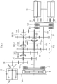
- eine Getriebestruktur eines als Stirnrad-Handschaltgetriebe ausgeführten Hybridgetriebes;
- Figur 2
- in einer Ansicht entsprechend der
Figur 1 ein zweites Ausführungsbeispiel des Hybridgetriebes; und - Figuren 3 und 4
- jeweils eine Abwandlung der
Figur 2 . - In der
Figur 1 ist ein Handschaltgetriebe 1 gezeigt, das Bestandteil eines Hybridantriebsstranges eines nicht dargestellten hybridgetriebenen Kraftfahrzeugs ist. Das mittels Schaltelemente in unterschiedliche Übersetzungsstufen umschaltbare Getriebe 1 ist über eine Brennkraftmaschinen-Welle 3 mit zwischengeschalteter Trennkupplung 4 und Torsionsdämpfer 5 mit einer Brennkraftmaschine 7 verbunden sowie über eine Elektromaschinen-Welle 9 mit einer Elektromaschine 11 verbunden. Die Elektromaschine 11 kann für eine Drehmomentwandlung ein in derFigur 1 dargestelltes Planeten-Vorgelege 12 aufweisen. Zudem ist das Getriebe 1 ausgangsseitig über eine Ausgangswelle 13 mit einer Vorderachse VA des Kraftfahrzeugs trieblich verbunden. Die Ausgangswelle 13 steht als Ritzelwelle mit dem Kegeltrieb eines Vorderachsdifferenzials 15 in Wirkverbindung. - Wie aus der
Figur 1 weiter hervorgeht, sind die Brennkraftmaschinen-Welle 3, die Elektromaschinen-Welle 9 sowie eine zwischengeordnete Abtriebswelle 17 zueinander achsparallel angeordnet. Die Abtriebswelle 17, die Elektromaschinen-Welle 9 sowie die Ausgangswelle 13 sind über Stirnzahnradsätze miteinander trieblich verbindbar, die über die Schaltelemente schaltbar sind. Die Stirnzahnradsätze bilden zueinander parallel angeordnete Radebenen V1 bis V4 und E1 sowie E2, die sich gemäß derFigur 1 in der Axialrichtung allesamt zwischen der Brennkraftmaschine 7 und der Elektromaschine 11 befinden. - Nachfolgend ist die in der
Figur 1 gezeigte Getriebestruktur des Hybridgetriebes 1 beschrieben: So sind in derFigur 1 die Brennkraftmaschinen-Welle 3 und die Abtriebswelle 17 über Radebenen V1 bis V4 miteinander verbunden, die jeweils aus miteinander kämmenden Los- und Festzahnrädern aufgebaut sind. Die Loszahnräder der Radebenen V1 bis V4 sind über Schaltelemente SE-H und SE-G mit der jeweils tragenden Welle 3, 17 koppelbar. Die Radebenen V1 bis V4 sind anbindungsfrei gegenüber der Elektromaschinen-Welle 9. - Zudem sind zwei Hybrid-Radebenen E1, E2 vorgesehen. Jede Hybrid-Radebene E1, E2 weist ein auf der Abtriebswelle 17 angeordnetes abtriebsseitiges Zahnrad 19, 21 auf, das jeweils mit einem auf der Brennkraftmaschinen-Welle 3 angeordneten antriebsseitigen Zahnrad 23, 25 und mit jeweils einem koaxial zur Elektromaschinen-Welle 9 angeordneten (elektromaschinenseitigen) Loszahnrad 27, 29 kämmt. Die antriebsseitige Zahnräder 23, 25 der Hybrid-Radebenen E1, E2 sind als Loszahnräder auf der Brennkraftmaschinen-Welle 3 drehgelagert. Zwischen den elektromaschinenseitigen Loszahnrädern 27, 29 der Hybrid-Radebenen E1, E2 ist ein beidseitig schaltbares Schaltelement SE-A angeordnet, mit dem entweder die erste Hybrid-Radebene E1 oder die zweite Hybrid-Radebene E2 mit der Elektromaschinen-Welle 9 koppelbar ist. Die Abtriebswelle 17 treibt über eine Stirnradstufe St auf die Ausgangswelle 13 ab.
- In der in der
Figur 1 gezeigten Neutralstellung des Schaltelements SE-A ist die Elektromaschinen-Welle 9 vom Antriebsstrang abgekoppelt. Auf diese Weise ist die Elektromaschinen-Welle 9 im Getriebe-Betrieb stillgelegt, d.h. deaktiviert. Dadurch reduziert sich vorteilhaft das Trägheitsmoment des verbleibenden aktivierten Getriebes. Die Zahnräder der Hybrid-Radebenen E1, E2 bleiben jedoch aktiviert, d.h. diese werden trotz stillgelegter Elektromaschine 11 im Getriebe-Betrieb mitgedreht. - In der
Figur 1 sind die beiden Hybrid-Radebenen E1, E2 zu einem gemeinsamen Teilgetriebe T zusammengefasst, das im Getriebe-Betrieb komplett momentenfrei schaltbar ist, das heißt vom Antriebsstrang komplett abkoppelbar ist, so dass das Teilgetriebe T vollständig stillgelegt ist. Zur Realisierung des Teilgetriebes T sind in derFigur 1 die beiden abtriebsseitigen Zahnräder 19, 21 der Hybrid-Radebenen E1, E2 als Loszahnräder auf der Abtriebswelle 17 drehgelagert. Zwischen den beiden abtriebsseitigen Zahnrädern 19, 21 der Hybrid-Radebenen E1 und E2 ist ein Schaltelement SE-B angeordnet, das beidseitig schaltbar ist und entweder die erste oder die zweite Hybrid-Radebene E1, E2 mit der Abtriebswelle koppeln kann. Zudem sind in derFigur 1 die beiden antriebsseitigen Loszahnräder 23, 25 der Hybrid-Radebenen E1, E2 gemeinsam auf einer antriebsseitigen Hohlwelle 31 drehfest angeordnet, die koaxial auf der Brennkraftmaschinen-Welle 3 drehgelagert ist. Die antriebsseitige Hohlwelle 31 ist in bauteilreduzierter Weise über genau ein Schaltelement SE-C mit der Brennkraftmaschinen-Welle 3 koppelbar. - In der
Figur 2 sind im Unterschied zurFigur 1 insgesamt zwei Teilgetriebe T1, T2 bereitgestellt, die im Getriebe-Betrieb jeweils komplett momentenfrei schaltbar sind, das heißt vom Antriebsstrang komplett abkoppelbar sind, so dass das erste Teilgetriebe T1 und/oder das zweite Teilgetriebe T2 vollständig stillgelegt ist. Im ersten Teilgetriebe T1 sind die erste Hybrid-Radebene E1 und eine weitere, unmittelbar axial benachbarte Radebene V4 zusammengefasst. Im zweiten Teilgetriebe T2 sind die zweite Hybrid-Radebene E2 sowie eine unmittelbar benachbarte weitere Radebene V3 miteinander zusammengefasst. - Im ersten Teilgetriebe T1 weist die Radebene V4 ein auf der Abtriebswelle 17 drehgelagertes abtriebsseitiges Loszahnrad 33 auf. Das abtriebsseitige Loszahnrad 33 der Radebene V4 und das abtriebsseitige Loszahnrad 19 der ersten Hybrid-Radebene E1 können über ein dazwischen angeordnetes beidseitig schaltbares Schaltelement SE-D alternierend mit der Abtriebswelle 17 gekoppelt werden. Sowohl die erste Hybrid-Radebene E1 als auch die Radebene V4 weisen auf der Brennkraftmaschinen-Welle 3 drehgelagerte antriebsseitige Loszahnräder 23, 35 auf, die gemeinsam drehfest auf einer antriebsseitigen ersten Hohlwelle 37 angeordnet sind. Diese ist auf der Brennkraftmaschinen-Welle 3 koaxial drehgelagert und über ein Schaltelement SE-F mit der Brennkraftmaschinen-Welle 3 koppelbar.
- Das zweite Teilgetriebe T2 ist baugleich wie das erste Teilgetriebe T1 aufgebaut. Im zweiten Teilgetriebe T2 weist die Radebene V3 ein auf der Abtriebswelle 17 drehgelagertes abtriebsseitiges Loszahnrad 39 auf. Das abtriebsseitige Loszahnrad 39 der Radebene V3 und das abtriebsseitige Loszahnrad 21 der zweiten Hybrid-Radebene E2 können über ein dazwischen angeordnetes beidseitig schaltbares Schaltelement SE-E alternierend mit der Abtriebswelle 17 gekoppelt werden. Sowohl die zweite Hybrid-Radebene E2 als auch die Radebene V3 weisen auf der Brennkraftmaschinen-Welle 3 drehgelagerte antriebsseitige Loszahnräder 25, 41 auf, die gemeinsam drehfest auf einer antriebsseitigen zweiten Hohlwelle 43 angeordnet sind, die auf der Brennkraftmaschinen-Welle 3 koaxial drehgelagert ist und über das Schaltelement SE-F mit der Brennkraftmaschinen-Welle 3 koppelbar ist. Das für die beiden Hohlwellen 37, 43 gemeinsame Schaltelement SE-F ist beidseitig schaltbar und zwischen den beiden antriebsseitigen Hohlwellen 37, 43 angeordnet.
- Wie aus der
Figur 2 weiter hervorgeht, werden die beiden elektromaschinenseitigen Zahnräder 27, 29 der Hybrid-Radebenen E1, E2 über eine Doppelkupplung geschaltet, die aus einer ersten Kupplung K1 und einer zweiten Kupplung K2 aufgebaut ist. Die Doppelkupplung weist einen Außenlamellenträger 45 auf, der drehfest an der Elektromaschinen-Welle 9 angebunden ist. Der Außenlamellenträger 45 wirkt mit zwei in Axialrichtung nebeneinander angeordneten Innenlamellenträger 47, 49 zusammen. Der Innenlamellenträger 49 ist zusammen mit dem elektromaschinenseitigen Zahnrad 27 der ersten Hybrid-Radebene E1 drehfest auf einer Hohlwelle 51 angeordnet. Demgegenüber ist der Innenlamellenträger 47 zusammen mit dem Zahnrad 29 der zweiten Hybrid-Radebene E2 drehfest auf einer Vollwelle 53 angeordnet, die sich koaxial durch die Hohlwelle 51 erstreckt. - Das in der
Figur 2 gezeigte Getriebe 1 weist insgesamt 16 Zahnräder, vier Synchronisierungen sowie zwei Kupplungen K1, K2 auf. In dem Getriebe 1 sind bis zu zehn verbrennungsmotorische Gänge schaltbar, das heißt die nachfolgend erläuterten sechs verbrennungsmotorischen Direkt-Gänge VM1 bis VM6, die lediglich eine Radebene nutzen, sowie die vier Verwindungs-Gänge VM7 bis VM10, die zumindest zwei Radebenen nutzen:
In den Direkt-Gängen VM1 und VM2 ist das Schaltelement SE-H nach links bzw. nach rechts geschaltet, während die beiden Teilgetriebe T1, T2 stillgelegt sind. - Im Direkt-Gang VM3 ist SE-F nach rechts und SE-D nach links geschaltet. Das heißt, dass das Teilgetriebe T1 aktiviert ist und das Teilgetriebe T2 deaktiviert ist. Gleiches trifft auch für den Direkt-Gang VM4 zu, bei dem SE-F nach rechts und SE-D ebenfalls nach rechts geschaltet sind.
- In den folgenden Direkt-Gängen VM5 und VM6 ist das Teilgetriebe T2 aktiviert und das Teilgetriebe T1 deaktiviert. Beim Direkt-Gang VM5 ist SE-F nach links und SE-E nach links geschaltet. Beim Direkt-Gang VM6 ist SE-F nach links und SE-E nach rechts geschaltet.
- Von den folgenden vier verbrennungsmotorischen Verwindungs-Gängen VM7 bis VM10 ist im Gang VM7 das Schaltelement SE-F nach rechts geschaltet, die Kupplungen K1 und K2 betätigt und das Schaltelement SE-E nach links geschaltet. Beim Verwindungs-Gang VM8 sind SE-F nach rechts geschaltet, die beiden Kupplungen K1, K2 betätigt und SE-E nach rechts geschaltet. Im Verwindungs-Gang VM9 sind SE-F nach links geschaltet, die beiden Kupplungen K1, K2 betätigt und SE-D nach links geschaltet. Im Verwindungs-Gang VM10 sind SE-F nach links geschaltet, die beiden Kupplungen K1, K2 betätigt und SE-D nach rechts geschaltet.
- Im rein elektromotorischen Betrieb des in der
Figur 2 gezeigten Getriebes 1 können bis zu 8 elektromotorische Gänge geschaltet werden, das heißt die folgenden zwei Direkt-Gänge EM1, EM2 und die sechs Verwindungs-Gänge EM3 bis EM8:
So ist im Direkt-Gang EM1 die Kupplung K1 betätigt und das Schaltelement SE-D nach links geschaltet. Im Direkt-Gang EM2 ist die Kupplung K2 betätigt und das Schaltelement SE-E nach links geschaltet. Im elektromotorischen Verwindungs-Gang EM3 ist die Kupplung K1 betätigt und SE-D nach rechts geschaltet. Im Verwindungs-Gang EM4 ist die Kupplung K1 betätigt und SE-F nach rechts geschaltet sowie SE-H nach links geschaltet. Im Verwindungs-Gang E5 ist die Kupplung K1 betätigt, SE-F nach rechts geschaltet sowie SE-H nach rechts geschaltet. Im Verwindungs-Gang EM6 ist die Kupplung K2 betätigt sowie SE-E nach rechts geschaltet. Im Verwindungs-Gang EM7 ist die zweite Kupplung K2 betätigt, SE-F nach links geschaltet sowie SE-H nach links geschaltet. Im Verwindungs-Gang EM8 ist die Kupplung K2 betätigt, SE-F nach links geschaltet sowie SE-H nach rechts geschaltet. - Aus den obigen verbrennungsmotorischen Gängen VM1 bis VM10 und den elektromotorischen Gängen EM1 bis EM8 können in Kombination bis zu 28 hybridische Gänge realisiert werden, in denen elektromotorische und verbrennungsmotorische Gänge in Kombination geschaltet sind.
- Nachfolgend sind spezielle Fahrbetriebsarten hervorgehoben, die mittels des in der
Figur 2 gezeigten Getriebes realisierbar sind:
So ist mit der in derFigur 2 gezeigten Getriebestruktur ein Standladen der Elektromaschine 11 ermöglicht, sofern das Fahrzeug im Fahrzeugstillstand ist, zum Beispiel an einer Ampel oder im Stau. In diesem Fall kann beispielhaft das Schaltelement SE-F nach rechts betätigt werden, um die Brennkraftmaschinen-Welle 3 mit der ersten Hybrid-Radebene E1 zu verbinden. Zugleich wird die Kupplung K1 (bestehend aus dem Außenlamellenträger 45 und dem Innenlamellenträger 49) geschlossen, um die erste Hybrid-Radebene E1 mit der Elektromaschinen-Welle 9 zu verbinden. Dadurch ist ein Lastpfad L1 gebildet, der einen Momentenfluss von der Brennkraftmaschine 7 über die Brennkraftmaschinen-Welle 3, die erste Hybrid-Radebene E1, die geschlossene Kupplung K1 bis zur Elektromaschine 11 leitet. - Zudem ist mit Hilfe der Elektromaschine 11 ein Brennkraftmaschinen-Start durchführbar. Die Elektromaschine 11 kann die Brennkraftmaschine 7 über einen Lastpfad L2 starten, bei dem beispielhaft die zweite Kupplung K2 (bestehend aus dem Außenlamellenträger 45 und dem Innenlamellenträger 47) geschlossen ist und das Schaltelement SE-F nach links betätigt ist.
- Ferner kann in der
Figur 2 ein Schaltvorgang zwischen den verbrennungsmotorischen Gängen 1 bis 6 mit Hilfe der Elektromaschine 11 zugkraftunterbrechungsfrei erfolgen, und zwar z.B. mit Hilfe der elektromotorischen Gänge EM1, EM2, die beim verbrennungsmotorischen Schalten als Stützgänge wirken. Ein solcher Schaltvorgang wird mit einem Öffnen der Trennkupplung 4 gestartet, um die Brennkraftmaschine 7 vom Getriebe 1 zu entkoppeln. Ein eingelegter elektromotorischer Stützgang stellt während des zwischen den verbrennungsmotorischen Gängen erfolgenden Schaltvorgangs einen Stützlastpfad bereit, der von der Elektromaschine 11 zur Antriebsseite verläuft. Während des Schaltvorgangs (das heißt die Brennkraftmaschine 7 ist mittels der Trennkupplung 4 vom Antriebsstrang abgekoppelt) kann somit die Elektromaschine 11 ein Antriebsmoment erzeugen, das über den Stütz-Lastpfad zur Abtriebsseite übertragen wird. - Der obige Sachverhalt ist nachfolgend anhand eines zugkraftunterbrechungsfreien Schaltvorgangs zwischen dem dritten und vierten verbrennungsmotorischen Gang erläutert, bei dem der elektromotorische zweite Gang EM2 als Stützgang wirkt: So ist im Getriebe 1 der
Figur 2 im verbrennungsmotorischen dritten Gang VM3 das Schaltelement SE-F nach rechts und das Schaltelement SE-D nach links geschaltet. Dadurch verläuft ein Lastpfad von der Brennkraftmaschine 7, dem Teilgetriebe T1, der Abtriebswelle 17 bis zum abtriebsseitigen Stirnradtrieb St, während das Teilgetriebe T2 deaktiviert (stillgelegt) ist. Zu Beginn des Schaltvorgangs wird die Trennkupplung 4 gelöst und das Schaltelement SE-D in seine Neutralstellung geschaltet. Zudem wird der als Stützgang wirkende elektromotorische Gang EM2 eingelegt, das heißt die Lamellenkupplung K2 geschlossen und das Schaltelement SE-E nach links geschaltet, und die Elektromaschine 11 hochgefahren. Dadurch erfolgt eine Lastübertragung von der Elektromaschine 11 zur Abtriebsseite, bei der die Elektromaschine 11 ein beliebig einstellbares Moment erzeugt. - Der Schaltvorgang in den Zielgang VM4 wird fortgesetzt, indem das Schaltelement SE-D von seiner Neutralstellung nach rechts geschaltet wird. Damit ist ein Lastpfad von der Brennkraftmaschine 7 über das Schaltelement SE-F, die Radebene V4, das Schaltelement SE-D sowie die Abtriebswelle 17 bis zum abtriebsseitigen Stirnradtrieb St vorbereitet. Zum Ende des Schaltvorgangs wird die Trennkupplung 4 wieder geschlossen, das heißt die Brennkraftmaschine 7 zugeschaltet, sowie die Elektromaschine 11 wieder heruntergefahren, so dass der Zielgang VM4 geschaltet ist und abermals eine Lastübertragung von der Brennkraftmaschine 7 zur Abtriebsseite erfolgt.
- Von daher kann im Getriebe 1 der
Figur 2 jede Schaltung mittels eines elektromotorischen Stützgangs gestützt werden, und zwar im Unterschied zurFigur 1 , in der speziell ein Schaltvorgang zwischen dem verbrennungsmotorischen dritten Gang VM3 und dem verbrennungsmotorischen vierten Gang VM4, das heißt zwischen den Hybrid-Radebenen E1 und E2, nicht mittels eines elektromotorischen Gangs gestützt werden kann. In dem in derFigur 1 gezeigten Getriebe 1 kann während des obigen Schaltvorgangs von der Elektromaschine 11 kein Stütz-Lastpfad bereitgestellt werden, da sowohl die Brennkraftmaschine 7 als auch die Elektromaschine 11 über ein gemeinsames Schaltelement SE-B auf die Abtriebswelle 17 abtreiben. Somit ist in derFigur 1 kein zugkraftunterbrechungsfreies Schalten zwischen dem dritten und vierten verbrennungsmotorischen Gang möglich. - Zudem ist mittels des in der
Figur 2 gezeigten Getriebes 1 ein elektromotorisches Anfahren aus dem Fahrzeugstillstand oder ein Boost-Betrieb ermöglicht, bei der für einzelne verbrennungsmotorische Gänge mehrere elektromotorische Gänge zum Boosten zur Verfügung stehen. - Anhand der folgenden
Figuren 3 bis 5 sind Abwandlungen des in derFigur 3 gezeigten Getriebes 1 beschrieben:
So sind in derFigur 3 die beiden elektromaschinenseitigen Zahnräder 27, 29 der Hybrid-Radebenen E1, E2 nicht über eine Doppelkupplung (Figur 2 ) oder über eine Doppelsynchronisierung (Figur 2 ) mit der Elektromaschinen-Welle 9 verbindbar, sondern anstelle dessen mittels einer Freilaufkupplung F und einer Lamellenkupplung K. Die Lamellenkupplung K weist einen Außenlamellenträger 45 auf, der sowohl an der Elektromaschinen-Welle 9 als auch an der Hohlwelle 51 drehfest angebunden ist. Der Außenlamellenträger 45 wirkt auf einen Innenlamellenträger 47. Dieser ist zusammen mit dem Zahnrad 29 der Hybrid-Ebene 1 auf der Vollwelle 53 drehfest angeordnet, die sich koaxial durch die Hohlwelle 51 erstreckt. Das elektromaschinenseitige Zahnrad 27 der ersten Hybridradebene E1 ist über die Freilaufkupplung F mit der Hohlwelle 51 verbindbar. Der Freilaufkupplung F ist ein Schaltelement SE-I zugeordnet, das in zwei Betriebsstellungen schaltbar ist: In der gezeigten Betriebsstellung ist eine Drehmomentübertragung von der Elektromaschinen-Welle 9 über den Außenlamellenträger 45 und über die Hohlwelle 51 in Richtung auf das elektromaschinenseitige Zahnrad 27 der ersten Hybrid-Radebene E1 ermöglicht und in Gegenrichtung die Freilauffunktion aktiviert, das heißt eine Drehmomentübertragung unterbunden. Sofern also die mit der Hohlwelle 51 verbundene Freilaufkupplungs-Innenseite 58 schneller dreht als das elektromaschinenseitige Zahnrad 27, treibt die Hohlwelle 51 das Zahnrad 27 an. In einer zweiten Betriebsstellung ist das Schaltelement SE-I in derFigur 3 nach links geschaltet. In diesem Fall ist eine Drehmomentübertragung in beiden Richtungen ermöglicht. Sowohl in derFigur 3 als auch in derFigur 2 sind die elektromotorischen Gänge lastschaltbar, während in derFigur 1 die elektromotorischen Gänge nicht lastschaltbar sind. - In der
Figur 4 ist die Elektromaschine 11 nicht mehr abtriebsseitig an das Getriebe 1 angebunden (wie in denFiguren 1 bis 3 ), sondern antriebsseitig an das Getriebe 1 angebunden. Bei einer solchen antriebsseitigen Anbindung kämmen die elektromaschinenseitigen Zahnräder 27, 29 der Hybrid-Radebenen E1 und E2 nicht mehr mit den abtriebsseitigen Zahnrädern 19, 21 der Hybrid-Radebenen E1 und E2, sondern mit den antriebsseitigen Zahnrädern 23, 25 der Hybrid-Radebenen E1 und E2. - In den
Figuren 1 bis 4 ist ein elektromotorischer Rückwärtsgang bereitgestellt, bei dem die Elektromaschine 11 in umgekehrter Richtung zu betreiben ist.
Claims (10)
- Hybridantriebsstrang für ein hybridgetriebenes Fahrzeug, mit einem mittels Schaltelemente in unterschiedliche Übersetzungsstufen umschaltbaren Getriebe (1), das über eine Brennkraftmaschinen-Welle (3) mit einer Brennkraftmaschine (7), über eine Elektromaschinen-Welle (9) mit einer Elektromaschine (11) sowie über eine Ausgangswelle (13) mit zumindest einer Fahrzeugachse (VA) trieblich verbindbar ist, wobei die Brennkraftmaschinen-Welle (3) und eine mit der Ausgangswelle (13) trieblich verbundene Abtriebswelle (17) über Stirnzahnradsätze verbindbar sind, die mittels der Schaltelemente schaltbar sind und jeweils Radebenen (V1 bis V4, E1, E2) bilden, wobei die Radebenen (V1 bis V4, E1, E2) eine erste und eine zweite Hybrid-Radebene (E1, E2) aufweisen, die jeweils zusätzlich mit der Elektromaschinen-Welle (9) trieblich verbindbar sind, und wobei die Elektromaschine (11) unter Bildung eines ersten Lastpfads (L1) über die erste Hybrid-Radebene (E1) mit der Brennkraftmaschine (7) verbindbar ist und unter Bildung eines zweiten Lastpfads (L2) über die zweite Hybrid-Radebene (E2) mit der Brennkraftmaschine (7) verbindbar ist, während gleichzeitig die mit der Ausgangswelle (13) verbundene Abtriebswelle (17) vom jeweiligen Lastpfad (L1, L2) entkoppelt ist, wobei die erste und zweite Hybrid-Radebene (E1, E2) jeweils ein auf der Abtriebswelle (17) angeordnetes abtriebsseitiges Zahnrad (19, 21), ein auf der Brennkraftmaschinen-Welle (3) angeordnetes antriebsseitiges Zahnrad (23, 25) und ein zur Elektromaschinen-Welle (9) koaxial angeordnetes elektromaschinenseitiges Zahnrad (27, 29) aufweist, wobei das auf der Abtriebswelle (17) angeordnete abtriebsseitige Zahnrad (19, 21) der ersten und zweiten Hybrid-Radebene (E1, E2) ein Loszahnrad ist, das mittels eines Schaltelements (SE-B) mit der Abtriebswelle (17) koppelbar oder davon abkoppelbar ist, und wobei das auf der Brennkraftmaschinen-Welle (3) angeordnete antriebsseitige Zahnrad (23, 25) der ersten und zweiten Hybrid-Radebene (E1, E2) ein Loszahnrad ist, das mittels eines Schaltelements (SE-C) mit der Brennkraftmaschinen-Welle (3) koppelbar ist, dadurch gekennzeichnet, dass das elektromaschinenseitige Zahnrad (27, 29) als Loszahnrad drehgelagert ist und mittels einem Schaltelement (SE-A) von der Elektromaschinen-Welle (9) abkoppelbar ist oder damit koppelbar ist, und dass die beiden Hybrid-Radebenen (E1, E2) Bestandteile eines gemeinsamen Teilgetriebes (T) sind, das während des Getriebe-Betriebs stilllegbar ist, das heißt von der Brennkraftmaschine (7) und von der Abtriebsseite abkoppelbar ist, und dass im Teilgetriebe (T) die auf der Brennkraftmaschinen-Welle (3) angeordneten antriebsseitigen Loszahnräder (23, 25) der beiden Hybridradebenen (E1, E2) gemeinsam auf einer Hohlwelle (31) drehfest angeordnet sind, die koaxial auf der Brennkraftmaschinen-Welle (3) drehgelagert ist und über genau ein Schaltelement (SE-C) mit der Brennkraftmaschinen-Welle (3) koppelbar ist.
- Antriebsstrang nach Anspruch 1, dadurch gekennzeichnet, dass das auf der Elektromaschinen-Welle (9) angeordnete Schaltelement (SE-A) beidseitig schaltbar ist und in Axialrichtung zwischen den elektromaschinenseitigen Loszahnrädern (27, 29) der beiden Hybrid-Radebenen (E1, E2) angeordnet ist, wobei das Schaltelement (SE-A) in einer Neutralstellung von den beiden Hybrid-Radebenen (E1, E2) abgekoppelt ist und das Schaltelement (SE-A) entweder in einer ersten Schaltstellung das Loszahnrad (27) der ersten Hybrid-Radebene (E1) mit der Elektromaschinen-Welle (9) koppelt oder in einer zweiten Schaltstellung das Loszahnrad (29) der zweiten Hybrid-Radebene (E2) mit der Elektromaschinen-Welle (9) koppelt.
- Antriebsstrang nach einem der Ansprüche 1 oder 2, dadurch gekennzeichnet, dass die Elektromaschinen-Welle (9) frei von drehfest darauf angeordneten Festzahnräder der die Radebenen bildenden Stirnzahnradsätze ist.
- Antriebsstrang nach einem der vorhergehenden Ansprüche, dadurch gekennzeichnet, dass die Abtriebswelle (17) über eine Stirnradstufe (St) mit der Ausgangswelle (13) verbunden ist, und dass sämtliche Radebenen (V1 bis V4, E1, E2) in der Axialrichtung zwischen der Stirnradstufe (St) und der Elektromaschine (11) angeordnet sind, und/oder dass die erste und zweite Hybrid-Radebene (E1, E2) unmittelbar axial benachbart an der Elektromaschine (11) angeordnet sind.
- Antriebsstrang nach einem der vorhergehenden Ansprüche, dadurch gekennzeichnet, dass das auf der Abtriebswelle (17) angeordnete Schaltelement (SE-B) beidseitig schaltbar ist und in Axialrichtung zwischen den abtriebsseitigen Loszahnrädern (19, 21) der beiden Hybrid-Radebenen (E1, E2) angeordnet ist, wobei das Schaltelement (SE-B) entweder in einer ersten Schaltstellung das abtriebsseitige Loszahnrad (19) der ersten Hybrid-Radebene (E1) mit der Abtriebswelle (17) koppelt oder in einer zweiten Schaltstellung das abtriebsseitige Loszahnrad (21) der zweiten Hybrid-Radebene (E2) mit der Abtriebswelle (17) koppelt.
- Hybridantriebsstrang für ein hybridgetriebenes Fahrzeug, mit einem mittels Schaltelemente in unterschiedliche Übersetzungsstufen umschaltbaren Getriebe (1), das über eine Brennkraftmaschinen-Welle (3) mit einer Brennkraftmaschine (7), über eine Elektromaschinen-Welle (9) mit einer Elektromaschine (11) sowie über eine Ausgangswelle (13) mit zumindest einer Fahrzeugachse (VA) trieblich verbindbar ist, wobei die Brennkraftmaschinen-Welle (3) und eine mit der Ausgangswelle (13) trieblich verbundene Abtriebswelle (17) über Stirnzahnradsätze verbindbar sind, die mittels der Schaltelemente schaltbar sind und jeweils Radebenen (V1 bis V4, E1, E2) bilden, wobei die Radebenen (V1 bis V4, E1, E2) eine erste und eine zweite Hybrid-Radebene (E1, E2) aufweisen, die jeweils zusätzlich mit der Elektromaschinen-Welle (9) trieblich verbindbar sind, und wobei die Elektromaschine (11) unter Bildung eines ersten Lastpfads (L1) über die erste Hybrid-Radebene (E1) mit der Brennkraftmaschine (7) verbindbar ist und unter Bildung eines zweiten Lastpfads (L2) über die zweite Hybrid-Radebene (E2) mit der Brennkraftmaschine (7) verbindbar ist, während gleichzeitig die mit der Ausgangswelle (13) verbundene Abtriebswelle (17) vom jeweiligen Lastpfad (L1, L2) entkoppelt ist, wobei die erste und zweite Hybrid-Radebene (E1, E2) jeweils ein auf der Abtriebswelle (17) angeordnetes abtriebsseitiges Zahnrad (19, 21), ein auf der Brennkraftmaschinen-Welle (3) angeordnetes antriebsseitiges Zahnrad (23, 25) und ein zur Elektromaschinen-Welle (9) koaxial angeordnetes elektromaschinenseitiges Zahnrad (27, 29) aufweist, wobei das auf der Abtriebswelle (17) angeordnete abtriebsseitige Zahnrad (19, 21) der ersten und zweiten Hybrid-Radebene (E1, E2) ein Loszahnrad ist, und wobei das auf der Brennkraftmaschinen-Welle (3) angeordnete antriebsseitige Zahnrad (23, 25) der ersten und zweiten Hybrid-Radebene (E1, E2) ein Loszahnrad ist, dadurch gekennzeichnet, dass das elektromaschinenseitige Zahnrad (27, 29) als Loszahnrad drehgelagert ist und mittels einem Schaltelement (K1, K2; K, F) von der Elektromaschinen-Welle (9) abkoppelbar ist oder damit koppelbar ist, dass jeder Hybrid-Radebene (E1, E2) jeweils eine weitere Radebene (V3, V4) unmittelbar benachbart ist, die gegenüber der Elektromaschinen-Welle (9) anbindungsfrei ist und ein auf der Abtriebswelle (17) drehgelagertes abtriebsseitiges Loszahnrad (33, 39) aufweist, das mittels eines Schaltelements (SE-D, SE-E) mit der Abtriebswelle (17) koppelbar ist, und dass das auf der Abtriebswelle (17) angeordnete Schaltelement (SE-D, SE-E) beidseitig schaltbar ist und in Axialrichtung zwischen den auf der Abtriebswelle (17) drehgelagerten abtriebsseitigen Loszahnrädern (19, 21, 33, 39) der jeweiligen Hybrid-Radebene (E1, E2) und der zugeordneten weiteren Radebene (V3, V4) angeordnet ist, wobei das Schaltelement (SE-D, SE-E) in einer Neutralstellung von der Hybrid-Radebene (E1, E2) und von der weiteren Radebene (V3, V4) abgekoppelt ist und das Schaltelement (SE-D, SE-E) entweder in einer ersten Schaltstellung das abtriebsseitige Loszahnrad (33, 39) der weiteren Radebene (V3, V4) mit der Abtriebswelle (17) koppelt oder in einer zweiten Schaltstellung das abtriebsseitige Loszahnrad (19, 21) der Hybrid-Radebene (E1, E2) mit der Abtriebswelle (17) koppelt, und dass die erste Hybrid-Radebene (E1) mit der zugeordneten weiteren Radebene (V4) ein erstes Teilgetriebe (T1) bildet, und dass die zweite Hybrid-Radebene (E2) mit der zugeordneten weiteren Radebene (V3) ein zweites Teilgetriebe (T2) bildet, und dass die Teilgetriebe (T1, T2) während des Getriebe-Betriebs stilllegbar sind, das heißt vom Antriebsstrang abkoppelbar ist, und dass in jedem der Teilgetriebe (T1, T2) die weitere Radebene (V3, V4) ein auf der Brennkraftmaschinen-Welle (3) drehgelagertes antriebsseitiges Loszahnrad (35, 41) aufweist, das mittels eines Schaltelements (SE-F) mit der Brennkraftmaschinen-Welle (3) koppelbar ist, und dass die auf der Brennkraftmaschinen-Welle (3) drehgelagerten Loszahnräder (35, 41, 23, 25) der Hybrid-Radebene (E1, E2) und der weiteren Radebene (V3, V4) auf jeweils einer abtriebsseitigen Hohlwelle (37, 43) drehfest angeordnet sind, die auf der Brennkraftmaschinen-Welle (3) koaxial drehgelagert ist und über genau ein Schaltelement (SE-F) mit der Brennkraftmaschinen-Welle (3) koppelbar ist.
- Antriebsstrang nach Anspruch 6, dadurch gekennzeichnet, dass das auf der Brennkraftmaschinen-Welle (3) angeordnete Schaltelement (SE-F) beidseitig schaltbar ist und in Axialrichtung zwischen den antriebsseitigen Hohlwellen (37, 43) der beiden Teilgetriebe (T1, T2) angeordnet ist, wobei das Schaltelement (SE-F) in einer Neutralstellung von beiden Hohlwellen (37, 43) abgekoppelt ist und das Schaltelement (SE-F) entweder in einer ersten Schaltstellung die antriebsseitige Hohlwelle (37) des ersten Teilgetriebes (T1) mit der Brennkraftmaschinen-Welle (3) koppelt oder in einer zweiten Schaltstellung die antriebsseitige Hohlwelle (43) des zweiten Teilgetriebes (T2) mit der Brennkraftmaschinen-Welle (3) koppelt.
- Antriebsstrang nach einem der vorhergehenden Ansprüche, dadurch gekennzeichnet, dass die Elektromaschinen-Welle (9) über ein erstes Schaltelement (F; K1) mit der ersten Hybridebene (E1) und mit einem zweiten Schaltelement (K; K2) mit der zweiten Hybridebene (E2) verbunden ist.
- Antriebsstrang nach Anspruch 8, dadurch gekennzeichnet, dass das elektromaschinenseitige Zahnrad (27) der ersten Hybridebene (E1) auf einer zur Elektromaschinen-Welle (9) koaxialen Hohlwelle (51), drehfest angeordnet, ist, und dass die Hohlwelle (51) über das erste Schaltelement (K1) mit der Elektromaschinen-Welle (9) verbindbar ist, und dass das Zahnrad (29) der zweiten Hybridebene (E2) auf einer koaxial durch die Hohlwelle (51) geführten Vollwelle (53) drehfest angeordnet ist, und dass die Vollwelle (53) über das zweite Schaltelement (K2; K), mit der Elektromaschinen-Welle (9) verbindbar ist.
- Antriebsstrang nach einem der Ansprüche 8 oder 9, dadurch gekennzeichnet, dass das zweite Schaltelement eine Kupplung (K) ist, mit der die Vollwelle (53) mit der Elektromaschinen-Welle (9) verbindbar ist, wobei der Außenlamellenträger (45) der Kupplung (K) sowohl an der Elektromaschinen-Welle (9) als auch an der Hohlwelle (51) fest angebunden ist.
Applications Claiming Priority (2)
| Application Number | Priority Date | Filing Date | Title |
|---|---|---|---|
| DE102016221060.2A DE102016221060A1 (de) | 2016-10-26 | 2016-10-26 | Hybridantriebsstrang für ein hybridgetriebenes Kraftfahrzeug |
| PCT/EP2017/077206 WO2018077904A1 (de) | 2016-10-26 | 2017-10-24 | Hybridantriebsstrang für ein hybridgetriebenes kraftfahrzeug |
Publications (2)
| Publication Number | Publication Date |
|---|---|
| EP3532327A1 EP3532327A1 (de) | 2019-09-04 |
| EP3532327B1 true EP3532327B1 (de) | 2022-02-23 |
Family
ID=60190832
Family Applications (1)
| Application Number | Title | Priority Date | Filing Date |
|---|---|---|---|
| EP17791343.1A Active EP3532327B1 (de) | 2016-10-26 | 2017-10-24 | Hybridantriebsstrang für ein hybridgetriebenes kraftfahrzeug |
Country Status (5)
| Country | Link |
|---|---|
| US (1) | US10882387B2 (de) |
| EP (1) | EP3532327B1 (de) |
| CN (1) | CN109863055B (de) |
| DE (1) | DE102016221060A1 (de) |
| WO (1) | WO2018077904A1 (de) |
Families Citing this family (21)
| Publication number | Priority date | Publication date | Assignee | Title |
|---|---|---|---|---|
| DE102016204586B4 (de) * | 2016-03-18 | 2022-02-03 | Audi Ag | Hybridantriebsstrang für ein hybridgetriebenes Kraftfahrzeug |
| DE102016221057B4 (de) * | 2016-10-26 | 2024-06-13 | Audi Ag | Hybridantriebsstrang für ein hybridgetriebenes Kraftfahrzeug |
| DE102017215674A1 (de) * | 2017-09-06 | 2019-03-07 | Audi Ag | Hybridantriebsstrang für ein hybridgetriebenes Kraftfahrzeug |
| KR102497028B1 (ko) * | 2017-11-24 | 2023-02-08 | 현대자동차주식회사 | 자동화 수동변속기 |
| DE102019211562A1 (de) * | 2019-08-01 | 2021-02-04 | Ford Global Technologies, Llc | Hybridantriebsstrang für ein Kraftfahrzeug |
| DE102020131921B4 (de) | 2020-12-02 | 2024-10-17 | Audi Aktiengesellschaft | Hybridantriebsstrang für ein hybridgetriebenes Fahrzeug |
| DE102020131919A1 (de) | 2020-12-02 | 2022-06-02 | Audi Aktiengesellschaft | Hybridantriebsstrang für ein hybridgetriebenes Fahrzeug |
| DE102020131920B4 (de) | 2020-12-02 | 2024-10-17 | Audi Aktiengesellschaft | Hybridantriebsstrang für ein hybridgetriebenes Fahrzeug |
| DE102020131904B4 (de) | 2020-12-02 | 2024-06-13 | Audi Aktiengesellschaft | Hybridantriebsstrang für ein hybridgetriebenes Fahrzeug |
| DE102020131911B4 (de) | 2020-12-02 | 2024-06-13 | Audi Aktiengesellschaft | Hybridantriebsstrang für ein hybridgetriebenes Fahrzeug |
| DE102020131917B4 (de) | 2020-12-02 | 2024-10-17 | Audi Aktiengesellschaft | Hybridantriebsstrang für ein hybridgetriebenes Fahrzeug |
| DE102020131916B4 (de) | 2020-12-02 | 2024-06-13 | Audi Aktiengesellschaft | Hybridantriebsstrang für ein hybridgetriebenes Fahrzeug |
| DE102020131913B4 (de) | 2020-12-02 | 2024-06-13 | Audi Aktiengesellschaft | Hybridantriebsstrang für ein hybridgetriebenes Fahrzeug |
| DE102020131906B4 (de) | 2020-12-02 | 2024-06-13 | Audi Aktiengesellschaft | Hybridantriebsstrang für ein hybridgetriebenes Fahrzeug |
| DE102020131903B4 (de) | 2020-12-02 | 2024-10-17 | Audi Aktiengesellschaft | Hybridantriebsstrang für ein hybridgetriebenes Fahrzeug |
| DE102020131912B4 (de) | 2020-12-02 | 2024-10-17 | Audi Aktiengesellschaft | Hybridantriebsstrang für ein hybridgetriebenes Fahrzeug |
| DE102020131914B4 (de) | 2020-12-02 | 2024-06-13 | Audi Aktiengesellschaft | Hybridantriebsstrang für ein hybridgetriebenes Fahrzeug |
| DE102020131905B4 (de) | 2020-12-02 | 2024-06-13 | Audi Aktiengesellschaft | Hybridantriebsstrang für ein hybridgetriebenes Fahrzeug |
| DE102020131915B4 (de) | 2020-12-02 | 2024-03-28 | Audi Aktiengesellschaft | Hybridantriebsstrang für ein hybridgetriebenes Fahrzeug |
| DE102020131909B4 (de) | 2020-12-02 | 2024-06-13 | Audi Aktiengesellschaft | Hybridantriebsstrang für ein hybridgetriebenes Fahrzeug |
| DE102020131908A1 (de) | 2020-12-02 | 2022-06-02 | Audi Aktiengesellschaft | Hybridantriebsstrang für ein hybridgetriebenes Fahrzeug |
Family Cites Families (29)
| Publication number | Priority date | Publication date | Assignee | Title |
|---|---|---|---|---|
| DE19745995A1 (de) * | 1997-03-11 | 1998-09-17 | Bosch Gmbh Robert | Getriebeintegrierte Elektromaschine für Kraftfahrzeug-Brennkraftmaschinen und deren Steuerung |
| DE10165097B3 (de) * | 2000-07-18 | 2015-07-23 | Schaeffler Technologies AG & Co. KG | Doppelkupplungsgetriebe |
| DE10136725B4 (de) * | 2000-07-28 | 2016-09-15 | Aisin Seiki K.K. | Leistungsübertragungsvorrichtung für ein Hybridfahrzeug |
| FR2821137B1 (fr) | 2001-02-19 | 2004-05-28 | Peugeot Citroen Automobiles Sa | Systeme de transmission de mouvement pour vehicules a propulsion hybride |
| JP4445185B2 (ja) * | 2002-06-28 | 2010-04-07 | アイシン精機株式会社 | 車両用動力伝達装置 |
| DE102004050757A1 (de) * | 2004-10-16 | 2006-04-27 | Daimlerchrysler Ag | Satz von Getrieben und Hybrid-Doppelkupplungsgetriebe |
| DE102006036758B4 (de) * | 2006-08-05 | 2015-03-12 | Zf Friedrichshafen Ag | Automatisiertes Doppelkupplungsgetriebe eines Kraftfahrzeuges |
| EP2144777B1 (de) * | 2007-05-14 | 2017-03-01 | FEV GmbH | Verfahren zum betrieb eines hybridantriebssystems sowie hybridantriebssystem mit zwei teilgetrieben |
| WO2009034877A1 (ja) | 2007-09-10 | 2009-03-19 | Toyota Jidosha Kabushiki Kaisha | 車両用充電装置および車両の充電方法 |
| FR2922821B1 (fr) * | 2007-10-24 | 2011-12-16 | Thierry Zerbato | Dispositif d'accouplement pour une motorisation hybride a fonctionnement selon au moins deux modes electrique/ thermique-electrique destinee a un vehicule. |
| US8224514B2 (en) | 2007-11-03 | 2012-07-17 | GM Global Technology Operations LLC | Creation and depletion of short term power capability in a hybrid electric vehicle |
| DE102008031456B4 (de) | 2008-07-05 | 2021-05-27 | EGS Entwicklungsgesellschaft für Getriebesysteme mbH | Lastschaltgetriebe |
| JP5185065B2 (ja) | 2008-10-23 | 2013-04-17 | トヨタ自動車株式会社 | 制御装置及び制御方法 |
| WO2011002921A2 (en) | 2009-07-01 | 2011-01-06 | Johnson Controls - Saft Advanced Power Solutions Llc | Battery system with improved thermal management system |
| DE102010028026B4 (de) * | 2010-04-21 | 2025-04-17 | Zf Friedrichshafen Ag | Hybridantriebsstrang und Verfahren zum Betreiben eines Hybridantriebsstranges |
| DE102011101151A1 (de) | 2010-05-25 | 2011-12-01 | Schaeffler Technologies Gmbh & Co. Kg | Antriebsstrang mit einem Kupplungsaggregat nach Art einer Doppelkupplung und einem Freilauf |
| DE102010030573A1 (de) * | 2010-06-28 | 2011-12-29 | Zf Friedrichshafen Ag | Hybridantrieb mit einem automatisierten Schaltgetriebe |
| DE102010030567B4 (de) | 2010-06-28 | 2024-02-29 | Zf Friedrichshafen Ag | Hybridantrieb eines Kraftfahrzeugs und Verfahren zum Betreiben desselben |
| DE102010063092A1 (de) * | 2010-12-15 | 2011-06-30 | Bayerische Motoren Werke Aktiengesellschaft, 80809 | Hybridantrieb |
| JP5876242B2 (ja) * | 2011-07-19 | 2016-03-02 | アイシン・エーアイ株式会社 | 手動変速機 |
| WO2013111258A1 (ja) | 2012-01-23 | 2013-08-01 | トヨタ自動車株式会社 | 車両および車両用制御方法 |
| DE102012009484B3 (de) * | 2012-05-09 | 2013-09-12 | Getrag Getriebe- Und Zahnradfabrik Hermann Hagenmeyer Gmbh & Cie Kg | Doppelkupplungsgetriebe |
| DE102012016990A1 (de) * | 2012-07-02 | 2014-01-02 | Volkswagen Aktiengesellschaft | Hybridantriebsstrang für ein Kraftfahrzeug, Hybridfahrzeug und Verwendung desselben |
| GB2506601A (en) * | 2012-10-02 | 2014-04-09 | Gm Global Tech Operations Inc | A four gear double clutch gearbox with electric motor synchronization |
| DE102013005252A1 (de) | 2013-03-27 | 2014-10-02 | Getrag Getriebe- Und Zahnradfabrik Hermann Hagenmeyer Gmbh & Cie Kg | Hybrid-Antriebsstrang und Verfahren zum Steuern desselben |
| DE102013206176A1 (de) | 2013-04-09 | 2014-10-09 | Magna Powertrain Ag & Co. Kg | Fahrzeugantrieb |
| DE102013210013A1 (de) * | 2013-05-29 | 2014-12-04 | Schaeffler Technologies Gmbh & Co. Kg | Verfahren zum Schalten eines Antriebsstrang für ein Fahrzeug sowie Antriebsstrang |
| JP5991336B2 (ja) | 2014-03-18 | 2016-09-14 | トヨタ自動車株式会社 | ハイブリッド車両およびその制御方法 |
| DE102014013579A1 (de) | 2014-09-13 | 2015-03-19 | Daimler Ag | Antriebsstrangvorrichtung für ein Hybridfahrzeug |
-
2016
- 2016-10-26 DE DE102016221060.2A patent/DE102016221060A1/de not_active Withdrawn
-
2017
- 2017-10-24 CN CN201780066134.5A patent/CN109863055B/zh active Active
- 2017-10-24 EP EP17791343.1A patent/EP3532327B1/de active Active
- 2017-10-24 US US16/343,844 patent/US10882387B2/en active Active
- 2017-10-24 WO PCT/EP2017/077206 patent/WO2018077904A1/de not_active Ceased
Also Published As
| Publication number | Publication date |
|---|---|
| CN109863055A (zh) | 2019-06-07 |
| CN109863055B (zh) | 2022-03-25 |
| DE102016221060A1 (de) | 2018-04-26 |
| EP3532327A1 (de) | 2019-09-04 |
| US20190263247A1 (en) | 2019-08-29 |
| WO2018077904A1 (de) | 2018-05-03 |
| US10882387B2 (en) | 2021-01-05 |
Similar Documents
| Publication | Publication Date | Title |
|---|---|---|
| EP3532327B1 (de) | Hybridantriebsstrang für ein hybridgetriebenes kraftfahrzeug | |
| EP3429879B1 (de) | Hybridantriebsstrang für ein hybridgetriebenes kraftfahrzeug | |
| DE102016221061B4 (de) | Hybridantriebsstrang für ein hybridgetriebenes Kraftfahrzeug | |
| EP3615366B1 (de) | Hybridantriebsstrang für ein kraftfahrzeug | |
| DE102016221057B4 (de) | Hybridantriebsstrang für ein hybridgetriebenes Kraftfahrzeug | |
| DE102016221058B4 (de) | Hybridantriebsstrang für ein hybridgetriebenes Kraftfahrzeug | |
| WO2018077902A1 (de) | Hybridantriebsstrang für ein hybridgetriebenes kraftfahrzeug | |
| DE102021211242B4 (de) | Hybrid-Getriebeanordnung und Hybrid-Antriebsstrang | |
| DE102016204580B4 (de) | Hybridantriebsstrang für ein hybridgetriebenes Kraftfahrzeug | |
| DE102021202250B4 (de) | Hybrid-Getriebeanordnung und Fahrzeug mit einer Hybrid-Getriebeanordnung | |
| DE102020131903B4 (de) | Hybridantriebsstrang für ein hybridgetriebenes Fahrzeug | |
| DE102016204582A1 (de) | Hybridantriebsstrang für ein hybridgetriebenes Kraftfahrzeug | |
| DE102020131904A1 (de) | Hybridantriebsstrang für ein hybridgetriebenes Fahrzeug | |
| DE102020131917B4 (de) | Hybridantriebsstrang für ein hybridgetriebenes Fahrzeug | |
| DE102021202252B4 (de) | Hybrid-Getriebeanordnung und Fahrzeug mit einer Hybrid-Getriebeanordnung | |
| DE102020131911B4 (de) | Hybridantriebsstrang für ein hybridgetriebenes Fahrzeug | |
| DE102020131921B4 (de) | Hybridantriebsstrang für ein hybridgetriebenes Fahrzeug | |
| DE102020131915B4 (de) | Hybridantriebsstrang für ein hybridgetriebenes Fahrzeug | |
| DE102020131920B4 (de) | Hybridantriebsstrang für ein hybridgetriebenes Fahrzeug | |
| DE102011081760A1 (de) | Antriebsanordnung einer mobilen Arbeitsmaschine | |
| DE102016204581A1 (de) | Hybridantriebsstrang für ein hybridgetriebenes Kraftfahrzeug | |
| DE102016204584A1 (de) | Hybridantriebsstrang für ein hybridgetriebenes Kraftfahrzeug | |
| DE102020131919A1 (de) | Hybridantriebsstrang für ein hybridgetriebenes Fahrzeug | |
| DE102020131906A1 (de) | Hybridantriebsstrang für ein hybridgetriebenes Fahrzeug | |
| DE102021205932A1 (de) | Getriebe und Antriebsstrang für ein Kraftfahrzeug |
Legal Events
| Date | Code | Title | Description |
|---|---|---|---|
| STAA | Information on the status of an ep patent application or granted ep patent |
Free format text: STATUS: UNKNOWN |
|
| STAA | Information on the status of an ep patent application or granted ep patent |
Free format text: STATUS: THE INTERNATIONAL PUBLICATION HAS BEEN MADE |
|
| PUAI | Public reference made under article 153(3) epc to a published international application that has entered the european phase |
Free format text: ORIGINAL CODE: 0009012 |
|
| STAA | Information on the status of an ep patent application or granted ep patent |
Free format text: STATUS: REQUEST FOR EXAMINATION WAS MADE |
|
| 17P | Request for examination filed |
Effective date: 20190527 |
|
| AK | Designated contracting states |
Kind code of ref document: A1 Designated state(s): AL AT BE BG CH CY CZ DE DK EE ES FI FR GB GR HR HU IE IS IT LI LT LU LV MC MK MT NL NO PL PT RO RS SE SI SK SM TR |
|
| AX | Request for extension of the european patent |
Extension state: BA ME |
|
| DAV | Request for validation of the european patent (deleted) | ||
| DAX | Request for extension of the european patent (deleted) | ||
| GRAP | Despatch of communication of intention to grant a patent |
Free format text: ORIGINAL CODE: EPIDOSNIGR1 |
|
| STAA | Information on the status of an ep patent application or granted ep patent |
Free format text: STATUS: GRANT OF PATENT IS INTENDED |
|
| INTG | Intention to grant announced |
Effective date: 20211014 |
|
| GRAS | Grant fee paid |
Free format text: ORIGINAL CODE: EPIDOSNIGR3 |
|
| GRAA | (expected) grant |
Free format text: ORIGINAL CODE: 0009210 |
|
| STAA | Information on the status of an ep patent application or granted ep patent |
Free format text: STATUS: THE PATENT HAS BEEN GRANTED |
|
| AK | Designated contracting states |
Kind code of ref document: B1 Designated state(s): AL AT BE BG CH CY CZ DE DK EE ES FI FR GB GR HR HU IE IS IT LI LT LU LV MC MK MT NL NO PL PT RO RS SE SI SK SM TR |
|
| REG | Reference to a national code |
Ref country code: GB Ref legal event code: FG4D Free format text: NOT ENGLISH |
|
| REG | Reference to a national code |
Ref country code: CH Ref legal event code: EP |
|
| REG | Reference to a national code |
Ref country code: DE Ref legal event code: R096 Ref document number: 502017012656 Country of ref document: DE |
|
| REG | Reference to a national code |
Ref country code: AT Ref legal event code: REF Ref document number: 1470199 Country of ref document: AT Kind code of ref document: T Effective date: 20220315 |
|
| REG | Reference to a national code |
Ref country code: IE Ref legal event code: FG4D Free format text: LANGUAGE OF EP DOCUMENT: GERMAN |
|
| REG | Reference to a national code |
Ref country code: LT Ref legal event code: MG9D |
|
| REG | Reference to a national code |
Ref country code: NL Ref legal event code: MP Effective date: 20220223 |
|
| PG25 | Lapsed in a contracting state [announced via postgrant information from national office to epo] |
Ref country code: SE Free format text: LAPSE BECAUSE OF FAILURE TO SUBMIT A TRANSLATION OF THE DESCRIPTION OR TO PAY THE FEE WITHIN THE PRESCRIBED TIME-LIMIT Effective date: 20220223 Ref country code: RS Free format text: LAPSE BECAUSE OF FAILURE TO SUBMIT A TRANSLATION OF THE DESCRIPTION OR TO PAY THE FEE WITHIN THE PRESCRIBED TIME-LIMIT Effective date: 20220223 Ref country code: PT Free format text: LAPSE BECAUSE OF FAILURE TO SUBMIT A TRANSLATION OF THE DESCRIPTION OR TO PAY THE FEE WITHIN THE PRESCRIBED TIME-LIMIT Effective date: 20220623 Ref country code: NO Free format text: LAPSE BECAUSE OF FAILURE TO SUBMIT A TRANSLATION OF THE DESCRIPTION OR TO PAY THE FEE WITHIN THE PRESCRIBED TIME-LIMIT Effective date: 20220523 Ref country code: NL Free format text: LAPSE BECAUSE OF FAILURE TO SUBMIT A TRANSLATION OF THE DESCRIPTION OR TO PAY THE FEE WITHIN THE PRESCRIBED TIME-LIMIT Effective date: 20220223 Ref country code: LT Free format text: LAPSE BECAUSE OF FAILURE TO SUBMIT A TRANSLATION OF THE DESCRIPTION OR TO PAY THE FEE WITHIN THE PRESCRIBED TIME-LIMIT Effective date: 20220223 Ref country code: HR Free format text: LAPSE BECAUSE OF FAILURE TO SUBMIT A TRANSLATION OF THE DESCRIPTION OR TO PAY THE FEE WITHIN THE PRESCRIBED TIME-LIMIT Effective date: 20220223 Ref country code: ES Free format text: LAPSE BECAUSE OF FAILURE TO SUBMIT A TRANSLATION OF THE DESCRIPTION OR TO PAY THE FEE WITHIN THE PRESCRIBED TIME-LIMIT Effective date: 20220223 Ref country code: BG Free format text: LAPSE BECAUSE OF FAILURE TO SUBMIT A TRANSLATION OF THE DESCRIPTION OR TO PAY THE FEE WITHIN THE PRESCRIBED TIME-LIMIT Effective date: 20220523 |
|
| PG25 | Lapsed in a contracting state [announced via postgrant information from national office to epo] |
Ref country code: PL Free format text: LAPSE BECAUSE OF FAILURE TO SUBMIT A TRANSLATION OF THE DESCRIPTION OR TO PAY THE FEE WITHIN THE PRESCRIBED TIME-LIMIT Effective date: 20220223 Ref country code: LV Free format text: LAPSE BECAUSE OF FAILURE TO SUBMIT A TRANSLATION OF THE DESCRIPTION OR TO PAY THE FEE WITHIN THE PRESCRIBED TIME-LIMIT Effective date: 20220223 Ref country code: GR Free format text: LAPSE BECAUSE OF FAILURE TO SUBMIT A TRANSLATION OF THE DESCRIPTION OR TO PAY THE FEE WITHIN THE PRESCRIBED TIME-LIMIT Effective date: 20220524 Ref country code: FI Free format text: LAPSE BECAUSE OF FAILURE TO SUBMIT A TRANSLATION OF THE DESCRIPTION OR TO PAY THE FEE WITHIN THE PRESCRIBED TIME-LIMIT Effective date: 20220223 |
|
| PG25 | Lapsed in a contracting state [announced via postgrant information from national office to epo] |
Ref country code: IS Free format text: LAPSE BECAUSE OF FAILURE TO SUBMIT A TRANSLATION OF THE DESCRIPTION OR TO PAY THE FEE WITHIN THE PRESCRIBED TIME-LIMIT Effective date: 20220623 |
|
| PG25 | Lapsed in a contracting state [announced via postgrant information from national office to epo] |
Ref country code: SM Free format text: LAPSE BECAUSE OF FAILURE TO SUBMIT A TRANSLATION OF THE DESCRIPTION OR TO PAY THE FEE WITHIN THE PRESCRIBED TIME-LIMIT Effective date: 20220223 Ref country code: SK Free format text: LAPSE BECAUSE OF FAILURE TO SUBMIT A TRANSLATION OF THE DESCRIPTION OR TO PAY THE FEE WITHIN THE PRESCRIBED TIME-LIMIT Effective date: 20220223 Ref country code: RO Free format text: LAPSE BECAUSE OF FAILURE TO SUBMIT A TRANSLATION OF THE DESCRIPTION OR TO PAY THE FEE WITHIN THE PRESCRIBED TIME-LIMIT Effective date: 20220223 Ref country code: EE Free format text: LAPSE BECAUSE OF FAILURE TO SUBMIT A TRANSLATION OF THE DESCRIPTION OR TO PAY THE FEE WITHIN THE PRESCRIBED TIME-LIMIT Effective date: 20220223 Ref country code: DK Free format text: LAPSE BECAUSE OF FAILURE TO SUBMIT A TRANSLATION OF THE DESCRIPTION OR TO PAY THE FEE WITHIN THE PRESCRIBED TIME-LIMIT Effective date: 20220223 Ref country code: CZ Free format text: LAPSE BECAUSE OF FAILURE TO SUBMIT A TRANSLATION OF THE DESCRIPTION OR TO PAY THE FEE WITHIN THE PRESCRIBED TIME-LIMIT Effective date: 20220223 |
|
| REG | Reference to a national code |
Ref country code: DE Ref legal event code: R097 Ref document number: 502017012656 Country of ref document: DE |
|
| PG25 | Lapsed in a contracting state [announced via postgrant information from national office to epo] |
Ref country code: AL Free format text: LAPSE BECAUSE OF FAILURE TO SUBMIT A TRANSLATION OF THE DESCRIPTION OR TO PAY THE FEE WITHIN THE PRESCRIBED TIME-LIMIT Effective date: 20220223 |
|
| PLBE | No opposition filed within time limit |
Free format text: ORIGINAL CODE: 0009261 |
|
| STAA | Information on the status of an ep patent application or granted ep patent |
Free format text: STATUS: NO OPPOSITION FILED WITHIN TIME LIMIT |
|
| 26N | No opposition filed |
Effective date: 20221124 |
|
| PG25 | Lapsed in a contracting state [announced via postgrant information from national office to epo] |
Ref country code: SI Free format text: LAPSE BECAUSE OF FAILURE TO SUBMIT A TRANSLATION OF THE DESCRIPTION OR TO PAY THE FEE WITHIN THE PRESCRIBED TIME-LIMIT Effective date: 20220223 |
|
| PG25 | Lapsed in a contracting state [announced via postgrant information from national office to epo] |
Ref country code: MC Free format text: LAPSE BECAUSE OF FAILURE TO SUBMIT A TRANSLATION OF THE DESCRIPTION OR TO PAY THE FEE WITHIN THE PRESCRIBED TIME-LIMIT Effective date: 20220223 |
|
| REG | Reference to a national code |
Ref country code: CH Ref legal event code: PL |
|
| REG | Reference to a national code |
Ref country code: BE Ref legal event code: MM Effective date: 20221031 |
|
| PG25 | Lapsed in a contracting state [announced via postgrant information from national office to epo] |
Ref country code: LU Free format text: LAPSE BECAUSE OF NON-PAYMENT OF DUE FEES Effective date: 20221024 |
|
| P01 | Opt-out of the competence of the unified patent court (upc) registered |
Effective date: 20230530 |
|
| PG25 | Lapsed in a contracting state [announced via postgrant information from national office to epo] |
Ref country code: LI Free format text: LAPSE BECAUSE OF NON-PAYMENT OF DUE FEES Effective date: 20221031 Ref country code: IT Free format text: LAPSE BECAUSE OF FAILURE TO SUBMIT A TRANSLATION OF THE DESCRIPTION OR TO PAY THE FEE WITHIN THE PRESCRIBED TIME-LIMIT Effective date: 20220223 Ref country code: CH Free format text: LAPSE BECAUSE OF NON-PAYMENT OF DUE FEES Effective date: 20221031 |
|
| PG25 | Lapsed in a contracting state [announced via postgrant information from national office to epo] |
Ref country code: BE Free format text: LAPSE BECAUSE OF NON-PAYMENT OF DUE FEES Effective date: 20221031 |
|
| PG25 | Lapsed in a contracting state [announced via postgrant information from national office to epo] |
Ref country code: IE Free format text: LAPSE BECAUSE OF NON-PAYMENT OF DUE FEES Effective date: 20221024 |
|
| REG | Reference to a national code |
Ref country code: AT Ref legal event code: MM01 Ref document number: 1470199 Country of ref document: AT Kind code of ref document: T Effective date: 20221024 |
|
| PG25 | Lapsed in a contracting state [announced via postgrant information from national office to epo] |
Ref country code: AT Free format text: LAPSE BECAUSE OF NON-PAYMENT OF DUE FEES Effective date: 20221024 |
|
| PG25 | Lapsed in a contracting state [announced via postgrant information from national office to epo] |
Ref country code: HU Free format text: LAPSE BECAUSE OF FAILURE TO SUBMIT A TRANSLATION OF THE DESCRIPTION OR TO PAY THE FEE WITHIN THE PRESCRIBED TIME-LIMIT; INVALID AB INITIO Effective date: 20171024 |
|
| PG25 | Lapsed in a contracting state [announced via postgrant information from national office to epo] |
Ref country code: CY Free format text: LAPSE BECAUSE OF FAILURE TO SUBMIT A TRANSLATION OF THE DESCRIPTION OR TO PAY THE FEE WITHIN THE PRESCRIBED TIME-LIMIT Effective date: 20220223 |
|
| PG25 | Lapsed in a contracting state [announced via postgrant information from national office to epo] |
Ref country code: MK Free format text: LAPSE BECAUSE OF FAILURE TO SUBMIT A TRANSLATION OF THE DESCRIPTION OR TO PAY THE FEE WITHIN THE PRESCRIBED TIME-LIMIT Effective date: 20220223 |
|
| PG25 | Lapsed in a contracting state [announced via postgrant information from national office to epo] |
Ref country code: TR Free format text: LAPSE BECAUSE OF FAILURE TO SUBMIT A TRANSLATION OF THE DESCRIPTION OR TO PAY THE FEE WITHIN THE PRESCRIBED TIME-LIMIT Effective date: 20220223 |
|
| PG25 | Lapsed in a contracting state [announced via postgrant information from national office to epo] |
Ref country code: MT Free format text: LAPSE BECAUSE OF FAILURE TO SUBMIT A TRANSLATION OF THE DESCRIPTION OR TO PAY THE FEE WITHIN THE PRESCRIBED TIME-LIMIT Effective date: 20220223 |
|
| PGFP | Annual fee paid to national office [announced via postgrant information from national office to epo] |
Ref country code: DE Payment date: 20251031 Year of fee payment: 9 |
|
| PGFP | Annual fee paid to national office [announced via postgrant information from national office to epo] |
Ref country code: GB Payment date: 20251024 Year of fee payment: 9 |
|
| PGFP | Annual fee paid to national office [announced via postgrant information from national office to epo] |
Ref country code: FR Payment date: 20251027 Year of fee payment: 9 |