EP3531771B1 - Wireless communication using multiple access techniques - Google Patents
Wireless communication using multiple access techniques Download PDFInfo
- Publication number
- EP3531771B1 EP3531771B1 EP17890499.1A EP17890499A EP3531771B1 EP 3531771 B1 EP3531771 B1 EP 3531771B1 EP 17890499 A EP17890499 A EP 17890499A EP 3531771 B1 EP3531771 B1 EP 3531771B1
- Authority
- EP
- European Patent Office
- Prior art keywords
- mas
- terminal device
- data
- indication information
- sent
- Prior art date
- Legal status (The legal status is an assumption and is not a legal conclusion. Google has not performed a legal analysis and makes no representation as to the accuracy of the status listed.)
- Active
Links
Images

Classifications
-
- H—ELECTRICITY
- H04—ELECTRIC COMMUNICATION TECHNIQUE
- H04W—WIRELESS COMMUNICATION NETWORKS
- H04W72/00—Local resource management
- H04W72/20—Control channels or signalling for resource management
- H04W72/21—Control channels or signalling for resource management in the uplink direction of a wireless link, i.e. towards the network
-
- H—ELECTRICITY
- H04—ELECTRIC COMMUNICATION TECHNIQUE
- H04L—TRANSMISSION OF DIGITAL INFORMATION, e.g. TELEGRAPHIC COMMUNICATION
- H04L27/00—Modulated-carrier systems
- H04L27/02—Amplitude-modulated carrier systems, e.g. using on-off keying; Single sideband or vestigial sideband modulation
- H04L27/06—Demodulator circuits; Receiver circuits
-
- H—ELECTRICITY
- H04—ELECTRIC COMMUNICATION TECHNIQUE
- H04L—TRANSMISSION OF DIGITAL INFORMATION, e.g. TELEGRAPHIC COMMUNICATION
- H04L27/00—Modulated-carrier systems
- H04L27/26—Systems using multi-frequency codes
- H04L27/2601—Multicarrier modulation systems
- H04L27/2647—Arrangements specific to the receiver only
- H04L27/2655—Synchronisation arrangements
- H04L27/2689—Link with other circuits, i.e. special connections between synchronisation arrangements and other circuits for achieving synchronisation
- H04L27/2692—Link with other circuits, i.e. special connections between synchronisation arrangements and other circuits for achieving synchronisation with preamble design, i.e. with negotiation of the synchronisation sequence with transmitter or sequence linked to the algorithm used at the receiver
-
- H—ELECTRICITY
- H04—ELECTRIC COMMUNICATION TECHNIQUE
- H04L—TRANSMISSION OF DIGITAL INFORMATION, e.g. TELEGRAPHIC COMMUNICATION
- H04L5/00—Arrangements affording multiple use of the transmission path
- H04L5/003—Arrangements for allocating sub-channels of the transmission path
- H04L5/0037—Inter-user or inter-terminal allocation
-
- H—ELECTRICITY
- H04—ELECTRIC COMMUNICATION TECHNIQUE
- H04L—TRANSMISSION OF DIGITAL INFORMATION, e.g. TELEGRAPHIC COMMUNICATION
- H04L5/00—Arrangements affording multiple use of the transmission path
- H04L5/003—Arrangements for allocating sub-channels of the transmission path
- H04L5/0037—Inter-user or inter-terminal allocation
- H04L5/0039—Frequency-contiguous, i.e. with no allocation of frequencies for one user or terminal between the frequencies allocated to another
-
- H—ELECTRICITY
- H04—ELECTRIC COMMUNICATION TECHNIQUE
- H04L—TRANSMISSION OF DIGITAL INFORMATION, e.g. TELEGRAPHIC COMMUNICATION
- H04L5/00—Arrangements affording multiple use of the transmission path
- H04L5/003—Arrangements for allocating sub-channels of the transmission path
- H04L5/0044—Allocation of payload; Allocation of data channels, e.g. PDSCH or PUSCH
-
- H—ELECTRICITY
- H04—ELECTRIC COMMUNICATION TECHNIQUE
- H04L—TRANSMISSION OF DIGITAL INFORMATION, e.g. TELEGRAPHIC COMMUNICATION
- H04L5/00—Arrangements affording multiple use of the transmission path
- H04L5/003—Arrangements for allocating sub-channels of the transmission path
- H04L5/0048—Allocation of pilot signals, i.e. of signals known to the receiver
- H04L5/0051—Allocation of pilot signals, i.e. of signals known to the receiver of dedicated pilots, i.e. pilots destined for a single user or terminal
-
- H—ELECTRICITY
- H04—ELECTRIC COMMUNICATION TECHNIQUE
- H04L—TRANSMISSION OF DIGITAL INFORMATION, e.g. TELEGRAPHIC COMMUNICATION
- H04L5/00—Arrangements affording multiple use of the transmission path
- H04L5/003—Arrangements for allocating sub-channels of the transmission path
- H04L5/0053—Allocation of signalling, i.e. of overhead other than pilot signals
-
- H—ELECTRICITY
- H04—ELECTRIC COMMUNICATION TECHNIQUE
- H04L—TRANSMISSION OF DIGITAL INFORMATION, e.g. TELEGRAPHIC COMMUNICATION
- H04L5/00—Arrangements affording multiple use of the transmission path
- H04L5/0091—Signalling for the administration of the divided path, e.g. signalling of configuration information
-
- H—ELECTRICITY
- H04—ELECTRIC COMMUNICATION TECHNIQUE
- H04L—TRANSMISSION OF DIGITAL INFORMATION, e.g. TELEGRAPHIC COMMUNICATION
- H04L5/00—Arrangements affording multiple use of the transmission path
- H04L5/0091—Signalling for the administration of the divided path, e.g. signalling of configuration information
- H04L5/0094—Indication of how sub-channels of the path are allocated
-
- H—ELECTRICITY
- H04—ELECTRIC COMMUNICATION TECHNIQUE
- H04W—WIRELESS COMMUNICATION NETWORKS
- H04W72/00—Local resource management
- H04W72/04—Wireless resource allocation
-
- H—ELECTRICITY
- H04—ELECTRIC COMMUNICATION TECHNIQUE
- H04W—WIRELESS COMMUNICATION NETWORKS
- H04W72/00—Local resource management
- H04W72/20—Control channels or signalling for resource management
- H04W72/23—Control channels or signalling for resource management in the downlink direction of a wireless link, i.e. towards a terminal
Definitions
- Embodiments of this application relate to the communications field, and in particular, to a data transmission method and apparatus in the communications field.
- Enhanced mobile broadband enhanced mobile broadband
- ultra-reliable and low latency communications ultra-reliable low latency communication
- URLLC ultra-reliable low latency communication
- the document SPREADTRUM COMMUNICATIONS "Considerations on pre-configured resource for grant-free based UL non-orthogonal MA",3GPP DRAFT; Rl-1608919, RAN WG1, Portugal, October 2016 , proposes to group UEs into several groups and multiple UEs can transmit on the same physical resource by employing different MA signatures.
- the Document LG ELECTRONICS "Discussion on feedback signaling for grant-free MA", 3GPP DRAFT; R1-1609226, RAN WG1, Portugal, October 2016 , discusses mapping rules of DMRS and MAS.
- Embodiments of this application provide a data transmission method and apparatus according to the independent claims, so as to improve data transmission performance.
- GSM Global System for Mobile Communications
- CDMA Code Division Multiple Access
- WCDMA Wideband Code Division Multiple Access
- GSM Global System for Mobile Communications
- GSM Global System for Mobile Communications
- CDMA Code Division Multiple Access
- WCDMA Wideband Code Division Multiple Access
- GPRS general packet radio service
- LTE Long Term Evolution
- FDD frequency division duplex
- TDD time division duplex
- UDD Universal Mobile Telecommunications System
- UMTS Universal Mobile Telecommunications System
- WiMAX Worldwide Interoperability for Microwave Access
- WLAN wireless local area network
- 5G fifth generation
- FIG. 1 is a schematic diagram of an application scenario according to an embodiment of this application, including:
- the first MAS for generating the first data and the second MAS for generating the second data may include different DMRSs and/or different preamble sequences. In this way, when receiving the first data and the second data on the multiplexing resource, the network device 130 may jointly detect the first data and the second data by using the first MAS and the second MAS, so as to improve data transmission performance.
- the first terminal device 110 may be a URLLC terminal device, and the second terminal device 120 may be an eMBB terminal device.
- the first terminal device 110 may be an eMBB terminal device, and the second terminal device 120 may be a URLLC terminal device.
- the first terminal device 110 may be an eMBB terminal device, and the second terminal device 120 may be an eMBB terminal device.
- the first terminal device 110 may be a URLLC terminal device, and the second terminal device 120 may be a URLLC terminal device.
- Devices what the first terminal device 110 and the second terminal device 120 are specifically are not limited in this embodiment of this application.
- the first terminal device 110 and the second terminal device 120 may be referred to as user equipment (user equipment, UE), a terminal device, a mobile station (mobile station, MS), a mobile terminal (Mobile Terminal), a terminal device in a future 5G network, or the like.
- the terminal device may communicate with one or more core networks over a radio access network (radio access network, RAN).
- RAN radio access network
- the terminal may be a mobile phone (also referred to as a "cellular" phone) or a computer having a mobile terminal.
- the terminal may be a portable, pocket-sized, handheld, computer built-in, or in-vehicle mobile apparatus, which exchanges voice and/or data with the radio access network.
- the network device 130 may be configured to communicate with a mobile device.
- the network device 130 may be a base transceiver station (base transceiver station, BTS) in GSM or CDMA, or may be a NodeB (NodeB, NB) in WCDMA, or may be an evolved NodeB (evolved node B, eNB or eNodeB) in LTE, or may be a relay station or an access point, or may be an in-vehicle device, a wearable device, or an access network device in a future 5G network.
- BTS base transceiver station
- NodeB NodeB
- eNodeB evolved NodeB
- LTE Long Term Evolution
- eNodeB evolved NodeB
- FIG. 2 shows a data transmission method 200 according to an embodiment of this application.
- the method 200 includes the following steps.
- a first terminal device 110 determines a first MAS for sending first data.
- the method 200 before S210, includes: sending, by the network device 130, second indication information to the first terminal device 110; and receiving, by the first terminal device 110, the second indication information sent by the network device 130, where the second indication information is used to indicate a first MAS set; and S210 includes: determining, by the first terminal device 110, the first MAS set according to the second indication information; and determining, by the first terminal device 110, the first MAS in the first MAS set.
- the first MAS set may not be indicated by using the second indication information sent by the network device 130, and may be a first MAS set specified in the protocol.
- the first terminal device 110 determines the first MAS in the first MAS set in two manners.
- the network device 130 sends first indication information to the first terminal device 110.
- the first indication information is used to instruct the first terminal device 110 to send the data by using the first MAS in the first MAS set.
- the first terminal device 110 receives the first indication information sent by the network device 130, and the determining, by the first terminal device 110, the first MAS in the first MAS set includes: determining, by the first terminal device 110, the first MAS in the first MAS set according to the first indication information.
- the first indication information may instruct the first terminal device 110 to send all data or only the first data by using the first MAS in the first MAS set.
- the first terminal device 110 determines the first MAS based on identification information of the first terminal device 110 and a MAS sequence number in the first MAS set.
- the MAS sequence number in the MAS set may be 0, 1, ..., and K-1.
- the identification information of the first terminal device 110 is N
- the first terminal device 110 may select a (mod(N, K)) th MAS for access, where mod is a modulo operation.
- the MAS sequence number in the MAS set may also be a frame number, a slot number, a cell ID, or the like.
- the first terminal device 110 after the first terminal device 110 determines the first MAS in the first MAS set, the first terminal device 110 sends a first DMRS and/or a preamble sequence in the first MAS set to the network device 130.
- the network device 130 receives the first DMRS and/or the first preamble sequence that are/is sent by the first terminal device 110.
- the method 200 further includes: determining, by the network device 130, the first MAS of the first terminal device 110.
- the determining, by the network device 130, the first MAS of the first terminal device 110 includes: determining, by the network device 130, the first MAS based on the first DMRS and/or the first preamble sequence and a first mapping relationship.
- the first mapping relationship is used to indicate a correspondence between a MAS and a DMRS and/or a preamble sequence that are/is sent by the first terminal device 110.
- the first terminal device 110 may work in an authorization-free mode, the network device 130 stores the first mapping relationship, and the first mapping relationship indicates the correspondence between a MAS and a DMRS and/or a preamble sequence.
- the first terminal device 110 sends the first DMRS and/or the first preamble sequence in the first MAS to the network device 130.
- the network device 130 finds, based on the stored first mapping relationship, the first MAS corresponding to the first DMRS and/or the first preamble sequence.
- the first mapping relationship is used to indicate a mapping relationship between the first DMRS and the first MAS, or the first mapping relationship is used to indicate a mapping relationship between the first preamble sequence and the first MAS, or the first mapping relationship is used to indicate a mapping relationship between the first preamble sequence as well as the first DMRS and the first MAS.
- the protocol may specify that the first terminal device 110 uses the first DRMS and/or the first preamble sequence. In this way, when receiving the first DMRS and/or the first preamble sequence, the network device 130 may determine that the first DMRS and/or the first preamble sequence are/is sent by the first terminal device 110, and then find the corresponding first MAS based on the first mapping relationship.
- the method 200 further includes: determining, by the network device 130, the multiplexing resource; and sending, by the network device 130, fifth indication information to the first terminal device 110, where the fifth indication information is used by the first terminal device 110 to determine the multiplexing resource.
- the method 200 includes: determining, by the first terminal device 110, the multiplexing resource; and the determining, by the first terminal device 110, the multiplexing resource includes: receiving, by the first terminal device 110, fifth indication information sent by the network device 130; and determining the multiplexing resource according to the fifth indication information.
- the fifth indication information is used to indicate, to the first terminal device 110, that a first physical resource is the multiplexing resource.
- the first terminal device 110 can send the data on all physical resources.
- the fifth indication information may directly indicate, to the first terminal device 110, that the first physical resource is the multiplexing resource.
- the first terminal device 110 is an eMBB terminal device
- the eMBB terminal device may occupy all the physical resources by default.
- the eMBB terminal device may determine that the first physical resource is the multiplexing resource, and the remaining physical resources other than the first physical resource are dedicated resources of the eMBB terminal device. In this way, the eMBB terminal device may use different coding manners for data sent on the multiplexing resource and data sent on the dedicated resources.
- the eMBB terminal device may send the data on the multiplexing resource by using one MAS, and send the data on the dedicated resources by using another MAS.
- a MAS used to send the data on the multiplexing resource is different from a MAS used to send the data on the dedicated resources.
- the network device 130 may indicate, to the first terminal device 110, a MAS used by the second terminal device 120 to send the data on the multiplexing resource. In this way, when selecting a MAS, the terminal device may avoid the MAS of the second terminal device 120, and select a MAS different from that of the second terminal device 120 to send the data.
- the fifth indication information is further used to indicate, to the first terminal device 110, that a physical resource of the second terminal device 120 is a first physical resource, and indicates that the first terminal device 110 can send the data by using the physical resource of the second terminal device 120, and the first physical resource is the multiplexing resource.
- the first terminal device 110 and the second terminal device 120 may send data by using different resources.
- the fifth indication information may further indicate, to the first terminal device 110, that the physical resource of the second terminal device 120 is the first physical resource, and the fifth indication information may further indicate that the first terminal device 110 can send the data by using the physical resource of the second terminal device 120, or the fifth indication information may further indicate that the first terminal device 110 cannot send the data by using the physical resource of the second terminal device 120.
- the first terminal device 110 may determine, according to the fifth indication information, whether to use the physical resource of the second terminal device 120 as the multiplexing resource.
- the first terminal device 110 sends the first data to a network device 130 on a multiplexing resource between the first terminal device 110 and a second terminal device 120 based on the first MAS, and the network device 130 receives the first data sent by the first terminal device 110 on the multiplexing resource, where the first data is generated based on the first multiple access signature MAS.
- a MAS in the first MAS set may include different sparse code multiple access (sparse code multiple access, SCMA) codebooks.
- SCMA sparse code multiple access
- the first terminal device 110 maps bit data to a multi-dimensional modulation symbol based on the SCMA codebook, in other words, the multi-dimensional modulation symbol is the first data.
- a MAS in the first MAS set may include different pattern division multiple access (pattern division multiple access, PDMA) spread spectrum patterns.
- the first terminal device 110 When the first MAS includes a specific PDMA, the first terminal device 110 first maps bit data to a quadrature amplitude modulation (quadrature amplitude modulation, QAM) symbol, and then performs spectrum spreading based on the specific PDMA spread spectrum pattern, to generate the first data.
- a MAS in the first MAS set may include different multi-user shared access (multiple user share access, MUSA) spread spectrum sequences.
- MUSA multi-user shared access
- the first terminal device 110 maps bit data to a QAM symbol, and then performs spectrum spreading based on the specific MUSA spread spectrum sequence, to generate the first data.
- a MAS in the first MAS set may include different interleaver division multiple access (interleaver division multiple access, IDMA) interleaver patterns.
- IDMA interleaver division multiple access
- the first terminal device 110 first maps bit data to a QAM symbol, and then performs interleaving based on the specific IDMA interleaver pattern, to generate the first data.
- a MAS in the first MAS set may include unavailable interleave-grid multiple access (interleave-grid multiple access, IGMA) interleaver patterns.
- IGMA interleave-grid multiple access
- the second terminal device 120 determines a second MAS for sending second data, where the first MAS and the second MAS include different demodulation reference signals DMRSs and/or different preamble sequences.
- the method 200 before S230, includes: sending, by the network device 130, fourth indication information to the second terminal device 120, where the fourth indication information is used to indicate the second MAS set; and S230 includes: determining, by the second terminal device 120, the second MAS set according to the fourth indication information; and determining, by the second terminal device 120, the second MAS in the second MAS set.
- the second MAS set may not be indicated by using the fourth indication information sent by the network device 130, and may be a second MAS set specified in the protocol.
- the second terminal device 120 determines the second MAS in the second MAS set in two manners.
- the network device 130 sends third indication information to the second terminal device 120, and the third indication information is used to instruct the second terminal device 120 to send the data by using the second MAS in the second MAS set.
- the second terminal device 120 receives the third indication information sent by the network device 130, and the determining, by the second terminal device 120, the second MAS in the second MAS set includes: determining, by the second terminal device 120, the second MAS in the second set according to the second indication information.
- the second terminal device 120 determines the second MAS based on identification information of the second terminal device 120 and a MAS sequence number in the second MAS set.
- the method 200 further includes: determining, by the network device 130, the second MAS of the second terminal device 120.
- the determining, by the network device 130, the second MAS of the second terminal device 120 includes: determining, by the network device 130, the second MAS based on the second DMRS and/or the second preamble sequence and a second mapping relationship.
- the second mapping relationship is used to indicate a correspondence between a MAS and a DMRS and/or a preamble sequence that are/is sent by the second terminal device 120.
- the second terminal device 120 may work in an authorization-free mode, the network device 130 stores the second mapping relationship, and the second mapping relationship indicates the correspondence between a MAS and a DMRS and/or a preamble sequence.
- the second terminal device 120 sends the second DMRS and/or the second preamble sequence in the second MAS to the network device 130.
- the network device 130 finds, based on the stored second mapping relationship, the second MAS corresponding to the second DMRS and/or the second preamble sequence.
- the second mapping relationship is used to indicate a mapping relationship between the second DMRS and the second MAS, or the second mapping relationship is used to indicate a mapping relationship between the second preamble sequence and the second MAS, or the second mapping relationship is used to indicate a mapping relationship between the second preamble sequence as well as the second DMRS and the second MAS.
- the protocol may specify that the second terminal device 120 uses the second DRMS and/or the second preamble sequence. In this way, when receiving the second DMRS and/or the second preamble sequence, the network device 130 may determine that the second DMRS and/or the second preamble sequence are/is sent by the second terminal device 120, and then find the corresponding second MAS based on the second mapping relationship.
- the method 200 further includes: determining, by the network device 130, the multiplexing resource; and sending, by the network device 130, sixth indication information to the second terminal device 120, where the sixth indication information is used to instruct the second terminal device 120 to determine the multiplexing resource.
- the method 200 includes: determining, by the second terminal device 120, the multiplexing resource; and the determining, by the second terminal device 120, the multiplexing resource includes: receiving, by the second terminal device 120, sixth indication information sent by the network device 130; and determining the multiplexing resource according to the sixth indication information.
- the sixth indication information is used to indicate, to the second terminal device 120, that the first physical resource is the multiplexing resource.
- the second terminal device 120 can send the data on all physical resources.
- the sixth indication information may directly indicate, to the second terminal device 120, that the first physical resource is the multiplexing resource.
- the second terminal device 120 may be a URLLC terminal device, and the URLLC terminal device may occupy all the physical resources by default.
- the URLLC terminal device may determine that the first physical resource is the multiplexing resource, and the remaining physical resources other than the first physical resource are dedicated resources of the URLLC terminal device. In this way, the URLLC terminal device may use different coding manners for data sent on the multiplexing resource and data sent on the dedicated resources.
- the sixth indication information is used to indicate, to the second terminal device 120, that a physical resource of the first terminal device 110 is a first physical resource, and indicates that the second terminal device 120 can send the data by using the physical resource of the first terminal device 110, and the first physical resource is the multiplexing resource.
- the first terminal device 110 and the second terminal device 120 may send data by using different resources.
- the sixth indication information may further indicate, to the second terminal device 120, that the physical resource of the first terminal device 110 is the first physical resource, and the sixth indication information may further indicate that the second terminal device 120 can send the data by using the physical resource of the first terminal device 110, or the sixth indication information may further indicate that the second terminal device 120 cannot send the data by using the physical resource of the first terminal device 110.
- the second terminal device 120 may determine, according to the sixth indication information, whether to use the physical resource of the first terminal device 110 as the multiplexing resource.
- the second terminal device 120 sends the second data to the network device 130 on the multiplexing resource based on the second MAS, and the network device 130 receives the second data sent by the second terminal device 120 on the multiplexing resource, where the second data is generated based on the second MAS.
- a MAS in the second MAS set may include different SCMA codebooks.
- the second terminal device 120 maps bit data to a multi-dimensional modulation symbol based on the SCMA codebook, in other words, the multi-dimensional modulation symbol is the second data.
- a MAS in the second MAS set may include different PDMA spread spectrum patterns.
- the second terminal device 120 first maps bit data to a QAM symbol, and then performs spectrum spreading based on the specific PDMA spread spectrum pattern, to generate the second data.
- a MAS in the second MAS set may include different MUSA spread spectrum sequences.
- the second terminal device 120 maps bit data to a QAM symbol, and then performs spectrum spreading based on the specific MUSA spread spectrum sequence, to generate the second data.
- a MAS in the second MAS set may include different IDMA interleaver patterns.
- the second terminal device 120 first maps bit data to a QAM symbol, and then performs interleaving based on the specific IDMA interleaver pattern, to generate the second data.
- a MAS in the second MAS set may include unavailable IGMA interleaver patterns.
- the second terminal device 120 first maps bit data to a QAM symbol, and then performs interleaving based on the specific IGMA interleaver pattern, to generate the second data.
- the network device 130 detects, based on the first MAS and the second MAS, the first data and the second data that are sent on the multiplexing resource.
- S250 includes: detecting, by the network device 130 based on the first MAS and the second MAS by using a message passing algorithm MPA, the first data and the second data that are sent on the multiplexing resource.
- the network device 130 may detect, based on the first MAS and the second MAS by using the MPA, the first data and the second data that are sent on the multiplexing resource, or may certainly detect, by using another algorithm, the first data and the second data that are sent on the multiplexing resource. This is not limited in this embodiment of this application.
- RE resource element
- the network device 130 determines h i ( t ) based on the DMRS and/or the preamble sequence that are/is included in the first MAS, determines h j ( t ) based on the DMRS and/or the preamble sequence that are/is included in the second MAS, and obtains x i ( t ) and x j ( t ) based on the MPA or by using another method.
- the first terminal device 110 is an enhanced mobile broadband eMBB terminal device
- the second terminal device 120 is an ultra-reliable and low latency communications URLLC terminal device.
- the eMBB terminal device needs to occupy a relatively large quantity of resources while increasing a system capacity, for example, may occupy all the physical resources.
- a DMRS in the MAS used by the eMBB terminal device is different from a DMRS in the MAS used by the URLLC terminal device, and/or a preamble sequence in the MAS used by the eMBB terminal device is different from a preamble sequence in the MAS used by the URLLC terminal device.
- the network device 130 may detect the first data and the second data that are received on the multiplexing resource. Therefore, data transmission performance can be improved while a key performance indicator of the URLLC terminal device is met.
- a sequence of performing S210, S220, S230, and S240 in the method 200 may not be related to a sequence number.
- S210 and S220 may be simultaneously performed, and S220 and S240 may be simultaneously performed.
- the first terminal device 110 and the second terminal device 120 may simultaneously send the first data and the second data on the multiplexing resource, and the network device 130 may receive the first data and the second data on the multiplexing resource.
- the first MAS set and the second MAS set mentioned in this embodiment of this application each include a plurality of MASs, and each MAS includes a DMRS and/or a preamble sequence and at least one of the following five items: a codebook (or a codeword), a sequence (Sequence), an interleaver pattern (Interleaver pattern), a mapping pattern (mapping pattern), a spatial dimension (Spatial-dimension), and a power dimension (Power-dimension).
- Each MAS includes different DMRSs and/or different preamble sequences, and elements included in each MAS except the DMRSs and the preamble sequences may be the same or different. This is not limited in this embodiment of this application.
- the first terminal device 110 may send the first data, or may send the first DMRS and/or the first preamble sequence.
- the second terminal device 120 may send the second data, or may send the second DMRS and/or the second preamble sequence.
- the data sent by either of the terminal devices may be sent together with the DMRS.
- the data and the DMRS may be separately sent, and the DMRS is sent before the data.
- the DMRS and the preamble sequence are simultaneously sent before the data.
- a sending manner is not limited in this embodiment of this application.
- FIG. 3 shows a data transmission apparatus 300 according to an embodiment of this application.
- the apparatus 300 may be the network device 130 in the method 200, and the apparatus 300 includes:
- the processing module 320 is further configured to determine the first MAS of the first terminal device before the first data sent by the first terminal device 110 on the multiplexing resource is received.
- the receiving module 310 is further configured to receive a first DMRS and/or a first preamble sequence that are/is sent by the first terminal device 110; and the processing module 320 is specifically configured to determine the first MAS based on the first DMRS and/or the first preamble sequence and a first mapping relationship, where the first mapping relationship is used to indicate a correspondence between a MAS and a DMRS and/or a preamble sequence that are/is sent by the first terminal device 110.
- the apparatus 300 further includes a first sending module, configured to send first indication information to the first terminal device 110, where the first indication information is used to instruct the first terminal device 110 to send the data by using the first MAS in a first MAS set.
- the first sending module is configured to send second indication information to the first terminal device 110 before sending the first indication information to the first terminal device 110, where the second indication information is used to indicate the first MAS set.
- the processing module 320 is further configured to determine the second MAS of the second terminal device 120 before the second data sent by the second terminal device 120 on the multiplexing resource is received.
- the receiving module 310 is further configured to receive a second DMRS and/or a second preamble sequence that are/is sent by the second terminal device 120; and the processing module 320 is further specifically configured to determine the second MAS based on the second DMRS and/or the second preamble sequence and a second mapping relationship, where the second mapping relationship is used to indicate a correspondence between a MAS and a DMRS and/or a preamble sequence that are/is sent by the second terminal device 120.
- the apparatus 300 further includes a second sending module, configured to send third indication information to the second terminal device 120, where the third indication information is used to instruct the second terminal device 120 to send the data by using the second MAS in a second MAS set.
- the second sending module is further configured to send fourth indication information to the second terminal device 120 before sending the third indication information to the second terminal device 120, where the fourth indication information is used to indicate the second MAS set.
- the processing module 320 is further configured to determine the multiplexing resource before the first data sent by the first terminal device 110 on the multiplexing resource is received; and the apparatus further includes a third sending module, configured to send fifth indication information to the first terminal device 110, where the fifth indication information is used by the first terminal device 110 to determine the multiplexing resource; and/or the third sending module is further configured to send sixth indication information to the second terminal device 120, where the sixth indication information is used to instruct the second terminal device 120 to determine the multiplexing resource.
- the fifth indication information is used to indicate, to the first terminal device 110, that a first physical resource is the multiplexing resource
- the sixth indication information is used to indicate, to the second terminal device 120, that the first physical resource is the multiplexing resource.
- the first terminal device 110 can send the data on all physical resources, and/or the second terminal device 120 can send the data on all physical resources.
- the fifth indication information is further used to indicate, to the first terminal device 110, that a physical resource of the second terminal device 120 is a first physical resource, and indicates that the first terminal device 110 can send the data by using the physical resource of the second terminal device 120, and the first physical resource is the multiplexing resource.
- the sixth indication information is used to indicate, to the second terminal device 120, that a physical resource of the first terminal device 110 is a first physical resource, and indicates that the second terminal device 120 can send the data by using the physical resource of the first terminal device 110, and the first physical resource is the multiplexing resource.
- the processing module 320 is further specifically configured to detect, based on the first MAS and the second MAS by using a message passing algorithm MPA, the first data and the second data that are sent on the multiplexing resource.
- the first terminal device 110 is an enhanced mobile broadband eMBB terminal device
- the second terminal device 120 is an ultra-reliable and low latency communications URLLC terminal device.
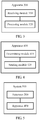
- FIG. 4 shows a data transmission apparatus 400 according to an embodiment of this application.
- the apparatus 400 may be the first terminal device 110 or the second terminal device 120 in the method 200, and the apparatus 400 includes:
- the apparatus 400 further includes a first receiving module, configured to: before the first multiple access signature MAS for sending the first data is determined, receive second indication information sent by the network device 130, where the second indication information is used to indicate a first MAS set; and the determining module 420 is specifically configured to: determine the first MAS set according to the second indication information; and determine the first MAS in the first MAS set.
- a first receiving module configured to: before the first multiple access signature MAS for sending the first data is determined, receive second indication information sent by the network device 130, where the second indication information is used to indicate a first MAS set
- the determining module 420 is specifically configured to: determine the first MAS set according to the second indication information; and determine the first MAS in the first MAS set.
- the first receiving module is further configured to receive first indication information sent by the network device 130, where the first indication information is used by the apparatus to send the data by using the first MAS in the first MAS set; and the determining module 420 is further specifically configured to determine the first MAS in the first MAS set according to the first indication information.
- the determining module 420 is further specifically configured to determine the first MAS based on identification information of the apparatus 400 and a MAS sequence number in the first MAS set.
- the determining module 420 is further configured to determine the multiplexing resource before the first data is sent to the network device 130 on the multiplexing resource between the apparatus and the second terminal device 120 based on the first MAS.
- the apparatus 400 further includes a second receiving module, configured to receive fifth indication information sent by the network device 130; and the determining module 420 is further specifically configured to determine the multiplexing resource according to the fifth indication information.
- the fifth indication information is used to indicate, to the apparatus, that a first physical resource is the multiplexing resource; and the determining module 420 is further specifically configured to determine, according to the fifth indication information, that the first physical resource is the multiplexing resource.
- the apparatus 400 can send the data on all physical resources, and/or the second terminal device 120 can send data on all physical resources.
- the fifth indication information is further used to indicate, to the apparatus 400, that a physical resource of the second terminal device 120 is a first physical resource, and indicates that the apparatus 400 can send the data by using the physical resource of the second terminal device 120, and the first physical resource is the multiplexing resource.
- the apparatus 400 is an enhanced mobile broadband eMBB terminal device, and the second terminal device 120 is an ultra-reliable and low latency communications URLLC terminal device.
- the apparatus 400 is a URLLC terminal device, and the second terminal device 120 is an eMBB terminal device.
- FIG. 5 shows a data transmission system 500 according to an embodiment of this application.
- the system 500 includes the apparatus 300 and the apparatus 400.
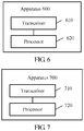
- FIG. 6 is a schematic block diagram of a data transmission apparatus 600 according to an embodiment of this application.
- the apparatus may be the network device 130 in the method 100.
- the apparatus 600 includes a transceiver 610 and a processor 620.
- the transceiver 610 is configured to receive first data sent by a first terminal device 110 on a multiplexing resource, where the first data is generated based on a first multiple access signature MAS.
- the transceiver 610 is further configured to receive second data sent by a second terminal device 120 on the multiplexing resource, where the second data is generated based on a second MAS, and the first MAS and the second MAS include different demodulation reference signals DMRSs and/or different preamble sequences.
- the processor 620 is configured to detect, based on the first MAS and the second MAS, the first data and the second data that are sent on the multiplexing resource.
- the apparatus 600 may correspond to the network device 130 in the method 200, and may implement corresponding functions of the network device 130 in the method 200. For brevity, details are not described herein again.
- FIG. 7 is a schematic block diagram of a data transmission apparatus 700 according to an embodiment of this application.
- the apparatus may be the first terminal device 110 or the second terminal device 120 in the method 200.
- the apparatus 700 includes a transceiver 710 and a processor 720.
- the processor 720 is configured to determine a multiple access signature MAS for sending first data.
- the transceiver 710 is configured to send the first data to a network device 130 on a multiplexing resource between the apparatus and a second terminal device 120 based on the first MAS, where a second MAS of the second terminal device 120 and the first MAS include different demodulation reference signals DMRSs and/or different preamble sequences.
- the apparatus 700 may correspond to the first terminal device 110 or the second terminal device 120 in the method 200, and may implement corresponding functions of the first terminal device 110 and the second terminal device 120 in the method 200. For brevity, details are not described herein again.
- the processor 620 and the processor 720 may be a central processing unit (central processing unit, CPU), or the processor may be another general purpose processor, a digital signal processor (DSP), an application-specific integrated circuit (ASIC), a field programmable gate array (FPGA) or another programmable logic device, a discrete gate or transistor logic device, a discrete hardware component, or the like.
- the general purpose processor may be a microprocessor, or the processor may be any conventional processor or the like.
- sequence numbers of the foregoing processes do not mean execution sequences in various embodiments of this application.
- the execution sequences of the processes should be determined according to functions and internal logic of the processes, and should not be construed as any limitation on the implementation processes of the embodiments of this application.
- the disclosed system, apparatus, and method may be implemented in other manners.
- the described apparatus embodiment is merely an example.
- the unit division is merely logical function division and may be other division in actual implementation.
- a plurality of units or components may be combined or integrated into another system, or some features may be ignored or not performed.
- the displayed or discussed mutual couplings or direct couplings or communication connections may be implemented through some interfaces, indirect couplings or communication connections between the apparatuses or units, or electrical connections, mechanical connections, or connections in other forms.
- the units described as separate parts may or may not be physically separate, and parts displayed as units may or may not be physical units, may be located in one position, or may be distributed on a plurality of network units. Some or all of the units may be selected according to actual requirements to achieve the objectives of the solutions of the embodiments in this application.
- functional units in the embodiments of this application may be integrated into one processing unit, or each of the units may exist alone physically, or two or more units are integrated into one unit.
- the integrated unit may be implemented in a form of hardware, or may be implemented in a form of a software functional unit.
- the integrated unit When the integrated unit is implemented in the form of a software functional unit and sold or used as an independent product, the integrated unit may be stored in a computer-readable storage medium. Based on such an understanding, the technical solutions of the embodiments of this application essentially, or the part contributing to the prior art, or all or some of the technical solutions may be implemented in the form of a software product.
- the computer software product is stored in a storage medium and includes several indications for instructing a computer device (which may be a personal computer, a server, or a network device) to perform all or some of the steps of the methods described in the embodiments of this application.
- the foregoing storage medium includes: any medium that can store program code, such as a USB flash drive, a removable hard disk, a read-only memory (Read-Only Memory, ROM), a random access memory (Random Access Memory, RAM), a magnetic disk, or an optical disc.
- program code such as a USB flash drive, a removable hard disk, a read-only memory (Read-Only Memory, ROM), a random access memory (Random Access Memory, RAM), a magnetic disk, or an optical disc.
Landscapes
- Engineering & Computer Science (AREA)
- Signal Processing (AREA)
- Computer Networks & Wireless Communication (AREA)
- Mobile Radio Communication Systems (AREA)
Description
- This application claims priority to Chinese Patent Application No.
201710008129.0 - Embodiments of this application relate to the communications field, and in particular, to a data transmission method and apparatus in the communications field.
- Enhanced mobile broadband (enhanced mobile broadband, eMBB) and ultra-reliable and low latency communications (ultra-reliable low latency communication, URLLC) are two important scenarios in a future network system. Compared with an existing mobile broadband service scenario, the eMBB further improves performance such as a system capacity, and enhances user experience. The eMBB corresponds to a high-traffic mobile broadband service such as a 3D/ultra-high definition video. For services such as Internet of Vehicles, unmanned driving, and industrial control, the system capacity is no longer a major issue, but a quite high requirement is imposed on latency and reliability. The URLLC can meet such the requirement for a low-latency and high-reliability communications service. Because of limited available resources, if an eMBB terminal device and a URLLC terminal device simultaneously send data on a same physical resource, it is difficult for a network device to detect the data sent by the two terminal devices. Consequently, data transmission performance is relatively poor. The document SPREADTRUM COMMUNICATIONS: "Considerations on pre-configured resource for grant-free based UL non-orthogonal MA",3GPP DRAFT; Rl-1608919, RAN WG1, Lisbon, Portugal, October 2016, proposes to group UEs into several groups and multiple UEs can transmit on the same physical resource by employing different MA signatures. The Document LG ELECTRONICS: "Discussion on feedback signaling for grant-free MA", 3GPP DRAFT; R1-1609226, RAN WG1, Lisbon, Portugal, October 2016, discusses mapping rules of DMRS and MAS.
- Embodiments of this application provide a data transmission method and apparatus according to the independent claims, so as to improve data transmission performance.
- Aspects of the present invention are provided in the independent claims. Preferred embodiments are provided in the dependent claims.
- The scope of the present invention is determined only by the scope of the appended claims. Any embodiment/aspect (of the invention/disclosure) referred to in this description and not fully falling within the scope of said appended claims is an example useful for understanding the present invention.
-
-
FIG. 1 is a schematic diagram of an application scenario according to an embodiment of this application; -
FIG. 2 is a schematic diagram of a data transmission method according to an embodiment of this application; -
FIG. 3 is a schematic block diagram of a data transmission apparatus according to an embodiment of this application; -
FIG. 4 is a schematic block diagram of another data transmission apparatus according to an embodiment of this application; -
FIG. 5 is a schematic block diagram of a data transmission system according to an embodiment of this application; -
FIG. 6 is a schematic block diagram of a data transmission apparatus according to an embodiment of this application; and -
FIG. 7 is a schematic block diagram of another data transmission apparatus according to an embodiment of this application. - It should be understood that the technical solutions of the embodiments of this application may be applied to various communications systems, such as a Global System for Mobile Communications (Global System for Mobile Communications, GSM) system, a Code Division Multiple Access (Code Division Multiple Access, CDMA) system, a Wideband Code Division Multiple Access (Wideband Code Division Multiple Access, WCDMA) system, a general packet radio service (general packet radio service, GPRS), a Long Term Evolution (Long Term Evolution, LTE) system, an LTE frequency division duplex (frequency division duplex, FDD) system, LTE time division duplex (time division duplex, TDD), Universal Mobile Telecommunications System (Universal Mobile Telecommunications System, UMTS), a Worldwide Interoperability for Microwave Access (Worldwide Interoperability for Microwave Access, WiMAX) communications system, a wireless local area network (wireless local area network, WLAN), or a future fifth generation (the fifth generation, 5G) wireless communications system.
-
FIG. 1 is a schematic diagram of an application scenario according to an embodiment of this application, including: - a
first terminal device 110, configured to: generate first data based on a first MAS, and send the first data to anetwork device 130 on a multiplexing resource (a box inFIG. 1 ); - a
second terminal device 120, configured to: generate second data based on a second MAS, and send the second data to thenetwork device 130 on the multiplexing resource; and - the
network device 130, configured to receive, on the multiplexing resource, the first data sent by thefirst terminal device 110 and the second data sent by thesecond terminal device 120. - In the prior art, when the
first terminal device 110 and thesecond terminal device 120 send the first data and the second data to thenetwork device 130 on the multiplexing resource, the first data and the second data interfere with each other, and thenetwork device 130 cannot well detect the first data and the second data. Consequently, data transmission performance is relatively poor. In this embodiment of this application, the first MAS for generating the first data and the second MAS for generating the second data may include different DMRSs and/or different preamble sequences. In this way, when receiving the first data and the second data on the multiplexing resource, thenetwork device 130 may jointly detect the first data and the second data by using the first MAS and the second MAS, so as to improve data transmission performance. - In this embodiment of this application, the first
terminal device 110 may be a URLLC terminal device, and thesecond terminal device 120 may be an eMBB terminal device. Alternatively, thefirst terminal device 110 may be an eMBB terminal device, and thesecond terminal device 120 may be a URLLC terminal device. Alternatively, thefirst terminal device 110 may be an eMBB terminal device, and thesecond terminal device 120 may be an eMBB terminal device. Alternatively, the firstterminal device 110 may be a URLLC terminal device, and thesecond terminal device 120 may be a URLLC terminal device. Devices what the firstterminal device 110 and the secondterminal device 120 are specifically are not limited in this embodiment of this application. - It should be understood that in this embodiment of this application, the first
terminal device 110 and the secondterminal device 120 may be referred to as user equipment (user equipment, UE), a terminal device, a mobile station (mobile station, MS), a mobile terminal (Mobile Terminal), a terminal device in a future 5G network, or the like. The terminal device may communicate with one or more core networks over a radio access network (radio access network, RAN). For example, the terminal may be a mobile phone (also referred to as a "cellular" phone) or a computer having a mobile terminal. For example, the terminal may be a portable, pocket-sized, handheld, computer built-in, or in-vehicle mobile apparatus, which exchanges voice and/or data with the radio access network. - It should be further understood that the
network device 130 may be configured to communicate with a mobile device. Thenetwork device 130 may be a base transceiver station (base transceiver station, BTS) in GSM or CDMA, or may be a NodeB (NodeB, NB) in WCDMA, or may be an evolved NodeB (evolved node B, eNB or eNodeB) in LTE, or may be a relay station or an access point, or may be an in-vehicle device, a wearable device, or an access network device in a future 5G network. -
FIG. 2 shows adata transmission method 200 according to an embodiment of this application. Themethod 200 includes the following steps. - S210. A first
terminal device 110 determines a first MAS for sending first data. - In an optional embodiment, before S210, the
method 200 includes: sending, by thenetwork device 130, second indication information to the firstterminal device 110; and receiving, by the firstterminal device 110, the second indication information sent by thenetwork device 130, where the second indication information is used to indicate a first MAS set; and S210 includes: determining, by the firstterminal device 110, the first MAS set according to the second indication information; and determining, by the firstterminal device 110, the first MAS in the first MAS set. Optionally, the first MAS set may not be indicated by using the second indication information sent by thenetwork device 130, and may be a first MAS set specified in the protocol. - The first
terminal device 110 determines the first MAS in the first MAS set in two manners. - In a first manner, when the first
terminal device 110 works in an authorization mode, thenetwork device 130 sends first indication information to the firstterminal device 110. The first indication information is used to instruct the firstterminal device 110 to send the data by using the first MAS in the first MAS set. The firstterminal device 110 receives the first indication information sent by thenetwork device 130, and the determining, by the firstterminal device 110, the first MAS in the first MAS set includes: determining, by the firstterminal device 110, the first MAS in the first MAS set according to the first indication information. Optionally, the first indication information may instruct the firstterminal device 110 to send all data or only the first data by using the first MAS in the first MAS set. - In a second manner, when the first
terminal device 110 works in an authorization-free mode, the firstterminal device 110 determines the first MAS based on identification information of thefirst terminal device 110 and a MAS sequence number in the first MAS set. For example, the MAS sequence number in the MAS set may be 0, 1, ..., and K-1. Assuming that the identification information of the firstterminal device 110 is N, the firstterminal device 110 may select a (mod(N, K))th MAS for access, where mod is a modulo operation. Certainly, the MAS sequence number in the MAS set may also be a frame number, a slot number, a cell ID, or the like. - In an optional embodiment, after the first
terminal device 110 determines the first MAS in the first MAS set, the firstterminal device 110 sends a first DMRS and/or a preamble sequence in the first MAS set to thenetwork device 130. Thenetwork device 130 receives the first DMRS and/or the first preamble sequence that are/is sent by the firstterminal device 110. - In an optional embodiment, before S250, the
method 200 further includes: determining, by thenetwork device 130, the first MAS of the firstterminal device 110. The determining, by thenetwork device 130, the first MAS of the firstterminal device 110 includes: determining, by thenetwork device 130, the first MAS based on the first DMRS and/or the first preamble sequence and a first mapping relationship. The first mapping relationship is used to indicate a correspondence between a MAS and a DMRS and/or a preamble sequence that are/is sent by the firstterminal device 110. - Specifically, the first
terminal device 110 may work in an authorization-free mode, thenetwork device 130 stores the first mapping relationship, and the first mapping relationship indicates the correspondence between a MAS and a DMRS and/or a preamble sequence. When selecting the first MAS, the firstterminal device 110 sends the first DMRS and/or the first preamble sequence in the first MAS to thenetwork device 130. When receiving the first DMRS and/or the first preamble sequence, thenetwork device 130 finds, based on the stored first mapping relationship, the first MAS corresponding to the first DMRS and/or the first preamble sequence. It may be understood that the first mapping relationship is used to indicate a mapping relationship between the first DMRS and the first MAS, or the first mapping relationship is used to indicate a mapping relationship between the first preamble sequence and the first MAS, or the first mapping relationship is used to indicate a mapping relationship between the first preamble sequence as well as the first DMRS and the first MAS. Optionally, the protocol may specify that the firstterminal device 110 uses the first DRMS and/or the first preamble sequence. In this way, when receiving the first DMRS and/or the first preamble sequence, thenetwork device 130 may determine that the first DMRS and/or the first preamble sequence are/is sent by the firstterminal device 110, and then find the corresponding first MAS based on the first mapping relationship. - In an optional embodiment, before S220, the
method 200 further includes: determining, by thenetwork device 130, the multiplexing resource; and sending, by thenetwork device 130, fifth indication information to the firstterminal device 110, where the fifth indication information is used by the firstterminal device 110 to determine the multiplexing resource. Optionally, before S220, themethod 200 includes: determining, by the firstterminal device 110, the multiplexing resource; and the determining, by the firstterminal device 110, the multiplexing resource includes: receiving, by the firstterminal device 110, fifth indication information sent by thenetwork device 130; and determining the multiplexing resource according to the fifth indication information. - In an optional embodiment, the fifth indication information is used to indicate, to the first
terminal device 110, that a first physical resource is the multiplexing resource. - In an optional embodiment, the first
terminal device 110 can send the data on all physical resources. - Specifically, the fifth indication information may directly indicate, to the first
terminal device 110, that the first physical resource is the multiplexing resource. When the firstterminal device 110 is an eMBB terminal device, the eMBB terminal device may occupy all the physical resources by default. When receiving the fifth indication information sent by thenetwork device 130, the eMBB terminal device may determine that the first physical resource is the multiplexing resource, and the remaining physical resources other than the first physical resource are dedicated resources of the eMBB terminal device. In this way, the eMBB terminal device may use different coding manners for data sent on the multiplexing resource and data sent on the dedicated resources. For example, the eMBB terminal device may send the data on the multiplexing resource by using one MAS, and send the data on the dedicated resources by using another MAS. A MAS used to send the data on the multiplexing resource is different from a MAS used to send the data on the dedicated resources. Further, thenetwork device 130 may indicate, to the firstterminal device 110, a MAS used by the secondterminal device 120 to send the data on the multiplexing resource. In this way, when selecting a MAS, the terminal device may avoid the MAS of the secondterminal device 120, and select a MAS different from that of the secondterminal device 120 to send the data. - In an optional embodiment, the fifth indication information is further used to indicate, to the first
terminal device 110, that a physical resource of the secondterminal device 120 is a first physical resource, and indicates that the firstterminal device 110 can send the data by using the physical resource of the secondterminal device 120, and the first physical resource is the multiplexing resource. - Specifically, by default, the first
terminal device 110 and the secondterminal device 120 may send data by using different resources. The fifth indication information may further indicate, to the firstterminal device 110, that the physical resource of the secondterminal device 120 is the first physical resource, and the fifth indication information may further indicate that the firstterminal device 110 can send the data by using the physical resource of the secondterminal device 120, or the fifth indication information may further indicate that the firstterminal device 110 cannot send the data by using the physical resource of the secondterminal device 120. In this way, the firstterminal device 110 may determine, according to the fifth indication information, whether to use the physical resource of the secondterminal device 120 as the multiplexing resource. - S220. The first
terminal device 110 sends the first data to anetwork device 130 on a multiplexing resource between the firstterminal device 110 and a secondterminal device 120 based on the first MAS, and thenetwork device 130 receives the first data sent by the firstterminal device 110 on the multiplexing resource, where the first data is generated based on the first multiple access signature MAS. - Specifically, that the first data is generated based on the first MAS may be as follows: A MAS in the first MAS set may include different sparse code multiple access (sparse code multiple access, SCMA) codebooks. When the first MAS includes a specific SCMA codebook, the first
terminal device 110 maps bit data to a multi-dimensional modulation symbol based on the SCMA codebook, in other words, the multi-dimensional modulation symbol is the first data. A MAS in the first MAS set may include different pattern division multiple access (pattern division multiple access, PDMA) spread spectrum patterns. When the first MAS includes a specific PDMA, the firstterminal device 110 first maps bit data to a quadrature amplitude modulation (quadrature amplitude modulation, QAM) symbol, and then performs spectrum spreading based on the specific PDMA spread spectrum pattern, to generate the first data. A MAS in the first MAS set may include different multi-user shared access (multiple user share access, MUSA) spread spectrum sequences. When the first MAS includes a specific MUSA spread spectrum sequence, the firstterminal device 110 maps bit data to a QAM symbol, and then performs spectrum spreading based on the specific MUSA spread spectrum sequence, to generate the first data. A MAS in the first MAS set may include different interleaver division multiple access (interleaver division multiple access, IDMA) interleaver patterns. When the first MAS includes a specific IDMA, the firstterminal device 110 first maps bit data to a QAM symbol, and then performs interleaving based on the specific IDMA interleaver pattern, to generate the first data. A MAS in the first MAS set may include unavailable interleave-grid multiple access (interleave-grid multiple access, IGMA) interleaver patterns. When the first MAS includes a specific IGMA, the firstterminal device 110 first maps bit data to a QAM symbol, and then performs interleaving based on the specific IGMA interleaver pattern, to generate the first data. - S230. The second
terminal device 120 determines a second MAS for sending second data, where the first MAS and the second MAS include different demodulation reference signals DMRSs and/or different preamble sequences. - In an optional embodiment, before S230, the
method 200 includes: sending, by thenetwork device 130, fourth indication information to the secondterminal device 120, where the fourth indication information is used to indicate the second MAS set; and S230 includes: determining, by the secondterminal device 120, the second MAS set according to the fourth indication information; and determining, by the secondterminal device 120, the second MAS in the second MAS set. Optionally, the second MAS set may not be indicated by using the fourth indication information sent by thenetwork device 130, and may be a second MAS set specified in the protocol. - The second
terminal device 120 determines the second MAS in the second MAS set in two manners. - In a first manner, the
network device 130 sends third indication information to the secondterminal device 120, and the third indication information is used to instruct the secondterminal device 120 to send the data by using the second MAS in the second MAS set. The secondterminal device 120 receives the third indication information sent by thenetwork device 130, and the determining, by the secondterminal device 120, the second MAS in the second MAS set includes: determining, by the secondterminal device 120, the second MAS in the second set according to the second indication information. - In a second manner, the second
terminal device 120 determines the second MAS based on identification information of the secondterminal device 120 and a MAS sequence number in the second MAS set. - In an optional embodiment, before S250, the
method 200 further includes: determining, by thenetwork device 130, the second MAS of the secondterminal device 120. The determining, by thenetwork device 130, the second MAS of the secondterminal device 120 includes: determining, by thenetwork device 130, the second MAS based on the second DMRS and/or the second preamble sequence and a second mapping relationship. The second mapping relationship is used to indicate a correspondence between a MAS and a DMRS and/or a preamble sequence that are/is sent by the secondterminal device 120. - Specifically, the second
terminal device 120 may work in an authorization-free mode, thenetwork device 130 stores the second mapping relationship, and the second mapping relationship indicates the correspondence between a MAS and a DMRS and/or a preamble sequence. When selecting the second MAS, the secondterminal device 120 sends the second DMRS and/or the second preamble sequence in the second MAS to thenetwork device 130. When receiving the second DMRS and/or the second preamble sequence, thenetwork device 130 finds, based on the stored second mapping relationship, the second MAS corresponding to the second DMRS and/or the second preamble sequence. It may be understood that the second mapping relationship is used to indicate a mapping relationship between the second DMRS and the second MAS, or the second mapping relationship is used to indicate a mapping relationship between the second preamble sequence and the second MAS, or the second mapping relationship is used to indicate a mapping relationship between the second preamble sequence as well as the second DMRS and the second MAS. Optionally, the protocol may specify that the secondterminal device 120 uses the second DRMS and/or the second preamble sequence. In this way, when receiving the second DMRS and/or the second preamble sequence, thenetwork device 130 may determine that the second DMRS and/or the second preamble sequence are/is sent by the secondterminal device 120, and then find the corresponding second MAS based on the second mapping relationship. - In an optional embodiment, before S240, the
method 200 further includes: determining, by thenetwork device 130, the multiplexing resource; and sending, by thenetwork device 130, sixth indication information to the secondterminal device 120, where the sixth indication information is used to instruct the secondterminal device 120 to determine the multiplexing resource. Optionally, before S240, themethod 200 includes: determining, by the secondterminal device 120, the multiplexing resource; and the determining, by the secondterminal device 120, the multiplexing resource includes: receiving, by the secondterminal device 120, sixth indication information sent by thenetwork device 130; and determining the multiplexing resource according to the sixth indication information. - In an optional embodiment, the sixth indication information is used to indicate, to the second
terminal device 120, that the first physical resource is the multiplexing resource. - In an optional embodiment, the second
terminal device 120 can send the data on all physical resources. - Specifically, the sixth indication information may directly indicate, to the second
terminal device 120, that the first physical resource is the multiplexing resource. The secondterminal device 120 may be a URLLC terminal device, and the URLLC terminal device may occupy all the physical resources by default. When receiving the fifth indication information sent by thenetwork device 130, the URLLC terminal device may determine that the first physical resource is the multiplexing resource, and the remaining physical resources other than the first physical resource are dedicated resources of the URLLC terminal device. In this way, the URLLC terminal device may use different coding manners for data sent on the multiplexing resource and data sent on the dedicated resources. - In an optional embodiment, the sixth indication information is used to indicate, to the second
terminal device 120, that a physical resource of the firstterminal device 110 is a first physical resource, and indicates that the secondterminal device 120 can send the data by using the physical resource of the firstterminal device 110, and the first physical resource is the multiplexing resource. - Specifically, by default, the first
terminal device 110 and the secondterminal device 120 may send data by using different resources. The sixth indication information may further indicate, to the secondterminal device 120, that the physical resource of the firstterminal device 110 is the first physical resource, and the sixth indication information may further indicate that the secondterminal device 120 can send the data by using the physical resource of the firstterminal device 110, or the sixth indication information may further indicate that the secondterminal device 120 cannot send the data by using the physical resource of the firstterminal device 110. In this way, the secondterminal device 120 may determine, according to the sixth indication information, whether to use the physical resource of the firstterminal device 110 as the multiplexing resource. - S240. The second
terminal device 120 sends the second data to thenetwork device 130 on the multiplexing resource based on the second MAS, and thenetwork device 130 receives the second data sent by the secondterminal device 120 on the multiplexing resource, where the second data is generated based on the second MAS. - Specifically, that the second data is generated based on the second MAS may be as follows: A MAS in the second MAS set may include different SCMA codebooks. When the second MAS includes a specific SCMA codebook, the second
terminal device 120 maps bit data to a multi-dimensional modulation symbol based on the SCMA codebook, in other words, the multi-dimensional modulation symbol is the second data. A MAS in the second MAS set may include different PDMA spread spectrum patterns. When the second MAS includes a specific PDMA, the secondterminal device 120 first maps bit data to a QAM symbol, and then performs spectrum spreading based on the specific PDMA spread spectrum pattern, to generate the second data. A MAS in the second MAS set may include different MUSA spread spectrum sequences. When the second MAS includes a specific MUSA spread spectrum sequence, the secondterminal device 120 maps bit data to a QAM symbol, and then performs spectrum spreading based on the specific MUSA spread spectrum sequence, to generate the second data. A MAS in the second MAS set may include different IDMA interleaver patterns. When the second MAS includes a specific IDMA, the secondterminal device 120 first maps bit data to a QAM symbol, and then performs interleaving based on the specific IDMA interleaver pattern, to generate the second data. A MAS in the second MAS set may include unavailable IGMA interleaver patterns. When the second MAS includes a specific IGMA, the secondterminal device 120 first maps bit data to a QAM symbol, and then performs interleaving based on the specific IGMA interleaver pattern, to generate the second data. - S250. The
network device 130 detects, based on the first MAS and the second MAS, the first data and the second data that are sent on the multiplexing resource. - In an optional embodiment, S250 includes: detecting, by the
network device 130 based on the first MAS and the second MAS by using a message passing algorithm MPA, the first data and the second data that are sent on the multiplexing resource. Thenetwork device 130 may detect, based on the first MAS and the second MAS by using the MPA, the first data and the second data that are sent on the multiplexing resource, or may certainly detect, by using another algorithm, the first data and the second data that are sent on the multiplexing resource. This is not limited in this embodiment of this application. - For example, when the first
terminal device 110 is an eMBB terminal device, and the secondterminal device 120 is a URLLC terminal device, thenetwork device 130 receives a symbol y(t) on a tth resource element (resource element, RE), which may be expressed by using the following formula (1):
C 1 and C 2 are respectively codebook numbers of the eMBB terminal device and the URLLC terminal device, hi (t) represents a channel gain of the eMBB terminal device, hj (t) represents a channel gain of the URLLC terminal device, xi (t) represents a symbol sent by an ith codebook of the eMBB terminal device on the tth RE, x j (t) represents a symbol sent by a jth codebook of the URLLC terminal device on the tth RE, and n(t) represents noise. Based on the received symbol y(t), thenetwork device 130 determines hi (t) based on the DMRS and/or the preamble sequence that are/is included in the first MAS, determines hj (t) based on the DMRS and/or the preamble sequence that are/is included in the second MAS, and obtains xi (t) and xj (t) based on the MPA or by using another method. - In an optional embodiment, the first
terminal device 110 is an enhanced mobile broadband eMBB terminal device, and the secondterminal device 120 is an ultra-reliable and low latency communications URLLC terminal device. In this way, the eMBB terminal device needs to occupy a relatively large quantity of resources while increasing a system capacity, for example, may occupy all the physical resources. When the URLLC terminal device sends data on some physical resources, a DMRS in the MAS used by the eMBB terminal device is different from a DMRS in the MAS used by the URLLC terminal device, and/or a preamble sequence in the MAS used by the eMBB terminal device is different from a preamble sequence in the MAS used by the URLLC terminal device. In this way, thenetwork device 130 may detect the first data and the second data that are received on the multiplexing resource. Therefore, data transmission performance can be improved while a key performance indicator of the URLLC terminal device is met. - It should be understood that a sequence of performing S210, S220, S230, and S240 in the
method 200 may not be related to a sequence number. For example, S210 and S220 may be simultaneously performed, and S220 and S240 may be simultaneously performed. In other words, the firstterminal device 110 and the secondterminal device 120 may simultaneously send the first data and the second data on the multiplexing resource, and thenetwork device 130 may receive the first data and the second data on the multiplexing resource. - It should be understood that the first MAS set and the second MAS set mentioned in this embodiment of this application each include a plurality of MASs, and each MAS includes a DMRS and/or a preamble sequence and at least one of the following five items: a codebook (or a codeword), a sequence (Sequence), an interleaver pattern (Interleaver pattern), a mapping pattern (mapping pattern), a spatial dimension (Spatial-dimension), and a power dimension (Power-dimension). Each MAS includes different DMRSs and/or different preamble sequences, and elements included in each MAS except the DMRSs and the preamble sequences may be the same or different. This is not limited in this embodiment of this application.
- It should be understood that in this embodiment of this application, the first
terminal device 110 may send the first data, or may send the first DMRS and/or the first preamble sequence. The secondterminal device 120 may send the second data, or may send the second DMRS and/or the second preamble sequence. Herein, the data sent by either of the terminal devices may be sent together with the DMRS. Alternatively, the data and the DMRS may be separately sent, and the DMRS is sent before the data. Alternatively, the DMRS and the preamble sequence are simultaneously sent before the data. A sending manner is not limited in this embodiment of this application. -
FIG. 3 shows a data transmission apparatus 300 according to an embodiment of this application. The apparatus 300 may be thenetwork device 130 in themethod 200, and the apparatus 300 includes: - a
receiving module 310, configured to receive first data sent by a firstterminal device 110 on a multiplexing resource, where the first data is generated based on a first multiple access signature MAS, where - the receiving
module 310 is further configured to receive second data sent by a secondterminal device 120 on the multiplexing resource, where the second data is generated based on a second MAS, and the first MAS and the second MAS include different demodulation reference signals DMRSs and/or different preamble sequences; and - a
processing module 320, configured to detect, based on the first MAS and the second MAS, the first data and the second data that are sent on the multiplexing resource. - In an optional embodiment, the
processing module 320 is further configured to determine the first MAS of the first terminal device before the first data sent by the firstterminal device 110 on the multiplexing resource is received. - In an optional embodiment, the receiving
module 310 is further configured to receive a first DMRS and/or a first preamble sequence that are/is sent by the firstterminal device 110; and theprocessing module 320 is specifically configured to determine the first MAS based on the first DMRS and/or the first preamble sequence and a first mapping relationship, where the first mapping relationship is used to indicate a correspondence between a MAS and a DMRS and/or a preamble sequence that are/is sent by the firstterminal device 110. - In an optional embodiment, the apparatus 300 further includes a first sending module, configured to send first indication information to the first
terminal device 110, where the first indication information is used to instruct the firstterminal device 110 to send the data by using the first MAS in a first MAS set. - In an optional embodiment, the first sending module is configured to send second indication information to the first
terminal device 110 before sending the first indication information to the firstterminal device 110, where the second indication information is used to indicate the first MAS set. - In an optional embodiment, the
processing module 320 is further configured to determine the second MAS of the secondterminal device 120 before the second data sent by the secondterminal device 120 on the multiplexing resource is received. - In an optional embodiment, the receiving
module 310 is further configured to receive a second DMRS and/or a second preamble sequence that are/is sent by the secondterminal device 120; and theprocessing module 320 is further specifically configured to determine the second MAS based on the second DMRS and/or the second preamble sequence and a second mapping relationship, where the second mapping relationship is used to indicate a correspondence between a MAS and a DMRS and/or a preamble sequence that are/is sent by the secondterminal device 120. - In an optional embodiment, the apparatus 300 further includes a second sending module, configured to send third indication information to the second
terminal device 120, where the third indication information is used to instruct the secondterminal device 120 to send the data by using the second MAS in a second MAS set. - In an optional embodiment, the second sending module is further configured to send fourth indication information to the second
terminal device 120 before sending the third indication information to the secondterminal device 120, where the fourth indication information is used to indicate the second MAS set. - In an optional embodiment, the
processing module 320 is further configured to determine the multiplexing resource before the first data sent by the firstterminal device 110 on the multiplexing resource is received; and the apparatus further includes a third sending module, configured to send fifth indication information to the firstterminal device 110, where the fifth indication information is used by the firstterminal device 110 to determine the multiplexing resource; and/or the third sending module is further configured to send sixth indication information to the secondterminal device 120, where the sixth indication information is used to instruct the secondterminal device 120 to determine the multiplexing resource. - In an optional embodiment, the fifth indication information is used to indicate, to the first
terminal device 110, that a first physical resource is the multiplexing resource, and the sixth indication information is used to indicate, to the secondterminal device 120, that the first physical resource is the multiplexing resource. - In an optional embodiment, the first
terminal device 110 can send the data on all physical resources, and/or the secondterminal device 120 can send the data on all physical resources. - In an optional embodiment, the fifth indication information is further used to indicate, to the first
terminal device 110, that a physical resource of the secondterminal device 120 is a first physical resource, and indicates that the firstterminal device 110 can send the data by using the physical resource of the secondterminal device 120, and the first physical resource is the multiplexing resource. - In an optional embodiment, the sixth indication information is used to indicate, to the second
terminal device 120, that a physical resource of the firstterminal device 110 is a first physical resource, and indicates that the secondterminal device 120 can send the data by using the physical resource of the firstterminal device 110, and the first physical resource is the multiplexing resource. - In an optional embodiment, the
processing module 320 is further specifically configured to detect, based on the first MAS and the second MAS by using a message passing algorithm MPA, the first data and the second data that are sent on the multiplexing resource. - In an optional embodiment, the first
terminal device 110 is an enhanced mobile broadband eMBB terminal device, and the secondterminal device 120 is an ultra-reliable and low latency communications URLLC terminal device. -
FIG. 4 shows a data transmission apparatus 400 according to an embodiment of this application. The apparatus 400 may be the firstterminal device 110 or the secondterminal device 120 in themethod 200, and the apparatus 400 includes: - a determining
module 410, configured to determine a first multiple access signature MAS for sending first data; and - a sending
module 420, configured to send the first data to anetwork device 130 on a multiplexing resource between the apparatus and a secondterminal device 120 based on the first MAS, where a second MAS of the secondterminal device 120 and the first MAS include different demodulation reference signals DMRSs and/or different preamble sequences. - In an optional embodiment, the apparatus 400 further includes a first receiving module, configured to: before the first multiple access signature MAS for sending the first data is determined, receive second indication information sent by the
network device 130, where the second indication information is used to indicate a first MAS set; and the determiningmodule 420 is specifically configured to: determine the first MAS set according to the second indication information; and determine the first MAS in the first MAS set. - In an optional embodiment, the first receiving module is further configured to receive first indication information sent by the
network device 130, where the first indication information is used by the apparatus to send the data by using the first MAS in the first MAS set; and the determiningmodule 420 is further specifically configured to determine the first MAS in the first MAS set according to the first indication information. - In an optional embodiment, the determining
module 420 is further specifically configured to determine the first MAS based on identification information of the apparatus 400 and a MAS sequence number in the first MAS set. - In an optional embodiment, the determining
module 420 is further configured to determine the multiplexing resource before the first data is sent to thenetwork device 130 on the multiplexing resource between the apparatus and the secondterminal device 120 based on the first MAS. - In an optional embodiment, the apparatus 400 further includes a second receiving module, configured to receive fifth indication information sent by the
network device 130; and the determiningmodule 420 is further specifically configured to determine the multiplexing resource according to the fifth indication information. - In an optional embodiment, the fifth indication information is used to indicate, to the apparatus, that a first physical resource is the multiplexing resource; and the determining
module 420 is further specifically configured to determine, according to the fifth indication information, that the first physical resource is the multiplexing resource. - In an optional embodiment, the apparatus 400 can send the data on all physical resources, and/or the second
terminal device 120 can send data on all physical resources. - In an optional embodiment, the fifth indication information is further used to indicate, to the apparatus 400, that a physical resource of the second
terminal device 120 is a first physical resource, and indicates that the apparatus 400 can send the data by using the physical resource of the secondterminal device 120, and the first physical resource is the multiplexing resource. - In an optional embodiment, the apparatus 400 is an enhanced mobile broadband eMBB terminal device, and the second
terminal device 120 is an ultra-reliable and low latency communications URLLC terminal device. - In an optional embodiment, the apparatus 400 is a URLLC terminal device, and the second
terminal device 120 is an eMBB terminal device. -
FIG. 5 shows adata transmission system 500 according to an embodiment of this application. Thesystem 500 includes the apparatus 300 and the apparatus 400. -
FIG. 6 is a schematic block diagram of a data transmission apparatus 600 according to an embodiment of this application. For example, the apparatus may be thenetwork device 130 in themethod 100. The apparatus 600 includes atransceiver 610 and aprocessor 620. - The
transceiver 610 is configured to receive first data sent by a firstterminal device 110 on a multiplexing resource, where the first data is generated based on a first multiple access signature MAS. Thetransceiver 610 is further configured to receive second data sent by a secondterminal device 120 on the multiplexing resource, where the second data is generated based on a second MAS, and the first MAS and the second MAS include different demodulation reference signals DMRSs and/or different preamble sequences. Theprocessor 620 is configured to detect, based on the first MAS and the second MAS, the first data and the second data that are sent on the multiplexing resource. - It should be understood that the apparatus 600 may correspond to the
network device 130 in themethod 200, and may implement corresponding functions of thenetwork device 130 in themethod 200. For brevity, details are not described herein again. -
FIG. 7 is a schematic block diagram of a data transmission apparatus 700 according to an embodiment of this application. The apparatus may be the firstterminal device 110 or the secondterminal device 120 in themethod 200. As shown inFIG. 7 , the apparatus 700 includes atransceiver 710 and aprocessor 720. - The
processor 720 is configured to determine a multiple access signature MAS for sending first data. Thetransceiver 710 is configured to send the first data to anetwork device 130 on a multiplexing resource between the apparatus and a secondterminal device 120 based on the first MAS, where a second MAS of the secondterminal device 120 and the first MAS include different demodulation reference signals DMRSs and/or different preamble sequences. - It should be understood that the apparatus 700 may correspond to the first
terminal device 110 or the secondterminal device 120 in themethod 200, and may implement corresponding functions of the firstterminal device 110 and the secondterminal device 120 in themethod 200. For brevity, details are not described herein again. - It should be understood that in the embodiments of this application, the
processor 620 and theprocessor 720 may be a central processing unit (central processing unit, CPU), or the processor may be another general purpose processor, a digital signal processor (DSP), an application-specific integrated circuit (ASIC), a field programmable gate array (FPGA) or another programmable logic device, a discrete gate or transistor logic device, a discrete hardware component, or the like. The general purpose processor may be a microprocessor, or the processor may be any conventional processor or the like. - It should be understood that the term "and/or" in this specification describes only an association relationship for describing associated objects and represents that three relationships may exist. For example, A and/or B may represent the following three cases: Only A exists, both A and B exist, and only B exists. In addition, the character "/" in this specification generally indicates an "or" relationship between the associated objects.
- It should be understood that sequence numbers of the foregoing processes do not mean execution sequences in various embodiments of this application. The execution sequences of the processes should be determined according to functions and internal logic of the processes, and should not be construed as any limitation on the implementation processes of the embodiments of this application.
- A person of ordinary skill in the art may be aware that, in combination with the examples described in the embodiments disclosed in this specification, method steps and units may be implemented by electronic hardware, computer software, or a combination thereof. To clearly describe the interchangeability between the hardware and the software, the foregoing has generally described steps and compositions of each embodiment according to functions. Whether the functions are performed by hardware or software depends on particular applications and design constraint conditions of the technical solutions. A person of ordinary skill in the art may use different methods to implement the described functions for each particular application, but it should not be considered that the implementation goes beyond the scope of this application.
- It may be clearly understood by a person skilled in the art that, for the purpose of convenient and brief description, for a detailed working process of the foregoing system, apparatus, and unit, refer to a corresponding process in the foregoing method embodiments. Details are not described herein again.
- In the several embodiments provided in this application, it should be understood that the disclosed system, apparatus, and method may be implemented in other manners. For example, the described apparatus embodiment is merely an example. For example, the unit division is merely logical function division and may be other division in actual implementation. For example, a plurality of units or components may be combined or integrated into another system, or some features may be ignored or not performed. In addition, the displayed or discussed mutual couplings or direct couplings or communication connections may be implemented through some interfaces, indirect couplings or communication connections between the apparatuses or units, or electrical connections, mechanical connections, or connections in other forms.
- The units described as separate parts may or may not be physically separate, and parts displayed as units may or may not be physical units, may be located in one position, or may be distributed on a plurality of network units. Some or all of the units may be selected according to actual requirements to achieve the objectives of the solutions of the embodiments in this application.
- In addition, functional units in the embodiments of this application may be integrated into one processing unit, or each of the units may exist alone physically, or two or more units are integrated into one unit. The integrated unit may be implemented in a form of hardware, or may be implemented in a form of a software functional unit.
- When the integrated unit is implemented in the form of a software functional unit and sold or used as an independent product, the integrated unit may be stored in a computer-readable storage medium. Based on such an understanding, the technical solutions of the embodiments of this application essentially, or the part contributing to the prior art, or all or some of the technical solutions may be implemented in the form of a software product. The computer software product is stored in a storage medium and includes several indications for instructing a computer device (which may be a personal computer, a server, or a network device) to perform all or some of the steps of the methods described in the embodiments of this application. The foregoing storage medium includes: any medium that can store program code, such as a USB flash drive, a removable hard disk, a read-only memory (Read-Only Memory, ROM), a random access memory (Random Access Memory, RAM), a magnetic disk, or an optical disc.
- The foregoing descriptions are merely specific embodiments of this application, but are not intended to limit the protection scope of this application. Any modification or replacement readily figured out by a person skilled in the art within the technical scope disclosed in this application shall fall within the protection scope of this application. Therefore, the protection scope of this application shall be subject to the protection scope of the claims.
Claims (8)
- A data transmission method, wherein the method comprises:receiving (S220), by a network device, first data sent by a first terminal device on a multiplexing resource, wherein the first data is generated based on a first multiple access signature , MAS;receiving (S240), by the network device, second data sent by a second terminal device on the multiplexing resource, wherein the second data is generated based on a second MAS, and the first MAS and the second MAS comprise different demodulation reference signals, DMRSs, and/or different preamble sequences; anddetecting (S250), by the network device based on the first MAS and the second MAS, the first data and the second data that are sent on the multiplexing resource, andthe method being characterized in that:
the method further comprises:sending, by the network device, first indication information to the first terminal device, wherein the first indication information is used to instruct the first terminal device to send the first data by using the first MAS in a first MAS set; andbefore the sending, by the network device, first indication information to the first terminal device, the method further comprises:
sending, by the network device, second indication information to the first terminal device, wherein the second indication information is used to indicate the first MAS set. - The method according to claim 1, wherein before the receiving, by the network device, the first data sent by the first terminal device on the multiplexing resource, the method further comprises:
determining, by the network device, the first MAS of the first terminal device. - The method according to claim 2, wherein the determining, by the network device, the first MAS of the first terminal device comprises:receiving, by the network device, a first DMRS and/or a first preamble sequence that are/is sent by the first terminal device; anddetermining, by the network device, the first MAS based on the first DMRS and/or the first preamble sequence and a first mapping relationship, wherein the first mapping relationship is used to indicate a correspondence between the first MAS and the first DMRS and/or the first preamble sequence that are/is sent by the first terminal device.
- A data transmission method, wherein the method comprises:determining (S210), by a first terminal device, a first multiple access signature, MAS, for sending first data; andsending (S220), by the first terminal device, the first data to a network device on a multiplexing resource between the first terminal device and a second terminal device based on the first MAS, wherein the second terminal device generates second data based on a second MAS and sends said second data on the multiplexing resource, and wherein the second MAS of the second terminal device and the first MAS comprise different demodulation reference signals DMRSs and/or different preamble sequences, andthe method being characterized in that:before the determining, by the first terminal device, the first multiple access signature MAS for sending the first data, the method further comprises:receiving, by the first terminal device, second indication information sent by the network device, wherein the second indication information is used to indicate a first MAS set; andthe determining, by the first terminal device, the firt MAS for sending the first data comprises:determining, by the first terminal device, the first MAS set according to the second indication information; anddetermining, by the first terminal device, the first MAS in the first MAS set, andwherein the determining, by the first terminal device, the first MAS in the first MAS set comprises:
receiving, by the first terminal device, first indication information sent by the network device, wherein the first indication information is used by the first terminal device to send the first data by using the first MAS in the first MAS set; andthe determining, by the first terminal device, the first MAS in the first MAS set comprises:determining, by the first terminal device, the first MAS in the first MAS set according to the first indication information; orthe determining, by the first terminal device, the first MAS in the first MAS set comprises:
determining, by the first terminal device, the first MAS based on identification information of the first terminal device and a MAS sequence number in the first MAS set. - A data transmission apparatus, wherein the apparatus comprises:a receiving module (310), configured to receive first data sent by a first terminal device on a multiplexing resource, wherein the first data is generated based on a first multiple access signature , MAS, whereinthe receiving module (310) is further configured to receive second data sent by a second terminal device on the multiplexing resource, wherein the second data is generated based on a second MAS, and the first MAS and the second MAS comprise different demodulation reference signals , DMRSs, and/or different preamble sequences; anda processing module (320), configured to detect, based on the first MAS and the second MAS, the first data and the second data that are sent on the multiplexing resource, andthe apparatus being characterized by that:
the apparatus further comprises:a first sending module, configured to send first indication information to the first terminal device, wherein the first indication information is used to instruct the first terminal device to send the first data by using the first MAS in a first MAS set, andwherein the first sending module is further configured to:
send second indication information to the first terminal device before sending the first indication information to the first terminal device, wherein the second indication information is used to indicate the first MAS set. - The apparatus according to claim 5, wherein the processing module (320) is further configured to:
determine the first MAS of the first terminal device before the first data sent by the first terminal device on the multiplexing resource is received. - The apparatus according to claim 6, wherein the receiving module is further configured to:receive a first DMRS and/or a first preamble sequence that are/is sent by the first terminal device; andthe processing module (320) is specifically configured to determine the first MAS based on the first DMRS and/or the first preamble sequence and a first mapping relationship, wherein the first mapping relationship is used to indicate a correspondence between the first MAS and the first DMRS and/or the first preamble sequence that are/is sent by the first terminal device.
- A data transmission apparatus, wherein the apparatus comprises:a determining module (410), configured to determine a first multiple access signature, MAS, for sending first data; anda sending module (420), configured to send the first data to a network device on a multiplexing resource between the apparatus and a second terminal device based on the first MAS, wherein the second terminal device is generating second data based on a second MAS and sending said second data on the multiplexing resource, and wherein the second MAS of the second terminal device and the first MAS comprise different demodulation reference signals, DMRS, and/or different preamble sequences, andthe apparatus being characterized by that:
the apparatus further comprises:a first receiving module, configured to: before the first multiple access signature MAS for sending the first data is determined, receive second indication information sent by the network device, wherein the second indication information is used to indicate a first MAS set; andthe determining module is specifically configured to:determine the first MAS set according to the second indication information; anddetermine the first MAS in the first MAS set, andwherein the first receiving module is further configured to:receive first indication information sent by the network device, wherein the first indication information is used by the apparatus to send the first data by using the first MAS in the first MAS set; andthe determining module is further specifically configured to determine the first MAS in the first MAS set according to the first indication information, orthe determining module is further specifically configured to determine the first MAS based on identification information of the apparatus and a MAS sequence number in the first MAS set.
Applications Claiming Priority (2)
| Application Number | Priority Date | Filing Date | Title |
|---|---|---|---|
| CN201710008129.0A CN108282282B (en) | 2017-01-05 | 2017-01-05 | Method and apparatus for transmitting data |
| PCT/CN2017/117448 WO2018126889A1 (en) | 2017-01-05 | 2017-12-20 | Data transmission method and apparatus |
Publications (3)
| Publication Number | Publication Date |
|---|---|
| EP3531771A1 EP3531771A1 (en) | 2019-08-28 |
| EP3531771A4 EP3531771A4 (en) | 2019-10-09 |
| EP3531771B1 true EP3531771B1 (en) | 2020-10-07 |
Family
ID=62789133
Family Applications (1)
| Application Number | Title | Priority Date | Filing Date |
|---|---|---|---|
| EP17890499.1A Active EP3531771B1 (en) | 2017-01-05 | 2017-12-20 | Wireless communication using multiple access techniques |
Country Status (5)
| Country | Link |
|---|---|
| US (1) | US20190306000A1 (en) |
| EP (1) | EP3531771B1 (en) |
| KR (1) | KR20190075128A (en) |
| CN (2) | CN111628853B (en) |
| WO (1) | WO2018126889A1 (en) |
Families Citing this family (1)
| Publication number | Priority date | Publication date | Assignee | Title |
|---|---|---|---|---|
| WO2019195241A1 (en) * | 2018-04-04 | 2019-10-10 | Idac Holdings, Inc. | Multiple access (ma) signature transmissions |
Family Cites Families (10)
| Publication number | Priority date | Publication date | Assignee | Title |
|---|---|---|---|---|
| FR2700087B1 (en) * | 1992-12-30 | 1995-02-10 | Alcatel Radiotelephone | Method for adaptive positioning of a speech coder / decoder within a communication infrastructure. |
| KR100747464B1 (en) * | 2002-01-05 | 2007-08-09 | 엘지전자 주식회사 | Deadlock avoidance method using timer for high speed downlink packet connection (HSDPA) system |
| US20110267948A1 (en) * | 2010-05-03 | 2011-11-03 | Koc Ali T | Techniques for communicating and managing congestion in a wireless network |
| CN102404854B (en) * | 2011-11-04 | 2018-04-06 | 中兴通讯股份有限公司 | The resource allocation method and system of a kind of uplink demodulation reference signal |
| US20140133395A1 (en) * | 2012-11-09 | 2014-05-15 | Samsung Electronics Co. Ltd | Methods and apparatus for identification of small cells |
| EP2919392B1 (en) * | 2014-03-11 | 2017-03-08 | Alcatel Lucent | Non-linear precoder with separate tracking |
| US20150263796A1 (en) * | 2014-03-14 | 2015-09-17 | Samsung Electronics Co., Ltd. | Channel state information for reporting an advanced wireless communications system |
| CN105763288B (en) * | 2014-12-16 | 2019-08-30 | 电信科学技术研究院 | Method and device for configuring and determining multi-user coding mode based on coding superposition |
| CN105792360B (en) * | 2014-12-24 | 2020-02-14 | 中兴通讯股份有限公司 | Method and device for resource allocation in super cell |
| CN106160831B (en) * | 2015-03-23 | 2019-09-17 | 电信科学技术研究院 | A kind of signal detecting method and device |
-
2017
- 2017-01-05 CN CN202010121430.4A patent/CN111628853B/en active Active
- 2017-01-05 CN CN201710008129.0A patent/CN108282282B/en active Active
- 2017-12-20 WO PCT/CN2017/117448 patent/WO2018126889A1/en not_active Ceased
- 2017-12-20 EP EP17890499.1A patent/EP3531771B1/en active Active
- 2017-12-20 KR KR1020197016229A patent/KR20190075128A/en not_active Abandoned
-
2019
- 2019-06-18 US US16/444,196 patent/US20190306000A1/en not_active Abandoned
Non-Patent Citations (1)
| Title |
|---|
| None * |
Also Published As
| Publication number | Publication date |
|---|---|
| US20190306000A1 (en) | 2019-10-03 |
| CN108282282B (en) | 2020-03-10 |
| WO2018126889A1 (en) | 2018-07-12 |
| CN111628853A (en) | 2020-09-04 |
| CN108282282A (en) | 2018-07-13 |
| EP3531771A1 (en) | 2019-08-28 |
| KR20190075128A (en) | 2019-06-28 |
| EP3531771A4 (en) | 2019-10-09 |
| CN111628853B (en) | 2021-12-10 |
Similar Documents
| Publication | Publication Date | Title |
|---|---|---|
| US20210274482A1 (en) | Method for Transmitting Downlink Control Information, Terminal Device and Network Device | |
| CN110419239B (en) | Wireless communication method and device | |
| CN104468019B (en) | The indicating means and equipment of signal resource | |
| US11265057B2 (en) | Method, terminal device and network device for transmitting physical uplink control channel (PUCCH) | |
| CN110149288B (en) | Method and device for determining time-domain density of phase tracking reference signal | |
| CA3043119A1 (en) | Uplink data transmission method, terminal device, and network device | |
| US11147030B2 (en) | Method for power control, and terminal device and network device | |
| EP3525504B1 (en) | Method for transmitting uplink signal and terminal device | |
| US11770834B2 (en) | Data transmission method, terminal device, and network device | |
| WO2021082900A1 (en) | Frequency-domain resource indication method and device | |
| TWI741025B (en) | Method and device for transmitting information | |
| EP3637889B1 (en) | Wireless communication method and apparatus | |
| WO2019033868A1 (en) | Precoding matrix set determination method and transmission device | |
| US11044037B2 (en) | Information transmission method and device | |
| US20190306000A1 (en) | Data Transmission Method and Apparatus | |
| US20170265219A1 (en) | Data transmission method and user equipment | |
| EP3595224A1 (en) | Information transmission method, terminal device and network device | |
| US10136430B2 (en) | Data transmission using frequency resources determined from frequency resource numbers | |
| EP3614611B1 (en) | Communication method and device | |
| US10284330B2 (en) | Data transmission method, device, and system | |
| CN108667582A (en) | Communication means, the network equipment and terminal device | |
| HK40002881B (en) | Method and apparatus for transmitting information |
Legal Events
| Date | Code | Title | Description |
|---|---|---|---|
| STAA | Information on the status of an ep patent application or granted ep patent |
Free format text: STATUS: THE INTERNATIONAL PUBLICATION HAS BEEN MADE |
|
| PUAI | Public reference made under article 153(3) epc to a published international application that has entered the european phase |
Free format text: ORIGINAL CODE: 0009012 |
|
| STAA | Information on the status of an ep patent application or granted ep patent |
Free format text: STATUS: REQUEST FOR EXAMINATION WAS MADE |
|
| 17P | Request for examination filed |
Effective date: 20190523 |
|
| AK | Designated contracting states |
Kind code of ref document: A1 Designated state(s): AL AT BE BG CH CY CZ DE DK EE ES FI FR GB GR HR HU IE IS IT LI LT LU LV MC MK MT NL NO PL PT RO RS SE SI SK SM TR |
|
| AX | Request for extension of the european patent |
Extension state: BA ME |
|
| REG | Reference to a national code |
Ref country code: DE Ref legal event code: R079 Ref document number: 602017025240 Country of ref document: DE Free format text: PREVIOUS MAIN CLASS: H04W0072040000 Ipc: H04L0005000000 |
|
| A4 | Supplementary search report drawn up and despatched |
Effective date: 20190906 |
|
| RIC1 | Information provided on ipc code assigned before grant |
Ipc: H04L 5/00 20060101AFI20190902BHEP Ipc: H04W 72/04 20090101ALI20190902BHEP |
|
| DAV | Request for validation of the european patent (deleted) | ||
| DAX | Request for extension of the european patent (deleted) | ||
| GRAP | Despatch of communication of intention to grant a patent |
Free format text: ORIGINAL CODE: EPIDOSNIGR1 |
|
| STAA | Information on the status of an ep patent application or granted ep patent |
Free format text: STATUS: GRANT OF PATENT IS INTENDED |
|
| INTG | Intention to grant announced |
Effective date: 20200415 |
|
| GRAS | Grant fee paid |
Free format text: ORIGINAL CODE: EPIDOSNIGR3 |
|
| GRAA | (expected) grant |
Free format text: ORIGINAL CODE: 0009210 |
|
| STAA | Information on the status of an ep patent application or granted ep patent |
Free format text: STATUS: THE PATENT HAS BEEN GRANTED |
|
| AK | Designated contracting states |
Kind code of ref document: B1 Designated state(s): AL AT BE BG CH CY CZ DE DK EE ES FI FR GB GR HR HU IE IS IT LI LT LU LV MC MK MT NL NO PL PT RO RS SE SI SK SM TR |
|
| REG | Reference to a national code |
Ref country code: GB Ref legal event code: FG4D |
|
| REG | Reference to a national code |
Ref country code: AT Ref legal event code: REF Ref document number: 1322312 Country of ref document: AT Kind code of ref document: T Effective date: 20201015 Ref country code: CH Ref legal event code: EP |
|
| REG | Reference to a national code |
Ref country code: IE Ref legal event code: FG4D |
|
| REG | Reference to a national code |
Ref country code: DE Ref legal event code: R096 Ref document number: 602017025240 Country of ref document: DE |
|
| REG | Reference to a national code |
Ref country code: NL Ref legal event code: MP Effective date: 20201007 |
|
| REG | Reference to a national code |
Ref country code: AT Ref legal event code: MK05 Ref document number: 1322312 Country of ref document: AT Kind code of ref document: T Effective date: 20201007 |
|
| PG25 | Lapsed in a contracting state [announced via postgrant information from national office to epo] |
Ref country code: FI Free format text: LAPSE BECAUSE OF FAILURE TO SUBMIT A TRANSLATION OF THE DESCRIPTION OR TO PAY THE FEE WITHIN THE PRESCRIBED TIME-LIMIT Effective date: 20201007 Ref country code: PT Free format text: LAPSE BECAUSE OF FAILURE TO SUBMIT A TRANSLATION OF THE DESCRIPTION OR TO PAY THE FEE WITHIN THE PRESCRIBED TIME-LIMIT Effective date: 20210208 Ref country code: RS Free format text: LAPSE BECAUSE OF FAILURE TO SUBMIT A TRANSLATION OF THE DESCRIPTION OR TO PAY THE FEE WITHIN THE PRESCRIBED TIME-LIMIT Effective date: 20201007 Ref country code: GR Free format text: LAPSE BECAUSE OF FAILURE TO SUBMIT A TRANSLATION OF THE DESCRIPTION OR TO PAY THE FEE WITHIN THE PRESCRIBED TIME-LIMIT Effective date: 20210108 Ref country code: NO Free format text: LAPSE BECAUSE OF FAILURE TO SUBMIT A TRANSLATION OF THE DESCRIPTION OR TO PAY THE FEE WITHIN THE PRESCRIBED TIME-LIMIT Effective date: 20210107 |
|
| REG | Reference to a national code |
Ref country code: LT Ref legal event code: MG4D |
|
| PG25 | Lapsed in a contracting state [announced via postgrant information from national office to epo] |
Ref country code: BG Free format text: LAPSE BECAUSE OF FAILURE TO SUBMIT A TRANSLATION OF THE DESCRIPTION OR TO PAY THE FEE WITHIN THE PRESCRIBED TIME-LIMIT Effective date: 20210107 Ref country code: SE Free format text: LAPSE BECAUSE OF FAILURE TO SUBMIT A TRANSLATION OF THE DESCRIPTION OR TO PAY THE FEE WITHIN THE PRESCRIBED TIME-LIMIT Effective date: 20201007 Ref country code: PL Free format text: LAPSE BECAUSE OF FAILURE TO SUBMIT A TRANSLATION OF THE DESCRIPTION OR TO PAY THE FEE WITHIN THE PRESCRIBED TIME-LIMIT Effective date: 20201007 Ref country code: LV Free format text: LAPSE BECAUSE OF FAILURE TO SUBMIT A TRANSLATION OF THE DESCRIPTION OR TO PAY THE FEE WITHIN THE PRESCRIBED TIME-LIMIT Effective date: 20201007 Ref country code: IS Free format text: LAPSE BECAUSE OF FAILURE TO SUBMIT A TRANSLATION OF THE DESCRIPTION OR TO PAY THE FEE WITHIN THE PRESCRIBED TIME-LIMIT Effective date: 20210207 Ref country code: ES Free format text: LAPSE BECAUSE OF FAILURE TO SUBMIT A TRANSLATION OF THE DESCRIPTION OR TO PAY THE FEE WITHIN THE PRESCRIBED TIME-LIMIT Effective date: 20201007 Ref country code: AT Free format text: LAPSE BECAUSE OF FAILURE TO SUBMIT A TRANSLATION OF THE DESCRIPTION OR TO PAY THE FEE WITHIN THE PRESCRIBED TIME-LIMIT Effective date: 20201007 |
|
| PG25 | Lapsed in a contracting state [announced via postgrant information from national office to epo] |
Ref country code: NL Free format text: LAPSE BECAUSE OF FAILURE TO SUBMIT A TRANSLATION OF THE DESCRIPTION OR TO PAY THE FEE WITHIN THE PRESCRIBED TIME-LIMIT Effective date: 20201007 Ref country code: HR Free format text: LAPSE BECAUSE OF FAILURE TO SUBMIT A TRANSLATION OF THE DESCRIPTION OR TO PAY THE FEE WITHIN THE PRESCRIBED TIME-LIMIT Effective date: 20201007 |
|
| REG | Reference to a national code |
Ref country code: DE Ref legal event code: R097 Ref document number: 602017025240 Country of ref document: DE |
|
| PG25 | Lapsed in a contracting state [announced via postgrant information from national office to epo] |
Ref country code: SM Free format text: LAPSE BECAUSE OF FAILURE TO SUBMIT A TRANSLATION OF THE DESCRIPTION OR TO PAY THE FEE WITHIN THE PRESCRIBED TIME-LIMIT Effective date: 20201007 Ref country code: LT Free format text: LAPSE BECAUSE OF FAILURE TO SUBMIT A TRANSLATION OF THE DESCRIPTION OR TO PAY THE FEE WITHIN THE PRESCRIBED TIME-LIMIT Effective date: 20201007 Ref country code: CZ Free format text: LAPSE BECAUSE OF FAILURE TO SUBMIT A TRANSLATION OF THE DESCRIPTION OR TO PAY THE FEE WITHIN THE PRESCRIBED TIME-LIMIT Effective date: 20201007 Ref country code: EE Free format text: LAPSE BECAUSE OF FAILURE TO SUBMIT A TRANSLATION OF THE DESCRIPTION OR TO PAY THE FEE WITHIN THE PRESCRIBED TIME-LIMIT Effective date: 20201007 Ref country code: SK Free format text: LAPSE BECAUSE OF FAILURE TO SUBMIT A TRANSLATION OF THE DESCRIPTION OR TO PAY THE FEE WITHIN THE PRESCRIBED TIME-LIMIT Effective date: 20201007 Ref country code: RO Free format text: LAPSE BECAUSE OF FAILURE TO SUBMIT A TRANSLATION OF THE DESCRIPTION OR TO PAY THE FEE WITHIN THE PRESCRIBED TIME-LIMIT Effective date: 20201007 |
|
| REG | Reference to a national code |
Ref country code: CH Ref legal event code: PL |
|
| PLBE | No opposition filed within time limit |
Free format text: ORIGINAL CODE: 0009261 |
|
| STAA | Information on the status of an ep patent application or granted ep patent |
Free format text: STATUS: NO OPPOSITION FILED WITHIN TIME LIMIT |
|
| PG25 | Lapsed in a contracting state [announced via postgrant information from national office to epo] |
Ref country code: MC Free format text: LAPSE BECAUSE OF FAILURE TO SUBMIT A TRANSLATION OF THE DESCRIPTION OR TO PAY THE FEE WITHIN THE PRESCRIBED TIME-LIMIT Effective date: 20201007 Ref country code: DK Free format text: LAPSE BECAUSE OF FAILURE TO SUBMIT A TRANSLATION OF THE DESCRIPTION OR TO PAY THE FEE WITHIN THE PRESCRIBED TIME-LIMIT Effective date: 20201007 |
|
| REG | Reference to a national code |
Ref country code: BE Ref legal event code: MM Effective date: 20201231 |
|
| 26N | No opposition filed |
Effective date: 20210708 |
|
| PG25 | Lapsed in a contracting state [announced via postgrant information from national office to epo] |
Ref country code: IT Free format text: LAPSE BECAUSE OF FAILURE TO SUBMIT A TRANSLATION OF THE DESCRIPTION OR TO PAY THE FEE WITHIN THE PRESCRIBED TIME-LIMIT Effective date: 20201007 Ref country code: LU Free format text: LAPSE BECAUSE OF NON-PAYMENT OF DUE FEES Effective date: 20201220 Ref country code: IE Free format text: LAPSE BECAUSE OF NON-PAYMENT OF DUE FEES Effective date: 20201220 Ref country code: FR Free format text: LAPSE BECAUSE OF NON-PAYMENT OF DUE FEES Effective date: 20201231 Ref country code: AL Free format text: LAPSE BECAUSE OF FAILURE TO SUBMIT A TRANSLATION OF THE DESCRIPTION OR TO PAY THE FEE WITHIN THE PRESCRIBED TIME-LIMIT Effective date: 20201007 |
|
| PG25 | Lapsed in a contracting state [announced via postgrant information from national office to epo] |
Ref country code: LI Free format text: LAPSE BECAUSE OF NON-PAYMENT OF DUE FEES Effective date: 20201231 Ref country code: SI Free format text: LAPSE BECAUSE OF FAILURE TO SUBMIT A TRANSLATION OF THE DESCRIPTION OR TO PAY THE FEE WITHIN THE PRESCRIBED TIME-LIMIT Effective date: 20201007 Ref country code: CH Free format text: LAPSE BECAUSE OF NON-PAYMENT OF DUE FEES Effective date: 20201231 |
|
| PG25 | Lapsed in a contracting state [announced via postgrant information from national office to epo] |
Ref country code: IS Free format text: LAPSE BECAUSE OF FAILURE TO SUBMIT A TRANSLATION OF THE DESCRIPTION OR TO PAY THE FEE WITHIN THE PRESCRIBED TIME-LIMIT Effective date: 20210207 Ref country code: TR Free format text: LAPSE BECAUSE OF FAILURE TO SUBMIT A TRANSLATION OF THE DESCRIPTION OR TO PAY THE FEE WITHIN THE PRESCRIBED TIME-LIMIT Effective date: 20201007 Ref country code: MT Free format text: LAPSE BECAUSE OF FAILURE TO SUBMIT A TRANSLATION OF THE DESCRIPTION OR TO PAY THE FEE WITHIN THE PRESCRIBED TIME-LIMIT Effective date: 20201007 Ref country code: CY Free format text: LAPSE BECAUSE OF FAILURE TO SUBMIT A TRANSLATION OF THE DESCRIPTION OR TO PAY THE FEE WITHIN THE PRESCRIBED TIME-LIMIT Effective date: 20201007 |
|
| PG25 | Lapsed in a contracting state [announced via postgrant information from national office to epo] |
Ref country code: MK Free format text: LAPSE BECAUSE OF FAILURE TO SUBMIT A TRANSLATION OF THE DESCRIPTION OR TO PAY THE FEE WITHIN THE PRESCRIBED TIME-LIMIT Effective date: 20201007 |
|
| PG25 | Lapsed in a contracting state [announced via postgrant information from national office to epo] |
Ref country code: BE Free format text: LAPSE BECAUSE OF NON-PAYMENT OF DUE FEES Effective date: 20201231 |
|
| PGFP | Annual fee paid to national office [announced via postgrant information from national office to epo] |
Ref country code: DE Payment date: 20251104 Year of fee payment: 9 |
|
| PGFP | Annual fee paid to national office [announced via postgrant information from national office to epo] |
Ref country code: GB Payment date: 20251030 Year of fee payment: 9 |