EP3531721A1 - Method for rendering multi-channel audio signals for l1 channels to a different number l2 of loudspeaker channels and apparatus for rendering multi-channel audio signals for l1 channels to a different number l2 of loudspeaker channels - Google Patents
Method for rendering multi-channel audio signals for l1 channels to a different number l2 of loudspeaker channels and apparatus for rendering multi-channel audio signals for l1 channels to a different number l2 of loudspeaker channels Download PDFInfo
- Publication number
- EP3531721A1 EP3531721A1 EP18199889.9A EP18199889A EP3531721A1 EP 3531721 A1 EP3531721 A1 EP 3531721A1 EP 18199889 A EP18199889 A EP 18199889A EP 3531721 A1 EP3531721 A1 EP 3531721A1
- Authority
- EP
- European Patent Office
- Prior art keywords
- channels
- delay
- matrix
- loudspeaker
- input
- Prior art date
- Legal status (The legal status is an assumption and is not a legal conclusion. Google has not performed a legal analysis and makes no representation as to the accuracy of the status listed.)
- Granted
Links
Images


Classifications
-
- H—ELECTRICITY
- H04—ELECTRIC COMMUNICATION TECHNIQUE
- H04S—STEREOPHONIC SYSTEMS
- H04S3/00—Systems employing more than two channels, e.g. quadraphonic
- H04S3/02—Systems employing more than two channels, e.g. quadraphonic of the matrix type, i.e. in which input signals are combined algebraically, e.g. after having been phase shifted with respect to each other
-
- H—ELECTRICITY
- H04—ELECTRIC COMMUNICATION TECHNIQUE
- H04S—STEREOPHONIC SYSTEMS
- H04S7/00—Indicating arrangements; Control arrangements, e.g. balance control
- H04S7/30—Control circuits for electronic adaptation of the sound field
- H04S7/301—Automatic calibration of stereophonic sound system, e.g. with test microphone
-
- H—ELECTRICITY
- H04—ELECTRIC COMMUNICATION TECHNIQUE
- H04S—STEREOPHONIC SYSTEMS
- H04S7/00—Indicating arrangements; Control arrangements, e.g. balance control
- H04S7/30—Control circuits for electronic adaptation of the sound field
- H04S7/308—Electronic adaptation dependent on speaker or headphone connection
-
- H—ELECTRICITY
- H04—ELECTRIC COMMUNICATION TECHNIQUE
- H04S—STEREOPHONIC SYSTEMS
- H04S2400/00—Details of stereophonic systems covered by H04S but not provided for in its groups
- H04S2400/03—Aspects of down-mixing multi-channel audio to configurations with lower numbers of playback channels, e.g. 7.1 -> 5.1
-
- H—ELECTRICITY
- H04—ELECTRIC COMMUNICATION TECHNIQUE
- H04S—STEREOPHONIC SYSTEMS
- H04S2400/00—Details of stereophonic systems covered by H04S but not provided for in its groups
- H04S2400/15—Aspects of sound capture and related signal processing for recording or reproduction
Definitions
- This invention relates to a method for rendering multi-channel audio signals, and an apparatus for rendering multi-channel audio signals.
- the invention relates to a method and apparatus for rendering multi-channel audio signals for L1 channels to a different number L2 of loudspeaker channels.
- New 3D channel based Audio formats provide audio mixes for loudspeaker channels that not only surround the listening position, but also include channels positioned above (height) and below in respect to the listening position (sweet spot). The mixes are suited for a special positioning of these speakers. Common formats are 22.2 (i.e. 22 channels) or 11.1 (i.e. 11 channels).
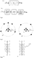
- Fig.1 shows two examples of ideal speaker positions in different speaker setups: a 22-channel speaker setup (left) and a 12-channel speaker setup (right). Every node shows the virtual position of a loudspeaker. Real speaker positions that differ in distance to the sweet spot are mapped to the virtual positions by gain and delay compensation.
- a renderer for channel based audio receives L 1 digital audio signals w 1 and processes the output to L 2 output signals w 2 .
- Fig.2 shows, in an embodiment, the integration of a renderer 21 into a reproduction chain.
- the renderer output signal w 2 is converted to an analog signal in a D/A converter 22, amplified in an amplifier 23 and reproduced by loudspeakers 24.
- the renderer 21 uses the position information of the input speaker setup and the position information of the output loudspeaker 24 setup as input to initialize the chain of processing. This is shown in Fig.3 .
- Two main processing blocks are a Mixing & Filtering block 31 and a Delay & Gain Compensation block 32.
- the speaker position information can be given e.g. in Cartesian or spherical coordinates.
- the position for the output configuration R 2 may be entered manually, or derived via microphone measurements with special test signals, or by any other method.
- the positions of the input configuration R 1 can come with the content by table entry, like an indicator e.g. for 5-channel surround. Ideal standardized loudspeaker positions [9] are assumed. The positions might also be signaled directly using spherical angle positions. A constant radius is assumed for the input configuration.
- the distances are used to derive delays and gains that are applied to the loudspeaker feeds by amplification/attenuation elements and a delay line with d l unit sample delay steps.
- d l ⁇ r 2 max ⁇ r 2 l f s / c + 0.5 ⁇ with sampling rate f s , speed of sound c ( c ⁇ 343 m / s at 20°celsius temperature) and ⁇ x + 0.5 ⁇ indicates rounding to next integer.
- the loudspeaker gains are determined by
- the task of the Delay and Gain Compensation building block 32 is to attenuate and delay speakers that are closer to the listener than other speakers, so that these closer speakers do not dominate the sound direction perceived.
- the speakers are thus arranged on a virtual sphere, as shown in Fig.1 .
- the speaker positions of the input and idealized output configurations R 1 , R ⁇ 2 are used to derive a L 2 x L 1 mixing matrix G .
- this mixing matrix is applied to the input signals to derive the speaker output signals.
- Fig.4 two general approaches exist.
- the most prominent method is Vector Base Amplitude Panning (VBAP) [1].
- the mixing matrix becomes frequency dependent ( G ( f )), as shown in Fig.4 b) . Then, a filter bank of sufficient resolution is needed, and a mixing matrix is applied to every frequency band sample according to eq.(3).
- a virtual microphone array 51 as depicted in Fig.5 is placed around the sweet spot.
- the microphone signals M 1 of sound received from the input configuration (the original directions, left-hand side) is compared to the microphone signals M 2 of sound received from the desired speaker configuration (right-hand side).
- M microphone signals receiving the sound radiated from the input configuration and be M microphone signals of the sound from the output configuration. They can be derived by and with H M , L 1 ⁇ C MxL 1 , H M , L 2 ⁇ C MxL 2 being the complex transfer function of the ideal sound radiation in the free field, assuming spherical wave or plane wave radiation.
- One problem is that a consumer's home setup is very likely to use a different placement of speakers due to real world constraints of a living room. Also the number of speakers may be different.
- the task of a renderer is thus to adapt the channel based audio signals to a new setup such that the perceived sound, loudness, timbre and spatial impression comes as close as possible to the original channel based audio as replayed on its original speaker setup, like e.g. in the mixing room.
- the present invention provides a preferably computer-implemented method of rendering multi-channel audio signals that assures replay (i.e. reproduction) of the spatial signal components with correct loudness of the signal (ie. equal to the original setup).
- replay i.e. reproduction
- a directional signal that is perceived in the original mix coming from a direction is also perceived equally loud when rendered to the new loudspeaker setup.
- filters are provided that equalize the input signals to reproduce a timbre as close as possible as it would be perceived when listening to the original setup.
- the invention relates to a method for rendering L1 channel-based input audio signals to L2 loudspeaker channels, where L1 is different from L2, as disclosed in claim 1.
- a step of mixing the delay and gain compensated input audio signal for L2 audio channels uses a mixing matrix that is generated as disclosed in claim 5.
- a corresponding apparatus according to the invention is disclosed in claim 8 and claim 12, respectively.
- the invention relates to a method for generating an energy preserving mixing matrix G for mixing input channel-based audio signals for L1 audio channels to L2 loudspeaker channels, as disclosed in claim 7.
- a corresponding apparatus for generating an energy preserving mixing matrix G according to the invention is disclosed in claim 14.
- the invention relates to a computer readable medium having stored thereon executable instructions to cause a computer to perform a method according to claim 1, or a method according to claim 7.
- the perceived sound, loudness, timbre and spatial impression of multi-channel audio replayed on an arbitrary loudspeaker setup is improved, and in particular comes as close as possible to the original channel based audio as if replayed on its original speaker setup.
- Fig.6 a shows a flow-chart of a method for rendering a first number L1 of channel-based input audio signals to a different second number L2 of loudspeaker channels according to one embodiment of the invention.
- the method for rendering L1 channel-based input audio signals w1 1 to L2 loudspeaker channels, where the number L1 of channel-based input audio signals is different from the number L2 of loudspeaker channels comprises steps of determining s60 a mix type of the L1 input audio signals, performing a first delay and gain compensation s61 on the L1 input audio signals according to the determined mix type, wherein a delay and gain compensated input audio signal with the first number L1 of channels and with a defined mix type is obtained, mixing s624 the delay and gain compensated input audio signal for the second number L2 of audio channels, wherein a remixed audio signal for the second number L2 of audio channels is obtained, clipping s63 the remixed audio signal, wherein a clipped remixed audio signal for the second number L
- the method comprises a further step of filtering s622 the delay and gain compensated input audio signal q71 having the first number L1 of channels in an equalization filter (or equalizer filter), wherein a filtered delay and gain compensated input audio signal is obtained.
- an equalization filter or equalizer filter
- the equalization filtering is in principle independent from the usage of, and can be used without, an energy preserving mixing matrix, it is particularly advantageous to use both in combination.
- Fig.6 b shows a flow-chart of a method for generating an energy preserving mixing matrix G according to one embodiment of the invention.
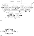
- Fig.7 shows a rendering architecture 70 according to one embodiment of the invention.
- an additional "Gain and Delay Compensation” block 71 is used for preprocessing different input setups, such as spherical, cylindrical or rectangular input setups.
- a modified "Mix & Filter” block 72 that is capable of preserving the original loudness is used.
- the "Mix & Filter” block 72 comprises an equalization filter 722.
- the "Mix & Filter” block 72 is described in more detail with respect to Fig.7b) and Fig.8 .
- a clipping prevention block 73 prevents signal overflow, which may occur due to the modified mixing matrix.
- a determining unit 75 determines a mix type of the input audio signals.
- Fig.7b shows the Mix&Filter block 72 incorporating an equalization filter 722 and a mixer unit 724.
- Fig.8 shows the structure of the equalization filter 722 in the Mix&Filter block.
- the equalization filter is in principle a filter bank with L 1 filters EF 1 ,...,EF L1 , one for each input channel. The design and characteristics of the filters are described below. All blocks mentioned may be implemented by one or more processors or processing elements that may be controlled by software instructions.
- the renderer according to the invention solves at least one of the following problems: First, new 3D audio channel based content can be mixed for at least one of spherical, rectangular or cylindrical speaker setups.
- the setup information needs to be transmitted alongside e.g. with an index for a table entry signaling the input configuration (which assumes a constant speaker radius) to be able to calculate the real input speaker positions.
- full input speaker position coordinates can be transmitted along with the content as metadata.
- a gain and delay compensation is provided for the input configuration.
- the invention provides an energy preserving mixing matrix G. Conventionally, the mixing matrix is not energy preserving.
- Energy preservation assures that the content has the same loudness after rendering, compared to the content loudness in the mixing room when using the same calibration of a replay system [6],[7],[8]. This also assures that e.g. 22-channel input or 10-channel input with equal 'Loudness, K-weighted, relative to Full Scale' (LKFS) content loudness appears equally loud after rendering.
- LKFS Full Scale'
- One advantage of the invention is that it allows generating energy (and loudness) preserving, frequency independent mixing matrices. It is noted that the same principle can also be used for frequency dependent mixing matrices, which however are not so desirable.
- a frequency independent mixing matrix is beneficial in terms of computational complexity, but often a drawback can be a in change in timbre after remix.
- simple filters are applied to each input loudspeaker channel before mixing, in order to avoid this timbre mismatching after mixing. This is the equalization filter 722.
- a method for designing such filters is disclosed below.
- an additional clipping prevention block 73 prevents such overload. In a simple realization, this can be a saturation, while in more sophisticated realizations this block is a dynamics processor for peak audio.
- the mix type determining unit 75 and the Input Gain and Delay compensation 71 are described. If the input configuration is signaled by a table entry plus mix room information, like e.g. rectangular, cylindrical or spherical, the configuration coordinates are read from special prepared tables (e.g. RAM) as spherical coordinates. If the coordinates are transmitted directly, they are converted to spherical coordinates.
- a determining unit 75 determines a mix type of the input audio signals.
- the loudspeaker gains are determined by
- Fig.7a shows a block diagram defining the descriptive variables.
- L 1 loudspeakers signals have to be processed to L 2 signals (usually, L 2 ⁇ L 1 ).
- Replay of the loudspeaker feed signals W 2 (shown as W 2 2 in Fig.7 ) should ideally be perceived with the same loudness as if listening to a replay in the mixing room, with the optimal speaker setup.
- W 1 be a matrix of L 1 loudspeaker channels (rows) and ⁇ samples (columns).
- W l,i are the matrix elements of W 1 , l denotes the speaker index, i denotes the sample index,
- fro denotes the Frobenius matrix norm, w 1 t is the t th column vector of W 1 and [ ] T denotes vector or matrix transposition.
- This energy E w gives a fair estimate of the loudness measure of a channel based audio as defined in [6],[7],[8], where the K-filter suppresses frequencies lower than 200Hz.
- loudness preservation is then obtained as follows.
- An optimal rendering matrix (also called mixing matrix or decode matrix) can be obtained as follows, according to one embodiment of the invention.
- Step 1 A conventional mixing matrix ⁇ is derived by using panning methods.
- a single loudspeaker l 1 from the set of original loudspeakers is viewed as a sound source to be reproduced by L 2 speakers of the new speaker setup.
- Preferred panning methods are VBAP [1] or robust panning [2] for a constant frequency (i.e. a known technology can be used for this step).
- the modified speaker positions R ⁇ 2 , R ⁇ 1 are used, R ⁇ 2 for the output configuration and R ⁇ 1 for the virtual source directions.
- Step3 A new matrix ⁇ is formed from S where the diagonal elements are replaced by a value of one, but very low valued singular values are replaced by zeros.
- a threshold in the range of -10dB ... -30dB or less is usually selected (e.g. -20dB is a typical value). The threshold becomes apparent from actual numbers in realistic examples, since there will occur two groups of diagonal elements: elements with larger value and elements with considerably smaller value. The threshold is for distinguishing among these two groups.
- fro ⁇ L 1 , a scaling factor compensates the loss of energy during down-mixing.
- a singularity matrix is described in the following.
- the singularity matrix is processed by setting the coefficients s 1 ,s 2 ,...,s L to be either 1 or 0, depending whether each coefficient is above a threshold of e.g. 0.06*s max .
- a threshold factor is exemplary 0.06, but can be (when expressed in decibel) e.g. in the range of -10dB or lower.
- the number of its non-zero diagonal coefficients is two.
- Equalization Filter 722 is described.
- timbre may change.
- a sound originally coming from above is now reproduced using only speakers on the horizontal plane.
- the task of the equalization filter is to minimize this timbre mismatch and maximize energy preservation.
- Individual filters F l are applied to each channel of the L 1 channels of the input configuration before applying the mixing matrix, as shown in Fig.7b ). The following shows the theoretical deviation and describes how the frequency response of the filters is derived.
- the b l of eq.(30) are frequency-dependent gain factors or scaling factors, and can be used as coefficients of the equalization filter 722 for each frequency band, since b l and H M , L 2 H H M , L 2 are frequency-dependent.
- Virtual microphone array radius and transfer function are taken into account as follows. To match the perceptual timbre effects of humans best, a microphone radius r M of 0.09m is selected (the mean diameter of a human head is commonly assumed to be about 0.18m). M ⁇ L 1 virtual microphones are placed on a sphere or radius r M around the origin (sweet spot, listening position). Suitable positions are known [11]. One additional virtual microphone is added at the origin of the coordinate system.
- the transfer matrices H M , L 2 ⁇ C MxL 2 are designed using a plane wave or spherical wave model. For the latter, the amplitude attenuation effects can be neglected due to the gain and delay compensation stages.
- Let h m,l be an abstract matrix element of the transfer matrices H M.L , for the free field transfer function from speaker l to microphone m (which also indicate column and row indices of the matrices).
- the frequency response B resp ⁇ C L 1 xF N of the filter is calculated using a loop over F N discrete frequencies and a loop over all input configuration speakers L 1 :
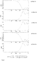
- the filter responses can be derived from the frequency responses B resp (l, f) using standard technologies. Typically, it is possible to derive a FIR filter design of order equal or less than 64, or IIR filter designs using cascaded bi-quads with even less computational complexity. Fig.9 and 10 show design examples.
- Fig.9 example frequency responses of filters for a remix of 5-channels ITU setup [9] (L,R,C,Ls,Rs) to +/- 30° 2-channel stereo, and an exemplary resulting 2x5 mixing matrix G are shown.
- the mixing matrix was derived as described above, using [2] for 500Hz.
- a plane wave model was used for the transfer functions.
- two of the filters (upper row, for two of the channels) have in principle low-pass (LP) characteristics
- three of the filters lower rows, for the remaining three channels
- HP high-pass
- the filters do not have ideal HP or LP characteristics, because together they form an equalization filter (or equalization filter bank).
- not all the filters have substantially same characteristics, so that at least one LP and at least one HP filter is employed for the different channels.
- Fig.10 example responses of filters for a remix of 22 channels of the 22.2 NHK setup [10] to ITU 5-channel surround [9] are shown.
- Fig.10b the three filters of the first row of Fig.10a ) are exemplarily shown. Also a resulting 5x22 mixing matrix G is shown, as obtained by the present invention.
- the present invention can be used to adjust audio channel based content with arbitrary defined L 1 loudspeaker positions to enable replay to L 2 real-world loudspeaker positions.
- the invention relates to a method of rendering channel based audio of L 1 channels to L 2 channels, wherein a loudness & energy preserving mixing matrix is used.
- the matrix is derived by singular value decomposition, as described above in the section about design of optimal rendering matrices.
- the singular value decomposition is applied to a conventionally derived mixing matrix.
- the matrix is scaled according to eq.(19) or (19') by a factor of (for L 1 ⁇ L 2 ), or by a factor of (for L 1 ⁇ L 2 ).
- the invention relates to a method of filtering the L 1 input channels before applying the mixing matrix.
- input signals that use different speaker positions are mapped to a spherical projection in a Delay & Gain Compensation block 71.
- equalization filters are derived from the frequency responses as described above.
- a device for rendering a first number L 1 of channels of channel-based audio signals (or content) to a second number L 2 of channels of channel-based audio signals (or content) is assembled out of at least the following building blocks/ processing blocks:
- One advantage of the improved mixing mode matrix G is that the perceived sound, loudness, timbre and spatial impression of multi-channel audio replayed on an arbitrary loudspeaker setup practically equals that of the original speaker setup. Thus, it is not required any more to locate loudspeakers strictly according to a predefined setup for enjoying a maximum sound quality and optimal perception of directional sound signals.
- an apparatus for rendering L1 channel-based input audio signals to L2 loudspeaker channels comprises at least one of each of a determining unit for determining a mix type of the L1 input audio signals, wherein possible mix types include at least one of spherical, cylindrical and rectangular; a first delay and gain compensation unit for performing a first delay and gain compensation on the L1 input audio signals according to the determined mix type, wherein a delay and gain compensated input audio signal with L1 channels and with a defined mix type is obtained; a mixer unit for mixing the delay and gain compensated input audio signal for L2 audio channels, wherein a remixed audio signal for L2 audio channels is obtained; a clipping unit for clipping the remixed audio signal, wherein a clipped remixed audio signal for L2 audio channels is obtained; and a second delay and gain compensation unit for performing a second delay and gain compensation on the clipped remixed audio signal for L2 audio channels, wherein L2 loudspeaker channels are obtained.
- the invention is usable for content loudness level calibration. If the replay levels of a mixing facility and of presentation venues are setup in the manner as described, switching between items or programs is possible without further level adjustments. For channel based content, this is simply achieved if the content is tuned to a pleasant loudness level at the mixing site.
- the reference for such pleasant listening level can either be the loudness of the whole item itself or an anchor signal.
- LUFS Loudness Units Full Scale
- the level is selected in relation to this signal. This is useful for 'long form content' such as film sound, live recordings and broadcasts. An additional requirement, extending the pleasant listening level, is intelligibility of the spoken word here.
- the content may be normalized related a loudness measure, such as defined in ATSC A/85 [8]. First parts of the content are identified as anchor parts. Then a measure as defined in [7] is computed or these signals and a gain factor to reach the target loudness is determined. The gain factor is used to scale the complete item. Unfortunately, again the maximum number of channels supported is restricted to five.
- a loudspeaker is meant.
- a speaker or loudspeaker is a synonym for any sound emitting device. It is noted that usually where speaker directions are mentioned in the specification or the claims, also speaker positions can be equivalently used (and vice versa).
- EEEs enumerated example embodiments
Landscapes
- Physics & Mathematics (AREA)
- Engineering & Computer Science (AREA)
- Acoustics & Sound (AREA)
- Signal Processing (AREA)
- Algebra (AREA)
- General Physics & Mathematics (AREA)
- Mathematical Analysis (AREA)
- Mathematical Optimization (AREA)
- Mathematical Physics (AREA)
- Pure & Applied Mathematics (AREA)
- Theoretical Computer Science (AREA)
- Stereophonic System (AREA)
Description
- This invention relates to a method for rendering multi-channel audio signals, and an apparatus for rendering multi-channel audio signals. In particular, the invention relates to a method and apparatus for rendering multi-channel audio signals for L1 channels to a different number L2 of loudspeaker channels.
- New 3D channel based Audio formats provide audio mixes for loudspeaker channels that not only surround the listening position, but also include channels positioned above (height) and below in respect to the listening position (sweet spot). The mixes are suited for a special positioning of these speakers. Common formats are 22.2 (i.e. 22 channels) or 11.1 (i.e. 11 channels).
-
Fig.1 shows two examples of ideal speaker positions in different speaker setups: a 22-channel speaker setup (left) and a 12-channel speaker setup (right). Every node shows the virtual position of a loudspeaker. Real speaker positions that differ in distance to the sweet spot are mapped to the virtual positions by gain and delay compensation. - A renderer for channel based audio receives L1 digital audio signals w1 and processes the output to L2 output signals w2 .
Fig.2 shows, in an embodiment, the integration of arenderer 21 into a reproduction chain. The renderer output signal w2 is converted to an analog signal in a D/A converter 22, amplified in anamplifier 23 and reproduced byloudspeakers 24. - The
renderer 21 uses the position information of the input speaker setup and the position information of theoutput loudspeaker 24 setup as input to initialize the chain of processing. This is shown inFig.3 . Two main processing blocks are a Mixing &Filtering block 31 and a Delay &Gain Compensation block 32. - The speaker position information can be given e.g. in Cartesian or spherical coordinates. The position for the output configuration R 2 may be entered manually, or derived via microphone measurements with special test signals, or by any other method. The positions of the input configuration R 1 can come with the content by table entry, like an indicator e.g. for 5-channel surround. Ideal standardized loudspeaker positions [9] are assumed. The positions might also be signaled directly using spherical angle positions. A constant radius is assumed for the input configuration.
- Let R 2 = [r2 1, r2 2,..., r2 L
2 ] with
- The distances are used to derive delays and gainsthat are applied to the loudspeaker feeds by amplification/attenuation elements and a delay line with dl unit sample delay steps. First, the maximal distance between a speaker and the sweet spot is determined:


- For each speaker feed the delay is calculated by:
 are determined by

- The task of the Delay and Gain Compensation
building block 32 is to attenuate and delay speakers that are closer to the listener than other speakers, so that these closer speakers do not dominate the sound direction perceived. The speakers are thus arranged on a virtual sphere, as shown inFig.1 . The Mix &Filter block 31 now can use virtual speaker positions
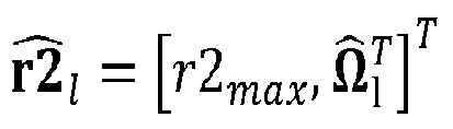
- In an initialization phase, the speaker positions of the input and idealized output configurations R 1, R̂ 2 are used to derive a L 2 x L 1 mixing matrix G . During the process of rendering, this mixing matrix is applied to the input signals to derive the speaker output signals. As shown in
Fig.4 , two general approaches exist. In the first approach shown inFig.4 a) , the mixing matrix is independent from the audio frequency and the output is derived by:


- In the second approach, the mixing matrix becomes frequency dependent ( G (f)), as shown in
Fig.4 b) . Then, a filter bank of sufficient resolution is needed, and a mixing matrix is applied to every frequency band sample according to eq.(3). - Examples for the latter approach are known [2],[3],[4]. For deriving the mixing matrix, the following approach is used: A
virtual microphone array 51 as depicted inFig.5 , is placed around the sweet spot. The microphone signals M1 of sound received from the input configuration (the original directions, left-hand side) is compared to the microphone signals M2 of sound received from the desired speaker configuration (right-hand side). Let



2 can be derived as:
- Usually this produces non-satisfying results, and [2] and [5] present more sophisticated approached to solve eq.(6) for G .
- Further, there is a completely different way of signal adaptive rendering, where the directional signals of the incoming audio content is extracted and rendered like audio objects. The residual signal is panned and de-correlated to the output speakers. This kind of audio rendering is much more expensive in terms of computational complexity, and often not free from artifacts. Signal adaptive rendering is not used and only mentioned here for completeness.
- One problem is that a consumer's home setup is very likely to use a different placement of speakers due to real world constraints of a living room. Also the number of speakers may be different. The task of a renderer is thus to adapt the channel based audio signals to a new setup such that the perceived sound, loudness, timbre and spatial impression comes as close as possible to the original channel based audio as replayed on its original speaker setup, like e.g. in the mixing room.
- The present invention provides a preferably computer-implemented method of rendering multi-channel audio signals that assures replay (i.e. reproduction) of the spatial signal components with correct loudness of the signal (ie. equal to the original setup). Thus, a directional signal that is perceived in the original mix coming from a direction is also perceived equally loud when rendered to the new loudspeaker setup. In addition, filters are provided that equalize the input signals to reproduce a timbre as close as possible as it would be perceived when listening to the original setup.
- In one aspect, the invention relates to a method for rendering L1 channel-based input audio signals to L2 loudspeaker channels, where L1 is different from L2, as disclosed in
claim 1. In one embodiment, a step of mixing the delay and gain compensated input audio signal for L2 audio channels uses a mixing matrix that is generated as disclosed inclaim 5. A corresponding apparatus according to the invention is disclosed inclaim 8 and claim 12, respectively. - In one aspect, the invention relates to a method for generating an energy preserving mixing matrix G for mixing input channel-based audio signals for L1 audio channels to L2 loudspeaker channels, as disclosed in
claim 7. A corresponding apparatus for generating an energy preserving mixing matrix G according to the invention is disclosed inclaim 14. In one aspect, the invention relates to a computer readable medium having stored thereon executable instructions to cause a computer to perform a method according toclaim 1, or a method according toclaim 7. In one embodiment of the invention, a computer-implemented method for generating an energy preserving mixing matrix G for mixing input channel-based audio signals for L1 audio channels to L2 loudspeaker channels comprises computer-executed steps of obtaining a first mixing matrix Ĝ from virtual source directions
 non-zero diagonal elements, determining from the number of non-zero diagonal elements a scaling factor a according to


- Further objects, features and advantages of the invention will become apparent from a consideration of the following description and the appended claims when taken in connection with the accompanying drawings.
- Exemplary embodiments of the invention are described with reference to the accompanying drawings, which show in
- Fig.1
- two examples of loudspeaker setups;
- Fig.2
- a known general structure for rendering content for a new loudspeaker setup;
- Fig.3
- a general known structure for channel based audio rendering;
- Fig.4
- two approaches to mix L1 channels to L2 output channels, using a) a frequency-independent mixing matrix G , and b) a frequency dependent mixing matrix G ( f );
- Fig.5
- a virtual microphone array used to compare the sound radiated from the original setup (input configuration) to a desired output configuration;
- Fig.6 a)
- a flow-chart of a method for rendering L1 channel-based input audio signals to L2 loudspeaker channels according to the invention;
- Fig.6 b)
- a flow-chart of a method for generating an energy preserving mixing matrix G according to the invention;
- Fig.7
- a rendering architecture according to one embodiment of the invention;
- Fig.8
- the structure of one embodiment of a filter in the Mix&Filter block;
- Fig.9
- exemplary frequency responses for a remix of five channels; and
- Fig.10
- exemplary frequency responses for a remix of twenty-two channels.
-
Fig.6 a) shows a flow-chart of a method for rendering a first number L1 of channel-based input audio signals to a different second number L2 of loudspeaker channels according to one embodiment of the invention. The method for rendering L1 channel-based input audio signals w11 to L2 loudspeaker channels, where the number L1 of channel-based input audio signals is different from the number L2 of loudspeaker channels, comprises steps of determining s60 a mix type of the L1 input audio signals, performing a first delay and gain compensation s61 on the L1 input audio signals according to the determined mix type, wherein a delay and gain compensated input audio signal with the first number L1 of channels and with a defined mix type is obtained, mixing s624 the delay and gain compensated input audio signal for the second number L2 of audio channels, wherein a remixed audio signal for the second number L2 of audio channels is obtained, clipping s63 the remixed audio signal, wherein a clipped remixed audio signal for the second number L2 of audio channels is obtained, and performing a second delay and gain compensation s64 on the clipped remixed audio signal for the second number L2 of audio channels, wherein the second number L2 of loudspeaker channels w22 are obtained. Possible mix types include at least one of spherical, cylindrical and rectangular (or, more general, cubic). In one embodiment, the method comprises a further step of filtering s622 the delay and gain compensated input audio signal q71 having the first number L1 of channels in an equalization filter (or equalizer filter), wherein a filtered delay and gain compensated input audio signal is obtained. While the equalization filtering is in principle independent from the usage of, and can be used without, an energy preserving mixing matrix, it is particularly advantageous to use both in combination. -
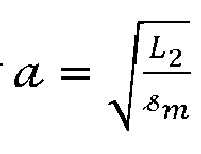
Fig.6 b) shows a flow-chart of a method for generating an energy preserving mixing matrix G according to one embodiment of the invention. The method s710 for obtaining an energy preserving mixing matrix G for mixing input channel-based audio signals for a first number L1 of audio channels to a second number L2 of loudspeaker channels comprises steps of obtaining s711 a first mixing matrix Ĝ from virtual source positions/directions 
directions 


 of diagonal elements that are set to one in the quantized singularity matrix Ŝ, determining s715 a scaling factor a according to

-
Fig.7 shows arendering architecture 70 according to one embodiment of the invention. In the rendering architecture according to the embodiment shown inFig.7a ), an additional "Gain and Delay Compensation"block 71 is used for preprocessing different input setups, such as spherical, cylindrical or rectangular input setups. Further, a modified "Mix & Filter"block 72 that is capable of preserving the original loudness is used. In one embodiment, the "Mix & Filter"block 72 comprises anequalization filter 722. The "Mix & Filter"block 72 is described in more detail with respect toFig.7b) and Fig.8 . Aclipping prevention block 73 prevents signal overflow, which may occur due to the modified mixing matrix. A determiningunit 75 determines a mix type of the input audio signals. -
Fig.7b ) shows theMix&Filter block 72 incorporating anequalization filter 722 and amixer unit 724.Fig.8 shows the structure of theequalization filter 722 in the Mix&Filter block. The equalization filter is in principle a filter bank with L1 filters EF1,...,EFL1, one for each input channel. The design and characteristics of the filters are described below. All blocks mentioned may be implemented by one or more processors or processing elements that may be controlled by software instructions. - The renderer according to the invention solves at least one of the following problems: First, new 3D audio channel based content can be mixed for at least one of spherical, rectangular or cylindrical speaker setups. The setup information needs to be transmitted alongside e.g. with an index for a table entry signaling the input configuration (which assumes a constant speaker radius) to be able to calculate the real input speaker positions. In an alternative embodiment, full input speaker position coordinates can be transmitted along with the content as metadata. To use mixing matrices independent of the mixing type, a gain and delay compensation is provided for the input configuration. Second, the invention provides an energy preserving mixing matrix G. Conventionally, the mixing matrix is not energy preserving. Energy preservation assures that the content has the same loudness after rendering, compared to the content loudness in the mixing room when using the same calibration of a replay system [6],[7],[8]. This also assures that e.g. 22-channel input or 10-channel input with equal 'Loudness, K-weighted, relative to Full Scale' (LKFS) content loudness appears equally loud after rendering.
- One advantage of the invention is that it allows generating energy (and loudness) preserving, frequency independent mixing matrices. It is noted that the same principle can also be used for frequency dependent mixing matrices, which however are not so desirable. A frequency independent mixing matrix is beneficial in terms of computational complexity, but often a drawback can be a in change in timbre after remix. In one embodiment, simple filters are applied to each input loudspeaker channel before mixing, in order to avoid this timbre mismatching after mixing. This is the
equalization filter 722. A method for designing such filters is disclosed below. - Energy preserving rendering has a drawback that signal overload is possible for peak audio signal components. In one embodiment of the present invention, an additional
clipping prevention block 73 prevents such overload. In a simple realization, this can be a saturation, while in more sophisticated realizations this block is a dynamics processor for peak audio. - In the following, details about the mix
type determining unit 75 and the Input Gain andDelay compensation 71 are described. If the input configuration is signaled by a table entry plus mix room information, like e.g. rectangular, cylindrical or spherical, the configuration coordinates are read from special prepared tables (e.g. RAM) as spherical coordinates. If the coordinates are transmitted directly, they are converted to spherical coordinates. A determiningunit 75 determines a mix type of the input audio signals. Let R 1 = [r1 1, r1 2, ..., r1 L1 ] with
- In a first step the maximum radius is detected: r1max = max([r11,... r1L
2 ]. Because only relative differences are of interest for this building block, the radii are r1l scaled by r2 max that is available from the gain and delay compensation initialization of the output configuration:
- The number of delay tabs ďl and the gain valuesfor every speaker are calculated as follows with


- The loudspeaker gainsare determined by


- The Mix & Filter block now can use virtual speaker positions


- In the following, the Mixing Matrix design is explained.
- First, the energy of the speaker signals and perceived loudness are discussed.
-
Fig.7a ) shows a block diagram defining the descriptive variables. L 1 loudspeakers signals have to be processed to L 2 signals (usually, L 2 ≤ L 1). Replay of the loudspeaker feed signals W 2 (shown as W 22 inFig.7 ) should ideally be perceived with the same loudness as if listening to a replay in the mixing room, with the optimal speaker setup. Let W 1 be a matrix of L 1 loudspeaker channels (rows) and τ samples (columns). - The energy of the signal W 1 , of the τ-time sample block is defined as follows:

- Here Wl,i are the matrix elements of W 1 , l denotes the speaker index, i denotes the sample index, || || fro denotes the Frobenius matrix norm, w 1
t is the t th column vector of W 1 and [ ] T denotes vector or matrix transposition. - This energy E w gives a fair estimate of the loudness measure of a channel based audio as defined in [6],[7],[8], where the K-filter suppresses frequencies lower than 200Hz.
- Mixing of the signals W 1 provides signals W 2 . The signal energy after mixing becomes:

- The process of rendering is assumed to be performed by a mixing matrix G , signals W 2 are derived from W 1 as follows:

- Evaluating E w
2 and using the columns vector decomposition of W 1 = [ w 11 ,.., w 1 t ,.., w 1 τ ] with w1 t = [w 1t,1 ,..,w 1 t,l ,.., w 1 t,L ] T then leads to:
- In one embodiment, loudness preservation is then obtained as follows.
- The loudness of the original signal mix is preserved in the new rendered signal if:

- From eq.(14) it becomes apparent that mixing matrix M needs to be orthogonal and

- An optimal rendering matrix (also called mixing matrix or decode matrix) can be obtained as follows, according to one embodiment of the invention.
- Step 1: A conventional mixing matrix Ĝ is derived by using panning methods. A single loudspeaker l 1 from the set of original loudspeakers is viewed as a sound source to be reproduced by L 2 speakers of the new speaker setup. Preferred panning methods are VBAP [1] or robust panning [2] for a constant frequency (i.e. a known technology can be used for this step). To determine the mixing matrix Ĝ , the modified speaker positions R̂ 2, R̂ 1 are used, R̂ 2 for the output configuration and R̂ 1 for the virtual source directions. Step 2: Using compact singular value decomposition, the mixing matrix is expressed as a product of three matrices:


- Note that this holds for the case of L 2 ≤ L 1, (remix L 2 = L 1, downmix L 2 < L 1). For the case of upmix (L 2 > L 1), L 2 needs to be replaced by L 1 in this section.
- Step3: A new matrix Ŝ is formed from S where the diagonal elements are replaced by a value of one, but very low valued singular values
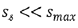
- For most speaker settings, the number of non-zero diagonal elementsis


- Letdenote the last singular value to be replaced by one. Then the mixing matrix G is determined by:


- The scaling factor is derived from: G T G = a 2 VŜ 2 VT = a 2 VVT , where VVT hasEigenvalues equal to one. That means that

 signals will reduce the energy, unless

1 | fro =

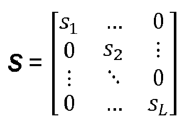
- As an example, processing of a singularity matrix is described in the following. E.g., an initial (conventional) mixing matrix for L loudspeakers is decomposed using compact singular value decomposition according to eq.(17): Ĝ = U S VT . The singularity matrix S is square (with LxL elements, L=min{L1,L2} for compact singular value decomposition) and is a diagonal matrix of the form
- For a case with e.g. L=5 and e.g. only s1 and s2 being above the threshold and s3, s4 and s5 being below the threshold, the resulting processed (or "quantized") singularity matrix Ŝ is
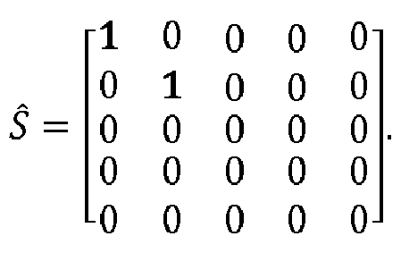 is two.
- In the following, the
Equalization Filter 722 is described. - When mixing between different 3D setups, and especially when mixing from 3D setups to 2D setups, timbre may change. E.g. for 3D to 2D, a sound originally coming from above is now reproduced using only speakers on the horizontal plane. The task of the equalization filter is to minimize this timbre mismatch and maximize energy preservation. Individual filters Fl are applied to each channel of the L1 channels of the input configuration before applying the mixing matrix, as shown in
Fig.7b ). The following shows the theoretical deviation and describes how the frequency response of the filters is derived. - A model according to
Fig.7 and eqs. (4) and (5) is used. Both equations are reprinted here for convenience:


- Instead of equating eqs.(4) and (5), as mentioned in the background section, we will equate the energies. And since we want to equalize for the sound of the speaker directions of the input configuration, we can solve the considerations for each input speaker at a time (loop over L 1).
- The energy measured at the virtual microphones for the input setup, if only one speaker l is active, is given by

1 and w 1 l one row of W 1 , i.e. the time signal of speaker l with τ samples. Rewriting the Frobenius norm analog to eq.(11), we can further evaluate eq.(22) to:


- The measures at the virtual microphones after mixing are given by


- We can now equate the energies according to eq.(24) and eq.(29) respectively, and solve for bl for each frequency f:

- The bl of eq.(30) are frequency-dependent gain factors or scaling factors, and can be used as coefficients of the
equalization filter 722 for each frequency band, since bl and
- In the following, practical filter design for the
equalization filter 722 is described. - Virtual microphone array radius and transfer function are taken into account as follows. To match the perceptual timbre effects of humans best, a microphone radius rM of 0.09m is selected (the mean diameter of a human head is commonly assumed to be about 0.18m). M ≫ L1 virtual microphones are placed on a sphere or radius rM around the origin (sweet spot, listening position). Suitable positions are known [11]. One additional virtual microphone is added at the origin of the coordinate system.
- The transfer matrices



- The frequency response

- Calculate G according to the above description (3-step procedure for design of optimal rendering matrices):


- The filter responses can be derived from the frequency responses B resp (l, f) using standard technologies. Typically, it is possible to derive a FIR filter design of order equal or less than 64, or IIR filter designs using cascaded bi-quads with even less computational complexity.
Fig.9 and10 show design examples. - In
Fig.9 , example frequency responses of filters for a remix of 5-channels ITU setup [9] (L,R,C,Ls,Rs) to +/- 30° 2-channel stereo, and an exemplary resulting 2x5 mixing matrix G are shown. The mixing matrix was derived as described above, using [2] for 500Hz. A plane wave model was used for the transfer functions. As shown, two of the filters (upper row, for two of the channels) have in principle low-pass (LP) characteristics, and three of the filters (lower rows, for the remaining three channels) have in principle high-pass (HP) characteristics. It is intended that the filters do not have ideal HP or LP characteristics, because together they form an equalization filter (or equalization filter bank). Generally, not all the filters have substantially same characteristics, so that at least one LP and at least one HP filter is employed for the different channels. - In
Fig.10 , example responses of filters for a remix of 22 channels of the 22.2 NHK setup [10] to ITU 5-channel surround [9] are shown. InFig.10b ), the three filters of the first row ofFig.10a ) are exemplarily shown. Also a resulting 5x22 mixing matrix G is shown, as obtained by the present invention. - The present invention can be used to adjust audio channel based content with arbitrary defined L 1 loudspeaker positions to enable replay to L 2 real-world loudspeaker positions. In one aspect, the invention relates to a method of rendering channel based audio of L 1 channels to L 2 channels, wherein a loudness & energy preserving mixing matrix is used. The matrix is derived by singular value decomposition, as described above in the section about design of optimal rendering matrices. In one embodiment, the singular value decomposition is applied to a conventionally derived mixing matrix.
- In one embodiment, the matrix is scaled according to eq.(19) or (19') by a factor of


- Conventional matrices can be derived by using various panning methods, e.g. VBAP or robust panning. Further, conventional matrices use idealized input and output speaker positions (spherical projection, see above). Therefore, in one aspect, the invention relates to a method of filtering the L 1 input channels before applying the mixing matrix. In one embodiment, input signals that use different speaker positions are mapped to a spherical projection in a Delay &
Gain Compensation block 71. - In one embodiment, equalization filters are derived from the frequency responses as described above.
- In one embodiment, a device for rendering a first number L 1 of channels of channel-based audio signals (or content) to a second number L 2 of channels of channel-based audio signals (or content) is assembled out of at least the following building blocks/ processing blocks:
- input (and output) gain and delay compensation blocks 71,74, having the purpose to map the input and output speaker positions to a virtual sphere. Such spherical structure is required for the above-described mixing matrix to be applicable;
-
equalization filters 722 derived by the method described above for filtering the first number L 1 of channels after input gain and delay compensation; - a
mixer unit 72 for mixing the first number L 1 of input channels to the second number L 2 of output channels by applying the energy preservingmixing matrix 724 as derived by the method described above. The equalization filters 722 may be part of themixer unit 72, or may be a separate module; - a signal overflow detection and clipping prevention block (or clipping unit) 73 to prevent signal overload to the signals of L 2 channels; and
- an output gain and delay correction block 74 (already mentioned above).
- In one embodiment, a method for obtaining or generating an energy preserving mixing matrix G for mixing L1 input audio channels to L2 output channels comprises steps of obtaining s711 a first mixing matrix Ĝ , performing s712 a singular value decomposition on the first mixing matrix Ĝ to obtain a singularity matrix S, processing s713 the singularity matrix S to obtain a processed singularity matrix Ŝ , determining s715 a scaling factor a, and calculating s716 an improved mixing matrix G according to G = a U Ŝ VT . One advantage of the improved mixing mode matrix G is that the perceived sound, loudness, timbre and spatial impression of multi-channel audio replayed on an arbitrary loudspeaker setup practically equals that of the original speaker setup. Thus, it is not required any more to locate loudspeakers strictly according to a predefined setup for enjoying a maximum sound quality and optimal perception of directional sound signals.
- In one embodiment, an apparatus for rendering L1 channel-based input audio signals to L2 loudspeaker channels, where L1 is different from L2, comprises at least one of each of a determining unit for determining a mix type of the L1 input audio signals, wherein possible mix types include at least one of spherical, cylindrical and rectangular;
a first delay and gain compensation unit for performing a first delay and gain compensation on the L1 input audio signals according to the determined mix type, wherein a delay and gain compensated input audio signal with L1 channels and with a defined mix type is obtained;
a mixer unit for mixing the delay and gain compensated input audio signal for L2 audio channels, wherein a remixed audio signal for L2 audio channels is obtained;
a clipping unit for clipping the remixed audio signal, wherein a clipped remixed audio signal for L2 audio channels is obtained; and
a second delay and gain compensation unit for performing a second delay and gain compensation on the clipped remixed audio signal for L2 audio channels, wherein L2 loudspeaker channels are obtained. - Further, in one embodiment of the invention, an apparatus for obtaining an energy preserving mixing matrix G for mixing input channel-based audio signals for L1 audio channels to L2 loudspeaker channels comprises at least one processing element and memory for storing software instructions for implementing
a first calculation module for obtaining a first mixing matrix Ĝ from virtual source directions

a singular value decomposition module for performing a singular value decomposition on the first mixing matrix Ĝ according to Ĝ = U S VT , wherein


a processing module processing the singularity matrix S , wherein a quantized singularity matrix Ŝ is obtained with diagonal elements that are above a threshold set to one and diagonal elements that are below a threshold set to zero;
a counting module for determining a numberof diagonal elements that are set to one in the quantized singularity matrix Ŝ;
a second calculation module for determining a scaling factor a according to
a third calculation module for calculating a mixing matrix G according to
- Advantageously, the invention is usable for content loudness level calibration. If the replay levels of a mixing facility and of presentation venues are setup in the manner as described, switching between items or programs is possible without further level adjustments. For channel based content, this is simply achieved if the content is tuned to a pleasant loudness level at the mixing site. The reference for such pleasant listening level can either be the loudness of the whole item itself or an anchor signal.
- If the reference is the whole item itself, this is useful for 'short form content', if the content is stored as a file. Besides adjustment by listening, a measurement of the loudness in Loudness Units Full Scale (LUFS) according to EBU R128 [6] can be used to loudness adjust the content. Another name for LUFS is 'Loudness, K-weighted, relative to Full Scale' from ITU-R BS.1770 [7] (1 LUFS = 1 LKFS). Unfortunately [6] only supports content for setups up to 5-channel surround. It has not been investigated yet if loudness measures of 22-channel files correlate with perceived loudness if all 22 channels are factored by equal channel weights of one.
- If the above-mentioned reference is an anchor signal, such as in a dialog, the level is selected in relation to this signal. This is useful for 'long form content' such as film sound, live recordings and broadcasts. An additional requirement, extending the pleasant listening level, is intelligibility of the spoken word here. Again, besides an adjustment by listening, the content may be normalized related a loudness measure, such as defined in ATSC A/85 [8]. First parts of the content are identified as anchor parts. Then a measure as defined in [7] is computed or these signals and a gain factor to reach the target loudness is determined. The gain factor is used to scale the complete item. Unfortunately, again the maximum number of channels supported is restricted to five.
- Out of artistic considerations, content should be adjusted by listening at the mixing studio. Loudness measures can be used as a support and to show that a specified loudness is not exceeded. The energy E w according to eq.(11) gives a fair estimate of the perceived loudness of such an anchor signal for frequencies over 200Hz. Because the K-filter suppresses frequencies lower than 200Hz [5], E w is approximately proportional to the loudness measure.
- It is noted that when a "speaker" is mentioned herein, a loudspeaker is meant. Generally, a speaker or loudspeaker is a synonym for any sound emitting device. It is noted that usually where speaker directions are mentioned in the specification or the claims, also speaker positions can be equivalently used (and vice versa).
- While there has been shown, described, and pointed out fundamental novel features of the present invention as applied to preferred embodiments thereof, it will be understood that various omissions and substitutions and changes in the apparatus and method described, in the form and details of the devices disclosed, and in their operation, may be made by those skilled in the art without departing from the spirit of the present invention. E.g., although in the above embodiments, the number L1 of channels of the channel-based input audio signals is usually different from the number L2 of loudspeaker channels, it is clear that the invention can also be applied in cases where both numbers are equal (so-called remix). This may be useful in several cases, e.g. if directional sound should be optimized for any irregular loudspeaker setup. Further, it is generally advantageous to use an energy preserving rendering matrix for rendering. It is expressly intended that all combinations of those elements that perform substantially the same function in substantially the same way to achieve the same results are within the scope of the invention.
- Substitutions of elements from one described embodiment to another are also fully intended and contemplated. It will be understood that the present invention has been described purely by way of example, and modifications of detail can be made without departing from the scope of the invention.
- Each feature disclosed in the description and (where appropriate) the claims and drawings may be provided independently or in any appropriate combination. Features may, where appropriate be implemented in hardware, software, or a combination of the two. Connections may, where applicable, be implemented as wireless connections or wired, not necessarily direct or dedicated, connections.
- Reference numerals appearing in the claims are by way of illustration only and shall have no limiting effect on the scope of the claims.
-
- [1] Pulkki, V., "Virtual Sound Source Positioning Using Vector Base Amplitude Panning", J. Audio Eng. Soc., vol. 45, pp. 456-466 (1997 June).
- [2] Poletti, M., "Robust two-dimensional surround sound reproduction for non-uniform loudspeaker layouts". J. Audio Eng. Soc., 55(7/8):598-610, July/August 2007.
- [3] O. Kirkeby and P. A. Nelson, "Reproduction of plane wave sound fields," J. Acoust. Soc. Am. 94 (5), 2992-3000 (1993).
- [4] Fazi, F.; Yamada, T; Kamdar, S.; Nelson P.A.; Otto, P., "Surround Sound Panning Technique Based on a Virtual Microphone Array", AES Convention:128 (May 2010)Paper Number:8119
- [5] Shin, M.; Fazi, F.; Seo, J.; Nelson, P. A. "Efficient 3-D Sound Field Reproduction", AES Convention:130 (May 2011)Paper Number:8404
- [6] EBU Technical Recommendation R128, "Loudness Normalization and Permitted Maximum Level of Audio Signals", Geneva, 2010 [http://tech.ebu.ch/docs/r/r128.pdf]
- [7] ITU-R Recommendation BS.1770-2, "Algorithms to measure audio programme loudness and true-peak audio level", Geneva, 2011.
- [8] ATSC A/85, "Techniques for Establishing and Maintaining Audio Loudness for Digital Television", Advanced Television Systems Committee, Washington, D.C., July 25, 2011.
- [9] ITU-R BS 775-1 (1994)
- [10] Hamasaki, K.; Nishiguchi,T.; Okumura, R.; Nakayama, Y. ; Ando, A. "A 22.2 multichannel sound system for ultrahigh-definition TV (UHDTV)," SMPTE Motion Imaging J., pp.40-49, Apr. 2008.
- [11] Jörg Fliege and Ulrike Maier. A two-stage approach for computing cubature formulae for the sphere. Technical report, Fachbereich Mathematik, Universität Dortmund, 1999. Node numbers & report can be found at http://www.personal.soton.ac.uk/jf1w07/nodes/nodes.html
- Various aspects of the present invention may be appreciated from the following enumerated example embodiments (EEEs):
- 1. A method for rendering L1 channel-based input audio signals (w11) to L2 loudspeaker channels, where L1 is different from L2, the method comprising steps of
- determining (s60) a mix type of the L1 input audio signals, wherein possible mix types include at least one of spherical, cylindrical and rectangular;
- performing a first delay and gain compensation (s61) on the L1 input audio signals according to the determined mix type, wherein a delay and gain compensated input audio signal (q71) with L1 channels and with a defined mix type is obtained;
- mixing (s624) the delay and gain compensated input audio signal for L2 audio channels, wherein a remixed audio signal for L2 audio channels is obtained;
- clipping (s63) the remixed audio signal, wherein a clipped remixed audio signal for L2 audio channels is obtained; and
- performing a second delay and gain compensation (s64) on the clipped remixed audio signal for L2 audio channels, wherein L2 loudspeaker channels (w22) are obtained.
- 2. Method according to
EEE 1, further comprising a step of filtering (s622) the delay and gain compensated input audio signal (q71) with L1 channels, wherein a filtered delay and gain compensated input audio signal is obtained, and wherein the step of mixing (s624) uses the filtered delay and gain compensated input audio signal. - 3. Method according to
EEE 2, wherein the filtering (s622) of the delay and gain compensated input audio signal with L1 channels uses an equalizer filter with different types of filters for the channels, wherein at least one channel uses a high-pass filter and at least one channel uses a low-pass filter. - 4. Method according to one of the EEEs 1-3, wherein the defined mix type is spherical.
- 5. Method according to one of the EEEs 1-4, wherein the step of mixing (s624) the delay and gain compensated input audio signal for L2 audio channels uses an energy preserving mixing matrix G that is obtained by steps of
- obtaining a first mixing matrix Ĝ from virtual source directions


- performing a singular value decomposition on the first mixing matrix Ĝ according to Ĝ = U S VT , wherein


- processing the singularity matrix S , wherein a quantized singularity matrix Ŝ is obtained with diagonal elements that are above a threshold set to one and diagonal elements that are below a threshold set to zero;
- determining a number of diagonal elements that are set to one in the quantized singularity matrix Ŝ;

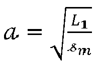
- determining a scaling factor a according to

- calculating a mixing matrix G according to G = a U Ŝ VT .
- obtaining a first mixing matrix Ĝ from virtual source directions
- 6. Method according to one of the EEEs 1-5, wherein the input signal is optimized for L1 regular loudspeaker positions and the rendering is optimized for L2 arbitrary loudspeaker positions, wherein at least one of the arbitrary loudspeaker positions is different from the regular loudspeaker positions.
- 7. A computer-implemented method (s710) for generating an energy preserving mixing matrix G for mixing input channel-based audio signals for L1 audio channels to L2 loudspeaker channels, the method comprising steps executed by the computer of
- obtaining (s711) a first mixing matrix Ĝ from virtual source directions


- performing (s712) a singular value decomposition on the first mixing matrix Ĝ according to Ĝ = U S VT , wherein


- processing (s713) the singularity matrix S , wherein a quantized singularity matrix Ŝ is obtained with diagonal elements that are above a threshold set to one and diagonal elements that are below a threshold set to zero;
- determining (s714) a number of diagonal elements that are set to one in the quantized singularity matrix Ŝ;

- determining (s715) a scaling factor a according to


calculating (s716) a mixing matrix G according to G = a U Ŝ VT .
- obtaining (s711) a first mixing matrix Ĝ from virtual source directions
- 8. An apparatus (70) for rendering L1 channel-based input audio signals (w11) to L2 loudspeaker channels, where L1 is different from L2, the apparatus comprising at least one of each of
- a determining unit (75) for determining a mix type of the L1 input audio signals, wherein possible mix types include at least one of spherical, cylindrical and rectangular;
- a first delay and gain compensation unit (71) for performing a first delay and gain compensation on the L1 input audio signals according to the determined mix type, wherein a delay and gain compensated input audio signal (q71) with L1 channels and with a defined mix type (q72) is obtained;
- a mixer unit (72) for mixing the delay and gain compensated input audio signal (q71) for L2 audio channels, wherein a remixed audio signal (q72) for L2 audio channels is obtained;
- a clipping unit (73) for clipping the remixed audio signal (q72), wherein a clipped remixed audio signal (q73) for L2 audio channels is obtained; and
- a second delay and gain compensation unit (74) for performing a second delay and gain compensation on the clipped remixed audio signal (q73) for L2 audio channels, wherein L2 loudspeaker channels (w22) are obtained.
- 9. Apparatus according to
EEE 8, further comprising an equalization filter (722) for filtering the delay and gain compensated input audio signal (q71) with L1 channels, wherein a filtered delay and gain compensated input audio signal (q722) is obtained. - 10. Apparatus according to
EEE 9, wherein the equalization filter (722) comprises different types of filters that are used for the channels, wherein at least one channel uses a high-pass filter and at least one channel uses a low-pass filter. - 11. Apparatus according to one of the EEEs 8-10, wherein the defined mix type is spherical.
- 12. Apparatus according to one of the EEEs 8-11, wherein the mixer unit (724) mixes the delay and gain compensated input audio signal (q71) for L2 audio channels uses an energy preserving mixing matrix G that is obtained by a mixing matrix generation unit that comprises one or more processors for implementing
- a first calculating module for obtaining a first mixing matrix Ĝ from virtual source directions


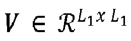
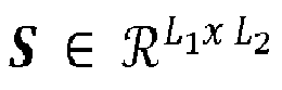
- a singular value decomposition module for performing a singular value decomposition on the first mixing matrix Ĝ according to Ĝ = U S VT wherein U ∈

- a processing module for processing the singularity matrix S, wherein a quantized singularity matrix Ŝ is obtained with diagonal elements that are above a threshold set to one and diagonal elements that are below a threshold set to zero;
- a counting module for determining a number of diagonal elements that are set to one in the quantized singularity matrix Ŝ;

- a second calculating module for determining a scaling factor a according to

- a third calculating module for calculating a mixing matrix G according to

- a first calculating module for obtaining a first mixing matrix Ĝ from virtual source directions
- 13. Apparatus according to one of the EEEs 8-12, wherein the input signal is optimized for L1 regular loudspeaker positions and the rendering is optimized for L2 arbitrary loudspeaker positions, wherein at least one of the arbitrary loudspeaker positions is different from the regular loudspeaker positions.
- 14. Apparatus for obtaining an energy preserving mixing matrix G for mixing input channel-based audio signals for L1 audio channels to L2 loudspeaker channels, comprising at least one processing element for implementing
- a first calculation module for obtaining a first mixing matrix Ĝ from virtual source directions


- a singular value decomposition module for performing a singular value decomposition on the first mixing matrix Ĝ according to Ĝ = U S VT , wherein U ∈


- a processing module processing the singularity matrix S, wherein a quantized singularity matrix Ŝ is obtained with diagonal elements that are above a threshold set to one and diagonal elements that are below a threshold set to zero;
- a counting module for determining a number of diagonal elements that are set to one in the quantized singularity matrix Ŝ;

- a second calculation module for determining a scaling factor a according to

- a third calculation module for calculating a mixing matrix G according to

- a first calculation module for obtaining a first mixing matrix Ĝ from virtual source directions
- 15. A computer readable storage medium having stored thereon instructions that when executed on a computer cause the computer to perform a method according to one of the EEEs 1-6.
Claims (7)
- A method for loudspeaker rendering, the method comprising:determining a mix type for channel-based input audio signals, wherein the mix type specifies a geometry for reproducing the input audio signals;performing a first delay and gain compensation on the input audio signals based on the determined mix type to obtain a delay and gain compensated input audio signal with a defined mix type;determining a remixed audio signal for output audio channels based on applying an energy preserving mixing matrix to the delay and gain compensated input audio signal for L2 audio channels, wherein the remixed audio signal for output audio channels is further based on a second delay and gain compensation;wherein the energy preserving mixing matrix has matrix elements that are energy scaled based on a threshold and a scaling factor.
- The method of claim 1, wherein the defined mix type is spherical.
- The method of claim 1 or claim 2, wherein the input signal is optimized for L1 regular loudspeaker positions and the rendering is optimized for L2 arbitrary loudspeaker positions, wherein at least one of the L2 arbitrary loudspeaker positions is different from the L1 regular loudspeaker positions.
- An apparatus for loudspeaker rendering, the apparatus comprising at least one processor comprising at least one of each of:a determining unit for determining a mix type for channel-based input audio signals, wherein the mix type specifies a geometry for reproducing the input audio signals;a first delay and compensation unit for performing a first delay and gain compensation on the input audio signals based on the determined mix type to obtain a delay and gain compensated input audio signal with a defined mix type;a remixing unit for determining a remixed audio signal for output audio channels based on applying an energy preserving mixing matrix to the delay and gain compensated input audio signal for L2 audio channels, wherein the remixed audio signal for output audio channels is further based on a second delay and gain compensation, and,wherein the energy preserving mixing matrix has matrix elements that are energy scaled based on a threshold and a scaling factor.
- The apparatus of claim 4, wherein the defined mix type is spherical.
- The apparatus of claim 4 or claim 5, wherein the input signal is optimized for L1 regular loudspeaker positions and the rendering is optimized for L2 arbitrary loudspeaker positions, wherein at least one of the L2 arbitrary loudspeaker positions is different from the L1 regular loudspeaker positions.
- A non-transitory computer readable storage medium having stored thereon instructions that when executed on a computer cause the computer to perform a method of any one of claims 1-3.
Applications Claiming Priority (3)
| Application Number | Priority Date | Filing Date | Title |
|---|---|---|---|
| EP13306042 | 2013-07-19 | ||
| PCT/EP2014/065517 WO2015007889A2 (en) | 2013-07-19 | 2014-07-18 | Method for rendering multi-channel audio signals for l1 channels to a different number l2 of loudspeaker channels and apparatus for rendering multi-channel audio signals for l1 channels to a different number l2 of loudspeaker channels |
| EP14747865.5A EP3022950B1 (en) | 2013-07-19 | 2014-07-18 | Method for rendering multi-channel audio signals for l1 channels to a different number l2 of loudspeaker channels and apparatus for rendering multi-channel audio signals for l1 channels to a different number l2 of loudspeaker channels |
Related Parent Applications (2)
| Application Number | Title | Priority Date | Filing Date |
|---|---|---|---|
| EP14747865.5A Division EP3022950B1 (en) | 2013-07-19 | 2014-07-18 | Method for rendering multi-channel audio signals for l1 channels to a different number l2 of loudspeaker channels and apparatus for rendering multi-channel audio signals for l1 channels to a different number l2 of loudspeaker channels |
| EP14747865.5A Division-Into EP3022950B1 (en) | 2013-07-19 | 2014-07-18 | Method for rendering multi-channel audio signals for l1 channels to a different number l2 of loudspeaker channels and apparatus for rendering multi-channel audio signals for l1 channels to a different number l2 of loudspeaker channels |
Publications (2)
| Publication Number | Publication Date |
|---|---|
| EP3531721A1 true EP3531721A1 (en) | 2019-08-28 |
| EP3531721B1 EP3531721B1 (en) | 2020-10-21 |
Family
ID=48949099
Family Applications (2)
| Application Number | Title | Priority Date | Filing Date |
|---|---|---|---|
| EP18199889.9A Active EP3531721B1 (en) | 2013-07-19 | 2014-07-18 | Method for rendering multi-channel audio signals for l1 channels to a different number l2 of loudspeaker channels and apparatus for rendering multi-channel audio signals for l1 channels to a different number l2 of loudspeaker channels |
| EP14747865.5A Active EP3022950B1 (en) | 2013-07-19 | 2014-07-18 | Method for rendering multi-channel audio signals for l1 channels to a different number l2 of loudspeaker channels and apparatus for rendering multi-channel audio signals for l1 channels to a different number l2 of loudspeaker channels |
Family Applications After (1)
| Application Number | Title | Priority Date | Filing Date |
|---|---|---|---|
| EP14747865.5A Active EP3022950B1 (en) | 2013-07-19 | 2014-07-18 | Method for rendering multi-channel audio signals for l1 channels to a different number l2 of loudspeaker channels and apparatus for rendering multi-channel audio signals for l1 channels to a different number l2 of loudspeaker channels |
Country Status (4)
| Country | Link |
|---|---|
| US (3) | US9628933B2 (en) |
| EP (2) | EP3531721B1 (en) |
| TW (2) | TWI673707B (en) |
| WO (1) | WO2015007889A2 (en) |
Families Citing this family (18)
| Publication number | Priority date | Publication date | Assignee | Title |
|---|---|---|---|---|
| US9769586B2 (en) | 2013-05-29 | 2017-09-19 | Qualcomm Incorporated | Performing order reduction with respect to higher order ambisonic coefficients |
| US9466305B2 (en) | 2013-05-29 | 2016-10-11 | Qualcomm Incorporated | Performing positional analysis to code spherical harmonic coefficients |
| US9502045B2 (en) | 2014-01-30 | 2016-11-22 | Qualcomm Incorporated | Coding independent frames of ambient higher-order ambisonic coefficients |
| US9922656B2 (en) | 2014-01-30 | 2018-03-20 | Qualcomm Incorporated | Transitioning of ambient higher-order ambisonic coefficients |
| RU2658888C2 (en) | 2014-03-24 | 2018-06-25 | Долби Интернэшнл Аб | Method and device of the dynamic range compression application to the higher order ambiophony signal |
| US10770087B2 (en) | 2014-05-16 | 2020-09-08 | Qualcomm Incorporated | Selecting codebooks for coding vectors decomposed from higher-order ambisonic audio signals |
| US9852737B2 (en) | 2014-05-16 | 2017-12-26 | Qualcomm Incorporated | Coding vectors decomposed from higher-order ambisonics audio signals |
| US9620137B2 (en) | 2014-05-16 | 2017-04-11 | Qualcomm Incorporated | Determining between scalar and vector quantization in higher order ambisonic coefficients |
| US9747910B2 (en) | 2014-09-26 | 2017-08-29 | Qualcomm Incorporated | Switching between predictive and non-predictive quantization techniques in a higher order ambisonics (HOA) framework |
| WO2016210174A1 (en) | 2015-06-25 | 2016-12-29 | Dolby Laboratories Licensing Corporation | Audio panning transformation system and method |
| US10070094B2 (en) * | 2015-10-14 | 2018-09-04 | Qualcomm Incorporated | Screen related adaptation of higher order ambisonic (HOA) content |
| JP6821795B2 (en) * | 2016-09-14 | 2021-01-27 | マジック リープ, インコーポレイテッドMagic Leap,Inc. | Virtual reality, augmented reality, and mixed reality systems with spatialized audio |
| US10405126B2 (en) * | 2017-06-30 | 2019-09-03 | Qualcomm Incorporated | Mixed-order ambisonics (MOA) audio data for computer-mediated reality systems |
| US10499153B1 (en) * | 2017-11-29 | 2019-12-03 | Boomcloud 360, Inc. | Enhanced virtual stereo reproduction for unmatched transaural loudspeaker systems |
| US10524078B2 (en) | 2017-11-29 | 2019-12-31 | Boomcloud 360, Inc. | Crosstalk cancellation b-chain |
| WO2021098957A1 (en) * | 2019-11-20 | 2021-05-27 | Fraunhofer-Gesellschaft zur Förderung der angewandten Forschung e.V. | Audio object renderer, methods for determining loudspeaker gains and computer program using panned object loudspeaker gains and spread object loudspeaker gains |
| US11743670B2 (en) | 2020-12-18 | 2023-08-29 | Qualcomm Incorporated | Correlation-based rendering with multiple distributed streams accounting for an occlusion for six degree of freedom applications |
| CN117651238B (en) * | 2024-01-30 | 2024-05-31 | 科大讯飞(苏州)科技有限公司 | Audio playing method, audio compensation coefficient determining method and automobile |
Citations (2)
| Publication number | Priority date | Publication date | Assignee | Title |
|---|---|---|---|---|
| US5594800A (en) * | 1991-02-15 | 1997-01-14 | Trifield Productions Limited | Sound reproduction system having a matrix converter |
| US20120082319A1 (en) * | 2010-09-08 | 2012-04-05 | Jean-Marc Jot | Spatial audio encoding and reproduction of diffuse sound |
Family Cites Families (4)
| Publication number | Priority date | Publication date | Assignee | Title |
|---|---|---|---|---|
| CN100481722C (en) * | 2002-06-05 | 2009-04-22 | 索尼克焦点公司 | System and method for enhancing delivered sound in acoustical virtual reality |
| JP4685106B2 (en) * | 2005-07-29 | 2011-05-18 | ハーマン インターナショナル インダストリーズ インコーポレイテッド | Audio adjustment system |
| JP2012022731A (en) * | 2010-07-12 | 2012-02-02 | Hitachi Ltd | Magnetic head slider and magnetic disk device using the same |
| RU2676415C1 (en) * | 2014-04-11 | 2018-12-28 | Самсунг Электроникс Ко., Лтд. | Method and device for rendering of sound signal and computer readable information media |
-
2014
- 2014-07-16 TW TW107116311A patent/TWI673707B/en active
- 2014-07-16 TW TW103124331A patent/TWI631553B/en active
- 2014-07-18 US US14/906,255 patent/US9628933B2/en active Active
- 2014-07-18 EP EP18199889.9A patent/EP3531721B1/en active Active
- 2014-07-18 EP EP14747865.5A patent/EP3022950B1/en active Active
- 2014-07-18 WO PCT/EP2014/065517 patent/WO2015007889A2/en not_active Ceased
-
2017
- 2017-03-13 US US15/457,718 patent/US10091601B2/en active Active
-
2018
- 2018-09-06 US US16/123,980 patent/US20190007779A1/en not_active Abandoned
Patent Citations (2)
| Publication number | Priority date | Publication date | Assignee | Title |
|---|---|---|---|---|
| US5594800A (en) * | 1991-02-15 | 1997-01-14 | Trifield Productions Limited | Sound reproduction system having a matrix converter |
| US20120082319A1 (en) * | 2010-09-08 | 2012-04-05 | Jean-Marc Jot | Spatial audio encoding and reproduction of diffuse sound |
Non-Patent Citations (12)
| Title |
|---|
| "Algorithms to measure audio programme loudness and true-peak audio level", TU-R RECOMMENDATION BS. 1770-2, 2011 |
| "Loudness Normalization and Permitted Maximum Level of Audio Signals", EBU TECHNICAL RECOMMENDATION R128, 2010, Retrieved from the Internet <URL:http://tech.ebu.ch/docs/r/r128.pdf> |
| "Techniques for Establishing and Maintaining Audio Loudness for Digital Television", ADVANCED TELEVISION SYSTEMS COMMITTEE, 25 July 2011 (2011-07-25) |
| FAZI, F.; YAMADA, T; KAMDAR, S.; NELSON P.A.; OTTO, P.: "Surround Sound Panning Technique Based on a Virtual Microphone Array", AES CONVENTION, vol. 128, May 2010 (2010-05-01) |
| HAMASAKI, K.; NISHIGUCHI,T.; OKUMURA, R.; NAKAYAMA, Y.; ANDO, A.: "A 22.2 multichannel sound system for ultrahigh-definition TV (UHDTV", SMPTE MOTION IMAGING J., April 2008 (2008-04-01), pages 40 - 49, XP055095219, DOI: doi:10.5594/J15119 |
| ITU-R BS 775-1, 1994 |
| JORG FLIEGE; ULRIKE MAIER: "Technical report, Fachbereich Mathematik", 1999, UNIVERSITAT DORTMUND, article "A two-stage approach for computing cubature formulae for the sphere" |
| O. KIRKEBY; P. A. NELSON: "Reproduction of plane wave sound fields", J. ACOUST. SOC. AM., vol. 94, no. 5, 1993, pages 2992 - 3000, XP000413485, DOI: doi:10.1121/1.407330 |
| POLETTI, M.: "Robust two-dimensional surround sound reproduction for non-uniform loudspeaker layouts", J. AUDIO ENG. SOC., vol. 55, no. 7/8, July 2007 (2007-07-01), pages 598 - 610 |
| PULKKI, V.: "Virtual Sound Source Positioning Using Vector Base Amplitude Panning", J. AUDIO ENG. SOC., vol. 45, June 1997 (1997-06-01), pages 456 - 466, XP002719359 |
| SHIN, M.; FAZI, F.; SEO, J.; NELSON, P. A.: "Efficient 3-D Sound Field Reproduction", AES CONVENTION, vol. 1 30, May 2011 (2011-05-01) |
| ZOTTER F ET AL: "Energy-Preserving Ambisonic Decoding", ACTA ACUSTICA UNITED WITH ACUSTICA, EUROPEAN ACOUSTICS ASSOCIATION, STUTTGART : HIRZEL, vol. 98, no. 1, 1 January 2012 (2012-01-01), pages 37 - 47, XP009180661, ISSN: 1436-7947, DOI: 10.3813/AAA.918490 * |
Also Published As
| Publication number | Publication date |
|---|---|
| TW201514455A (en) | 2015-04-16 |
| EP3022950A2 (en) | 2016-05-25 |
| WO2015007889A3 (en) | 2015-07-16 |
| WO2015007889A2 (en) | 2015-01-22 |
| US20190007779A1 (en) | 2019-01-03 |
| TW201832224A (en) | 2018-09-01 |
| US20170251322A1 (en) | 2017-08-31 |
| US20160174008A1 (en) | 2016-06-16 |
| US9628933B2 (en) | 2017-04-18 |
| EP3531721B1 (en) | 2020-10-21 |
| EP3022950B1 (en) | 2018-11-21 |
| TWI673707B (en) | 2019-10-01 |
| TWI631553B (en) | 2018-08-01 |
| US10091601B2 (en) | 2018-10-02 |
Similar Documents
| Publication | Publication Date | Title |
|---|---|---|
| EP3022950B1 (en) | Method for rendering multi-channel audio signals for l1 channels to a different number l2 of loudspeaker channels and apparatus for rendering multi-channel audio signals for l1 channels to a different number l2 of loudspeaker channels | |
| US11832080B2 (en) | Spatial audio parameters and associated spatial audio playback | |
| US11785408B2 (en) | Determination of targeted spatial audio parameters and associated spatial audio playback | |
| RU2640647C2 (en) | Device and method of transforming first and second input channels, at least, in one output channel | |
| US20180367934A1 (en) | Method and device for rendering an audio soundfield representation | |
| US9729991B2 (en) | Apparatus and method for generating an output signal employing a decomposer | |
| CN108174341B (en) | Method and apparatus for measuring higher order ambisonics loudness level | |
| US20210250717A1 (en) | Spatial audio Capture, Transmission and Reproduction | |
| HK40007289A (en) | Method for rendering multi-channel audio signals for l1 channels to a different number l2 of loudspeaker channels and apparatus for rendering multi-channel audio signals for l1 channels to a different number l2 of loudspeaker channels | |
| HK40007289B (en) | Method for rendering multi-channel audio signals for l1 channels to a different number l2 of loudspeaker channels and apparatus for rendering multi-channel audio signals for l1 channels to a different number l2 of loudspeaker channels | |
| US20240274137A1 (en) | Parametric spatial audio rendering | |
| AU2015255287B2 (en) | Apparatus and method for generating an output signal employing a decomposer | |
| HK1256573B (en) | Method for measuring hoa loudness level and device for measuring hoa loudness level | |
| HK1252865A1 (en) | Generating binaural audio in response to multi-channel audio using at least one feedback delay network |
Legal Events
| Date | Code | Title | Description |
|---|---|---|---|
| PUAI | Public reference made under article 153(3) epc to a published international application that has entered the european phase |
Free format text: ORIGINAL CODE: 0009012 |
|
| STAA | Information on the status of an ep patent application or granted ep patent |
Free format text: STATUS: THE APPLICATION HAS BEEN PUBLISHED |
|
| AC | Divisional application: reference to earlier application |
Ref document number: 3022950 Country of ref document: EP Kind code of ref document: P |
|
| AK | Designated contracting states |
Kind code of ref document: A1 Designated state(s): AL AT BE BG CH CY CZ DE DK EE ES FI FR GB GR HR HU IE IS IT LI LT LU LV MC MK MT NL NO PL PT RO RS SE SI SK SM TR |
|
| STAA | Information on the status of an ep patent application or granted ep patent |
Free format text: STATUS: REQUEST FOR EXAMINATION WAS MADE |
|
| 17P | Request for examination filed |
Effective date: 20200228 |
|
| RBV | Designated contracting states (corrected) |
Designated state(s): AL AT BE BG CH CY CZ DE DK EE ES FI FR GB GR HR HU IE IS IT LI LT LU LV MC MK MT NL NO PL PT RO RS SE SI SK SM TR |
|
| REG | Reference to a national code |
Ref country code: HK Ref legal event code: DE Ref document number: 40007289 Country of ref document: HK |
|
| GRAP | Despatch of communication of intention to grant a patent |
Free format text: ORIGINAL CODE: EPIDOSNIGR1 |
|
| STAA | Information on the status of an ep patent application or granted ep patent |
Free format text: STATUS: GRANT OF PATENT IS INTENDED |
|
| INTG | Intention to grant announced |
Effective date: 20200617 |
|
| GRAS | Grant fee paid |
Free format text: ORIGINAL CODE: EPIDOSNIGR3 |
|
| GRAA | (expected) grant |
Free format text: ORIGINAL CODE: 0009210 |
|
| STAA | Information on the status of an ep patent application or granted ep patent |
Free format text: STATUS: THE PATENT HAS BEEN GRANTED |
|
| AC | Divisional application: reference to earlier application |
Ref document number: 3022950 Country of ref document: EP Kind code of ref document: P |
|
| AK | Designated contracting states |
Kind code of ref document: B1 Designated state(s): AL AT BE BG CH CY CZ DE DK EE ES FI FR GB GR HR HU IE IS IT LI LT LU LV MC MK MT NL NO PL PT RO RS SE SI SK SM TR |
|
| REG | Reference to a national code |
Ref country code: GB Ref legal event code: FG4D |
|
| REG | Reference to a national code |
Ref country code: CH Ref legal event code: EP |
|
| REG | Reference to a national code |
Ref country code: DE Ref legal event code: R096 Ref document number: 602014071604 Country of ref document: DE |
|
| REG | Reference to a national code |
Ref country code: IE Ref legal event code: FG4D |
|
| REG | Reference to a national code |
Ref country code: AT Ref legal event code: REF Ref document number: 1327085 Country of ref document: AT Kind code of ref document: T Effective date: 20201115 |
|
| REG | Reference to a national code |
Ref country code: AT Ref legal event code: MK05 Ref document number: 1327085 Country of ref document: AT Kind code of ref document: T Effective date: 20201021 |
|
| REG | Reference to a national code |
Ref country code: NL Ref legal event code: MP Effective date: 20201021 |
|
| PG25 | Lapsed in a contracting state [announced via postgrant information from national office to epo] |
Ref country code: FI Free format text: LAPSE BECAUSE OF FAILURE TO SUBMIT A TRANSLATION OF THE DESCRIPTION OR TO PAY THE FEE WITHIN THE PRESCRIBED TIME-LIMIT Effective date: 20201021 Ref country code: PT Free format text: LAPSE BECAUSE OF FAILURE TO SUBMIT A TRANSLATION OF THE DESCRIPTION OR TO PAY THE FEE WITHIN THE PRESCRIBED TIME-LIMIT Effective date: 20210222 Ref country code: RS Free format text: LAPSE BECAUSE OF FAILURE TO SUBMIT A TRANSLATION OF THE DESCRIPTION OR TO PAY THE FEE WITHIN THE PRESCRIBED TIME-LIMIT Effective date: 20201021 Ref country code: NO Free format text: LAPSE BECAUSE OF FAILURE TO SUBMIT A TRANSLATION OF THE DESCRIPTION OR TO PAY THE FEE WITHIN THE PRESCRIBED TIME-LIMIT Effective date: 20210121 Ref country code: GR Free format text: LAPSE BECAUSE OF FAILURE TO SUBMIT A TRANSLATION OF THE DESCRIPTION OR TO PAY THE FEE WITHIN THE PRESCRIBED TIME-LIMIT Effective date: 20210122 |
|
| REG | Reference to a national code |
Ref country code: LT Ref legal event code: MG4D |
|
| PG25 | Lapsed in a contracting state [announced via postgrant information from national office to epo] |
Ref country code: ES Free format text: LAPSE BECAUSE OF FAILURE TO SUBMIT A TRANSLATION OF THE DESCRIPTION OR TO PAY THE FEE WITHIN THE PRESCRIBED TIME-LIMIT Effective date: 20201021 Ref country code: AT Free format text: LAPSE BECAUSE OF FAILURE TO SUBMIT A TRANSLATION OF THE DESCRIPTION OR TO PAY THE FEE WITHIN THE PRESCRIBED TIME-LIMIT Effective date: 20201021 Ref country code: BG Free format text: LAPSE BECAUSE OF FAILURE TO SUBMIT A TRANSLATION OF THE DESCRIPTION OR TO PAY THE FEE WITHIN THE PRESCRIBED TIME-LIMIT Effective date: 20210121 Ref country code: SE Free format text: LAPSE BECAUSE OF FAILURE TO SUBMIT A TRANSLATION OF THE DESCRIPTION OR TO PAY THE FEE WITHIN THE PRESCRIBED TIME-LIMIT Effective date: 20201021 Ref country code: IS Free format text: LAPSE BECAUSE OF FAILURE TO SUBMIT A TRANSLATION OF THE DESCRIPTION OR TO PAY THE FEE WITHIN THE PRESCRIBED TIME-LIMIT Effective date: 20210221 Ref country code: LV Free format text: LAPSE BECAUSE OF FAILURE TO SUBMIT A TRANSLATION OF THE DESCRIPTION OR TO PAY THE FEE WITHIN THE PRESCRIBED TIME-LIMIT Effective date: 20201021 Ref country code: PL Free format text: LAPSE BECAUSE OF FAILURE TO SUBMIT A TRANSLATION OF THE DESCRIPTION OR TO PAY THE FEE WITHIN THE PRESCRIBED TIME-LIMIT Effective date: 20201021 |
|
| PG25 | Lapsed in a contracting state [announced via postgrant information from national office to epo] |
Ref country code: NL Free format text: LAPSE BECAUSE OF FAILURE TO SUBMIT A TRANSLATION OF THE DESCRIPTION OR TO PAY THE FEE WITHIN THE PRESCRIBED TIME-LIMIT Effective date: 20201021 Ref country code: HR Free format text: LAPSE BECAUSE OF FAILURE TO SUBMIT A TRANSLATION OF THE DESCRIPTION OR TO PAY THE FEE WITHIN THE PRESCRIBED TIME-LIMIT Effective date: 20201021 |
|
| REG | Reference to a national code |
Ref country code: DE Ref legal event code: R097 Ref document number: 602014071604 Country of ref document: DE |
|
| PG25 | Lapsed in a contracting state [announced via postgrant information from national office to epo] |
Ref country code: SK Free format text: LAPSE BECAUSE OF FAILURE TO SUBMIT A TRANSLATION OF THE DESCRIPTION OR TO PAY THE FEE WITHIN THE PRESCRIBED TIME-LIMIT Effective date: 20201021 Ref country code: RO Free format text: LAPSE BECAUSE OF FAILURE TO SUBMIT A TRANSLATION OF THE DESCRIPTION OR TO PAY THE FEE WITHIN THE PRESCRIBED TIME-LIMIT Effective date: 20201021 Ref country code: LT Free format text: LAPSE BECAUSE OF FAILURE TO SUBMIT A TRANSLATION OF THE DESCRIPTION OR TO PAY THE FEE WITHIN THE PRESCRIBED TIME-LIMIT Effective date: 20201021 Ref country code: CZ Free format text: LAPSE BECAUSE OF FAILURE TO SUBMIT A TRANSLATION OF THE DESCRIPTION OR TO PAY THE FEE WITHIN THE PRESCRIBED TIME-LIMIT Effective date: 20201021 Ref country code: EE Free format text: LAPSE BECAUSE OF FAILURE TO SUBMIT A TRANSLATION OF THE DESCRIPTION OR TO PAY THE FEE WITHIN THE PRESCRIBED TIME-LIMIT Effective date: 20201021 Ref country code: SM Free format text: LAPSE BECAUSE OF FAILURE TO SUBMIT A TRANSLATION OF THE DESCRIPTION OR TO PAY THE FEE WITHIN THE PRESCRIBED TIME-LIMIT Effective date: 20201021 |
|
| PLBE | No opposition filed within time limit |
Free format text: ORIGINAL CODE: 0009261 |
|
| STAA | Information on the status of an ep patent application or granted ep patent |
Free format text: STATUS: NO OPPOSITION FILED WITHIN TIME LIMIT |
|
| PG25 | Lapsed in a contracting state [announced via postgrant information from national office to epo] |
Ref country code: DK Free format text: LAPSE BECAUSE OF FAILURE TO SUBMIT A TRANSLATION OF THE DESCRIPTION OR TO PAY THE FEE WITHIN THE PRESCRIBED TIME-LIMIT Effective date: 20201021 |
|
| 26N | No opposition filed |
Effective date: 20210722 |
|
| PG25 | Lapsed in a contracting state [announced via postgrant information from national office to epo] |
Ref country code: AL Free format text: LAPSE BECAUSE OF FAILURE TO SUBMIT A TRANSLATION OF THE DESCRIPTION OR TO PAY THE FEE WITHIN THE PRESCRIBED TIME-LIMIT Effective date: 20201021 Ref country code: IT Free format text: LAPSE BECAUSE OF FAILURE TO SUBMIT A TRANSLATION OF THE DESCRIPTION OR TO PAY THE FEE WITHIN THE PRESCRIBED TIME-LIMIT Effective date: 20201021 |
|
| PG25 | Lapsed in a contracting state [announced via postgrant information from national office to epo] |
Ref country code: SI Free format text: LAPSE BECAUSE OF FAILURE TO SUBMIT A TRANSLATION OF THE DESCRIPTION OR TO PAY THE FEE WITHIN THE PRESCRIBED TIME-LIMIT Effective date: 20201021 |
|
| REG | Reference to a national code |
Ref country code: CH Ref legal event code: PL |
|
| PG25 | Lapsed in a contracting state [announced via postgrant information from national office to epo] |
Ref country code: MC Free format text: LAPSE BECAUSE OF FAILURE TO SUBMIT A TRANSLATION OF THE DESCRIPTION OR TO PAY THE FEE WITHIN THE PRESCRIBED TIME-LIMIT Effective date: 20201021 |
|
| REG | Reference to a national code |
Ref country code: BE Ref legal event code: MM Effective date: 20210731 |
|
| PG25 | Lapsed in a contracting state [announced via postgrant information from national office to epo] |
Ref country code: LI Free format text: LAPSE BECAUSE OF NON-PAYMENT OF DUE FEES Effective date: 20210731 Ref country code: CH Free format text: LAPSE BECAUSE OF NON-PAYMENT OF DUE FEES Effective date: 20210731 |
|
| PG25 | Lapsed in a contracting state [announced via postgrant information from national office to epo] |
Ref country code: IS Free format text: LAPSE BECAUSE OF FAILURE TO SUBMIT A TRANSLATION OF THE DESCRIPTION OR TO PAY THE FEE WITHIN THE PRESCRIBED TIME-LIMIT Effective date: 20210221 Ref country code: LU Free format text: LAPSE BECAUSE OF NON-PAYMENT OF DUE FEES Effective date: 20210718 |
|
| PG25 | Lapsed in a contracting state [announced via postgrant information from national office to epo] |
Ref country code: IE Free format text: LAPSE BECAUSE OF NON-PAYMENT OF DUE FEES Effective date: 20210718 Ref country code: BE Free format text: LAPSE BECAUSE OF NON-PAYMENT OF DUE FEES Effective date: 20210731 |
|
| REG | Reference to a national code |
Ref country code: DE Ref legal event code: R081 Ref document number: 602014071604 Country of ref document: DE Owner name: DOLBY INTERNATIONAL AB, IE Free format text: FORMER OWNER: DOLBY INTERNATIONAL AB, AMSTERDAM, NL Ref country code: DE Ref legal event code: R081 Ref document number: 602014071604 Country of ref document: DE Owner name: DOLBY INTERNATIONAL AB, NL Free format text: FORMER OWNER: DOLBY INTERNATIONAL AB, AMSTERDAM, NL |
|
| REG | Reference to a national code |
Ref country code: DE Ref legal event code: R081 Ref document number: 602014071604 Country of ref document: DE Owner name: DOLBY INTERNATIONAL AB, IE Free format text: FORMER OWNER: DOLBY INTERNATIONAL AB, DP AMSTERDAM, NL |
|
| P01 | Opt-out of the competence of the unified patent court (upc) registered |
Effective date: 20230512 |
|
| PG25 | Lapsed in a contracting state [announced via postgrant information from national office to epo] |
Ref country code: CY Free format text: LAPSE BECAUSE OF FAILURE TO SUBMIT A TRANSLATION OF THE DESCRIPTION OR TO PAY THE FEE WITHIN THE PRESCRIBED TIME-LIMIT Effective date: 20201021 |
|
| PG25 | Lapsed in a contracting state [announced via postgrant information from national office to epo] |
Ref country code: HU Free format text: LAPSE BECAUSE OF FAILURE TO SUBMIT A TRANSLATION OF THE DESCRIPTION OR TO PAY THE FEE WITHIN THE PRESCRIBED TIME-LIMIT; INVALID AB INITIO Effective date: 20140718 |
|
| PG25 | Lapsed in a contracting state [announced via postgrant information from national office to epo] |
Ref country code: MK Free format text: LAPSE BECAUSE OF FAILURE TO SUBMIT A TRANSLATION OF THE DESCRIPTION OR TO PAY THE FEE WITHIN THE PRESCRIBED TIME-LIMIT Effective date: 20201021 |
|
| PG25 | Lapsed in a contracting state [announced via postgrant information from national office to epo] |
Ref country code: TR Free format text: LAPSE BECAUSE OF FAILURE TO SUBMIT A TRANSLATION OF THE DESCRIPTION OR TO PAY THE FEE WITHIN THE PRESCRIBED TIME-LIMIT Effective date: 20201021 |
|
| PG25 | Lapsed in a contracting state [announced via postgrant information from national office to epo] |
Ref country code: MT Free format text: LAPSE BECAUSE OF FAILURE TO SUBMIT A TRANSLATION OF THE DESCRIPTION OR TO PAY THE FEE WITHIN THE PRESCRIBED TIME-LIMIT Effective date: 20201021 |
|
| PGFP | Annual fee paid to national office [announced via postgrant information from national office to epo] |
Ref country code: GB Payment date: 20250619 Year of fee payment: 12 |
|
| PGFP | Annual fee paid to national office [announced via postgrant information from national office to epo] |
Ref country code: FR Payment date: 20250619 Year of fee payment: 12 |
|
| PGFP | Annual fee paid to national office [announced via postgrant information from national office to epo] |
Ref country code: DE Payment date: 20250620 Year of fee payment: 12 |