EP3531690B1 - Dual-camera device and terminal device - Google Patents
Dual-camera device and terminal device Download PDFInfo
- Publication number
- EP3531690B1 EP3531690B1 EP17867360.4A EP17867360A EP3531690B1 EP 3531690 B1 EP3531690 B1 EP 3531690B1 EP 17867360 A EP17867360 A EP 17867360A EP 3531690 B1 EP3531690 B1 EP 3531690B1
- Authority
- EP
- European Patent Office
- Prior art keywords
- motor
- magnets
- dual
- hall effect
- effect sensor
- Prior art date
- Legal status (The legal status is an assumption and is not a legal conclusion. Google has not performed a legal analysis and makes no representation as to the accuracy of the status listed.)
- Active
Links
Images




Classifications
-
- H—ELECTRICITY
- H04—ELECTRIC COMMUNICATION TECHNIQUE
- H04N—PICTORIAL COMMUNICATION, e.g. TELEVISION
- H04N23/00—Cameras or camera modules comprising electronic image sensors; Control thereof
- H04N23/45—Cameras or camera modules comprising electronic image sensors; Control thereof for generating image signals from two or more image sensors being of different type or operating in different modes, e.g. with a CMOS sensor for moving images in combination with a charge-coupled device [CCD] for still images
-
- H—ELECTRICITY
- H04—ELECTRIC COMMUNICATION TECHNIQUE
- H04N—PICTORIAL COMMUNICATION, e.g. TELEVISION
- H04N23/00—Cameras or camera modules comprising electronic image sensors; Control thereof
- H04N23/60—Control of cameras or camera modules
- H04N23/68—Control of cameras or camera modules for stable pick-up of the scene, e.g. compensating for camera body vibrations
- H04N23/682—Vibration or motion blur correction
- H04N23/685—Vibration or motion blur correction performed by mechanical compensation
- H04N23/687—Vibration or motion blur correction performed by mechanical compensation by shifting the lens or sensor position
-
- G—PHYSICS
- G03—PHOTOGRAPHY; CINEMATOGRAPHY; ANALOGOUS TECHNIQUES USING WAVES OTHER THAN OPTICAL WAVES; ELECTROGRAPHY; HOLOGRAPHY
- G03B—APPARATUS OR ARRANGEMENTS FOR TAKING PHOTOGRAPHS OR FOR PROJECTING OR VIEWING THEM; APPARATUS OR ARRANGEMENTS EMPLOYING ANALOGOUS TECHNIQUES USING WAVES OTHER THAN OPTICAL WAVES; ACCESSORIES THEREFOR
- G03B13/00—Viewfinders; Focusing aids for cameras; Means for focusing for cameras; Autofocus systems for cameras
- G03B13/32—Means for focusing
- G03B13/34—Power focusing
- G03B13/36—Autofocus systems
-
- H—ELECTRICITY
- H04—ELECTRIC COMMUNICATION TECHNIQUE
- H04M—TELEPHONIC COMMUNICATION
- H04M1/00—Substation equipment, e.g. for use by subscribers
- H04M1/02—Constructional features of telephone sets
- H04M1/0202—Portable telephone sets, e.g. cordless phones, mobile phones or bar type handsets
- H04M1/026—Details of the structure or mounting of specific components
- H04M1/0264—Details of the structure or mounting of specific components for a camera module assembly
-
- H—ELECTRICITY
- H04—ELECTRIC COMMUNICATION TECHNIQUE
- H04N—PICTORIAL COMMUNICATION, e.g. TELEVISION
- H04N23/00—Cameras or camera modules comprising electronic image sensors; Control thereof
- H04N23/50—Constructional details
-
- H—ELECTRICITY
- H04—ELECTRIC COMMUNICATION TECHNIQUE
- H04N—PICTORIAL COMMUNICATION, e.g. TELEVISION
- H04N23/00—Cameras or camera modules comprising electronic image sensors; Control thereof
- H04N23/50—Constructional details
- H04N23/54—Mounting of pick-up tubes, electronic image sensors, deviation or focusing coils
-
- H—ELECTRICITY
- H04—ELECTRIC COMMUNICATION TECHNIQUE
- H04N—PICTORIAL COMMUNICATION, e.g. TELEVISION
- H04N23/00—Cameras or camera modules comprising electronic image sensors; Control thereof
- H04N23/90—Arrangement of cameras or camera modules, e.g. multiple cameras in TV studios or sports stadiums
-
- H—ELECTRICITY
- H04—ELECTRIC COMMUNICATION TECHNIQUE
- H04M—TELEPHONIC COMMUNICATION
- H04M2250/00—Details of telephonic subscriber devices
- H04M2250/12—Details of telephonic subscriber devices including a sensor for measuring a physical value, e.g. temperature or motion
-
- H—ELECTRICITY
- H04—ELECTRIC COMMUNICATION TECHNIQUE
- H04M—TELEPHONIC COMMUNICATION
- H04M2250/00—Details of telephonic subscriber devices
- H04M2250/52—Details of telephonic subscriber devices including functional features of a camera
Definitions
- This application relates to the communications field, and more specifically, to a dual-camera device and a terminal device.
- a dual camera usually includes two motors with a focus function.
- the motor measures and determines magnetic field intensity by disposing a Hall (Hall) effect sensor to determine a location of a lens, so as to implement focusing.
- a camera with a stabilization function is increasingly popularized, and the stabilization function is mainly implemented by using four magnets and four coils used to levitate and support the magnets in a power-on state.
- the magnetic interference caused by the motor with the stabilization function in the dual-camera mobile phone to the Hall effect sensor in the another motor is avoided by using software.
- this causes deterioration of photographing experience (for example, a focus time). Therefore, a solution capable of reducing magnetic interference caused by a motor with a stabilization function in a dual camera to a motor with an autofocus function is urgently expected, to improve user experience.
- WO 2016/156996 A1 describes dual-optical module autofocus (AF) or AF plus optical image stabilization (OIS) cameras with reduced footprint and reduced mutual magnetic interference.
- Some AF + OIS cameras may include a single AF actuation assembly that moves two lens barrels in unison.
- Some AF cameras or AF + OIS cameras may have two AF actuation sub-assemblies and associated magnets for independent AF operation of each lens barrel, the magnets shared in a manner that cancels magnetic influences of one AF actuation sub-assembly on the other AF actuation sub-assembly, thereby allowing the two lens barrels to be positioned in close proximity, saving parts and fabrication costs.
- CN105785547A describes another example of a dual camera having an automatic focusing mechanism.
- EP 3486718 A1 was cited during examination under Article 54(3) EPC for novelty only.
- EP 3486718 A1 describes a dual camera module comprising a first camera module and a second camera module, wherein: a first magnet unit of the first camera module includes a first magnet and a second magnet, both disposed opposite to each other on a side surface of a first housing; a second magnet unit of the second camera module includes a third to a sixth magnet arranged on four respective corners of a second housing; a third magnet unit is disposed on a side surface of the first housing facing the second housing; the third magnet unit is disposed between the first magnet and the second magnet; and the third magnet unit is smaller than the first magnet and is disposed on a virtual line connecting an optical axis of the first camera module and an optical axis of the second camera module.
- Embodiments of this application provide a dual-camera device and a terminal device, so that magnetic interference caused by a motor with a stabilization function to a Hall effect sensor in another motor can be reduced, and user experience can be improved.
- a dual-camera device including: a first camera, where the first camera includes a first motor, and the first motor includes at least one first Hall effect sensor; and a second camera, where the second camera includes a second motor, the second motor and the first motor are disposed in parallel, the second motor includes N second coils and N second magnets, the second coils are configured to levitate and support the second magnets during power-on, N is a positive integer, and N is a multiple of 4.
- a distance between a first disposition location of the first Hall effect sensor in the first motor and a second disposition location of the second magnets in the second motor is greater than or equal to a first preset distance.
- a housing material of the first motor or the second motor is a non-magnetic material.
- the first motor further includes M first coils and M first magnets, the first coils are configured to levitate and support the first magnets during power-on, M is a positive integer, and M is a multiple of 4;
- the second motor further includes at least one second Hall effect sensor, and a distance between a third disposition location of the second Hall effect sensor in the second motor and a fourth disposition location of the first magnets in the first motor is greater than or equal to a second preset distance.
- the distance between the Hall effect sensor in the first motor and the magnets in the second motor is greater than or equal to a first preset threshold, so that magnetic interference caused to the Hall effect sensor in the first motor by a magnetic field generated by the magnets in the second motor and the coils supporting the magnets in a power-on state is reduced, and user experience is improved.
- the first motor further includes K first magnets and an autofocus AF coil, the AF coil is in a ring shape, the K first magnets are placed opposite to each other along an outer wall of the ring shape, K is a positive integer, and K is a multiple of 2.
- the first motor may be an AF motor
- the second motor is a motor with a stabilization function. This reduces impact exerted on a focus function of the AF motor by the second motor, and reduces a focus time.
- locations of a Hall effect sensor and a magnet are laid out in one motor and locations of a Hall effect sensor and a magnet are laid out in another motor, to reduce magnetic interference between the two motors, and user experience is improved.
- the first motor further includes an AF coil, the AF coil is in a ring shape, and the M first magnets are placed pairwise opposite to each other around an outer wall of the ring shape.
- Locations of a Hall effect sensor and a magnet are laid out in an OIS motor and locations of a Hall effect sensor and a magnet are laid out in another motor, to reduce magnetic interference between the OIS motor and the motor with a stabilization function, so as to improve a focus function and a stabilization function of the OIS motor, and improve the stabilization function of the another motor.
- the second motor further includes an AF coil, the AF coil is in a ring shape, and the N second magnets are placed pairwise opposite to each other around an outer wall of the ring shape.
- Locations of a Hall effect sensor and a magnet are laid out in one OIS motor and locations of a Hall effect sensor and a magnet are laid out in another OIS motor, to reduce magnetic interference between the two OIS motors, and respectively improve focus functions and stabilization functions of the two OIS motors.
- the first magnets are bipolar magnets.
- Bipolar magnets may be used for the first motor to implement more desirable magnetic non-leakage, so that magnetic interference caused by the first motor to the Hall effect sensor in the second motor can be further reduced, and focus performance of the second motor can be improved.
- the second preset distance is a maximum value that can be reached by the distance between the third disposition location and the fourth disposition location.
- the second preset distance may be configured as a maximum distance between the disposition location of the second Hall effect sensor and the location of the first magnets. In this way, interference caused by the first motor to the second Hall effect sensor can be reduced as much as possible.
- the second preset distance is 5 mm.
- a second preset threshold may be set to 5 mm, so that interference between the second Hall effect sensor and the first magnets is effectively reduced.
- the first preset distance is a maximum value that can be reached by the distance between the first disposition location and the second disposition location.
- the first preset distance may be configured as a maximum distance between the disposition location of the first Hall effect sensor and the location of the second magnets. In this way, magnetic interference caused by the second motor to the first Hall effect sensor can be reduced as much as possible.
- the first preset distance is 5 mm.
- the first preset threshold may be set to 5 mm, so that interference caused by the second motor to the first Hall effect sensor is effectively reduced.
- the second magnets are bipolar magnets.
- Bipolar magnets may be used for the second motor to implement more desirable magnetic non-leakage, so that magnetic interference caused by the second motor to the Hall effect sensor in the first motor can be further reduced.
- a housing material of the first motor is SUS304 or SUS315.
- a housing material of the second motor is SUS304 or SUS315.
- a terminal device including the dual-camera device in any one of the first aspect and the possible implementations.
- the distance between the Hall effect sensor in the first motor and the magnets in the second motor is set to be greater than or equal to the first preset threshold in the embodiments of this application, so that magnetic interference caused to the Hall effect sensor in the first motor by the magnetic field generated by the magnets in the second motor and the coils supporting the magnets in a power-on state is reduced, and user experience is improved.
- a working principle of an autofocus (Autofocus, AF) motor is: A coil inside the motor is powered on to generate a magnetic field, a lens is moved based on magnetic force, and the AF motor measures and determines magnetic field intensity by using a Hall effect sensor to determine a location of the lens, moves the location of the entire lens by using a micro-distance, and controls a focal length, to implement clearness of an image.
- the AF motor mainly includes a voice coil motor, a stepper motor, liquid lens focus, a memory alloy motor, liquid crystal lens focus, and the like, and a most commonly used drive mechanism is the voice coil motor (Voice Coil Motor, VCM).
- FIG. 1 is a flowchart of an open loop and a closed loop.
- the open loop has a simple structure and low costs, works stably, and has a relatively good control effect when an input signal and input disturbance can be known in advance.
- an offset of a controlled value cannot be automatically corrected, and an element parameter change in a system and external unknown disturbance affect control precision.
- the closed loop has a capability of automatically correcting an offset of a controlled value by using feedback control, can correct an error caused by an element parameter change and external disturbance, and has high control precision.
- a closed-loop AF motor implements the foregoing function by using a Hall effect sensor, and the Hall effect sensor may measure and determine a Gaussian value in a magnetic field, so that a location of a lens can be further measured and determined.
- magnetic field intensity at locations of 0 and max of the lens is sensed by using the Hall effect sensor and is stored in a driver.
- Magnetic field intensity at a movement location can also be measured during motion of a focus lens set, and the intensity is returned to the driver.
- the driver obtains a positive or negative error based on the returned value, and then controls a moving direction and a moving speed of the focus lens set by using the positive or negative error. In this way, focus may be performed relatively precisely and quickly.
- An autofocus function of an OIS motor is implemented by an AF coil and two magnets opposite to each other.
- An OIS function is implemented by a lens levitation body (shown in FIG. 2 ) including four pairwise opposite magnets and four OIS coils.
- the OIS motor mainly includes a translation-type OIS focus motor and a shaft-moving-type focus motor. Principles of the two OIS motors are the same, to be specific, a lens is controlled to translate relative to an image sensor, so that an image offset caused by hand jitter is cancelled and compensated for.
- a type of the OIS motor is not limited in this embodiment of this application.
- the AF motor adjusts a focal length through movement in a vertical direction, and the OIS motor not only can move a lens in the vertical direction, but also can move a lens in a horizontal direction.
- a gyroscope built in a terminal device converts jitter information into an electrical signal and sends the electrical signal to an OIS control driver.
- the OIS control driver drives a motor to control motion of a levitation lens to compensate for impact generated by jitter.
- the Hall effect sensor feeds back location information of the lens to the OIS control driver, to form complete closed-loop control.
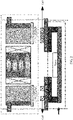
- FIG. 3 is a diagram of an internal structure of an autofocus (AF) motor.
- AF motors are further classified into an open-loop (open-loop) AF motor and a closed-loop (close loop) AF motor.
- the open-loop AF motor includes a cover 101 (cover), a yoke 102 (yoke), a top spring 103 (spring-top), a magnet 104 (magnet), a coil 105 (coil), a holder 106 (holder), a bottom spring 107 (spring-btm), a terminal 108 (terminal), and a base 109 (base).
- the closed-loop AF motor differs from the open-loop AF motor in that a bottom spring further includes a Hall magnet 110 (magnet Hall element), a Hall effect sensor 111 (Hall element), and a flexible circuit board 112 (FPC). It should be understood that the AF motor further includes a motor housing.
- a specific focus process includes the following steps:
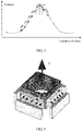
- FIG. 4 shows the focus principle. The figure describes the focus process. After two clearest areas are found by moving a lens, the lens is then slightly moved in the two areas to find a clear focus point. The motor moves the lens by using Ampere's force, and a fixed magnetic field and a coil through which a variant current runs are needed.
- a working principle of an autofocus motor is: In a permanent magnetic field, a stretching location of a spring plate is controlled by changing a value of a direct current in a coil inside the motor, to drive the lens to move up and down.
- the OIS motor has an autofocus function of the AF motor, and further has a stabilization function.
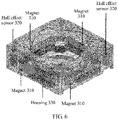
- the OIS motor usually includes four magnets 310 and Hall effect sensors 320 in an X-axis direction and in a Y-axis direction, and/or Hall effect sensors 320 and a housing 330 that are in a Z-axis direction.
- the housing usually uses an aluminum material.
- FIG. 6 is a structural diagram of an OIS motor. Four magnets are fastened to a yoke around a periphery. After power-on, magnetic force is generated by a magneto and a coil, to push a lens carrier to move. Two Hall effect sensors in a Z-axis direction, four magnets, and a housing are included in FIG. 6 .
- the Hall effect sensors in the X-axis direction and in the Y-axis direction are configured to detect magnetic field changes in the X direction and in the Y direction, and the Hall effect sensors in the Z-axis direction are configured to detect a magnetic field change in the Z-axis direction.
- One of two motors in a dual-camera device in the prior art has a stabilization function, and the other motor determines a location of a lens by measuring and determining magnetic field intensity by using a Hall effect sensor, to implement focus.
- the Hall effect sensors 320 and the magnets 104 are disposed at random, and a corresponding coil is disposed under each magnet. Therefore, when the coil is powered on, strong magnetic interference is caused to the Hall in the AF motor by magnetic field force generated by the magnet and the coil. Consequently, a focus speed and stabilization performance of photographing deteriorate.
- FIG. 7 shows the magnetic force generated by the coil and the magnet changes as a current in a powered-on coil in the OIS motor changes. To be specific, the magnetic force generated by the coil and the magnet increases as the power-on current increases from 0 mA to 100 mA.
- FIG. 8 is an elevational view of a motor structure of a dual-camera device according to an embodiment of this application.
- the dual-camera device includes: a first camera, where the first camera includes a first motor, and the first motor includes at least one first Hall Hall effect sensor; and a second camera, where the second camera includes a second motor, the second motor and the first motor are disposed in parallel, the second motor includes N second coils and N second magnets, the second coils are configured to levitate and support the second magnets during power-on, N is a positive integer, and N is a multiple of 4.
- a distance between a first disposition location of the first Hall effect sensor in the first motor and a second disposition location of the second magnets in the second motor is greater than or equal to a first preset distance.
- the first motor 410 includes the at least one first Hall effect sensor
- the second motor 420 includes the N second magnets and the N second coils (that is, OIS coils).
- N is greater than 4 and is a multiple of 4.
- a specific quantity may be determined based on a module size in the motor, a distance between the two cameras, and the like. This is not limited in this application.
- the first motor 410 includes one first Hall effect sensor 411 and the second motor 420 includes four second magnets 421 and four second coils (the coils are under the magnets, and this is not shown in FIG. 8 ) is used for description.
- the first Hall effect sensor 411 is disposed in the first motor 410
- the second magnets 421 are disposed in the second motor 420
- the distance between the first disposition location and the second disposition location is greater than or equal to the first preset distance.
- the sensors and the magnets may be laid out based on a magnetic field between the two motors, a sensitive area of the magnetic field is determined, and the disposition location of the Hall effect sensor in the first motor and the disposition location of the magnets in the second motor are laid out by using the magnetic sensitive area.
- the first preset distance may alternatively be determined based on factors such as sizes of internal space of the two motors (to be specific, the first preset distance is less than or equal to a maximum distance between internal components of the two motors) and measured data, or may be set at delivery or may be set by a user based on a requirement. This is not limited in this application.
- the distance between the first disposition location and the second disposition location in FIG. 8 may be a distance between a center of the Hall effect sensor 411 and a center of the magnets 421, may be a maximum distance between a left edge of the Hall effect sensor 411 and a right edge of the magnets 421, may be a minimum distance between a right edge of the Hall effect sensor 411 and a left edge of the magnets 421, may be a distance between a left edge of the Hall effect sensor 411 and a left edge of the magnets 421, or the like.
- This is not limited in this application.
- an example in which the Hall effect sensor 411 and the magnets 421 are on a same plane is used for description in this application. However, this application is not limited thereto.
- the distance between the first disposition location and the second disposition location may be a minimum value of a distance between a location of the plurality of first Hall effect sensors in the first motor and a location of the plurality of second magnets in the second motor.
- the gap may be configured based on actual application, and is usually set to be less than 1.5 mm. This is not limited in this application.
- the distance between the Hall effect sensor in the first motor and the magnets in the second motor is set to be greater than or equal to the first preset threshold, so that magnetic interference caused to the Hall effect sensor in the first motor by the magnetic field generated by the magnets in the second motor and the coils supporting the magnets in a power-on state is reduced, and user experience is improved.
- the first motor further includes K first magnets 412 and an AF coil 413, the AF coil 413 is in a ring shape, the K first magnets 412 are placed opposite to each other along an outer wall of the ring shape, K is a positive integer, and K is a multiple of 2.
- the first motor may be considered as an AF motor, and the second motor has a stabilization function.
- FIG. 9 is a schematic diagram of an example in which K is 2.
- a quantity of Hall effect sensors in each direction may be determined based on a factor such as a module size in a motor. This is not limited herein in this application.
- the first preset distance is a maximum value that can be reached by the first disposition location and the second disposition location.
- the first preset distance may be configured as a maximum distance between the disposition location of the first Hall effect sensor and the location of the second magnets. In this way, magnetic interference caused by the second motor to the first Hall effect sensor can be reduced as much as possible.
- the first preset threshold may be set to 5 mm, so that magnetic interference caused by the second motor to the first Hall effect sensor is effectively reduced.
- the second magnets are bipolar magnets.
- the second motor may use a bipolar magnet (shown in FIG. 10 ).
- a bipolar magnet shown in FIG. 10 .
- the plurality of second magnets included in the second motor may be bipolar magnets. This is not limited in this application. For example, if the second motor includes four magnets that may be placed pairwise symmetrically. Two magnets that are symmetrically placed are configured as bipolar magnets, and the other two symmetrical magnets are common magnets.
- a housing material of the first motor is SUS304 or SUS315.
- the housing material of the first motor may use a weak magnetic material or a non-magnetic material, so that magnetic interference caused by the first motor to the second motor is further reduced.
- the housing material may be SUS304, SUS315, or the like.
- the weak magnetic material or the non-magnetic material is not limited in this application.
- the first motor further includes M first coils and M first magnets, the first coils are configured to levitate and support the first magnets during power-on, M is a positive integer, and M is a multiple of 4.
- the second motor further includes at least one second Hall effect sensor, and a distance between a third disposition location of the second Hall effect sensor in the second motor and a fourth disposition location of the first magnets in the first motor is greater than or equal to a second preset distance.
- the first motor further includes the M first magnets and the M first coils (that is, OIS coils)
- the first motor also has a stabilization function.
- the second motor further includes the second Hall effect sensor, to be specific, the second motor also determines a location of a lens by detecting, measuring, and determining magnetic field intensity by using the Hall effect sensor. In this way, to avoid strong magnetic interference caused to the second Hall effect sensor by a magnetic field generated by the first magnets and the first coils, a distance between a third disposition location at which the first magnets are disposed in the first motor and a fourth disposition location at which the second Hall effect sensor is disposed in the second motor is greater than or equal to a second preset distance. As shown in FIG.
- the first motor 410 further includes four magnets 412 and the Hall effect sensor 411
- the second motor 420 further includes the Hall effect sensor 422
- a distance between the Hall effect sensor 422 and the magnets 412 is greater than or equal to the second preset distance.
- the second preset distance may be the same as the first preset distance. Details are not described herein again. Alternatively, the second preset distance may be different from the first preset threshold. This is not limited in this application.
- magnetic interference between a Hall effect sensor and a magnet in a same motor may be calibrated during calibration of a production line because a module is a fixed value.
- the first motor further includes an AF coil, the AF coil is in a ring shape, and the M first magnets are placed pairwise opposite to each other around an outer wall of the ring shape.
- the first motor may be considered as an OIS motor, and the second motor has a stabilization function.
- the second motor further includes an AF coil, the AF coil is in a ring shape, and N second magnets are placed pairwise opposite to each other around an outer wall of the ring shape.
- both the first motor and the second motor may be OIS motors, in other words, both the two cameras have a stabilization function and a focus function.
- the second preset distance is a maximum value that can be reached by the third disposition location and the fourth disposition location.
- the second preset distance may be configured as a maximum distance between the disposition location (which is indicated as the third location) of the second Hall effect sensor and the disposition location (which is indicated as the fourth location) of the first magnets. In this way, interference caused by the first motor to the second Hall effect sensor can be reduced as much as possible.
- a second preset threshold may be set to 5 mm, so that interference between the second Hall effect sensor and the first magnets is effectively reduced.
- the first magnets may be bipolar magnets, and the first magnets may be the same as or different from the second magnets. This is not limited in this application.
- the M first magnets included in the first motor may be bipolar magnets.
- a magnet that is in the first motor and that is close to the second motor uses a bipolar magnet, or a pair of magnets in some magnets that are disposed opposite to each other are bipolar magnets. This is not limited in this application.
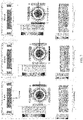
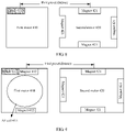
- a dual-camera device including a first motor and a second motor may be shown in FIG. 12 . It should be understood that a coil configured to support a magnet in a power-on state is disposed under a magnet in each second motor in FIG. 12 .
- the first motor is an open-loop AF motor
- the open-loop AF motor includes two magnets.
- the second motor is an open-loop OIS motor
- the open-loop OIS motor includes four magnets and one Hall effect sensor (Hall-X and Hall-Y) in each of an X-axis direction and a Y-axis direction. All or some of the magnets in the open-loop AF motor and the magnets in the open-loop OIS motor may be bipolar magnets.
- the first motor is a closed-loop AF motor
- the closed-loop AF motor includes two magnets and two Hall effect sensors (Hall-1 and Hall-2) in a Z-axis direction.
- the second motor is an open-loop OIS motor, and the open-loop OIS motor includes four magnets and one Hall effect sensor (Hall-X and Hall-Y) in each of an X-axis direction and a Y-axis direction. All or some of the magnets in the closed-loop AF motor and the magnets in the open-loop OIS motor may be bipolar magnets.
- the first motor is an open-loop AF motor
- the open-loop AF motor includes two magnets.
- the second motor is a closed-loop OIS motor
- the closed-loop OIS motor includes four magnets and one Hall effect sensor (Hall-X, Hall-Y, and Hall-Z) in each of an X-axis direction, a Y-axis direction, and a Z-axis direction. All or some of the magnets in the open-loop AF motor and the magnets in the closed-loop OIS motor may be bipolar magnets.
- the first motor is a closed-loop AF motor
- the closed-loop AF motor includes two magnets and two Hall effect sensors (Hall-1 and Hall-2) in a Z-axis direction.
- the second motor is a closed-loop OIS motor
- the closed-loop OIS motor includes four magnets and one Hall effect sensor (Hall-X, Hall-Y, and Hall-Z) in each of an X-axis direction, a Y-axis direction, and a Z-axis direction. All or some of the magnets in the closed-loop AF motor and the magnets in the closed-loop OIS motor may be bipolar magnets.
- both the first motor and the second motor may be OIS motors. This is not limited in this application.
- a housing material of the second motor may also use a weak magnetic material or a non-magnetic material, so that magnetic interference caused by the second motor to the first motor is further reduced.
- the housing material is SUS304 or SUS315.
- a housing material of the first motor may be the same as or different from the housing material of the second motor.
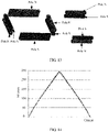
- FIG. 13 is a layout diagram of the magnets in the closed-loop AF motor and the magnets in the closed-loop OIS motor that are shown in (d) in FIG. 12 . Some of the magnets in FIG. 13 are bipolar magnets.
- FIG. 14 is a simulation diagram of magnetic interference of a structural layout of the bipolar magnets shown in FIG. 13.
- FIG. 14 is a diagram of simulation results of magnetic interference of a single AF closed-loop motor, a single closed-loop OIS motor, and a closed-loop AF motor and a closed-loop OIS motor. It can be seen from the figure that three lines almost coincide. In other words, when the closed-loop AF motor and the closed-loop OIS motor are laid out as shown in FIG. 13 and magnets are configured as bipolar magnets, magnetic interference is relatively weak.
- the locations of the Hall effect sensors and the magnets are laid out in the two motors, bipolar magnets are used as the magnets, and the housing materials of the motors are changed to the weak magnetic material or the non-magnetic material. This reduces magnetic interference between the two motors, so that user experience is improved.
- an embodiment of this application provides a terminal device, including the dual-camera device according to any one of the foregoing implementations.
- the terminal device includes but is not limited to a mobile phone, a mobile station, a tablet computer, a digital camera, or the like. This is not limited in this application.
- the terminal device when the terminal device is a mobile phone, the terminal device includes a dual-camera device, an image processing chip, a light sensitivity component, a display, and a battery.
- the terminal device when the terminal device is a digital camera, the terminal device includes a dual-camera device, an image processing chip, a light sensitivity component, an aperture, a display, a battery, a shutter, and the like. Details are not described in this embodiment of this application.
- a dual camera in this embodiment of this application may be two cameras on a back surface of a mobile phone that are disposed in parallel, or may be two cameras that are respectively disposed on a front surface and a back surface of a mobile phone. This is not limited in this application.
Landscapes
- Engineering & Computer Science (AREA)
- Signal Processing (AREA)
- Multimedia (AREA)
- Human Computer Interaction (AREA)
- Physics & Mathematics (AREA)
- General Physics & Mathematics (AREA)
- Adjustment Of Camera Lenses (AREA)
- Lens Barrels (AREA)
- Studio Devices (AREA)
- Camera Bodies And Camera Details Or Accessories (AREA)
- Cameras In General (AREA)
Description
- This application relates to the communications field, and more specifically, to a dual-camera device and a terminal device.
- Currently, application of a dual camera in a mobile phone is increasingly popularized. A dual camera usually includes two motors with a focus function. The motor measures and determines magnetic field intensity by disposing a Hall (Hall) effect sensor to determine a location of a lens, so as to implement focusing. In addition, a camera with a stabilization function is increasingly popularized, and the stabilization function is mainly implemented by using four magnets and four coils used to levitate and support the magnets in a power-on state.
- However, when a motor with a stabilization function is disposed in a dual-camera mobile phone, a strong magnetic field is generated by magnets and coils in a power-on state, and further strong magnetic interference is generated to a Hall effect sensor in another motor.
- In the prior art, the magnetic interference caused by the motor with the stabilization function in the dual-camera mobile phone to the Hall effect sensor in the another motor is avoided by using software. However, this causes deterioration of photographing experience (for example, a focus time). Therefore, a solution capable of reducing magnetic interference caused by a motor with a stabilization function in a dual camera to a motor with an autofocus function is urgently expected, to improve user experience.
-
WO 2016/156996 A1 describes dual-optical module autofocus (AF) or AF plus optical image stabilization (OIS) cameras with reduced footprint and reduced mutual magnetic interference. Some AF + OIS cameras may include a single AF actuation assembly that moves two lens barrels in unison. Some AF cameras or AF + OIS cameras may have two AF actuation sub-assemblies and associated magnets for independent AF operation of each lens barrel, the magnets shared in a manner that cancels magnetic influences of one AF actuation sub-assembly on the other AF actuation sub-assembly, thereby allowing the two lens barrels to be positioned in close proximity, saving parts and fabrication costs. -
CN105785547A describes another example of a dual camera having an automatic focusing mechanism. -
EP 3486718 A1 was cited during examination under Article 54(3) EPC for novelty only.EP 3486718 A1 describes a dual camera module comprising a first camera module and a second camera module, wherein: a first magnet unit of the first camera module includes a first magnet and a second magnet, both disposed opposite to each other on a side surface of a first housing; a second magnet unit of the second camera module includes a third to a sixth magnet arranged on four respective corners of a second housing; a third magnet unit is disposed on a side surface of the first housing facing the second housing; the third magnet unit is disposed between the first magnet and the second magnet; and the third magnet unit is smaller than the first magnet and is disposed on a virtual line connecting an optical axis of the first camera module and an optical axis of the second camera module. - Embodiments of this application provide a dual-camera device and a terminal device, so that magnetic interference caused by a motor with a stabilization function to a Hall effect sensor in another motor can be reduced, and user experience can be improved.
- According to a first aspect, a dual-camera device is provided, including: a first camera, where the first camera includes a first motor, and the first motor includes at least one first Hall effect sensor; and a second camera, where the second camera includes a second motor, the second motor and the first motor are disposed in parallel, the second motor includes N second coils and N second magnets, the second coils are configured to levitate and support the second magnets during power-on, N is a positive integer, and N is a multiple of 4. A distance between a first disposition location of the first Hall effect sensor in the first motor and a second disposition location of the second magnets in the second motor is greater than or equal to a first preset distance. Additionally, a housing material of the first motor or the second motor is a non-magnetic material. The first motor further includes M first coils and M first magnets, the first coils are configured to levitate and support the first magnets during power-on, M is a positive integer, and M is a multiple of 4; the second motor further includes at least one second Hall effect sensor, and a distance between a third disposition location of the second Hall effect sensor in the second motor and a fourth disposition location of the first magnets in the first motor is greater than or equal to a second preset distance.
- The distance between the Hall effect sensor in the first motor and the magnets in the second motor is greater than or equal to a first preset threshold, so that magnetic interference caused to the Hall effect sensor in the first motor by a magnetic field generated by the magnets in the second motor and the coils supporting the magnets in a power-on state is reduced, and user experience is improved.
- In some possible implementations, the first motor further includes K first magnets and an autofocus AF coil, the AF coil is in a ring shape, the K first magnets are placed opposite to each other along an outer wall of the ring shape, K is a positive integer, and K is a multiple of 2.
- The first motor may be an AF motor, and the second motor is a motor with a stabilization function. This reduces impact exerted on a focus function of the AF motor by the second motor, and reduces a focus time.
In this embodiment of this application, locations of a Hall effect sensor and a magnet are laid out in one motor and locations of a Hall effect sensor and a magnet are laid out in another motor, to reduce magnetic interference between the two motors, and user experience is improved. - In some possible implementations, the first motor further includes an AF coil, the AF coil is in a ring shape, and the M first magnets are placed pairwise opposite to each other around an outer wall of the ring shape.
- Locations of a Hall effect sensor and a magnet are laid out in an OIS motor and locations of a Hall effect sensor and a magnet are laid out in another motor, to reduce magnetic interference between the OIS motor and the motor with a stabilization function, so as to improve a focus function and a stabilization function of the OIS motor, and improve the stabilization function of the another motor.
- In some possible implementations, the second motor further includes an AF coil, the AF coil is in a ring shape, and the N second magnets are placed pairwise opposite to each other around an outer wall of the ring shape.
- Locations of a Hall effect sensor and a magnet are laid out in one OIS motor and locations of a Hall effect sensor and a magnet are laid out in another OIS motor, to reduce magnetic interference between the two OIS motors, and respectively improve focus functions and stabilization functions of the two OIS motors.
- In some possible implementations, the first magnets are bipolar magnets.
- Bipolar magnets may be used for the first motor to implement more desirable magnetic non-leakage, so that magnetic interference caused by the first motor to the Hall effect sensor in the second motor can be further reduced, and focus performance of the second motor can be improved.
- In some possible implementations, the second preset distance is a maximum value that can be reached by the distance between the third disposition location and the fourth disposition location.
- When a layout inside a motor is compact, the second preset distance may be configured as a maximum distance between the disposition location of the second Hall effect sensor and the location of the first magnets. In this way, interference caused by the first motor to the second Hall effect sensor can be reduced as much as possible.
- In some possible implementations, the second preset distance is 5 mm.
- When space inside a motor permits, a second preset threshold may be set to 5 mm, so that interference between the second Hall effect sensor and the first magnets is effectively reduced.
- In some possible implementations, the first preset distance is a maximum value that can be reached by the distance between the first disposition location and the second disposition location.
- When a layout inside a motor is compact, the first preset distance may be configured as a maximum distance between the disposition location of the first Hall effect sensor and the location of the second magnets. In this way, magnetic interference caused by the second motor to the first Hall effect sensor can be reduced as much as possible.
- In some possible implementations, the first preset distance is 5 mm.
- When space inside a motor permits, the first preset threshold may be set to 5 mm, so that interference caused by the second motor to the first Hall effect sensor is effectively reduced.
- In some possible implementations, the second magnets are bipolar magnets.
- Bipolar magnets may be used for the second motor to implement more desirable magnetic non-leakage, so that magnetic interference caused by the second motor to the Hall effect sensor in the first motor can be further reduced.
- In some possible implementations, a housing material of the first motor is SUS304 or SUS315.
- In some possible implementations, a housing material of the second motor is SUS304 or SUS315.
- According to a second aspect, a terminal device is provided, including the dual-camera device in any one of the first aspect and the possible implementations.
- Based on the foregoing technical solutions, the distance between the Hall effect sensor in the first motor and the magnets in the second motor is set to be greater than or equal to the first preset threshold in the embodiments of this application, so that magnetic interference caused to the Hall effect sensor in the first motor by the magnetic field generated by the magnets in the second motor and the coils supporting the magnets in a power-on state is reduced, and user experience is improved.
-
-
FIG. 1 is a schematic flowchart of an open loop and a closed loop; -
FIG. 2 is a schematic structural diagram of levitating and supporting magnets by coils in an optical image stabilization (optical image stabilization, OIS) motor; -
FIG. 3 is a diagram of an internal structure of an autofocus (Autofocus, AF) motor; -
FIG. 4 is a schematic diagram of a focus principle of an AF motor; -
FIG. 5 is a schematic diagram of force-bearing of an AF motor; -
FIG. 6 is a schematic structural diagram of an OIS motor; -
FIG. 7 is a schematic diagram of magnetic field intensity generated by an OIS motor in a power-on state; -
FIG. 8 is an elevational view of a motor structure of a dual-camera device according to an embodiment of this application; -
FIG. 9 is an elevational view of a motor structure of a dual-camera device according to another embodiment of this application; -
FIG. 10 is a schematic diagram of a bipolar magnet according to an embodiment of this application; -
FIG. 11 is an elevational view of a motor structure of a dual-camera device according to another embodiment of this application; -
FIG. 12 is an elevational view of a motor structure of a dual-camera device according to still another embodiment of this application; -
FIG. 13 is a layout diagram of bipolar magnets according to an embodiment of this application; and -
FIG. 14 is a diagram of a simulation result of magnetic interference according to an embodiment of this application. - The following describes the technical solutions in the embodiments of this application with reference to the accompanying drawings in the embodiments of this application.
- For ease of understanding the embodiments of this application, the following elements are first described before the embodiments of this application are described.
- A working principle of an autofocus (Autofocus, AF) motor is: A coil inside the motor is powered on to generate a magnetic field, a lens is moved based on magnetic force, and the AF motor measures and determines magnetic field intensity by using a Hall effect sensor to determine a location of the lens, moves the location of the entire lens by using a micro-distance, and controls a focal length, to implement clearness of an image. The AF motor mainly includes a voice coil motor, a stepper motor, liquid lens focus, a memory alloy motor, liquid crystal lens focus, and the like, and a most commonly used drive mechanism is the voice coil motor (Voice Coil Motor, VCM).
-
FIG. 1 is a flowchart of an open loop and a closed loop. The open loop has a simple structure and low costs, works stably, and has a relatively good control effect when an input signal and input disturbance can be known in advance. However, an offset of a controlled value cannot be automatically corrected, and an element parameter change in a system and external unknown disturbance affect control precision. - The closed loop has a capability of automatically correcting an offset of a controlled value by using feedback control, can correct an error caused by an element parameter change and external disturbance, and has high control precision. A closed-loop AF motor implements the foregoing function by using a Hall effect sensor, and the Hall effect sensor may measure and determine a Gaussian value in a magnetic field, so that a location of a lens can be further measured and determined. Specifically, magnetic field intensity at locations of 0 and max of the lens is sensed by using the Hall effect sensor and is stored in a driver. Magnetic field intensity at a movement location can also be measured during motion of a focus lens set, and the intensity is returned to the driver. The driver obtains a positive or negative error based on the returned value, and then controls a moving direction and a moving speed of the focus lens set by using the positive or negative error. In this way, focus may be performed relatively precisely and quickly.
- An autofocus function of an OIS motor is implemented by an AF coil and two magnets opposite to each other. An OIS function is implemented by a lens levitation body (shown in
FIG. 2 ) including four pairwise opposite magnets and four OIS coils. The OIS motor mainly includes a translation-type OIS focus motor and a shaft-moving-type focus motor. Principles of the two OIS motors are the same, to be specific, a lens is controlled to translate relative to an image sensor, so that an image offset caused by hand jitter is cancelled and compensated for. A type of the OIS motor is not limited in this embodiment of this application. - In conclusion, the AF motor adjusts a focal length through movement in a vertical direction, and the OIS motor not only can move a lens in the vertical direction, but also can move a lens in a horizontal direction. A gyroscope built in a terminal device converts jitter information into an electrical signal and sends the electrical signal to an OIS control driver. The OIS control driver drives a motor to control motion of a levitation lens to compensate for impact generated by jitter. The Hall effect sensor feeds back location information of the lens to the OIS control driver, to form complete closed-loop control.
-
FIG. 3 is a diagram of an internal structure of an autofocus (AF) motor. AF motors are further classified into an open-loop (open-loop) AF motor and a closed-loop (close loop) AF motor. The open-loop AF motor includes a cover 101 (cover), a yoke 102 (yoke), a top spring 103 (spring-top), a magnet 104 (magnet), a coil 105 (coil), a holder 106 (holder), a bottom spring 107 (spring-btm), a terminal 108 (terminal), and a base 109 (base). The closed-loop AF motor differs from the open-loop AF motor in that a bottom spring further includes a Hall magnet 110 (magnet Hall element), a Hall effect sensor 111 (Hall element), and a flexible circuit board 112 (FPC). It should be understood that the AF motor further includes a motor housing. - According to an autofocus principle, a lens is relatively remarkably moved by using a motor, to determine image contrast. A specific focus process includes the following steps:
- (1) When focus is not performed, an entire image of a focus point is in a defocus state.
- (2) Focus starts, the lens starts to move, the image gradually becomes clear, and the contrast starts to rise.
- (3) In a focus state, the image is the clearest with highest contrast, but this is unknown by a mobile phone; therefore, the lens continues to move.
- (4) The lens continues to move to find that the contrast starts to decrease; the lens is further moved to find that the contrast further decreases, and the mobile phone knows that the focus point is already missed.
- (5) The lens is moved back to a location with the highest contrast, to complete focus.
-
FIG. 4 shows the focus principle. The figure describes the focus process. After two clearest areas are found by moving a lens, the lens is then slightly moved in the two areas to find a clear focus point. The motor moves the lens by using Ampere's force, and a fixed magnetic field and a coil through which a variant current runs are needed. - A working principle of an autofocus motor is: In a permanent magnetic field, a stretching location of a spring plate is controlled by changing a value of a direct current in a coil inside the motor, to drive the lens to move up and down. For example, an autofocus work force-bearing situation shown in
FIG. 5 is: F=IL∗Bsinα and Fi=fs+gL, where F is Ampere's force, fs is elastic force of a spring, and gL is gravity of the lens. - The OIS motor has an autofocus function of the AF motor, and further has a stabilization function. The OIS motor usually includes four
magnets 310 andHall effect sensors 320 in an X-axis direction and in a Y-axis direction, and/orHall effect sensors 320 and a housing 330 that are in a Z-axis direction. The housing usually uses an aluminum material.FIG. 6 is a structural diagram of an OIS motor. Four magnets are fastened to a yoke around a periphery. After power-on, magnetic force is generated by a magneto and a coil, to push a lens carrier to move. Two Hall effect sensors in a Z-axis direction, four magnets, and a housing are included inFIG. 6 . The Hall effect sensors in the X-axis direction and in the Y-axis direction are configured to detect magnetic field changes in the X direction and in the Y direction, and the Hall effect sensors in the Z-axis direction are configured to detect a magnetic field change in the Z-axis direction. - One of two motors in a dual-camera device in the prior art has a stabilization function, and the other motor determines a location of a lens by measuring and determining magnetic field intensity by using a Hall effect sensor, to implement focus. The
Hall effect sensors 320 and themagnets 104 are disposed at random, and a corresponding coil is disposed under each magnet. Therefore, when the coil is powered on, strong magnetic interference is caused to the Hall in the AF motor by magnetic field force generated by the magnet and the coil. Consequently, a focus speed and stabilization performance of photographing deteriorate. For example,FIG. 7 shows the magnetic force generated by the coil and the magnet changes as a current in a powered-on coil in the OIS motor changes. To be specific, the magnetic force generated by the coil and the magnet increases as the power-on current increases from 0 mA to 100 mA. -
FIG. 8 is an elevational view of a motor structure of a dual-camera device according to an embodiment of this application. As shown inFIG. 8 , the dual-camera device includes: a first camera, where the first camera includes a first motor, and the first motor includes at least one first Hall Hall effect sensor; and a second camera, where the second camera includes a second motor, the second motor and the first motor are disposed in parallel, the second motor includes N second coils and N second magnets, the second coils are configured to levitate and support the second magnets during power-on, N is a positive integer, and N is a multiple of 4. A distance between a first disposition location of the first Hall effect sensor in the first motor and a second disposition location of the second magnets in the second motor is greater than or equal to a first preset distance. - Specifically, the
first motor 410 includes the at least one first Hall effect sensor, and thesecond motor 420 includes the N second magnets and the N second coils (that is, OIS coils). N is greater than 4 and is a multiple of 4. A specific quantity may be determined based on a module size in the motor, a distance between the two cameras, and the like. This is not limited in this application. - As shown in
FIG 8 , for ease of description, an example in which thefirst motor 410 includes one firstHall effect sensor 411 and thesecond motor 420 includes foursecond magnets 421 and four second coils (the coils are under the magnets, and this is not shown inFIG. 8 ) is used for description. The firstHall effect sensor 411 is disposed in thefirst motor 410, thesecond magnets 421 are disposed in thesecond motor 420, and the distance between the first disposition location and the second disposition location is greater than or equal to the first preset distance. Specifically, the sensors and the magnets may be laid out based on a magnetic field between the two motors, a sensitive area of the magnetic field is determined, and the disposition location of the Hall effect sensor in the first motor and the disposition location of the magnets in the second motor are laid out by using the magnetic sensitive area. - It should be understood that the first preset distance may alternatively be determined based on factors such as sizes of internal space of the two motors (to be specific, the first preset distance is less than or equal to a maximum distance between internal components of the two motors) and measured data, or may be set at delivery or may be set by a user based on a requirement. This is not limited in this application.
- It should be further understood that the distance between the first disposition location and the second disposition location in
FIG. 8 may be a distance between a center of theHall effect sensor 411 and a center of themagnets 421, may be a maximum distance between a left edge of theHall effect sensor 411 and a right edge of themagnets 421, may be a minimum distance between a right edge of theHall effect sensor 411 and a left edge of themagnets 421, may be a distance between a left edge of theHall effect sensor 411 and a left edge of themagnets 421, or the like. This is not limited in this application. In addition, for ease of description, an example in which theHall effect sensor 411 and themagnets 421 are on a same plane is used for description in this application. However, this application is not limited thereto. - It should be noted that if the first motor includes a plurality of first Hall effect sensors, and the second motor includes a plurality of second magnets, the distance between the first disposition location and the second disposition location may be a minimum value of a distance between a location of the plurality of first Hall effect sensors in the first motor and a location of the plurality of second magnets in the second motor.
- It should be understood that there is usually a gap between the two motors in the dual-camera device. The gap may be configured based on actual application, and is usually set to be less than 1.5 mm. This is not limited in this application.
- It should be further understood that mutual impact with another device in the dual-camera device should be further considered for the disposition location of the Hall effect sensors and the disposition location of the magnets in the motors. This is not limited in this embodiment of this application.
- Therefore, for the dual-camera device in this embodiment of this application, the distance between the Hall effect sensor in the first motor and the magnets in the second motor is set to be greater than or equal to the first preset threshold, so that magnetic interference caused to the Hall effect sensor in the first motor by the magnetic field generated by the magnets in the second motor and the coils supporting the magnets in a power-on state is reduced, and user experience is improved.
- Optionally, the first motor further includes K
first magnets 412 and anAF coil 413, theAF coil 413 is in a ring shape, the Kfirst magnets 412 are placed opposite to each other along an outer wall of the ring shape, K is a positive integer, and K is a multiple of 2. In this case, the first motor may be considered as an AF motor, and the second motor has a stabilization function. For example, as shown inFIG. 9, FIG. 9 is a schematic diagram of an example in which K is 2. - It should be noted that a quantity of Hall effect sensors in each direction may be determined based on a factor such as a module size in a motor. This is not limited herein in this application.
- Optionally, the first preset distance is a maximum value that can be reached by the first disposition location and the second disposition location.
- Specifically, when a layout inside a motor is compact, the first preset distance may be configured as a maximum distance between the disposition location of the first Hall effect sensor and the location of the second magnets. In this way, magnetic interference caused by the second motor to the first Hall effect sensor can be reduced as much as possible.
- Optionally, when space inside a motor permits, the first preset threshold may be set to 5 mm, so that magnetic interference caused by the second motor to the first Hall effect sensor is effectively reduced.
- Optionally, the second magnets are bipolar magnets.
- Specifically, the second motor may use a bipolar magnet (shown in
FIG. 10 ). There are two polarities on one surface of the bipolar magnet, and different from divergence of a unipolar magnet, an external magnetic field of the bipolar magnet is limited. Therefore, more desirable magnetic non-leakage can be implemented, so that magnetic interference caused by the second motor to the Hall effect sensor in the first motor can be further reduced. - It should be understood that all or some of the plurality of second magnets included in the second motor may be bipolar magnets. This is not limited in this application. For example, if the second motor includes four magnets that may be placed pairwise symmetrically. Two magnets that are symmetrically placed are configured as bipolar magnets, and the other two symmetrical magnets are common magnets.
- Optionally, a housing material of the first motor is SUS304 or SUS315.
- Specifically, the housing material of the first motor may use a weak magnetic material or a non-magnetic material, so that magnetic interference caused by the first motor to the second motor is further reduced. For example, the housing material may be SUS304, SUS315, or the like. The weak magnetic material or the non-magnetic material is not limited in this application.
- The first motor further includes M first coils and M first magnets, the first coils are configured to levitate and support the first magnets during power-on, M is a positive integer, and M is a multiple of 4. The second motor further includes at least one second Hall effect sensor, and a distance between a third disposition location of the second Hall effect sensor in the second motor and a fourth disposition location of the first magnets in the first motor is greater than or equal to a second preset distance.
- Specifically, if the first motor further includes the M first magnets and the M first coils (that is, OIS coils), the first motor also has a stabilization function. The second motor further includes the second Hall effect sensor, to be specific, the second motor also determines a location of a lens by detecting, measuring, and determining magnetic field intensity by using the Hall effect sensor. In this way, to avoid strong magnetic interference caused to the second Hall effect sensor by a magnetic field generated by the first magnets and the first coils, a distance between a third disposition location at which the first magnets are disposed in the first motor and a fourth disposition location at which the second Hall effect sensor is disposed in the second motor is greater than or equal to a second preset distance. As shown in
FIG. 11 , thefirst motor 410 further includes fourmagnets 412 and theHall effect sensor 411, thesecond motor 420 further includes theHall effect sensor 422, and a distance between theHall effect sensor 422 and themagnets 412 is greater than or equal to the second preset distance. - It should be understood that the second preset distance may be the same as the first preset distance. Details are not described herein again. Alternatively, the second preset distance may be different from the first preset threshold. This is not limited in this application.
- It should be further understood that magnetic interference between a Hall effect sensor and a magnet in a same motor may be calibrated during calibration of a production line because a module is a fixed value.
- Optionally, the first motor further includes an AF coil, the AF coil is in a ring shape, and the M first magnets are placed pairwise opposite to each other around an outer wall of the ring shape. In this case, the first motor may be considered as an OIS motor, and the second motor has a stabilization function.
- Optionally, the second motor further includes an AF coil, the AF coil is in a ring shape, and N second magnets are placed pairwise opposite to each other around an outer wall of the ring shape. In this case, both the first motor and the second motor may be OIS motors, in other words, both the two cameras have a stabilization function and a focus function.
- Optionally, the second preset distance is a maximum value that can be reached by the third disposition location and the fourth disposition location.
- Specifically, when a layout in a motor is compact, the second preset distance may be configured as a maximum distance between the disposition location (which is indicated as the third location) of the second Hall effect sensor and the disposition location (which is indicated as the fourth location) of the first magnets. In this way, interference caused by the first motor to the second Hall effect sensor can be reduced as much as possible.
- Optionally, when space inside a motor permits, a second preset threshold may be set to 5 mm, so that interference between the second Hall effect sensor and the first magnets is effectively reduced.
- Optionally, the first magnets may be bipolar magnets, and the first magnets may be the same as or different from the second magnets. This is not limited in this application.
- It should be understood that all or some of the M first magnets included in the first motor may be bipolar magnets. For example, a magnet that is in the first motor and that is close to the second motor uses a bipolar magnet, or a pair of magnets in some magnets that are disposed opposite to each other are bipolar magnets. This is not limited in this application.
- A dual-camera device including a first motor and a second motor may be shown in
FIG. 12 . It should be understood that a coil configured to support a magnet in a power-on state is disposed under a magnet in each second motor inFIG. 12 . - As shown in (a) in
FIG. 12 , the first motor is an open-loop AF motor, and the open-loop AF motor includes two magnets. The second motor is an open-loop OIS motor, and the open-loop OIS motor includes four magnets and one Hall effect sensor (Hall-X and Hall-Y) in each of an X-axis direction and a Y-axis direction. All or some of the magnets in the open-loop AF motor and the magnets in the open-loop OIS motor may be bipolar magnets. - As shown in (b) in
FIG. 12 , the first motor is a closed-loop AF motor, and the closed-loop AF motor includes two magnets and two Hall effect sensors (Hall-1 and Hall-2) in a Z-axis direction. The second motor is an open-loop OIS motor, and the open-loop OIS motor includes four magnets and one Hall effect sensor (Hall-X and Hall-Y) in each of an X-axis direction and a Y-axis direction. All or some of the magnets in the closed-loop AF motor and the magnets in the open-loop OIS motor may be bipolar magnets. - As shown in (c) in
FIG. 12 , the first motor is an open-loop AF motor, and the open-loop AF motor includes two magnets. The second motor is a closed-loop OIS motor, and the closed-loop OIS motor includes four magnets and one Hall effect sensor (Hall-X, Hall-Y, and Hall-Z) in each of an X-axis direction, a Y-axis direction, and a Z-axis direction. All or some of the magnets in the open-loop AF motor and the magnets in the closed-loop OIS motor may be bipolar magnets. - As shown in (d) in
FIG. 12 , the first motor is a closed-loop AF motor, and the closed-loop AF motor includes two magnets and two Hall effect sensors (Hall-1 and Hall-2) in a Z-axis direction. The second motor is a closed-loop OIS motor, and the closed-loop OIS motor includes four magnets and one Hall effect sensor (Hall-X, Hall-Y, and Hall-Z) in each of an X-axis direction, a Y-axis direction, and a Z-axis direction. All or some of the magnets in the closed-loop AF motor and the magnets in the closed-loop OIS motor may be bipolar magnets. - It should be understood that both the first motor and the second motor may be OIS motors. This is not limited in this application.
- Optionally, a housing material of the second motor may also use a weak magnetic material or a non-magnetic material, so that magnetic interference caused by the second motor to the first motor is further reduced. For example, the housing material is SUS304 or SUS315.
- It should be understood that a housing material of the first motor may be the same as or different from the housing material of the second motor.
- An example in which a dual-camera device includes a closed-loop AF motor and a closed-loop OIS motor is used for description.
FIG. 13 is a layout diagram of the magnets in the closed-loop AF motor and the magnets in the closed-loop OIS motor that are shown in (d) inFIG. 12 . Some of the magnets inFIG. 13 are bipolar magnets.FIG. 14 is a simulation diagram of magnetic interference of a structural layout of the bipolar magnets shown inFIG. 13. FIG. 14 is a diagram of simulation results of magnetic interference of a single AF closed-loop motor, a single closed-loop OIS motor, and a closed-loop AF motor and a closed-loop OIS motor. It can be seen from the figure that three lines almost coincide. In other words, when the closed-loop AF motor and the closed-loop OIS motor are laid out as shown inFIG. 13 and magnets are configured as bipolar magnets, magnetic interference is relatively weak. - Therefore, for the dual-camera device in this embodiment of this application, the locations of the Hall effect sensors and the magnets are laid out in the two motors, bipolar magnets are used as the magnets, and the housing materials of the motors are changed to the weak magnetic material or the non-magnetic material. This reduces magnetic interference between the two motors, so that user experience is improved.
- Optionally, an embodiment of this application provides a terminal device, including the dual-camera device according to any one of the foregoing implementations. The terminal device includes but is not limited to a mobile phone, a mobile station, a tablet computer, a digital camera, or the like. This is not limited in this application.
- Specifically, when the terminal device is a mobile phone, the terminal device includes a dual-camera device, an image processing chip, a light sensitivity component, a display, and a battery. When the terminal device is a digital camera, the terminal device includes a dual-camera device, an image processing chip, a light sensitivity component, an aperture, a display, a battery, a shutter, and the like. Details are not described in this embodiment of this application.
- It should be understood that a dual camera in this embodiment of this application may be two cameras on a back surface of a mobile phone that are disposed in parallel, or may be two cameras that are respectively disposed on a front surface and a back surface of a mobile phone. This is not limited in this application.
- A person skilled in the art may clearly learn that for ease and briefness of description, specific working processes of the dual-camera device and the terminal device that are described above are not described herein again.
The foregoing descriptions are merely specific implementations of this application, but are not intended to limit the protection scope of this application. The protection scope of this application shall be subject to the protection scope of the claims.
Claims (13)
- A dual-camera device, comprising:a first camera, wherein the first camera comprises a first motor (410), and the first motor comprises at least one first Hall effect sensor (411); anda second camera, wherein the second camera comprises a second motor (420), the second motor and the first motor are disposed in parallel, the second motor comprises N second coils and N second magnets (421), the second coils are configured to levitate and support the second magnets during power-on, N is a positive integer, and N is a multiple of 4, whereina distance between a first disposition location of the first Hall effect sensor in the first motor and a second disposition location of the second magnets in the second motor is greater than or equal to a first preset distance,wherein a housing material of the first motor or the second motor is a non-magnetic material, andthe first motor (410) further comprises M first coils and M first magnets (412), the first coils are configured to levitate and support the first magnets during power-on, M is a positive integer, and M is a multiple of 4; the second motor (420) further comprises at least one second Hall effect sensor (422), and a distance between a third disposition location of the second Hall effect sensor in the second motor and a fourth disposition location of the first magnets in the first motor is greater than or equal to a second preset distance.
- The dual-camera device according to claim 1, wherein the first motor (410) further comprises K first magnets (412) and an autofocus AF coil, the AF coil is in a ring shape, the K first magnets are placed opposite to each other along an outer wall of the ring shape, K is a positive integer, and K is a multiple of 2.
- The dual-camera device according to claim 1, wherein the first motor (410) further comprises an AF coil, the AF coil is in a ring shape, and the M first magnets (412) are placed pairwise opposite to each other around an outer wall of the ring shape.
- The dual-camera device according to claim 1 or 3, wherein the second preset distance is 5 mm.
- The dual-camera device according to claim 1 or 3, wherein the second preset distance is a maximum value that can be reached by the distance between the third disposition location and the fourth disposition location.
- The dual-camera device according to any one of claims 1 to 5, wherein the first magnets (412) are bipolar magnets.
- The dual-camera device according to any one of claims 1 to 6, wherein the first preset distance is a maximum value that can be reached by the distance between the first disposition location and the second disposition location.
- The dual-camera device according to any one of claims 1 to 6, wherein the first preset distance is 5 mm.
- The dual-camera device according to any one of claims 1 to 8, wherein the second magnets (421) are bipolar magnets.
- The dual-camera device according to any one of claims 1 to 9, wherein a housing material of the first motor (410) is SUS304 or SUS315.
- The dual-camera device according to any one of claims 1 to 10, wherein a housing material of the second motor (420) is SUS304 or SUS315.
- The dual-camera device according to any one of claims 1 to 11, wherein the second motor (420) further comprises an AF coil, the AF coil is in a ring shape, and the N second magnets (421) are placed pairwise opposite to each other around an outer wall of the ring shape.
- A terminal device, comprising:
the dual-camera device according to any one of claims 1 to 12.
Applications Claiming Priority (2)
| Application Number | Priority Date | Filing Date | Title |
|---|---|---|---|
| CN201610956637.7A CN108024068B (en) | 2016-11-03 | 2016-11-03 | Double-camera equipment and terminal equipment |
| PCT/CN2017/109151 WO2018082619A1 (en) | 2016-11-03 | 2017-11-02 | Dual-camera device and terminal device |
Publications (3)
| Publication Number | Publication Date |
|---|---|
| EP3531690A1 EP3531690A1 (en) | 2019-08-28 |
| EP3531690A4 EP3531690A4 (en) | 2019-11-06 |
| EP3531690B1 true EP3531690B1 (en) | 2023-01-04 |
Family
ID=62075697
Family Applications (1)
| Application Number | Title | Priority Date | Filing Date |
|---|---|---|---|
| EP17867360.4A Active EP3531690B1 (en) | 2016-11-03 | 2017-11-02 | Dual-camera device and terminal device |
Country Status (7)
| Country | Link |
|---|---|
| US (2) | US11108960B2 (en) |
| EP (1) | EP3531690B1 (en) |
| JP (1) | JP6806896B2 (en) |
| KR (1) | KR102206410B1 (en) |
| CN (1) | CN108024068B (en) |
| ES (1) | ES2941808T3 (en) |
| WO (1) | WO2018082619A1 (en) |
Families Citing this family (10)
| Publication number | Priority date | Publication date | Assignee | Title |
|---|---|---|---|---|
| CN108810389B (en) * | 2018-09-06 | 2023-08-01 | 惠州萨至德光电科技有限公司 | Double-camera motor |
| US11019241B1 (en) | 2018-09-11 | 2021-05-25 | Apple Inc. | Camera lens control during magnetic interference |
| CN109089033A (en) * | 2018-10-22 | 2018-12-25 | 惠州市桑莱士智能科技股份有限公司 | Camera module |
| CN109274880B (en) * | 2018-11-28 | 2020-10-30 | 维沃移动通信(杭州)有限公司 | Dual camera device and mobile terminal |
| CN111866237B (en) * | 2019-04-30 | 2022-06-03 | 北京小米移动软件有限公司 | Pop-up camera module and terminal |
| KR102884716B1 (en) * | 2019-06-13 | 2025-11-13 | 엘지이노텍 주식회사 | Camera module and Control method of camera module |
| CN110505329A (en) * | 2019-09-25 | 2019-11-26 | 维沃移动通信(杭州)有限公司 | Functional module group and electronic equipment |
| CN111447367B (en) * | 2020-05-08 | 2021-10-19 | Oppo广东移动通信有限公司 | Voice coil motor, driving method, camera module and computer readable storage medium |
| CN111641771B (en) * | 2020-06-30 | 2021-07-30 | 诚瑞光学(常州)股份有限公司 | A camera module, an electronic device with a shooting function |
| CN113596324B (en) * | 2021-07-13 | 2023-09-01 | 上海艾为电子技术股份有限公司 | Shooting module motor control method and system and electronic equipment |
Citations (1)
| Publication number | Priority date | Publication date | Assignee | Title |
|---|---|---|---|---|
| EP3486718A1 (en) * | 2016-07-13 | 2019-05-22 | LG Innotek Co., Ltd. | Dual camera module and optical device |
Family Cites Families (13)
| Publication number | Priority date | Publication date | Assignee | Title |
|---|---|---|---|---|
| US7253929B2 (en) | 2002-02-06 | 2007-08-07 | Quad/Tech, Inc. | Camera assembly for a printing press |
| JP4589410B2 (en) * | 2005-12-16 | 2010-12-01 | 旭化成エレクトロニクス株式会社 | Position detection device |
| JP2008139458A (en) * | 2006-11-30 | 2008-06-19 | Fujifilm Corp | Apparatus and method for preventing drop impact of camera shake correction optical apparatus |
| JP2008197388A (en) | 2007-02-13 | 2008-08-28 | Nikon Corp | Image blur correction device, lens barrel, optical equipment |
| JP6583601B2 (en) * | 2014-08-06 | 2019-10-02 | ミツミ電機株式会社 | Lens holder driving device and camera-equipped mobile terminal |
| JP2016180836A (en) * | 2015-03-24 | 2016-10-13 | パイオニアデジタルデザインアンドマニュファクチャリング株式会社 | Lens driving device |
| WO2016156996A1 (en) * | 2015-04-02 | 2016-10-06 | Corephotonics Ltd. | Dual voice coil motor structure in a dual-optical module camera |
| CN204741393U (en) * | 2015-06-26 | 2015-11-04 | 爱佩仪光电技术(深圳)有限公司 | Diamagnetic and disturb optics anti -shake voice coil motor |
| US10264188B2 (en) * | 2015-09-30 | 2019-04-16 | Apple Inc. | Mobile zoom using multiple optical image stabilization cameras |
| CN205665451U (en) * | 2016-04-14 | 2016-10-26 | 唐小川 | CD -ROM drive motor, camera and camera equipment |
| CN105785547A (en) * | 2016-04-27 | 2016-07-20 | 河南省皓泽电子有限公司 | Closed-loop single set control central guidance automatic focusing device used for dual cameras |
| CN106357990A (en) | 2016-08-29 | 2017-01-25 | 昆山丘钛微电子科技有限公司 | Dual-camera device with anti-vibration function |
| CN206077561U (en) | 2016-08-29 | 2017-04-05 | 昆山丘钛微电子科技有限公司 | The Double-camera device of tool stabilization function |
-
2016
- 2016-11-03 CN CN201610956637.7A patent/CN108024068B/en active Active
-
2017
- 2017-11-02 JP JP2019523820A patent/JP6806896B2/en not_active Expired - Fee Related
- 2017-11-02 WO PCT/CN2017/109151 patent/WO2018082619A1/en not_active Ceased
- 2017-11-02 US US16/347,144 patent/US11108960B2/en active Active
- 2017-11-02 EP EP17867360.4A patent/EP3531690B1/en active Active
- 2017-11-02 ES ES17867360T patent/ES2941808T3/en active Active
- 2017-11-02 KR KR1020197015129A patent/KR102206410B1/en not_active Expired - Fee Related
-
2021
- 2021-08-03 US US17/392,791 patent/US11601597B2/en active Active
Patent Citations (1)
| Publication number | Priority date | Publication date | Assignee | Title |
|---|---|---|---|---|
| EP3486718A1 (en) * | 2016-07-13 | 2019-05-22 | LG Innotek Co., Ltd. | Dual camera module and optical device |
Also Published As
| Publication number | Publication date |
|---|---|
| JP6806896B2 (en) | 2021-01-06 |
| EP3531690A4 (en) | 2019-11-06 |
| CN108024068B (en) | 2020-07-07 |
| US11108960B2 (en) | 2021-08-31 |
| JP2019536094A (en) | 2019-12-12 |
| KR20190069559A (en) | 2019-06-19 |
| CN108024068A (en) | 2018-05-11 |
| ES2941808T3 (en) | 2023-05-25 |
| EP3531690A1 (en) | 2019-08-28 |
| US20210368103A1 (en) | 2021-11-25 |
| US20190356858A1 (en) | 2019-11-21 |
| WO2018082619A1 (en) | 2018-05-11 |
| KR102206410B1 (en) | 2021-01-21 |
| US11601597B2 (en) | 2023-03-07 |
Similar Documents
| Publication | Publication Date | Title |
|---|---|---|
| US11601597B2 (en) | Dual-camera device and terminal device | |
| CN212723615U (en) | Camera module | |
| US9977254B2 (en) | Camera lens module | |
| CN213302731U (en) | Camera module | |
| CN107966868B (en) | OIS camera module | |
| KR102485461B1 (en) | Lens driving device, camera module and optical apparatus | |
| KR102125558B1 (en) | Camera module, position detector and position detection method | |
| KR20240167752A (en) | Camera device and optical apparatus | |
| KR102444766B1 (en) | Actuator, camera module, and camera mounting device | |
| US9964778B2 (en) | Camera lens module | |
| KR102421263B1 (en) | Triple camera device and terminal device | |
| KR20160146680A (en) | Actuator, Camera Module, and Mobile Terminal with Camera | |
| CN106537215A (en) | Lens holder drive device and camera-equipped portable terminal | |
| US11516398B2 (en) | Anti-vibration mechanism for imaging element, camera and electronic device | |
| KR101666087B1 (en) | Camera lens module | |
| KR20160082035A (en) | Lens driving unit and camera module including the same | |
| CN207081926U (en) | A kind of lens driver with stabilization function | |
| US10133086B2 (en) | Camera lens module | |
| US20220197048A1 (en) | Anti-vibration mechanism for camera device, optical system, camera and electronic device | |
| KR101694881B1 (en) | Camera lens module | |
| KR102861660B1 (en) | Linkage devices, camera modules, and electronic devices |
Legal Events
| Date | Code | Title | Description |
|---|---|---|---|
| STAA | Information on the status of an ep patent application or granted ep patent |
Free format text: STATUS: THE INTERNATIONAL PUBLICATION HAS BEEN MADE |
|
| PUAI | Public reference made under article 153(3) epc to a published international application that has entered the european phase |
Free format text: ORIGINAL CODE: 0009012 |
|
| STAA | Information on the status of an ep patent application or granted ep patent |
Free format text: STATUS: REQUEST FOR EXAMINATION WAS MADE |
|
| 17P | Request for examination filed |
Effective date: 20190520 |
|
| AK | Designated contracting states |
Kind code of ref document: A1 Designated state(s): AL AT BE BG CH CY CZ DE DK EE ES FI FR GB GR HR HU IE IS IT LI LT LU LV MC MK MT NL NO PL PT RO RS SE SI SK SM TR |
|
| AX | Request for extension of the european patent |
Extension state: BA ME |
|
| REG | Reference to a national code |
Ref country code: DE Ref legal event code: R079 Ref document number: 602017065285 Country of ref document: DE Free format text: PREVIOUS MAIN CLASS: H04N0005247000 Ipc: H04N0005225000 |
|
| A4 | Supplementary search report drawn up and despatched |
Effective date: 20191007 |
|
| RIC1 | Information provided on ipc code assigned before grant |
Ipc: H04N 5/225 20060101AFI20190930BHEP Ipc: H04N 5/247 20060101ALI20190930BHEP |
|
| DAV | Request for validation of the european patent (deleted) | ||
| DAX | Request for extension of the european patent (deleted) | ||
| STAA | Information on the status of an ep patent application or granted ep patent |
Free format text: STATUS: EXAMINATION IS IN PROGRESS |
|
| 17Q | First examination report despatched |
Effective date: 20210422 |
|
| GRAP | Despatch of communication of intention to grant a patent |
Free format text: ORIGINAL CODE: EPIDOSNIGR1 |
|
| STAA | Information on the status of an ep patent application or granted ep patent |
Free format text: STATUS: GRANT OF PATENT IS INTENDED |
|
| INTG | Intention to grant announced |
Effective date: 20220726 |
|
| RIN1 | Information on inventor provided before grant (corrected) |
Inventor name: LI, DELIANG Inventor name: LI, JUAN |
|
| GRAS | Grant fee paid |
Free format text: ORIGINAL CODE: EPIDOSNIGR3 |
|
| GRAA | (expected) grant |
Free format text: ORIGINAL CODE: 0009210 |
|
| STAA | Information on the status of an ep patent application or granted ep patent |
Free format text: STATUS: THE PATENT HAS BEEN GRANTED |
|
| AK | Designated contracting states |
Kind code of ref document: B1 Designated state(s): AL AT BE BG CH CY CZ DE DK EE ES FI FR GB GR HR HU IE IS IT LI LT LU LV MC MK MT NL NO PL PT RO RS SE SI SK SM TR |
|
| REG | Reference to a national code |
Ref country code: GB Ref legal event code: FG4D |
|
| REG | Reference to a national code |
Ref country code: DE Ref legal event code: R096 Ref document number: 602017065285 Country of ref document: DE |
|
| REG | Reference to a national code |
Ref country code: CH Ref legal event code: EP |
|
| REG | Reference to a national code |
Ref country code: AT Ref legal event code: REF Ref document number: 1542741 Country of ref document: AT Kind code of ref document: T Effective date: 20230115 |
|
| REG | Reference to a national code |
Ref country code: IE Ref legal event code: FG4D |
|
| REG | Reference to a national code |
Ref country code: LT Ref legal event code: MG9D |
|
| REG | Reference to a national code |
Ref country code: NL Ref legal event code: MP Effective date: 20230104 |
|
| REG | Reference to a national code |
Ref country code: ES Ref legal event code: FG2A Ref document number: 2941808 Country of ref document: ES Kind code of ref document: T3 Effective date: 20230525 |
|
| REG | Reference to a national code |
Ref country code: AT Ref legal event code: MK05 Ref document number: 1542741 Country of ref document: AT Kind code of ref document: T Effective date: 20230104 |
|
| PG25 | Lapsed in a contracting state [announced via postgrant information from national office to epo] |
Ref country code: NL Free format text: LAPSE BECAUSE OF FAILURE TO SUBMIT A TRANSLATION OF THE DESCRIPTION OR TO PAY THE FEE WITHIN THE PRESCRIBED TIME-LIMIT Effective date: 20230104 |
|
| PG25 | Lapsed in a contracting state [announced via postgrant information from national office to epo] |
Ref country code: RS Free format text: LAPSE BECAUSE OF FAILURE TO SUBMIT A TRANSLATION OF THE DESCRIPTION OR TO PAY THE FEE WITHIN THE PRESCRIBED TIME-LIMIT Effective date: 20230104 Ref country code: PT Free format text: LAPSE BECAUSE OF FAILURE TO SUBMIT A TRANSLATION OF THE DESCRIPTION OR TO PAY THE FEE WITHIN THE PRESCRIBED TIME-LIMIT Effective date: 20230504 Ref country code: NO Free format text: LAPSE BECAUSE OF FAILURE TO SUBMIT A TRANSLATION OF THE DESCRIPTION OR TO PAY THE FEE WITHIN THE PRESCRIBED TIME-LIMIT Effective date: 20230404 Ref country code: LV Free format text: LAPSE BECAUSE OF FAILURE TO SUBMIT A TRANSLATION OF THE DESCRIPTION OR TO PAY THE FEE WITHIN THE PRESCRIBED TIME-LIMIT Effective date: 20230104 Ref country code: LT Free format text: LAPSE BECAUSE OF FAILURE TO SUBMIT A TRANSLATION OF THE DESCRIPTION OR TO PAY THE FEE WITHIN THE PRESCRIBED TIME-LIMIT Effective date: 20230104 Ref country code: HR Free format text: LAPSE BECAUSE OF FAILURE TO SUBMIT A TRANSLATION OF THE DESCRIPTION OR TO PAY THE FEE WITHIN THE PRESCRIBED TIME-LIMIT Effective date: 20230104 Ref country code: AT Free format text: LAPSE BECAUSE OF FAILURE TO SUBMIT A TRANSLATION OF THE DESCRIPTION OR TO PAY THE FEE WITHIN THE PRESCRIBED TIME-LIMIT Effective date: 20230104 |
|
| PG25 | Lapsed in a contracting state [announced via postgrant information from national office to epo] |
Ref country code: SE Free format text: LAPSE BECAUSE OF FAILURE TO SUBMIT A TRANSLATION OF THE DESCRIPTION OR TO PAY THE FEE WITHIN THE PRESCRIBED TIME-LIMIT Effective date: 20230104 Ref country code: PL Free format text: LAPSE BECAUSE OF FAILURE TO SUBMIT A TRANSLATION OF THE DESCRIPTION OR TO PAY THE FEE WITHIN THE PRESCRIBED TIME-LIMIT Effective date: 20230104 Ref country code: IS Free format text: LAPSE BECAUSE OF FAILURE TO SUBMIT A TRANSLATION OF THE DESCRIPTION OR TO PAY THE FEE WITHIN THE PRESCRIBED TIME-LIMIT Effective date: 20230504 Ref country code: GR Free format text: LAPSE BECAUSE OF FAILURE TO SUBMIT A TRANSLATION OF THE DESCRIPTION OR TO PAY THE FEE WITHIN THE PRESCRIBED TIME-LIMIT Effective date: 20230405 Ref country code: FI Free format text: LAPSE BECAUSE OF FAILURE TO SUBMIT A TRANSLATION OF THE DESCRIPTION OR TO PAY THE FEE WITHIN THE PRESCRIBED TIME-LIMIT Effective date: 20230104 |
|
| REG | Reference to a national code |
Ref country code: DE Ref legal event code: R097 Ref document number: 602017065285 Country of ref document: DE |
|
| PG25 | Lapsed in a contracting state [announced via postgrant information from national office to epo] |
Ref country code: SM Free format text: LAPSE BECAUSE OF FAILURE TO SUBMIT A TRANSLATION OF THE DESCRIPTION OR TO PAY THE FEE WITHIN THE PRESCRIBED TIME-LIMIT Effective date: 20230104 Ref country code: RO Free format text: LAPSE BECAUSE OF FAILURE TO SUBMIT A TRANSLATION OF THE DESCRIPTION OR TO PAY THE FEE WITHIN THE PRESCRIBED TIME-LIMIT Effective date: 20230104 Ref country code: EE Free format text: LAPSE BECAUSE OF FAILURE TO SUBMIT A TRANSLATION OF THE DESCRIPTION OR TO PAY THE FEE WITHIN THE PRESCRIBED TIME-LIMIT Effective date: 20230104 Ref country code: DK Free format text: LAPSE BECAUSE OF FAILURE TO SUBMIT A TRANSLATION OF THE DESCRIPTION OR TO PAY THE FEE WITHIN THE PRESCRIBED TIME-LIMIT Effective date: 20230104 Ref country code: CZ Free format text: LAPSE BECAUSE OF FAILURE TO SUBMIT A TRANSLATION OF THE DESCRIPTION OR TO PAY THE FEE WITHIN THE PRESCRIBED TIME-LIMIT Effective date: 20230104 |
|
| PLBE | No opposition filed within time limit |
Free format text: ORIGINAL CODE: 0009261 |
|
| STAA | Information on the status of an ep patent application or granted ep patent |
Free format text: STATUS: NO OPPOSITION FILED WITHIN TIME LIMIT |
|
| PG25 | Lapsed in a contracting state [announced via postgrant information from national office to epo] |
Ref country code: SK Free format text: LAPSE BECAUSE OF FAILURE TO SUBMIT A TRANSLATION OF THE DESCRIPTION OR TO PAY THE FEE WITHIN THE PRESCRIBED TIME-LIMIT Effective date: 20230104 |
|
| 26N | No opposition filed |
Effective date: 20231005 |
|
| PG25 | Lapsed in a contracting state [announced via postgrant information from national office to epo] |
Ref country code: SI Free format text: LAPSE BECAUSE OF FAILURE TO SUBMIT A TRANSLATION OF THE DESCRIPTION OR TO PAY THE FEE WITHIN THE PRESCRIBED TIME-LIMIT Effective date: 20230104 |
|
| PG25 | Lapsed in a contracting state [announced via postgrant information from national office to epo] |
Ref country code: IT Free format text: LAPSE BECAUSE OF FAILURE TO SUBMIT A TRANSLATION OF THE DESCRIPTION OR TO PAY THE FEE WITHIN THE PRESCRIBED TIME-LIMIT Effective date: 20230104 |
|
| REG | Reference to a national code |
Ref country code: CH Ref legal event code: PL |
|
| PG25 | Lapsed in a contracting state [announced via postgrant information from national office to epo] |
Ref country code: MC Free format text: LAPSE BECAUSE OF FAILURE TO SUBMIT A TRANSLATION OF THE DESCRIPTION OR TO PAY THE FEE WITHIN THE PRESCRIBED TIME-LIMIT Effective date: 20230104 |
|
| PG25 | Lapsed in a contracting state [announced via postgrant information from national office to epo] |
Ref country code: LU Free format text: LAPSE BECAUSE OF NON-PAYMENT OF DUE FEES Effective date: 20231102 |
|
| PG25 | Lapsed in a contracting state [announced via postgrant information from national office to epo] |
Ref country code: CH Free format text: LAPSE BECAUSE OF NON-PAYMENT OF DUE FEES Effective date: 20231130 |
|
| PG25 | Lapsed in a contracting state [announced via postgrant information from national office to epo] |
Ref country code: MC Free format text: LAPSE BECAUSE OF FAILURE TO SUBMIT A TRANSLATION OF THE DESCRIPTION OR TO PAY THE FEE WITHIN THE PRESCRIBED TIME-LIMIT Effective date: 20230104 Ref country code: LU Free format text: LAPSE BECAUSE OF NON-PAYMENT OF DUE FEES Effective date: 20231102 Ref country code: CH Free format text: LAPSE BECAUSE OF NON-PAYMENT OF DUE FEES Effective date: 20231130 |
|
| REG | Reference to a national code |
Ref country code: BE Ref legal event code: MM Effective date: 20231130 |
|
| REG | Reference to a national code |
Ref country code: IE Ref legal event code: MM4A |
|
| PG25 | Lapsed in a contracting state [announced via postgrant information from national office to epo] |
Ref country code: IE Free format text: LAPSE BECAUSE OF NON-PAYMENT OF DUE FEES Effective date: 20231102 |
|
| PG25 | Lapsed in a contracting state [announced via postgrant information from national office to epo] |
Ref country code: BE Free format text: LAPSE BECAUSE OF NON-PAYMENT OF DUE FEES Effective date: 20231130 |
|
| PG25 | Lapsed in a contracting state [announced via postgrant information from national office to epo] |
Ref country code: IE Free format text: LAPSE BECAUSE OF NON-PAYMENT OF DUE FEES Effective date: 20231102 Ref country code: BE Free format text: LAPSE BECAUSE OF NON-PAYMENT OF DUE FEES Effective date: 20231130 |
|
| PG25 | Lapsed in a contracting state [announced via postgrant information from national office to epo] |
Ref country code: BG Free format text: LAPSE BECAUSE OF FAILURE TO SUBMIT A TRANSLATION OF THE DESCRIPTION OR TO PAY THE FEE WITHIN THE PRESCRIBED TIME-LIMIT Effective date: 20230104 |
|
| PG25 | Lapsed in a contracting state [announced via postgrant information from national office to epo] |
Ref country code: BG Free format text: LAPSE BECAUSE OF FAILURE TO SUBMIT A TRANSLATION OF THE DESCRIPTION OR TO PAY THE FEE WITHIN THE PRESCRIBED TIME-LIMIT Effective date: 20230104 |
|
| PG25 | Lapsed in a contracting state [announced via postgrant information from national office to epo] |
Ref country code: CY Free format text: LAPSE BECAUSE OF FAILURE TO SUBMIT A TRANSLATION OF THE DESCRIPTION OR TO PAY THE FEE WITHIN THE PRESCRIBED TIME-LIMIT; INVALID AB INITIO Effective date: 20171102 |
|
| PG25 | Lapsed in a contracting state [announced via postgrant information from national office to epo] |
Ref country code: HU Free format text: LAPSE BECAUSE OF FAILURE TO SUBMIT A TRANSLATION OF THE DESCRIPTION OR TO PAY THE FEE WITHIN THE PRESCRIBED TIME-LIMIT; INVALID AB INITIO Effective date: 20171102 |
|
| PGFP | Annual fee paid to national office [announced via postgrant information from national office to epo] |
Ref country code: GB Payment date: 20250930 Year of fee payment: 9 |
|
| PGFP | Annual fee paid to national office [announced via postgrant information from national office to epo] |
Ref country code: FR Payment date: 20250930 Year of fee payment: 9 |
|
| PG25 | Lapsed in a contracting state [announced via postgrant information from national office to epo] |
Ref country code: TR Free format text: LAPSE BECAUSE OF FAILURE TO SUBMIT A TRANSLATION OF THE DESCRIPTION OR TO PAY THE FEE WITHIN THE PRESCRIBED TIME-LIMIT Effective date: 20230104 |
|
| PGFP | Annual fee paid to national office [announced via postgrant information from national office to epo] |
Ref country code: DE Payment date: 20250930 Year of fee payment: 9 |
|
| PGFP | Annual fee paid to national office [announced via postgrant information from national office to epo] |
Ref country code: ES Payment date: 20251212 Year of fee payment: 9 |