EP3531684A1 - Image sensor system and image sensor - Google Patents
Image sensor system and image sensor Download PDFInfo
- Publication number
- EP3531684A1 EP3531684A1 EP18206157.2A EP18206157A EP3531684A1 EP 3531684 A1 EP3531684 A1 EP 3531684A1 EP 18206157 A EP18206157 A EP 18206157A EP 3531684 A1 EP3531684 A1 EP 3531684A1
- Authority
- EP
- European Patent Office
- Prior art keywords
- data
- light emitting
- memory
- emitting part
- time
- Prior art date
- Legal status (The legal status is an assumption and is not a legal conclusion. Google has not performed a legal analysis and makes no representation as to the accuracy of the status listed.)
- Granted
Links
Images

Classifications
-
- G—PHYSICS
- G01—MEASURING; TESTING
- G01M—TESTING STATIC OR DYNAMIC BALANCE OF MACHINES OR STRUCTURES; TESTING OF STRUCTURES OR APPARATUS, NOT OTHERWISE PROVIDED FOR
- G01M11/00—Testing of optical apparatus; Testing structures by optical methods not otherwise provided for
-
- H—ELECTRICITY
- H04—ELECTRIC COMMUNICATION TECHNIQUE
- H04N—PICTORIAL COMMUNICATION, e.g. TELEVISION
- H04N17/00—Diagnosis, testing or measuring for television systems or their details
- H04N17/002—Diagnosis, testing or measuring for television systems or their details for television cameras
-
- G—PHYSICS
- G01—MEASURING; TESTING
- G01R—MEASURING ELECTRIC VARIABLES; MEASURING MAGNETIC VARIABLES
- G01R31/00—Arrangements for testing electric properties; Arrangements for locating electric faults; Arrangements for electrical testing characterised by what is being tested not provided for elsewhere
- G01R31/26—Testing of individual semiconductor devices
- G01R31/2607—Circuits therefor
- G01R31/2632—Circuits therefor for testing diodes
- G01R31/2635—Testing light-emitting diodes, laser diodes or photodiodes
-
- G—PHYSICS
- G01—MEASURING; TESTING
- G01R—MEASURING ELECTRIC VARIABLES; MEASURING MAGNETIC VARIABLES
- G01R31/00—Arrangements for testing electric properties; Arrangements for locating electric faults; Arrangements for electrical testing characterised by what is being tested not provided for elsewhere
- G01R31/44—Testing lamps
-
- G—PHYSICS
- G03—PHOTOGRAPHY; CINEMATOGRAPHY; ANALOGOUS TECHNIQUES USING WAVES OTHER THAN OPTICAL WAVES; ELECTROGRAPHY; HOLOGRAPHY
- G03B—APPARATUS OR ARRANGEMENTS FOR TAKING PHOTOGRAPHS OR FOR PROJECTING OR VIEWING THEM; APPARATUS OR ARRANGEMENTS EMPLOYING ANALOGOUS TECHNIQUES USING WAVES OTHER THAN OPTICAL WAVES; ACCESSORIES THEREFOR
- G03B15/00—Special procedures for taking photographs; Apparatus therefor
- G03B15/02—Illuminating scene
- G03B15/03—Combinations of cameras with lighting apparatus; Flash units
- G03B15/05—Combinations of cameras with electronic flash apparatus; Electronic flash units
-
- H—ELECTRICITY
- H04—ELECTRIC COMMUNICATION TECHNIQUE
- H04N—PICTORIAL COMMUNICATION, e.g. TELEVISION
- H04N23/00—Cameras or camera modules comprising electronic image sensors; Control thereof
- H04N23/50—Constructional details
- H04N23/54—Mounting of pick-up tubes, electronic image sensors, deviation or focusing coils
-
- H—ELECTRICITY
- H04—ELECTRIC COMMUNICATION TECHNIQUE
- H04N—PICTORIAL COMMUNICATION, e.g. TELEVISION
- H04N23/00—Cameras or camera modules comprising electronic image sensors; Control thereof
- H04N23/56—Cameras or camera modules comprising electronic image sensors; Control thereof provided with illuminating means
-
- H—ELECTRICITY
- H05—ELECTRIC TECHNIQUES NOT OTHERWISE PROVIDED FOR
- H05B—ELECTRIC HEATING; ELECTRIC LIGHT SOURCES NOT OTHERWISE PROVIDED FOR; CIRCUIT ARRANGEMENTS FOR ELECTRIC LIGHT SOURCES, IN GENERAL
- H05B45/00—Circuit arrangements for operating light-emitting diodes [LED]
- H05B45/50—Circuit arrangements for operating light-emitting diodes [LED] responsive to malfunctions or undesirable behaviour of LEDs; responsive to LED life; Protective circuits
- H05B45/58—Circuit arrangements for operating light-emitting diodes [LED] responsive to malfunctions or undesirable behaviour of LEDs; responsive to LED life; Protective circuits involving end of life detection of LEDs
-
- G—PHYSICS
- G03—PHOTOGRAPHY; CINEMATOGRAPHY; ANALOGOUS TECHNIQUES USING WAVES OTHER THAN OPTICAL WAVES; ELECTROGRAPHY; HOLOGRAPHY
- G03B—APPARATUS OR ARRANGEMENTS FOR TAKING PHOTOGRAPHS OR FOR PROJECTING OR VIEWING THEM; APPARATUS OR ARRANGEMENTS EMPLOYING ANALOGOUS TECHNIQUES USING WAVES OTHER THAN OPTICAL WAVES; ACCESSORIES THEREFOR
- G03B2206/00—Systems for exchange of information between different pieces of apparatus, e.g. for exchanging trimming information, for photo finishing
Definitions
- the disclosure relates to an image sensor system and an image sensor used in a production line of a factory, etc.
- a system called image sensor In the production line of a factory, a system called image sensor is frequently used for automating inspection and management of products and saving labors.
- a configuration that connects a camera and an image processing device with a cable is commonly used for the system (see Patent Document 1).
- a processing-integrated image sensor has also been launched and the image sensor integrates the camera and the image processing device together so as to capture images and process the captured images with a single device.
- Such a processing-integrated image sensor is also called a "smart camera,” which may also be integrated with an integrating illumination device and lenses.
- a modular structure smart camera which respectively modularizes the illumination elements, lenses, and image capturing elements, and, from the user side, the user may freely combine the illumination elements, lenses, and image capturing elements as desired.
- a smart camera includes an illumination module, a lens module, an imaging element module, etc.
- the illumination module has a light emitting element such as an LED (Light Emitting Diode) and illuminates an object such as a product with use of the light emission of the light emitting element.
- the light quantity of the illumination module deteriorates with the number of years of use. Therefore, if the illumination module is continued to be used, the brightness of the illumination module may change even if the illumination module is used with the same setting value as that at the start of use.
- the conventional smart camera it is possible to monitor the deterioration of the whole system including the illumination module, the lens module, the imaging element module, etc., but it is not possible to monitor the deterioration of each module individually.
- a PD Photodiode
- problems such as cost increase and expansion of the substrate area occur.
- An embodiment of the disclosure provides a technique for monitoring deterioration of an illumination module.
- a first aspect of the disclosure provides an image sensor system including an image sensor and a prediction part.
- the image sensor includes an illumination module and a processing part.
- the illumination module includes a light emitting part for emitting light and a nonvolatile memory.
- the processing part stores a first data and a second data in the memory.
- the first data includes an electric parameter value when the light emitting part is applied with a power and a cumulative power-on time obtained by accumulating a time when the light emitting part is applied with the power.
- the second data includes a value obtained by multiplying the electric parameter value when the light emitting part is applied with the power by the cumulative power-on time.
- the prediction part obtains the first data or the second data from the memory and predicts a lifetime of the light emitting part based on the first data or the second data.
- the electric parameter value when the light emitting part is applied with the power and the cumulative power-on time by accumulating the time when the light emitting part is applied with the power can be obtained from the nonvolatile memory of the illumination module and the lifetime of the light emitting part can be predicted based on the electric parameter value and the cumulative power-on time.
- the value obtained by multiplying the electric parameter value when the light emitting part is applied with the power by the cumulative power-on time can be obtained from the nonvolatile memory of the illumination module, the lifetime of the light emitting part can be predicted based on the value obtained by multiplying the electric parameter value when the light emitting part is applied with the power by the cumulative power-on time.
- the user can recognize the lifetime of the light emitting part and consider the inspection and replacement time of the illumination module based on the prediction result of the lifetime of the light emitting part. Since the user can consider the inspection and replacement time of the illumination module, the user can perform preventive maintenance to prevent beforehand occurrence of a malfunction of the illumination module. Accordingly, the image sensor system capable of monitoring the deterioration of the illumination module is provided.
- the light emitting part is operable with a plurality of current values
- the processing part may store a third data and a fourth data in the memory.
- the third data includes a plurality of electric parameter values when the light emitting part is applied with the power and the cumulative power-on time for each of the plurality of electric parameter values.
- the fourth data includes values obtained by respectively multiplying the plurality of electric parameter values when the light emitting part is applied with the power by the cumulative power-on time for each of the plurality of electric parameter values.
- the prediction part may obtain the third data or the fourth data from the memory and predict the lifetime of the light emitting part based on the third data or the fourth data.
- the prediction part can predict the lifetime of the light emitting part based on the plurality of electric parameter values when the light emitting part is applied with the power and the cumulative power-on time for each of the plurality of electric parameter values.
- the prediction part can predict the lifetime of the light emitting part based on the values obtained by respectively multiplying the plurality of electric parameter values when the light emitting part is applied with the power by the cumulative power-on time for each of the plurality of electric parameter values. In this way, the prediction accuracy of the lifetime of the light emitting part is improved, and the user can recognize the lifetime of the light emitting part more accurately.
- the processing part may store a fifth data and a sixth data in the memory.
- the fifth data includes the electric parameter value greater than or equal to a first threshold value and the cumulative power-on time for the electric parameter value greater than or equal to the first threshold value.
- the sixth data includes a value obtained by multiplying the electric parameter value greater than or equal to a second threshold value by the cumulative power-on time for the electric parameter value greater than or equal to a second threshold value.
- the prediction part may obtain the fifth data or the sixth data from the memory and predict the lifetime of the light emitting part based on the fifth data or the sixth data.
- the electric parameter value greater than or equal to the first threshold value and the cumulative power-on time for the electric parameter value greater than or equal to the first threshold value are stored in the memory.
- the value obtained by multiplying the electric parameter value greater than or equal to the second threshold value by the cumulative power-on time for the electric parameter value greater than or equal to the second threshold value is stored in the memory. In this way, the number of times of writing to the memory can be reduced, and the period before reaching the limit of the number of times of writing to the memory can be extended.
- the processing part may store the first data or the second data in the memory at a predetermined time interval.
- the processing part may store the third data or the fourth data in the memory at a predetermined time interval.
- the processing part may store the fifth data or the sixth data in the memory at a predetermined time interval.
- a second aspect of the disclosure provides an image sensor including an illumination module, a control part and a prediction part.
- the illumination module includes a light emitting part for emitting light and a nonvolatile memory.
- the control part stores a first data and a second data in the memory.
- the first data includes an electric parameter value when the light emitting part is supplied with a power and a cumulative power-on time obtained by accumulating a time when the light emitting part is supplied with the power.
- the second data includes a value obtained by multiplying the electric parameter value when the light emitting part is supplied with the power by the cumulative power-on time.
- the prediction part obtains the first data or the second data from the memory and predicts a lifetime of the light emitting part based on the first data or the second data.
- the electric parameter value when the light emitting part is applied with the power and the cumulative power-on time by accumulating the time when the light emitting part is applied with the power can be obtained from the nonvolatile memory of the illumination module and the lifetime of the light emitting part can be predicted based on the electric parameter value and the cumulative power-on time.
- the value obtained by multiplying the electric parameter value when the light emitting part is applied with the power by the cumulative power-on time can be obtained from the nonvolatile memory of the illumination module, and the lifetime of the light emitting part can be predicted based on the value obtained by multiplying the electric parameter value when the light emitting part is applied with the power by the cumulative power-on time.
- the user can recognize the lifetime of the light emitting part and consider the inspection and replacement time of the illumination module based on the prediction result of the lifetime of the light emitting part. Accordingly, the image sensor capable of monitoring the deterioration of the illumination module is provided.
- a technique for monitoring the deterioration of the illumination module with use of a memory included in the illumination module can be provided.
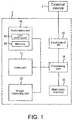
- FIG. 1 is a block diagram schematically showing a configuration of an image sensor system.
- the image sensor system includes an image sensor 1 and an external device 2.
- the image sensor 1 includes an illumination part 10, a lens part 11 and an imaging part 12 as an imaging system.
- the illumination part 10 has a light emitting part 20 and a nonvolatile memory 21.
- the light emitting part 20 has at least one light emitting element that emits light upon receiving a power from a power supply (not shown).
- the light emitting element is, for example, an LED.
- the illumination part 10 is a device for illuminating a subject (an object to be inspected, etc.) within a field of view of the image sensor 1 with use of the light emitted from the light emitting part 20.
- the image sensor 1 includes a main body memory 13, a processing part 14 and an input/output I/F 15 as a processing system.
- the processing part 14 is an example of a control part.
- the processing part 14 controls an imaging system and performs data transmission/reception and the like with an external device 2 via the input/output I/F 15.
- the processing part 14 stores a first data in the main body memory 13.
- the first data includes an electric parameter value when the light emitting part 20 is applied with the power and a cumulative power-on time by accumulating the time when the light emitting part 20 is applied with the power.
- the electric parameter value includes at least one of a current value, a voltage value, a VF (forward voltage) value, and a resistance value.
- the processing part 14 stores a second in the main body memory 13.
- the second data includes a value obtained by multiplying the electric parameter value when the light emitting part 20 is applied with the power by the cumulative power-on time.
- the processing part 14 stores the first data or the second data in the memory 21 at any timing or at a predetermined time interval.
- the processing part 14 obtains the first data or the second data from the memory 21 at any timing.
- the processing part 14 may obtain the first data or the second data from the memory 21 according to a request from the external device 2.
- the processing part 14 transmits the first data or the second data obtained from the memory 21 to the external device 2 at any timing.
- the external device 2 receives the first data or the second data and predicts the lifetime of the light emitting part 20 based on the received first data or the received second data. Further, the processing part 14 may predict the lifetime of the light emitting part 20 based on the first data or the second data obtained from the memory 21. The prediction result of the lifetime of the light emitting part 20 is displayed on a display device of the external device 2.
- the electric parameter value and the cumulative power-on time are stored in the memory 21 of the illumination part 10, and the lifetime of the light emitting part 20 is predicted based on the electric parameter value and the cumulative power-on time, and in this way, a user can consider the inspection and replacement time of the illumination part 10.
- the value obtained by multiplying the electric parameter value by the cumulative power-on time is stored in the memory 21 of the illumination part 10, and the lifetime of the light emitting part 20 is predicted based on the value obtained by multiplying the electric parameter value by the cumulative power-on time, and in this way, the user can consider the inspection and replacement time of the illumination part 10. In this way, it is possible to monitor the deterioration of the illumination module (the illumination part 10) which is one of a plurality of modules included in the image sensor 1.
- FIG. 1 is a block diagram schematically showing the configuration of the image sensor system.
- FIG. 2(A) is a perspective view schematically showing the appearance of the image sensor, and
- FIG. 2(B) is a perspective view schematically showing a state where the image sensor is disassembled.
- the image sensor 1 is a device installed in a production line of a factory, for example, and used for various processes using images.
- the image sensor 1 is also called a vision sensor or a vision system.
- the image sensor 1 of the first embodiment is a processing-integrated image sensor (the so-called smart camera) integrally formed by integrating an imaging system and a processing system.
- the image sensor 1 includes the illumination part 10, the lens part 11, and the imaging part 12 as the imaging system.
- the illumination part 10 is a device for illuminating a subject (an object to be inspected, etc.) within a field of view of the image sensor 1 and is composed of a plurality of light emitting elements (LEDs, etc.) arranged around the lens part 11, for example.
- the lens part 11 is an optical system for forming an optical image of the subject on the imaging part 12. For example, an optical system having functions such as focus adjustment, aperture, zoom, etc. is used.
- the imaging part 12 is a device for generating and outputting image data through photoelectric conversion and is composed of imaging elements such as CCD and CMOS, for example.
- the image sensor 1 includes the main body memory 13, the processing part 14 and the input/output I/F 15 as the processing system.
- the processing part 14 is a device for performing image processing (for example, preprocessing, feature amount extraction, etc.) on the image data taken from the imaging system, various processes based on the result of the image processing (for example, inspection, character recognition, individual identification, etc.), data transmission/reception with the external device 2 via the input/output I/F 15, generation of data to be outputted to the external device 2, processing of data received from the external device 2, control of the imaging system and the input/output I/F 15, etc.
- the processing part 14 stores current values when the light emitting part 20 is applied with the power and the cumulative power-on time in the main body memory 13 and the memory 21.
- the processing part 14 stores the current values (an example of the electric parameter value) in the main body memory 13 and the memory 21
- the processing part 14 may store a voltage value, a VF value, and a resistance value in the main body memory 13 and the memory 21.
- the current values when the light emitting part 20 is applied with the power (hereinafter simply referred to as "the current values") and the cumulative power-on time are temporarily stored in the main body memory 13.
- the main body memory 13 may be a volatile memory or a nonvolatile memory.
- the main body memory 13 may have any data capacity.
- the processing part 14 is composed of a processor and a memory, for example, and the processor reads and executes programs stored in the memory so as to realize the various processes described above.
- a part or all of the functions of the processing part 14 may be realized by an ASIC, an FPGA, etc. or may be provided by an external device.
- the input/output I/F 15 is a communication interface for transmitting/receiving data to/from the external device 2.
- the input/output I/F 15 includes a network interface for connecting to a PLC (Programmable Logic Controller, PLC) or a management terminal (computer), a parallel interface for connecting to another sensor or controller, etc.
- PLC Programmable Logic Controller
- the image sensor 1 of the first embodiment has a modular structure in which, as shown in FIG. 2(B) , the three modules, i.e., the illumination part 10, the lens part 11, and the imaging part 12, are selected and attached to a sensor body 16.
- the three modules i.e., the illumination part 10, the lens part 11, and the imaging part 12, are selected and attached to a sensor body 16.
- Each of the modules is fixed to the sensor body 16 by screw fastening, for example, and the user can attach/detach the module freely.
- modules are prepared to serve as the illumination part (illumination module) 10, such as modules with illumination lights of different wavelengths like white illumination/red illumination/infrared light illumination, and modules with different light emitting element arrangements, light quantities, or light emitting patterns.
- illumination module multiple types of light sources (LEDs, etc.) such as red, blue, green, and infrared light sources are provided in one module, and an illumination module that is capable of irradiating lights of wavelengths (for example, white, violet, pink, etc.) other than red, blue, green, and infrared through control of light emission of each light source may also be used.
- This type of illumination is called multi-color illumination, etc.
- modules module Multiple types are prepared to serve as the lens part (lens module) 11, such as a module having a function of adjusting the focus manually or automatically with use of an actuator, etc., a module with different fields of view such as a narrow field of view/a wide field of view, and a module having a zoom function.
- modules are prepared to serve as the imaging part (imaging module) 12, such as modules having different numbers of pixels, frame rates, and shutter types (rolling shutter/global shutter). The user can combine proper modules as appropriate according to the purpose or the required specification of the image sensor 1.
- the illumination part 10 has the light emitting part 20 for emitting light.
- the light emitting part 20 has at least one light emitting element that emits light upon receiving power supply from the power supply (not shown).
- the light emitting element is, for example, an LED.
- the current values applied to the light emitting part 20 are variable, and the light emitting part 20 is operable with a plurality of current values.
- the brightness of the illumination part 10 varies according to the current values flowing through the light emitting part 20.
- Power supply control current value switching, power on/off, etc.
- the processing part 14 stores the cumulative power-on time for each current value applied to the light emitting part 20 in the main body memory 13.
- the processing part 14 stores in the main body memory 13 the current values before change, the current values after change, the cumulative power-on time for the current values before change and the cumulative power-on time for the current values after change.
- the processing part 14 may store in the main body memory 13 a table 100 as shown in FIG. 3.
- FIG. 3 is a diagram showing an example of the table 100 stored in the main body memory 13.
- the plurality of current values is stored in the left field of the table 100. As shown in FIG. 3 , each of the plurality of current values may be a value within a certain range. Further, each of the plurality of current values may be a certain value.
- the cumulative power-on time for each of the plurality of current values is stored in the right field of the table 100. For example, the cumulative power-on time at factory shipment is set to 0h, and the plurality of current values and the cumulative power-on time for each of the plurality of current values are counted up after power is supplied to the illumination part 10.
- the processing part 14 stores the data including the plurality of current values and the cumulative power-on time for each of the plurality of current values (hereinafter simply referred to as "the plurality periods of cumulative power-on time") in the memory 21.
- the processing part 14 writes the data temporarily stored in the main body memory 13 to the memory 21.
- the processing part 14 writes the table 100 of FIG. 3 to the memory 21.
- the processing part 14 may erase the data of the main body memory 13 when the writing to the memory 21 is completed.
- EPROM Electrically Programmable Read Only Memory
- EEPROM Electrically Erasable Programmable Read Only Memory
- FeRAM Feroelectric Random Access Memory
- MRAM Magneticoresistive Random-Access Memory, MRAM
- the processing part 14 may store the plurality of current values and the plurality periods of cumulative power-on time in the memory 21 at a predetermined time interval. Specifically, the processing part 14 may store the plurality of current values per unit time and the plurality periods of cumulative power-on time per unit time in the memory 21 at a predetermined time interval. For example, the processing part 14 may store the plurality of current values per hour and the plurality periods of cumulative power-on time per hour in the memory 21 hourly. Since the memory 21 has a limit of the number of times of writing (lifetime), by storing the data in the memory 21 at a predetermined time interval, the number of times of writing to the memory 21 can be reduced. In this way, the period before reaching the limit of the number of times of writing to the memory 21 can be extended.
- lifetime the number of times of writing
- the limit of the number of times of writing to the EEPROM is about 100,000 times.
- the time before reaching the limit of the number of times of writing to the EEPROM is about seven years.
- the processing part 14 may store the plurality of current values and the plurality periods of cumulative power-on time in the memory 21 at any timing.
- the processing part 14 may store the current values greater than or equal to a threshold value and the cumulative power-on time for the current values greater than or equal to the threshold value in the memory 21.
- the current values in some cases do not affect the deterioration of the light emitting part 20.
- the number of times of writing to the memory 21 can be reduced. Further, the amount of data written in the memory 21 can be reduced.
- the processing part 14 may extract from the main body memory 13 the current values greater than or equal to the threshold value from the plurality of current values and the cumulative power-on time for the current values greater than or equal to the threshold value and store the extracted data in the memory 21.
- the processing part 14 may store in the memory 21 the average value of the plurality of current values applied to the light emitting part 20 and the total value of the cumulative power-on time for each of the plurality of current values. In this way, the amount of data written in the memory 21 can be reduced.
- the processing part 14 obtains the data stored in the memory 21 from the memory 21 at any timing. For example, the processing part 14 obtains the data including the plurality of current values and the plurality periods of cumulative power-on time from the memory 21 at any timing.
- the processing part 14 may obtain the data stored in the memory 21 from the memory 21 according to a request from the external device 2. For example, the processing part 14 may obtain the data including the plurality of current values and the plurality periods of cumulative power-on time from the memory 21 according to a request from the external device 2.
- the user can operate the external device 2 at a desired timing to retrieve the data including the plurality of current values and the plurality periods of cumulative power-on time from the memory 21.
- the processing part 14 transmits the data obtained from the memory 21 to the external device 2.
- the processing part 14 transmits the data including the plurality of current values and the plurality periods of cumulative power-on time to the external device 2. Further, the processing part 14 may transmit the data stored in the main body memory 13 to the external device 2 according to a request from the external device 2.
- the external device 2 includes a processing device such as a personal computer (PC), an external storage device such as a database (DB), a communication interface, a display device, etc.
- the processing device is composed of a processor such as a CPU (Central Processing Unit), a memory, etc.
- the external device 2 receives the data stored in the memory 21 from the image sensor 1. For example, the external device 2 receives the data including the plurality of current values and the plurality periods of cumulative power-on time from the image sensor 1.
- the processing device of the external device 2 predicts the lifetime of the light emitting part 20 based on the data stored in the memory 21.
- the processing device of the external device 2 predicts the lifetime of the light emitting part 20 based on the data including the plurality of current values and the plurality periods of cumulative power-on time.
- the processing device of the external device 2 may predict the lifetime of the light emitting part 20 by calculating the lifetime of the light emitting part 20 with use of a known lifetime calculation formula.
- the processing device of the external device 2 is an example of a prediction part.
- the processing device of the external device 2 may obtain other data used for predicting the lifetime of the light emitting part 20 from the database (DB).
- DB database
- the user can recognize the lifetime of the light emitting part 20.
- the user Based on the prediction result of the lifetime of the light emitting part 20, the user can consider the inspection and replacement time of the illumination part 10. In this way, according to the first embodiment, the illumination part 10 can be monitored.
- the illumination part 10 may be detached from the image sensor 1, and the detached illumination part 10 may be attached to another image sensor 1.
- the plurality of current values and the plurality periods of cumulative power-on time counted after the start of the power supply to the illumination part 10 are stored in the memory 21. Therefore, the external device 2 can obtain from the memory 21 the plurality of current values and the plurality periods of cumulative power-on time during the period from the start of the power supply to the illumination part 10 to the present. In this way, in the image sensor 1 of the first embodiment, even when the module is reassembled after the start of the power supply to the illumination part 10, the external device 2 can predict the lifetime of the light emitting part 20.
- the processing device of the external device 2 may determine the state of the light emitting part 20 based on the data stored in the memory 21. For example, the processing device of the external device 2 may determine the state of the light emitting part 20 based on the data including the plurality of current values and the plurality periods of cumulative power-on time.
- the state of the light emitting part 20 includes, for example, decrease of light quantity from a predetermined state of the light emitting part 20.
- the processing device of the external device 2 may determine the state of the light emitting part 20 by calculating the light output of the light emitting part 20 with use of a known deterioration calculation formula.
- the processing device of the external device 2 may obtain other data used for determining the state of the light emitting part 20 from the database (DB).
- the user can recognize the state of the light emitting part 20. Based on the determination result of the state of the light emitting part 20, the user can consider the inspection and replacement time of the illumination part 10. In this way, according to the first embodiment, the illumination part 10 can be monitored.
- the above shows an example in which the processing device of the external device 2 predicts the lifetime of the light emitting part 20 based on the current values and the cumulative power-on time.
- the processing device of the external device 2 may calculate the current values from voltage values, VF values and resistance values and predict the lifetime of the light emitting part 20 based on the current values and the cumulative power-on time.
- the processing device of the external device 2 predicts the lifetime of the light emitting part 20 based on the electric parameter value and the cumulative power-on time.
- the processing device of the external device 2 may predict the lifetime of the light emitting part 20 based on a plurality of electric parameter values and the plurality periods of cumulative power-on time. Further, the processing device of the external device 2 may determine the state of the light emitting part 20 based on the plurality of electric parameter values and the plurality periods of cumulative power-on time.
- the prediction of the lifetime of the light emitting part 20 may be performed by the following method.
- the degradation constant ( ⁇ 0 ) depends on the LED, and the activation energy (Ea) depends on the material of the LED.
- the temperature of the light emitting layer (Tj) can be calculated from the thermal resistance, power consumption, and ambient temperature depending on the LED.
- the processing device of the external device 2 calculates the light output (P) of the light emitting part 20 based on the current value and the cumulative power-on time with use of [Expression 1] and [Expression 2].
- the processing device of the external device 2 may calculate the light output (P) of the light emitting part 20 based on the plurality of current values and the plurality periods of cumulative power-on time with use of [Expression 1] and [Expression 2].
- the processing device of the external device 2 determines that the light emitting part 20 has reached the end of its lifetime when the light output (P) of the light emitting part 20 is less than or equal to a reference value.
- the processing device of the external device 2 determines that the state of the light emitting part 20 is bad when the light emitting part 20 has reached the end of its lifetime. The processing device of the external device 2 determines that the light emitting part 20 has not reached the end of its lifetime when the light output (P) of the light emitting part 20 is greater than the reference value. The processing device of the external device 2 determines that the state of the light emitting part 20 is good when the light emitting part 20 has not reached the end of its lifetime. The processing device of the external device 2 calculates the cumulative power-on time (t) when the light output (P) of the light emitting part 20 becomes less than or equal to the reference value with use of [Expression 1]. The processing device of the external device 2 may set the calculated cumulative power-on time (t) as the lifetime of the light emitting part 20.
- the processing device of the external device 2 predicts the lifetime of the light emitting part 20 based on the data including the plurality of current values and the plurality periods of cumulative power-on time obtained from the memory 21, but the disclosure is not limited to this example.
- the processing part 14 may predict the lifetime of the light emitting part 20 based on the data including the plurality of current values and the plurality periods of cumulative power-on time obtained from the memory 21.
- the processing part 14 may receive other data used for predicting the lifetime of the light emitting part 20 from the external device 2.
- the processing part 14 is an example of the prediction part.
- the processing part 14 transmits the prediction result of the lifetime the light emitting part 20 to the external device 2.
- the user can recognize the lifetime of the light emitting part 20. Based on the prediction result of the lifetime of the light emitting part 20, the user can consider the inspection and replacement time of the illumination part 10. In this way, according to the modified example of the first embodiment, the illumination part 10 can be monitored.
- the processing part 14 may perform prediction of the lifetime of the light emitting part 20 with the above-described method of ⁇ Lifetime Predictions
- the processing part 14 may determine the state of the light emitting part 20 based on the data including the plurality of current values and the plurality periods of cumulative power-on time obtained from the memory 21.
- the state of the light emitting part 20 includes, for example, decrease of light quantity from a predetermined state of the light emitting part 20.
- the processing part 14 may receive other data used for determining the state of the light emitting part 20 from the external device 2.
- the processing part 14 transmits the determination result of the state the light emitting part 20 to the external device 2.
- the user can recognize the state of the light emitting part 20.
- the user Based on the determination result of the state of the light emitting part 20, the user can consider the inspection and replacement time of the illumination part 10. In this way, according to the modified example of the first embodiment, the illumination part 10 can be monitored.
- the processing part 14 stores in the main body memory 13 the value obtained by multiplying the electric parameter value when the light emitting part 20 is applied with the power by the cumulative power-on time.
- the processing part 14 may store in the main body memory 13 a value obtained by multiplying the current value when the light emitting part 20 is applied with the power by the cumulative power-on time.
- the value obtained by multiplying the electric parameter value by the cumulative power-on time is temporarily stored in the main body memory 13.
- the processing part 14 stores the value obtained by multiplying the electric parameter value by the cumulative power-on time in the memory 21.
- the processing part 14 stores the values obtained by respectively multiplying the plurality of electric parameter values by the cumulative power-on time for each of the plurality of electric parameter values in the memory 21. In this case, the processing part 14 writes the data temporarily stored in the main body memory 13 to the memory 21.
- the processing part 14 may store the electric parameter value greater than or equal to the threshold value and the cumulative power-on time for the electric parameter value greater than or equal to the threshold value in the memory 21.
- the processing part 14 may store the value obtained by multiplying the electric parameter value when the light emitting part 20 is applied with the power by the cumulative power-on time in the memory 21 at a predetermined time interval.
- the processing part 14 may store the value obtained by multiplying the electric parameter value greater than or equal to the threshold value by the cumulative power-on time for the electric parameter value greater than or equal to the threshold value in the memory 21 at a predetermined time interval.
- the number of times of writing to the memory 21 can be reduced. Further, the amount of data written in the memory 21 can be reduced.
- the processing part 14 may store in the memory 21 a value obtained by multiplying the average value of the plurality of electric parameter values when the light emitting part 20 is applied with the power by the total value of the cumulative power-on time. In this way, the amount of data written in the memory 21 can be reduced.
- the processing part 14 obtains the data stored in the memory 21 from the memory 21 at any timing. For example, the processing part 14 obtains from the memory 21 the data including the value obtained by multiplying the electric parameter value by the cumulative power-on time at any timing.
- the processing part 14 may obtain the data stored in the memory 21 from the memory 21 according to a request from the external device 2. For example, the processing part 14 may obtain the data including the value obtained by multiplying the electric parameter value by the cumulative power-on time from the memory 21 according to a request from the external device 2.
- the user can operate the external device 2 at a desired timing to retrieve the data stored in the memory 21 from the memory 21.
- the processing part 14 transmits the data obtained from the memory 21 to the external device 2.
- the processing part 14 transmits the data including the value obtained by multiplying the electric parameter value by the cumulative power-on time to the external device 2. Further, the processing part 14 may transmit the data stored in the main body memory 13 to the external device 2 according to a request from the external device 2.
- the external device 2 receives the data stored in the memory 21 from the image sensor 1. For example, the external device 2 receives the data including the value obtained by multiplying the electric parameter value by the cumulative power-on time from the image sensor 1.
- the processing device of the external device 2 predicts the lifetime of the light emitting part 20 based on the data stored in the memory 21. For example, the processing device of the external device 2 predicts the lifetime of the light emitting part 20 based on the data including the value obtained by multiplying the electric parameter value by the cumulative power-on time.
- the processing device of the external device 2 may predict the lifetime of the light emitting part 20 based on the data including the value obtained by multiplying the current value by the cumulative power-on time.
- the processing device of the external device 2 may predict the lifetime of the light emitting part 20 by calculating the lifetime of the light emitting part 20 with use of a known lifetime calculation formula.
- the processing device of the external device 2 may obtain other data used for predicting the lifetime of the light emitting part 20 from the DB.
- the user With the prediction result of the lifetime of the light emitting part 20 displayed on the display device of the external device 2, the user can recognize the lifetime of the light emitting part 20. Based on the prediction result of the lifetime of the light emitting part 20, the user can consider the inspection and replacement time of the illumination part 10. In this way, according to the second embodiment, the illumination part 10 can be monitored.
- the external device 2 can predict the lifetime of the light emitting part 20. Further, the processing device of the external device 2 may determine the state of the light emitting part 20 based on the data stored in the memory 21. For example, the processing device of the external device 2 may determine the state of the light emitting part 20 based on the data including the value obtained by multiplying the electric parameter value by the cumulative power-on time.
- the above is an example in which the processing device of the external device 2 predicts the lifetime of the light emitting part 20 based on the data obtained from the memory 21, but the disclosure is not limited to this example.
- the processing part 14 may predict the lifetime of the light emitting part 20 based on the data obtained from the memory 21. For example, the processing part 14 may predict the lifetime of the light emitting part 20 based on the data including the value obtained by multiplying the electric parameter value by the cumulative power-on time. Further, the processing part 14 may predict the lifetime of the light emitting part 20 based on the data including the value obtained by multiplying the current value by the cumulative power-on time. In this case, the processing part 14 may receive other data used for predicting the lifetime of the light emitting part 20 from the external device 2.
- the processing part 14 transmits the prediction result of the lifetime the light emitting part 20 to the external device 2. With the prediction result of the lifetime of the light emitting part 20 displayed on the display device of the external device 2, the user can recognize the lifetime of the light emitting part 20. Based on the prediction result of the lifetime of the light emitting part 20, the user can consider the inspection and replacement time of the illumination part 10. In this way, according to the modified example of the second embodiment, the illumination part 10 can be monitored. Further, the processing part 14 may determine the state of the light emitting part 20 based on the data obtained from the memory 21. For example, the processing part 14 may determine the state of the light emitting part 20 based on the data including the value obtained by multiplying the electric parameter value by the cumulative power-on time.
- each of the above embodiments merely exemplifies a configuration example of the disclosure.
- the disclosure is not limited to the specific forms described above, and it is possible to make various modifications within the scope of the technical idea of the disclosure.
- the components to be attached to the image sensor are not limited thereto.
- an optical filter, the input/output I/F, the processing part (processor and memory), the display, etc. may also be modularized.
- the modules may be provided separately to be assembled on the user side, or the smart camera may be provided with the illumination module and the lens module incorporated in the sensor body. In the case of the latter form, there is no need to adjust the optical conditions on the user side, so it has the advantage that the image sensor can be introduced more easily.
Landscapes
- Engineering & Computer Science (AREA)
- Physics & Mathematics (AREA)
- General Physics & Mathematics (AREA)
- Multimedia (AREA)
- Signal Processing (AREA)
- Biomedical Technology (AREA)
- Health & Medical Sciences (AREA)
- General Health & Medical Sciences (AREA)
- Optics & Photonics (AREA)
- Chemical & Material Sciences (AREA)
- Analytical Chemistry (AREA)
- Circuit Arrangement For Electric Light Sources In General (AREA)
- Studio Devices (AREA)
- Photometry And Measurement Of Optical Pulse Characteristics (AREA)
Abstract
Description
- The disclosure relates to an image sensor system and an image sensor used in a production line of a factory, etc.
- In the production line of a factory, a system called image sensor is frequently used for automating inspection and management of products and saving labors. In the past, a configuration that connects a camera and an image processing device with a cable is commonly used for the system (see Patent Document 1). However, recently, a processing-integrated image sensor has also been launched and the image sensor integrates the camera and the image processing device together so as to capture images and process the captured images with a single device. Such a processing-integrated image sensor is also called a "smart camera," which may also be integrated with an integrating illumination device and lenses.
- Related Art is a patent document Japanese Laid-open No.
2007-214682 - In order to carry out stable inspection with the image sensor, it is desirable to optimize the model (type), specification and performance of the illuminations, lenses, and imaging elements according to an imaging environment, an object to be inspected, the purposes of the inspection, etc. Therefore, manufactures who provide smart cameras have lined up a large number of products such as illuminations, lenses, imaging elements, etc., with the different models (types), specifications and performances changed little by little, for the user to select the one with the optimum specification.
- However, as the IoT development of factories is accelerating, the range of application of smart cameras has been expanded, and it is becoming difficult to provide product variations that cover the diverse user needs. Further, in order to be distinguished from the competitors in product competition, more mass customization and seasonal products are offered to meet the preference of each customer and the life cycle of the products of digital devices typified by smart phones is shortening, and there is an increasing need for partially changing the illuminations and lenses, etc. to be optimized for the inspection as the change of the object to be inspected enters a short cycle. Thus, in the recent years, the so-called a modular structure smart camera has been introduced, which respectively modularizes the illumination elements, lenses, and image capturing elements, and, from the user side, the user may freely combine the illumination elements, lenses, and image capturing elements as desired. Such a smart camera includes an illumination module, a lens module, an imaging element module, etc. The illumination module has a light emitting element such as an LED (Light Emitting Diode) and illuminates an object such as a product with use of the light emission of the light emitting element. The light quantity of the illumination module deteriorates with the number of years of use. Therefore, if the illumination module is continued to be used, the brightness of the illumination module may change even if the illumination module is used with the same setting value as that at the start of use.
- In the conventional smart camera, it is possible to monitor the deterioration of the whole system including the illumination module, the lens module, the imaging element module, etc., but it is not possible to monitor the deterioration of each module individually. In addition, although it is conceivable to monitor the light quantity of the illumination module with use of a PD (Photodiode), since it is necessary to install the PD on the substrate of the illumination module, problems such as cost increase and expansion of the substrate area occur.
- An embodiment of the disclosure provides a technique for monitoring deterioration of an illumination module.
- In the disclosure, in order to solve the above problems, the following means are adopted. A first aspect of the disclosure provides an image sensor system including an image sensor and a prediction part. The image sensor includes an illumination module and a processing part. The illumination module includes a light emitting part for emitting light and a nonvolatile memory. The processing part stores a first data and a second data in the memory. The first data includes an electric parameter value when the light emitting part is applied with a power and a cumulative power-on time obtained by accumulating a time when the light emitting part is applied with the power. The second data includes a value obtained by multiplying the electric parameter value when the light emitting part is applied with the power by the cumulative power-on time. The prediction part obtains the first data or the second data from the memory and predicts a lifetime of the light emitting part based on the first data or the second data.
- According to this configuration, the electric parameter value when the light emitting part is applied with the power and the cumulative power-on time by accumulating the time when the light emitting part is applied with the power can be obtained from the nonvolatile memory of the illumination module and the lifetime of the light emitting part can be predicted based on the electric parameter value and the cumulative power-on time.
- According to this configuration, the value obtained by multiplying the electric parameter value when the light emitting part is applied with the power by the cumulative power-on time can be obtained from the nonvolatile memory of the illumination module, the lifetime of the light emitting part can be predicted based on the value obtained by multiplying the electric parameter value when the light emitting part is applied with the power by the cumulative power-on time.
- In this way, the user can recognize the lifetime of the light emitting part and consider the inspection and replacement time of the illumination module based on the prediction result of the lifetime of the light emitting part. Since the user can consider the inspection and replacement time of the illumination module, the user can perform preventive maintenance to prevent beforehand occurrence of a malfunction of the illumination module. Accordingly, the image sensor system capable of monitoring the deterioration of the illumination module is provided.
- In the image sensor system, the light emitting part is operable with a plurality of current values, and the processing part may store a third data and a fourth data in the memory. The third data includes a plurality of electric parameter values when the light emitting part is applied with the power and the cumulative power-on time for each of the plurality of electric parameter values. The fourth data includes values obtained by respectively multiplying the plurality of electric parameter values when the light emitting part is applied with the power by the cumulative power-on time for each of the plurality of electric parameter values. The prediction part may obtain the third data or the fourth data from the memory and predict the lifetime of the light emitting part based on the third data or the fourth data.
- According to this configuration, the prediction part can predict the lifetime of the light emitting part based on the plurality of electric parameter values when the light emitting part is applied with the power and the cumulative power-on time for each of the plurality of electric parameter values.
- According to this configuration, the prediction part can predict the lifetime of the light emitting part based on the values obtained by respectively multiplying the plurality of electric parameter values when the light emitting part is applied with the power by the cumulative power-on time for each of the plurality of electric parameter values. In this way, the prediction accuracy of the lifetime of the light emitting part is improved, and the user can recognize the lifetime of the light emitting part more accurately.
- In the image sensor system, the processing part may store a fifth data and a sixth data in the memory. The fifth data includes the electric parameter value greater than or equal to a first threshold value and the cumulative power-on time for the electric parameter value greater than or equal to the first threshold value. The sixth data includes a value obtained by multiplying the electric parameter value greater than or equal to a second threshold value by the cumulative power-on time for the electric parameter value greater than or equal to a second threshold value. The prediction part may obtain the fifth data or the sixth data from the memory and predict the lifetime of the light emitting part based on the fifth data or the sixth data.
- According to this configuration, the electric parameter value greater than or equal to the first threshold value and the cumulative power-on time for the electric parameter value greater than or equal to the first threshold value are stored in the memory. According to this configuration, the value obtained by multiplying the electric parameter value greater than or equal to the second threshold value by the cumulative power-on time for the electric parameter value greater than or equal to the second threshold value is stored in the memory. In this way, the number of times of writing to the memory can be reduced, and the period before reaching the limit of the number of times of writing to the memory can be extended.
- In the image sensor system, the processing part may store the first data or the second data in the memory at a predetermined time interval. In the image sensor system, the processing part may store the third data or the fourth data in the memory at a predetermined time interval. In the image sensor system, the processing part may store the fifth data or the sixth data in the memory at a predetermined time interval. According to this configuration, since the data is stored in the memory at a predetermined time interval, the number of times of writing to the memory can be reduced, and the period before reaching the limit of the number of times of writing to the memory can be extended.
- A second aspect of the disclosure provides an image sensor including an illumination module, a control part and a prediction part. The illumination module includes a light emitting part for emitting light and a nonvolatile memory. The control part stores a first data and a second data in the memory. The first data includes an electric parameter value when the light emitting part is supplied with a power and a cumulative power-on time obtained by accumulating a time when the light emitting part is supplied with the power. The second data includes a value obtained by multiplying the electric parameter value when the light emitting part is supplied with the power by the cumulative power-on time. The prediction part obtains the first data or the second data from the memory and predicts a lifetime of the light emitting part based on the first data or the second data.
- According to this configuration, the electric parameter value when the light emitting part is applied with the power and the cumulative power-on time by accumulating the time when the light emitting part is applied with the power can be obtained from the nonvolatile memory of the illumination module and the lifetime of the light emitting part can be predicted based on the electric parameter value and the cumulative power-on time.
- According to this configuration, the value obtained by multiplying the electric parameter value when the light emitting part is applied with the power by the cumulative power-on time can be obtained from the nonvolatile memory of the illumination module, and the lifetime of the light emitting part can be predicted based on the value obtained by multiplying the electric parameter value when the light emitting part is applied with the power by the cumulative power-on time.
- In this way, the user can recognize the lifetime of the light emitting part and consider the inspection and replacement time of the illumination module based on the prediction result of the lifetime of the light emitting part. Accordingly, the image sensor capable of monitoring the deterioration of the illumination module is provided.
- According to the disclosure, a technique for monitoring the deterioration of the illumination module with use of a memory included in the illumination module can be provided.
-
-
FIG. 1 is a block diagram schematically showing the configuration of an image sensor system. -
FIG. 2(A) is a perspective view schematically showing the appearance of an image sensor, andFIG. 2(B) is a perspective view schematically showing a state where the image sensor is disassembled. -
FIG. 3 is a diagram showing an example of a table stored in a main body memory. - First, an example of the scene to which the disclosure is applied will be described.
FIG. 1 is a block diagram schematically showing a configuration of an image sensor system. The image sensor system includes an image sensor 1 and an external device 2. The image sensor 1 includes anillumination part 10, alens part 11 and animaging part 12 as an imaging system. Theillumination part 10 has alight emitting part 20 and anonvolatile memory 21. Thelight emitting part 20 has at least one light emitting element that emits light upon receiving a power from a power supply (not shown). The light emitting element is, for example, an LED. Theillumination part 10 is a device for illuminating a subject (an object to be inspected, etc.) within a field of view of the image sensor 1 with use of the light emitted from thelight emitting part 20. Further, the image sensor 1 includes amain body memory 13, aprocessing part 14 and an input/output I/F 15 as a processing system. Theprocessing part 14 is an example of a control part. Theprocessing part 14 controls an imaging system and performs data transmission/reception and the like with an external device 2 via the input/output I/F 15. Theprocessing part 14 stores a first data in themain body memory 13. The first data includes an electric parameter value when thelight emitting part 20 is applied with the power and a cumulative power-on time by accumulating the time when thelight emitting part 20 is applied with the power. The electric parameter value includes at least one of a current value, a voltage value, a VF (forward voltage) value, and a resistance value. Theprocessing part 14 stores a second in themain body memory 13. The second data includes a value obtained by multiplying the electric parameter value when thelight emitting part 20 is applied with the power by the cumulative power-on time. Theprocessing part 14 stores the first data or the second data in thememory 21 at any timing or at a predetermined time interval. Theprocessing part 14 obtains the first data or the second data from thememory 21 at any timing. Theprocessing part 14 may obtain the first data or the second data from thememory 21 according to a request from the external device 2. - The
processing part 14 transmits the first data or the second data obtained from thememory 21 to the external device 2 at any timing. The external device 2 receives the first data or the second data and predicts the lifetime of thelight emitting part 20 based on the received first data or the received second data. Further, theprocessing part 14 may predict the lifetime of thelight emitting part 20 based on the first data or the second data obtained from thememory 21. The prediction result of the lifetime of thelight emitting part 20 is displayed on a display device of the external device 2. Therefore, the electric parameter value and the cumulative power-on time are stored in thememory 21 of theillumination part 10, and the lifetime of thelight emitting part 20 is predicted based on the electric parameter value and the cumulative power-on time, and in this way, a user can consider the inspection and replacement time of theillumination part 10. Further, the value obtained by multiplying the electric parameter value by the cumulative power-on time is stored in thememory 21 of theillumination part 10, and the lifetime of thelight emitting part 20 is predicted based on the value obtained by multiplying the electric parameter value by the cumulative power-on time, and in this way, the user can consider the inspection and replacement time of theillumination part 10. In this way, it is possible to monitor the deterioration of the illumination module (the illumination part 10) which is one of a plurality of modules included in the image sensor 1. - The image sensor system according to the first embodiment of the disclosure will be described with reference to
FIG. 1 ,FIG. 2(A) and FIG. 2(B) .FIG. 1 is a block diagram schematically showing the configuration of the image sensor system.FIG. 2(A) is a perspective view schematically showing the appearance of the image sensor, andFIG. 2(B) is a perspective view schematically showing a state where the image sensor is disassembled. - The image sensor 1 is a device installed in a production line of a factory, for example, and used for various processes using images. The image sensor 1 is also called a vision sensor or a vision system. The image sensor 1 of the first embodiment is a processing-integrated image sensor (the so-called smart camera) integrally formed by integrating an imaging system and a processing system.
- The image sensor 1 includes the
illumination part 10, thelens part 11, and theimaging part 12 as the imaging system. Theillumination part 10 is a device for illuminating a subject (an object to be inspected, etc.) within a field of view of the image sensor 1 and is composed of a plurality of light emitting elements (LEDs, etc.) arranged around thelens part 11, for example. Thelens part 11 is an optical system for forming an optical image of the subject on theimaging part 12. For example, an optical system having functions such as focus adjustment, aperture, zoom, etc. is used. Theimaging part 12 is a device for generating and outputting image data through photoelectric conversion and is composed of imaging elements such as CCD and CMOS, for example. - The image sensor 1 includes the
main body memory 13, theprocessing part 14 and the input/output I/F 15 as the processing system. Theprocessing part 14 is a device for performing image processing (for example, preprocessing, feature amount extraction, etc.) on the image data taken from the imaging system, various processes based on the result of the image processing (for example, inspection, character recognition, individual identification, etc.), data transmission/reception with the external device 2 via the input/output I/F 15, generation of data to be outputted to the external device 2, processing of data received from the external device 2, control of the imaging system and the input/output I/F 15, etc. Theprocessing part 14 stores current values when thelight emitting part 20 is applied with the power and the cumulative power-on time in themain body memory 13 and thememory 21. In the following, an example in which theprocessing part 14 stores the current values (an example of the electric parameter value) in themain body memory 13 and thememory 21 will be described, but the disclosure is not limited to this example, and theprocessing part 14 may store a voltage value, a VF value, and a resistance value in themain body memory 13 and thememory 21. The current values when thelight emitting part 20 is applied with the power (hereinafter simply referred to as "the current values") and the cumulative power-on time are temporarily stored in themain body memory 13. Themain body memory 13 may be a volatile memory or a nonvolatile memory. Themain body memory 13 may have any data capacity. - The
processing part 14 is composed of a processor and a memory, for example, and the processor reads and executes programs stored in the memory so as to realize the various processes described above. A part or all of the functions of theprocessing part 14 may be realized by an ASIC, an FPGA, etc. or may be provided by an external device. The input/output I/F 15 is a communication interface for transmitting/receiving data to/from the external device 2. For example, the input/output I/F 15 includes a network interface for connecting to a PLC (Programmable Logic Controller, PLC) or a management terminal (computer), a parallel interface for connecting to another sensor or controller, etc. - The image sensor 1 of the first embodiment has a modular structure in which, as shown in
FIG. 2(B) , the three modules, i.e., theillumination part 10, thelens part 11, and theimaging part 12, are selected and attached to asensor body 16. Each of the modules is fixed to thesensor body 16 by screw fastening, for example, and the user can attach/detach the module freely. - Multiple types of modules are prepared to serve as the illumination part (illumination module) 10, such as modules with illumination lights of different wavelengths like white illumination/red illumination/infrared light illumination, and modules with different light emitting element arrangements, light quantities, or light emitting patterns. Further, multiple types of light sources (LEDs, etc.) such as red, blue, green, and infrared light sources are provided in one module, and an illumination module that is capable of irradiating lights of wavelengths (for example, white, violet, pink, etc.) other than red, blue, green, and infrared through control of light emission of each light source may also be used. This type of illumination is called multi-color illumination, etc. Multiple types of modules are prepared to serve as the lens part (lens module) 11, such as a module having a function of adjusting the focus manually or automatically with use of an actuator, etc., a module with different fields of view such as a narrow field of view/a wide field of view, and a module having a zoom function. Multiple types of modules are prepared to serve as the imaging part (imaging module) 12, such as modules having different numbers of pixels, frame rates, and shutter types (rolling shutter/global shutter). The user can combine proper modules as appropriate according to the purpose or the required specification of the image sensor 1.
- The
illumination part 10 has thelight emitting part 20 for emitting light. Thelight emitting part 20 has at least one light emitting element that emits light upon receiving power supply from the power supply (not shown). The light emitting element is, for example, an LED. The current values applied to thelight emitting part 20 are variable, and thelight emitting part 20 is operable with a plurality of current values. The brightness of theillumination part 10 varies according to the current values flowing through thelight emitting part 20. Power supply control (current value switching, power on/off, etc.) for thelight emitting part 20 is performed by theprocessing part 14. Theprocessing part 14 stores the cumulative power-on time for each current value applied to thelight emitting part 20 in themain body memory 13. That is, theprocessing part 14 stores in themain body memory 13 the current values before change, the current values after change, the cumulative power-on time for the current values before change and the cumulative power-on time for the current values after change. For example, theprocessing part 14 may store in the main body memory 13 a table 100 as shown inFIG. 3. FIG. 3 is a diagram showing an example of the table 100 stored in themain body memory 13. The plurality of current values is stored in the left field of the table 100. As shown inFIG. 3 , each of the plurality of current values may be a value within a certain range. Further, each of the plurality of current values may be a certain value. The cumulative power-on time for each of the plurality of current values is stored in the right field of the table 100. For example, the cumulative power-on time at factory shipment is set to 0h, and the plurality of current values and the cumulative power-on time for each of the plurality of current values are counted up after power is supplied to theillumination part 10. - The
processing part 14 stores the data including the plurality of current values and the cumulative power-on time for each of the plurality of current values (hereinafter simply referred to as "the plurality periods of cumulative power-on time") in thememory 21. In this case, theprocessing part 14 writes the data temporarily stored in themain body memory 13 to thememory 21. For example, when the table 100 ofFIG. 3 is stored in themain body memory 13, theprocessing part 14 writes the table 100 ofFIG. 3 to thememory 21. Theprocessing part 14 may erase the data of themain body memory 13 when the writing to thememory 21 is completed. For example, EPROM (Electrically Programmable Read Only Memory, EPROM), EEPROM (Electrically Erasable Programmable Read Only Memory, EEPROM), FeRAM (Ferroelectric Random Access Memory , FeRAM), MRAM (Magnetoresistive Random-Access Memory, MRAM), etc. can be used as thememory 21, and thememory 21 may have any data capacity. - The
processing part 14 may store the plurality of current values and the plurality periods of cumulative power-on time in thememory 21 at a predetermined time interval. Specifically, theprocessing part 14 may store the plurality of current values per unit time and the plurality periods of cumulative power-on time per unit time in thememory 21 at a predetermined time interval. For example, theprocessing part 14 may store the plurality of current values per hour and the plurality periods of cumulative power-on time per hour in thememory 21 hourly. Since thememory 21 has a limit of the number of times of writing (lifetime), by storing the data in thememory 21 at a predetermined time interval, the number of times of writing to thememory 21 can be reduced. In this way, the period before reaching the limit of the number of times of writing to thememory 21 can be extended. For example, the limit of the number of times of writing to the EEPROM is about 100,000 times. When data is stored in the EEPROM hourly, the time before reaching the limit of the number of times of writing to the EEPROM is about seven years. Further, theprocessing part 14 may store the plurality of current values and the plurality periods of cumulative power-on time in thememory 21 at any timing. - The
processing part 14 may store the current values greater than or equal to a threshold value and the cumulative power-on time for the current values greater than or equal to the threshold value in thememory 21. Depending on the value of the current values flowing through thelight emitting part 20, the current values in some cases do not affect the deterioration of thelight emitting part 20. By not storing in thememory 21 the current values that do not affect the deterioration of thelight emitting part 20 and the cumulative power-on time of the current values that do not affect the deterioration of thelight emitting part 20, the number of times of writing to thememory 21 can be reduced. Further, the amount of data written in thememory 21 can be reduced. When the plurality of current values and the plurality periods of cumulative power-on time are stored in themain body memory 13, theprocessing part 14 may extract from themain body memory 13 the current values greater than or equal to the threshold value from the plurality of current values and the cumulative power-on time for the current values greater than or equal to the threshold value and store the extracted data in thememory 21. Theprocessing part 14 may store in thememory 21 the average value of the plurality of current values applied to thelight emitting part 20 and the total value of the cumulative power-on time for each of the plurality of current values. In this way, the amount of data written in thememory 21 can be reduced. - The
processing part 14 obtains the data stored in thememory 21 from thememory 21 at any timing. For example, theprocessing part 14 obtains the data including the plurality of current values and the plurality periods of cumulative power-on time from thememory 21 at any timing. Theprocessing part 14 may obtain the data stored in thememory 21 from thememory 21 according to a request from the external device 2. For example, theprocessing part 14 may obtain the data including the plurality of current values and the plurality periods of cumulative power-on time from thememory 21 according to a request from the external device 2. The user can operate the external device 2 at a desired timing to retrieve the data including the plurality of current values and the plurality periods of cumulative power-on time from thememory 21. Theprocessing part 14 transmits the data obtained from thememory 21 to the external device 2. For example, theprocessing part 14 transmits the data including the plurality of current values and the plurality periods of cumulative power-on time to the external device 2. Further, theprocessing part 14 may transmit the data stored in themain body memory 13 to the external device 2 according to a request from the external device 2. - The external device 2 includes a processing device such as a personal computer (PC), an external storage device such as a database (DB), a communication interface, a display device, etc. The processing device is composed of a processor such as a CPU (Central Processing Unit), a memory, etc. The external device 2 receives the data stored in the
memory 21 from the image sensor 1. For example, the external device 2 receives the data including the plurality of current values and the plurality periods of cumulative power-on time from the image sensor 1. The processing device of the external device 2 predicts the lifetime of thelight emitting part 20 based on the data stored in thememory 21. For example, the processing device of the external device 2 predicts the lifetime of thelight emitting part 20 based on the data including the plurality of current values and the plurality periods of cumulative power-on time. The processing device of the external device 2 may predict the lifetime of thelight emitting part 20 by calculating the lifetime of thelight emitting part 20 with use of a known lifetime calculation formula. The processing device of the external device 2 is an example of a prediction part. The processing device of the external device 2 may obtain other data used for predicting the lifetime of thelight emitting part 20 from the database (DB). With the prediction result of the lifetime of thelight emitting part 20 displayed on the display device of the external device 2, the user can recognize the lifetime of thelight emitting part 20. Based on the prediction result of the lifetime of thelight emitting part 20, the user can consider the inspection and replacement time of theillumination part 10. In this way, according to the first embodiment, theillumination part 10 can be monitored. - For example, after a certain period of time has elapsed since the start of the power supply to the
illumination part 10, theillumination part 10 may be detached from the image sensor 1, and thedetached illumination part 10 may be attached to another image sensor 1. The plurality of current values and the plurality periods of cumulative power-on time counted after the start of the power supply to theillumination part 10 are stored in thememory 21. Therefore, the external device 2 can obtain from thememory 21 the plurality of current values and the plurality periods of cumulative power-on time during the period from the start of the power supply to theillumination part 10 to the present. In this way, in the image sensor 1 of the first embodiment, even when the module is reassembled after the start of the power supply to theillumination part 10, the external device 2 can predict the lifetime of thelight emitting part 20. - The processing device of the external device 2 may determine the state of the
light emitting part 20 based on the data stored in thememory 21. For example, the processing device of the external device 2 may determine the state of thelight emitting part 20 based on the data including the plurality of current values and the plurality periods of cumulative power-on time. The state of thelight emitting part 20 includes, for example, decrease of light quantity from a predetermined state of thelight emitting part 20. The processing device of the external device 2 may determine the state of thelight emitting part 20 by calculating the light output of thelight emitting part 20 with use of a known deterioration calculation formula. The processing device of the external device 2 may obtain other data used for determining the state of thelight emitting part 20 from the database (DB). With the determination result of the state of thelight emitting part 20 displayed on the display device of the external device 2, the user can recognize the state of thelight emitting part 20. Based on the determination result of the state of thelight emitting part 20, the user can consider the inspection and replacement time of theillumination part 10. In this way, according to the first embodiment, theillumination part 10 can be monitored. - The above shows an example in which the processing device of the external device 2 predicts the lifetime of the
light emitting part 20 based on the current values and the cumulative power-on time. The disclosure is not limited to this example, and the processing device of the external device 2 may calculate the current values from voltage values, VF values and resistance values and predict the lifetime of thelight emitting part 20 based on the current values and the cumulative power-on time. In other words, the processing device of the external device 2 predicts the lifetime of thelight emitting part 20 based on the electric parameter value and the cumulative power-on time. The processing device of the external device 2 may predict the lifetime of thelight emitting part 20 based on a plurality of electric parameter values and the plurality periods of cumulative power-on time. Further, the processing device of the external device 2 may determine the state of thelight emitting part 20 based on the plurality of electric parameter values and the plurality periods of cumulative power-on time. - The prediction of the lifetime of the
light emitting part 20 may be performed by the following method. The light output (P) of an LED decreases exponentially with respect to the cumulative power-on time (operation time) and is calculated by the following [Expression 1].
[Expression 1]
- Po: initial light output of LED β: degradation rate
- t: cumulative power-on time (operation time)
- The deterioration rate (β) of [Expression 1] varies with the material, structure, use conditions, etc. of the element and is calculated by the following [Expression 2].
[Expression 2]
- β0: degradation constant
- IF: current value (operation current) [A]
- Ea: activation energy [eV]
- k: Boltzmann constant (8.62 × 10⁻⁵) [ev/K]
- Tj: temperature of light emitting layer [K]
- The degradation constant (β0) depends on the LED, and the activation energy (Ea) depends on the material of the LED. The temperature of the light emitting layer (Tj) can be calculated from the thermal resistance, power consumption, and ambient temperature depending on the LED.
- The processing device of the external device 2 calculates the light output (P) of the
light emitting part 20 based on the current value and the cumulative power-on time with use of [Expression 1] and [Expression 2]. The processing device of the external device 2 may calculate the light output (P) of thelight emitting part 20 based on the plurality of current values and the plurality periods of cumulative power-on time with use of [Expression 1] and [Expression 2]. The processing device of the external device 2 determines that thelight emitting part 20 has reached the end of its lifetime when the light output (P) of thelight emitting part 20 is less than or equal to a reference value. The processing device of the external device 2 determines that the state of thelight emitting part 20 is bad when thelight emitting part 20 has reached the end of its lifetime. The processing device of the external device 2 determines that thelight emitting part 20 has not reached the end of its lifetime when the light output (P) of thelight emitting part 20 is greater than the reference value. The processing device of the external device 2 determines that the state of thelight emitting part 20 is good when thelight emitting part 20 has not reached the end of its lifetime. The processing device of the external device 2 calculates the cumulative power-on time (t) when the light output (P) of thelight emitting part 20 becomes less than or equal to the reference value with use of [Expression 1]. The processing device of the external device 2 may set the calculated cumulative power-on time (t) as the lifetime of thelight emitting part 20. - The above is an example in which the processing device of the external device 2 predicts the lifetime of the
light emitting part 20 based on the data including the plurality of current values and the plurality periods of cumulative power-on time obtained from thememory 21, but the disclosure is not limited to this example. For example, theprocessing part 14 may predict the lifetime of thelight emitting part 20 based on the data including the plurality of current values and the plurality periods of cumulative power-on time obtained from thememory 21. In this case, theprocessing part 14 may receive other data used for predicting the lifetime of thelight emitting part 20 from the external device 2. Theprocessing part 14 is an example of the prediction part. Theprocessing part 14 transmits the prediction result of the lifetime thelight emitting part 20 to the external device 2. With the prediction result of the lifetime of thelight emitting part 20 displayed on the display device of the external device 2, the user can recognize the lifetime of thelight emitting part 20. Based on the prediction result of the lifetime of thelight emitting part 20, the user can consider the inspection and replacement time of theillumination part 10. In this way, according to the modified example of the first embodiment, theillumination part 10 can be monitored. Theprocessing part 14 may perform prediction of the lifetime of thelight emitting part 20 with the above-described method of <Lifetime Predictions - Further, the
processing part 14 may determine the state of thelight emitting part 20 based on the data including the plurality of current values and the plurality periods of cumulative power-on time obtained from thememory 21. The state of thelight emitting part 20 includes, for example, decrease of light quantity from a predetermined state of thelight emitting part 20. In this case, theprocessing part 14 may receive other data used for determining the state of thelight emitting part 20 from the external device 2. Theprocessing part 14 transmits the determination result of the state thelight emitting part 20 to the external device 2. With the determination result of the state of thelight emitting part 20 displayed on the display device of the external device 2, the user can recognize the state of thelight emitting part 20. Based on the determination result of the state of thelight emitting part 20, the user can consider the inspection and replacement time of theillumination part 10. In this way, according to the modified example of the first embodiment, theillumination part 10 can be monitored. - The second embodiment will be described. In the second embodiment, the same components as those in the first embodiment are denoted by the same reference numerals as those in the first embodiment, and description thereof is omitted. In the second embodiment, the
processing part 14 stores in themain body memory 13 the value obtained by multiplying the electric parameter value when thelight emitting part 20 is applied with the power by the cumulative power-on time. Theprocessing part 14 may store in the main body memory 13 a value obtained by multiplying the current value when thelight emitting part 20 is applied with the power by the cumulative power-on time. The value obtained by multiplying the electric parameter value by the cumulative power-on time is temporarily stored in themain body memory 13. Theprocessing part 14 stores the value obtained by multiplying the electric parameter value by the cumulative power-on time in thememory 21. Further, theprocessing part 14 stores the values obtained by respectively multiplying the plurality of electric parameter values by the cumulative power-on time for each of the plurality of electric parameter values in thememory 21. In this case, theprocessing part 14 writes the data temporarily stored in themain body memory 13 to thememory 21. - The
processing part 14 may store the electric parameter value greater than or equal to the threshold value and the cumulative power-on time for the electric parameter value greater than or equal to the threshold value in thememory 21. Theprocessing part 14 may store the value obtained by multiplying the electric parameter value when thelight emitting part 20 is applied with the power by the cumulative power-on time in thememory 21 at a predetermined time interval. Theprocessing part 14 may store the value obtained by multiplying the electric parameter value greater than or equal to the threshold value by the cumulative power-on time for the electric parameter value greater than or equal to the threshold value in thememory 21 at a predetermined time interval. As in the first embodiment, the number of times of writing to thememory 21 can be reduced. Further, the amount of data written in thememory 21 can be reduced. Theprocessing part 14 may store in the memory 21 a value obtained by multiplying the average value of the plurality of electric parameter values when thelight emitting part 20 is applied with the power by the total value of the cumulative power-on time. In this way, the amount of data written in thememory 21 can be reduced. - The
processing part 14 obtains the data stored in thememory 21 from thememory 21 at any timing. For example, theprocessing part 14 obtains from thememory 21 the data including the value obtained by multiplying the electric parameter value by the cumulative power-on time at any timing. Theprocessing part 14 may obtain the data stored in thememory 21 from thememory 21 according to a request from the external device 2. For example, theprocessing part 14 may obtain the data including the value obtained by multiplying the electric parameter value by the cumulative power-on time from thememory 21 according to a request from the external device 2. The user can operate the external device 2 at a desired timing to retrieve the data stored in thememory 21 from thememory 21. Theprocessing part 14 transmits the data obtained from thememory 21 to the external device 2. For example, theprocessing part 14 transmits the data including the value obtained by multiplying the electric parameter value by the cumulative power-on time to the external device 2. Further, theprocessing part 14 may transmit the data stored in themain body memory 13 to the external device 2 according to a request from the external device 2. - The external device 2 receives the data stored in the
memory 21 from the image sensor 1. For example, the external device 2 receives the data including the value obtained by multiplying the electric parameter value by the cumulative power-on time from the image sensor 1. The processing device of the external device 2 predicts the lifetime of thelight emitting part 20 based on the data stored in thememory 21. For example, the processing device of the external device 2 predicts the lifetime of thelight emitting part 20 based on the data including the value obtained by multiplying the electric parameter value by the cumulative power-on time. The processing device of the external device 2 may predict the lifetime of thelight emitting part 20 based on the data including the value obtained by multiplying the current value by the cumulative power-on time. The processing device of the external device 2 may predict the lifetime of thelight emitting part 20 by calculating the lifetime of thelight emitting part 20 with use of a known lifetime calculation formula. The processing device of the external device 2 may obtain other data used for predicting the lifetime of thelight emitting part 20 from the DB. With the prediction result of the lifetime of thelight emitting part 20 displayed on the display device of the external device 2, the user can recognize the lifetime of thelight emitting part 20. Based on the prediction result of the lifetime of thelight emitting part 20, the user can consider the inspection and replacement time of theillumination part 10. In this way, according to the second embodiment, theillumination part 10 can be monitored. - As in the first embodiment, in the image sensor 1 of the second embodiment, even when the module is reassembled after the start of the power supply to the
illumination part 10, the external device 2 can predict the lifetime of thelight emitting part 20. Further, the processing device of the external device 2 may determine the state of thelight emitting part 20 based on the data stored in thememory 21. For example, the processing device of the external device 2 may determine the state of thelight emitting part 20 based on the data including the value obtained by multiplying the electric parameter value by the cumulative power-on time. - The above is an example in which the processing device of the external device 2 predicts the lifetime of the
light emitting part 20 based on the data obtained from thememory 21, but the disclosure is not limited to this example. Theprocessing part 14 may predict the lifetime of thelight emitting part 20 based on the data obtained from thememory 21. For example, theprocessing part 14 may predict the lifetime of thelight emitting part 20 based on the data including the value obtained by multiplying the electric parameter value by the cumulative power-on time. Further, theprocessing part 14 may predict the lifetime of thelight emitting part 20 based on the data including the value obtained by multiplying the current value by the cumulative power-on time. In this case, theprocessing part 14 may receive other data used for predicting the lifetime of thelight emitting part 20 from the external device 2. Theprocessing part 14 transmits the prediction result of the lifetime thelight emitting part 20 to the external device 2. With the prediction result of the lifetime of thelight emitting part 20 displayed on the display device of the external device 2, the user can recognize the lifetime of thelight emitting part 20. Based on the prediction result of the lifetime of thelight emitting part 20, the user can consider the inspection and replacement time of theillumination part 10. In this way, according to the modified example of the second embodiment, theillumination part 10 can be monitored. Further, theprocessing part 14 may determine the state of thelight emitting part 20 based on the data obtained from thememory 21. For example, theprocessing part 14 may determine the state of thelight emitting part 20 based on the data including the value obtained by multiplying the electric parameter value by the cumulative power-on time. - Nevertheless, each of the above embodiments merely exemplifies a configuration example of the disclosure. The disclosure is not limited to the specific forms described above, and it is possible to make various modifications within the scope of the technical idea of the disclosure. For example, although each the above embodiments illustrates an example that the three modules are the illumination part, the lens part, and the imaging part, the components to be attached to the image sensor are not limited thereto. For example, an optical filter, the input/output I/F, the processing part (processor and memory), the display, etc. may also be modularized. Regarding the forms in which the smart camera is provided (delivery forms), the modules may be provided separately to be assembled on the user side, or the smart camera may be provided with the illumination module and the lens module incorporated in the sensor body. In the case of the latter form, there is no need to adjust the optical conditions on the user side, so it has the advantage that the image sensor can be introduced more easily.
-
- [1] An image sensor system, characterized in including an image sensor (1) that has an illumination module (10) having a light emitting part (20) for emitting light and a nonvolatile memory (21) and has a processing part (14) for storing in the memory (21) first data including an electric parameter value when the light emitting part (20) is applied with the power and cumulative power-on time by accumulating time when the light emitting part (20) is applied with the power or second data including a value obtained by multiplying the electric parameter value when the light emitting part (20) is applied with the power by the cumulative power-on time; and
a prediction part (2) for obtaining the first data or the second data from the memory (21) and predicting a lifetime of the light emitting part (20) based on the first data or the second data. - [2] An image sensor (1), characterized in including an illumination module (10) having a light emitting part (20) for emitting light and a nonvolatile memory (21);
a control part (14) for storing in the memory (21) first data including an electric parameter value when the light emitting part (20) is applied with the power and cumulative power-on time by accumulating time when the light emitting part (20) is applied with the power or second data including a value obtained by multiplying the electric parameter value when the light emitting part (20) is applied with the power by the cumulative power-on time; and
a prediction part (2) for obtaining the first data or the second data from the memory (21) and predicting a lifetime of the light emitting part (20) based on the first data or the second data. -
- 1: Image sensor
- 2: External device
- 10: Illumination part
- 11: Lens part
- 12: Imaging part
- 13: Main body memory
- 14: Processing part
- 15: Input/output I/F
- 16: Sensor body
- 20: Light emitting part
- 21: Memory
Claims (8)
- An image sensor system, characterized in comprising:an image sensor (1), having an illumination module (10) and a processing part (14), wherein the illumination module (10) includes a light emitting part (20) for emitting light and a nonvolatile memory (21), wherein the processing part (14) stores a first data and a second data in the memory (21),wherein the first data comprises an electric parameter value when the light emitting part (20) is applied with a power and a cumulative power-on time obtained by accumulating a time when the light emitting part (20) is applied with the power,wherein the second data comprises a value obtained by multiplying the electric parameter value when the light emitting part (20) is applied with the power by the cumulative power-on time; anda prediction part (2), obtaining the first data or the second data from the memory (21) and predicting a lifetime of the light emitting part (20) based on the first data or the second data.
- The image sensor system according to claim 1, characterized in that the light emitting part (20) is operable with a plurality of current values,
the processing part (14) stores a third data and a fourth data in the memory (21), wherein the third data comprises the plurality of electric parameter values when the light emitting part (20) is applied with the power and the cumulative power-on time for each of the plurality of electric parameter values,
wherein the fourth data comprises values obtained by respectively multiplying the plurality of electric parameter values when the light emitting part (20) is applied with the power by the cumulative power-on time for each of the plurality of electric parameter values, and
the prediction part (2) obtains the third data or the fourth data from the memory (21) and predicts the lifetime of the light emitting part (20) based on the third data or the fourth data. - The image sensor system according to claim 1, characterized in that the processing part (14) stores a fifth data and a sixth data in the memory (21), wherein the fifth data comprises the electric parameter value greater than or equal to a first threshold value and the cumulative power-on time for the electric parameter value greater than or equal to the first threshold value
wherein the sixth data comprises a value obtained by multiplying the electric parameter value greater than or equal to a second threshold value by the cumulative power-on time for the electric parameter value greater than or equal to the second threshold value, and
the prediction part (2) obtains the fifth data or the sixth data from the memory (21) and predicts the lifetime of the light emitting part (20) based on the fifth data or the sixth data. - The image sensor system according to any one of claims 1 to 3, characterized in that the processing part (14) stores the first data or the second data in the memory (21) at a predetermined time interval.
- The image sensor system according to claim 2, wherein the processing part (14) stores the third data or the fourth data in the memory (21) at a predetermined time interval.
- The image sensor system according to claim 3, characterized in that the processing part (14) stores the fifth data or the sixth data in the memory (21) at a predetermined time interval.
- An image sensor (1), characterized in comprising:an illumination module (10), having a light emitting part (20) for emitting light and a nonvolatile memory (21);a control part (14), storing a first data and a second data in the memory (21), wherein the first data comprises an electric parameter value when the light emitting part (20) is applied with a power and a cumulative power-on time obtained by accumulating a time when the light emitting part (20) is applied with the power,wherein the second data comprises a value obtained by multiplying the electric parameter value when the light emitting part (20) is applied with the power by the cumulative power-on time; anda prediction part (2), obtaining the first data or the second data from the memory (21) and predicting a lifetime of the light emitting part (20) based on the first data or the second data.
- The image sensor according to claim 7, characterized in that the control part (14) stores the first data or the second data in the memory (21) at a predetermined time interval.
Applications Claiming Priority (1)
| Application Number | Priority Date | Filing Date | Title |
|---|---|---|---|
| JP2018031113A JP7035614B2 (en) | 2018-02-23 | 2018-02-23 | Image sensor system and image sensor |
Publications (2)
| Publication Number | Publication Date |
|---|---|
| EP3531684A1 true EP3531684A1 (en) | 2019-08-28 |
| EP3531684B1 EP3531684B1 (en) | 2025-04-02 |
Family
ID=64331674
Family Applications (1)
| Application Number | Title | Priority Date | Filing Date |
|---|---|---|---|
| EP18206157.2A Active EP3531684B1 (en) | 2018-02-23 | 2018-11-14 | Image sensor system and image sensor |
Country Status (4)
| Country | Link |
|---|---|
| US (1) | US11490072B2 (en) |
| EP (1) | EP3531684B1 (en) |
| JP (1) | JP7035614B2 (en) |
| CN (1) | CN110186652A (en) |
Cited By (1)
| Publication number | Priority date | Publication date | Assignee | Title |
|---|---|---|---|---|
| DE202020107270U1 (en) | 2020-12-16 | 2022-03-21 | Sick Ag | Photoelectric sensor |
Families Citing this family (5)
| Publication number | Priority date | Publication date | Assignee | Title |
|---|---|---|---|---|
| EP3761630B1 (en) * | 2018-02-27 | 2024-09-04 | Canon Kabushiki Kaisha | Imaging device, imaging system, and mobile object |
| CN111722074B (en) * | 2020-06-03 | 2023-06-20 | 四川蓝景光电技术有限责任公司 | LED identification label fault positioning method, device and system |
| CN112834841B (en) * | 2020-12-30 | 2024-01-23 | 北京爱康宜诚医疗器材有限公司 | Method, device and processor for detecting service life of infrared camera |
| JP2024060861A (en) * | 2022-10-20 | 2024-05-07 | キヤノン株式会社 | Light emitting device, imaging system, method for controlling light emitting device, and program |
| CN117848682B (en) * | 2024-01-12 | 2024-07-19 | 深圳市星标电子科技有限公司 | LED lamp light attenuation detection method and system |
Citations (5)
| Publication number | Priority date | Publication date | Assignee | Title |
|---|---|---|---|---|
| JP2005257531A (en) * | 2004-03-12 | 2005-09-22 | Omron Corp | Photoelectric sensor device |
| JP2007214682A (en) | 2006-02-07 | 2007-08-23 | Omron Corp | Imaging device |
| US20080284767A1 (en) * | 2007-05-18 | 2008-11-20 | Sony Corporation | Display device, control method and computer program for display device |
| US20150032388A1 (en) * | 2013-07-25 | 2015-01-29 | Fujitsu Limited | Method of controlling transmission apparatus, transmission apparatus, and recording medium |
| US9807839B1 (en) * | 2013-10-09 | 2017-10-31 | Musco Corporation | Intermittent overdrive for sports lighting |
Family Cites Families (14)
| Publication number | Priority date | Publication date | Assignee | Title |
|---|---|---|---|---|
| JP2000066117A (en) | 1998-08-26 | 2000-03-03 | Asahi Optical Co Ltd | Light source device for endoscope and method of using endoscope system having light source device for endoscope |
| US20030015973A1 (en) * | 2001-07-18 | 2003-01-23 | Kevin Ovens | Solid state traffic light with predictive failure analysis |
| JP3927803B2 (en) | 2001-12-20 | 2007-06-13 | ペンタックス株式会社 | Lamp life expectancy calculator for endoscope |
| JP2006013171A (en) | 2004-06-25 | 2006-01-12 | Matsushita Electric Works Ltd | Light irradiation device |
| US8564202B2 (en) * | 2007-11-01 | 2013-10-22 | Nxp B.V. | LED package and method for manufacturing such a LED package |
| CN102948262B (en) * | 2010-06-18 | 2015-12-16 | 吉可多公司 | On-board diagnostics for LED-based lighting modules |
| CN103535113A (en) * | 2011-05-13 | 2014-01-22 | 皇家飞利浦有限公司 | Methods and apparatus for end-of-life estimation of solid state lighting fixtures |
| US9212953B2 (en) * | 2012-09-12 | 2015-12-15 | Honeywell International Inc. | Health monitoring of lights |
| JP6226592B2 (en) | 2013-07-09 | 2017-11-08 | 三菱電機株式会社 | LED display device |
| JP6154959B2 (en) | 2014-07-04 | 2017-06-28 | 日立マクセル株式会社 | Projection display device |
| FR3027401B1 (en) * | 2014-10-15 | 2018-03-09 | Commissariat A L'energie Atomique Et Aux Energies Alternatives | METHOD FOR PREDICTING A FAILURE OF AN ELECTROLUMINESCENT DIODE |
| TW201625073A (en) * | 2014-12-30 | 2016-07-01 | 萬國商業機器公司 | Monitoring device and method for lighting equipment |
| RU2711242C2 (en) * | 2015-04-14 | 2020-01-15 | Филипс Лайтинг Холдинг Б.В. | Light system and method of estimating end of service life of at least one lamp |
| JP6330781B2 (en) | 2015-10-26 | 2018-05-30 | 京セラドキュメントソリューションズ株式会社 | Power supply life determination apparatus and image forming apparatus having the same |
-
2018
- 2018-02-23 JP JP2018031113A patent/JP7035614B2/en active Active
- 2018-11-13 CN CN201811348069.8A patent/CN110186652A/en active Pending
- 2018-11-14 US US16/190,160 patent/US11490072B2/en active Active
- 2018-11-14 EP EP18206157.2A patent/EP3531684B1/en active Active
Patent Citations (5)
| Publication number | Priority date | Publication date | Assignee | Title |
|---|---|---|---|---|
| JP2005257531A (en) * | 2004-03-12 | 2005-09-22 | Omron Corp | Photoelectric sensor device |
| JP2007214682A (en) | 2006-02-07 | 2007-08-23 | Omron Corp | Imaging device |
| US20080284767A1 (en) * | 2007-05-18 | 2008-11-20 | Sony Corporation | Display device, control method and computer program for display device |
| US20150032388A1 (en) * | 2013-07-25 | 2015-01-29 | Fujitsu Limited | Method of controlling transmission apparatus, transmission apparatus, and recording medium |
| US9807839B1 (en) * | 2013-10-09 | 2017-10-31 | Musco Corporation | Intermittent overdrive for sports lighting |
Cited By (1)
| Publication number | Priority date | Publication date | Assignee | Title |
|---|---|---|---|---|
| DE202020107270U1 (en) | 2020-12-16 | 2022-03-21 | Sick Ag | Photoelectric sensor |
Also Published As
| Publication number | Publication date |
|---|---|
| US11490072B2 (en) | 2022-11-01 |
| JP7035614B2 (en) | 2022-03-15 |
| US20190268995A1 (en) | 2019-08-29 |
| JP2019146120A (en) | 2019-08-29 |
| EP3531684B1 (en) | 2025-04-02 |
| CN110186652A (en) | 2019-08-30 |
Similar Documents
| Publication | Publication Date | Title |
|---|---|---|
| US11490072B2 (en) | Image sensor system and image sensor | |
| US20140268860A1 (en) | Controlling the integral light energy of a laser pulse | |
| CN102854711A (en) | Accessory, camera, accessory shoe, and connector | |
| JP2018528633A (en) | Method and apparatus for performing exposure estimation using a time-of-flight sensor | |
| CN103905724A (en) | Imaging apparatus and lighting control method | |
| CN102854709A (en) | Accessory, camera, accessory shoe, and connector | |
| US10951806B2 (en) | Sensor system, information processing device, and sensor management method | |
| US9456154B2 (en) | Imaging apparatus and dark charge measuring method | |
| EP3531687B1 (en) | Sensor system, information processing device, and sensor management method | |
| CN102854708A (en) | Accessory, camera, accessory shoe, and connector | |
| US10574979B2 (en) | Image sensor having a processing part for reading and/or writing information from/to the memory of each of modularized components | |
| CN114830027B (en) | Imaging system, control method and program | |
| CN107405059B (en) | Endoscope power supply system | |
| GB2569230A (en) | System and method for performing self-test and predicting emergency lighting fixtures life expectancy | |
| US10686978B2 (en) | Image sensor and module configuration notification method for image sensor | |
| US10742853B2 (en) | Image sensor and body module | |
| US11019278B2 (en) | Image sensor configured by an imaging module installed in a body module and a lens module, and is capable of performing good shading correction | |
| US7973432B2 (en) | Microscope system and control method for same | |
| US20050206777A1 (en) | Digital camera adapted for taking images with a flashlight and corresponding method | |
| CN111385473B (en) | ICR line sequence determination device, method and device | |
| CN102540632A (en) | Image capturing apparatus, method for controlling image capturing apparatus, and method for predicting photometric value | |
| CN110191277B (en) | Image Sensor | |
| JP2017097288A (en) | Imaging apparatus, method for controlling teh same, and control program | |
| JP2011239213A (en) | Automatic imaging apparatus and method for the same | |
| GB2550249A (en) | Color based half-life prediction system |
Legal Events
| Date | Code | Title | Description |
|---|---|---|---|
| PUAI | Public reference made under article 153(3) epc to a published international application that has entered the european phase |
Free format text: ORIGINAL CODE: 0009012 |
|
| STAA | Information on the status of an ep patent application or granted ep patent |
Free format text: STATUS: REQUEST FOR EXAMINATION WAS MADE |
|
| 17P | Request for examination filed |
Effective date: 20190115 |
|
| AK | Designated contracting states |
Kind code of ref document: A1 Designated state(s): AL AT BE BG CH CY CZ DE DK EE ES FI FR GB GR HR HU IE IS IT LI LT LU LV MC MK MT NL NO PL PT RO RS SE SI SK SM TR |
|
| AX | Request for extension of the european patent |
Extension state: BA ME |
|
| RBV | Designated contracting states (corrected) |
Designated state(s): AL AT BE BG CH CY CZ DE DK EE ES FI FR GB GR HR HU IE IS IT LI LT LU LV MC MK MT NL NO PL PT RO RS SE SI SK SM TR |
|
| STAA | Information on the status of an ep patent application or granted ep patent |
Free format text: STATUS: EXAMINATION IS IN PROGRESS |
|
| 17Q | First examination report despatched |
Effective date: 20200518 |
|
| REG | Reference to a national code |
Ref country code: DE Ref legal event code: R079 Free format text: PREVIOUS MAIN CLASS: H04N0005225000 Ipc: H04N0023560000 Ref country code: DE Ref legal event code: R079 Ref document number: 602018080666 Country of ref document: DE Free format text: PREVIOUS MAIN CLASS: H04N0005225000 Ipc: H04N0023560000 |
|
| GRAP | Despatch of communication of intention to grant a patent |
Free format text: ORIGINAL CODE: EPIDOSNIGR1 |
|
| STAA | Information on the status of an ep patent application or granted ep patent |
Free format text: STATUS: GRANT OF PATENT IS INTENDED |
|
| RIC1 | Information provided on ipc code assigned before grant |
Ipc: G03B 15/05 20060101ALI20241001BHEP Ipc: H04N 17/00 20060101ALI20241001BHEP Ipc: H04N 23/56 20230101AFI20241001BHEP |
|
| INTG | Intention to grant announced |
Effective date: 20241021 |
|
| GRAS | Grant fee paid |
Free format text: ORIGINAL CODE: EPIDOSNIGR3 |
|
| GRAA | (expected) grant |
Free format text: ORIGINAL CODE: 0009210 |
|
| STAA | Information on the status of an ep patent application or granted ep patent |
Free format text: STATUS: THE PATENT HAS BEEN GRANTED |
|
| AK | Designated contracting states |
Kind code of ref document: B1 Designated state(s): AL AT BE BG CH CY CZ DE DK EE ES FI FR GB GR HR HU IE IS IT LI LT LU LV MC MK MT NL NO PL PT RO RS SE SI SK SM TR |
|
| REG | Reference to a national code |
Ref country code: GB Ref legal event code: FG4D |
|
| REG | Reference to a national code |
Ref country code: CH Ref legal event code: EP |
|
| REG | Reference to a national code |
Ref country code: IE Ref legal event code: FG4D |
|
| REG | Reference to a national code |
Ref country code: DE Ref legal event code: R096 Ref document number: 602018080666 Country of ref document: DE |
|
| REG | Reference to a national code |
Ref country code: NL Ref legal event code: MP Effective date: 20250402 |
|
| PG25 | Lapsed in a contracting state [announced via postgrant information from national office to epo] |
Ref country code: NL Free format text: LAPSE BECAUSE OF FAILURE TO SUBMIT A TRANSLATION OF THE DESCRIPTION OR TO PAY THE FEE WITHIN THE PRESCRIBED TIME-LIMIT Effective date: 20250402 |
|
| REG | Reference to a national code |
Ref country code: AT Ref legal event code: MK05 Ref document number: 1782461 Country of ref document: AT Kind code of ref document: T Effective date: 20250402 |
|
| PG25 | Lapsed in a contracting state [announced via postgrant information from national office to epo] |
Ref country code: ES Free format text: LAPSE BECAUSE OF FAILURE TO SUBMIT A TRANSLATION OF THE DESCRIPTION OR TO PAY THE FEE WITHIN THE PRESCRIBED TIME-LIMIT Effective date: 20250402 Ref country code: PT Free format text: LAPSE BECAUSE OF FAILURE TO SUBMIT A TRANSLATION OF THE DESCRIPTION OR TO PAY THE FEE WITHIN THE PRESCRIBED TIME-LIMIT Effective date: 20250804 Ref country code: FI Free format text: LAPSE BECAUSE OF FAILURE TO SUBMIT A TRANSLATION OF THE DESCRIPTION OR TO PAY THE FEE WITHIN THE PRESCRIBED TIME-LIMIT Effective date: 20250402 |
|
| REG | Reference to a national code |
Ref country code: LT Ref legal event code: MG9D |
|
| PG25 | Lapsed in a contracting state [announced via postgrant information from national office to epo] |
Ref country code: GR Free format text: LAPSE BECAUSE OF FAILURE TO SUBMIT A TRANSLATION OF THE DESCRIPTION OR TO PAY THE FEE WITHIN THE PRESCRIBED TIME-LIMIT Effective date: 20250703 Ref country code: NO Free format text: LAPSE BECAUSE OF FAILURE TO SUBMIT A TRANSLATION OF THE DESCRIPTION OR TO PAY THE FEE WITHIN THE PRESCRIBED TIME-LIMIT Effective date: 20250702 |
|
| PG25 | Lapsed in a contracting state [announced via postgrant information from national office to epo] |
Ref country code: PL Free format text: LAPSE BECAUSE OF FAILURE TO SUBMIT A TRANSLATION OF THE DESCRIPTION OR TO PAY THE FEE WITHIN THE PRESCRIBED TIME-LIMIT Effective date: 20250402 |
|
| PG25 | Lapsed in a contracting state [announced via postgrant information from national office to epo] |
Ref country code: BG Free format text: LAPSE BECAUSE OF FAILURE TO SUBMIT A TRANSLATION OF THE DESCRIPTION OR TO PAY THE FEE WITHIN THE PRESCRIBED TIME-LIMIT Effective date: 20250402 |
|
| PG25 | Lapsed in a contracting state [announced via postgrant information from national office to epo] |
Ref country code: HR Free format text: LAPSE BECAUSE OF FAILURE TO SUBMIT A TRANSLATION OF THE DESCRIPTION OR TO PAY THE FEE WITHIN THE PRESCRIBED TIME-LIMIT Effective date: 20250402 |
|
| PG25 | Lapsed in a contracting state [announced via postgrant information from national office to epo] |
Ref country code: AT Free format text: LAPSE BECAUSE OF FAILURE TO SUBMIT A TRANSLATION OF THE DESCRIPTION OR TO PAY THE FEE WITHIN THE PRESCRIBED TIME-LIMIT Effective date: 20250402 |
|
| PG25 | Lapsed in a contracting state [announced via postgrant information from national office to epo] |
Ref country code: RS Free format text: LAPSE BECAUSE OF FAILURE TO SUBMIT A TRANSLATION OF THE DESCRIPTION OR TO PAY THE FEE WITHIN THE PRESCRIBED TIME-LIMIT Effective date: 20250702 |
|
| PG25 | Lapsed in a contracting state [announced via postgrant information from national office to epo] |
Ref country code: IS Free format text: LAPSE BECAUSE OF FAILURE TO SUBMIT A TRANSLATION OF THE DESCRIPTION OR TO PAY THE FEE WITHIN THE PRESCRIBED TIME-LIMIT Effective date: 20250802 |
|
| PG25 | Lapsed in a contracting state [announced via postgrant information from national office to epo] |
Ref country code: LV Free format text: LAPSE BECAUSE OF FAILURE TO SUBMIT A TRANSLATION OF THE DESCRIPTION OR TO PAY THE FEE WITHIN THE PRESCRIBED TIME-LIMIT Effective date: 20250402 |
|
| REG | Reference to a national code |
Ref country code: DE Ref legal event code: R097 Ref document number: 602018080666 Country of ref document: DE |
|
| PG25 | Lapsed in a contracting state [announced via postgrant information from national office to epo] |
Ref country code: SM Free format text: LAPSE BECAUSE OF FAILURE TO SUBMIT A TRANSLATION OF THE DESCRIPTION OR TO PAY THE FEE WITHIN THE PRESCRIBED TIME-LIMIT Effective date: 20250402 Ref country code: DK Free format text: LAPSE BECAUSE OF FAILURE TO SUBMIT A TRANSLATION OF THE DESCRIPTION OR TO PAY THE FEE WITHIN THE PRESCRIBED TIME-LIMIT Effective date: 20250402 |
|
| PG25 | Lapsed in a contracting state [announced via postgrant information from national office to epo] |
Ref country code: CZ Free format text: LAPSE BECAUSE OF FAILURE TO SUBMIT A TRANSLATION OF THE DESCRIPTION OR TO PAY THE FEE WITHIN THE PRESCRIBED TIME-LIMIT Effective date: 20250402 |
|
| PG25 | Lapsed in a contracting state [announced via postgrant information from national office to epo] |
Ref country code: EE Free format text: LAPSE BECAUSE OF FAILURE TO SUBMIT A TRANSLATION OF THE DESCRIPTION OR TO PAY THE FEE WITHIN THE PRESCRIBED TIME-LIMIT Effective date: 20250402 |
|
| PG25 | Lapsed in a contracting state [announced via postgrant information from national office to epo] |
Ref country code: SK Free format text: LAPSE BECAUSE OF FAILURE TO SUBMIT A TRANSLATION OF THE DESCRIPTION OR TO PAY THE FEE WITHIN THE PRESCRIBED TIME-LIMIT Effective date: 20250402 Ref country code: RO Free format text: LAPSE BECAUSE OF FAILURE TO SUBMIT A TRANSLATION OF THE DESCRIPTION OR TO PAY THE FEE WITHIN THE PRESCRIBED TIME-LIMIT Effective date: 20250402 |
|
| PG25 | Lapsed in a contracting state [announced via postgrant information from national office to epo] |
Ref country code: IT Free format text: LAPSE BECAUSE OF FAILURE TO SUBMIT A TRANSLATION OF THE DESCRIPTION OR TO PAY THE FEE WITHIN THE PRESCRIBED TIME-LIMIT Effective date: 20250402 |
|
| PLBE | No opposition filed within time limit |
Free format text: ORIGINAL CODE: 0009261 |
|
| STAA | Information on the status of an ep patent application or granted ep patent |
Free format text: STATUS: NO OPPOSITION FILED WITHIN TIME LIMIT |
|
| REG | Reference to a national code |
Ref country code: CH Ref legal event code: L10 Free format text: ST27 STATUS EVENT CODE: U-0-0-L10-L00 (AS PROVIDED BY THE NATIONAL OFFICE) Effective date: 20260211 |
|
| 26N | No opposition filed |
Effective date: 20260105 |
|
| REG | Reference to a national code |
Ref country code: DE Ref legal event code: R119 Ref document number: 602018080666 Country of ref document: DE |
|
| REG | Reference to a national code |
Ref country code: CH Ref legal event code: H13 Free format text: ST27 STATUS EVENT CODE: U-0-0-H10-H13 (AS PROVIDED BY THE NATIONAL OFFICE) Effective date: 20260623 |
|
| PG25 | Lapsed in a contracting state [announced via postgrant information from national office to epo] |
Ref country code: LT Free format text: LAPSE BECAUSE OF FAILURE TO SUBMIT A TRANSLATION OF THE DESCRIPTION OR TO PAY THE FEE WITHIN THE PRESCRIBED TIME-LIMIT Effective date: 20250402 |
|
| PG25 | Lapsed in a contracting state [announced via postgrant information from national office to epo] |
Ref country code: MC Free format text: LAPSE BECAUSE OF FAILURE TO SUBMIT A TRANSLATION OF THE DESCRIPTION OR TO PAY THE FEE WITHIN THE PRESCRIBED TIME-LIMIT Effective date: 20250402 |
|
| PG25 | Lapsed in a contracting state [announced via postgrant information from national office to epo] |
Ref country code: LU Free format text: LAPSE BECAUSE OF NON-PAYMENT OF DUE FEES Effective date: 20251114 Ref country code: CH Free format text: LAPSE BECAUSE OF NON-PAYMENT OF DUE FEES Effective date: 20251130 |
|
| PG25 | Lapsed in a contracting state [announced via postgrant information from national office to epo] |
Ref country code: SE Free format text: LAPSE BECAUSE OF FAILURE TO SUBMIT A TRANSLATION OF THE DESCRIPTION OR TO PAY THE FEE WITHIN THE PRESCRIBED TIME-LIMIT Effective date: 20250402 |