EP3531589A1 - Resource unit allocation for orthogonal-frequency-division multiple access communications - Google Patents
Resource unit allocation for orthogonal-frequency-division multiple access communications Download PDFInfo
- Publication number
- EP3531589A1 EP3531589A1 EP19157872.3A EP19157872A EP3531589A1 EP 3531589 A1 EP3531589 A1 EP 3531589A1 EP 19157872 A EP19157872 A EP 19157872A EP 3531589 A1 EP3531589 A1 EP 3531589A1
- Authority
- EP
- European Patent Office
- Prior art keywords
- access point
- resource units
- wireless access
- groupings
- wireless
- Prior art date
- Legal status (The legal status is an assumption and is not a legal conclusion. Google has not performed a legal analysis and makes no representation as to the accuracy of the status listed.)
- Ceased
Links
Images


Classifications
-
- H—ELECTRICITY
- H04—ELECTRIC COMMUNICATION TECHNIQUE
- H04W—WIRELESS COMMUNICATION NETWORKS
- H04W72/00—Local resource management
- H04W72/04—Wireless resource allocation
- H04W72/044—Wireless resource allocation based on the type of the allocated resource
- H04W72/0453—Resources in frequency domain, e.g. a carrier in FDMA
-
- H—ELECTRICITY
- H04—ELECTRIC COMMUNICATION TECHNIQUE
- H04J—MULTIPLEX COMMUNICATION
- H04J11/00—Orthogonal multiplex systems, e.g. using WALSH codes
- H04J11/0023—Interference mitigation or co-ordination
- H04J11/0066—Interference mitigation or co-ordination of narrowband interference
-
- H—ELECTRICITY
- H04—ELECTRIC COMMUNICATION TECHNIQUE
- H04W—WIRELESS COMMUNICATION NETWORKS
- H04W72/00—Local resource management
- H04W72/04—Wireless resource allocation
-
- H—ELECTRICITY
- H04—ELECTRIC COMMUNICATION TECHNIQUE
- H04L—TRANSMISSION OF DIGITAL INFORMATION, e.g. TELEGRAPHIC COMMUNICATION
- H04L5/00—Arrangements affording multiple use of the transmission path
- H04L5/003—Arrangements for allocating sub-channels of the transmission path
- H04L5/0058—Allocation criteria
- H04L5/0062—Avoidance of ingress interference, e.g. ham radio channels
-
- H—ELECTRICITY
- H04—ELECTRIC COMMUNICATION TECHNIQUE
- H04W—WIRELESS COMMUNICATION NETWORKS
- H04W72/00—Local resource management
- H04W72/50—Allocation or scheduling criteria for wireless resources
- H04W72/53—Allocation or scheduling criteria for wireless resources based on regulatory allocation policies
-
- H—ELECTRICITY
- H04—ELECTRIC COMMUNICATION TECHNIQUE
- H04W—WIRELESS COMMUNICATION NETWORKS
- H04W72/00—Local resource management
- H04W72/50—Allocation or scheduling criteria for wireless resources
- H04W72/54—Allocation or scheduling criteria for wireless resources based on quality criteria
- H04W72/541—Allocation or scheduling criteria for wireless resources based on quality criteria using the level of interference
-
- H—ELECTRICITY
- H04—ELECTRIC COMMUNICATION TECHNIQUE
- H04W—WIRELESS COMMUNICATION NETWORKS
- H04W72/00—Local resource management
- H04W72/50—Allocation or scheduling criteria for wireless resources
- H04W72/54—Allocation or scheduling criteria for wireless resources based on quality criteria
- H04W72/542—Allocation or scheduling criteria for wireless resources based on quality criteria using measured or perceived quality
-
- H—ELECTRICITY
- H04—ELECTRIC COMMUNICATION TECHNIQUE
- H04L—TRANSMISSION OF DIGITAL INFORMATION, e.g. TELEGRAPHIC COMMUNICATION
- H04L5/00—Arrangements affording multiple use of the transmission path
- H04L5/0001—Arrangements for dividing the transmission path
- H04L5/0003—Two-dimensional division
- H04L5/0005—Time-frequency
- H04L5/0007—Time-frequency the frequencies being orthogonal, e.g. OFDM(A) or DMT
-
- H—ELECTRICITY
- H04—ELECTRIC COMMUNICATION TECHNIQUE
- H04W—WIRELESS COMMUNICATION NETWORKS
- H04W84/00—Network topologies
- H04W84/02—Hierarchically pre-organised networks, e.g. paging networks, cellular networks, WLAN [Wireless Local Area Network] or WLL [Wireless Local Loop]
- H04W84/10—Small scale networks; Flat hierarchical networks
- H04W84/12—WLAN [Wireless Local Area Networks]
Definitions
- a wireless channel may be used for conveying wireless communications between an access point and client devices.
- Various wireless communications techniques may be used to increase the number of distinct data signals that may be concurrently carried on the wireless channel between the access point and client devices.
- OFD orthogonal-frequency-division
- OFD orthogonal-frequency-division
- OFDMA orthogonal-frequency-division multiple access
- data signals that are associated with different users may be transmitted simultaneously on the same wireless channel by assigning them to different subcarriers.
- a wireless access point (“AP") may assign subcarriers of the wireless channel to one or more users, and may transmit data streams to those users using their respectively assigned subcarriers.
- the AP may assign subcarriers of the wireless channel to one or more users, and may instruct the selected users to transmit their data streams using their respectively assigned subcarriers.
- the AP may use any algorithm to select the users that are to receive or transmit, and may use any algorithm to allocate the subcarriers amongst the selected users.
- the numbers and identities of users that are selected to receive transmission may vary from frame to frame, the subcarriers that are allocated to a given user may vary from frame to frame, and users do not necessarily have equal allocations of subcarriers in each frame or even in the long run.
- a wireless channel may be divided into non-overlapping groups of subcarriers called resource units ("RU"), where each RU includes a predefined number of subcarriers.
- RU resource units
- subcarriers are assigned to users in units of RUs, i.e., if a user is assigned an RU, it is assigned all of the subcarriers in the RU.
- an AP may monitor the wireless channel in real time to detect narrow band interference, and when an AP is assigning RUs to users the AP may skip (i.e., not assign to any user) any RU if that RU contains such narrow band interference.
- skipping such an RU may reduce the number of subcarriers that are usable in a given frame, it can nonetheless improve the overall throughput (i.e., amount of data that is successfully communicated per unit time) in the long run.
- the overall throughput i.e., amount of data that is successfully communicated per unit time
- some of those transmissions may fail, which may result in the transmission needing to be re-sent.
- the entire frame may need to be re-sent, even if the interference affects only some of the subcarriers.
- Such frame retries may be extremely costly in terms of throughput. By skipping the RUs with narrowband interference, such frame retries may be avoided, thus increasing throughput.
- example APs described herein may detect narrow band interference by monitoring and analyzing Fast-Fourier-Transform (FFT) bin data, which may be provided, for example, by a radio chip of the AP.
- FFT Fast-Fourier-Transform
- narrow band interference may be defined as any grouping of one or more contiguous non-protocol FFT bins in which (A) all of the non-protocol FFT bins in the grouping have respective signal strength values exceeding a first threshold, and (B) a bandwidth of the grouping does not exceed a second threshold.
- the example APs may periodically identify any RUs that overlap with such a grouping of contiguous non-protocol FFT bins that satisfy the criteria noted above, and the AP may skip the identified RUs when allocating the RUs to client devices for an OFDMA communication.
- the AP may determine whether an RU overlaps with a grouping of bins by determining whether a start frequency or an end frequency of the grouping is between a start frequency and an end frequency of the RU.
- protocol FFT bins are those that contain signals that utilize one of a number of specified protocols
- non-protocol FFT bins are those that contain signals that do not use one of the specified protocols.
- the specified protocols may include, for example, the specific protocol that the AP is designed to use, as well as other protocols that are compatible with the protocol used by the AP.
- the protocol FFT bins may be those that contain WiFi signals (i.e., signals that comply with one of the 802.11 family of protocols), while the non-protocol FFT bins may be those that contain non-WiFi signals.
- the protocol FFT bins may be those that contain LTE signals (i.e., signals that use, or are compatible with, the Evolved Universal Terrestrial Radio Access (E-UTRA) protocol), while the non-protocol FFT bins may be those that contain non-LTE signals.
- LTE Long-Term Evolution
- E-UTRA Evolved Universal Terrestrial Radio Access
- uplink transmissions from client devices to an AP may also be subject to the operations described herein.
- the AP will still control which users will be allocated which RUs for OFDMA data frames.
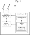
- Fig. 1 illustrates an example wireless access point ("AP") 100.
- the AP 100 may be any OFDMA capable communications device that is to act as an access point for a client device 200.
- the AP 100 may allow client devices 200 that are wirelessly connected thereto to communicate with one another and/or an external network (such as the network 300) via various communications standards.
- AP can refer to a networking device that allows a client device to connect to a wired or wireless network.
- the term AP can, for example, refer to receiving points for any wireless access technology which is now known or may later become known. Specifically, the term AP is not intended to be limited to IEEE 802.11-based APs.
- APs generally function as an electronic device that is adapted to allow wireless devices to connect to a wired network via various communication standards.
- An AP can include a processing resource, memory, and/or input/output interfaces, including wired network interfaces such as IEEE 802.3 Ethernet interfaces, as well as wireless network interfaces such as IEEE 802.11 Wi-Fi interfaces, although examples of the disclosure are not limited to such interfaces.
- An AP can include a memory resource, including read-write memory, and a hierarchy of persistent memory such as ROM, EPROM, and Flash memory.
- An AP may provide access to a wireless network, such as a Wireless Local Area Network (WLAN).
- WLAN can, for example, refer to a communications network that links two or more devices using some wireless distribution method (for example, spread-spectrum or orthogonal frequency-division multiplexing radio), and also usually providing a connection through an AP to the Internet.
- a WLAN may provide users with the mobility to move around within a local coverage area and still stay connected to the network.
- An AP may include one or a plurality of radios.
- a radio refers to hardware on an AP to receive signals and transmit the received signals to other components within the AP.
- the radio of an AP may receive signals from within the WLAN, such as wireless signals, or the radio may receive external signals, such as from sources outside the WLAN.
- the AP 100 may include wireless communications circuitry 110, control circuitry 120, and a network interface 130.
- the wireless communications circuitry 110 may wirelessly transmit messages to client devices, such as the client devices 200 illustrated in Fig. 2 .
- the wireless communications circuitry 110 may also receive messages wirelessly transmitted from the client devices 200.
- the network interface 130 may connect the AP 100 to a network, such as the network 300 illustrated in Fig. 2 .
- the control circuitry 120 may control the wireless communications circuitry 110.
- the control circuitry 120 may also control the network interface 130.
- all of the operations of the AP 100 may be controlled by the control circuitry 120 (e.g., the AP 100 may be a so-called "fat" AP). In other examples, some or all of the operations of the AP 100 may be controlled by an external controller 500 (described in the next section), and in some such examples, the control circuitry 120 may play a diminished role or be omitted entirely (e.g., the AP 100 may be a so-called "thin" AP). In other examples, the AP 100 may be a node of a distributed system, together with other APs, that forms a virtualized controller that controls some or all operations of each AP in the system.
- the wireless communications circuitry 110 includes P antennas 111 (111-1 through 111-P), where P is an integer equal to or greater than one.
- the antennas 111-1 through 111-P may transmit and/or receive signals in the form of electromagnetic radiation. Any portion of the electromagnetic spectrum may be used to transmit/receive messages.
- a transport protocol adopted by the AP 100 may specify a particular portion of the electromagnetic spectrum for transmission/reception (for example, IEEE 802.11ax specifies 2.4 Ghz and 5Ghz bands).
- the wireless communications circuitry 110 may include a wireless chipset.
- the wireless communications circuitry 110 may utilize OFDMA communication techniques to transmit and/or receive messages.
- the wireless communications circuitry 110 may utilize additional types of communication techniques, including, for example, multi-user-multiple-input-multiple-output (MU-MIMO), single-user MIMO (SU-MIMO), single-input-single-output (SISO), multiple-input-single-output (MISO), OFD single-access (OFDSA), etc.
- MU-MIMO multi-user-multiple-input-multiple-output
- SU-MIMO single-user MIMO
- SISO single-input-single-output
- MISO multiple-input-single-output
- OFDSA OFD single-access
- a transmission mode may be selected depending on a type of communication technology that a target client device 200 is capable of using.
- the AP 100 may be able to operate using any of the aforementioned techniques or combinations thereof (or using techniques not specifically mentioned), operations described herein
- the wireless communications circuitry 110 may utilize OFDMA techniques to transmit multiple data signals concurrently (e.g., in a same transmission frame) via multiple orthogonal frequency sub-bands (subcarriers) of the wireless channel, respectively.
- the concurrently sent data signals may be destined for multiple client devices 200.
- the wireless communications circuitry 110 may also combine the OFDMA techniques with any of the MU-MIMO, SU-MIMO, SISO, and MISO techniques.
- the wireless communications circuitry 110 may generate data streams for transmission by packaging messages that are to be transmitted into transmission frames (e.g., MAC and PHY framing) according to the wireless transmission protocol adopted by the AP 100, mapping the transmission frames to transmission symbols according to a modulation scheme and modulating a carrier signal based on the transmission symbols, and wirelessly transmitting the modulated signals via amplifiers and the antennas 111-1 through 111-P.
- transmission frames e.g., MAC and PHY framing
- Examples of wireless transmission protocols include IEEE 802.11, IEEE 802.16, 3GPP E-UTRA, and the like.
- modulation schemes include quadrature amplitude modulation (QAM), phase-shift keying (PSK), frequency-shift keying (FSK), amplitude-shift keying (ASK), frequency-division multiplexing (FDM), orthogonal frequency-division multiplexing (OFDM), continuous phase modulation (CPM), and the like.
- QAM quadrature amplitude modulation
- PSK phase-shift keying
- FSK frequency-shift keying
- ASK amplitude-shift keying
- FDM frequency-division multiplexing
- OFDM orthogonal frequency-division multiplexing
- CPM continuous phase modulation
- Some wireless transmission protocols specify use of a particular modulation scheme; for example, IEEE 802.11ax specifies use of QAM modulation.
- the wireless communications circuitry 110 may include circuitry for generating the carrier signal such as an oscillator, a modulator for modulating the carrier signal, filters, amplifiers, and the like.
- the wireless communications circuitry 110 may also include precoding
- the wireless communications circuitry 110 may also receive wireless transmissions from client devices via the antennas 111-1 through 111-P, and may demodulate the received signals via demodulation circuitry to obtain reception frames.
- the wireless communications circuitry 110 may receive MU-MIMO, SU-MIMO, SISO, MISO, OFDMA, and/or OFDSA communications.
- Reception frames whose respective payloads are intended to go to the network 300 e.g., data plane messages
- reception frames that include control plane messages may be sent to the control circuitry 120 for processing.
- the wireless communications circuitry 110 may also generate FFT bin data for use by the control circuitry 120. For example, many commercially available wireless chipsets are able to generate such FFT bin data, and in some examples the wireless communications circuitry 110 may include such a wireless chipset. In examples in which the AP does not include a wireless chipset that generates such FFT bin data, the control circuitry 120 may determine the FFT bin data by periodically applying a FFT function to the received signals.
- the FFT bins may be identified by the wireless chipset as being protocol bins or non-protocol bins; for example, a 802.11 wireless chipset may identify whether the signal represented in each bin is a WiFi signal (protocol bin) or a non-WiFi signal (non-protocol bin).
- the control circuitry 120 may label the FFT bins as protocol or non-protocol bins; for example, bins that include signals that do not include identifying information specified by the relevant protocol may be labeled as non-protocol bins.
- the control circuitry 120 may be configured to perform the operations described herein in relation to allocating RUs to client devices 200. More specifically, the control circuitry 120 may be configured to perform the operations of Fig. 3 and/or 4. In addition, the control circuitry 120 may also control the operations of the wireless communications circuitry 110 and/or the network interface 130. The control circuitry 120 may also generate control plane messages to be sent to client devices 200 via the wireless communications circuitry 110, and may process control plane messages received from client devices 200.
- the control circuitry 120 includes processing circuitry 121, and, in some examples, storage 123.
- the processing circuitry 121 may include a number of processors (physical or virtual), dedicated hardware, or any combination of these.
- a "processor” may include (or be virtualized from) any circuitry that is capable of executing machine-readable instructions, such as central processing units (CPUs), microprocessors, microcontrollers, digital signal processors (DSPs), field-programmable gate arrays (FPGAs), application-specific instruction set processors (ASIPs), etc.
- the processing circuitry 121 includes processors
- the processors may be configured to perform operations described herein, such as some or all of the operations of Fig. 3 and/or 4, as a result of executing machine readable instructions, such as the channel access instructions 124.
- control circuitry 120 may also include the storage 123 (physical or virtual), which may store the machine-readable instructions that are executed by the processors.
- the processing circuitry 121 may include components that support the processors and/or provide additional functionality, such as caches, coprocessors, timing sources, etc.
- dedicated hardware may include any circuitry that is configured to perform operations described herein, such as some or all of the operations of Fig. 3 and/or 4.
- dedicated hardware may include application-specific integrated circuits (ASICs), complex programmable logic devices (CPLD), and so on.
- ASICs application-specific integrated circuits
- CPLD complex programmable logic devices
- processing circuitry 121 includes both processors and dedicated hardware, some or all of such additional hardware components may be integrated into a same integrated circuit as the processor.
- the processing circuitry 121 may be a system-on-chip (SoC).
- the control circuitry 120 includes the storage 123, which may store the RU allocation instructions 124.
- the storage 123 may include (or be virtualized form) any non-transitory machine readable medium, which may include volatile storage media (e.g., DRAM, SRAM, etc.) and/or non-volatile storage media (e.g., PROM, EPROM, EEPROM, NVRAM, flash, hard drives, optical disks, etc.).
- the RU allocation instructions 124 may include instructions to perform some or all of the operations illustrated in Figs. 3 and/or 4. In examples in which the processing circuitry 121 is constituted entirely by dedicated hardware, the storage 123 and the RU allocation instructions 124 may be omitted.
- the network interface 130 connects the AP 100 to a network, such as the network 300.
- the network interface 130 includes at least one communications port that is connectable to the network, and may pass data between the wireless communications circuitry 110 and the network via the communications port.
- the network interface 130 may act as a hub, a bridge, a switch, a router, etc.
- wireless communications circuitry 110 While the wireless communications circuitry 110, the control circuitry 120, and the network interface 130 are illustrated and described separately herein, this is merely for ease of explanation and does not imply that these components are necessarily physically or logically separated.
- the wireless communications circuitry 110 and the control circuitry 120 may share one or more of the same processors and/or ASICs, such as a wireless transceiver chipset, and they may overlap with one another physically and/or functionally.
- a particular operation may appropriately be described as being performed simultaneously by both the wireless communications circuitry 110 and the control circuitry 120, since the control circuitry 120 may control the wireless communications circuitry 110.
- the wireless communications circuitry 110 may be said to modulate a carrier signal because it physically alters a parameter of the carrier signal, but the control circuitry 120 may also be said to modulate the carrier signal because it controls the wireless communications circuitry 110 in the modulation.
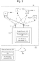
- Fig. 2 illustrates an example system 10.
- the example system 10 includes an AP 100, client devices 200 (e.g., client devices 200_1-200_4), and an external network 300.
- client devices 200 e.g., client devices 200_1-200_4
- the system 10 may also include an external controller 500 that is communicably connected to the AP 100.
- the AP 100 wirelessly communicates with the client devices 200, and may provide a connection between the client devices 200 and other computing devices via the external network 300.
- the control circuitry 120 of the AP 100 may fully control the RU allocation processes described herein.
- an external controller 500 may be included that controls some or all of the RU allocation processes described herein.
- the AP 100 may be a node of a distributed system, together with other APs, that forms a virtualized controller that controls some or all of the RU allocation processes described herein.
- the client devices 200 may be any electronic devices that are capable of wirelessly communicating with the AP 100 via any communications protocol.
- the client devices 200 may include mobile phones, tablets, laptop computers, personal-digital-assistants (PDAs), smart devices (e.g., smartphones, tablets, smart watches, smart bands, smart glasses, etc.), Bluetooth devices, internet-of-things (loT) embedded devices, networking devices (e.g., wireless extenders, wireless bridges, etc.), and so on.
- PDAs personal-digital-assistants
- smart devices e.g., smartphones, tablets, smart watches, smart bands, smart glasses, etc.
- Bluetooth devices e.g., iPads, Samsung Galaxy Tabs, etc.
- ITT internet-of-things
- networking devices e.g., wireless extenders, wireless bridges, etc.
- the network 300 may be any wired or wireless network, such as, for example, a local area network (LAN), a wide area network (WAN), the internet, a telecommunications backhaul network (such as the Evolved Universal Mobile Telecommunications System Terrestrial Radio Access Network (E-UTRAN) portion of an LTE network), a telecommunications core network (such as the Evolved Packet Core portion of an LTE network), and so on.
- the AP 100 and client devices 200 that are connected thereto may be referred to herein collectively as a wireless network 400.
- the external controller 500 may be an on-premises appliance (not illustrated) that is connected to and controls a collection of APs, including the AP 100.
- the external controller 500 may be connected between the AP 100 and the external network 300, such that data communications between the AP 100 and external network 300 pass through the external controller 500.
- Examples of such external controllers 500 include so-called WLAN Controllers and AP Controllers.
- the external controller 500 may be an off-premises appliance that is connected to the APs via the network 300 (e.g., via the internet).
- the external controller 500 may be a cloud appliance, which may be operated, for example, by a third party (e.g., a cloud service provider, the vendor of the AP 100, etc.).
- an external controller 500 may include processing circuitry 521 that is configured to perform some or all of the RU allocation operations described herein.
- the external controller 500 may include the RU allocation instructions 124, which when executed by a processor (physical or virtualized) of the external controller 500, cause it to perform the RU allocation operations.
- the wireless communication circuitry 110 of the AP 100 may provide the FFT bins to the external controller 500, and then the external controller 500 may analyze the FFT bins (e.g., identify the groupings), identify the RUs to skip, and cause the AP 100 to skip the identified RUs.
- the external controller 500 may analyze the FFT bins (e.g., identify the groupings), identify the RUs to skip, and cause the AP 100 to skip the identified RUs.
- control circuitry 120 of the AP 100 may still participate in some aspects of the RU allocation for example, the external controller 500 may simply instruct the AP 100 which RUs to skip, and the control circuitry 120 may then decide on its own how to allocate the non-skipped RUs. In other examples, the external controller 500 may control every aspect of the RU allocation.
- the control circuitry 120 of the AP 10 may be greatly diminished or even omitted entirely.
- the AP 100 may be a so-called "thin" AP.
- the AP 100 may be a node of a distributed system, together with other APs.
- the distributed system may form a virtualized controller that controls all of the APs that are members of the distributed system.
- control plane operations may be distributed across the processing circuitry of multiple APs, rather than each AP controlling just itself.
- some or all of the RU allocation processes described herein may be performed by the virtual controller. More specifically, one, some, or all of the APs in the system may include the RU allocation instructions 124.
- the wireless communication circuitry 110 of the AP 100 may provide the FFT bins to the virtual controller, and then the virtual controller may analyze the FFT bins (e.g., identify the groupings), identify the RUs to skip, and cause the AP 100 to skip the identified RUs.
- Fig. 3 illustrates an example process 1000 of allocating RUs to client devices as part of an OFDMA communication.
- the example process 1000 may be performed by control circuitry of an AP (such as the control circuitry 120 described above).
- the example process 1000 may also be performed by an external controller that controls an AP (such as the external controller 500 described above).
- the example process 1000 may also be performed by a virtual controller that controls an AP.
- one or more processors included in the AP, an external controller, and/or another AP may perform the process 1000 as a result of executing machine readable instructions corresponding to the operations described below (such as the RU allocation instructions 124).
- the entity that performs the process 1000 will be referred to below generically as a "controller", which should be understood broadly to include the control circuitry of an AP, an external controller, and/or a virtual controller.
- Fig. 5 is a graph illustrating hypothetical FFT bin data, with bin numbers on the horizontal axis and signal strength on the vertical axis.
- a signal strength threshold T (“first threshold") is indicated by a dashed line, and those FFT bins whose signal strength exceeds T are indicated with hatching.
- the controller may identify groupings of contiguous FFT bins in which: 1) all of the bins are non-protocol FFT bins, 2) all of the bins have signal strength values exceeding a first threshold ("T"); and 3) the bandwidth of the grouping does not exceed a second threshold ("B").
- Such identified groupings may be considered as instances of narrowband interference.
- Contiguous in this context means that there are not any FFT bins that are not members of the grouping located between any FFT bins in the grouping.
- groupings that satisfy the first and second criteria noted above: [2, 3], [6, 7, 8, 9], [16, 17], and [19]. These groupings are indicated in Fig. 5 as groupings A-D.
- grouping [16, 17, 19] is not a grouping of contiguous bins, because bin 18, which is located between bins 17 and 19, is not included in the proposed grouping.
- the bandwidth of a grouping of FFT bins may be the difference between the frequency associated with the highest bin upper boundary and the frequency associated with the lowest bin lower boundary in the grouping.
- the subsumed grouping(s) may be ignored and the larger grouping may be the one that is considered for compliance with the third criteria. For example, in Fig.
- each of the groupings [6, 7], [7, 8], [8, 9], [6, 7, 8], and [7, 8, 9] satisfy the first and second criteria noted above, all of these are wholly subsumed by the larger grouping [6, 7, 8, 9]; accordingly, in determining compliance with the third criteria, the AP may consider the grouping [6, 7, 8, 9] and ignore the subsumed groupings [6, 7], [7, 8], [8, 9], [6, 7, 8], and [7, 8, 9].
- neither the grouping [6, 7, 8, 9] nor any of its subsumed groupings would be identified in block 1001, since their bandwidth exceeds B.
- the third criterion noted above is intended to distinguish narrowband interference sources from broadband interference sources.
- groupings of contiguous non-protocol FFT bins that satisfy the first and second criteria but do not satisfy the third criteria may be considered as broadband interference.
- broadband interference is not the subject of the present disclosure.
- broadband interference groupings are not identified in block 1001 for use in the subsequent operations of Fig. 3 ; however, this does not preclude the AP from identifying such broadband interference groupings for other purposes, such as for use in a broadband interference mitigation process.
- the controller may consider a particular RU and determine whether the RU overlaps with any of the groupings that were identified in block 1001. If the RU overlaps with any of the groupings, then the process continues to block 1003, in which the RU is removed from a pool of available RUs. If the RU does not overlap with any of the groupings, then to process continues to block 1004.
- the controller may determine that a given RU overlaps a given grouping if either the lowest frequency ( group_start ) or the highest frequency ( group_end ) associated with the grouping is located between the lowest frequency (RU_start) and the highest frequency (RU_end) of the RU. In other words, if either RU_start ⁇ group_start ⁇ RU_end or RU_start ⁇ group_end ⁇ RU_end, then the RU overlaps the group.
- the frequencies associated with the boundaries of the FFT bins are not necessarily specified in the FFT bin data output by the radio chip, in which case the controller may infer these frequencies from other information in order to perform the determination of block 1002.
- process 1000 continues to block 1003; otherwise, process 1000 continues to block 1004.
- the RU is removed from a pool of available RUs. When RU's are ultimately assigned to client devices, only RU's that are still included in the pool are available to be assigned. Thus, removing an RU from the pool is equivalent to "skipping" the RU during allocation. After block 1003, the process continues to block 1004.
- the controller may determine whether all of the RUs have been considered. If so, the process continues to block 1006. If not the process loops back to block 1002, via block 1005, to consider a next RU.
- RUs are assigned to client devices from the pool of available RUs. Specifically, only RUs that remain in the pool may be assigned to client devices. Any allocation algorithm may be used in block 1006 to assign the RUs to the client devices, as long as the algorithm skips the RUs that have been removed from the pool. The process then ends.
- some or all of the operations of Fig. 3 may be performed each time that RUs are to be allocated to client devices. For example, the entire process of Fig. 3 may be performed each time that an OFDMA communication is to be sent or received by the AP. As another example, the allocation of RUs to client devices (block 1006) may be performed every time that RUs are to be allocated, but other operations may be performed at different timings.
- Fig. 3 may be performed periodically at set intervals.
- the identifying of FFT bin groupings (block 1001) and/or the identification of RUs that overlap the identified grouping (block 1002) may be performed periodically at set time intervals.
- Fig. 4 illustrates one example of how the sub-process 1001 from Fig. 3 may be implemented.
- the FFT bins are considered sequentially in turn, starting with the lowest FFT bin and working upward or starting with the highest FFT bin and working downward.
- a particular FFT bin is considered, and the controller determines whether the bin is a non-protocol FFT bin. If so, the process continues to block 1012. If not, the process continues to block 1014.
- non-protocol FFT bins and the protocol FFT bins may already have been sorted prior to the process 1000, and the process 1000 may consider only non-protocol FFT bins.
- block 1011 will always be answered "yes", and therefore the controller does not need to make an explicit determination or perform operations associated with such a determination when block 1011 is reached.
- the operations associated with block 1011 may be omitted, and instead the process may simply proceed from block 1011 directly to block 1012.
- the controller determines whether the signal strength of the FFT bin exceeds the threshold T. If so, the process continues to block 1013. If not the process continues to block 1014.
- block 1013 the controller flags the FFT bin. Note that block 1013 is reached only if the FFT bin is a non-protocol FFT bin and has a signal strength exceeding T. After block 1013, the process continues to block 1018.
- the controller determines whether the previous FFT bin has been flagged. If not, then the process continues to block 1018. If so, then the process continues to block 1015.
- the controller identifies all of the currently flagged FFT bins as a grouping that satisfies the criteria noted above in relation to block 1001 of Fig. 3 . The process then continues to block 1017.
- the controller clears the flags from the FFT bins. The process then continues to block 1018.
- the controller may determine whether all of the FFT bins have been considered. If so, the process ends. If not the process loops back to block 1011, via block 1019, to consider a next FFT bin.
- Fig. 6 illustrates an example non-transitory machine readable medium 4000 that stores RU allocation instructions 124.
- the machine readable medium 4000 may include any non-transitory media that can store instructions and is readable by a machine, such as a memory device (e.g., RAM, persistent memory, USB drive, etc.), a hard disk drive, a solid-state drive, an optical disk (e.g., CD, DVD, Blu-ray, etc.), a magnetic disk, and the like.
- a memory device e.g., RAM, persistent memory, USB drive, etc.
- a hard disk drive e.g., a hard disk drive
- a solid-state drive e.g., an optical disk (e.g., CD, DVD, Blu-ray, etc.), a magnetic disk, and the like.
- an optical disk e.g., CD, DVD, Blu-ray, etc.
- the RU allocation instructions 124 may include instructions that are of such a nature that, when they are executed by processing circuitry of a controller that controls an AP, they cause the processing circuitry to perform the operations described above in relation to Figs. 3 and/or 4.
- the RU allocation instructions 124 may include FFT bin grouping instructions 4011 and overlap determination and RU skipping instructions 4012.
- the controller whose processing circuitry executes the RU allocation instructions 124 may be the control circuitry of the individual AP (such as the control circuitry 120 described above), a controller external to the AP (such as the external controller 500 described above), or a virtual controller formed by a distributed system of APs.
- the FFT bin grouping instructions 4011 may include instructions to identify groupings of contiguous FFT bins in which: 1) all of the bins are non-protocol FFT bins, 2) all of the bins have signal strength values exceeding a first threshold ("T"); and 3) the bandwidth of the grouping does not exceed a second threshold ("B").
- the FFT bin grouping instructions 4011 may include instructions to the operations described above in relation to block 1001 of Fig. 3 .
- the FFT bin grouping instructions may include instructions to perform the operations described above in relation to Fig. 4 .
- the overlap determination and RU skipping instructions 4012 may include instructions to determine whether any RUs overlap any of the groupings identified by the FFT bin grouping instructions 4011.
- the overlap determination and RU skipping instructions 4012 may also include instructions to skip any such RUs when allocating RUs to client devices.
- the overlap determination and RU skipping instructions 4012 may include operations corresponding to blocks 1002 through 1006 of Fig. 3 .
- Some of the electronic devices described above may include some components that may be physical or virtualized, such as a processor of the processing circuitry 121, the storage 123, etc.
- a processor of the processing circuitry 121 may be physical or virtualized
- the component(s) may be physical or virtualized. Accordingly, any references herein and in the appended claims to any components of a device that do not specify "physical” or “virtual” should be understood to admit both physical and virtualized types of the components (in any combination). However, any virtualized component of a device is necessarily virtualized from underlying physical hardware.
- a given component of a device necessarily implies the presence somewhere in the system of physical hardware corresponding to the given component, with the given component either being one-and-the-same as the corresponding physical hardware or being virtualized from the corresponding physical hardware. Note that there is not necessarily a one-to-one ratio between physical hardware and the virtual components virtualized therefrom (one virtual component may span multiple physical components or multiple virtual components may share one physical component).
- a "processor” may include any logic circuitry that is capable of executing machine readable instructions stored in a non-transitory machine-readable medium (such as the storage 123, an optical disk, a magnetic disk, etc).
- a "processor” (such as a processor of the processing circuitry 121) may be, for example, a central processing unit (CPU), a microprocessor, a microcontroller, a digital signal processor (DSP), etc.
- a "coprocessor” is a processor that is configured to supplement the functions of a primary processor.
- a coprocessor may be controlled by coprocessor instructions that are part of a primary processor's instruction stream.
- a coprocessor may be independent of and capable of working asynchronously with the primary processor.
- phrase "and/or” is used herein in conjunction with a list of items. This phrase means that any combination of items in the list-from a single item to all of the items and any permutation in between-may be included.
- “A, B, and/or C” means "one of ⁇ A ⁇ , ⁇ B ⁇ , ⁇ C ⁇ , ⁇ A, B ⁇ , ⁇ A, C ⁇ , ⁇ C, B ⁇ , and ⁇ A, C, B ⁇ ".
Landscapes
- Engineering & Computer Science (AREA)
- Signal Processing (AREA)
- Computer Networks & Wireless Communication (AREA)
- Quality & Reliability (AREA)
- Mobile Radio Communication Systems (AREA)
- Physics & Mathematics (AREA)
- Electromagnetism (AREA)
Abstract
Description
- A wireless channel may be used for conveying wireless communications between an access point and client devices. Various wireless communications techniques may be used to increase the number of distinct data signals that may be concurrently carried on the wireless channel between the access point and client devices. For example, orthogonal-frequency-division (OFD) techniques may divide an available system bandwidth into multiple orthogonal frequency sub-bands (aka subcarriers) and concurrently transmit multiple distinct data signals via the frequency sub-bands, respectively.
-
-
Fig. 1 is a block diagram illustrating an example wireless access point. -
Fig. 2 is a block diagram illustrating an example system that includes an example wireless network with an example wireless access point and example client devices. -
Fig. 3 is a process flow diagram illustrating an example process for allocating resource units to client devices. -
Fig. 4 is a process flow diagram illustrating an example sub-process for identifying groupings as part of the example process ofFig. 3 . -
Fig. 5 is a graph illustrating hypothetical FFT bin data, with bin numbers on a horizontal axis and signal strength on a vertical axis. -
Fig.6 is a block diagram illustrating an example non-transitory machine readable medium storing example resource unit allocation instructions. - One type of OFD technique is orthogonal-frequency-division multiple access (OFDMA), in which data signals that are associated with different users may be transmitted simultaneously on the same wireless channel by assigning them to different subcarriers. In particular, for each OFDMA downlink data transmission frame, a wireless access point ("AP") may assign subcarriers of the wireless channel to one or more users, and may transmit data streams to those users using their respectively assigned subcarriers. Similarly, in some examples, for each OFDMA uplink data transmission frame, the AP may assign subcarriers of the wireless channel to one or more users, and may instruct the selected users to transmit their data streams using their respectively assigned subcarriers. The AP may use any algorithm to select the users that are to receive or transmit, and may use any algorithm to allocate the subcarriers amongst the selected users. The numbers and identities of users that are selected to receive transmission may vary from frame to frame, the subcarriers that are allocated to a given user may vary from frame to frame, and users do not necessarily have equal allocations of subcarriers in each frame or even in the long run.
- In some OFDMA implementations, such as for example in 802.11ax wireless access points, a wireless channel may be divided into non-overlapping groups of subcarriers called resource units ("RU"), where each RU includes a predefined number of subcarriers. In these examples, subcarriers are assigned to users in units of RUs, i.e., if a user is assigned an RU, it is assigned all of the subcarriers in the RU.
- In examples described herein, an AP may monitor the wireless channel in real time to detect narrow band interference, and when an AP is assigning RUs to users the AP may skip (i.e., not assign to any user) any RU if that RU contains such narrow band interference. Although skipping such an RU may reduce the number of subcarriers that are usable in a given frame, it can nonetheless improve the overall throughput (i.e., amount of data that is successfully communicated per unit time) in the long run. In particular, when an RU that includes some narrowband interference is used for transmissions, some of those transmissions may fail, which may result in the transmission needing to be re-sent. In some cases, the entire frame may need to be re-sent, even if the interference affects only some of the subcarriers. Such frame retries may be extremely costly in terms of throughput. By skipping the RUs with narrowband interference, such frame retries may be avoided, thus increasing throughput.
- More specifically, example APs described herein may detect narrow band interference by monitoring and analyzing Fast-Fourier-Transform (FFT) bin data, which may be provided, for example, by a radio chip of the AP. In particular, in examples described herein, narrow band interference may be defined as any grouping of one or more contiguous non-protocol FFT bins in which (A) all of the non-protocol FFT bins in the grouping have respective signal strength values exceeding a first threshold, and (B) a bandwidth of the grouping does not exceed a second threshold. Thus, the example APs may periodically identify any RUs that overlap with such a grouping of contiguous non-protocol FFT bins that satisfy the criteria noted above, and the AP may skip the identified RUs when allocating the RUs to client devices for an OFDMA communication. The AP may determine whether an RU overlaps with a grouping of bins by determining whether a start frequency or an end frequency of the grouping is between a start frequency and an end frequency of the RU.
- As used herein, protocol FFT bins are those that contain signals that utilize one of a number of specified protocols, while non-protocol FFT bins are those that contain signals that do not use one of the specified protocols. The specified protocols may include, for example, the specific protocol that the AP is designed to use, as well as other protocols that are compatible with the protocol used by the AP. For example, in an 802.11ax AP, the protocol FFT bins may be those that contain WiFi signals (i.e., signals that comply with one of the 802.11 family of protocols), while the non-protocol FFT bins may be those that contain non-WiFi signals. As another example, in a Long-Term Evolution (LTE) AP (aka an EnodeB), the protocol FFT bins may be those that contain LTE signals (i.e., signals that use, or are compatible with, the Evolved Universal Terrestrial Radio Access (E-UTRA) protocol), while the non-protocol FFT bins may be those that contain non-LTE signals.
- Below, examples will be described from the perspective of downlink transmissions from an AP to client devices, for ease of description. However, it should be understood that, in some examples, uplink transmissions from client devices to an AP may also be subject to the operations described herein. In particular, whether the transmissions are downlink or uplink, the AP will still control which users will be allocated which RUs for OFDMA data frames.
-
Fig. 1 illustrates an example wireless access point ("AP") 100. The AP 100 may be any OFDMA capable communications device that is to act as an access point for aclient device 200. Specifically, the AP 100 may allowclient devices 200 that are wirelessly connected thereto to communicate with one another and/or an external network (such as the network 300) via various communications standards. - As used herein, "access point" (AP) can refer to a networking device that allows a client device to connect to a wired or wireless network. The term AP can, for example, refer to receiving points for any wireless access technology which is now known or may later become known. Specifically, the term AP is not intended to be limited to IEEE 802.11-based APs. APs generally function as an electronic device that is adapted to allow wireless devices to connect to a wired network via various communication standards. An AP can include a processing resource, memory, and/or input/output interfaces, including wired network interfaces such as IEEE 802.3 Ethernet interfaces, as well as wireless network interfaces such as IEEE 802.11 Wi-Fi interfaces, although examples of the disclosure are not limited to such interfaces. An AP can include a memory resource, including read-write memory, and a hierarchy of persistent memory such as ROM, EPROM, and Flash memory.
- An AP may provide access to a wireless network, such as a Wireless Local Area Network (WLAN). As used herein, a WLAN can, for example, refer to a communications network that links two or more devices using some wireless distribution method (for example, spread-spectrum or orthogonal frequency-division multiplexing radio), and also usually providing a connection through an AP to the Internet. Thus, a WLAN may provide users with the mobility to move around within a local coverage area and still stay connected to the network.
- An AP may include one or a plurality of radios. As used herein, a radio refers to hardware on an AP to receive signals and transmit the received signals to other components within the AP. The radio of an AP may receive signals from within the WLAN, such as wireless signals, or the radio may receive external signals, such as from sources outside the WLAN.
- The AP 100 may include
wireless communications circuitry 110,control circuitry 120, and anetwork interface 130. Thewireless communications circuitry 110 may wirelessly transmit messages to client devices, such as theclient devices 200 illustrated inFig. 2 . Thewireless communications circuitry 110 may also receive messages wirelessly transmitted from theclient devices 200. Thenetwork interface 130 may connect the AP 100 to a network, such as thenetwork 300 illustrated inFig. 2 . Thecontrol circuitry 120 may control thewireless communications circuitry 110. Thecontrol circuitry 120 may also control thenetwork interface 130. - In some examples, all of the operations of the AP 100 may be controlled by the control circuitry 120 (e.g., the AP 100 may be a so-called "fat" AP). In other examples, some or all of the operations of the AP 100 may be controlled by an external controller 500 (described in the next section), and in some such examples, the
control circuitry 120 may play a diminished role or be omitted entirely (e.g., the AP 100 may be a so-called "thin" AP). In other examples, the AP 100 may be a node of a distributed system, together with other APs, that forms a virtualized controller that controls some or all operations of each AP in the system. In the remainder of this section, it will be assumed for the sake of convenience that all of the operations of theAP 100 are controlled by itsown control circuitry 120; however, it should be understood that in practice some or all of the operations could be performed by other entities (such as an external controller or other AP in a distributed control system). - The
wireless communications circuitry 110 includes P antennas 111 (111-1 through 111-P), where P is an integer equal to or greater than one. The antennas 111-1 through 111-P may transmit and/or receive signals in the form of electromagnetic radiation. Any portion of the electromagnetic spectrum may be used to transmit/receive messages. A transport protocol adopted by theAP 100 may specify a particular portion of the electromagnetic spectrum for transmission/reception (for example, IEEE 802.11ax specifies 2.4 Ghz and 5Ghz bands). Thewireless communications circuitry 110 may include a wireless chipset. - The
wireless communications circuitry 110 may utilize OFDMA communication techniques to transmit and/or receive messages. In addition, thewireless communications circuitry 110 may utilize additional types of communication techniques, including, for example, multi-user-multiple-input-multiple-output (MU-MIMO), single-user MIMO (SU-MIMO), single-input-single-output (SISO), multiple-input-single-output (MISO), OFD single-access (OFDSA), etc. For example, a transmission mode may be selected depending on a type of communication technology that atarget client device 200 is capable of using. Although theAP 100 may be able to operate using any of the aforementioned techniques or combinations thereof (or using techniques not specifically mentioned), operations described herein chiefly pertain to communications that utilize OFDMA, and thus other modes of operation will not be described in greater detail herein. - More specifically, the
wireless communications circuitry 110 may utilize OFDMA techniques to transmit multiple data signals concurrently (e.g., in a same transmission frame) via multiple orthogonal frequency sub-bands (subcarriers) of the wireless channel, respectively. In addition, using OFDMA techniques, the concurrently sent data signals may be destined formultiple client devices 200. Thewireless communications circuitry 110 may also combine the OFDMA techniques with any of the MU-MIMO, SU-MIMO, SISO, and MISO techniques. - The
wireless communications circuitry 110 may generate data streams for transmission by packaging messages that are to be transmitted into transmission frames (e.g., MAC and PHY framing) according to the wireless transmission protocol adopted by theAP 100, mapping the transmission frames to transmission symbols according to a modulation scheme and modulating a carrier signal based on the transmission symbols, and wirelessly transmitting the modulated signals via amplifiers and the antennas 111-1 through 111-P. Examples of wireless transmission protocols include IEEE 802.11, IEEE 802.16, 3GPP E-UTRA, and the like. Examples of modulation schemes include quadrature amplitude modulation (QAM), phase-shift keying (PSK), frequency-shift keying (FSK), amplitude-shift keying (ASK), frequency-division multiplexing (FDM), orthogonal frequency-division multiplexing (OFDM), continuous phase modulation (CPM), and the like. Some wireless transmission protocols specify use of a particular modulation scheme; for example, IEEE 802.11ax specifies use of QAM modulation. Thewireless communications circuitry 110 may include circuitry for generating the carrier signal such as an oscillator, a modulator for modulating the carrier signal, filters, amplifiers, and the like. Thewireless communications circuitry 110 may also include precoding circuitry that applies weights to the P signals using beamforming techniques. The precoding weights may be determined by thecontrol circuitry 120. - The
wireless communications circuitry 110 may also receive wireless transmissions from client devices via the antennas 111-1 through 111-P, and may demodulate the received signals via demodulation circuitry to obtain reception frames. Thewireless communications circuitry 110 may receive MU-MIMO, SU-MIMO, SISO, MISO, OFDMA, and/or OFDSA communications. Reception frames whose respective payloads are intended to go to the network 300 (e.g., data plane messages) may be sent to thenetwork 300 via thenetwork interface 130, while reception frames that include control plane messages may be sent to thecontrol circuitry 120 for processing. - The
wireless communications circuitry 110 may also generate FFT bin data for use by thecontrol circuitry 120. For example, many commercially available wireless chipsets are able to generate such FFT bin data, and in some examples thewireless communications circuitry 110 may include such a wireless chipset. In examples in which the AP does not include a wireless chipset that generates such FFT bin data, thecontrol circuitry 120 may determine the FFT bin data by periodically applying a FFT function to the received signals. In some examples, the FFT bins may be identified by the wireless chipset as being protocol bins or non-protocol bins; for example, a 802.11 wireless chipset may identify whether the signal represented in each bin is a WiFi signal (protocol bin) or a non-WiFi signal (non-protocol bin). In other examples, thecontrol circuitry 120 may label the FFT bins as protocol or non-protocol bins; for example, bins that include signals that do not include identifying information specified by the relevant protocol may be labeled as non-protocol bins. - The
control circuitry 120 may be configured to perform the operations described herein in relation to allocating RUs toclient devices 200. More specifically, thecontrol circuitry 120 may be configured to perform the operations ofFig. 3 and/or 4. In addition, thecontrol circuitry 120 may also control the operations of thewireless communications circuitry 110 and/or thenetwork interface 130. Thecontrol circuitry 120 may also generate control plane messages to be sent toclient devices 200 via thewireless communications circuitry 110, and may process control plane messages received fromclient devices 200. - The
control circuitry 120 includesprocessing circuitry 121, and, in some examples,storage 123. Theprocessing circuitry 121 may include a number of processors (physical or virtual), dedicated hardware, or any combination of these. - As used herein, a "processor" may include (or be virtualized from) any circuitry that is capable of executing machine-readable instructions, such as central processing units (CPUs), microprocessors, microcontrollers, digital signal processors (DSPs), field-programmable gate arrays (FPGAs), application-specific instruction set processors (ASIPs), etc. In examples in which the
processing circuitry 121 includes processors, the processors may be configured to perform operations described herein, such as some or all of the operations ofFig. 3 and/or 4, as a result of executing machine readable instructions, such as thechannel access instructions 124. In examples in which theprocessing circuitry 121 includes processors, thecontrol circuitry 120 may also include the storage 123 (physical or virtual), which may store the machine-readable instructions that are executed by the processors. In addition, in examples in which theprocessing circuitry 121 includes processors, theprocessing circuitry 121 may include components that support the processors and/or provide additional functionality, such as caches, coprocessors, timing sources, etc. - In examples in which the
processing circuitry 121 includes dedicated hardware, such dedicated hardware may include any circuitry that is configured to perform operations described herein, such as some or all of the operations ofFig. 3 and/or 4. For example, dedicated hardware may include application-specific integrated circuits (ASICs), complex programmable logic devices (CPLD), and so on. - In some examples in which the
processing circuitry 121 includes both processors and dedicated hardware, some or all of such additional hardware components may be integrated into a same integrated circuit as the processor. In particular, in some such examples, theprocessing circuitry 121 may be a system-on-chip (SoC). - As noted above, in some examples the
control circuitry 120 includes thestorage 123, which may store theRU allocation instructions 124. Thestorage 123 may include (or be virtualized form) any non-transitory machine readable medium, which may include volatile storage media (e.g., DRAM, SRAM, etc.) and/or non-volatile storage media (e.g., PROM, EPROM, EEPROM, NVRAM, flash, hard drives, optical disks, etc.). TheRU allocation instructions 124 may include instructions to perform some or all of the operations illustrated inFigs. 3 and/or 4. In examples in which theprocessing circuitry 121 is constituted entirely by dedicated hardware, thestorage 123 and theRU allocation instructions 124 may be omitted. - The
network interface 130 connects theAP 100 to a network, such as thenetwork 300. Thenetwork interface 130 includes at least one communications port that is connectable to the network, and may pass data between thewireless communications circuitry 110 and the network via the communications port. Thenetwork interface 130 may act as a hub, a bridge, a switch, a router, etc. - While the
wireless communications circuitry 110, thecontrol circuitry 120, and thenetwork interface 130 are illustrated and described separately herein, this is merely for ease of explanation and does not imply that these components are necessarily physically or logically separated. For example, thewireless communications circuitry 110 and thecontrol circuitry 120 may share one or more of the same processors and/or ASICs, such as a wireless transceiver chipset, and they may overlap with one another physically and/or functionally. Moreover, a particular operation may appropriately be described as being performed simultaneously by both thewireless communications circuitry 110 and thecontrol circuitry 120, since thecontrol circuitry 120 may control thewireless communications circuitry 110. For example, thewireless communications circuitry 110 may be said to modulate a carrier signal because it physically alters a parameter of the carrier signal, but thecontrol circuitry 120 may also be said to modulate the carrier signal because it controls thewireless communications circuitry 110 in the modulation. -
Fig. 2 illustrates anexample system 10. Theexample system 10 includes anAP 100, client devices 200 (e.g., client devices 200_1-200_4), and anexternal network 300. In some examples, thesystem 10 may also include anexternal controller 500 that is communicably connected to theAP 100. - The
AP 100 wirelessly communicates with theclient devices 200, and may provide a connection between theclient devices 200 and other computing devices via theexternal network 300. In some examples, thecontrol circuitry 120 of theAP 100 may fully control the RU allocation processes described herein. However, in other examples, anexternal controller 500 may be included that controls some or all of the RU allocation processes described herein. In addition, in still further examples, theAP 100 may be a node of a distributed system, together with other APs, that forms a virtualized controller that controls some or all of the RU allocation processes described herein. - The
client devices 200 may be any electronic devices that are capable of wirelessly communicating with theAP 100 via any communications protocol. For example, theclient devices 200 may include mobile phones, tablets, laptop computers, personal-digital-assistants (PDAs), smart devices (e.g., smartphones, tablets, smart watches, smart bands, smart glasses, etc.), Bluetooth devices, internet-of-things (loT) embedded devices, networking devices (e.g., wireless extenders, wireless bridges, etc.), and so on. InFig. 2 , fourclient devices 200, labeled C1 through C4, are illustrated, but it should be understood that any number ofclient devices 200 may be connected to theAP 100. - The
network 300 may be any wired or wireless network, such as, for example, a local area network (LAN), a wide area network (WAN), the internet, a telecommunications backhaul network (such as the Evolved Universal Mobile Telecommunications System Terrestrial Radio Access Network (E-UTRAN) portion of an LTE network), a telecommunications core network (such as the Evolved Packet Core portion of an LTE network), and so on. TheAP 100 andclient devices 200 that are connected thereto may be referred to herein collectively as awireless network 400. - In some
example systems 10 that include anexternal controller 500, theexternal controller 500 may be an on-premises appliance (not illustrated) that is connected to and controls a collection of APs, including theAP 100. In some such examples, theexternal controller 500 may be connected between theAP 100 and theexternal network 300, such that data communications between theAP 100 andexternal network 300 pass through theexternal controller 500. Examples of suchexternal controllers 500 include so-called WLAN Controllers and AP Controllers. - In
other example systems 10 that include an external controller 500 (seeFig. 2 ), theexternal controller 500 may be an off-premises appliance that is connected to the APs via the network 300 (e.g., via the internet). For example, theexternal controller 500 may be a cloud appliance, which may be operated, for example, by a third party (e.g., a cloud service provider, the vendor of theAP 100, etc.). - In some examples in which an
external controller 500 is provided (regardless of whether it is on-premises (e.g., a WLAN Controller) or off-premises (e.g., a cloud appliance)), theexternal controller 500 may include processingcircuitry 521 that is configured to perform some or all of the RU allocation operations described herein. For example, theexternal controller 500 may include theRU allocation instructions 124, which when executed by a processor (physical or virtualized) of theexternal controller 500, cause it to perform the RU allocation operations. For example, thewireless communication circuitry 110 of theAP 100 may provide the FFT bins to theexternal controller 500, and then theexternal controller 500 may analyze the FFT bins (e.g., identify the groupings), identify the RUs to skip, and cause theAP 100 to skip the identified RUs. - In some examples, the
control circuitry 120 of theAP 100 may still participate in some aspects of the RU allocation for example, theexternal controller 500 may simply instruct theAP 100 which RUs to skip, and thecontrol circuitry 120 may then decide on its own how to allocate the non-skipped RUs. In other examples, theexternal controller 500 may control every aspect of the RU allocation. - In some examples, in which an
external controller 500 is provided, thecontrol circuitry 120 of theAP 10 may be greatly diminished or even omitted entirely. In such examples, theAP 100 may be a so-called "thin" AP. - As noted above, in some examples (not illustrated), the
AP 100 may be a node of a distributed system, together with other APs. The distributed system may form a virtualized controller that controls all of the APs that are members of the distributed system. Thus, in such examples, control plane operations may be distributed across the processing circuitry of multiple APs, rather than each AP controlling just itself. - In such examples, some or all of the RU allocation processes described herein may be performed by the virtual controller. More specifically, one, some, or all of the APs in the system may include the
RU allocation instructions 124. For example, thewireless communication circuitry 110 of theAP 100 may provide the FFT bins to the virtual controller, and then the virtual controller may analyze the FFT bins (e.g., identify the groupings), identify the RUs to skip, and cause theAP 100 to skip the identified RUs. -
Fig. 3 illustrates anexample process 1000 of allocating RUs to client devices as part of an OFDMA communication. Theexample process 1000 may be performed by control circuitry of an AP (such as thecontrol circuitry 120 described above). Theexample process 1000 may also be performed by an external controller that controls an AP (such as theexternal controller 500 described above). Theexample process 1000 may also be performed by a virtual controller that controls an AP. For example, one or more processors included in the AP, an external controller, and/or another AP, may perform theprocess 1000 as a result of executing machine readable instructions corresponding to the operations described below (such as the RU allocation instructions 124). The entity that performs theprocess 1000 will be referred to below generically as a "controller", which should be understood broadly to include the control circuitry of an AP, an external controller, and/or a virtual controller. - In describing the
process 1000 below, occasionally reference will be made toFig. 5 to illustrate certain points. As noted above,Fig. 5 is a graph illustrating hypothetical FFT bin data, with bin numbers on the horizontal axis and signal strength on the vertical axis. InFig. 5 , a signal strength threshold T ("first threshold") is indicated by a dashed line, and those FFT bins whose signal strength exceeds T are indicated with hatching. - Turning now to the
example process 1000, inblock 1001, the controller may identify groupings of contiguous FFT bins in which: 1) all of the bins are non-protocol FFT bins, 2) all of the bins have signal strength values exceeding a first threshold ("T"); and 3) the bandwidth of the grouping does not exceed a second threshold ("B"). Such identified groupings may be considered as instances of narrowband interference. - "Contiguous" in this context means that there are not any FFT bins that are not members of the grouping located between any FFT bins in the grouping. For example, from the hypothetical FFT bin data illustrated in
Fig. 5 , the following are groupings that satisfy the first and second criteria noted above: [2, 3], [6, 7, 8, 9], [16, 17], and [19]. These groupings are indicated inFig. 5 as groupings A-D. On the other hand, the grouping [16, 17, 19] is not a grouping of contiguous bins, becausebin 18, which is located betweenbins - The bandwidth of a grouping of FFT bins may be the difference between the frequency associated with the highest bin upper boundary and the frequency associated with the lowest bin lower boundary in the grouping. In some examples in which the FFT bins have uniform bin widths, the controller may determine the bandwidth of a grouping to be Gi = ni·w, where Gi is the bandwidth of the i th grouping, w is the bin width, and n i is the number of non-protocol FFT bins in the i th grouping. The controller may determine ni to be ni = Y - X + 1, where Y is a bin number of a highest bin in the grouping and X is a bin number of a lowest bin in the grouping. The controller may determine the bin width w i to be wi = W/N, where W is the bandwidth of the entire channel and N is the number of bins in the FFT bin data for the channel.
- In cases in which a grouping of contiguous FFT bins that satisfy the first and second criteria is wholly subsumed by another grouping of contiguous FFT bins that satisfy the first and second criteria, the subsumed grouping(s) may be ignored and the larger grouping may be the one that is considered for compliance with the third criteria. For example, in
Fig. 5 , although each of the groupings [6, 7], [7, 8], [8, 9], [6, 7, 8], and [7, 8, 9] satisfy the first and second criteria noted above, all of these are wholly subsumed by the larger grouping [6, 7, 8, 9]; accordingly, in determining compliance with the third criteria, the AP may consider the grouping [6, 7, 8, 9] and ignore the subsumed groupings [6, 7], [7, 8], [8, 9], [6, 7, 8], and [7, 8, 9]. Thus, for example, if the second threshold B were equal to three bin widths (B = 3w), then neither the grouping [6, 7, 8, 9] nor any of its subsumed groupings would be identified inblock 1001, since their bandwidth exceeds B. - The third criterion noted above is intended to distinguish narrowband interference sources from broadband interference sources. In particular, groupings of contiguous non-protocol FFT bins that satisfy the first and second criteria but do not satisfy the third criteria may be considered as broadband interference. However, such broadband interference is not the subject of the present disclosure. Thus, broadband interference groupings are not identified in
block 1001 for use in the subsequent operations ofFig. 3 ; however, this does not preclude the AP from identifying such broadband interference groupings for other purposes, such as for use in a broadband interference mitigation process. - In
block 1002, the controller may consider a particular RU and determine whether the RU overlaps with any of the groupings that were identified inblock 1001. If the RU overlaps with any of the groupings, then the process continues to block 1003, in which the RU is removed from a pool of available RUs. If the RU does not overlap with any of the groupings, then to process continues to block 1004. - In the determination of
block 1002, the controller may determine that a given RU overlaps a given grouping if either the lowest frequency (group_start) or the highest frequency (group_end) associated with the grouping is located between the lowest frequency (RU_start) and the highest frequency (RU_end) of the RU. In other words, if either RU_start ≤ group_start ≤ RU_end or RU_start ≤ group_end ≤ RU_end, then the RU overlaps the group. - In some examples, the frequencies associated with the boundaries of the FFT bins are not necessarily specified in the FFT bin data output by the radio chip, in which case the controller may infer these frequencies from other information in order to perform the determination of
block 1002. For example, the controller may determine the lowest frequency associated with an ith grouping (groupi_start) to be

Equations - As noted above, if the RU overlaps with any of the identified groups, then
process 1000 continues to block 1003; otherwise,process 1000 continues to block 1004. Inblock 1003, the RU is removed from a pool of available RUs. When RU's are ultimately assigned to client devices, only RU's that are still included in the pool are available to be assigned. Thus, removing an RU from the pool is equivalent to "skipping" the RU during allocation. Afterblock 1003, the process continues to block 1004. - In
block 1004, the controller may determine whether all of the RUs have been considered. If so, the process continues to block 1006. If not the process loops back to block 1002, viablock 1005, to consider a next RU. - In
block 1006, RUs are assigned to client devices from the pool of available RUs. Specifically, only RUs that remain in the pool may be assigned to client devices. Any allocation algorithm may be used inblock 1006 to assign the RUs to the client devices, as long as the algorithm skips the RUs that have been removed from the pool. The process then ends. - In some examples, some or all of the operations of
Fig. 3 may be performed each time that RUs are to be allocated to client devices. For example, the entire process ofFig. 3 may be performed each time that an OFDMA communication is to be sent or received by the AP. As another example, the allocation of RUs to client devices (block 1006) may be performed every time that RUs are to be allocated, but other operations may be performed at different timings. - For example, some operations of
Fig. 3 may be performed periodically at set intervals. For example, the identifying of FFT bin groupings (block 1001) and/or the identification of RUs that overlap the identified grouping (block 1002) may be performed periodically at set time intervals. -
Fig. 4 illustrates one example of how the sub-process 1001 fromFig. 3 may be implemented. In the sub-process 1001, the FFT bins are considered sequentially in turn, starting with the lowest FFT bin and working upward or starting with the highest FFT bin and working downward. - In
block 1011, a particular FFT bin is considered, and the controller determines whether the bin is a non-protocol FFT bin. If so, the process continues to block 1012. If not, the process continues to block 1014. - In some examples, the non-protocol FFT bins and the protocol FFT bins may already have been sorted prior to the
process 1000, and theprocess 1000 may consider only non-protocol FFT bins. In such examples,block 1011 will always be answered "yes", and therefore the controller does not need to make an explicit determination or perform operations associated with such a determination whenblock 1011 is reached. In other words, in such examples, the operations associated withblock 1011 may be omitted, and instead the process may simply proceed fromblock 1011 directly to block 1012. - In
block 1012, the controller determines whether the signal strength of the FFT bin exceeds the threshold T. If so, the process continues to block 1013. If not the process continues to block 1014. - In
block 1013, the controller flags the FFT bin. Note thatblock 1013 is reached only if the FFT bin is a non-protocol FFT bin and has a signal strength exceeding T. Afterblock 1013, the process continues to block 1018. - In
block 1014, the controller determines whether the previous FFT bin has been flagged. If not, then the process continues to block 1018. If so, then the process continues to block 1015. - In
block 1015, the controller determines whether the number of currently flagged FFT bins is less than or equal to a threshold b, where b = B/w. If so, then the process continues to block 1016. If not, then the process continues to block 1017. - In
block 1016, the controller identifies all of the currently flagged FFT bins as a grouping that satisfies the criteria noted above in relation to block 1001 ofFig. 3 . The process then continues to block 1017. - In block 1017, the controller clears the flags from the FFT bins. The process then continues to block 1018.
- In
block 1018, the controller may determine whether all of the FFT bins have been considered. If so, the process ends. If not the process loops back to block 1011, viablock 1019, to consider a next FFT bin. - The process flow diagrams in
Figs. 3 and4 and the descriptions herein are presented to aid the understanding of the example processes, but are not intended to be exhaustive descriptions thereof. For example, the example processes could include additional operations besides those illustrated in the Figures and described herein. As another example, the example processes could omit certain operations illustrated in the Figures and described herein. Furthermore, the operations are illustrated in a particular order for ease of description, but in practice some operations may be performed concurrently and/or in a different order than that illustrated. In addition, certain operations that were described separately for ease of understanding may, in practice, be performed together as part of a single operation. -
Fig. 6 illustrates an example non-transitory machine readable medium 4000 that storesRU allocation instructions 124. The machine readable medium 4000 may include any non-transitory media that can store instructions and is readable by a machine, such as a memory device (e.g., RAM, persistent memory, USB drive, etc.), a hard disk drive, a solid-state drive, an optical disk (e.g., CD, DVD, Blu-ray, etc.), a magnetic disk, and the like. - The
RU allocation instructions 124 may include instructions that are of such a nature that, when they are executed by processing circuitry of a controller that controls an AP, they cause the processing circuitry to perform the operations described above in relation toFigs. 3 and/or 4. For example, theRU allocation instructions 124 may include FFTbin grouping instructions 4011 and overlap determination andRU skipping instructions 4012. The controller whose processing circuitry executes theRU allocation instructions 124 may be the control circuitry of the individual AP (such as thecontrol circuitry 120 described above), a controller external to the AP (such as theexternal controller 500 described above), or a virtual controller formed by a distributed system of APs. - The FFT
bin grouping instructions 4011 may include instructions to identify groupings of contiguous FFT bins in which: 1) all of the bins are non-protocol FFT bins, 2) all of the bins have signal strength values exceeding a first threshold ("T"); and 3) the bandwidth of the grouping does not exceed a second threshold ("B"). For example, the FFTbin grouping instructions 4011 may include instructions to the operations described above in relation to block 1001 ofFig. 3 . As another example, the FFT bin grouping instructions may include instructions to perform the operations described above in relation toFig. 4 . - The overlap determination and
RU skipping instructions 4012 may include instructions to determine whether any RUs overlap any of the groupings identified by the FFTbin grouping instructions 4011. The overlap determination andRU skipping instructions 4012 may also include instructions to skip any such RUs when allocating RUs to client devices. For example, the overlap determination andRU skipping instructions 4012 may include operations corresponding toblocks 1002 through 1006 ofFig. 3 . - Some of the electronic devices described above, such as the
AP 100, may include some components that may be physical or virtualized, such as a processor of theprocessing circuitry 121, thestorage 123, etc. Generally, for purposes of this disclosure, it does not matter whether the component(s) are physical or virtualized. Accordingly, any references herein and in the appended claims to any components of a device that do not specify "physical" or "virtual" should be understood to admit both physical and virtualized types of the components (in any combination). However, any virtualized component of a device is necessarily virtualized from underlying physical hardware. Accordingly, the recitation herein or in the appended claims of a given component of a device necessarily implies the presence somewhere in the system of physical hardware corresponding to the given component, with the given component either being one-and-the-same as the corresponding physical hardware or being virtualized from the corresponding physical hardware. Note that there is not necessarily a one-to-one ratio between physical hardware and the virtual components virtualized therefrom (one virtual component may span multiple physical components or multiple virtual components may share one physical component). - As used herein, a "processor" may include any logic circuitry that is capable of executing machine readable instructions stored in a non-transitory machine-readable medium (such as the
storage 123, an optical disk, a magnetic disk, etc). For example, a "processor" (such as a processor of the processing circuitry 121) may be, for example, a central processing unit (CPU), a microprocessor, a microcontroller, a digital signal processor (DSP), etc. - As used herein, a "coprocessor" is a processor that is configured to supplement the functions of a primary processor. In certain examples, a coprocessor may be controlled by coprocessor instructions that are part of a primary processor's instruction stream. In other examples, a coprocessor may be independent of and capable of working asynchronously with the primary processor.
- Throughout this disclosure and in the appended claims, occasionally reference may be made to "a number" of items. Such references to "a number" mean any integer greater than or equal to one. When "a number" is used in this way, the word describing the item(s) may be written in pluralized form for grammatical consistency, but this does not necessarily mean that multiple items are being referred to. Thus, for example, a phrase such as "a number of processors, wherein the processors ..." could encompass both one processor and multiple processors, notwithstanding the use of the pluralized form.
- The fact that the phrase "a number" may be used in referring to some items should not be interpreted to mean that omission of the phrase "a number" when referring to another item means that the item is necessarily singular or necessarily plural.
- In particular, when items are referred to using the articles "a", "an", and "the" without any explicit indication of singularity or multiplicity, this should be understood to mean that there is "at least one" of the item, unless explicitly stated otherwise. When these articles are used in this way, the word describing the item(s) may be written in singular form for grammatical consistency, but this does not necessarily mean that only one item is being referred to. Thus, for example, a phrase such as "a processor, wherein the processor..." could encompass both one processor and multiple processors, notwithstanding the use of the singular form.
- Occasionally the phrase "and/or" is used herein in conjunction with a list of items. This phrase means that any combination of items in the list-from a single item to all of the items and any permutation in between-may be included. Thus, for example, "A, B, and/or C" means "one of {A}, {B}, {C}, {A, B}, {A, C}, {C, B}, and {A, C, B}".
- While the above disclosure has been shown and described with reference to the foregoing examples, it should be understood that other forms, details, and implementations may be made without departing from the spirit and scope of this disclosure.
Claims (15)
- A wireless access point, comprising:wireless communications circuitry; andprocessing circuitry that is configured to:identify any groupings of contiguous non-protocol FFT bins of a wireless channel in whichall of the non-protocol FFT bins in the grouping have respective signal strength values exceeding a first threshold; anda bandwidth of the grouping does not exceed a second threshold;identify any resource units of the wireless channel that overlap with any of the identified groupings; andin allocating resource units to client devices for an OFDMA communication, skip the identified resource units.
- The wireless access point of claim 1,
wherein the processing circuitry is configured to periodically update the identifications of groupings and periodically update the identifications of resource units. - The wireless access point of claim 2,
wherein the processing circuitry is configured to skip the currently identified resource units whenever it allocates resource units to client devices for any OFDMA communication. - The wireless access point of claim 1,
wherein the access point is at least one of an 802.11 access point and an an eNodeB. - The wireless access point of claim 1,
wherein the processing circuitry includes at least one of:a processor that is configured to identify the resource units by executing machine readable instructions; anddedicated hardware that is configured to identify the resource units. - A method of controlling a wireless access point, comprising:causing the wireless access point to identify any groupings of contiguous non-protocol FFT bins of a wireless channel in whichall of the non-protocol FFT bins in the grouping have respective signal strength values exceeding a first threshold; anda bandwidth of the grouping does not exceed a second threshold;causing the wireless access point to identify any resource units of the wireless channel that overlap with any of the identified groupings; andcausing the wireless access point to, in allocating the resource units to client devices for an OFDMA communication, skip the identified resource units.
- The method of claim 6,
further comprising causing the wireless access point to periodically update the identifications of groupings and periodically update the identifications of resource units, and, optionally, causing the wireless access point to skip the currently identified resource units whenever it allocates resource units to client devices for any OFDMA communication. - The method of claim 6, wherein the access point is at least one of an 802.11 access point and an eNodeB.
- The method of claim 6,
wherein the method is performed via a controller that is external to the wireless access point wherein, optionally, the controller is a cloud appliance. - The method of claim 6,
wherein the method is performed via a virtual controller that is formed by a distributed system of wireless access points, including the wireless access point. - A non-transitory machine readable medium comprising instructions that are to, when executed by processing circuitry that controls a wireless access point, cause the processing circuitry to:identify any groupings of contiguous non-protocol FFT bins of a wireless channel of the wireless access point in whichall of the non-protocol FFT bins in the grouping have respective signal strength values exceeding a first threshold; anda bandwidth of the grouping does not exceed a second threshold;identify any resource units of the wireless channel that overlap with any of the identified groupings; andcause the wireless access point to, in allocating the resource units to client devices for an OFDMA communication, skip the identified resource units.
- The non-transitory machine readable medium of claim 11, wherein the instructions are further to cause the processing circuitry to:
periodically update the identifications of groupings and periodically update the identifications of resource units. - The non-transitory machine readable medium of claim 12, wherein the instructions are further to cause the processing circuitry to:
cause the wireless access point to skip the currently identified resource units whenever it allocates resource units to client devices for any OFDMA communication. - The non-transitory machine readable medium of claim 12, wherein the instructions are further to cause the processing circuitry to:
update the identifications of groupings and/or update the identifications of resource units at specified time intervals. - The non-transitory machine readable medium of claim 12, wherein the instructions are further to cause the processing circuitry to:
update the identifications of groupings and/or update the identifications of resource units whenever a new OFDMA communication is to be made.
Applications Claiming Priority (1)
| Application Number | Priority Date | Filing Date | Title |
|---|---|---|---|
| US15/906,159 US10652860B2 (en) | 2018-02-27 | 2018-02-27 | Resource unit allocation for orthogonal-frequency-division multiple access communications |
Publications (1)
| Publication Number | Publication Date |
|---|---|
| EP3531589A1 true EP3531589A1 (en) | 2019-08-28 |
Family
ID=65576122
Family Applications (1)
| Application Number | Title | Priority Date | Filing Date |
|---|---|---|---|
| EP19157872.3A Ceased EP3531589A1 (en) | 2018-02-27 | 2019-02-18 | Resource unit allocation for orthogonal-frequency-division multiple access communications |
Country Status (3)
| Country | Link |
|---|---|
| US (1) | US10652860B2 (en) |
| EP (1) | EP3531589A1 (en) |
| CN (1) | CN110198566A (en) |
Families Citing this family (2)
| Publication number | Priority date | Publication date | Assignee | Title |
|---|---|---|---|---|
| US11889532B2 (en) * | 2019-11-08 | 2024-01-30 | Maxlinear, Inc. | Multi-link range extension |
| JP7749345B2 (en) * | 2021-06-02 | 2025-10-06 | キヤノン株式会社 | Communication device, control method, and program |
Citations (3)
| Publication number | Priority date | Publication date | Assignee | Title |
|---|---|---|---|---|
| US20050164642A1 (en) * | 2004-01-28 | 2005-07-28 | Harris Corporation | Wireless ultra wideband network having frequency bin transmission level setting and related methods |
| CN103369536A (en) * | 2012-03-30 | 2013-10-23 | 中兴通讯股份有限公司 | Method for allocating cell identification in long-term evolution system and device thereof |
| CN103095633B (en) * | 2011-11-04 | 2016-03-02 | 上海瀚讯无线技术有限公司 | The method of arrowband interference is resisted in OFDM communication system |
Family Cites Families (8)
| Publication number | Priority date | Publication date | Assignee | Title |
|---|---|---|---|---|
| US7539123B2 (en) | 2003-06-27 | 2009-05-26 | Intel Corporation | Subcarrier puncturing in communication systems |
| US8958371B2 (en) | 2008-09-12 | 2015-02-17 | Qualcomm Incorporated | Interference management for different wireless communication technologies |
| JP5422211B2 (en) * | 2009-01-21 | 2014-02-19 | 株式会社日立製作所 | Wireless communication system, terminal and base station |
| WO2012058648A2 (en) | 2010-10-29 | 2012-05-03 | Neocific, Inc. | Transmission of synchronization and control signals in a broadband wireless system |
| EP2813121A2 (en) | 2012-01-11 | 2014-12-17 | Interdigital Patent Holdings, Inc. | Adaptive control channel |
| US9642154B2 (en) | 2015-01-29 | 2017-05-02 | Motorola Solutions, Inc. | Uplink broadband scheduling in the presence of narrowband interference |
| US10064199B2 (en) * | 2015-10-06 | 2018-08-28 | Qualcomm Incorporated | Techniques for system information block (SIB) management using SIB resource block allocation and physical downlink shared channel (PDSCH) data resource block blanking |
| US10326834B2 (en) * | 2016-10-17 | 2019-06-18 | At&T Intellectual Property I, L.P. | Efficient un-allocation of cloud resources |
-
2018
- 2018-02-27 US US15/906,159 patent/US10652860B2/en active Active
-
2019
- 2019-02-18 EP EP19157872.3A patent/EP3531589A1/en not_active Ceased
- 2019-02-27 CN CN201910145068.1A patent/CN110198566A/en active Pending
Patent Citations (3)
| Publication number | Priority date | Publication date | Assignee | Title |
|---|---|---|---|---|
| US20050164642A1 (en) * | 2004-01-28 | 2005-07-28 | Harris Corporation | Wireless ultra wideband network having frequency bin transmission level setting and related methods |
| CN103095633B (en) * | 2011-11-04 | 2016-03-02 | 上海瀚讯无线技术有限公司 | The method of arrowband interference is resisted in OFDM communication system |
| CN103369536A (en) * | 2012-03-30 | 2013-10-23 | 中兴通讯股份有限公司 | Method for allocating cell identification in long-term evolution system and device thereof |
Also Published As
| Publication number | Publication date |
|---|---|
| US20190268880A1 (en) | 2019-08-29 |
| US10652860B2 (en) | 2020-05-12 |
| CN110198566A (en) | 2019-09-03 |
Similar Documents
| Publication | Publication Date | Title |
|---|---|---|
| US10924228B2 (en) | Communications with carrier selection, switching and measurements | |
| US20200305135A1 (en) | Communication system | |
| US11134488B2 (en) | Base station apparatus for communicating with a terminal apparatus using multiple frequency bands | |
| WO2019195429A1 (en) | Multiplexing rules for mixed communication protocols | |
| JP2023533083A (en) | Wireless communication method and user equipment for repetition-based uplink transmission | |
| US12425177B2 (en) | Techniques for implementing full-duplex communications via multiple transmission and reception points | |
| US10999868B2 (en) | Terminal apparatus, base station apparatus, and communication method | |
| US12432743B2 (en) | Techniques for slot format configuration per resource block set for subband full-duplex operation | |
| CN103733669A (en) | Wireless base station and communication control method | |
| EP3406107B1 (en) | Device to device full duplex communication | |
| US10652860B2 (en) | Resource unit allocation for orthogonal-frequency-division multiple access communications | |
| US12476773B2 (en) | Resource restrictions for sub-band full-duplex (SBFD) and dynamic time division duplex (TDD) operation | |
| CN120266559A (en) | Device and method for performing resource configuration in a wireless communication system | |
| US20250097902A1 (en) | Techniques for user equipment sub-band full-duplex operation | |
| CN122003833A (en) | Techniques for user equipment full duplex operation | |
| US11330586B2 (en) | Wireless access point control over carrier aggregation (CA) through a wireless repeater chain | |
| US12550070B2 (en) | Power reduction techniques for non-transparent uplink-muting | |
| US12476766B2 (en) | Adaptation of a first available resource block and resource block group size for full-duplex communications | |
| US20250112731A1 (en) | Uplink repetition frequency hopping in mixed sub-band full duplex and non-sub-band full duplex slots | |
| US20250350442A1 (en) | Techniques for resolving multiple collisions in sub-band full-duplex (sbfd) symbols | |
| WO2024089680A1 (en) | Indication for unused transmission occasions for uplink cancellation | |
| WO2025235752A1 (en) | Techniques for resolving multiple collisions in sub-band full-duplex (sbfd) symbols | |
| WO2025183855A1 (en) | Enhancements of downlink preemption indication and uplink cancelation indication | |
| WO2025178833A1 (en) | Subband configuration techniques for subband full duplex | |
| KR20250172811A (en) | Scheduling during slots using subband full-duplex resources |
Legal Events
| Date | Code | Title | Description |
|---|---|---|---|
| PUAI | Public reference made under article 153(3) epc to a published international application that has entered the european phase |
Free format text: ORIGINAL CODE: 0009012 |
|
| STAA | Information on the status of an ep patent application or granted ep patent |
Free format text: STATUS: THE APPLICATION HAS BEEN PUBLISHED |
|
| AK | Designated contracting states |
Kind code of ref document: A1 Designated state(s): AL AT BE BG CH CY CZ DE DK EE ES FI FR GB GR HR HU IE IS IT LI LT LU LV MC MK MT NL NO PL PT RO RS SE SI SK SM TR |
|
| AX | Request for extension of the european patent |
Extension state: BA ME |
|
| STAA | Information on the status of an ep patent application or granted ep patent |
Free format text: STATUS: REQUEST FOR EXAMINATION WAS MADE |
|
| 17P | Request for examination filed |
Effective date: 20200219 |
|
| RBV | Designated contracting states (corrected) |
Designated state(s): AL AT BE BG CH CY CZ DE DK EE ES FI FR GB GR HR HU IE IS IT LI LT LU LV MC MK MT NL NO PL PT RO RS SE SI SK SM TR |
|
| STAA | Information on the status of an ep patent application or granted ep patent |
Free format text: STATUS: EXAMINATION IS IN PROGRESS |
|
| 17Q | First examination report despatched |
Effective date: 20200701 |
|
| STAA | Information on the status of an ep patent application or granted ep patent |
Free format text: STATUS: THE APPLICATION HAS BEEN REFUSED |
|
| 18R | Application refused |
Effective date: 20220319 |