EP3531584A1 - Method for transmitting data in a video and electronic device - Google Patents
Method for transmitting data in a video and electronic device Download PDFInfo
- Publication number
- EP3531584A1 EP3531584A1 EP18157756.0A EP18157756A EP3531584A1 EP 3531584 A1 EP3531584 A1 EP 3531584A1 EP 18157756 A EP18157756 A EP 18157756A EP 3531584 A1 EP3531584 A1 EP 3531584A1
- Authority
- EP
- European Patent Office
- Prior art keywords
- motion
- data
- consecutive frames
- video
- encoding
- Prior art date
- Legal status (The legal status is an assumption and is not a legal conclusion. Google has not performed a legal analysis and makes no representation as to the accuracy of the status listed.)
- Ceased
Links
Images




Classifications
-
- G—PHYSICS
- G09—EDUCATION; CRYPTOGRAPHY; DISPLAY; ADVERTISING; SEALS
- G09G—ARRANGEMENTS OR CIRCUITS FOR CONTROL OF INDICATING DEVICES USING STATIC MEANS TO PRESENT VARIABLE INFORMATION
- G09G5/00—Control arrangements or circuits for visual indicators common to cathode-ray tube indicators and other visual indicators
-
- H—ELECTRICITY
- H04—ELECTRIC COMMUNICATION TECHNIQUE
- H04B—TRANSMISSION
- H04B10/00—Transmission systems employing electromagnetic waves other than radio-waves, e.g. infrared, visible or ultraviolet light, or employing corpuscular radiation, e.g. quantum communication
- H04B10/11—Arrangements specific to free-space transmission, i.e. transmission through air or vacuum
- H04B10/114—Indoor or close-range type systems
- H04B10/116—Visible light communication
-
- H—ELECTRICITY
- H04—ELECTRIC COMMUNICATION TECHNIQUE
- H04N—PICTORIAL COMMUNICATION, e.g. TELEVISION
- H04N19/00—Methods or arrangements for coding, decoding, compressing or decompressing digital video signals
- H04N19/10—Methods or arrangements for coding, decoding, compressing or decompressing digital video signals using adaptive coding
- H04N19/102—Methods or arrangements for coding, decoding, compressing or decompressing digital video signals using adaptive coding characterised by the element, parameter or selection affected or controlled by the adaptive coding
- H04N19/12—Selection from among a plurality of transforms or standards, e.g. selection between discrete cosine transform [DCT] and sub-band transform or selection between H.263 and H.264
-
- H—ELECTRICITY
- H04—ELECTRIC COMMUNICATION TECHNIQUE
- H04N—PICTORIAL COMMUNICATION, e.g. TELEVISION
- H04N19/00—Methods or arrangements for coding, decoding, compressing or decompressing digital video signals
- H04N19/10—Methods or arrangements for coding, decoding, compressing or decompressing digital video signals using adaptive coding
- H04N19/134—Methods or arrangements for coding, decoding, compressing or decompressing digital video signals using adaptive coding characterised by the element, parameter or criterion affecting or controlling the adaptive coding
- H04N19/136—Incoming video signal characteristics or properties
- H04N19/137—Motion inside a coding unit, e.g. average field, frame or block difference
-
- H—ELECTRICITY
- H04—ELECTRIC COMMUNICATION TECHNIQUE
- H04N—PICTORIAL COMMUNICATION, e.g. TELEVISION
- H04N19/00—Methods or arrangements for coding, decoding, compressing or decompressing digital video signals
- H04N19/10—Methods or arrangements for coding, decoding, compressing or decompressing digital video signals using adaptive coding
- H04N19/169—Methods or arrangements for coding, decoding, compressing or decompressing digital video signals using adaptive coding characterised by the coding unit, i.e. the structural portion or semantic portion of the video signal being the object or the subject of the adaptive coding
- H04N19/17—Methods or arrangements for coding, decoding, compressing or decompressing digital video signals using adaptive coding characterised by the coding unit, i.e. the structural portion or semantic portion of the video signal being the object or the subject of the adaptive coding the unit being an image region, e.g. an object
- H04N19/174—Methods or arrangements for coding, decoding, compressing or decompressing digital video signals using adaptive coding characterised by the coding unit, i.e. the structural portion or semantic portion of the video signal being the object or the subject of the adaptive coding the unit being an image region, e.g. an object the region being a slice, e.g. a line of blocks or a group of blocks
-
- G—PHYSICS
- G09—EDUCATION; CRYPTOGRAPHY; DISPLAY; ADVERTISING; SEALS
- G09G—ARRANGEMENTS OR CIRCUITS FOR CONTROL OF INDICATING DEVICES USING STATIC MEANS TO PRESENT VARIABLE INFORMATION
- G09G2320/00—Control of display operating conditions
- G09G2320/10—Special adaptations of display systems for operation with variable images
- G09G2320/103—Detection of image changes, e.g. determination of an index representative of the image change
-
- G—PHYSICS
- G09—EDUCATION; CRYPTOGRAPHY; DISPLAY; ADVERTISING; SEALS
- G09G—ARRANGEMENTS OR CIRCUITS FOR CONTROL OF INDICATING DEVICES USING STATIC MEANS TO PRESENT VARIABLE INFORMATION
- G09G2320/00—Control of display operating conditions
- G09G2320/10—Special adaptations of display systems for operation with variable images
- G09G2320/106—Determination of movement vectors or equivalent parameters within the image
Definitions
- coding or modulation may not be applied to videos with high motion rates because the motion causes variations in luminance and/or chrominance in the image. Such variations would overlay the coding or modulation and would therefore render the coding or modulation useless. Therefore, coding or modulating is usually not performed with videos that comprise high motion rates.
- the present invention provides a method with the features of claim 1 and an electronic device with the features of claim 7.
- the present invention tries to identify areas of movement in a video and uses other areas for coding or modulating according to the data to be transmitted. It is understood, that the areas of movement may be determined on a frame to frame basis, i.e. comparing two consecutive frames, or for sequences of more than two frames.
- the display device may be the main display of the electronic device that displays the video to the users.
- the motion detector may be a dedicated motion detector that may be added to the electronic device for the purpose of performing the visible light data encoding scheme.
- the motion detector may be provided in the electronic device as part of the signal processing chain that is required in the electronic device for decoding and displaying the video. In this case, no additional motion detector has to be added to the electronic device.
- the data encoder may be configured to perform any type of visible light data encoding scheme that may be applied to images or videos.
- the data encoder only has to be adapted to work with the information from the motion detector. This means, that the data encoder may be provided with an interface to the motion detector that allows the data encoder to work with the information from the motion detector.
- the data encoder may e.g. receive from the motion detector the information about the delimited areas in the at least two consecutive frames. The data encoder will then skip these delimited areas when encoding the data into the frames.
- the data encoder may e.g. receive the motion vectors for the at least two frames from the motion detector and may determine the delimited areas by itself based on the motion vectors.
- the data encoder will only encode the data into the at least two frames if the detected motion is smaller than the first predetermined threshold level.
- This threshold level may refer to the size of the delimited areas, the speed of movement of objects in the delimited areas or the like.
- the data encoder may e.g. be integrated into any of the components of the data processing signal chain in the electronic device.
- global motion refers to the motion in the at least two consecutive frames being present in the complete frames or in very large areas of the frames, like e.g. 80% to 95% of the frame area. Such global motion may e.g. be present when the camera performs panning movements
- the present invention need not always limit the encoding area or exclude any delimited area in the frames. Instead, for frames that comprise no motion at all, the complete image area of the respective frame may be used for encoding data, therefore maximizing the data rate.
- the size threshold value represents a value that determines the minimum amount of usable image area in the single frames that is required to perform data encoding. It may therefore be determined that at least a certain amount of usable areas should be present in the frames such that data is encoded.
- a mask is a very simple yet effective way of excluding the delimited areas from the data encoding.
- a mask may e.g. be a binary two-dimensional array of the size of the frames that comprises a positive value, e.g. a "1 ", for pixels that may be used for encoding data and a negative value, e.g. "0", for pixels that may not be used for encoding data. It is understood, that an inverted logic may also be used.
- the motion in the at least two consecutive frames of the video 151 may e.g. be detected by a motion detection unit, like e.g. a motion detector 102 of a video decoder and/or a mpeg decoder and/or a deinterlacer and/or a complex motion adaptive / compensation frame rate converter and/or a motion estimated motion compensation algorithm.
- a motion detection unit like e.g. a motion detector 102 of a video decoder and/or a mpeg decoder and/or a deinterlacer and/or a complex motion adaptive / compensation frame rate converter and/or a motion estimated motion compensation algorithm.
- the motion detector 102 detects motion in at least two consecutive frames of the video 151, and the data encoder 104 encodes the data 150 in a video signal 105 that is provided to the display device 101 according to a predetermined visible light data encoding scheme, if local motion above a first predetermined threshold level is detected by the motion detector 102 in delimited areas 103 of the at least two consecutive frames.
- the data encoder 104 may encode the data 150 in the at least two consecutive frames using the complete image area of the at least two consecutive frames.
- the image was taken without any movement of the object 263 and without any movement of the camera, like e.g. a panning movement. Therefore, the motion detector 102 (see Fig. 3 ) will not detect any motion and the data encoder 104 may use the complete image surface to encode the data 150 (see Fig. 1 ).
Landscapes
- Engineering & Computer Science (AREA)
- Signal Processing (AREA)
- Physics & Mathematics (AREA)
- Multimedia (AREA)
- General Physics & Mathematics (AREA)
- Electromagnetism (AREA)
- Computer Networks & Wireless Communication (AREA)
- Discrete Mathematics (AREA)
- Computer Hardware Design (AREA)
- Theoretical Computer Science (AREA)
- Compression Or Coding Systems Of Tv Signals (AREA)
Abstract
Description
- The invention relates to a method for transmitting data in a video. Further, the present invention refers to a respective electronic device.
- Although applicable generally to the field of visible light communication, the present invention will mainly be described in conjunction with visible light communication via display devices.
- Visible light communication refers to a method for transmitting data in the visible light spectrum. Usually, the visible light is modulated or modified such that the modulation is not perceivable by the human eye.
- Usually, visible light as emitted by lamps may be modulated. Another option for performing visible light communication consists in modulating the image or sections of an image that is displayed by a display device, like e.g. a TV set.
- However, when modulating the light that is emitted by a display device, the actual content of the image or video has to be taken into account, since different types of image content exhibit different levels of suitability for modulation.
- If for example a TV set is used as an emitter for visible light communication signals, usually data is coded into the image by coding or modulating blocks of a predetermined size in the image. The coding or modulating may e.g. comprise adapting the brightness or color of the respective blocks. This coding or modulating will usually be performed such that the user that is watching a TV show on the TV set will not perceive any artefacts of the coding or modulation. Such a method is e.g. shown in "Reading between Lines: High-rate, Non-intrusive Visual Codes within Regular Videos via ImplicitCode" by, S. Shi et al.
- However, such coding or modulation may not be applied to videos with high motion rates because the motion causes variations in luminance and/or chrominance in the image. Such variations would overlay the coding or modulation and would therefore render the coding or modulation useless. Therefore, coding or modulating is usually not performed with videos that comprise high motion rates.
- Accordingly, there is a need for an improved visible light communication method.
- The present invention provides a method with the features of claim 1 and an electronic device with the features of claim 7.
- Accordingly, it is provided:
- A method for transmitting data in a video that is displayed on a display device, the method comprising detecting motion in at least two consecutive frames of the video, if local motion above a first predetermined threshold level is detected in delimited areas of the at least two consecutive frames, encoding the data in the at least two consecutive frames according to a predetermined visible light data encoding scheme outside of the delimited areas.
- Further, it is provided:
- An electronic device for transmitting data in a video, the electronic device comprising a display device configured to display the video, a motion detector configured to detect motion in at least two consecutive frames of the video, and a data encoder configured to encode the data in a video signal that is provided to the display device according to a predetermined visible light data encoding scheme if local motion above a first predetermined threshold level is detected by the motion detector in delimited areas of the at least two consecutive frames.
- The present invention is based on the finding that consecutive images of a video, although comprising movement in certain areas, may still comprise enough space for performing a coding or modulation according to a visible light communication method.
- Accordingly, the present invention tries to identify areas of movement in a video and uses other areas for coding or modulating according to the data to be transmitted. It is understood, that the areas of movement may be determined on a frame to frame basis, i.e. comparing two consecutive frames, or for sequences of more than two frames.
- The present invention is focused on finding or detecting areas of local motion or movement. Local motion in this context refers to specific areas in the image of the video that move, while other regions like the background do not move. Such situations may e.g. occur in a video when a scene is shown with a fixed background and a number of objects that move before the background. For example a person that moves from one side of the image to the other side of the image may be a source of local motion that is limited to the outer circumference of the person.
- By identifying the regions of local motion in the images, the present invention allows identifying the remaining areas of the images that do not comprise any motion. These remaining areas may then be used to encode or modulate the data by use of a visible light data encoding scheme.
- The term "local motion above a first predetermined threshold level" refers to the local motion being such that no visible light data encoding scheme may be performed. The first predetermined threshold level may e.g. refer to the size of the area that comprises the local motion or the absolute distance of the motion from one frame to the next, i.e. how far do pixels in the respective area move from one frame to the other. It may therefore be verified if the delimited areas are smaller than a respective threshold or if the distance of movement is less than a respective threshold.
- It is understood, that the present invention may be combined with any adequate visible light encoding scheme. It is further understood, that encoding schemes that are especially adapted to include data in images or videos may advantageously be used with the present invention. Since any type of visible light encoding scheme may be used with the present invention, the details of different visible light encoding schemes will not be discussed here. However, visible light data encoding schemes that may especially be used with the present invention comprise visible light data encoding schemes that are based on luminance and/or color hue coding.
- An electronic device according to the present invention may e.g. be a TV set, a tablet PC, a smartphone, a public display like e.g. a POS (Point Of Sale) display, a public smart signage display or the like. The other end of the communication link may be formed by any device or number of devices that comprise a camera that is capable of detecting and decoding the nuances in the displayed images that are introduced by the visible light data encoding scheme.
- Such an electronic device may therefore e.g. be used in a video console gaming system, where additional data may be transmitted to a mobile phone of a user or a spectator. Further, such an electronic device may e.g. be used in public places to provide additional information to users, e.g. about monuments or products. The information may e.g. comprise text or audiovisual data, in addition the information may comprise links to websites or the like that may then be opened on the receiving device for viewing by the user.
- In the electronic device the display device may be the main display of the electronic device that displays the video to the users. The motion detector may be a dedicated motion detector that may be added to the electronic device for the purpose of performing the visible light data encoding scheme. As an alternative, the motion detector may be provided in the electronic device as part of the signal processing chain that is required in the electronic device for decoding and displaying the video. In this case, no additional motion detector has to be added to the electronic device.
- The data encoder, as already mentioned above, may be configured to perform any type of visible light data encoding scheme that may be applied to images or videos. The data encoder only has to be adapted to work with the information from the motion detector. This means, that the data encoder may be provided with an interface to the motion detector that allows the data encoder to work with the information from the motion detector.
- The data encoder may e.g. receive from the motion detector the information about the delimited areas in the at least two consecutive frames. The data encoder will then skip these delimited areas when encoding the data into the frames.
- Alternatively, the data encoder may e.g. receive the motion vectors for the at least two frames from the motion detector and may determine the delimited areas by itself based on the motion vectors.
- As already indicated above, the data encoder will only encode the data into the at least two frames if the detected motion is smaller than the first predetermined threshold level. This threshold level may refer to the size of the delimited areas, the speed of movement of objects in the delimited areas or the like.
- After encoding the data into the at least two consecutive frames, the data encoder will provide the video data that represents the at least two consecutive frames into a signal processing chain of the electronic device for further processing and displaying on the display device.
- It is understood, that the data encoder may e.g. be integrated into any of the components of the data processing signal chain in the electronic device.
- With the present invention it is possible to increase the data rate of visible light data encoding schemes, since frames with a high amount of motion are not simply skipped. Instead, with the present invention such frames may be used by excluding from the encoding only the areas of the frames that are not adequately suited for the respective visible light data encoding scheme.
- It is understood, that the first predetermined threshold level and any other threshold mentioned in this context may e.g. be experimentally determined. This is especially true, since different visible light data encoding schemes may be used with the present invention and different thresholds may apply for each of them.
- Further embodiments of the present invention are subject of the further subclaims and of the following description, referring to the drawings.
- In an embodiment, the method may comprise if global motion above a second predetermined threshold level is detected in the at least two consecutive frames, skipping the trailing frames when encoding the data.
- The term global motion refers to the motion in the at least two consecutive frames being present in the complete frames or in very large areas of the frames, like e.g. 80% to 95% of the frame area. Such global motion may e.g. be present when the camera performs panning movements
- The term trailing frames refers to the frames that follow a frame and comprise motion when compared to the first frame of the inspected group of frames. Comprising motion refers to the trailing frames comprising pixels that in comparison to the first frame are moved or shifted to other positions than in the first frame. Another explanation is that a motion vector exists between the first frame and the following frame.
- In another embodiment, the method may comprise if no motion or motion below a predetermined threshold level is detected in the at least two consecutive frames, encoding the data in the at least two consecutive frames according to a predetermined encoding scheme using the complete image area of the at least two consecutive frames.
- It is understood, that the present invention need not always limit the encoding area or exclude any delimited area in the frames. Instead, for frames that comprise no motion at all, the complete image area of the respective frame may be used for encoding data, therefore maximizing the data rate.
- In a further embodiment, the method may comprise determining the size of the delimited areas and encoding the data only if the size of the delimited areas is smaller than a predetermined size threshold value.
- The size threshold value represents a value that determines the minimum amount of usable image area in the single frames that is required to perform data encoding. It may therefore be determined that at least a certain amount of usable areas should be present in the frames such that data is encoded.
- The predetermined size threshold value may e.g. be an absolute value e.g. an amount of pixels or a relative value like a percentage of the display size of the electronic device.
- In an embodiment, encoding the data outside of the delimited areas may comprise generating an image mask that represents the delimited areas and encoding the data in the areas of the at least two consecutive frames that are not masked by the image mask.
- Masking is a very simple yet effective way of excluding the delimited areas from the data encoding. A mask may e.g. be a binary two-dimensional array of the size of the frames that comprises a positive value, e.g. a "1 ", for pixels that may be used for encoding data and a negative value, e.g. "0", for pixels that may not be used for encoding data. It is understood, that an inverted logic may also be used.
- The mask may e.g. be generated by the masking unit by comparing or analyzing the coordinates of motion vectors. Motion vectors may e.g. be provided as two points, a start point and an end point, or as an origin point, a direction and a length. In any case, the masking unit may overlay the vectors over the mask, e.g. the two-dimensional binary array, and set the content of the mask accordingly.
- In a further embodiment, the motion in the at least two consecutive frames of the video may be detected by a motion detection unit, especially by a motion detector of a video decoder and/or a mpeg decoder and/or a deinterlacer and/or a complex motion adaptive / compensation frame rate converter and/or a motion estimated motion compensation algorithm.
- The above mentioned units that may perform the motion detection are usually provided in the signal chain of a video decoder because they are required to correctly decode the video. Therefore, the task of detecting motion or motion vectors in the video need not be performed two times at separate points in the signal processing chain. Instead, the motion detection or motion vector determination that is performed anyways in the signal chain is used also as a basis for the data encoding according to the present invention.
- For a more complete understanding of the present invention and advantages thereof, reference is now made to the following description taken in conjunction with the accompanying drawings. The invention is explained in more detail below using exemplary embodiments which are specified in the schematic figures of the drawings, in which:
-
Fig. 1 shows a flow diagram of an embodiment of a method according to the present invention; -
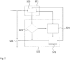
Fig. 2 shows a flow diagram of another embodiment of a method according to the present invention; -
Fig. 3 shows a block diagram of an embodiment of an electronic device according to the present invention; -
Fig. 4 shows an image without motion; -
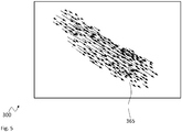
Fig. 5 shows an image with motion vectors; and -
Fig. 6 shows a mask according to the motion vectors ofFig. 5 . - In the figures like reference signs denote like elements unless stated otherwise.
- For sake of clarity in the following description of the method based
Figs. 1 and2 the reference signs used in the description of apparatus basedFig. 3 will be maintained. -
Fig. 1 shows a flow diagram of an embodiment of a method for transmittingdata 150 in avideo 151 that is displayed on adisplay device 101. - The method comprises detecting S1 motion in at least two consecutive frames of the
video 151. In decision D1 it is decided if local motion above a first predetermined threshold level is detected indelimited areas 103 of the at least two consecutive frames. If this is the case, the method continues with encoding S2 thedata 150 in the at least two consecutive frames according to a predetermined visible light data encoding scheme outside of the delimitedareas 103. - Although not shown, it is understood, that if no motion is detected, the
data 150 may be encoded in the complete area of the frames. Further, if global motion above a second predetermined threshold level is detected in the at least two consecutive frames, the trailing frames may be skipped when encoding thedata 150. - It is understood, that the method according to the present invention may e.g. be performed in the signal processing chain of an
electronic device 100 with adisplay device 101. Such anelectronic device 100 may e.g. be a TV set, a video beamer, or any other type of device that is capable of reproducing images of videos. - The motion in the at least two consecutive frames of the
video 151 may e.g. be detected by a motion detection unit, like e.g. amotion detector 102 of a video decoder and/or a mpeg decoder and/or a deinterlacer and/or a complex motion adaptive / compensation frame rate converter and/or a motion estimated motion compensation algorithm. -
Fig. 2 shows a flow diagram of another embodiment of a method for transmittingdata 150 in avideo 151 that is displayed on adisplay device 101. - The method according to
Fig. 2 also comprises the step S21 of detecting motion in at least two consecutive frames of thevideo 151. InFig. 2 the step S21 comprises a sub-step of analyzing the at least two consecutive frames for motion. This sub-step S23 may e.g. be performed in a motion detection unit, like e.g. amotion detector 102 of a video decoder and/or a mpeg decoder and/or a deinterlacer and/or a complex motion adaptive / compensation frame rate converter and/or a motion estimated motion compensation algorithm. - The information from step S21 is used in step S22 of performing the coding multiple times. In decision D21 it is verified if motion detected in step S21 is limited to areas of the at least two subsequent frames that are smaller than a predetermined size threshold value. If the detected motion is larger than the size threshold, the motion is assumed to be global, i.e. the motion affects all or most of the area of the at least two consecutive frames. However, if the motion is smaller than the predetermined size threshold value, in step S24 the affected or delimited areas are determined, and e.g. masked out for the following step of coding the
data 150 into thevideo 151. - According to the method shown in
Fig. 2 , the modulation or encoding is performed in step S25 such that the modification is then applied in step S26. The encoding or modulation may e.g. provide a modification map that determines the type and strength of a modification for each single pixel of the frames of thevideo 151. The modification map may therefore comprise the same number of fields as the frames of thevideo 151 comprise pixels. As alternative, if for example the modification is always applied to blocks of multiple pixels, the modification map may only comprise the number of fields as there are blocks in the frames of thevideo 151. - The content of the fields of the modification map may then e.g. refer to the modification. In an exemplary embodiment, the encoding may e.g. be performed by modifying the brightness or the color hue of the pixels or of blocks of pixels of the frames of the
video 151. The fields of the modification map may then e.g. comprise a value (positive or negative) that may then be added to the brightness value or one or more of the color values of the respective pixel or block of pixels. -
Fig. 3 shows a block diagram of an embodiment of anelectronic device 100 for transmittingdata 150 in avideo 151. Theelectronic device 100 comprises amotion detector 102 that receives thevideo 151 and that is coupled to adata encoder 104. The data encoder receives thevideo 151 and in addition receives thedata 150 that is to be transmitted in thevideo 151. The data encoder 104 is coupled to adisplay device 101. It is understood, that if themotion detector 102 is part of a signal processing chain of theelectronic device 100, themotion detector 102 may also be coupled to other elements of the electronic device 100 (not shown) and thedisplay device 101. - It is understood, that the
display device 101 displays thevideo 151. This may be theplain video 151 or the video with encodeddata 150. - The
motion detector 102 detects motion in at least two consecutive frames of thevideo 151, and thedata encoder 104 encodes thedata 150 in avideo signal 105 that is provided to thedisplay device 101 according to a predetermined visible light data encoding scheme, if local motion above a first predetermined threshold level is detected by themotion detector 102 indelimited areas 103 of the at least two consecutive frames. - If no motion or motion below a predetermined threshold level is detected in the at least two consecutive frames, the
data encoder 104 may encode thedata 150 in the at least two consecutive frames using the complete image area of the at least two consecutive frames. - If global motion above a second predetermined threshold level is detected in the at least two consecutive frames, the
data encoder 104 is configured to skip the trailing frames when encoding thedata 150. The term global motion refers to the areas affected by the motion being larger than a predetermined size. - The data encoder 104 may e.g. comprises a size verification unit that verifies if the size of the delimited
areas 103 is smaller than a predetermined size threshold value, wherein thedata encoder 104 encodes thedata 150 only if the size of the delimitedareas 103 is smaller than the predetermined size threshold value. - In addition, the
data encoder 104 may comprise a masking unit configured to generate an image mask that represents the delimitedareas 103, wherein thedata encoder 104 may encode thedata 150 in the areas of the at least two consecutive frames that are not masked by the image mask. - The
motion detector 102 may comprise a motion detection unit, especially amotion detector 102 of a video decoder and/or a mpeg decoder and/or a deinterlacer and/or a complex motion adaptive / compensation frame rate converter and/or a motion estimated motion compensation algorithm. -
Fig. 4 shows animage 200 without motion. Theimage 200 may e.g. show a landscape with alower portion 261, anupper portion 262 and anobject 263. - The image was taken without any movement of the
object 263 and without any movement of the camera, like e.g. a panning movement. Therefore, the motion detector 102 (seeFig. 3 ) will not detect any motion and the data encoder 104 may use the complete image surface to encode the data 150 (seeFig. 1 ). - It is understood, that the chosen scenery is just exemplarily chosen and that any other scenery may also serve for encoding the
data 150 as good as the chosen scenery, as long as no movement is present in consecutive images or frames. -
Fig. 5 shows animage 300 withmotion vectors 365. Themotion vectors 365 may e.g. refer to the movement of the object shown on thedisplay device 101 of theelectronic device 100 that is marked withmotion vector 152 inFig. 3 . - The
motion vectors 365 characterize the emotion of the object by their direction and their length. Themotion vectors 365 may refer to the movement of an object between two consecutive frames or in a group of frames. - The
motion vectors 365 may serve as a basis, e.g. in the masking unit, that may then generate a respective mask, as shown inFig. 6 . -
Fig. 6 shows amask 466 according to the motion vectors ofFig. 5 . It can be seen, that the mask defines which region of theimage 400 comprises movement, and which region of theimage 400 does not comprise any movement, shown as checkered surface. - It can be seen, that the
mask 466 cuts out the sections of theimage 400 that are affected by the movement of an object as defined by the movement vectors inFig. 5 . - In the further processing according to the present invention, the
mask 466 may then be used to determine, which regions of the frames of the video may be used to encode thedata 150 and which regions may not be used. - Although specific embodiments have been illustrated and described herein, it will be appreciated by those of ordinary skill in the art that a variety of alternate and/or equivalent implementations exist. It should be appreciated that the exemplary embodiment or exemplary embodiments are only examples, and are not intended to limit the scope, applicability, or configuration in any way. Rather, the foregoing summary and detailed description will provide those skilled in the art with a convenient road map for implementing at least one exemplary embodiment, it being understood that various changes may be made in the function and arrangement of elements described in an exemplary embodiment without departing from the scope as set forth in the appended claims and their legal equivalents. Generally, this application is intended to cover any adaptations or variations of the specific embodiments discussed herein.
- The present invention provides a method for transmitting
data 150 in avideo 151 that is displayed on adisplay device 101, the method comprising detecting S1 motion in at least two consecutive frames of thevideo 151, and if local motion above a first predetermined threshold level is detected indelimited areas 103 of the at least two consecutive frames, encoding S2 thedata 150 in the at least two consecutive frames according to a predetermined visible light data encoding scheme outside of the delimitedareas 103. Further, the present invention provides a respectiveelectronic device 100. -
- 100
- electronic device
- 101
- display device
- 102
- motion detector
- 103
- delimited area
- 104
- data encoder
- 105
- video signal
- 150
- data
- 151
- video
- 152
- motion vector
- 200, 300, 400
- image
- 261, 262
- section
- 263
- object
- 365
- motion vectors
- S1, S2, S21, S22, S23, S24, S25, S26
- method steps
- D1, D21
- decision
Claims (12)
- Method for transmitting data (150) in a video (151) that is displayed on a display device (101), the method comprising:detecting (S1) motion in at least two consecutive frames of the video (151),if local motion above a first predetermined threshold level is detected in delimited areas (103) of the at least two consecutive frames, encoding (S2) the data (150) in the at least two consecutive frames according to a predetermined visible light data encoding scheme outside of the delimited areas (103).
- Method according to claim 1, comprising if global motion above a second predetermined threshold level is detected in the at least two consecutive frames, skipping the trailing frames when encoding the data (150).
- Method according to any one of the preceding claims, comprising if no motion or motion below a predetermined threshold level is detected in the at least two consecutive frames, encoding the data (150) in the at least two consecutive frames according to a predetermined encoding scheme using the complete image area of the at least two consecutive frames.
- Method according to any one of the preceding claims, comprising determining the size of the delimited areas (103) and encoding the data (150) only if the size of the delimited areas (103) is smaller than a predetermined size threshold value.
- Method according to any one of the preceding claims, wherein encoding the data (150) outside of the delimited areas (103) comprises generating an image mask that represents the delimited areas (103) and encoding the data (150) in the areas of the at least two consecutive frames that are not masked by the image mask.
- Method according to any one of the preceding claims, wherein the motion in the at least two consecutive frames of the video (151) is detected by a motion detection unit, especially by a motion detector (102) of a video decoder and/or a mpeg decoder and/or a deinterlacer and/or a complex motion adaptive / compensation frame rate converter and/or a motion estimated motion compensation algorithm.
- Electronic device (100) for transmitting data (150) in a video (151), the electronic device (100) comprising:a display device (101) configured to display the video (151),a motion detector (102) configured to detect motion in at least two consecutive frames of the video (151), anda data encoder (104) configured to encode the data (150) in a video signal (105) that is provided to the display device (101) according to a predetermined visible light data encoding scheme if local motion above a first predetermined threshold level is detected by the motion detector (102) in delimited areas (103) of the at least two consecutive frames.
- Electronic device (100) according to claim 7, wherein if global motion above a second predetermined threshold level is detected in the at least two consecutive frames, the data encoder (104) is configured to skip the trailing frames when encoding the data (150).
- Electronic device (100) according to any one of the preceding claims 7 and 8, wherein if no motion or motion below a predetermined threshold level is detected in the at least two consecutive frames, the data encoder (104) is configured to encode the data (150) in the at least two consecutive frames using the complete image area of the at least two consecutive frames.
- Electronic device (100) according to any one of the preceding claims 7 to 9, wherein the data encoder (104) comprises a size verification unit that is configured to verify if the size of the delimited areas (103) is smaller than a predetermined size threshold value and wherein the data encoder (104) is configured to encode the data (150) only if the size of the delimited areas (103) is smaller than the predetermined size threshold value.
- Electronic device (100) according to any one of the preceding claims 7 to 10, wherein the data encoder (104) comprises a masking unit configured to generate an image mask that represents the delimited areas (103), and wherein the data encoder (104) is configured to encode the data (150) in the areas of the at least two consecutive frames that are not masked by the image mask.
- Electronic device (100) according to any one of the preceding claims 7 to 11, wherein the motion detector (102) comprises a motion detection unit, especially a motion detector (102) of a video decoder and/or a mpeg decoder and/or a deinterlacer and/or a complex motion adaptive / compensation frame rate converter and/or a motion estimated motion compensation algorithm.
Priority Applications (1)
| Application Number | Priority Date | Filing Date | Title |
|---|---|---|---|
| EP18157756.0A EP3531584A1 (en) | 2018-02-21 | 2018-02-21 | Method for transmitting data in a video and electronic device |
Applications Claiming Priority (1)
| Application Number | Priority Date | Filing Date | Title |
|---|---|---|---|
| EP18157756.0A EP3531584A1 (en) | 2018-02-21 | 2018-02-21 | Method for transmitting data in a video and electronic device |
Publications (1)
| Publication Number | Publication Date |
|---|---|
| EP3531584A1 true EP3531584A1 (en) | 2019-08-28 |
Family
ID=61256631
Family Applications (1)
| Application Number | Title | Priority Date | Filing Date |
|---|---|---|---|
| EP18157756.0A Ceased EP3531584A1 (en) | 2018-02-21 | 2018-02-21 | Method for transmitting data in a video and electronic device |
Country Status (1)
| Country | Link |
|---|---|
| EP (1) | EP3531584A1 (en) |
Citations (4)
| Publication number | Priority date | Publication date | Assignee | Title |
|---|---|---|---|---|
| US20020027612A1 (en) * | 2000-09-07 | 2002-03-07 | Brill Michael H. | Spatio-temporal channel for images |
| US20130050254A1 (en) * | 2011-08-31 | 2013-02-28 | Texas Instruments Incorporated | Hybrid video and graphics system with automatic content detection process, and other circuits, processes, and systems |
| US20150222355A1 (en) * | 2013-09-04 | 2015-08-06 | Panasonic Corporation | Display device |
| US20160180779A1 (en) * | 2013-10-25 | 2016-06-23 | Panasonic Corporation | Display device and method of controlling the same |
-
2018
- 2018-02-21 EP EP18157756.0A patent/EP3531584A1/en not_active Ceased
Patent Citations (4)
| Publication number | Priority date | Publication date | Assignee | Title |
|---|---|---|---|---|
| US20020027612A1 (en) * | 2000-09-07 | 2002-03-07 | Brill Michael H. | Spatio-temporal channel for images |
| US20130050254A1 (en) * | 2011-08-31 | 2013-02-28 | Texas Instruments Incorporated | Hybrid video and graphics system with automatic content detection process, and other circuits, processes, and systems |
| US20150222355A1 (en) * | 2013-09-04 | 2015-08-06 | Panasonic Corporation | Display device |
| US20160180779A1 (en) * | 2013-10-25 | 2016-06-23 | Panasonic Corporation | Display device and method of controlling the same |
Non-Patent Citations (1)
| Title |
|---|
| S. SHI, READING BETWEEN LINES: HIGH-RATE, NON-INTRUSIVE VISUAL CODES WITHIN REGULAR VIDEOS VIA IMPLICITCODE |
Similar Documents
| Publication | Publication Date | Title |
|---|---|---|
| JP5608834B1 (en) | Video display method | |
| CN104885382B (en) | Visible light communication signal display method and display device | |
| US10277901B2 (en) | Encoding a video stream having a privacy mask | |
| EP3796655B1 (en) | Video privacy mask in forward predicted video frame | |
| US9582842B2 (en) | Position information adding apparatus, position information adding method, and computer program for adding position information and position detection apparatus | |
| CN116113970A (en) | Systems and methods for applying adaptive video watermarking | |
| JP5230756B2 (en) | Video display device | |
| US10070067B2 (en) | Systems, methods, and media for extracting information and a display image from two captured images | |
| Chalmers et al. | HDR video past, present and future: A perspective | |
| Izz et al. | Uber-in-light: Unobtrusive visible light communication leveraging complementary color channel | |
| US10152946B2 (en) | Video display method using visible/visual light communication with stripe patterns having different orientations and color combinations | |
| JP5950605B2 (en) | Image processing system and image processing method | |
| Tran et al. | Deeplight: Robust & unobtrusive real-time screen-camera communication for real-world displays | |
| US8520742B2 (en) | Moving image compression-coding device, method of compression-coding moving image, and H.264 moving image compression-coding device | |
| Nishar et al. | REVELIO: A real-world screen-camera communication system with visually imperceptible data embedding | |
| Kim et al. | Video display field communication: Practical design and performance analysis | |
| CN113099237A (en) | Video processing method and device | |
| Abe et al. | Screen-camera communication via matrix barcode utilizing imperceptible color vibration | |
| US9967567B2 (en) | Method and system for enhancing image quality of compressed video stream | |
| US8374382B2 (en) | Device for processing video images, video projection system and signal intended for use by the projection system | |
| CN115834952B (en) | A Visual Perception-Based Video Frame Rate Detection Method and Device | |
| WO2019092392A1 (en) | Method and system for processing display data | |
| Ryu et al. | Spatial Frequency Modulation for Display-Camera Communication | |
| US8867842B2 (en) | Image processing device producing a single-viewpoint image based on a plurality of images viewed from a plurality of viewing points, image processing system producing a single-viewpoint image based on a plurality of images viewed from a plurality of viewing points, and image processing method producing a single-viewpoint image based on a plurality of images viewed from a plurality of viewing points | |
| KR20120105968A (en) | Erroneously compressed video detection method and its device |
Legal Events
| Date | Code | Title | Description |
|---|---|---|---|
| PUAI | Public reference made under article 153(3) epc to a published international application that has entered the european phase |
Free format text: ORIGINAL CODE: 0009012 |
|
| STAA | Information on the status of an ep patent application or granted ep patent |
Free format text: STATUS: THE APPLICATION HAS BEEN PUBLISHED |
|
| AK | Designated contracting states |
Kind code of ref document: A1 Designated state(s): AL AT BE BG CH CY CZ DE DK EE ES FI FR GB GR HR HU IE IS IT LI LT LU LV MC MK MT NL NO PL PT RO RS SE SI SK SM TR |
|
| AX | Request for extension of the european patent |
Extension state: BA ME |
|
| STAA | Information on the status of an ep patent application or granted ep patent |
Free format text: STATUS: REQUEST FOR EXAMINATION WAS MADE |
|
| 17P | Request for examination filed |
Effective date: 20200210 |
|
| RBV | Designated contracting states (corrected) |
Designated state(s): AL AT BE BG CH CY CZ DE DK EE ES FI FR GB GR HR HU IE IS IT LI LT LU LV MC MK MT NL NO PL PT RO RS SE SI SK SM TR |
|
| STAA | Information on the status of an ep patent application or granted ep patent |
Free format text: STATUS: EXAMINATION IS IN PROGRESS |
|
| 17Q | First examination report despatched |
Effective date: 20210408 |
|
| STAA | Information on the status of an ep patent application or granted ep patent |
Free format text: STATUS: THE APPLICATION HAS BEEN REFUSED |
|
| 18R | Application refused |
Effective date: 20230415 |