EP3531530B1 - Compression-type charging device - Google Patents
Compression-type charging device Download PDFInfo
- Publication number
- EP3531530B1 EP3531530B1 EP17863070.3A EP17863070A EP3531530B1 EP 3531530 B1 EP3531530 B1 EP 3531530B1 EP 17863070 A EP17863070 A EP 17863070A EP 3531530 B1 EP3531530 B1 EP 3531530B1
- Authority
- EP
- European Patent Office
- Prior art keywords
- spring
- charging
- positive electrode
- cigarette
- cigarette case
- Prior art date
- Legal status (The legal status is an assumption and is not a legal conclusion. Google has not performed a legal analysis and makes no representation as to the accuracy of the status listed.)
- Active
Links
Images
Classifications
-
- A—HUMAN NECESSITIES
- A24—TOBACCO; CIGARS; CIGARETTES; SIMULATED SMOKING DEVICES; SMOKERS' REQUISITES
- A24F—SMOKERS' REQUISITES; MATCH BOXES; SIMULATED SMOKING DEVICES
- A24F15/00—Receptacles or boxes specially adapted for cigars, cigarettes, simulated smoking devices or cigarettes therefor
-
- A—HUMAN NECESSITIES
- A24—TOBACCO; CIGARS; CIGARETTES; SIMULATED SMOKING DEVICES; SMOKERS' REQUISITES
- A24F—SMOKERS' REQUISITES; MATCH BOXES; SIMULATED SMOKING DEVICES
- A24F15/00—Receptacles or boxes specially adapted for cigars, cigarettes, simulated smoking devices or cigarettes therefor
- A24F15/12—Receptacles or boxes specially adapted for cigars, cigarettes, simulated smoking devices or cigarettes therefor for pocket use
- A24F15/18—Receptacles or boxes specially adapted for cigars, cigarettes, simulated smoking devices or cigarettes therefor for pocket use combined with other objects
-
- A—HUMAN NECESSITIES
- A24—TOBACCO; CIGARS; CIGARETTES; SIMULATED SMOKING DEVICES; SMOKERS' REQUISITES
- A24F—SMOKERS' REQUISITES; MATCH BOXES; SIMULATED SMOKING DEVICES
- A24F40/00—Electrically operated smoking devices; Component parts thereof; Manufacture thereof; Maintenance or testing thereof; Charging means specially adapted therefor
- A24F40/90—Arrangements or methods specially adapted for charging batteries thereof
- A24F40/95—Arrangements or methods specially adapted for charging batteries thereof structurally associated with cases
-
- A—HUMAN NECESSITIES
- A24—TOBACCO; CIGARS; CIGARETTES; SIMULATED SMOKING DEVICES; SMOKERS' REQUISITES
- A24F—SMOKERS' REQUISITES; MATCH BOXES; SIMULATED SMOKING DEVICES
- A24F9/00—Accessories for smokers' pipes
- A24F9/16—Protective coverings or cases for pipes or parts thereof
-
- H—ELECTRICITY
- H02—GENERATION; CONVERSION OR DISTRIBUTION OF ELECTRIC POWER
- H02J—ELECTRIC POWER NETWORKS; CIRCUIT ARRANGEMENTS OR SYSTEMS FOR SUPPLYING OR DISTRIBUTING ELECTRIC POWER; SYSTEMS FOR STORING ELECTRIC ENERGY
- H02J7/00—Circuit arrangements for charging or discharging batteries or for supplying loads from batteries
- H02J7/70—Circuit arrangements for charging or discharging batteries or for supplying loads from batteries characterised by the mechanical construction
- H02J7/751—Circuit arrangements for charging or discharging batteries or for supplying loads from batteries characterised by the mechanical construction concerning the insertion or the connection of the batteries
Definitions
- the present invention belongs to the field of electronic cigarette, specifically relates to a compression charging device.
- the existing charging devices for cigarette case are point-contact charging devices. Positive contacts and negative contacts are respectively led out from the Print Circuit Board (PCB) of a cigarette case and an end surface of a cigarette set. When the cigarette case is closed, an elastic body inside the cigarette case compresses the cigarette set, so that the positive and negative contacts on a contact surface of the cigarette set and the cigarette case completely contact each other for charging.
- PCB Print Circuit Board
- WO 2016 / 012 811 A1 discloses a pack for holding and re-charging an e-cigarette having a tip connector with charging contacts.
- WO 2017 1153 577 A1 describes a personal charging case for an e-vaping device with a body for partially enclosing the e-vaping device.
- WO 2015 / 023 996 A2 discloses a device for detecting and charging a battery in an electronic cigarette having a microcomputer.
- GB 2 528 712 A describes a pack for holding and re-charging an e-cigarette which itself is rechargeable.
- the compression charging device includes a cigarette case charging part and a cigarette set charging part.
- the cigarette case charging part includes a positive electrode cover 1, wherein the positive electrode cover 1 includes a cylindrical upper portion and a drum-shaped lower portion; a positive electrode column 2, wherein the positive electrode column 2 includes an upper portion located inside the drum-shaped lower portion of the positive electrode cover 1; a positive spring 6, wherein the positive spring 6 is located inside a spring cap 3, the positive spring 6 has an upper portion connected to a lower surface of the positive electrode column 2 and a lower portion connected to a charging spring seat 4, and the charging spring seat 4 is connected to a positive electrode of a power supply of a cigarette case; a negative spring 5 connected to a negative electrode of the power supply of the cigarette case; a charging insulation sleeve 7 located between the charging spring seat 4 and the negative spring 5; and a PCB 8, wherein the PCB is connected to the charging spring seat 4, the negative spring 5, and the charging insulation sleeve 7.
- the cigarette set charging part includes a filter holding seat 9 connected to a positive electrode of the cigarette set, wherein an overall structure of the filter holding seat 9 is drum-shaped, and a lower surface of the filter holding seat 9 is matched with the positive electrode cover 1; a charging base 11 connected to a negative electrode of the cigarette set, wherein an overall structure of the charging base 11 is drum-shaped, and a lower surface of the charging base 11 is matched with an upper surface of the negative spring 5; and an insulation fixing sleeve 10 located between the filter holding seat 9 and the charging base 11.
- the charging spring seat 4 and the negative spring 5 are connected to the PCB 8 by a stannum solder.
- the positive electrode cover 1 is connected to the positive electrode column 2 through a press riveting.
- the spring cap 3 is connected to the charging spring seat 4 through a press riveting.
- the lower portion of the positive electrode cover 1 extends into the spring cap 3, and an inner protrusion edge on an upper portion of the spring cap 3 is matched with an outer protrusion edge on a lower portion of the positive electrode cover 1.
- the working principle of the compression charging device of the present invention is as follows.
- the charging spring seat 4 and the negative spring 5 of the cigarette case are separated from each other through the charging insulation sleeve 7, and are respectively connected to the positive and negative electrodes.
- the PCB 8 is respectively connected to the negative spring 5 and the charging spring seat 4 through stannum solder.
- the filter holding seat 9 of the cigarette set is separated from the charging base 11 through the insulation fixing sleeve 10, and the filter holding seat 9 and the charging base 11 are respectively connected to the positive and negative electrodes.
- the cigarette case cover compresses the cigarette set.
- the filter holding seat 9 of the cigarette set contacts the surface of the positive electrode cover 1 of the cigarette case, and the positive electrode cover 1 is connected to the positive electrode column 2 through the press riveting.
- the positive electrode column 2 and the positive spring 6 are put into the charging spring seat 4, and connected to the charging spring seat 4 through the spring cap 3 by press riveting.
- the positive spring 6 is in a compression state, and the positive electrode of the cigarette set is in an electrical connection to the cigarette case.
- the charging base 11 of the cigarette set contacts and tightly compresses the surface of the negative spring 5, and the negative electrode of the cigarette set is in an electrical connection to the cigarette case, so the cigarette set gets charged.
- the filter holding seat 9 of the cigarette set is separated from the surface of the positive electrode cover 1, the positive electrode of the cigarette set is not in an electrical connection to the cigarette case, and the cigarette set can be taken out from the cigarette case.
- the present invention has the following advantages.
- a compression charging device for cigarette set to get charged is firstly developed in the present invention.
- the negative spring and the positive spring have a double function of electrical conduction and bouncing.
- the reference designators in the drawings arc described below: 1-positivc electrode cover; 2-positive electrode column; 3-spring cap; 4-charging spring seat; 5-negative spring; 6-positive spring; 7-charging insulation sleeve; 8-PCB; 9-filter holding seat; 10-insulation fixing sleeve; 11-charging base.
- the cigarette case cover compresses the cigarette set.
- the filter holding seat 9 of the cigarette set contacts the surface of the positive electrode cover 1, and the positive electrode cover 1 is connected to the positive electrode column 2 through the press riveting.
- the positive electrode column 2 and the positive spring 6 are put into the charging spring seat 4, and connected to the charging spring seat 4 through the spring cap 3 by press riveting.
- the positive spring 6 is in a compression state, and the positive electrode of the cigarette set is in an electrical connection to the cigarette case.
- the charging base 11 of the cigarette set tightly compresses the negative spring 5 of the cigarette case, the negative electrode of the cigarette set is in an electrical connection to the cigarette case, so as to make the cigarette set get charged.
- the filter holding seat 9 of the cigarette set is separated from the surface of the positive electrode cover 1, the positive electrode of the cigarette set is not in an electrical connection to the cigarette case, and the cigarette set can be taken out from the cigarette case.
Landscapes
- Engineering & Computer Science (AREA)
- Power Engineering (AREA)
- Charge And Discharge Circuits For Batteries Or The Like (AREA)
- Packaging Of Annular Or Rod-Shaped Articles, Wearing Apparel, Cassettes, Or The Like (AREA)
- Secondary Cells (AREA)
- Electrostatic Separation (AREA)
- Manufacturing Of Cigar And Cigarette Tobacco (AREA)
Description
- The present invention belongs to the field of electronic cigarette, specifically relates to a compression charging device.
- The existing charging devices for cigarette case are point-contact charging devices. Positive contacts and negative contacts are respectively led out from the Print Circuit Board (PCB) of a cigarette case and an end surface of a cigarette set. When the cigarette case is closed, an elastic body inside the cigarette case compresses the cigarette set, so that the positive and negative contacts on a contact surface of the cigarette set and the cigarette case completely contact each other for charging.
WO 2016 / 012 811 A1 discloses a pack for holding and re-charging an e-cigarette having a tip connector with charging contacts.WO 2017 1153 577 A1 WO 2015 / 023 996 A2 discloses a device for detecting and charging a battery in an electronic cigarette having a microcomputer.GB 2 528 712 A - Based on the existing point-contact charging device for cigarette case, a compression charging device is developed in the present invention. The compression charging device includes a cigarette case charging part and a cigarette set charging part.
- The cigarette case charging part includes a positive electrode cover 1, wherein the positive electrode cover 1 includes a cylindrical upper portion and a drum-shaped lower portion; a positive electrode column 2, wherein the positive electrode column 2 includes an upper portion located inside the drum-shaped lower portion of the positive electrode cover 1; a
positive spring 6, wherein thepositive spring 6 is located inside aspring cap 3, thepositive spring 6 has an upper portion connected to a lower surface of the positive electrode column 2 and a lower portion connected to acharging spring seat 4, and thecharging spring seat 4 is connected to a positive electrode of a power supply of a cigarette case; anegative spring 5 connected to a negative electrode of the power supply of the cigarette case; acharging insulation sleeve 7 located between thecharging spring seat 4 and thenegative spring 5; and a PCB 8, wherein the PCB is connected to thecharging spring seat 4, thenegative spring 5, and the charging insulation sleeve 7. - The cigarette set charging part includes a filter holding seat 9 connected to a positive electrode of the cigarette set, wherein an overall structure of the filter holding seat 9 is drum-shaped, and a lower surface of the filter holding seat 9 is matched with the positive electrode cover 1; a charging base 11 connected to a negative electrode of the cigarette set, wherein an overall structure of the charging base 11 is drum-shaped, and a lower surface of the charging base 11 is matched with an upper surface of the
negative spring 5; and aninsulation fixing sleeve 10 located between the filter holding seat 9 and the charging base 11. - Preferably, the
charging spring seat 4 and thenegative spring 5 are connected to the PCB 8 by a stannum solder. - Preferably, the positive electrode cover 1 is connected to the positive electrode column 2 through a press riveting.
- Preferably, the
spring cap 3 is connected to thecharging spring seat 4 through a press riveting. - Preferably, the lower portion of the positive electrode cover 1 extends into the
spring cap 3, and an inner protrusion edge on an upper portion of thespring cap 3 is matched with an outer protrusion edge on a lower portion of the positive electrode cover 1. - The working principle of the compression charging device of the present invention is as follows.
- The
charging spring seat 4 and thenegative spring 5 of the cigarette case are separated from each other through thecharging insulation sleeve 7, and are respectively connected to the positive and negative electrodes. The PCB 8 is respectively connected to thenegative spring 5 and thecharging spring seat 4 through stannum solder. The filter holding seat 9 of the cigarette set is separated from the charging base 11 through theinsulation fixing sleeve 10, and the filter holding seat 9 and the charging base 11 are respectively connected to the positive and negative electrodes. - When the cigarette set is placed into the cigarette case, the cigarette case cover compresses the cigarette set. The filter holding seat 9 of the cigarette set contacts the surface of the positive electrode cover 1 of the cigarette case, and the positive electrode cover 1 is connected to the positive electrode column 2 through the press riveting. The positive electrode column 2 and the
positive spring 6 are put into thecharging spring seat 4, and connected to thecharging spring seat 4 through thespring cap 3 by press riveting. Thepositive spring 6 is in a compression state, and the positive electrode of the cigarette set is in an electrical connection to the cigarette case. The charging base 11 of the cigarette set contacts and tightly compresses the surface of thenegative spring 5, and the negative electrode of the cigarette set is in an electrical connection to the cigarette case, so the cigarette set gets charged. - When the cigarette case is opened, the cigarette set is bounced by the
negative spring 6 of the cigarette case, the filter holding seat 9 of the cigarette set is separated from the surface of the positive electrode cover 1, the positive electrode of the cigarette set is not in an electrical connection to the cigarette case, and the cigarette set can be taken out from the cigarette case. - The present invention has the following advantages.
- Based on the existing point-contact charging device, a compression charging device for cigarette set to get charged is firstly developed in the present invention. The negative spring and the positive spring have a double function of electrical conduction and bouncing.
-
-
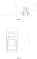
FIG. 1 is a schematic diagram of a cigarette case charging part of the present invention; -
FIG. 2 is a schematic diagram of a cigarette set charging part of the present invention; and -
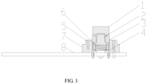
FIG. 3 is schematic diagram showing a compression state (charging state) of a cigarette case charging part of the present invention. - The reference designators in the drawings arc described below: 1-positivc electrode cover; 2-positive electrode column; 3-spring cap; 4-charging spring seat; 5-negative spring; 6-positive spring; 7-charging insulation sleeve; 8-PCB; 9-filter holding seat; 10-insulation fixing sleeve; 11-charging base.
- When the cigarette set is placed into the cigarette case, the cigarette case cover compresses the cigarette set. The filter holding seat 9 of the cigarette set contacts the surface of the positive electrode cover 1, and the positive electrode cover 1 is connected to the positive electrode column 2 through the press riveting. The positive electrode column 2 and the
positive spring 6 are put into thecharging spring seat 4, and connected to thecharging spring seat 4 through thespring cap 3 by press riveting. Thepositive spring 6 is in a compression state, and the positive electrode of the cigarette set is in an electrical connection to the cigarette case. The charging base 11 of the cigarette set tightly compresses thenegative spring 5 of the cigarette case, the negative electrode of the cigarette set is in an electrical connection to the cigarette case, so as to make the cigarette set get charged. - When the cigarette case is opened, the cigarette set is bounced by the
negative spring 6 of the cigarette case, the filter holding seat 9 of the cigarette set is separated from the surface of the positive electrode cover 1, the positive electrode of the cigarette set is not in an electrical connection to the cigarette case, and the cigarette set can be taken out from the cigarette case.
Claims (1)
- A compression charging device, comprising a cigarette case charging part and a cigarette set charging part; whereinthe cigarette case charging part comprises a positive electrode cover (1), wherein the positive electrode cover (1) comprises a cylindrical upper portion and a drum-shaped lower portion; a positive electrode column (2), wherein an upper portion of the positive electrode column (2) is located inside the drum-shaped lower portion of the positive electrode cover (1); a positive spring (6), wherein the positive spring (6) is located inside a spring cap (3), an upper portion of the positive spring (6) is connected to a lower surface of the positive electrode column (2), a lower portion of the positive spring (6) is connected to a charging spring seat (4), and the charging spring seat (4) is connected to a positive electrode of a power supply of a cigarette case; a negative spring (5) connected to a negative electrode of the power supply of the cigarette case; a charging insulation sleeve (7) located between the charging spring seat (4) and the negative spring (5); and a PCB (8) connected to the charging spring seat (4), the negative spring (5), and the charging insulation sleeve (7); wherein the lower portion of the positive electrode cover (1) extends into the spring cap (3), and an inner protrusion edge on an upper portion of the spring cap (3) is matched with an outer protrusion edge on the lower portion of the positive electrode cover (1); wherein the charging spring seat (4) and the negative spring (5) are connected to the PCB (8) by a stannum solder; wherein the positive electrode cover (1) is connected to the positive electrode column (2) through a press riveting; wherein the spring cap (3) is connected to the charging spring seat (4) through a press riveting; andthe cigarette set charging part comprises a filter holding seat (9), wherein the filter holding seat (9) is connected to a positive electrode of a cigarette set, an overall structure of the filter holding seat (9) is drum-shaped, and a lower surface of the filter holding seat (9) is matched with the positive electrode cover (1); a charging base (11), wherein the charging base (11) is connected to a negative electrode of the cigarette set, an overall structure of the charging base (11) is drum-shaped, and a lower surface of the charging base (11) is matched with an upper surface of the negative spring (5); and an insulation fixing sleeve (10) located between the filter holding seat (9) and the charging base (11),wherein the method of compression charging device for cigarette set to get charged is as follows:When the cigarette set is placed into the cigarette case, the cigarette case cover compresses the cigarette set, the filter holding seat (9) of the cigarette set contacts the surface of the positive electrode cover (1) of the cigarette case, and the positive electrode cover (1) is connected to the positive electrode column (2) through the press riveting; the positive electrode column (2) and the positive spring (6) are put into the charging spring seat (4), and connected to the charging spring seat (4) through the spring cap (3) by press riveting; the positive spring (6) is in a compression state, and the positive electrode of the cigarette set is in an electrical connection to the cigarette case; the charging base (11) of the cigarette set contacts and tightly compresses the surface of the negative spring (5), and the negative electrode of the cigarette set is in an electrical connection to the cigarette case, so the cigarette set gets charged,When the cigarette case is opened, the cigarette set is bounced by the negative spring (6) of the cigarette case, the filter holding seat (9) of the cigarette set is separated from the surface of the positive electrode cover (1), the positive electrode of the cigarette set is not in an electrical connection to the cigarette case, and the cigarette set can be taken out from the cigarette case.
Applications Claiming Priority (2)
| Application Number | Priority Date | Filing Date | Title |
|---|---|---|---|
| CN201610905471.6A CN106655327A (en) | 2016-10-18 | 2016-10-18 | Compression type charging device |
| PCT/CN2017/106531 WO2018072681A1 (en) | 2016-10-18 | 2017-10-17 | Compression-type charging device |
Publications (3)
| Publication Number | Publication Date |
|---|---|
| EP3531530A1 EP3531530A1 (en) | 2019-08-28 |
| EP3531530A4 EP3531530A4 (en) | 2020-06-10 |
| EP3531530B1 true EP3531530B1 (en) | 2025-01-01 |
Family
ID=58856814
Family Applications (1)
| Application Number | Title | Priority Date | Filing Date |
|---|---|---|---|
| EP17863070.3A Active EP3531530B1 (en) | 2016-10-18 | 2017-10-17 | Compression-type charging device |
Country Status (8)
| Country | Link |
|---|---|
| US (1) | US11160315B2 (en) |
| EP (1) | EP3531530B1 (en) |
| JP (1) | JP6917450B2 (en) |
| KR (1) | KR102228077B1 (en) |
| CN (1) | CN106655327A (en) |
| RU (1) | RU2706112C1 (en) |
| UA (1) | UA124113C2 (en) |
| WO (1) | WO2018072681A1 (en) |
Families Citing this family (3)
| Publication number | Priority date | Publication date | Assignee | Title |
|---|---|---|---|---|
| CN106655327A (en) * | 2016-10-18 | 2017-05-10 | 云南中烟工业有限责任公司 | Compression type charging device |
| CN107087818B (en) * | 2017-05-16 | 2023-10-27 | 达州市天宝锦湖电子有限公司 | A contact charging electrode structure for electronic cigarettes |
| WO2021074436A1 (en) * | 2019-10-17 | 2021-04-22 | Philip Morris Products S.A. | Charger and aerosol-generating system with a multi-component cover |
Family Cites Families (21)
| Publication number | Priority date | Publication date | Assignee | Title |
|---|---|---|---|---|
| CN201571500U (en) * | 2009-11-12 | 2010-09-08 | 深圳市博格科技有限公司 | Portable traveling charging cigarette case for electronic cigarettes |
| CN201591127U (en) * | 2010-02-25 | 2010-09-29 | 刘翔 | Electronic cigarette case |
| WO2013112549A1 (en) | 2012-01-24 | 2013-08-01 | Sanford Research/USD | Polynucleotides for treating oncogenic viral polypeptide positive tumors |
| CN104010533B (en) * | 2012-06-20 | 2017-05-24 | 惠州市吉瑞科技有限公司 | Electronic cigarette case |
| US10098383B2 (en) * | 2013-08-15 | 2018-10-16 | Fontem Holdings 4 B.V. | Method, system and device for switchless detection and charging |
| CN203424298U (en) * | 2013-08-16 | 2014-02-12 | 刘秋明 | Electronic cigarette set, electronic cigarette and battery assembly of electronic cigarette |
| CN105592730B (en) * | 2013-09-25 | 2019-08-02 | 吉瑞高新科技股份有限公司 | Electronic cigarette charging device and assembly method thereof |
| CN203537022U (en) * | 2013-10-31 | 2014-04-09 | 刘秋明 | An electronic cigarette charging device |
| EP3064078A4 (en) * | 2013-10-31 | 2017-03-29 | Kimree Hi-Tech Inc. | Electronic cigarette charging apparatus and charging method therefor |
| GB201413032D0 (en) * | 2014-02-28 | 2014-09-03 | Beyond Twenty Ltd | Beyond 7 |
| US9974332B2 (en) * | 2014-02-28 | 2018-05-22 | Huizhou Kimree Technology Co., Ltd. Shenzhen Branch | Electronic cigarette charging dock, electronic cigarette case, and method for use thereof |
| CN103859607B (en) * | 2014-03-18 | 2016-03-30 | 深圳市博迪科技开发有限公司 | There is electronic cigarette packet and the electronic cigarette of magnetic-type charge function |
| GB2528710B (en) * | 2014-07-24 | 2018-12-26 | Nicoventures Holdings Ltd | E-cigarette re-charging system |
| GB2528712B (en) * | 2014-07-29 | 2019-03-27 | Nicoventures Holdings Ltd | E-cigarette and re-charging pack |
| CN204812050U (en) * | 2015-07-29 | 2015-12-02 | 深圳赣锋安科有限公司 | Rome cylindricality electron cigarette power supply unit |
| CN104997166A (en) * | 2015-08-14 | 2015-10-28 | 刘团芳 | Temperature-controlled electronic cigarette |
| US20170258135A1 (en) * | 2016-03-11 | 2017-09-14 | Altria Client Services Llc | Personal charging case for electronic vaping device |
| JP6637851B2 (en) | 2016-07-21 | 2020-01-29 | ホーチキ株式会社 | Electrostatic spray generator |
| CN106655327A (en) * | 2016-10-18 | 2017-05-10 | 云南中烟工业有限责任公司 | Compression type charging device |
| CN206117234U (en) * | 2016-10-18 | 2017-04-19 | 云南中烟工业有限责任公司 | Compression charging device |
| CA3046954C (en) * | 2016-12-12 | 2024-01-02 | Vmr Products Llc | Refillable cartridge for vaporizer |
-
2016
- 2016-10-18 CN CN201610905471.6A patent/CN106655327A/en active Pending
-
2017
- 2017-10-17 KR KR1020197008937A patent/KR102228077B1/en not_active Expired - Fee Related
- 2017-10-17 WO PCT/CN2017/106531 patent/WO2018072681A1/en not_active Ceased
- 2017-10-17 EP EP17863070.3A patent/EP3531530B1/en active Active
- 2017-10-17 UA UAA201904032A patent/UA124113C2/en unknown
- 2017-10-17 JP JP2019517781A patent/JP6917450B2/en not_active Expired - Fee Related
- 2017-10-17 US US16/341,451 patent/US11160315B2/en not_active Expired - Fee Related
- 2017-10-17 RU RU2019111545A patent/RU2706112C1/en active
Also Published As
| Publication number | Publication date |
|---|---|
| KR102228077B1 (en) | 2021-03-16 |
| WO2018072681A1 (en) | 2018-04-26 |
| KR20190046908A (en) | 2019-05-07 |
| EP3531530A4 (en) | 2020-06-10 |
| EP3531530A1 (en) | 2019-08-28 |
| US20190267823A1 (en) | 2019-08-29 |
| UA124113C2 (en) | 2021-07-21 |
| JP2019533972A (en) | 2019-11-21 |
| JP6917450B2 (en) | 2021-08-11 |
| RU2706112C1 (en) | 2019-11-14 |
| US11160315B2 (en) | 2021-11-02 |
| CN106655327A (en) | 2017-05-10 |
Similar Documents
| Publication | Publication Date | Title |
|---|---|---|
| US9615606B2 (en) | Electronic cigarette charging device | |
| EP4429012A3 (en) | Battery cell, battery, electrical device, and manufacturing method and device for battery cell | |
| EP2733817B1 (en) | USB-connector within cigarette lighter socket of a vehicle | |
| EP3531530B1 (en) | Compression-type charging device | |
| ATE550793T1 (en) | RECHARGEABLE BATTERY | |
| CN205985094U (en) | Novel 1. 5V lithium ion cylinder battery that use microUSB charges | |
| WO2019084973A1 (en) | Safe and high-energy usb rechargeable battery | |
| WO2016101701A1 (en) | Improved rechargeable battery assembly | |
| JP3131098U (en) | Power tool battery | |
| CN204070552U (en) | Electronic cigarette electric supply installation, electronic cigarette and charging device thereof | |
| CN103349364A (en) | Button-type electronic cigarette, button switch and battery pack | |
| CN107681068B (en) | Rechargeable battery with integrated battery cell | |
| CN107834123B (en) | Safe and high-energy USB rechargeable battery | |
| US20240234837A1 (en) | Improved rechargeable lithium battery assembly | |
| CN205900734U (en) | Lithium cell with reduce output voltage function | |
| CN210167477U (en) | Cylindrical battery with magnetic attraction type charging structure | |
| CN218215940U (en) | Vehicle-mounted charger | |
| CN212062607U (en) | Cylindrical battery with charge-discharge protection circuit | |
| CN206134873U (en) | Explosion-proof lithium battery with pre-warning timer | |
| CN205842739U (en) | A kind of direct charged lighter of replaceable electrothermal silk | |
| CN208862595U (en) | Mobile charging power supply | |
| CN211428304U (en) | A USB rechargeable battery | |
| CN201715254U (en) | Rechargeable electric torch | |
| CN206313478U (en) | A kind of onboard charger | |
| CN107706444B (en) | A battery cell assembly structure and a USB rechargeable battery using the same |
Legal Events
| Date | Code | Title | Description |
|---|---|---|---|
| STAA | Information on the status of an ep patent application or granted ep patent |
Free format text: STATUS: THE INTERNATIONAL PUBLICATION HAS BEEN MADE |
|
| PUAI | Public reference made under article 153(3) epc to a published international application that has entered the european phase |
Free format text: ORIGINAL CODE: 0009012 |
|
| STAA | Information on the status of an ep patent application or granted ep patent |
Free format text: STATUS: REQUEST FOR EXAMINATION WAS MADE |
|
| 17P | Request for examination filed |
Effective date: 20190411 |
|
| AK | Designated contracting states |
Kind code of ref document: A1 Designated state(s): AL AT BE BG CH CY CZ DE DK EE ES FI FR GB GR HR HU IE IS IT LI LT LU LV MC MK MT NL NO PL PT RO RS SE SI SK SM TR |
|
| AX | Request for extension of the european patent |
Extension state: BA ME |
|
| DAV | Request for validation of the european patent (deleted) | ||
| DAX | Request for extension of the european patent (deleted) | ||
| A4 | Supplementary search report drawn up and despatched |
Effective date: 20200512 |
|
| RIC1 | Information provided on ipc code assigned before grant |
Ipc: A24F 15/00 20200101ALI20200506BHEP Ipc: H02J 7/00 20060101AFI20200506BHEP |
|
| STAA | Information on the status of an ep patent application or granted ep patent |
Free format text: STATUS: EXAMINATION IS IN PROGRESS |
|
| RIN1 | Information on inventor provided before grant (corrected) |
Inventor name: FANG, FENGREN Inventor name: LUO, HONGYONG Inventor name: CHEN, YONGKUAN Inventor name: LI, SHIWEI Inventor name: ZHAO, CHANGSHAN Inventor name: YUAN, DALIN Inventor name: LI, ZHIQIANG Inventor name: SHANG, SHANZHAI Inventor name: LEI, PING Inventor name: HAN, JINGMEI Inventor name: ZENG, XU Inventor name: WANG, CHENGYA Inventor name: WANG, RU |
|
| 17Q | First examination report despatched |
Effective date: 20210922 |
|
| GRAP | Despatch of communication of intention to grant a patent |
Free format text: ORIGINAL CODE: EPIDOSNIGR1 |
|
| STAA | Information on the status of an ep patent application or granted ep patent |
Free format text: STATUS: GRANT OF PATENT IS INTENDED |
|
| INTG | Intention to grant announced |
Effective date: 20240919 |
|
| RIN1 | Information on inventor provided before grant (corrected) |
Inventor name: FANG, FENGREN Inventor name: LUO, HONGYONG Inventor name: CHEN, YONGKUAN Inventor name: LI, SHIWEI Inventor name: SHANG, SHANZHAI Inventor name: LEI, PING Inventor name: ZENG, XU Inventor name: WANG, RU Inventor name: HAN, JINGMEI Inventor name: LI, ZHIQIANG Inventor name: YUAN, DALIN |
|
| GRAS | Grant fee paid |
Free format text: ORIGINAL CODE: EPIDOSNIGR3 |
|
| GRAA | (expected) grant |
Free format text: ORIGINAL CODE: 0009210 |
|
| STAA | Information on the status of an ep patent application or granted ep patent |
Free format text: STATUS: THE PATENT HAS BEEN GRANTED |
|
| P01 | Opt-out of the competence of the unified patent court (upc) registered |
Free format text: CASE NUMBER: APP_59016/2024 Effective date: 20241029 |
|
| AK | Designated contracting states |
Kind code of ref document: B1 Designated state(s): AL AT BE BG CH CY CZ DE DK EE ES FI FR GB GR HR HU IE IS IT LI LT LU LV MC MK MT NL NO PL PT RO RS SE SI SK SM TR |
|
| REG | Reference to a national code |
Ref country code: GB Ref legal event code: FG4D |
|
| REG | Reference to a national code |
Ref country code: CH Ref legal event code: EP |
|
| REG | Reference to a national code |
Ref country code: DE Ref legal event code: R096 Ref document number: 602017087136 Country of ref document: DE |
|
| REG | Reference to a national code |
Ref country code: IE Ref legal event code: FG4D |
|
| REG | Reference to a national code |
Ref country code: LT Ref legal event code: MG9D |
|
| REG | Reference to a national code |
Ref country code: NL Ref legal event code: MP Effective date: 20250101 |
|
| REG | Reference to a national code |
Ref country code: AT Ref legal event code: MK05 Ref document number: 1757306 Country of ref document: AT Kind code of ref document: T Effective date: 20250101 |
|
| PG25 | Lapsed in a contracting state [announced via postgrant information from national office to epo] |
Ref country code: NL Free format text: LAPSE BECAUSE OF FAILURE TO SUBMIT A TRANSLATION OF THE DESCRIPTION OR TO PAY THE FEE WITHIN THE PRESCRIBED TIME-LIMIT Effective date: 20250101 |
|
| PG25 | Lapsed in a contracting state [announced via postgrant information from national office to epo] |
Ref country code: FI Free format text: LAPSE BECAUSE OF FAILURE TO SUBMIT A TRANSLATION OF THE DESCRIPTION OR TO PAY THE FEE WITHIN THE PRESCRIBED TIME-LIMIT Effective date: 20250101 |
|
| PG25 | Lapsed in a contracting state [announced via postgrant information from national office to epo] |
Ref country code: PL Free format text: LAPSE BECAUSE OF FAILURE TO SUBMIT A TRANSLATION OF THE DESCRIPTION OR TO PAY THE FEE WITHIN THE PRESCRIBED TIME-LIMIT Effective date: 20250101 |
|
| PG25 | Lapsed in a contracting state [announced via postgrant information from national office to epo] |
Ref country code: ES Free format text: LAPSE BECAUSE OF FAILURE TO SUBMIT A TRANSLATION OF THE DESCRIPTION OR TO PAY THE FEE WITHIN THE PRESCRIBED TIME-LIMIT Effective date: 20250101 |
|
| PG25 | Lapsed in a contracting state [announced via postgrant information from national office to epo] |
Ref country code: NO Free format text: LAPSE BECAUSE OF FAILURE TO SUBMIT A TRANSLATION OF THE DESCRIPTION OR TO PAY THE FEE WITHIN THE PRESCRIBED TIME-LIMIT Effective date: 20250401 Ref country code: IS Free format text: LAPSE BECAUSE OF FAILURE TO SUBMIT A TRANSLATION OF THE DESCRIPTION OR TO PAY THE FEE WITHIN THE PRESCRIBED TIME-LIMIT Effective date: 20250501 |
|
| PG25 | Lapsed in a contracting state [announced via postgrant information from national office to epo] |
Ref country code: HR Free format text: LAPSE BECAUSE OF FAILURE TO SUBMIT A TRANSLATION OF THE DESCRIPTION OR TO PAY THE FEE WITHIN THE PRESCRIBED TIME-LIMIT Effective date: 20250101 |
|
| PG25 | Lapsed in a contracting state [announced via postgrant information from national office to epo] |
Ref country code: LV Free format text: LAPSE BECAUSE OF FAILURE TO SUBMIT A TRANSLATION OF THE DESCRIPTION OR TO PAY THE FEE WITHIN THE PRESCRIBED TIME-LIMIT Effective date: 20250101 Ref country code: PT Free format text: LAPSE BECAUSE OF FAILURE TO SUBMIT A TRANSLATION OF THE DESCRIPTION OR TO PAY THE FEE WITHIN THE PRESCRIBED TIME-LIMIT Effective date: 20250502 |
|
| PG25 | Lapsed in a contracting state [announced via postgrant information from national office to epo] |
Ref country code: BG Free format text: LAPSE BECAUSE OF FAILURE TO SUBMIT A TRANSLATION OF THE DESCRIPTION OR TO PAY THE FEE WITHIN THE PRESCRIBED TIME-LIMIT Effective date: 20250101 Ref country code: GR Free format text: LAPSE BECAUSE OF FAILURE TO SUBMIT A TRANSLATION OF THE DESCRIPTION OR TO PAY THE FEE WITHIN THE PRESCRIBED TIME-LIMIT Effective date: 20250402 |
|
| PG25 | Lapsed in a contracting state [announced via postgrant information from national office to epo] |
Ref country code: AT Free format text: LAPSE BECAUSE OF FAILURE TO SUBMIT A TRANSLATION OF THE DESCRIPTION OR TO PAY THE FEE WITHIN THE PRESCRIBED TIME-LIMIT Effective date: 20250101 |
|
| PG25 | Lapsed in a contracting state [announced via postgrant information from national office to epo] |
Ref country code: SE Free format text: LAPSE BECAUSE OF FAILURE TO SUBMIT A TRANSLATION OF THE DESCRIPTION OR TO PAY THE FEE WITHIN THE PRESCRIBED TIME-LIMIT Effective date: 20250101 |
|
| REG | Reference to a national code |
Ref country code: DE Ref legal event code: R097 Ref document number: 602017087136 Country of ref document: DE |
|
| PG25 | Lapsed in a contracting state [announced via postgrant information from national office to epo] |
Ref country code: SM Free format text: LAPSE BECAUSE OF FAILURE TO SUBMIT A TRANSLATION OF THE DESCRIPTION OR TO PAY THE FEE WITHIN THE PRESCRIBED TIME-LIMIT Effective date: 20250101 |
|
| PG25 | Lapsed in a contracting state [announced via postgrant information from national office to epo] |
Ref country code: DK Free format text: LAPSE BECAUSE OF FAILURE TO SUBMIT A TRANSLATION OF THE DESCRIPTION OR TO PAY THE FEE WITHIN THE PRESCRIBED TIME-LIMIT Effective date: 20250101 |
|
| PG25 | Lapsed in a contracting state [announced via postgrant information from national office to epo] |
Ref country code: IT Free format text: LAPSE BECAUSE OF FAILURE TO SUBMIT A TRANSLATION OF THE DESCRIPTION OR TO PAY THE FEE WITHIN THE PRESCRIBED TIME-LIMIT Effective date: 20250101 |
|
| PG25 | Lapsed in a contracting state [announced via postgrant information from national office to epo] |
Ref country code: EE Free format text: LAPSE BECAUSE OF FAILURE TO SUBMIT A TRANSLATION OF THE DESCRIPTION OR TO PAY THE FEE WITHIN THE PRESCRIBED TIME-LIMIT Effective date: 20250101 |
|
| PGFP | Annual fee paid to national office [announced via postgrant information from national office to epo] |
Ref country code: CZ Payment date: 20250922 Year of fee payment: 9 |
|
| PG25 | Lapsed in a contracting state [announced via postgrant information from national office to epo] |
Ref country code: RO Free format text: LAPSE BECAUSE OF FAILURE TO SUBMIT A TRANSLATION OF THE DESCRIPTION OR TO PAY THE FEE WITHIN THE PRESCRIBED TIME-LIMIT Effective date: 20250101 |
|
| PG25 | Lapsed in a contracting state [announced via postgrant information from national office to epo] |
Ref country code: SK Free format text: LAPSE BECAUSE OF FAILURE TO SUBMIT A TRANSLATION OF THE DESCRIPTION OR TO PAY THE FEE WITHIN THE PRESCRIBED TIME-LIMIT Effective date: 20250101 |
|
| PLBE | No opposition filed within time limit |
Free format text: ORIGINAL CODE: 0009261 |
|
| STAA | Information on the status of an ep patent application or granted ep patent |
Free format text: STATUS: NO OPPOSITION FILED WITHIN TIME LIMIT |
|
| 26N | No opposition filed |
Effective date: 20251002 |