EP3531520A1 - Assembly of an installation box and electric installation material, and strain relief insert - Google Patents
Assembly of an installation box and electric installation material, and strain relief insert Download PDFInfo
- Publication number
- EP3531520A1 EP3531520A1 EP18178999.1A EP18178999A EP3531520A1 EP 3531520 A1 EP3531520 A1 EP 3531520A1 EP 18178999 A EP18178999 A EP 18178999A EP 3531520 A1 EP3531520 A1 EP 3531520A1
- Authority
- EP
- European Patent Office
- Prior art keywords
- cable
- insert
- cable retention
- strain
- strain relieving
- Prior art date
- Legal status (The legal status is an assumption and is not a legal conclusion. Google has not performed a legal analysis and makes no representation as to the accuracy of the status listed.)
- Granted
Links
Images



Classifications
-
- H—ELECTRICITY
- H02—GENERATION; CONVERSION OR DISTRIBUTION OF ELECTRIC POWER
- H02G—INSTALLATION OF ELECTRIC CABLES OR LINES, OR OF COMBINED OPTICAL AND ELECTRIC CABLES OR LINES
- H02G3/00—Installations of electric cables or lines or protective tubing therefor in or on buildings, equivalent structures or vehicles
- H02G3/02—Details
- H02G3/08—Distribution boxes; Connection or junction boxes
- H02G3/081—Bases, casings or covers
- H02G3/083—Inlets
-
- H—ELECTRICITY
- H02—GENERATION; CONVERSION OR DISTRIBUTION OF ELECTRIC POWER
- H02G—INSTALLATION OF ELECTRIC CABLES OR LINES, OR OF COMBINED OPTICAL AND ELECTRIC CABLES OR LINES
- H02G15/00—Cable fittings
- H02G15/007—Devices for relieving mechanical stress
-
- H—ELECTRICITY
- H02—GENERATION; CONVERSION OR DISTRIBUTION OF ELECTRIC POWER
- H02G—INSTALLATION OF ELECTRIC CABLES OR LINES, OR OF COMBINED OPTICAL AND ELECTRIC CABLES OR LINES
- H02G3/00—Installations of electric cables or lines or protective tubing therefor in or on buildings, equivalent structures or vehicles
- H02G3/02—Details
- H02G3/06—Joints for connecting lengths of protective tubing or channels, to each other or to casings, e.g. to distribution boxes; Ensuring electrical continuity in the joint
- H02G3/0616—Joints for connecting tubing to casing
- H02G3/0625—Joints for connecting tubing to casing with means for preventing disengagement of conductors
- H02G3/065—Joints for connecting tubing to casing with means for preventing disengagement of conductors with means biting into the conductor-insulation, e.g. teeth-like elements or gripping fingers
-
- H—ELECTRICITY
- H02—GENERATION; CONVERSION OR DISTRIBUTION OF ELECTRIC POWER
- H02G—INSTALLATION OF ELECTRIC CABLES OR LINES, OR OF COMBINED OPTICAL AND ELECTRIC CABLES OR LINES
- H02G3/00—Installations of electric cables or lines or protective tubing therefor in or on buildings, equivalent structures or vehicles
- H02G3/02—Details
- H02G3/08—Distribution boxes; Connection or junction boxes
- H02G3/086—Assembled boxes
-
- H—ELECTRICITY
- H02—GENERATION; CONVERSION OR DISTRIBUTION OF ELECTRIC POWER
- H02G—INSTALLATION OF ELECTRIC CABLES OR LINES, OR OF COMBINED OPTICAL AND ELECTRIC CABLES OR LINES
- H02G3/00—Installations of electric cables or lines or protective tubing therefor in or on buildings, equivalent structures or vehicles
- H02G3/02—Details
- H02G3/08—Distribution boxes; Connection or junction boxes
- H02G3/12—Distribution boxes; Connection or junction boxes for flush mounting
-
- H—ELECTRICITY
- H02—GENERATION; CONVERSION OR DISTRIBUTION OF ELECTRIC POWER
- H02G—INSTALLATION OF ELECTRIC CABLES OR LINES, OR OF COMBINED OPTICAL AND ELECTRIC CABLES OR LINES
- H02G3/00—Installations of electric cables or lines or protective tubing therefor in or on buildings, equivalent structures or vehicles
- H02G3/02—Details
- H02G3/08—Distribution boxes; Connection or junction boxes
- H02G3/12—Distribution boxes; Connection or junction boxes for flush mounting
- H02G3/123—Distribution boxes; Connection or junction boxes for flush mounting in thin walls
Definitions
- strain relief insert is provided which is capable for relieving the strain when the electric wire or cable is pushed towards the installation space and when the electric wire or cable is pulled from the installation.
- the strain relief insert thus provides a bi-directional (push and pull) strain relief for the electric wire.
- a first latching cam 72 is provided at the respective end of the first curved flange 70 and a second latching cam 73 is provided at the respective end of the second curved flange 71.
- the first and second latching cams 72, 73 project from the first side 51 of the wall body 50 and beyond each of the first and second curved flanges 70, 71.
- a pushing space or a pushing surface is defined between the first and second latching cams 72, 73 where a user can apply a pushing force to overcome latching by the first and second latching cams 72, 73 and to push the strain relief insert 2 into the installation space of the installation box 1.
Landscapes
- Engineering & Computer Science (AREA)
- Architecture (AREA)
- Civil Engineering (AREA)
- Structural Engineering (AREA)
- Installation Of Indoor Wiring (AREA)
Abstract
Description
- The invention relates to an assembly of an installation box and electric installation material with at least one electric wire, wherein the installation box comprises a housing with a bottom wall and a circumferential wall upright from the bottom wall, wherein the bottom wall and the circumferential wall together enclose an installation space for electric installation material, wherein an upper edge of the circumferential wall facing away from the bottom wall bounds an installation opening for providing access to the installation space, wherein the circumferential wall is provided with a passage opening for the at least one electric wire or cable to pass there through in an insert direction, wherein the installation box comprises a strain relief above the passage opening.
- Such installation boxes are used in electric wirings in commercial and industrial building or in machinery. Cables that are part of the electric wiring need to be connected to each other, and generally speaking this takes place in the installation box by means of splices. The strain relief serves to prevent inadvertent removal of the cable(s) from the installation box. A known strain relief is a cable gland.
- In the context of this application, it is understood that the term "wire" is used in a broader meaning, comprising a single wire, coated with an insulating layer or not, and also comprising a cable with one or several wires in it. The term "strain relief" in the context of this application is used in a broader meaning, comprising also a cable retention.
- A disadvantage of the known strain relief or cable retention is that it is intended for an electric wires or cable with a predetermined thickness. An installation worker, therefore, needs to carry around various strain reliefs in order to be able to install or replace electric wires with various thicknesses.
- It is an object of the present invention to eliminate one or more disadvantages of the known strain relief, or to at least provide an alternative strain relief.
- According to a first aspect, the invention provides an assembly of an installation box and electric installation material with at least one electric wire, wherein the installation box comprises a housing with a bottom wall and a circumferential wall upright from the bottom wall, wherein the bottom wall and the circumferential wall together enclose an installation space for electric installation material, wherein an upper edge of the circumferential wall facing away from the bottom wall bounds an installation opening for providing access to the installation space, wherein the circumferential wall is provided with a passage opening for the at least one electric wire or cable to pass there through in an insert direction, characterized in that the installation box further comprises a strain relief insert inserted into the installation space and installed at the passage opening, wherein the strain relief insert is provided with a strain relieving or cable retention member having a strain relieving or cable retention body extending substantially parallel to the insert direction, and a fastener for receiving and fastening the at least one electric wire or cable to the strain relieving or cable retention member, wherein the fastener surrounds the at least one electric wire or cable and the strain relieving or cable retention member.
- During use, an electric wire or cable is placed against the strain relieving or cable retention member of the strain relief insert. The wire or the cable can be connected to a connector. The connector can be applied at a free end of the wire or cable which is reaching into the installation space. This makes it possible to assemble units which are "plug and play".
- Subsequently, the fastener, for example a cable tie or a ty-rap, is positioned and tightened around the electric wire or cable and the strain relieving or cable retention member, thereby fastening the electric wire or cable firmly to the strain relieving or cable retention member. Since the electric wire or cable is fastened to the strain relief or cable retention insert, any strain applied to the electric wire or cable is also applied to the strain relief insert and the installation box into which the strain relief insert is inserted. The strain applied to the electric wire or cable therefore is absorbed by the strain relief insert and the installation box. Thus, any strain applied to the electric wire or cable will be relieved by means of the strain relief insert. An advantage of the invention is that a strain relief insert is provided to which any electric wire or cable can be fastened by the fastener, as long as the electric wire or cable is able to pass through the passage opening.
- It is noted that in the context of the present patent application, surrounding the strain relieving or cable retention member also has to be understood as the fastener surrounding a part of the strain relieving or cable retention member.
- In an embodiment the strain relieving or cable retention member comprises a strain relieving or cable retention portion configured for receiving at least a part of the fastener and for substantially preventing movement of the fastener in at least one direction substantially parallel to the insert direction. Preferably the strain relieving or cable retention portion is configured for substantially fixating the fastener to the strain relieving or cable retention member. Since movement of the fastener is substantially prevented by the strain relieving or cable retention portion, it is substantially prevented that the fastener and therewith the electric wire or cable move with respect to the strain relieving or cable retention member due to a strain applied to the electric wire. Movement of the fastener is counteracted by the strain relieving or cable retention portion. An advantage of this embodiment is that any possible movement of the fastener due to strain applied to the electric wire or cable is absorbed by the strain relief insert and the installation box via the strain relieving or cable retention portion.
- Another advantage of this embodiment is that a strain relief insert is provided which is capable for relieving the strain when the electric wire or cable is pushed towards the installation space and when the electric wire or cable is pulled from the installation. The strain relief insert thus provides a bi-directional (push and pull) strain relief for the electric wire.
- In an embodiment the strain relieving or cable retention portion comprises a first protrusion extending substantially transversal to the insert direction from the strain relieving or cable retention body. Preferably the strain relieving or cable retention portion comprises a second protrusion extending substantially transversal to the insert direction from the strain relieving or cable retention body. Preferably the second protrusion is distanced from and/or parallel to the first protrusion. A receiving space for receiving a part of the fastener is defined between the first and the second protrusions. When the fastener is received within the receiving space, movement of the fastener parallel or substantially parallel to the insert direction is prevented or limited by the first and the second protrusions. When movement of the fastener is stopped by one of the first and second protrusions, the movement of the fastener is absorbed by the strain relief insert and, thus, by the installation box. An advantage of this embodiment is that a bi-directional strain relief is provided to which the fastener is connectable relatively simple.
- It is noted that in the context of the present patent application, a recess provided at an outer contour of the strain relieving or cable retention member is considered to be located between and confined by the first protrusion and the second protrusion.
- In an embodiment the strain relief insert further comprises an insert body having an insert opening defined therein, wherein the insert opening is bounded by an insert opening edge and the strain relieving or cable retention member is connected to the insert body. In an embodiment thereof the strain relieving or cable retention member is moveable between a closed position, in which the strain relieving or cable retention member blocks the passage opening at least partially, and an open position, in which the strain relieving or cable retention member extends substantially parallel to the insert direction. An advantage of this embodiment is that access to the installation space via the passage opening is limited when no electric wire or cable is fastened to the strain relieving or cable retention member. Additionally, the strain relieving or cable retention member is substantially in line with the circumferential wall of the installation box when the strain relieving or cable retention member is in the closed position. This is advantageous, as the strain relieving or cable retention member substantially does not protrude beyond the contour of the installation box, when the strain relieving or cable retention member is in the closed position. The risk of unintentionally breaking the strain relieving or cable retention member is therewith reduced.
- In an embodiment the strain relieving or cable retention body has a first side and a second side opposite to the first side in the longitudinal direction thereof, wherein the strain relieving or cable retention body at the first side thereof is hingeably connected to the insert opening edge, wherein when the strain relieving or cable retention member is in the closed position, the strain relieving or cable retention member at least partially blocks the insert opening. In an embodiment thereof a hinge, preferably a living hinge, is provided between the strain relieving or cable retention body and the opening edge in order to connect to strain relieving or cable retention member hingeably to the insert opening edge. The connection of the strain relieving or cable retention member or cable retention member with a hinge or living hinge makes it possible for the cable or wire already fixed to the strain relieving or cable retention member or cable retention member to be turned downwards, in the direction of the bottom wall, in order for the installation box with wire or cable already fixed to the strain relieving or cable retention member or cable retention member to be inserted into the hole in the hollow wall.
- Installation boxes often can be made by injection molding or 3D printing. By connecting the strain relieving or cable retention body to the insert opening edge by means of a living hinge, the strain relief insert also is manufacturable by means of injection molding or 3D printing, wherein the strain relief insert advantageously can be manufactured at once.
- In an embodiment the installation box comprises one or more breakable securing elements provided between and connected to the strain relieving or cable retention body and the insert opening edge, when the strain relieving or cable retention member is in the closed position. Preferably the one or more breakable securing elements are breakable material bridges. An advantage of this embodiment that the strain relieving or cable retention member is prevented from moving to the open position undesired, wherein the securing elements can be broken when it is desired to move the strain relieving or cable retention member to the open position.
- In an embodiment the strain relieving or cable retention body has a contact surface configured for contacting the electric wire or cable fastened to the strain relieving or cable retention member. Preferably the contact surface is provided with friction elements for providing friction between the contact surface and the electric wire or cable fastened to the strain relieving or cable retention body. In an embodiment thereof the friction elements comprise a first array of teeth, wherein the first array of teeth extends in a direction substantially parallel to the insert direction. Preferably the friction elements comprise a second array of teeth parallel to the first array of teeth. Because of the electric wire or cable being fastened to the strain relieving or cable retention member, at least a part of the electric wire or cable is forced against the first array of teeth and the second array of teeth. When the electric wire or cable is fastened to the strain relieving or cable retention member, a pulling force or a pushing force may be applied to the electric wire. Due to the frictional contact between the electric wire or cable and the first and second arrays of teeth, the risk of the electric wire or cable moving with respect to the strain relieving or cable retention member is reduced, or in the ideal case eliminated.
- In an embodiment a first flange and a second flange are provided at a first side of the insert body, preferably line symmetrical to each other, and projecting from the first side, preferably wherein the first and second flanges are complementary to at least a part of a passage opening edge bounding the passage opening. When the strain relief insert is arranged within the installation space and installed at the passage opening, the first and second flanges face the passage opening edge of the passage opening. An advantage of this embodiment is that the orientation of the strain relief insert with respect to the circumferential wall and the bottom wall is maintained as the strain relief insert is prevented from rotating around a rotation axis substantially parallel to the insert direction by the first and second flanges impinging against the passage opening edge.
- In an embodiment the insert body is provided with at least a first latching cam adapted for latching the strain relief insert within the installation space and at the passage opening, preferably wherein the first latching cam projects from a first side of the insert body and faces a passage opening edge bounding the passage opening. When the strain relief insert is arranged within the installation space and installed at the passage opening, the first latching cam is located adjacent to the passage opening edge, such that the first latching cam advantageously prevents the strain relief insert from being removed unintentionally from the passage opening and from being pushed into the installation space unintentionally.
- In an embodiment the strain relief insert comprises two or more, preferably three or more strain relief members. Preferably the strain relief members are arranged substantially parallel to each other. An advantage of this embodiment is that two or more parallel electric wires can be inserted into the installation space of the installation box parallel to each other and passing through a single passage opening, wherein each of the electric wires is connected to a separate strain relieving or cable retention member.
- According to a second aspect, the invention provides a strain relief insert for use in an assembly according to the first aspect of the invention.
- According to a third aspect, the invention provides a method for installing an electric wire or cable in an installation box, wherein the installation box comprises a housing with a bottom wall and a circumferential wall upright from the bottom wall, wherein the bottom wall and the circumferential wall together enclose an installation space for electric installation material, wherein an upper edge of the circumferential wall facing away from the bottom wall bounds an installation opening for providing access to the installation space, wherein the circumferential wall is provided with a passage opening for at least one electric wire or cable to pass there through in an insert direction, the installation box further comprising a strain relief insert inserted into the installation space and installed at the passage opening, wherein the strain relief insert is provided with a strain relieving or cable retention member having a strain relieving or cable retention body extending substantially parallel to the insert direction, and a fastener for receiving and fastening at least one electric wire or cable to the strain relieving or cable retention member, wherein the method comprises the steps of:
- inserting an electric wire or cable into the installation space of the installation box; and
- optionally, connecting the electric wire or cable to electric installation material within the installation space of the installation box;
- placing the electric wire or cable against the strain relieving or cable retention member of the strain relief insert; and
- fastening the electric wire or cable to the strain relieving or cable retention member by surrounding the electric wire or cable and the strain relieving or cable retention member by a fastener and tightening the fastener, wherein at least a part of the fastener is received within the strain relieving or cable retention portion.
- The various aspects and features described and shown in the specification can be applied, individually, wherever possible. These individual aspects, in particular the aspects and features described in the attached dependent claims, can be made subject of divisional patent applications.
- The invention will be elucidated on the basis of an exemplary embodiment shown in the attached drawings, in which:
-
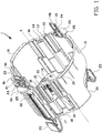
Figure 1 shows an isometric view of an installation box according to an embodiment of the invention without its strain relief insert; -
Figure 2A show an isometric view of an installation box with its strain relief insert according to an embodiment of the invention, and an exploded view of the installation box offigure 2A , respectively; -
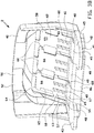
Figure 3A - 3B show isometric views of the strain relief insert as shown infigure 2B ; and -
Figure 4 shows an isometric view of the installation box offigure 1 with an electric wire or cable fastened thereto. -
Figure 1 shows aninstallation box 1 without itsstrain relief insert 2 being inserted therein according to an embodiment of the invention. Theinstallation box 1 comprises abottom wall 10 and a straight cylindricalcircumferential wall 11 with central axis S. Thecircumferential wall 11 has anupper edge 12 which bounds an installation opening of theinstallation box 1. Thebottom wall 10 and thecircumferential wall 11, which together confine an installation space, are made of plastic, in this example polypropylene, and form one rigid unity. - As best shown in
figure 1 , theinstallation box 1 comprises two opposite mountingplates 13 adjacent to theupper edge 12 in which mounting screws 14 are screwed. The mounting screws 14 extend through recessedchannels 15 behind the mountingplates 13. At the same locations and in circumferential direction also in between theinstallation box 1 is provided withslide couplings 16 on thecircumferential wall 11 to couplemultiple installation boxes 1 adjacent to each other in different configurations. Below theslide couplings 16, thecircumferential wall 11 is provided withsquare passages 17 that are closed off withbreakout ports 18 which are removed for electric wirings between the coupledinstallation boxes 1. Theinstallation box 1 is provided withfirst flanges 19 that form one unity with and that project from thecircumferential wall 11 to engage onto a non-shown front plate of a non-shown hollow wall. - The
installation box 1 is provided with two identical anchoring strips 20 for anchoring theinstallation box 1 in the front plate of the hollow wall. The anchoring strips 20 are located opposite to each other and in circumferential direction at 85 to 95 degrees with respect to the oppositefirst flanges 19 and at about 40 degrees with respect to the mounting screws 14. The anchoring strips 20 are made of a plastic with high tension strength, in particular POM (Polyoxymethylene), and comprise an elongategripping section 21 that rectilinearly continues into anelongate tensioning section 22. At the opposite end thetensioning section 22 is connected to ananchoring section 23. The grippingsection 21 comprises ahole 24 in the middle thereof for insertion of a pulling tool, such as a screwdriver. As best shown infigure 1 , theinstallation box 1 comprises twoguide channels 25 in thecircumferential wall 11 in which the anchoring strips 20 are received. The anchoring strips 20 are locked by means of barbed metal inserts 26. -
Figure 2A shows theinstallation box 1 in which thestrain relief insert 2 is inserted. Theinstallation box 1 is designed to be installed in a non-shown hollow wall of a building to install the electrical installation thereof. When theinstallation box 1 is inserted and secured into a circular hole in the front plate of the hollow wall, theinstallation box 1 is anchored by means of the anchoring strips 20. As schematically shown infigure 2B , thestrain relief insert 2 is configured for being installed in the longitudinal direction of the central axis S in the installation space and in particular at apassage opening 30 within thecircumferential wall 11 and thebottom wall 10. - As shown in
figure 1 apassage opening 30 is provided within thebottom wall 10 and thecircumferential wall 11 for receiving thestrain relief insert 2. Thepassage opening 30 includes a bottom wall opening 31 and acircumferential wall opening 32, which are merged into one another. The bottom wall opening 31 is bounded by abottom wall edge 33 and the circumferential wall opening 32 is bounded by acircumferential wall edge 34. - As shown in
figures 3A and3B thestrain relief insert 2 is provided with an insert body having awall part 40 and abottom part 41, preferably made of polypropylene. Thewall part 40 and thebottom part 41 are orientated substantially transversal to each other. Thebottom part 41 comprises abottom body 42 with anupper side 43 and alower side 44 opposite to theupper side 43. Aridge 45 is provided at thelower side 44 of thebottom body 42, whichridge 45 has afirst side 46 and asecond side 47. When thestrain relief insert 2 is inserted into theopening 30 of the installation box, a part of thelower side 44 of thebottom part 41 abuts on a surface of thebottom wall 10 of theinstallation box 1. Theridge 45 is positioned within the bottom wall opening 31, whereby thefirst side 46 of theridge 45 faces thebottom wall edge 33 and is complementary thereto. - As shown in
figures 3A and3B a number ofslots 48 are provided within thebottom body 42 near thewall part 40, whichslots 48 are parallel to and at a distance to each other. A number of connectingsegments 49 are defined by and between each pair ofslots 48, wherein the connectingsegments 49 define at least a part of thebottom wall edge 33. - The
wall part 40 includes awall body 50 having afirst side 51 and asecond side 52 opposite to thefirst side 51. Aninsert opening 53 is provided within thewall body 50 for at least one non-shown electric wire or cable to pass through thestrain relief insert 2. Theinsert opening 53 is bound by aninsert opening edge 54. As shown infigures 3A - 3B three strain relieving orcable retention members 55 are provided within theinsert opening 53 and substantially parallel to each other. Each of the strain relieving orcable retention members 55 comprises a strain relieving orcable retention body 56 having afirst side 57 and asecond side 58 opposite to thefirst side 57. Each of the strain relieving orcable retention members 55 is hingeably connected to one of the connectingsegments 49 by means of ahinge 59, in particular a livinghinge 59. The strain relieving orcable retention body 56 of each strain relieving orcable retention member 55 is secured to the openingedge 54 by means of one or more breakable securingelements 60, in particular breakable material bridges 60, extending between the strain relieving orcable retention body 56 and the openingedge 54. The strain relieving orcable retention members 55 are maintained in a closed position in which each of the strain relieving orcable retention members 55 blocks at least a part of theinsert opening 53, as best shown infigures 3A - 3B . - As shown in
figures 3A - 3B the strain relieving orcable retention body 56 of each of the strain relieving orcable retention members 55 includes afirst body part 61 and asecond body part 62. Thefirst body part 61 has a width W1 which is larger than a width W2 of thesecond body part 62. Thefirst body part 61 is provided with a first flange-shapedprotrusion 63 which partially extends around thefirst body part 61 as shown infigures 3A- 3B . The first flange-shapedprotrusion 63 is arranged where thefirst body part 61 and thesecond body part 62 meet. Thesecond body part 62 has a second flanged-shapedprotrusion 64 which partially extends around the circumference of thesecond body part 62 as shown infigures 3A - 3B . The second flange-shapedprotrusion 64 is arranged at thesecond side 58 of the strain relieving orcable retention member 56. At each strain relieving orcable retention member 55, a receivingspace 65, also called strain relieving or cable retention portion, is defined between and confined by the first and second flange-shapedprotrusions - As shown in
figure 3B each of the strain relieving orcable retention members 55 has acontact surface 66, which in the first position of the respective strain relieving orcable retention member 55 faces the installation space of theinstallation box 1. Thecontact surface 66 of each strain relieving orcable retention member 55 is configured for contacting a non-shown electric wire or cable inserted into theinstallation box 1. Afirst array 67 of teeth and asecond array 68 of teeth are arranged parallel to each other at thecontact surface 66 of each strain relieving orcable retention member 56. - As shown in
figure 3B thewall part 40 is provided with a firstcurved flange 70 and a secondcurved flange 71. The first andsecond flanges first side 51 of thewall body 50 of thewall part 40 and are arranged line symmetrical with respect to each other. When thestrain relief insert 2 is inserted into theinstallation box 1 and in particular at thepassage opening 30, the first andsecond flanges circumferential wall edge 34. As shown infigure 2A , thecircumferential wall edge 34 and the first andsecond flanges second flanges first latching cam 72 is provided at the respective end of the firstcurved flange 70 and asecond latching cam 73 is provided at the respective end of the secondcurved flange 71. The first andsecond latching cams first side 51 of thewall body 50 and beyond each of the first and secondcurved flanges strain relief insert 2 is inserted into theinstallation box 1 and in particular at thepassage opening 30, the first andsecond latching cams circumferential wall edge 34 in order to prevent thestrain relief insert 2 from being removed unintentionally from thepassage opening 30 and from being pushed unintentionally into the installation space of theinstallation box 1. As shown infigures 3A - 3B a pushing space or a pushing surface is defined between the first andsecond latching cams second latching cams strain relief insert 2 into the installation space of theinstallation box 1. - The
installation box 1 with itsstrain relief insert 2 inserted into the installation space thereof and an electric wire orcable 80 attached to a respective strain relieving orcable retention member 55 of thestrain relief insert 2 is shown infigure 4 . In order to attach the electric wire orcable 80 to the strain relieving orcable retention member 55, the one or more breakable securingelements 60 between the respective strain relieving orcable retention member 55 and the openingedge 54 of theinsert opening 53 are broken firstly. Secondly, the respective strain relieving orcable retention member 55 is moved from the closed position, as for example shown infigure 3A , to an open position, as shown infigure 4 . When the respective strain relieving orcable retention member 55 is in the open position, the respective strain relieving orcable retention member 55 is extending substantially parallel or parallel to an insert direction E of the electric wire orcable 80. Subsequently, the electric wire orcable 80 is placed at the respective strain relieving orcable retention member 55 and in particular placed against thecontact surface 66 of the respective strain relieving orcable retention member 55. As the electric wire orcable 80 is placed at thecontact surface 66, a part of the outer surface of the electric wire orcable 80 abuts on thefirst array 67 of teeth and thesecond array 68 of teeth. At last, afastener 81, for example a cable tie or a ty-rap, is placed around the electric wire orcable 80 and the strain relieving orcable retention member 55, and tightened for fastening the electric wire orcable 80 firmly to the respective strain relieving orcable retention member 55. By tightening thefastener 81 around the electric wire orcable 80 and the respective strain relieving orcable retention member 55, the electric wire orcable 80 is forced against thefirst array 67 of teeth and thesecond array 68 of teeth, such that the first andsecond array cable 80. - As shown in
figure 4 thefastener 81 is received within the receivingspace 65 defined between and confined by the first and second flange-shapedprotrusions cable 80 in a direction substantially parallel or parallel to the insert direction E, the pulling or pushing force is transferred, at least partially, to thestrain relief insert 2 due to thefastener 81 being tightened around the electric wire orcable 80 and the respective strain relieving orcable retention member 55. Because of thefastener 81 being fixated by the first and second flange-shapedprotrusions fastener 81 within the receivingspace 65 in a receiving direction I substantially parallel or parallel to the insert direction E is prevented or substantially prevented. Movement of thefastener 81 in the receiving direction I is counteracted by the first and second flange-shapedprotrusions fastener 81 in the receiving direction I due to a pulling force applied to the electric wire orcable 80 is delimited by the second flange-shapedprotrusion 64 and movement of thefastener 81 in the receiving direction I due to a pushing force applied to the electric wire orcable 80 is delimited by the first flange-shapedprotrusion 63. Additionally, any movement of the electric wire orcable 80 in the insert direction E or opposite thereto is counteracted, at least partially, by the first andsecond array cable 80 is forced by means of thefastener 81. Thestrain relief insert 2, therefore, provides a bi-directional (push and pull) strain relief for the electric wire orcable 80. - It is to be understood that the above description is included to illustrate the operation of the preferred embodiments and is not meant to limit the scope of the invention. From the above discussion, many variations will be apparent to one skilled in the art that would yet be encompassed by the scope of the present invention.
Claims (15)
- Assembly of an installation box (1) and electric installation material with at least one electric wire or cable (80), wherein the installation box comprises a housing with a bottom wall (10) and a circumferential wall (11) upright from the bottom wall (10), wherein the bottom wall (10) and the circumferential wall (11) together enclose an installation space for electric installation material, wherein an upper edge (12) of the circumferential wall (11) facing away from the bottom wall (10) bounds an installation opening for providing access to the installation space, wherein the circumferential wall (11) is provided with a passage opening (30) for the at least one electric wire or cable (80) to pass there through in an insert direction (E), characterized in that the installation box further comprises a strain relief or cable retention insert (2) inserted into the installation space and installed at the passage opening (30), wherein the strain relief or cable retention insert (2) is provided with a strain relieving or cable retention member (55) having a strain relieving or cable retention body (56) extending substantially parallel to the insert direction (E), and a fastener (81) for receiving and fastening the at least one electric wire or cable (80) to the strain relieving or cable retention member (55), wherein the fastener (81) surrounds the at least one electric wire or cable (80) and the strain relieving or cable retention member (55) .
- Assembly according to claim 1, wherein the strain relieving or cable retention member (55) further comprises a strain relieving or cable retention portion (63, 64, 65) configured for receiving at least a part of the fastener (81) and for substantially preventing movement of the fastener (81) in at least one direction substantially parallel to the insert direction (E), preferably wherein the strain relieving or cable retention portion (63, 64, 65) is configured for substantially fixating the fastener (81) to the strain relieving or cable retention member (55) .
- Assembly according to claim 1 or claim 2, wherein the strain relieving or cable retention portion comprises a first protrusion (63) extending substantially transversal to the insert direction (E) from the strain relieving or cable retention body (56), preferably wherein the strain relieving or cable retention portion comprises a second protrusion (64) extending substantially transversal to the insert direction (E) from the strain relieving or cable retention body (56), preferably wherein the second protrusion (64) is distanced from and/or parallel to the first protrusion (63).
- Assembly according to any one of the preceding claims, wherein the strain relief insert (2) further comprises an insert body (40, 41) having an insert opening defined therein, wherein the insert opening (53) is bounded by an insert opening edge (54) and the strain relieving or cable retention member (55) is connected to the insert body (40, 41).
- Assembly according to any one of the preceding claims, wherein the strain relieving or cable retention member (55) is moveable between a closed position, in which the strain relieving or cable retention member (55) blocks the passage opening (30) at least partially, and an open position, in which the strain relieving or cable retention member (55) extends substantially parallel to the insert direction (E).
- Assembly according to claim 4 and claim 5, wherein the strain relieving or cable retention body (56) has a first side (57) and a second side (58) opposite to the first side (57) in the longitudinal direction thereof, wherein the strain relieving or cable retention body (56) at the first side (57) thereof is hingeably connected to the insert opening edge (54), wherein when the strain relieving or cable retention member (55) is in the closed position, the strain relieving or cable retention member (55) at least partially blocks the insert opening (54).
- Assembly according to claim 6, wherein a hinge, preferably a living hinge (59), is provided between the strain relieving or cable retention body (56) and the insert opening edge (54) in order to connect to strain relieving or cable retention member (55) hingeably to the insert opening edge (54).
- Assembly according to claim 5, 6 or 7, further comprising one or more breakable securing elements (60) provided between and connected to the strain relieving or cable retention body (56) and the insert opening edge (54), when the strain relieving or cable retention member (55) is in the closed position, preferably wherein the one or more breakable securing elements (60) are breakable material bridges.
- Assembly according to any one of the preceding claims, wherein the strain relieving or cable retention body (56) has a contact surface (66) configured for contacting the electric wire or cable (80) fastened to the strain relieving or cable retention member (55), preferably wherein the contact surface (66_ is provided with friction elements (67; 68) for providing friction between the contact surface and the electric wire or cable fastened to the strain relieving or cable retention body.
- Assembly according to claim 9, wherein the friction elements (67; 68) comprise a first array (67) of teeth, wherein the first array (67) of teeth extends in a direction substantially parallel to the insert direction (E), preferably wherein the friction elements (67; 68) comprise a second array (68) of teeth parallel to the first array (67) of teeth.
- Assembly according to any one of the preceding claims, when dependent on claim 4, wherein a first flange (70) and a second flange (71) are provided at a first side (51) of the insert body (40, 41), preferably line symmetrical to each other, and projecting from the first side (51), preferably wherein the first and second flanges (70; 71) are complementary to at least a part of a passage opening edge (33, 34) bounding the passage opening (30).
- Assembly according to any one of the preceding claims, when dependent on claim 4, wherein the insert body (40, 41) is provided with at least a first latching cam (72) adapted for latching the strain relief insert (2) within the installation space and at the passage opening (30), preferably wherein the first latching cam (71) projects from a first side (51) of the insert body (40, 41) and faces a passage opening edge (33, 34) bounding the passage opening (30).
- Assembly according to any one of the preceding claims, wherein the strain relief insert (2) comprises two or more, preferably three or more strain relief members (55), preferably wherein the strain relief members (55) are arranged substantially parallel to each other.
- Strain relief insert (2) for use in an assembly according to any one of the preceding claims.
- Method for installing an electric wire or cable (80) in an installation box (1), wherein the installation box comprises a housing with a bottom wall (10) and a circumferential wall (11) upright from the bottom wall (10), wherein the bottom wall (10) and the circumferential wall (11) together enclose an installation space for electric installation material, wherein an upper edge (12) of the circumferential wall (11) facing away from the bottom wall (10) bounds an installation opening for providing access to the installation space, wherein the circumferential wall (11) is provided with a passage opening (30) for at least one electric wire or cable (80) to pass there through in an insert direction (E), the installation box (1) further comprising a strain relief insert (2) inserted into the installation space and installed at the passage opening (30), wherein the strain relief insert (2) is provided with a strain relieving or cable retention member (55) having a strain relieving or cable retention body (56) extending substantially parallel to the insert direction (E), and a fastener (81) for receiving and fastening at least one electric wire or cable (80) to the strain relieving or cable retention member (55), wherein the method comprises the steps of:- inserting an electric wire or cable (80) into the installation space of the installation box (1); and- optionally, connecting the electric wire or cable (80) to electric installation material within the installation space of the installation box (1) ; wherein the method is characterized by the steps of:- placing the electric wire or cable (80) against the strain relieving or cable retention member (55) of the strain relief insert (2); and- fastening the electric wire or cable (80) to the strain relieving or cable retention member (55) by surrounding the electric wire or cable (80) and the strain relieving or cable retention member (55) by a fastener (81) and tightening the fastener (81).
Applications Claiming Priority (1)
| Application Number | Priority Date | Filing Date | Title |
|---|---|---|---|
| EP18158570 | 2018-02-26 |
Publications (2)
| Publication Number | Publication Date |
|---|---|
| EP3531520A1 true EP3531520A1 (en) | 2019-08-28 |
| EP3531520B1 EP3531520B1 (en) | 2021-03-24 |
Family
ID=61283063
Family Applications (1)
| Application Number | Title | Priority Date | Filing Date |
|---|---|---|---|
| EP18178999.1A Active EP3531520B1 (en) | 2018-02-26 | 2018-06-21 | Assembly of an installation box and electric installation material, and strain relief insert |
Country Status (2)
| Country | Link |
|---|---|
| EP (1) | EP3531520B1 (en) |
| DK (1) | DK3531520T3 (en) |
Cited By (1)
| Publication number | Priority date | Publication date | Assignee | Title |
|---|---|---|---|---|
| WO2025040300A1 (en) * | 2023-08-24 | 2025-02-27 | Stellantis Auto Sas | Electrical junction box, battery module and vehicle |
Citations (7)
| Publication number | Priority date | Publication date | Assignee | Title |
|---|---|---|---|---|
| US4277641A (en) * | 1979-09-26 | 1981-07-07 | Gte Products Corporation | Electrical outlet box and cable clamp device |
| US4389535A (en) * | 1978-02-21 | 1983-06-21 | Slater Electric Inc. | Cable entry port means for electrical outlet box |
| DE202010006582U1 (en) * | 2010-05-07 | 2010-08-05 | CCS Technology, Inc., Wilmington | Inline cable sleeve |
| EP2472685A1 (en) * | 2010-12-29 | 2012-07-04 | Abb B.V. | Hollow wall box with fire resistant insert piece |
| EP2520959A1 (en) * | 2011-05-05 | 2012-11-07 | CCS Technology, Inc. | Cable strain relief device for cable closures and cable closure having at least one such cable strain relief device |
| DE202012101639U1 (en) * | 2012-05-03 | 2013-08-06 | Weidmüller Interface GmbH & Co. KG | Through housing |
| US20160238160A1 (en) * | 2015-02-17 | 2016-08-18 | Hubbell Incorporated | Enclosure assemblies having cable clamping inserts and cable clamping inserts for such enclosures |
-
2018
- 2018-06-21 EP EP18178999.1A patent/EP3531520B1/en active Active
- 2018-06-21 DK DK18178999.1T patent/DK3531520T3/en active
Patent Citations (7)
| Publication number | Priority date | Publication date | Assignee | Title |
|---|---|---|---|---|
| US4389535A (en) * | 1978-02-21 | 1983-06-21 | Slater Electric Inc. | Cable entry port means for electrical outlet box |
| US4277641A (en) * | 1979-09-26 | 1981-07-07 | Gte Products Corporation | Electrical outlet box and cable clamp device |
| DE202010006582U1 (en) * | 2010-05-07 | 2010-08-05 | CCS Technology, Inc., Wilmington | Inline cable sleeve |
| EP2472685A1 (en) * | 2010-12-29 | 2012-07-04 | Abb B.V. | Hollow wall box with fire resistant insert piece |
| EP2520959A1 (en) * | 2011-05-05 | 2012-11-07 | CCS Technology, Inc. | Cable strain relief device for cable closures and cable closure having at least one such cable strain relief device |
| DE202012101639U1 (en) * | 2012-05-03 | 2013-08-06 | Weidmüller Interface GmbH & Co. KG | Through housing |
| US20160238160A1 (en) * | 2015-02-17 | 2016-08-18 | Hubbell Incorporated | Enclosure assemblies having cable clamping inserts and cable clamping inserts for such enclosures |
Cited By (1)
| Publication number | Priority date | Publication date | Assignee | Title |
|---|---|---|---|---|
| WO2025040300A1 (en) * | 2023-08-24 | 2025-02-27 | Stellantis Auto Sas | Electrical junction box, battery module and vehicle |
Also Published As
| Publication number | Publication date |
|---|---|
| DK3531520T3 (en) | 2021-06-21 |
| EP3531520B1 (en) | 2021-03-24 |
Similar Documents
| Publication | Publication Date | Title |
|---|---|---|
| US7118413B2 (en) | Quick assembling electrical connection box apparatus and method | |
| US7019211B2 (en) | Universal junction box | |
| USRE47893E1 (en) | Conduit connector and methods for making and using the same | |
| US4954667A (en) | Electrical box with coupling members | |
| US6679725B2 (en) | Clip-on cover plate for electrical fixtures | |
| CA2582792C (en) | Quick insert clamp for metal boxes | |
| US5118057A (en) | Cable fitting | |
| US20130157491A1 (en) | Conduit connector and methods for making and using the same | |
| US6840800B2 (en) | Deflecting securement anchor for electrical fixtures | |
| US7306482B1 (en) | Electrical connection box | |
| US4724282A (en) | Electrical box | |
| US10644491B2 (en) | Electrical box cable connector | |
| US6177633B1 (en) | Cable connector | |
| CN102474039A (en) | Sealing member | |
| US20100307039A1 (en) | Identification device for electrical conductors | |
| US7342173B1 (en) | Multi-directional-port junction box | |
| US5908180A (en) | Symmetrical cable bracketing and strain relieving mechanism and method | |
| EP3531520B1 (en) | Assembly of an installation box and electric installation material, and strain relief insert | |
| US7083467B2 (en) | Connection box stabilizer | |
| US7077695B2 (en) | Clip-on face plate for electrical fixtures | |
| EP1113552A1 (en) | Cable channel with inwardly projecting parts for passing through ties | |
| CA3037479C (en) | Clip-based non-metallic fittings for attachment of flexible metallic conduit | |
| JP2023532892A (en) | junction assembly | |
| US7151220B1 (en) | Fast set screw device for non-metallic boxes | |
| WO2023110568A1 (en) | Connector |
Legal Events
| Date | Code | Title | Description |
|---|---|---|---|
| PUAI | Public reference made under article 153(3) epc to a published international application that has entered the european phase |
Free format text: ORIGINAL CODE: 0009012 |
|
| STAA | Information on the status of an ep patent application or granted ep patent |
Free format text: STATUS: REQUEST FOR EXAMINATION WAS MADE |
|
| 17P | Request for examination filed |
Effective date: 20180621 |
|
| AK | Designated contracting states |
Kind code of ref document: A1 Designated state(s): AL AT BE BG CH CY CZ DE DK EE ES FI FR GB GR HR HU IE IS IT LI LT LU LV MC MK MT NL NO PL PT RO RS SE SI SK SM TR |
|
| AX | Request for extension of the european patent |
Extension state: BA ME |
|
| STAA | Information on the status of an ep patent application or granted ep patent |
Free format text: STATUS: EXAMINATION IS IN PROGRESS |
|
| 17Q | First examination report despatched |
Effective date: 20200107 |
|
| RAP1 | Party data changed (applicant data changed or rights of an application transferred) |
Owner name: ABB SCHWEIZ AG |
|
| GRAP | Despatch of communication of intention to grant a patent |
Free format text: ORIGINAL CODE: EPIDOSNIGR1 |
|
| STAA | Information on the status of an ep patent application or granted ep patent |
Free format text: STATUS: GRANT OF PATENT IS INTENDED |
|
| RIC1 | Information provided on ipc code assigned before grant |
Ipc: H02G 3/12 20060101ALN20200924BHEP Ipc: H02G 15/007 20060101ALN20200924BHEP Ipc: H02G 3/06 20060101ALN20200924BHEP Ipc: H02G 3/08 20060101AFI20200924BHEP |
|
| INTG | Intention to grant announced |
Effective date: 20201012 |
|
| GRAS | Grant fee paid |
Free format text: ORIGINAL CODE: EPIDOSNIGR3 |
|
| GRAA | (expected) grant |
Free format text: ORIGINAL CODE: 0009210 |
|
| STAA | Information on the status of an ep patent application or granted ep patent |
Free format text: STATUS: THE PATENT HAS BEEN GRANTED |
|
| AK | Designated contracting states |
Kind code of ref document: B1 Designated state(s): AL AT BE BG CH CY CZ DE DK EE ES FI FR GB GR HR HU IE IS IT LI LT LU LV MC MK MT NL NO PL PT RO RS SE SI SK SM TR |
|
| REG | Reference to a national code |
Ref country code: GB Ref legal event code: FG4D |
|
| REG | Reference to a national code |
Ref country code: CH Ref legal event code: EP |
|
| REG | Reference to a national code |
Ref country code: DE Ref legal event code: R096 Ref document number: 602018014250 Country of ref document: DE |
|
| REG | Reference to a national code |
Ref country code: SE Ref legal event code: TRGR |
|
| REG | Reference to a national code |
Ref country code: IE Ref legal event code: FG4D |
|
| REG | Reference to a national code |
Ref country code: AT Ref legal event code: REF Ref document number: 1375472 Country of ref document: AT Kind code of ref document: T Effective date: 20210415 |
|
| REG | Reference to a national code |
Ref country code: DK Ref legal event code: T3 Effective date: 20210617 |
|
| REG | Reference to a national code |
Ref country code: NL Ref legal event code: FP |
|
| REG | Reference to a national code |
Ref country code: LT Ref legal event code: MG9D |
|
| PG25 | Lapsed in a contracting state [announced via postgrant information from national office to epo] |
Ref country code: BG Free format text: LAPSE BECAUSE OF FAILURE TO SUBMIT A TRANSLATION OF THE DESCRIPTION OR TO PAY THE FEE WITHIN THE PRESCRIBED TIME-LIMIT Effective date: 20210624 Ref country code: FI Free format text: LAPSE BECAUSE OF FAILURE TO SUBMIT A TRANSLATION OF THE DESCRIPTION OR TO PAY THE FEE WITHIN THE PRESCRIBED TIME-LIMIT Effective date: 20210324 Ref country code: GR Free format text: LAPSE BECAUSE OF FAILURE TO SUBMIT A TRANSLATION OF THE DESCRIPTION OR TO PAY THE FEE WITHIN THE PRESCRIBED TIME-LIMIT Effective date: 20210625 Ref country code: HR Free format text: LAPSE BECAUSE OF FAILURE TO SUBMIT A TRANSLATION OF THE DESCRIPTION OR TO PAY THE FEE WITHIN THE PRESCRIBED TIME-LIMIT Effective date: 20210324 Ref country code: NO Free format text: LAPSE BECAUSE OF FAILURE TO SUBMIT A TRANSLATION OF THE DESCRIPTION OR TO PAY THE FEE WITHIN THE PRESCRIBED TIME-LIMIT Effective date: 20210624 |
|
| PG25 | Lapsed in a contracting state [announced via postgrant information from national office to epo] |
Ref country code: RS Free format text: LAPSE BECAUSE OF FAILURE TO SUBMIT A TRANSLATION OF THE DESCRIPTION OR TO PAY THE FEE WITHIN THE PRESCRIBED TIME-LIMIT Effective date: 20210324 Ref country code: LV Free format text: LAPSE BECAUSE OF FAILURE TO SUBMIT A TRANSLATION OF THE DESCRIPTION OR TO PAY THE FEE WITHIN THE PRESCRIBED TIME-LIMIT Effective date: 20210324 |
|
| REG | Reference to a national code |
Ref country code: AT Ref legal event code: MK05 Ref document number: 1375472 Country of ref document: AT Kind code of ref document: T Effective date: 20210324 |
|
| PG25 | Lapsed in a contracting state [announced via postgrant information from national office to epo] |
Ref country code: SM Free format text: LAPSE BECAUSE OF FAILURE TO SUBMIT A TRANSLATION OF THE DESCRIPTION OR TO PAY THE FEE WITHIN THE PRESCRIBED TIME-LIMIT Effective date: 20210324 Ref country code: AT Free format text: LAPSE BECAUSE OF FAILURE TO SUBMIT A TRANSLATION OF THE DESCRIPTION OR TO PAY THE FEE WITHIN THE PRESCRIBED TIME-LIMIT Effective date: 20210324 Ref country code: LT Free format text: LAPSE BECAUSE OF FAILURE TO SUBMIT A TRANSLATION OF THE DESCRIPTION OR TO PAY THE FEE WITHIN THE PRESCRIBED TIME-LIMIT Effective date: 20210324 Ref country code: CZ Free format text: LAPSE BECAUSE OF FAILURE TO SUBMIT A TRANSLATION OF THE DESCRIPTION OR TO PAY THE FEE WITHIN THE PRESCRIBED TIME-LIMIT Effective date: 20210324 Ref country code: EE Free format text: LAPSE BECAUSE OF FAILURE TO SUBMIT A TRANSLATION OF THE DESCRIPTION OR TO PAY THE FEE WITHIN THE PRESCRIBED TIME-LIMIT Effective date: 20210324 |
|
| PG25 | Lapsed in a contracting state [announced via postgrant information from national office to epo] |
Ref country code: SK Free format text: LAPSE BECAUSE OF FAILURE TO SUBMIT A TRANSLATION OF THE DESCRIPTION OR TO PAY THE FEE WITHIN THE PRESCRIBED TIME-LIMIT Effective date: 20210324 Ref country code: RO Free format text: LAPSE BECAUSE OF FAILURE TO SUBMIT A TRANSLATION OF THE DESCRIPTION OR TO PAY THE FEE WITHIN THE PRESCRIBED TIME-LIMIT Effective date: 20210324 Ref country code: PT Free format text: LAPSE BECAUSE OF FAILURE TO SUBMIT A TRANSLATION OF THE DESCRIPTION OR TO PAY THE FEE WITHIN THE PRESCRIBED TIME-LIMIT Effective date: 20210726 Ref country code: PL Free format text: LAPSE BECAUSE OF FAILURE TO SUBMIT A TRANSLATION OF THE DESCRIPTION OR TO PAY THE FEE WITHIN THE PRESCRIBED TIME-LIMIT Effective date: 20210324 Ref country code: IS Free format text: LAPSE BECAUSE OF FAILURE TO SUBMIT A TRANSLATION OF THE DESCRIPTION OR TO PAY THE FEE WITHIN THE PRESCRIBED TIME-LIMIT Effective date: 20210724 |
|
| REG | Reference to a national code |
Ref country code: DE Ref legal event code: R097 Ref document number: 602018014250 Country of ref document: DE |
|
| PG25 | Lapsed in a contracting state [announced via postgrant information from national office to epo] |
Ref country code: ES Free format text: LAPSE BECAUSE OF FAILURE TO SUBMIT A TRANSLATION OF THE DESCRIPTION OR TO PAY THE FEE WITHIN THE PRESCRIBED TIME-LIMIT Effective date: 20210324 Ref country code: AL Free format text: LAPSE BECAUSE OF FAILURE TO SUBMIT A TRANSLATION OF THE DESCRIPTION OR TO PAY THE FEE WITHIN THE PRESCRIBED TIME-LIMIT Effective date: 20210324 Ref country code: MC Free format text: LAPSE BECAUSE OF FAILURE TO SUBMIT A TRANSLATION OF THE DESCRIPTION OR TO PAY THE FEE WITHIN THE PRESCRIBED TIME-LIMIT Effective date: 20210324 |
|
| REG | Reference to a national code |
Ref country code: CH Ref legal event code: PL |
|
| PLBE | No opposition filed within time limit |
Free format text: ORIGINAL CODE: 0009261 |
|
| STAA | Information on the status of an ep patent application or granted ep patent |
Free format text: STATUS: NO OPPOSITION FILED WITHIN TIME LIMIT |
|
| PG25 | Lapsed in a contracting state [announced via postgrant information from national office to epo] |
Ref country code: SI Free format text: LAPSE BECAUSE OF FAILURE TO SUBMIT A TRANSLATION OF THE DESCRIPTION OR TO PAY THE FEE WITHIN THE PRESCRIBED TIME-LIMIT Effective date: 20210324 |
|
| 26N | No opposition filed |
Effective date: 20220104 |
|
| REG | Reference to a national code |
Ref country code: BE Ref legal event code: MM Effective date: 20210630 |
|
| PG25 | Lapsed in a contracting state [announced via postgrant information from national office to epo] |
Ref country code: LU Free format text: LAPSE BECAUSE OF NON-PAYMENT OF DUE FEES Effective date: 20210621 |
|
| PG25 | Lapsed in a contracting state [announced via postgrant information from national office to epo] |
Ref country code: LI Free format text: LAPSE BECAUSE OF NON-PAYMENT OF DUE FEES Effective date: 20210630 Ref country code: IE Free format text: LAPSE BECAUSE OF NON-PAYMENT OF DUE FEES Effective date: 20210621 Ref country code: CH Free format text: LAPSE BECAUSE OF NON-PAYMENT OF DUE FEES Effective date: 20210630 |
|
| PG25 | Lapsed in a contracting state [announced via postgrant information from national office to epo] |
Ref country code: IS Free format text: LAPSE BECAUSE OF FAILURE TO SUBMIT A TRANSLATION OF THE DESCRIPTION OR TO PAY THE FEE WITHIN THE PRESCRIBED TIME-LIMIT Effective date: 20210724 Ref country code: FR Free format text: LAPSE BECAUSE OF NON-PAYMENT OF DUE FEES Effective date: 20210630 |
|
| PG25 | Lapsed in a contracting state [announced via postgrant information from national office to epo] |
Ref country code: BE Free format text: LAPSE BECAUSE OF NON-PAYMENT OF DUE FEES Effective date: 20210630 |
|
| PG25 | Lapsed in a contracting state [announced via postgrant information from national office to epo] |
Ref country code: IT Free format text: LAPSE BECAUSE OF FAILURE TO SUBMIT A TRANSLATION OF THE DESCRIPTION OR TO PAY THE FEE WITHIN THE PRESCRIBED TIME-LIMIT Effective date: 20210324 |
|
| GBPC | Gb: european patent ceased through non-payment of renewal fee |
Effective date: 20220621 |
|
| PG25 | Lapsed in a contracting state [announced via postgrant information from national office to epo] |
Ref country code: GB Free format text: LAPSE BECAUSE OF NON-PAYMENT OF DUE FEES Effective date: 20220621 |
|
| PG25 | Lapsed in a contracting state [announced via postgrant information from national office to epo] |
Ref country code: CY Free format text: LAPSE BECAUSE OF FAILURE TO SUBMIT A TRANSLATION OF THE DESCRIPTION OR TO PAY THE FEE WITHIN THE PRESCRIBED TIME-LIMIT Effective date: 20210324 |
|
| PG25 | Lapsed in a contracting state [announced via postgrant information from national office to epo] |
Ref country code: HU Free format text: LAPSE BECAUSE OF FAILURE TO SUBMIT A TRANSLATION OF THE DESCRIPTION OR TO PAY THE FEE WITHIN THE PRESCRIBED TIME-LIMIT; INVALID AB INITIO Effective date: 20180621 |
|
| PG25 | Lapsed in a contracting state [announced via postgrant information from national office to epo] |
Ref country code: MK Free format text: LAPSE BECAUSE OF FAILURE TO SUBMIT A TRANSLATION OF THE DESCRIPTION OR TO PAY THE FEE WITHIN THE PRESCRIBED TIME-LIMIT Effective date: 20210324 |
|
| PG25 | Lapsed in a contracting state [announced via postgrant information from national office to epo] |
Ref country code: MT Free format text: LAPSE BECAUSE OF FAILURE TO SUBMIT A TRANSLATION OF THE DESCRIPTION OR TO PAY THE FEE WITHIN THE PRESCRIBED TIME-LIMIT Effective date: 20210324 |
|
| PGFP | Annual fee paid to national office [announced via postgrant information from national office to epo] |
Ref country code: DE Payment date: 20250618 Year of fee payment: 8 |
|
| PGFP | Annual fee paid to national office [announced via postgrant information from national office to epo] |
Ref country code: DK Payment date: 20250625 Year of fee payment: 8 |
|
| PGFP | Annual fee paid to national office [announced via postgrant information from national office to epo] |
Ref country code: NL Payment date: 20250618 Year of fee payment: 8 |
|
| PGFP | Annual fee paid to national office [announced via postgrant information from national office to epo] |
Ref country code: SE Payment date: 20250618 Year of fee payment: 8 |
|
| PG25 | Lapsed in a contracting state [announced via postgrant information from national office to epo] |
Ref country code: TR Free format text: LAPSE BECAUSE OF FAILURE TO SUBMIT A TRANSLATION OF THE DESCRIPTION OR TO PAY THE FEE WITHIN THE PRESCRIBED TIME-LIMIT Effective date: 20210324 |