EP3531233A1 - Coupling mechanism for coupling electronic device - Google Patents
Coupling mechanism for coupling electronic device Download PDFInfo
- Publication number
- EP3531233A1 EP3531233A1 EP19158107.3A EP19158107A EP3531233A1 EP 3531233 A1 EP3531233 A1 EP 3531233A1 EP 19158107 A EP19158107 A EP 19158107A EP 3531233 A1 EP3531233 A1 EP 3531233A1
- Authority
- EP
- European Patent Office
- Prior art keywords
- bracket
- stopper
- hook
- electronic device
- outer casing
- Prior art date
- Legal status (The legal status is an assumption and is not a legal conclusion. Google has not performed a legal analysis and makes no representation as to the accuracy of the status listed.)
- Granted
Links
Images


Classifications
-
- G—PHYSICS
- G06—COMPUTING OR CALCULATING; COUNTING
- G06F—ELECTRIC DIGITAL DATA PROCESSING
- G06F1/00—Details not covered by groups G06F3/00 - G06F13/00 and G06F21/00
- G06F1/16—Constructional details or arrangements
- G06F1/1613—Constructional details or arrangements for portable computers
- G06F1/1626—Constructional details or arrangements for portable computers with a single-body enclosure integrating a flat display, e.g. Personal Digital Assistants [PDAs]
-
- G—PHYSICS
- G06—COMPUTING OR CALCULATING; COUNTING
- G06F—ELECTRIC DIGITAL DATA PROCESSING
- G06F1/00—Details not covered by groups G06F3/00 - G06F13/00 and G06F21/00
- G06F1/16—Constructional details or arrangements
- G06F1/18—Packaging or power distribution
- G06F1/183—Internal mounting support structures, e.g. for supporting printed circuit boards
-
- H—ELECTRICITY
- H05—ELECTRIC TECHNIQUES NOT OTHERWISE PROVIDED FOR
- H05K—PRINTED CIRCUITS; CASINGS OR CONSTRUCTIONAL DETAILS OF ELECTRIC APPARATUS; MANUFACTURE OF ASSEMBLAGES OF ELECTRICAL COMPONENTS
- H05K7/00—Constructional details common to different types of electric apparatus
- H05K7/14—Mounting supporting structure in casing or on frame or rack
- H05K7/1401—Mounting supporting structure in casing or on frame or rack comprising clamping or extracting means
-
- G—PHYSICS
- G06—COMPUTING OR CALCULATING; COUNTING
- G06F—ELECTRIC DIGITAL DATA PROCESSING
- G06F1/00—Details not covered by groups G06F3/00 - G06F13/00 and G06F21/00
- G06F1/16—Constructional details or arrangements
- G06F1/1601—Constructional details related to the housing of computer displays, e.g. of CRT monitors, of flat displays
- G06F1/1607—Arrangements to support accessories mechanically attached to the display housing
-
- G—PHYSICS
- G06—COMPUTING OR CALCULATING; COUNTING
- G06F—ELECTRIC DIGITAL DATA PROCESSING
- G06F1/00—Details not covered by groups G06F3/00 - G06F13/00 and G06F21/00
- G06F1/16—Constructional details or arrangements
- G06F1/1613—Constructional details or arrangements for portable computers
- G06F1/1633—Constructional details or arrangements of portable computers not specific to the type of enclosures covered by groups G06F1/1615 - G06F1/1626
-
- H—ELECTRICITY
- H02—GENERATION; CONVERSION OR DISTRIBUTION OF ELECTRIC POWER
- H02B—BOARDS, SUBSTATIONS OR SWITCHING ARRANGEMENTS FOR THE SUPPLY OR DISTRIBUTION OF ELECTRIC POWER
- H02B1/00—Frameworks, boards, panels, desks, casings; Details of substations or switching arrangements
-
- H—ELECTRICITY
- H05—ELECTRIC TECHNIQUES NOT OTHERWISE PROVIDED FOR
- H05K—PRINTED CIRCUITS; CASINGS OR CONSTRUCTIONAL DETAILS OF ELECTRIC APPARATUS; MANUFACTURE OF ASSEMBLAGES OF ELECTRICAL COMPONENTS
- H05K5/00—Casings, cabinets or drawers for electric apparatus
- H05K5/02—Details
- H05K5/0208—Interlock mechanisms; Means for avoiding unauthorised use or function, e.g. tamperproof
-
- H—ELECTRICITY
- H05—ELECTRIC TECHNIQUES NOT OTHERWISE PROVIDED FOR
- H05K—PRINTED CIRCUITS; CASINGS OR CONSTRUCTIONAL DETAILS OF ELECTRIC APPARATUS; MANUFACTURE OF ASSEMBLAGES OF ELECTRICAL COMPONENTS
- H05K5/00—Casings, cabinets or drawers for electric apparatus
- H05K5/02—Details
- H05K5/0217—Mechanical details of casings
-
- G—PHYSICS
- G06—COMPUTING OR CALCULATING; COUNTING
- G06F—ELECTRIC DIGITAL DATA PROCESSING
- G06F2200/00—Indexing scheme relating to G06F1/04 - G06F1/32
- G06F2200/16—Indexing scheme relating to G06F1/16 - G06F1/18
- G06F2200/163—Indexing scheme relating to constructional details of the computer
- G06F2200/1631—Panel PC, e.g. single housing hosting PC and display panel
Definitions
- the present disclosure relates to a coupling mechanism capable of pre-coupling an electronic device to an outer casing so that the outer casing and the electronic device are not separated from each other before the electronic device is completely mounted on the outer casing.
- a HMI (Human Machine Interface) device or panel PC means a multifunctional control device in a form of a panel excluding integrated mechanical elements such as a hard disk, a CD driver, a cooling fan, etc. such that the device may be easily used by a field worker.
- the HMI device is provided in various forms including a fixed panel form in which the device may be fixed to a panel and a removable panel form in which the operator removes the device from the panel.
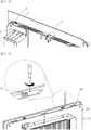
- FIG. 1 shows a conventional coupling structure for an electronic device.
- FIG. 2 shows another conventional coupling structure for an electronic device.
- an operator when installing an electronic device 5 such as an HMI device or panel PC, an operator first inserts the electronic device 5 into a mounting hole 2 defined in an outer casing 1. Thereafter, a hook-shaped bracket 7 formed on the electronic device 5 is hooked into the outer casing 1. Thus, the electronic device 5 may be prevented from being separated from the outer casing 1.
- the bracket 7 is made of plastic.
- the hook-shaped portion passes through a hole defined in a front cover or rear cover of the electronic device 5 and is inserted into the hole 2 and caught into the outer casing 1. Further, the front or rear cover is detachable.
- An unexposed portion of the bracket 7 may be typically composed of 3 to 5 coupling parts such as springs, pins, and the like.
- a bracket 7' having a plurality of hooks is mounted between a front cover 5a or a rear cover 5b. Then, the front cover 5a and the rear cover 5b are coupled with each other via separate fastening bolts. The electronic device 5' is then installed onto the outer casing 1. In this case, a construction and material of the bracket 7' are the same as in FIG. 1 .
- the conventional bracket for the electronic device is made of a plastic material, there is a risk that the hook-shaped portion of the bracket is bent or broken when the bracket is inserted into the mounting hole in the outer casing. Since the hook-shaped bracket is composed of the 3 to 5 parts, the assembling process is complicated and the cost of the bracket is increased.
- a purpose of the present disclosure is to provide a coupling mechanism for coupling an electronic device to an outer casing by which one operator can easily mount the electronic device into the outer casing.
- Another purpose of the present disclosure is to provide a coupling mechanism for coupling an electronic device to an outer casing in which a structure of a bracket is improved to reduce a cost and to simplify an assembly process and to reduce an assembly time.
- a coupling mechanism for coupling an electronic device to an outer casing, wherein the outer casing has an accommodation hole defined therein sized to correspond to a size of the electronic device, wherein the electronic device includes a front cover exposed out of the outer casing, and a rear cover coupled to a rear of the front cover
- the coupling mechanism comprising: a plurality of hook-shaped brackets interposed between the front and rear covers and wherein the plurality of hook-shaped brackets pass through the accommodation hole and are held to hook the outer casing while the front cover and the rear cover are coupled to each other; a plurality of main bracket-mounted portion defined in the front cover wherein each hook-shaped bracket is mounted into each main bracket-mounted portion; and a plurality of auxiliary bracket-mounted portion disposed on the rear cover wherein each auxiliary bracket-mounted portion is engaged with each hook-shaped bracket when the front cover and the rear cover are coupled to each other.
- each hook-shaped bracket includes: a hooking portion held to hook the outer casing; a bracket body having the same width as the hooking portion and extending horizontally from one end of the hooking portion; first stoppers a integrally formed with the bracket body at both opposing sides thereof; and a second stopper vertically extending and then horizontally extending from one end of the bracket body and such that the second stopper faces away the bracket body.
- the hook-shaped bracket is made of rigid metal, wherein when the electronic device is inserted into the accommodation hole, the hooking portion and the bracket body are pressed and elastically deformed, wherein after the electronic device has been inserted into the accommodation hole, the hooking portion and the bracket body are elastically restored such that the hooking portion is held to hook the outer casing.
- each main bracket-mounted portion includes: a bracket-mounted groove defined in a second frame, wherein the second frame is coupled to a first frame along an edge thereof, wherein the first frame is coupled to a front face of the front cover wherein the groove is open toward the outer casing; both first ribs and both second ribs integrally formed with the second frame, wherein a receiving space for receiving the hook-shaped bracket is defined between the both first ribs and both second ribs.
- the bracket-mounted groove has a width corresponding to a width of the hooking portion, wherein each of the first ribs includes an elongate bar, wherein the bar protrudes from an inner face of the second frame, wherein the bracket body are disposed between the bars of the first ribs, wherein each of the second ribs includes an elongate bar, wherein the bar protrudes from the inner face of the second frame, wherein each first stopper a and each second stopper are disposed between each first rib and each second rib, wherein each second rib is disposed below each first rib.
- the first stopper a vertically downwardly extends and then horizontally outwardly extends from the bracket body, wherein the first stopper a has a horizontal dimension equal to a horizontal dimension of the first rib, wherein the first stopper a is in close contact with the first rib, wherein the second stopper is in close contact with the second rib.
- the hook-shaped bracket includes a third stopper extending vertically downwardly from a distal end of the second stopper, wherein the auxiliary bracket-mounted portion protrudes in a plate form from an inner face of the rear cover and at a position corresponding to a position of the main bracket-mounted portion, wherein the auxiliary bracket-mounted portion contacts and presses against the third stopper when the front cover and the rear cover are coupled to each other.
- the second stopper has a horizontal portion branching into a U shape, wherein each third stopper is formed at a distal end of each of prongs of the U shape.
- the second stopper has a horizontal portion having a width greater than a width of the bracket body, wherein the third stopper is formed at a distal end of the second stopper.
- each first stopper has a 90-degree rotated U shaped cross section such that the first stopper wraps the first rib.
- manufacturing the coupling mechanism for coupling the electronic device with a rigid material may allow the mechanism production cost to be reduced, and allow installation convenience of the device and durability of the mechanism to be improved. Further, improving the structure of the coupling mechanism may allow the electronic device to be installed by only one operator and may shorten the assembly time.
- first element or layer when a first element or layer is referred to as being present "on" a second element or layer, the first element may be disposed directly on the second element or may be disposed indirectly on the second element with a third element or layer being disposed between the first and second elements or layers. It will be understood that when an element or layer is referred to as being “connected to”, or “coupled to” another element or layer, it can be directly on, connected to, or coupled to the other element or layer, or one or more intervening elements or layers may be present. In addition, it will also be understood that when an element or layer is referred to as being “between” two elements or layers, it can be the only element or layer between the two elements or layers, or one or more intervening elements or layers may also be present.
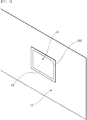
- FIG. 3 is a front view showing an electronic device mounted on an outer casing.
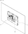
- FIG. 4 is a back view showing the electronic device mounted on the outer casing. The figures show only a portion of the outer casing.
- an electronic device 30 includes an HMI device or a panel PC, and has a panel shape having a predetermined thickness.
- the electronic device 30 may be installed into an separate outer casing 10.
- the outer casing 10 has an accommodation hole 12 defined therein having a size corresponding to a size of the electronic device 30.
- the electronic device 30 has a front portion exposed to an outside from a front of the outer casing 10 and a rear portion corresponding to a rear of the outer casing 10.
- the electronic device 30 may include a front cover 100 that covers a portion of the front portion and a rear cover 300 that covers partially or entirely the rear portion.
- the front cover 100 covers and supports an edge of the front portion of the electronic device 30.
- the front portion may be composed of, for example, a display on which an image is displayed.
- the front cover 100 has a shape that surrounds an edge of the display.
- a portion of the front cover exposed out of the outer casing 10 may be defined as a front portion of the front cover.
- a face of the front cover 100 facing forwardly may be defined as a front face thereof.
- a portion of the front cover facing rearwardly may be defined as a rear portion of the front cover.
- a face of the front cover 100 facing rearwardly may be defined as a rear face thereof.
- FIG. 3 shows a front face of the outer casing 10
- FIG. 4 shows a rear face of the outer casing 10.
- the front cover 100 may include a first frame 110 covering the front portion of the electronic device 30 and a second frame 130 covering a top, bottom, left and right edges of the device 30.
- a coupling device 500 for coupling the electronic device 30 to the outer casing 10 is disposed on the second frame 130 of the front cover 100.
- the rear cover 300 is detachably coupled to the rear portion of the front cover 100.
- the rear cover 300 covers various components of the electronic device 30 to prevent exposure thereof to the outside.
- the rear cover 300 is coupled with the front cover 100 to prevent the coupling device 500, which will be described later, from moving.
- the coupling mechanism 500 is inserted between the front cover 100 and the rear cover 300.
- the coupling mechanism 500 is held in the accommodation hole 12 of the outer casing 10 while the front cover 100 and the rear cover 300 are coupled to each other.
- the coupling mechanism 500 allows the electronic device 30 to remain in a coupled state to the outer casing 10.
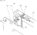
- the coupling mechanism 500 includes a hook-shaped bracket 510 held to hook the outer casing 10, a main bracket-mounted portion 530 defined in the front cover 100, and an auxiliary bracket-mounted portion 550 defined in the rear cover 300.
- the hook-shaped bracket 510 is held to hook the outer casing 10.
- the bracket-mounted portions into which the hook-shaped bracket 510 are mounted are also a key component of the present mechanism.
- the main bracket-mounted portion 530 and the auxiliary bracket-mounted portion 550 together with the hook-shaped bracket 510 constitutes the coupling mechanism 500.
- the hooking portion 512 is formed by bending a metal material having a predetermined width into a hook shape. A distal end of the hooking portion 512 is spaced apart from the bracket body 514 by a predetermined distance. Accordingly, when the hooking portion 512 passes through the accommodation hole 12 of the outer casing 10, the hooking portion 512 is deformed against a portion defining the accommodation hole 12 and is then inserted into the accommodation hole 12. After the hooking portion 512 has passed through the accommodation hole 12 of the outer casing 10, the hooking portion 512 is restored via an elasticity and caught on the rear face of the outer casing 10. This will be described later. For this purpose, the hooking portion 512 is oriented so that a small height side of the inclined portion is directed in the insertion direction of the hook-shaped bracket 510 into the outer casing.
- the bracket body 514 has the same width as the hooking portion 512.
- the bracket body 514 extends in a direction away from the small height side of the hooking portion 512.
- Both first stoppers 514a extend vertically from both longitudinal-directional sides of the bracket body 514 respectively.
- the first stoppers 514s may stop a vertical movement of the main bracket-mounted portion 530 to be described later.
- Each first stopper 514a is bent at a right angle toward the second stopper 516 by a width corresponding to a thickness of the main bracket-mounted portion 530 and then extends in a direction parallel to the bracket body 514. That is, the first stopper 514a is bent from the bracket body 514 at a right angle in an opposite direction to the hooking portion 512 and then is bent at a right angle to extend in a direction parallel to the bracket body 514.
- the first stopper 514a should not affect the insertion and resilient deformation of the hooking portion 512.
- the first stopper 514a is disposed in a region other than a region where the hooking portion 512 is formed.
- the two second stoppers 516 extends from the bracket body 514, and are bent at a right angle downwardly and then bent at a right angle such that the two second stoppers 516 are parallel to the bracket body 514.
- the second stopper 516 should not affect the insertion and resilient deformation of the hooking portion 512. Accordingly, a pair of the second stoppers 516 may be formed into a U-shape by cutting and removing a middle portion of the plate by a width of the hooking portion 512. A distal end of each of the second stoppers 516 may be bent in the direction opposite to the hooking portion 512 to form each third stopper 516a.
- the front cover 100 has the main bracket-mounted portion 530 defined therein corresponding to the shape of the hooking portion 512 of the hook-shaped bracket 510 and the shape of the first stopper 514a.
- the auxiliary bracket-mounted portion 550 corresponding to the shape of the third stopper 516a may be defined in the rear cover 300.
- the front cover 100 is cut at plural locations in the second frame 130 to form plural grooves so that plural hook-shaped brackets 510 are inserted in the grooves respectively.
- the cut portion may define the main bracket-mounted portion 530.
- Each main bracket-mounted portion 530 defines a substantially "90 degree-rotated U" shaped receiving space.
- the hook-shaped bracket 510 is inserted into the receiving space.
- the main bracket-mounted portion 530 includes an bracket-mounted groove 532 cut into the outer casing 10 and a first rib 534 and a second rib 536 defined integrally with the second frame 130 and defining a receiving space.
- the main bracket-mounted portion 530 includes a bracket-mounted groove 532 opening toward the outer casing 10, first ribs 534 and second ribs 536, both ribs being integral with the second frame 130.
- Each first rib 534 is spaced form each second rib 536.
- the bracket-mounted groove 532 may receive the hooking portion 512 which is exposed outwardly.
- the bracket-mounted groove 532 is cut away by a width corresponding to the width of the hooking portion 512.
- the first rib 534 is projected from the inner face of the second frame 130.
- the first ribs 534 may correspond to the two first stopper 514a respectively.
- the bracket body 514 may be disposed between the two first ribs 534.
- the above-mentioned first stopper 514a is vertically bent from the bracket body 514 by a vertical dimension of the first rib 534.
- Each first stopper 514a closely contacts each first rib 534.
- a horizontal portion of the first stopper 514a is in close contact with a bottom face of the first rib 534 as shown in FIG. 7 .
- the first stopper 514a prevents the vertical movement of the hook-shaped bracket 510 on FIG. 7 .
- Each first rib may be formed in an elongate bar.
- the second rib 536 is projected from the inner face of the second frame 130.
- the second ribs 536 may correspond to the two second stopper 516 respectively. Both each first rib and each second rib are disposed between each second rib and each first rib. Each second rib may be formed in an elongate bar.
- Each second stopper 516 closely contacts each second rib 536. A horizontal portion of the second stopper 516 is in close contact with a top face of the second rib 536 as shown in FIG. 7 .
- the second stopper 516 prevents the vertical movement of the hook-shaped bracket 510 on FIG. 7 .
- Each third stopper 516a is inserted between each second rib 536 and a portion defining the auxiliary bracket-mounted portion 550.
- the first rib 534 and the second rib 536 are formed in a bar shape, and the accommodation space in which the first and second stoppers of the hook-shaped bracket 510 are inserted is defined between the first rib 534 and the second rib 536.
- the present disclosure is not limited thereto.
- the main bracket-mounted portion may be constructed into a partially opened box shape such that a portion into which the hook-shaped bracket 510 is inserted and a portion through which the hooking portion 512 is exposed are opened and a remaining portion is blocked.
- the auxiliary bracket-mounted portion 550 is formed on the rear cover 300 from an inner face portion thereof coupled with the front cover 100.
- the auxiliary bracket-mounted portion 550 is defined at a position corresponding to the position of the hook-shaped bracket 510.
- the auxiliary bracket-mounted portion 550 protrudes from the inner face of the rear cover 300 toward the front cover 100.
- the auxiliary bracket-mounted portion 550 is in close contact with the third stopper 516a formed from the distal end of the second stopper 516 of the hook-shaped bracket 510 to press the third stopper 516a. Accordingly, the auxiliary bracket-mounted portion 550 prevents the hook-shaped bracket 510 from moving in the forward and backward directions on FIG. 5 .
- the auxiliary bracket-mounted portion 550 protrudes from the rear cover 300 such that one side of the auxiliary bracket-mounted portion 550 is in close contact with the third stopper 516a when the coupling between the front cover 100 and the rear cover 300 occurs.
- the auxiliary bracket-mounted portion 550 may have a shape such as a U-shape corresponding to the shape of the third stoppers 516a so as to sufficiently cover the third stoppers 516a and thus to closely contact the third stoppers 516a.
- the auxiliary bracket-mounted portion 550 may have a plate shape having a width equal to or greater than an outer width of the pair of third stoppers.
- the hook-shaped bracket 510 is prevented from moving upward and downward with reference to FIG. 5 by the main bracket-mounted portion 530.
- the hook-shaped bracket 510 is prevented from moving back and forth by the auxiliary bracket-mounted portion 550.
- the front cover 100 and the rear cover 300 are mutually coupled to each other. Therefore, a state in which the hook-shaped bracket 510 is stably mounted on the front cover 100 may be maintained.
- the hook-shaped bracket 510 may not be released from the electronic device 30.
- the electronic device 30 may be stably mounted on the outer casing 10.
- the coupling mechanism for coupling the electronic device As described above, manufacturing the coupling mechanism for coupling the electronic device with the rigid material, the durability of the mechanism is improved, and the product cost is reduced. Further, this may prevent breakage of the coupling mechanism when coupling the device to the outer casing. Further, since the coupling mechanism may be simply inserted and installed, the installation convenience and workability are improved.
- FIG. 8 is a side view showing a state before the electronic device is mounted on the outer casing using the coupling mechanism for coupling the electronic device according to an embodiment of the present disclosure.
- FIG. 9 is a side view showing a state where the electronic device has been mounted on the outer casing using the coupling mechanism for coupling the electronic device according to an embodiment of the present disclosure.
- the hook-shaped bracket 510 is coupled to the front cover 100
- the rear cover 300 is coupled to the front cover 100 for subsequent installation of the electronic device 30.
- the electronic device 30 is roughly coupled to the outer casing 10 via the process as described referring to FIG. 5 to FIG. 7 .
- the electronic device 30 is inserted into the accommodation hole 12 in the outer casing 10. At this time, the electronic device 30 is inserted into the outer casing 10 in a direction from a front of the casing 10 to a rear thereof.
- the hooking portion 512 of the hook-shaped bracket 510 is upwardly inclined in a direction toward the front cover 100. Therefore, the hooking portion 512 has a small height portion which is first inserted into the accommodation hole 12. The inclined portion is pressed while the rear cover 300 of the electronic device 30 passes through the accommodation hole 12.
- the hooking portion 512 is pressed and is elastically deformed and thus a distal end of the hooking portion 512 approaches the bracket body 514 and passes through the accommodation hole 12.
- the hooking portion 512 is restored after passing through the accommodation hole 12.
- the hooking portion 512 is located out of the accommodation hole 12 on FIG. 9 , so that the hooking portion 512 is held to hook the outer casing 10.
- the electronic device 30 is in a state in which the front cover 100 and the rear cover 300 thereof face each other with the outer casing 10 being disposed therebetween.
- the hook-shaped bracket 510 may thus allow an engagement between the electronic device 30 and the outer casing 10 to be maintained.
- the electronic device 30 is not detached from the outer casing 10 while the electronic device 30 is fully secured to the outer casing 10 using additional coupling means.
- the coupling state in which the electronic device 30 is roughly pre-coupled to the outer casing 10 before the electronic device 30 is completely fixed to the outer casing using additional coupling means may be referred to as “pre-coupling state” or “roughly coupling state”. While the electronic device 30 is roughly pre-coupled to the outer casing 10, the electronic device 30 is fully secured to the outer casing 10 using additional coupling means.
- the coupling state in which the electronic device 30 is fixedly coupled to the outer casing 10 may be referred to as "post-coupling state” or "completely coupling state”. In this process, the electronic device 30 can be installed to the outer casing only by a single operator.
- FIG. 10 is a perspective view showing a coupling mechanism for coupling an electronic device according to another embodiment of the present disclosure.
- FIG. 11 is a perspective view showing a coupling mechanism for coupling an electronic device according to still another embodiment of the present disclosure.
- a coupling mechanism 500' for coupling an electronic device is the same as the hook-shaped bracket 510 as described in the embodiment of FIG. 6 except that a second stopper 516' is free of a cut portion and is formed of a complete plate.
- the hooking portion 512' may be elastically deformed because the hooking portion 512' and the second stopper 516' are spaced by a predetermined distance. Further, an area of the coupling mechanism as pressed by the auxiliary bracket-mounted portion (Refer to FIG. 5 ) increases. Thus, the installation stability of the hook-shaped bracket 510' is further improved.
- the second stoppers may be formed in the same manner as the second stoppers as described in FIG. 5 such that lengths of the second stoppers increase.
- the rear cover may have holes into which the second stoppers are inserted. In this case, since the second stoppers are inserted and fixed in the rear cover, this has the effect of restricting the forward-backward movement of the hook-shaped bracket like the embodiment of FIG. 5 in which the third stoppers are formed.
- a hook-shaped bracket 510" according to another embodiment of the present disclosure has the same structure as the embodiment described in FIG. 5 , except that each of first stoppers 514a" has a 90-degree rotated U shaped cross section.
- first stoppers 514a" since the first stopper 514a" wraps the first rib (See FIG. 7 ) of the main bracket-mounted portion 530", the upward and downward movement of the hook-shaped bracket 510" may be restricted as in the embodiment of FIG. 5 . Therefore, the installation stability of the coupling mechanism is further improved.
- auxiliary bracket-mounted portion is described as being provided on the rear cover in the above embodiments, the present disclosure is not limited thereto.
- the auxiliary bracket-mounted portion may be formed as a separate component and may be coupled with the hook-shaped bracket.
- the auxiliary bracket-mounted portion is not limited to a specific shape as long as it can prevent the forward-backward movement of the hook-shaped bracket by securing the second stopper or the third stopper of the hook-shaped bracket.
Landscapes
- Engineering & Computer Science (AREA)
- Theoretical Computer Science (AREA)
- General Engineering & Computer Science (AREA)
- Computer Hardware Design (AREA)
- Human Computer Interaction (AREA)
- Physics & Mathematics (AREA)
- General Physics & Mathematics (AREA)
- Microelectronics & Electronic Packaging (AREA)
- Power Engineering (AREA)
- Computer Security & Cryptography (AREA)
- Casings For Electric Apparatus (AREA)
Abstract
Description
- The present disclosure relates to a coupling mechanism capable of pre-coupling an electronic device to an outer casing so that the outer casing and the electronic device are not separated from each other before the electronic device is completely mounted on the outer casing.
- In general, a HMI (Human Machine Interface) device or panel PC means a multifunctional control device in a form of a panel excluding integrated mechanical elements such as a hard disk, a CD driver, a cooling fan, etc. such that the device may be easily used by a field worker.
- The HMI device is provided in various forms including a fixed panel form in which the device may be fixed to a panel and a removable panel form in which the operator removes the device from the panel.
-
FIG. 1 shows a conventional coupling structure for an electronic device.FIG. 2 shows another conventional coupling structure for an electronic device. - As shown in
FIG. 1 , when installing anelectronic device 5 such as an HMI device or panel PC, an operator first inserts theelectronic device 5 into amounting hole 2 defined in anouter casing 1. Thereafter, a hook-shaped bracket 7 formed on theelectronic device 5 is hooked into theouter casing 1. Thus, theelectronic device 5 may be prevented from being separated from theouter casing 1. In this connection, thebracket 7 is made of plastic. The hook-shaped portion passes through a hole defined in a front cover or rear cover of theelectronic device 5 and is inserted into thehole 2 and caught into theouter casing 1. Further, the front or rear cover is detachable. An unexposed portion of thebracket 7 may be typically composed of 3 to 5 coupling parts such as springs, pins, and the like. - Alternatively, as shown in
FIG. 2 , for assembling an electronic device 5', a bracket 7' having a plurality of hooks is mounted between afront cover 5a or arear cover 5b. Then, thefront cover 5a and therear cover 5b are coupled with each other via separate fastening bolts. The electronic device 5' is then installed onto theouter casing 1. In this case, a construction and material of the bracket 7' are the same as inFIG. 1 . - However, since the conventional bracket for the electronic device is made of a plastic material, there is a risk that the hook-shaped portion of the bracket is bent or broken when the bracket is inserted into the mounting hole in the outer casing. Since the hook-shaped bracket is composed of the 3 to 5 parts, the assembling process is complicated and the cost of the bracket is increased.
- Further, for an electronic device without a hook-shaped bracket, while one operator must keep a state in which the electronic device is inserted into the outer casing, another operator must work to fix the electronic device onto a back of the outer casing. Therefore, it is difficult to install the electronic device by one operator. Further, the assembling time is extended.
- In order to solve the problem, a purpose of the present disclosure is to provide a coupling mechanism for coupling an electronic device to an outer casing by which one operator can easily mount the electronic device into the outer casing.
- Another purpose of the present disclosure is to provide a coupling mechanism for coupling an electronic device to an outer casing in which a structure of a bracket is improved to reduce a cost and to simplify an assembly process and to reduce an assembly time.
- In one aspect of the present disclosure, there is provided a coupling mechanism for coupling an electronic device to an outer casing, wherein the outer casing has an accommodation hole defined therein sized to correspond to a size of the electronic device, wherein the electronic device includes a front cover exposed out of the outer casing, and a rear cover coupled to a rear of the front cover the coupling mechanism comprising: a plurality of hook-shaped brackets interposed between the front and rear covers and wherein the plurality of hook-shaped brackets pass through the accommodation hole and are held to hook the outer casing while the front cover and the rear cover are coupled to each other; a plurality of main bracket-mounted portion defined in the front cover wherein each hook-shaped bracket is mounted into each main bracket-mounted portion; and a plurality of auxiliary bracket-mounted portion disposed on the rear cover wherein each auxiliary bracket-mounted portion is engaged with each hook-shaped bracket when the front cover and the rear cover are coupled to each other.
- In one implementation, each hook-shaped bracket includes: a hooking portion held to hook the outer casing; a bracket body having the same width as the hooking portion and extending horizontally from one end of the hooking portion; first stoppers a integrally formed with the bracket body at both opposing sides thereof; and a second stopper vertically extending and then horizontally extending from one end of the bracket body and such that the second stopper faces away the bracket body.
- In one implementation, the hook-shaped bracket is made of rigid metal, wherein when the electronic device is inserted into the accommodation hole, the hooking portion and the bracket body are pressed and elastically deformed, wherein after the electronic device has been inserted into the accommodation hole, the hooking portion and the bracket body are elastically restored such that the hooking portion is held to hook the outer casing.
- In one implementation, each main bracket-mounted portion includes: a bracket-mounted groove defined in a second frame, wherein the second frame is coupled to a first frame along an edge thereof, wherein the first frame is coupled to a front face of the front cover wherein the groove is open toward the outer casing; both first ribs and both second ribs integrally formed with the second frame, wherein a receiving space for receiving the hook-shaped bracket is defined between the both first ribs and both second ribs.
- In one implementation, the bracket-mounted groove has a width corresponding to a width of the hooking portion, wherein each of the first ribs includes an elongate bar, wherein the bar protrudes from an inner face of the second frame, wherein the bracket body are disposed between the bars of the first ribs, wherein each of the second ribs includes an elongate bar, wherein the bar protrudes from the inner face of the second frame, wherein each first stopper a and each second stopper are disposed between each first rib and each second rib, wherein each second rib is disposed below each first rib.
- In one implementation, the first stopper a vertically downwardly extends and then horizontally outwardly extends from the bracket body, wherein the first stopper a has a horizontal dimension equal to a horizontal dimension of the first rib, wherein the first stopper a is in close contact with the first rib, wherein the second stopper is in close contact with the second rib.
- In one implementation, the hook-shaped bracket includes a third stopper extending vertically downwardly from a distal end of the second stopper, wherein the auxiliary bracket-mounted portion protrudes in a plate form from an inner face of the rear cover and at a position corresponding to a position of the main bracket-mounted portion, wherein the auxiliary bracket-mounted portion contacts and presses against the third stopper when the front cover and the rear cover are coupled to each other.
- In one implementation, the second stopper has a horizontal portion branching into a U shape, wherein each third stopper is formed at a distal end of each of prongs of the U shape.
- In one implementation, the second stopper has a horizontal portion having a width greater than a width of the bracket body, wherein the third stopper is formed at a distal end of the second stopper.
- In one implementation, each first stopper has a 90-degree rotated U shaped cross section such that the first stopper wraps the first rib.
- According to the present disclosure, manufacturing the coupling mechanism for coupling the electronic device with a rigid material may allow the mechanism production cost to be reduced, and allow installation convenience of the device and durability of the mechanism to be improved. Further, improving the structure of the coupling mechanism may allow the electronic device to be installed by only one operator and may shorten the assembly time.
- Further specific effects of the present disclosure as well as the effects as described above will be described in conduction with illustrations of specific details for carrying out the invention.
-
-
FIG. 1 shows a conventional coupling structure for an electronic device. -
FIG. 2 shows another conventional coupling structure for an electronic device. -
FIG. 3 is a front view showing an electronic device mounted on an outer casing. -
FIG. 4 is a back view showing the electronic device mounted on the outer casing. -
FIG. 5 is an exploded perspective view of a coupling mechanism for coupling an electronic device, according to one embodiment of the present disclosure. -
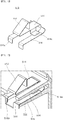
FIG. 6 is an enlarged perspective view of major components ofFIG. 5 . -
FIG. 7 is a partial perspective view of a state in which a coupling mechanism for coupling an electronic device inFIG. 5 is mounted. -
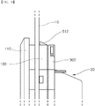
FIG. 8 is a side view showing a state before the electronic device is mounted on the outer casing using the coupling mechanism for coupling the electronic device according to an embodiment of the present disclosure. -
FIG. 9 is a side view showing a state where the electronic device has been mounted on the outer casing using the coupling mechanism for coupling the electronic device according to an embodiment of the present disclosure. -
FIG. 10 is a perspective view showing a coupling mechanism for coupling an electronic device according to another embodiment of the present disclosure. -
FIG. 11 is a perspective view showing a coupling mechanism for coupling an electronic device according to still another embodiment of the present disclosure. - Hereinafter, a coupling mechanism for coupling an electronic device in accordance with the present disclosure will be described with refence to the accompanying drawings.
- For simplicity and clarity of illustration, elements in the figures. are not necessarily drawn to scale. The same reference numbers in different figures. denote the same or similar elements, and as such perform similar functionality. Also, descriptions and details of well-known steps and elements are omitted for simplicity of the description. Furthermore, in the following detailed description of the present disclosure, numerous specific details are set forth in order to provide a thorough understanding of the present disclosure. However, it will be understood that the present disclosure may be practiced without these specific details. In other instances, well-known methods, procedures, components, and circuits have not been described in detail so as not to unnecessarily obscure aspects of the present disclosure.
- The above objects, features and advantages will become apparent from the detailed description with reference to the accompanying drawings. Embodiments are described in sufficient detail to enable those skilled in the art in the art to easily practice the technical idea of the present disclosure. Detailed descriptions of well-known functions or configurations may be omitted in order not to unnecessarily obscure the gist of the present disclosure. Hereinafter, embodiments of the present disclosure will be described in detail with reference to the accompanying drawings. Throughout the drawings, like reference numerals refer to like elements.
- Unless defined otherwise, all terms used herein have the same meaning as commonly understood by one of ordinary skill in the art. When the terms used herein are in conflict with a general meaning of the term, the meaning of the term is in accordance with a definition used herein.
- Examples of various embodiments are illustrated and described further below. It will be understood that the description herein is not intended to limit the claims to the specific embodiments described. On the contrary, it is intended to cover alternatives, modifications, and equivalents as may be included within the spirit and scope of the present disclosure as defined by the appended claims.
- The terminology used herein is for the purpose of describing particular embodiments only and is not intended to be limiting of the present disclosure. As used herein, the singular forms "a" and "an" are intended to include the plural forms as well, unless the context clearly indicates otherwise. It will be further understood that the terms "comprises", "comprising", "includes", and "including" when used in this specification, specify the presence of the stated features, integers, operations, elements, and/or components, but do not preclude the presence or addition of one or more other features, integers, operations, elements, components, and/or portions thereof. As used herein, the term "and/or" includes any and all combinations of one or more of the associated listed items. Expression such as "at least one of' when preceding a list of elements may modify the entire list of elements and may not modify the individual elements of the list.
- It will be understood that, although the terms "first", "second", "third", and so on may be used herein to describe various elements, components, regions, layers and/or sections, these elements, components, regions, layers and/or sections should not be limited by these terms. These terms are used to distinguish one element, component, region, layer or section from another element, component, region, layer or section. Thus, a first element, component, region, layer or section described below could be termed a second element, component, region, layer or section, without departing from the spirit and scope of the present disclosure.
- In addition, it will also be understood that when a first element or layer is referred to as being present "on" a second element or layer, the first element may be disposed directly on the second element or may be disposed indirectly on the second element with a third element or layer being disposed between the first and second elements or layers. It will be understood that when an element or layer is referred to as being "connected to", or "coupled to" another element or layer, it can be directly on, connected to, or coupled to the other element or layer, or one or more intervening elements or layers may be present. In addition, it will also be understood that when an element or layer is referred to as being "between" two elements or layers, it can be the only element or layer between the two elements or layers, or one or more intervening elements or layers may also be present.
-
FIG. 3 is a front view showing an electronic device mounted on an outer casing.FIG. 4 is a back view showing the electronic device mounted on the outer casing. The figures show only a portion of the outer casing. - As shown in
FIG. 3 andFIG. 4 , anelectronic device 30 includes an HMI device or a panel PC, and has a panel shape having a predetermined thickness. Theelectronic device 30 may be installed into an separateouter casing 10. Theouter casing 10 has anaccommodation hole 12 defined therein having a size corresponding to a size of theelectronic device 30. - The
electronic device 30 has a front portion exposed to an outside from a front of theouter casing 10 and a rear portion corresponding to a rear of theouter casing 10. Theelectronic device 30 may include afront cover 100 that covers a portion of the front portion and arear cover 300 that covers partially or entirely the rear portion. - The
front cover 100 covers and supports an edge of the front portion of theelectronic device 30. The front portion may be composed of, for example, a display on which an image is displayed. Thefront cover 100 has a shape that surrounds an edge of the display. A portion of the front cover exposed out of theouter casing 10 may be defined as a front portion of the front cover. A face of thefront cover 100 facing forwardly may be defined as a front face thereof. A portion of the front cover facing rearwardly may be defined as a rear portion of the front cover. A face of thefront cover 100 facing rearwardly may be defined as a rear face thereof. In this connection,FIG. 3 shows a front face of theouter casing 10 andFIG. 4 shows a rear face of theouter casing 10. - The
front cover 100 may include afirst frame 110 covering the front portion of theelectronic device 30 and asecond frame 130 covering a top, bottom, left and right edges of thedevice 30. Acoupling device 500 for coupling theelectronic device 30 to theouter casing 10 is disposed on thesecond frame 130 of thefront cover 100. - The
rear cover 300 is detachably coupled to the rear portion of thefront cover 100. Therear cover 300 covers various components of theelectronic device 30 to prevent exposure thereof to the outside. Therear cover 300 is coupled with thefront cover 100 to prevent thecoupling device 500, which will be described later, from moving. -
FIG. 5 is an exploded perspective view of a coupling mechanism for coupling an electronic device, according to one embodiment of the present disclosure.FIG. 6 is an enlarged perspective view of major components ofFIG. 5 .FIG. 7 is a partial perspective view of a state in which a coupling mechanism for coupling an electronic device inFIG. 5 is mounted. - As shown in
FIGS. 5 to 7 , thecoupling mechanism 500 is inserted between thefront cover 100 and therear cover 300. Thecoupling mechanism 500 is held in theaccommodation hole 12 of theouter casing 10 while thefront cover 100 and therear cover 300 are coupled to each other. Thus, thecoupling mechanism 500 allows theelectronic device 30 to remain in a coupled state to theouter casing 10. To this end, thecoupling mechanism 500 includes a hook-shapedbracket 510 held to hook theouter casing 10, a main bracket-mountedportion 530 defined in thefront cover 100, and an auxiliary bracket-mountedportion 550 defined in therear cover 300. The hook-shapedbracket 510 is held to hook theouter casing 10. The bracket-mounted portions into which the hook-shapedbracket 510 are mounted are also a key component of the present mechanism. Thus, in the present disclosure, the main bracket-mountedportion 530 and the auxiliary bracket-mountedportion 550 together with the hook-shapedbracket 510 constitutes thecoupling mechanism 500. - As shown in
FIG. 6 , the hook-shapedbracket 510 is made of a rigid metal material. The hook-shapedbracket 510 is produced by bending a plate-shaped metal material a plurality of times. Thus, the hook-shapedbracket 510 has a predetermined elasticity. The hook-shapedbracket 510 may include a hookingportion 512 held to hook theouter casing 10, abracket body 514 extending to one end of the hookingportion 512,first stoppers 514a extending from both side of thebracket body 514, andsecond stoppers 516 that extends and bends from one end of thebracket body 514. A distal end portion of thesecond stopper 516 is bent to form athird stopper 516a. - The hooking
portion 512 is formed by bending a metal material having a predetermined width into a hook shape. A distal end of the hookingportion 512 is spaced apart from thebracket body 514 by a predetermined distance. Accordingly, when the hookingportion 512 passes through theaccommodation hole 12 of theouter casing 10, the hookingportion 512 is deformed against a portion defining theaccommodation hole 12 and is then inserted into theaccommodation hole 12. After the hookingportion 512 has passed through theaccommodation hole 12 of theouter casing 10, the hookingportion 512 is restored via an elasticity and caught on the rear face of theouter casing 10. This will be described later. For this purpose, the hookingportion 512 is oriented so that a small height side of the inclined portion is directed in the insertion direction of the hook-shapedbracket 510 into the outer casing. - The
bracket body 514 has the same width as the hookingportion 512. Thebracket body 514 extends in a direction away from the small height side of the hookingportion 512. Bothfirst stoppers 514a extend vertically from both longitudinal-directional sides of thebracket body 514 respectively. The first stoppers 514s may stop a vertical movement of the main bracket-mountedportion 530 to be described later. - Each
first stopper 514a is bent at a right angle toward thesecond stopper 516 by a width corresponding to a thickness of the main bracket-mountedportion 530 and then extends in a direction parallel to thebracket body 514. That is, thefirst stopper 514a is bent from thebracket body 514 at a right angle in an opposite direction to the hookingportion 512 and then is bent at a right angle to extend in a direction parallel to thebracket body 514. Thefirst stopper 514a should not affect the insertion and resilient deformation of the hookingportion 512. Thus, thefirst stopper 514a is disposed in a region other than a region where the hookingportion 512 is formed. - The two
second stoppers 516 extends from thebracket body 514, and are bent at a right angle downwardly and then bent at a right angle such that the twosecond stoppers 516 are parallel to thebracket body 514. Thesecond stopper 516 should not affect the insertion and resilient deformation of the hookingportion 512. Accordingly, a pair of thesecond stoppers 516 may be formed into a U-shape by cutting and removing a middle portion of the plate by a width of the hookingportion 512. A distal end of each of thesecond stoppers 516 may be bent in the direction opposite to the hookingportion 512 to form eachthird stopper 516a. - The
front cover 100 has the main bracket-mountedportion 530 defined therein corresponding to the shape of the hookingportion 512 of the hook-shapedbracket 510 and the shape of thefirst stopper 514a. The auxiliary bracket-mountedportion 550 corresponding to the shape of thethird stopper 516a may be defined in therear cover 300. - As shown in
FIGS. 5 and7 , thefront cover 100 is cut at plural locations in thesecond frame 130 to form plural grooves so that plural hook-shapedbrackets 510 are inserted in the grooves respectively. The cut portion may define the main bracket-mountedportion 530. - Each main bracket-mounted
portion 530 defines a substantially "90 degree-rotated U" shaped receiving space. The hook-shapedbracket 510 is inserted into the receiving space. The main bracket-mountedportion 530 includes an bracket-mountedgroove 532 cut into theouter casing 10 and afirst rib 534 and asecond rib 536 defined integrally with thesecond frame 130 and defining a receiving space. The main bracket-mountedportion 530 includes a bracket-mountedgroove 532 opening toward theouter casing 10,first ribs 534 andsecond ribs 536, both ribs being integral with thesecond frame 130. Eachfirst rib 534 is spaced form eachsecond rib 536. - The bracket-mounted
groove 532 may receive the hookingportion 512 which is exposed outwardly. The bracket-mountedgroove 532 is cut away by a width corresponding to the width of the hookingportion 512. - The
first rib 534 is projected from the inner face of thesecond frame 130. Thefirst ribs 534 may correspond to the twofirst stopper 514a respectively. Thebracket body 514 may be disposed between the twofirst ribs 534. The above-mentionedfirst stopper 514a is vertically bent from thebracket body 514 by a vertical dimension of thefirst rib 534. Eachfirst stopper 514a closely contacts eachfirst rib 534. A horizontal portion of thefirst stopper 514a is in close contact with a bottom face of thefirst rib 534 as shown inFIG. 7 . Thefirst stopper 514a prevents the vertical movement of the hook-shapedbracket 510 onFIG. 7 . Each first rib may be formed in an elongate bar. - The
second rib 536 is projected from the inner face of thesecond frame 130. Thesecond ribs 536 may correspond to the twosecond stopper 516 respectively. Both each first rib and each second rib are disposed between each second rib and each first rib. Each second rib may be formed in an elongate bar. Eachsecond stopper 516 closely contacts eachsecond rib 536. A horizontal portion of thesecond stopper 516 is in close contact with a top face of thesecond rib 536 as shown inFIG. 7 . Thesecond stopper 516 prevents the vertical movement of the hook-shapedbracket 510 onFIG. 7 . Eachthird stopper 516a is inserted between eachsecond rib 536 and a portion defining the auxiliary bracket-mountedportion 550. - In the above-described embodiment, the
first rib 534 and thesecond rib 536 are formed in a bar shape, and the accommodation space in which the first and second stoppers of the hook-shapedbracket 510 are inserted is defined between thefirst rib 534 and thesecond rib 536. The present disclosure is not limited thereto. The main bracket-mounted portion may be constructed into a partially opened box shape such that a portion into which the hook-shapedbracket 510 is inserted and a portion through which the hookingportion 512 is exposed are opened and a remaining portion is blocked. - Referring to
FIG. 5 andFIG. 7 , the auxiliary bracket-mountedportion 550 is formed on therear cover 300 from an inner face portion thereof coupled with thefront cover 100. The auxiliary bracket-mountedportion 550 is defined at a position corresponding to the position of the hook-shapedbracket 510. The auxiliary bracket-mountedportion 550 protrudes from the inner face of therear cover 300 toward thefront cover 100. The auxiliary bracket-mountedportion 550 is in close contact with thethird stopper 516a formed from the distal end of thesecond stopper 516 of the hook-shapedbracket 510 to press thethird stopper 516a. Accordingly, the auxiliary bracket-mountedportion 550 prevents the hook-shapedbracket 510 from moving in the forward and backward directions onFIG. 5 . Accordingly, the auxiliary bracket-mountedportion 550 protrudes from therear cover 300 such that one side of the auxiliary bracket-mountedportion 550 is in close contact with thethird stopper 516a when the coupling between thefront cover 100 and therear cover 300 occurs. Further, the auxiliary bracket-mountedportion 550 may have a shape such as a U-shape corresponding to the shape of thethird stoppers 516a so as to sufficiently cover thethird stoppers 516a and thus to closely contact thethird stoppers 516a. Alternatively, the auxiliary bracket-mountedportion 550 may have a plate shape having a width equal to or greater than an outer width of the pair of third stoppers. - As described above, the hook-shaped
bracket 510 is prevented from moving upward and downward with reference toFIG. 5 by the main bracket-mountedportion 530. The hook-shapedbracket 510 is prevented from moving back and forth by the auxiliary bracket-mountedportion 550. After mounting the hook-shapedbracket 510 into the main bracket-mountedportion 530, thefront cover 100 and therear cover 300 are mutually coupled to each other. Therefore, a state in which the hook-shapedbracket 510 is stably mounted on thefront cover 100 may be maintained. Thus, the hook-shapedbracket 510 may not be released from theelectronic device 30. Thus, theelectronic device 30 may be stably mounted on theouter casing 10. - As described above, manufacturing the coupling mechanism for coupling the electronic device with the rigid material, the durability of the mechanism is improved, and the product cost is reduced. Further, this may prevent breakage of the coupling mechanism when coupling the device to the outer casing. Further, since the coupling mechanism may be simply inserted and installed, the installation convenience and workability are improved.
- A process of installing the electronic device to the outer casing using the coupling mechanism for coupling the electronic device according to the embodiment of the present disclosure having the above-described configuration will be described as follows.
-
FIG. 8 is a side view showing a state before the electronic device is mounted on the outer casing using the coupling mechanism for coupling the electronic device according to an embodiment of the present disclosure.FIG. 9 is a side view showing a state where the electronic device has been mounted on the outer casing using the coupling mechanism for coupling the electronic device according to an embodiment of the present disclosure. - While the hook-shaped
bracket 510 is coupled to thefront cover 100, therear cover 300 is coupled to thefront cover 100 for subsequent installation of theelectronic device 30. Then, theelectronic device 30 is roughly coupled to theouter casing 10 via the process as described referring toFIG. 5 to FIG. 7 . - As shown in
FIG. 8 , theelectronic device 30 is inserted into theaccommodation hole 12 in theouter casing 10. At this time, theelectronic device 30 is inserted into theouter casing 10 in a direction from a front of thecasing 10 to a rear thereof. - The hooking
portion 512 of the hook-shapedbracket 510 is upwardly inclined in a direction toward thefront cover 100. Therefore, the hookingportion 512 has a small height portion which is first inserted into theaccommodation hole 12. The inclined portion is pressed while therear cover 300 of theelectronic device 30 passes through theaccommodation hole 12. - The hooking
portion 512 is pressed and is elastically deformed and thus a distal end of the hookingportion 512 approaches thebracket body 514 and passes through theaccommodation hole 12. The hookingportion 512 is restored after passing through theaccommodation hole 12. When the hookingportion 512 is restored, the hookingportion 512 is located out of theaccommodation hole 12 onFIG. 9 , so that the hookingportion 512 is held to hook theouter casing 10. Thus, theelectronic device 30 is in a state in which thefront cover 100 and therear cover 300 thereof face each other with theouter casing 10 being disposed therebetween. The hook-shapedbracket 510 may thus allow an engagement between theelectronic device 30 and theouter casing 10 to be maintained. Thus, theelectronic device 30 is not detached from theouter casing 10 while theelectronic device 30 is fully secured to theouter casing 10 using additional coupling means. - In this connection, the coupling state in which the
electronic device 30 is roughly pre-coupled to theouter casing 10 before theelectronic device 30 is completely fixed to the outer casing using additional coupling means may be referred to as "pre-coupling state" or "roughly coupling state". While theelectronic device 30 is roughly pre-coupled to theouter casing 10, theelectronic device 30 is fully secured to theouter casing 10 using additional coupling means. The coupling state in which theelectronic device 30 is fixedly coupled to theouter casing 10 may be referred to as "post-coupling state" or "completely coupling state". In this process, theelectronic device 30 can be installed to the outer casing only by a single operator. - Hereinafter, a coupling mechanism for coupling an electronic device according to another embodiment of the present disclosure will be described.
-
FIG. 10 is a perspective view showing a coupling mechanism for coupling an electronic device according to another embodiment of the present disclosure.FIG. 11 is a perspective view showing a coupling mechanism for coupling an electronic device according to still another embodiment of the present disclosure. - As shown in
FIG. 10 , a coupling mechanism 500' for coupling an electronic device according to another embodiment of the present disclosure is the same as the hook-shapedbracket 510 as described in the embodiment ofFIG. 6 except that a second stopper 516' is free of a cut portion and is formed of a complete plate. When the hook-shaped bracket 510' has this construction, the hooking portion 512' may be elastically deformed because the hooking portion 512' and the second stopper 516' are spaced by a predetermined distance. Further, an area of the coupling mechanism as pressed by the auxiliary bracket-mounted portion (Refer toFIG. 5 ) increases. Thus, the installation stability of the hook-shaped bracket 510' is further improved. - Although not shown in the drawing, instead of forming the third stoppers by bending the distal end of the second stoppers, the second stoppers may be formed in the same manner as the second stoppers as described in
FIG. 5 such that lengths of the second stoppers increase. Further, instead of the auxiliary bracket-mounted portion, the rear cover may have holes into which the second stoppers are inserted. In this case, since the second stoppers are inserted and fixed in the rear cover, this has the effect of restricting the forward-backward movement of the hook-shaped bracket like the embodiment ofFIG. 5 in which the third stoppers are formed. - Alternatively, as shown in
FIG. 11 , a hook-shapedbracket 510" according to another embodiment of the present disclosure has the same structure as the embodiment described inFIG. 5 , except that each offirst stoppers 514a" has a 90-degree rotated U shaped cross section. In this case, since thefirst stopper 514a" wraps the first rib (SeeFIG. 7 ) of the main bracket-mountedportion 530", the upward and downward movement of the hook-shapedbracket 510" may be restricted as in the embodiment ofFIG. 5 . Therefore, the installation stability of the coupling mechanism is further improved. - Although the auxiliary bracket-mounted portion is described as being provided on the rear cover in the above embodiments, the present disclosure is not limited thereto. The auxiliary bracket-mounted portion may be formed as a separate component and may be coupled with the hook-shaped bracket. The auxiliary bracket-mounted portion is not limited to a specific shape as long as it can prevent the forward-backward movement of the hook-shaped bracket by securing the second stopper or the third stopper of the hook-shaped bracket.
- It will be apparent to those skilled in the art that various modifications and variations may be made in the present invention without departing from the spirit of the present disclosure. The technical scope of the present disclosure is not limited to the contents described in the embodiments but should be determined by the claims and equivalents thereof.
Claims (10)
- A coupling mechanism 500, 500' or 500" for coupling an electronic device 30 to an outer casing 10, wherein the outer casing has an accommodation hole 12 defined therein sized to correspond to a size of the electronic device, wherein the electronic device 30 includes a front cover 100 exposed out of the outer casing 10, and a rear cover 300 coupled to a rear of the front cover 100, the coupling mechanism 500 comprising:a plurality of hook-shaped brackets 510 interposed between the front and rear covers 100 and 300, wherein the plurality of hook-shaped brackets 510 pass through the accommodation hole 12 and are held to hook the outer casing while the front cover 100 and the rear cover 300 are coupled to each other;a plurality of main bracket-mounted portion 530 defined in the front cover 100, wherein each hook-shaped bracket 510 is mounted into each main bracket-mounted portion 530; anda plurality of auxiliary bracket-mounted portion 550 disposed on the rear cover 300, wherein each auxiliary bracket-mounted portion 550 is engaged with each hook-shaped bracket 510 when the front cover 100 and the rear cover 300 are coupled to each other.
- The coupling mechanism of claim 1, wherein each hook-shaped bracket 510 includes:a hooking portion 512 held to hook the outer casing 10;a bracket body 514 having the same width as the hooking portion 512 and extending horizontally from one end of the hooking portion 512;first stoppers 514a integrally formed with the bracket body 514 at both opposing sides thereof; anda second stopper 516 vertically extending and then horizontally extending from one end of the bracket body 514 and such that the second stopper 516 faces away the bracket body 514.
- The coupling mechanism of claim 2, wherein the hook-shaped bracket 510 is made of rigid metal,
wherein when the electronic device 30 is inserted into the accommodation hole 12, the hooking portion 512 and the bracket body 514 are pressed and elastically deformed,
wherein after the electronic device 30 has been inserted into the accommodation hole 12, the hooking portion 512 and the bracket body 514 are elastically restored such that the hooking portion 512 is held to hook the outer casing 10. - The coupling mechanism of claim 2 or 3, wherein each main bracket-mounted portion 530 includes:a bracket-mounted groove 532 defined in a second frame 130, wherein the second frame 130 is coupled to a first frame 110 along an edge thereof, wherein the first frame is coupled to a front face of the front cover 100, wherein the groove 532 is open toward the outer casing;both first ribs 534 and both second ribs 536 integrally formed with the second frame 130, wherein a receiving space for receiving the hook-shaped bracket 510 is defined between the both first ribs 534 and both second ribs 536.
- The coupling mechanism of claim 4, wherein the bracket-mounted groove 532 has a width corresponding to a width of the hooking portion 512,
wherein each of the first ribs 534 includes an elongate bar, wherein the bar protrudes from an inner face of the second frame 130, wherein the bracket body 514 are disposed between the bars of the first ribs 534,
wherein each of the second ribs 536 includes an elongate bar, wherein the bar protrudes from the inner face of the second frame 130, wherein each first stopper 514a and each second stopper 516 are disposed between each first rib and each second rib, wherein each second rib is disposed below each first rib. - The coupling mechanism of claim 5, wherein the first stopper 514a vertically downwardly extends and then horizontally outwardly extends from the bracket body 514, wherein the first stopper 514a has a horizontal dimension equal to a horizontal dimension of the first rib 534, wherein the first stopper 514a is in close contact with the first rib 534,
wherein the second stopper 516 is in close contact with the second rib 536. - The coupling mechanism of claim 6, wherein the hook-shaped bracket 510 includes a third stopper 516 extending vertically downwardly from a distal end of the second stopper 516,
wherein the auxiliary bracket-mounted portion 550 protrudes in a plate form from an inner face of the rear cover 300 and at a position corresponding to a position of the main bracket-mounted portion 530,
wherein the auxiliary bracket-mounted portion 550 contacts and presses against the third stopper 516a when the front cover 100 and the rear cover 300 are coupled to each other. - The coupling mechanism of claim 7, wherein the second stopper has a horizontal portion branching into a U shape, wherein each third stopper 516a is formed at a distal end of each of prongs of the U shape.
- The coupling mechanism of claim 7, wherein the second stopper 516' has a horizontal portion having a width greater than a width of the bracket body 514', wherein the third stopper 516a' is formed at a distal end of the second stopper 516'.
- The coupling mechanism of claim 6, wherein each first stopper 514" has a 90-degree rotated U shaped cross section such that the first stopper 514a" wraps the first rib 534".
Applications Claiming Priority (1)
| Application Number | Priority Date | Filing Date | Title |
|---|---|---|---|
| KR1020180020405A KR101976432B1 (en) | 2018-02-21 | 2018-02-21 | Coupling device of electronic device |
Publications (2)
| Publication Number | Publication Date |
|---|---|
| EP3531233A1 true EP3531233A1 (en) | 2019-08-28 |
| EP3531233B1 EP3531233B1 (en) | 2020-10-28 |
Family
ID=65598416
Family Applications (1)
| Application Number | Title | Priority Date | Filing Date |
|---|---|---|---|
| EP19158107.3A Active EP3531233B1 (en) | 2018-02-21 | 2019-02-19 | Coupling mechanism for coupling electronic device |
Country Status (6)
| Country | Link |
|---|---|
| US (1) | US10667415B2 (en) |
| EP (1) | EP3531233B1 (en) |
| JP (1) | JP6724181B2 (en) |
| KR (1) | KR101976432B1 (en) |
| CN (1) | CN110174926B (en) |
| ES (1) | ES2836704T3 (en) |
Families Citing this family (6)
| Publication number | Priority date | Publication date | Assignee | Title |
|---|---|---|---|---|
| KR102431932B1 (en) * | 2020-06-11 | 2022-08-11 | 이덕환 | MCC with Panel Unit |
| JP7581898B2 (en) * | 2021-01-18 | 2024-11-13 | オムロン株式会社 | Electrical Equipment |
| KR102426354B1 (en) | 2021-07-19 | 2022-07-29 | 엘지전자 주식회사 | Mask apparatus |
| KR102661736B1 (en) * | 2022-08-19 | 2024-04-26 | 엘에스일렉트릭(주) | Fitting member and power electronic apparatus include the same |
| KR102661767B1 (en) * | 2022-12-02 | 2024-04-30 | 주식회사 오성전자 | Remote control for electronic products having double locking structure |
| KR102924931B1 (en) * | 2023-12-28 | 2026-02-09 | 주식회사 오성전자 | remote control having a battery cover with a two-stage open structure |
Citations (2)
| Publication number | Priority date | Publication date | Assignee | Title |
|---|---|---|---|---|
| US4754533A (en) * | 1986-02-18 | 1988-07-05 | Siemens Aktiengesellschaft | Retaining clip for fastening a flap component part to a housing part |
| DE102016102138A1 (en) * | 2016-02-08 | 2017-08-10 | Phoenix Contact Gmbh & Co. Kg | Mounting frame for attaching a functional unit to a device wall |
Family Cites Families (14)
| Publication number | Priority date | Publication date | Assignee | Title |
|---|---|---|---|---|
| JP2646185B2 (en) * | 1993-09-10 | 1997-08-25 | スタンレー電気株式会社 | Box body |
| JPH11268595A (en) * | 1998-03-25 | 1999-10-05 | Sony Corp | Acoustic equipment for vehicles |
| JP4254999B2 (en) * | 2002-12-26 | 2009-04-15 | パナソニック株式会社 | Housing wall-hanging structure |
| CN2613803Y (en) * | 2003-02-17 | 2004-04-28 | 鸿富锦精密工业(深圳)有限公司 | Fixing structure for extension card |
| US6826863B1 (en) * | 2003-09-09 | 2004-12-07 | Pacific Digital Corporation | Combination video monitor and detachable picture frame |
| KR20080019472A (en) * | 2006-08-28 | 2008-03-04 | 주식회사 대우일렉트로닉스 | Wall-mounted devices |
| CN201039613Y (en) * | 2007-04-28 | 2008-03-19 | 佛山市顺德区顺达电脑厂有限公司 | Fixing and connection structure for panel and shell of electronic device |
| CN102194589A (en) * | 2010-03-03 | 2011-09-21 | 英业达股份有限公司 | Two-piece power button snap-in structure |
| AU2013203842A1 (en) * | 2010-03-29 | 2013-05-02 | Eat Dirt, Llc | Cases and covers for electronic handheld devices |
| JP5502642B2 (en) * | 2010-07-22 | 2014-05-28 | 株式会社デジタル | Temporary fastening structure for electronic equipment |
| JP5649638B2 (en) * | 2012-12-10 | 2015-01-07 | 三菱電機株式会社 | Control device |
| CN104076885B (en) * | 2013-03-27 | 2017-08-08 | 光宝电子(广州)有限公司 | The support holding structure of interface card |
| JP6102411B2 (en) * | 2013-03-28 | 2017-03-29 | オムロン株式会社 | Electrical equipment and fixtures for electrical equipment |
| KR102325744B1 (en) * | 2017-03-06 | 2021-11-11 | 엘에스일렉트릭(주) | Bracket for fixing electronic device and electronic device fixing structure |
-
2018
- 2018-02-21 KR KR1020180020405A patent/KR101976432B1/en active Active
-
2019
- 2019-02-01 JP JP2019017096A patent/JP6724181B2/en active Active
- 2019-02-15 CN CN201910117009.3A patent/CN110174926B/en active Active
- 2019-02-15 US US16/277,359 patent/US10667415B2/en active Active
- 2019-02-19 EP EP19158107.3A patent/EP3531233B1/en active Active
- 2019-02-19 ES ES19158107T patent/ES2836704T3/en active Active
Patent Citations (2)
| Publication number | Priority date | Publication date | Assignee | Title |
|---|---|---|---|---|
| US4754533A (en) * | 1986-02-18 | 1988-07-05 | Siemens Aktiengesellschaft | Retaining clip for fastening a flap component part to a housing part |
| DE102016102138A1 (en) * | 2016-02-08 | 2017-08-10 | Phoenix Contact Gmbh & Co. Kg | Mounting frame for attaching a functional unit to a device wall |
Also Published As
| Publication number | Publication date |
|---|---|
| US20190261522A1 (en) | 2019-08-22 |
| JP2019145788A (en) | 2019-08-29 |
| CN110174926B (en) | 2023-09-19 |
| ES2836704T3 (en) | 2021-06-28 |
| CN110174926A (en) | 2019-08-27 |
| US10667415B2 (en) | 2020-05-26 |
| EP3531233B1 (en) | 2020-10-28 |
| JP6724181B2 (en) | 2020-07-15 |
| KR101976432B1 (en) | 2019-05-09 |
Similar Documents
| Publication | Publication Date | Title |
|---|---|---|
| US10667415B2 (en) | Coupling mechanism for coupling electronic device | |
| US8897018B2 (en) | Display device and television receiver | |
| US7486506B2 (en) | Mounting assembly for enclosure cover | |
| US20090148638A1 (en) | Electronic apparatus | |
| JP5147492B2 (en) | Electrical junction box storage box | |
| US8672425B2 (en) | Cabinet structure assembly | |
| CN103003858B (en) | Display device | |
| EP2497993B1 (en) | Cabinet structure assembly | |
| US20060166549A1 (en) | Wire cover for connectors | |
| US20150151636A1 (en) | Vehicular display apparatus | |
| JP6183653B2 (en) | Mounting structure for instrument panel decorative parts | |
| KR20200018157A (en) | Head up display device for vehicle | |
| EP2059036A1 (en) | Display | |
| US20080252861A1 (en) | Rear projection type display apparatus | |
| JP3740997B2 (en) | Wiring plate | |
| JP7762553B2 (en) | display device | |
| KR102425648B1 (en) | Head up display device for vehicle | |
| JP2006069276A (en) | Rear camera mounting structure | |
| KR101470643B1 (en) | Display device | |
| JP7626010B2 (en) | In-vehicle equipment | |
| JP7333018B2 (en) | Waist seal mounting structure | |
| EP1839951B1 (en) | In-vehicle mount type equipment | |
| JP2010148339A (en) | Plate for wiring device, and wiring device | |
| WO2026034104A1 (en) | Clothing processing device | |
| JP2008037176A (en) | Attachment / detachment structure of vehicle antenna |
Legal Events
| Date | Code | Title | Description |
|---|---|---|---|
| PUAI | Public reference made under article 153(3) epc to a published international application that has entered the european phase |
Free format text: ORIGINAL CODE: 0009012 |
|
| STAA | Information on the status of an ep patent application or granted ep patent |
Free format text: STATUS: THE APPLICATION HAS BEEN PUBLISHED |
|
| AK | Designated contracting states |
Kind code of ref document: A1 Designated state(s): AL AT BE BG CH CY CZ DE DK EE ES FI FR GB GR HR HU IE IS IT LI LT LU LV MC MK MT NL NO PL PT RO RS SE SI SK SM TR |
|
| AX | Request for extension of the european patent |
Extension state: BA ME |
|
| STAA | Information on the status of an ep patent application or granted ep patent |
Free format text: STATUS: REQUEST FOR EXAMINATION WAS MADE |
|
| 17P | Request for examination filed |
Effective date: 20200226 |
|
| RBV | Designated contracting states (corrected) |
Designated state(s): AL AT BE BG CH CY CZ DE DK EE ES FI FR GB GR HR HU IE IS IT LI LT LU LV MC MK MT NL NO PL PT RO RS SE SI SK SM TR |
|
| GRAP | Despatch of communication of intention to grant a patent |
Free format text: ORIGINAL CODE: EPIDOSNIGR1 |
|
| STAA | Information on the status of an ep patent application or granted ep patent |
Free format text: STATUS: GRANT OF PATENT IS INTENDED |
|
| INTG | Intention to grant announced |
Effective date: 20200626 |
|
| GRAS | Grant fee paid |
Free format text: ORIGINAL CODE: EPIDOSNIGR3 |
|
| GRAA | (expected) grant |
Free format text: ORIGINAL CODE: 0009210 |
|
| STAA | Information on the status of an ep patent application or granted ep patent |
Free format text: STATUS: THE PATENT HAS BEEN GRANTED |
|
| AK | Designated contracting states |
Kind code of ref document: B1 Designated state(s): AL AT BE BG CH CY CZ DE DK EE ES FI FR GB GR HR HU IE IS IT LI LT LU LV MC MK MT NL NO PL PT RO RS SE SI SK SM TR |
|
| REG | Reference to a national code |
Ref country code: GB Ref legal event code: FG4D |
|
| REG | Reference to a national code |
Ref country code: CH Ref legal event code: EP |
|
| REG | Reference to a national code |
Ref country code: AT Ref legal event code: REF Ref document number: 1328861 Country of ref document: AT Kind code of ref document: T Effective date: 20201115 |
|
| REG | Reference to a national code |
Ref country code: DE Ref legal event code: R096 Ref document number: 602019001060 Country of ref document: DE |
|
| REG | Reference to a national code |
Ref country code: IE Ref legal event code: FG4D |
|
| REG | Reference to a national code |
Ref country code: AT Ref legal event code: MK05 Ref document number: 1328861 Country of ref document: AT Kind code of ref document: T Effective date: 20201028 |
|
| REG | Reference to a national code |
Ref country code: NL Ref legal event code: MP Effective date: 20201028 |
|
| PG25 | Lapsed in a contracting state [announced via postgrant information from national office to epo] |
Ref country code: GR Free format text: LAPSE BECAUSE OF FAILURE TO SUBMIT A TRANSLATION OF THE DESCRIPTION OR TO PAY THE FEE WITHIN THE PRESCRIBED TIME-LIMIT Effective date: 20210129 Ref country code: NO Free format text: LAPSE BECAUSE OF FAILURE TO SUBMIT A TRANSLATION OF THE DESCRIPTION OR TO PAY THE FEE WITHIN THE PRESCRIBED TIME-LIMIT Effective date: 20210128 Ref country code: FI Free format text: LAPSE BECAUSE OF FAILURE TO SUBMIT A TRANSLATION OF THE DESCRIPTION OR TO PAY THE FEE WITHIN THE PRESCRIBED TIME-LIMIT Effective date: 20201028 Ref country code: PT Free format text: LAPSE BECAUSE OF FAILURE TO SUBMIT A TRANSLATION OF THE DESCRIPTION OR TO PAY THE FEE WITHIN THE PRESCRIBED TIME-LIMIT Effective date: 20210301 Ref country code: RS Free format text: LAPSE BECAUSE OF FAILURE TO SUBMIT A TRANSLATION OF THE DESCRIPTION OR TO PAY THE FEE WITHIN THE PRESCRIBED TIME-LIMIT Effective date: 20201028 |
|
| REG | Reference to a national code |
Ref country code: LT Ref legal event code: MG4D |
|
| PG25 | Lapsed in a contracting state [announced via postgrant information from national office to epo] |
Ref country code: BG Free format text: LAPSE BECAUSE OF FAILURE TO SUBMIT A TRANSLATION OF THE DESCRIPTION OR TO PAY THE FEE WITHIN THE PRESCRIBED TIME-LIMIT Effective date: 20210128 Ref country code: IS Free format text: LAPSE BECAUSE OF FAILURE TO SUBMIT A TRANSLATION OF THE DESCRIPTION OR TO PAY THE FEE WITHIN THE PRESCRIBED TIME-LIMIT Effective date: 20210228 Ref country code: PL Free format text: LAPSE BECAUSE OF FAILURE TO SUBMIT A TRANSLATION OF THE DESCRIPTION OR TO PAY THE FEE WITHIN THE PRESCRIBED TIME-LIMIT Effective date: 20201028 Ref country code: LV Free format text: LAPSE BECAUSE OF FAILURE TO SUBMIT A TRANSLATION OF THE DESCRIPTION OR TO PAY THE FEE WITHIN THE PRESCRIBED TIME-LIMIT Effective date: 20201028 Ref country code: SE Free format text: LAPSE BECAUSE OF FAILURE TO SUBMIT A TRANSLATION OF THE DESCRIPTION OR TO PAY THE FEE WITHIN THE PRESCRIBED TIME-LIMIT Effective date: 20201028 Ref country code: AT Free format text: LAPSE BECAUSE OF FAILURE TO SUBMIT A TRANSLATION OF THE DESCRIPTION OR TO PAY THE FEE WITHIN THE PRESCRIBED TIME-LIMIT Effective date: 20201028 |
|
| REG | Reference to a national code |
Ref country code: ES Ref legal event code: FG2A Ref document number: 2836704 Country of ref document: ES Kind code of ref document: T3 Effective date: 20210628 |
|
| PG25 | Lapsed in a contracting state [announced via postgrant information from national office to epo] |
Ref country code: HR Free format text: LAPSE BECAUSE OF FAILURE TO SUBMIT A TRANSLATION OF THE DESCRIPTION OR TO PAY THE FEE WITHIN THE PRESCRIBED TIME-LIMIT Effective date: 20201028 Ref country code: NL Free format text: LAPSE BECAUSE OF FAILURE TO SUBMIT A TRANSLATION OF THE DESCRIPTION OR TO PAY THE FEE WITHIN THE PRESCRIBED TIME-LIMIT Effective date: 20201028 |
|
| REG | Reference to a national code |
Ref country code: DE Ref legal event code: R097 Ref document number: 602019001060 Country of ref document: DE |
|
| PG25 | Lapsed in a contracting state [announced via postgrant information from national office to epo] |
Ref country code: CZ Free format text: LAPSE BECAUSE OF FAILURE TO SUBMIT A TRANSLATION OF THE DESCRIPTION OR TO PAY THE FEE WITHIN THE PRESCRIBED TIME-LIMIT Effective date: 20201028 Ref country code: EE Free format text: LAPSE BECAUSE OF FAILURE TO SUBMIT A TRANSLATION OF THE DESCRIPTION OR TO PAY THE FEE WITHIN THE PRESCRIBED TIME-LIMIT Effective date: 20201028 Ref country code: SK Free format text: LAPSE BECAUSE OF FAILURE TO SUBMIT A TRANSLATION OF THE DESCRIPTION OR TO PAY THE FEE WITHIN THE PRESCRIBED TIME-LIMIT Effective date: 20201028 Ref country code: SM Free format text: LAPSE BECAUSE OF FAILURE TO SUBMIT A TRANSLATION OF THE DESCRIPTION OR TO PAY THE FEE WITHIN THE PRESCRIBED TIME-LIMIT Effective date: 20201028 Ref country code: RO Free format text: LAPSE BECAUSE OF FAILURE TO SUBMIT A TRANSLATION OF THE DESCRIPTION OR TO PAY THE FEE WITHIN THE PRESCRIBED TIME-LIMIT Effective date: 20201028 Ref country code: LT Free format text: LAPSE BECAUSE OF FAILURE TO SUBMIT A TRANSLATION OF THE DESCRIPTION OR TO PAY THE FEE WITHIN THE PRESCRIBED TIME-LIMIT Effective date: 20201028 |
|
| PG25 | Lapsed in a contracting state [announced via postgrant information from national office to epo] |
Ref country code: DK Free format text: LAPSE BECAUSE OF FAILURE TO SUBMIT A TRANSLATION OF THE DESCRIPTION OR TO PAY THE FEE WITHIN THE PRESCRIBED TIME-LIMIT Effective date: 20201028 |
|
| PLBE | No opposition filed within time limit |
Free format text: ORIGINAL CODE: 0009261 |
|
| STAA | Information on the status of an ep patent application or granted ep patent |
Free format text: STATUS: NO OPPOSITION FILED WITHIN TIME LIMIT |
|
| PG25 | Lapsed in a contracting state [announced via postgrant information from national office to epo] |
Ref country code: MC Free format text: LAPSE BECAUSE OF FAILURE TO SUBMIT A TRANSLATION OF THE DESCRIPTION OR TO PAY THE FEE WITHIN THE PRESCRIBED TIME-LIMIT Effective date: 20201028 |
|
| 26N | No opposition filed |
Effective date: 20210729 |
|
| REG | Reference to a national code |
Ref country code: BE Ref legal event code: MM Effective date: 20210228 |
|
| PG25 | Lapsed in a contracting state [announced via postgrant information from national office to epo] |
Ref country code: AL Free format text: LAPSE BECAUSE OF FAILURE TO SUBMIT A TRANSLATION OF THE DESCRIPTION OR TO PAY THE FEE WITHIN THE PRESCRIBED TIME-LIMIT Effective date: 20201028 Ref country code: LU Free format text: LAPSE BECAUSE OF NON-PAYMENT OF DUE FEES Effective date: 20210219 |
|
| PG25 | Lapsed in a contracting state [announced via postgrant information from national office to epo] |
Ref country code: SI Free format text: LAPSE BECAUSE OF FAILURE TO SUBMIT A TRANSLATION OF THE DESCRIPTION OR TO PAY THE FEE WITHIN THE PRESCRIBED TIME-LIMIT Effective date: 20201028 |
|
| PG25 | Lapsed in a contracting state [announced via postgrant information from national office to epo] |
Ref country code: IE Free format text: LAPSE BECAUSE OF NON-PAYMENT OF DUE FEES Effective date: 20210219 |
|
| PG25 | Lapsed in a contracting state [announced via postgrant information from national office to epo] |
Ref country code: IS Free format text: LAPSE BECAUSE OF FAILURE TO SUBMIT A TRANSLATION OF THE DESCRIPTION OR TO PAY THE FEE WITHIN THE PRESCRIBED TIME-LIMIT Effective date: 20210228 |
|
| PG25 | Lapsed in a contracting state [announced via postgrant information from national office to epo] |
Ref country code: BE Free format text: LAPSE BECAUSE OF NON-PAYMENT OF DUE FEES Effective date: 20210228 |
|
| REG | Reference to a national code |
Ref country code: CH Ref legal event code: PL |
|
| PG25 | Lapsed in a contracting state [announced via postgrant information from national office to epo] |
Ref country code: LI Free format text: LAPSE BECAUSE OF NON-PAYMENT OF DUE FEES Effective date: 20220228 Ref country code: CH Free format text: LAPSE BECAUSE OF NON-PAYMENT OF DUE FEES Effective date: 20220228 |
|
| PG25 | Lapsed in a contracting state [announced via postgrant information from national office to epo] |
Ref country code: CY Free format text: LAPSE BECAUSE OF FAILURE TO SUBMIT A TRANSLATION OF THE DESCRIPTION OR TO PAY THE FEE WITHIN THE PRESCRIBED TIME-LIMIT Effective date: 20201028 |
|
| PG25 | Lapsed in a contracting state [announced via postgrant information from national office to epo] |
Ref country code: HU Free format text: LAPSE BECAUSE OF FAILURE TO SUBMIT A TRANSLATION OF THE DESCRIPTION OR TO PAY THE FEE WITHIN THE PRESCRIBED TIME-LIMIT; INVALID AB INITIO Effective date: 20190219 |
|
| P01 | Opt-out of the competence of the unified patent court (upc) registered |
Effective date: 20230625 |
|
| PG25 | Lapsed in a contracting state [announced via postgrant information from national office to epo] |
Ref country code: MK Free format text: LAPSE BECAUSE OF FAILURE TO SUBMIT A TRANSLATION OF THE DESCRIPTION OR TO PAY THE FEE WITHIN THE PRESCRIBED TIME-LIMIT Effective date: 20201028 |
|
| PG25 | Lapsed in a contracting state [announced via postgrant information from national office to epo] |
Ref country code: MT Free format text: LAPSE BECAUSE OF FAILURE TO SUBMIT A TRANSLATION OF THE DESCRIPTION OR TO PAY THE FEE WITHIN THE PRESCRIBED TIME-LIMIT Effective date: 20201028 |
|
| PG25 | Lapsed in a contracting state [announced via postgrant information from national office to epo] |
Ref country code: TR Free format text: LAPSE BECAUSE OF FAILURE TO SUBMIT A TRANSLATION OF THE DESCRIPTION OR TO PAY THE FEE WITHIN THE PRESCRIBED TIME-LIMIT Effective date: 20201028 |
|
| PGFP | Annual fee paid to national office [announced via postgrant information from national office to epo] |
Ref country code: GB Payment date: 20251208 Year of fee payment: 8 |
|
| PGFP | Annual fee paid to national office [announced via postgrant information from national office to epo] |
Ref country code: FR Payment date: 20251209 Year of fee payment: 8 |
|
| PGFP | Annual fee paid to national office [announced via postgrant information from national office to epo] |
Ref country code: ES Payment date: 20260324 Year of fee payment: 8 |
|
| PGFP | Annual fee paid to national office [announced via postgrant information from national office to epo] |
Ref country code: DE Payment date: 20251208 Year of fee payment: 8 |
|
| PGFP | Annual fee paid to national office [announced via postgrant information from national office to epo] |
Ref country code: IT Payment date: 20251209 Year of fee payment: 8 |