EP3531111A1 - Image gray scale recognition-based raman spectrum detection apparatus and method - Google Patents
Image gray scale recognition-based raman spectrum detection apparatus and method Download PDFInfo
- Publication number
- EP3531111A1 EP3531111A1 EP18826176.2A EP18826176A EP3531111A1 EP 3531111 A1 EP3531111 A1 EP 3531111A1 EP 18826176 A EP18826176 A EP 18826176A EP 3531111 A1 EP3531111 A1 EP 3531111A1
- Authority
- EP
- European Patent Office
- Prior art keywords
- detection
- image
- detection apparatus
- raman
- raman spectrum
- Prior art date
- Legal status (The legal status is an assumption and is not a legal conclusion. Google has not performed a legal analysis and makes no representation as to the accuracy of the status listed.)
- Pending
Links
Images

Classifications
-
- G—PHYSICS
- G01—MEASURING; TESTING
- G01J—MEASUREMENT OF INTENSITY, VELOCITY, SPECTRAL CONTENT, POLARISATION, PHASE OR PULSE CHARACTERISTICS OF INFRARED, VISIBLE OR ULTRAVIOLET LIGHT; COLORIMETRY; RADIATION PYROMETRY
- G01J3/00—Spectrometry; Spectrophotometry; Monochromators; Measuring colours
- G01J3/28—Investigating the spectrum
- G01J3/2823—Imaging spectrometer
-
- G—PHYSICS
- G01—MEASURING; TESTING
- G01J—MEASUREMENT OF INTENSITY, VELOCITY, SPECTRAL CONTENT, POLARISATION, PHASE OR PULSE CHARACTERISTICS OF INFRARED, VISIBLE OR ULTRAVIOLET LIGHT; COLORIMETRY; RADIATION PYROMETRY
- G01J3/00—Spectrometry; Spectrophotometry; Monochromators; Measuring colours
- G01J3/02—Details
- G01J3/0205—Optical elements not provided otherwise, e.g. optical manifolds, diffusers, windows
- G01J3/0227—Optical elements not provided otherwise, e.g. optical manifolds, diffusers, windows using notch filters
-
- G—PHYSICS
- G01—MEASURING; TESTING
- G01J—MEASUREMENT OF INTENSITY, VELOCITY, SPECTRAL CONTENT, POLARISATION, PHASE OR PULSE CHARACTERISTICS OF INFRARED, VISIBLE OR ULTRAVIOLET LIGHT; COLORIMETRY; RADIATION PYROMETRY
- G01J3/00—Spectrometry; Spectrophotometry; Monochromators; Measuring colours
- G01J3/02—Details
- G01J3/0205—Optical elements not provided otherwise, e.g. optical manifolds, diffusers, windows
- G01J3/0248—Optical elements not provided otherwise, e.g. optical manifolds, diffusers, windows using a sighting port, e.g. camera or human eye
-
- G—PHYSICS
- G01—MEASURING; TESTING
- G01J—MEASUREMENT OF INTENSITY, VELOCITY, SPECTRAL CONTENT, POLARISATION, PHASE OR PULSE CHARACTERISTICS OF INFRARED, VISIBLE OR ULTRAVIOLET LIGHT; COLORIMETRY; RADIATION PYROMETRY
- G01J3/00—Spectrometry; Spectrophotometry; Monochromators; Measuring colours
- G01J3/02—Details
- G01J3/0262—Constructional arrangements for removing stray light
-
- G—PHYSICS
- G01—MEASURING; TESTING
- G01J—MEASUREMENT OF INTENSITY, VELOCITY, SPECTRAL CONTENT, POLARISATION, PHASE OR PULSE CHARACTERISTICS OF INFRARED, VISIBLE OR ULTRAVIOLET LIGHT; COLORIMETRY; RADIATION PYROMETRY
- G01J3/00—Spectrometry; Spectrophotometry; Monochromators; Measuring colours
- G01J3/02—Details
- G01J3/027—Control of working procedures of a spectrometer; Failure detection; Bandwidth calculation
-
- G—PHYSICS
- G01—MEASURING; TESTING
- G01J—MEASUREMENT OF INTENSITY, VELOCITY, SPECTRAL CONTENT, POLARISATION, PHASE OR PULSE CHARACTERISTICS OF INFRARED, VISIBLE OR ULTRAVIOLET LIGHT; COLORIMETRY; RADIATION PYROMETRY
- G01J3/00—Spectrometry; Spectrophotometry; Monochromators; Measuring colours
- G01J3/28—Investigating the spectrum
- G01J3/44—Raman spectrometry; Scattering spectrometry ; Fluorescence spectrometry
-
- G—PHYSICS
- G01—MEASURING; TESTING
- G01J—MEASUREMENT OF INTENSITY, VELOCITY, SPECTRAL CONTENT, POLARISATION, PHASE OR PULSE CHARACTERISTICS OF INFRARED, VISIBLE OR ULTRAVIOLET LIGHT; COLORIMETRY; RADIATION PYROMETRY
- G01J3/00—Spectrometry; Spectrophotometry; Monochromators; Measuring colours
- G01J3/28—Investigating the spectrum
- G01J3/44—Raman spectrometry; Scattering spectrometry ; Fluorescence spectrometry
- G01J3/4412—Scattering spectrometry
-
- G—PHYSICS
- G01—MEASURING; TESTING
- G01J—MEASUREMENT OF INTENSITY, VELOCITY, SPECTRAL CONTENT, POLARISATION, PHASE OR PULSE CHARACTERISTICS OF INFRARED, VISIBLE OR ULTRAVIOLET LIGHT; COLORIMETRY; RADIATION PYROMETRY
- G01J5/00—Radiation pyrometry, e.g. infrared or optical thermometry
- G01J5/02—Constructional details
- G01J5/025—Interfacing a pyrometer to an external device or network; User interface
-
- G—PHYSICS
- G01—MEASURING; TESTING
- G01N—INVESTIGATING OR ANALYSING MATERIALS BY DETERMINING THEIR CHEMICAL OR PHYSICAL PROPERTIES
- G01N21/00—Investigating or analysing materials by the use of optical means, i.e. using sub-millimetre waves, infrared, visible or ultraviolet light
- G01N21/17—Systems in which incident light is modified in accordance with the properties of the material investigated
- G01N21/25—Colour; Spectral properties, i.e. comparison of effect of material on the light at two or more different wavelengths or wavelength bands
- G01N21/27—Colour; Spectral properties, i.e. comparison of effect of material on the light at two or more different wavelengths or wavelength bands using photo-electric detection ; circuits for computing concentration
-
- G—PHYSICS
- G01—MEASURING; TESTING
- G01N—INVESTIGATING OR ANALYSING MATERIALS BY DETERMINING THEIR CHEMICAL OR PHYSICAL PROPERTIES
- G01N21/00—Investigating or analysing materials by the use of optical means, i.e. using sub-millimetre waves, infrared, visible or ultraviolet light
- G01N21/62—Systems in which the material investigated is excited whereby it emits light or causes a change in wavelength of the incident light
- G01N21/63—Systems in which the material investigated is excited whereby it emits light or causes a change in wavelength of the incident light optically excited
- G01N21/65—Raman scattering
-
- G—PHYSICS
- G01—MEASURING; TESTING
- G01J—MEASUREMENT OF INTENSITY, VELOCITY, SPECTRAL CONTENT, POLARISATION, PHASE OR PULSE CHARACTERISTICS OF INFRARED, VISIBLE OR ULTRAVIOLET LIGHT; COLORIMETRY; RADIATION PYROMETRY
- G01J5/00—Radiation pyrometry, e.g. infrared or optical thermometry
- G01J5/0066—Radiation pyrometry, e.g. infrared or optical thermometry for hot spots detection
-
- G—PHYSICS
- G01—MEASURING; TESTING
- G01J—MEASUREMENT OF INTENSITY, VELOCITY, SPECTRAL CONTENT, POLARISATION, PHASE OR PULSE CHARACTERISTICS OF INFRARED, VISIBLE OR ULTRAVIOLET LIGHT; COLORIMETRY; RADIATION PYROMETRY
- G01J5/00—Radiation pyrometry, e.g. infrared or optical thermometry
- G01J5/48—Thermography; Techniques using wholly visual means
-
- G—PHYSICS
- G01—MEASURING; TESTING
- G01J—MEASUREMENT OF INTENSITY, VELOCITY, SPECTRAL CONTENT, POLARISATION, PHASE OR PULSE CHARACTERISTICS OF INFRARED, VISIBLE OR ULTRAVIOLET LIGHT; COLORIMETRY; RADIATION PYROMETRY
- G01J5/00—Radiation pyrometry, e.g. infrared or optical thermometry
- G01J5/48—Thermography; Techniques using wholly visual means
- G01J5/485—Temperature profile
-
- H—ELECTRICITY
- H04—ELECTRIC COMMUNICATION TECHNIQUE
- H04N—PICTORIAL COMMUNICATION, e.g. TELEVISION
- H04N23/00—Cameras or camera modules comprising electronic image sensors; Control thereof
- H04N23/10—Cameras or camera modules comprising electronic image sensors; Control thereof for generating image signals from different wavelengths
- H04N23/11—Cameras or camera modules comprising electronic image sensors; Control thereof for generating image signals from different wavelengths for generating image signals from visible and infrared light wavelengths
Definitions
- Embodiments of the present disclosure generally relate to a detection apparatus and a detection method, and particularly, to Raman spectrum detection apparatus and method based on image grayscale recognition.
- Raman spectrum analysis technology is a non-contact spectrum analysis technology based on Raman scattering effect, which can qualitatively and quantitatively analyze the composition of a substance.
- Raman spectrum is a molecular vibration spectrum that can reflect the fingerprint characteristics of molecules, and can be used for the inspection of substance.
- Raman spectrometer can inspect and identify the substance by the Raman spectrum generated from the Raman scattering effect of the object to be inspected with respect to exciting light.
- Raman spectrum analysis technology has been widely used in the fields of dangerous goods inspection and substance identification.
- substance identification because the colors and shapes of various substances are different from each other, it is usually hard for a person to accurately determine the properties of the substance.
- Raman spectrum is determined by the molecular energy level structure of the object to be inspected, thus the Raman spectrum can be used as the "fingerprint" information of a substance for substance identification. Therefore, Raman spectrum analysis technology has been widely used in the fields of customs, public safety, food & medicine, environment, etc.
- Laser having a high power density is generally used as an exciting light source in Raman spectrum detection, for example, near infrared laser light of 785nm has a stronger thermal effect, thus in case that components of the object to be detected are not known, an indiscreet detection made by using such laser light may possibly cause the object to be detected to be burned and damaged by the laser light. If the object to be detected is a flammable and explosive chemical, such indiscreet detection may lead to burning, exploding and the like, resulting in personal and property loss.
- An object of the present disclosure is to at least partly solve or alleviate at least one aspect of the above-mentioned and other disadvantages or problems in prior arts.
- a Raman spectrum detection apparatus based on image grayscale recognition.
- the detection apparatus may comprise: a laser configured to emit laser light to an object to be detected; an imaging device configured to obtain an image of the object; a Raman spectrometer configured to receive Raman light coming from the object and generated under irradiation of the laser light so as to obtain a Raman spectrum of the object; and a controller configured to control a detection operation of the detection apparatus based on grayscales of the image.
- the controller may be further configured to: determine, based on the image, a grayscale value of each of pixels of the image; compare the grayscale value of each of the pixels with a preset grayscale threshold; and control the detection operation of the detection apparatus based on a comparison result.
- the controller is further configured to: determine a percentage of the number of the pixels, grayscale values of which are smaller than the grayscale threshold, with respect to a total pixel number of the image; and compare the determined percentage with a preset percentage threshold, and control the detection operation of the detection apparatus based on a comparison result.
- the controller may be further configured to: determine, based on the image, a grayscale value of each of pixels of the image; calculate an average grayscale value of all pixels of the image based on the grayscale values of the pixels; and compare the average grayscale value with a preset average grayscale threshold, and control the detection operation of the detection apparatus based on a comparison result.
- the detection apparatus may further comprise: a first beam splitter disposed in a Raman light path from the object to the Raman spectrometer, and configured to guide the laser light emitted from the laser to the object and to transmit therethrough the Raman light from the object to the Raman spectrometer.
- the first beam splitter may include a long-wavelength pass dichroic mirror.
- a second beam splitter disposed in a Raman light path from the object to the Raman spectrometer, and configured to reflect visible light from the object to the imaging device such that the object is imaged by the imaging device and to allow the laser light emitted from the laser and the Raman light from the object to pass therethrough.
- the second beam splitter may include a long-wavelength pass dichroic mirror.
- the detection apparatus may further comprise at least one of following optical members: a first optical filter disposed in the Raman light path at a position downstream of the first beam splitter and the second beam splitter, and configured to filter out Rayleigh light of a light signal; a second optical filter disposed between the laser and the first beam splitter and configured to limit a wavelength of the laser light emitted by the laser within a desired wavelength band; and a third optical filter disposed between the imaging device and the second beam splitter and configured to filter out laser light from the object.
- a first optical filter disposed in the Raman light path at a position downstream of the first beam splitter and the second beam splitter, and configured to filter out Rayleigh light of a light signal
- a second optical filter disposed between the laser and the first beam splitter and configured to limit a wavelength of the laser light emitted by the laser within a desired wavelength band
- a third optical filter disposed between the imaging device and the second beam splitter and configured to filter out laser light from the object.
- the detection apparatus may further comprise at least one of following optical members: a first convergent lens or lens set disposed between the second beam splitter and the object; a second convergent lens or lens set disposed between the imaging device and the second beam splitter; and a third convergent lens or lens set disposed between the Raman spectrometer and the first beam splitter.
- each of the first to third convergent lenses or lens sets described herein may include a single convex lens as shown in the drawings, or may include a lens set composed of a plurality of lens and having a light converging function.
- the detection apparatus may further comprise a light source configured to illuminate the object.
- a method of detecting a Raman spectrum of an object based on image grayscale recognition there is provided a method of detecting a Raman spectrum of an object based on image grayscale recognition.
- the method may comprise: obtaining an image of an object to be detected; determining a grayscale value of each of pixels of the image; determining, based on grayscale values of the pixels of the image, whether or not the object is adaptive to a Raman spectrum detection to be implemented by irradiating the object by laser light; implementing the Raman spectrum detection if it is determined the object is adaptive to the Raman spectrum detection; and if it is determined the object is not adaptive to the Raman spectrum detection, terminating the Raman spectrum detection, or adjusting a detection parameter for the Raman spectrum detection such that the object is adaptive to the Raman spectrum detection with the adjusted detection parameter.
- the step of determining, based on grayscale values of the pixels of the image, whether or not the object is adaptive to a Raman spectrum detection to be implemented by irradiating the object by laser light may comprise: comparing the grayscale value of each of the pixels with a preset grayscale threshold so as to determine a deep-colored pixel percentage of the image, which is a percentage of the number of the pixels with grayscale values smaller than the grayscale threshold, with respect to a total pixel number of the image; and comparing the deep-colored pixel percentage with a preset percentage threshold, and concluding that the object is not adaptive to the Raman spectrum detection if the deep-colored pixel percentage is larger than the threshold percentage, and that the object is adaptive to the Raman spectrum detection if the deep-colored pixel percentage is smaller than or equal to the threshold percentage.
- the step of determining, based on grayscale values of the pixels of the image, whether or not the object is adaptive to a Raman spectrum detection to be implemented by irradiating the object by laser light may comprise: calculating an average grayscale value of all pixels of the image; and comparing the average grayscale value with a preset average grayscale threshold, and concluding that the object is not adaptive to the Raman spectrum detection if the average grayscale value is smaller than the average grayscale value, and that the object is adaptive to the Raman spectrum detection if the average grayscale value is greater than or equal to the average grayscale value.
- the method may further comprise: sending an alarm signal if it is determined that the object is not adaptive to the Raman spectrum detection.
- adjusting a detection parameter for the Raman spectrum detection includes: reducing light emitting power of the laser for generating the laser light; and/or shortening a time period of the laser for continuously emitting the laser light.
- a detection apparatus comprising: a laser configured to emit laser light to an object to be detected; a Raman spectrometer configured to receive Raman light from the object; an imaging device configured to obtain an image of the object; and a controller configured to control an operation of the detection apparatus based on grayscales of the image.
- FIG. 1 is a schematic diagram of a detection apparatus according to an embodiment of the present disclosure.
- a detection apparatus 100 comprises: a laser 110 configured to emit laser light 111 towards an object 120 to be detected; a Raman spectrometer 130 configured to receive a Raman light signal 112 generated from the object 120 under the irradiation of the laser light; an imaging device 140 configured to obtain or capture an image of the object 120; and a controller 150 configured to control an operation of the detection apparatus 100 based on grayscales of the image
- laser light emitted by a laser In order to excite Raman scattering effect from an object to be detected, laser light emitted by a laser generally has a higher power density, which will generate a stronger thermal effect; if the color of the object to be detected is deeper (for example, dark gray, black or the like), the object will absorb more laser light and thereby increase rapidly in its surface temperature, which may cause the object to be partially ablated, or even exploded if the object is gunpower. If an inspector is inadequately trained or careless, the above phenomena may occur, or even the field inspector may be damaged.
- technique schemes of the present disclosure provide an imaging device for obtaining an image of the object to be detected, such as an optical image, determine whether or not the object to be detected is deep colored or black, and determine a subsequent detection operation based on the determined color shade of the object.
- the imaging device 140 may include a CCD imaging device, a CMOS imaging device or other known imaging devices or a light sensor.
- the image of the object may be an image of the whole of the object obtained in a certain direction, or an image of a detected portion of the object, which depends on the dimensions of the object 120 to be detected, parameters of the detection apparatus 100 such as a detection area, For example, if the object to be detected is a gemstone having a very small size, the imaging device may obtain an image of the whole of one side face of the object; if the object to be detected has a larger size, the imaging device may image partially a portion to be detected of the object.
- "color of an object” may be a color of the whole of a detected face of the object, or may be a color of a partial part of the detected portion of the object.
- a color shade of an object may be determined according to grayscales of an image of the object.
- the controller 150 is configured to: determine, based on the image obtained by the imaging device 140, a grayscale value of each of pixels of the image, compare the grayscale value of each of the pixels with a preset grayscale threshold, and control the detection operation of the detection apparatus based on a comparison result.
- the controller 150 may determine a percentage of the number of the pixels, grayscale values of which are smaller than the grayscale threshold, relative to a total pixel number of the image, compare the determined percentage with a preset percentage threshold, and control the detection operation of the detection apparatus 100 based on a comparison result.
- a grayscale processing operation may be made by using an image processor on the image of the object obtained by the imaging device, so as to obtain the grayscale value (a value from 0 to 255) of each of pixels of the image.
- the image processor may be integrated into the imaging device 140 (that is, the imaging device 140 comprises the image processor); in another example, the image processor may also be integrated into the controller 150 (that is, the controller 150 comprises the image processor); in other examples, the image processor may also be provided in a field operated computer or in a remote control center.
- grayscale processing of the images of the object to be detected may be implemented by software or algorithms stored in a storage device of a field operated computer, of a computer in a remote control center or of the controller 150 so as to obtain grayscale values of respective pixels of the image.
- the grayscale threshold may be set based on actual conditions or requirements.
- the grayscale threshold may be set as 30, more or less.
- the controller 150 may compare the grayscale value of each of the pixels in the image of object with the preset grayscale threshold, so as to determine a percentage (hereinafter referred to as "deep-colored pixel percentage") of the number of the pixels, grayscale values of which are smaller than the grayscale threshold, relative to a total pixel number of the image. It will be understood that if the grayscale values of all or most of the pixels are smaller than the grayscale threshold, it shows that the color of the object appearing on the image is deeper.
- the threshold percentage may be set according to actual requirements (For example, the threshold percentage is set as 85%, 90% or 95%), and the deep-colored pixel percentage determined in above step may be compared with the threshold percentage, so that the detection apparatus 100 is controlled based on the comparison result.
- the controller 150 determines that the grayscale values of 85% or more of the pixels in the image are smaller than the grayscale threshold (that is, the deep-colored pixel percentage is greater than or equal to 85%), the controller 150 can conclude that the object to be detected has a deeper color and is not adaptive to a detection operation, and then instruct the laser 110 to not emit laser light, to reduce a light emitting power of the laser, to shorten a time period of the laser for continuously emitting the laser light, or to terminate the detection operation.
- the detection apparatus 100 may further comprise an alarm device 160, and the controller 150 may be further configured to control an operation of the alarm device 160 based on the comparison result between the deep-colored pixel percentage and the threshold percentage. For example, if the controller 150 determines that the deep-colored pixel percentage is greater than the threshold percentage, it may instruct the alarm device 160 to send an alarm signal so as to warn a related operator that the current object to be detected is not adaptive to be detected due to its deeper color and/or that the current detection operation has been terminated.
- the alarm signal may include at least of a special acoustical signal and an image signal.
- the controller 150 may conclude that the color shade of the current object to be detected is adaptive to a detection operation. In such a case, the controller 150 may instruct the laser 110 to emit laser light, for implementing subsequent detection operation.
- the controller 150 may also be configured to: determine, based on the image, a grayscale value of each of pixels of the image; calculate an average grayscale value of all pixels of the image based on the grayscale values of the pixels; and compare the average grayscale value with a preset average grayscale threshold, and control the detection operation of the detection apparatus based on a comparison result.
- the average grayscale threshold may be set as 25 or may be set as other values according to actual requirements. If the average grayscale value of all pixels in the image is smaller than 25, the controller 150 may conclude the image, as a whole, has a deeper color and thus is not adaptive to a detection operation. In this case, the controller 150 may instruct the laser 110 to not emit laser light, to reduce a light emitting power of the laser, to shorten a time period of the laser for continuously emitting the laser light, or to terminate the detection operation, and meanwhile, may instruct the alarm device 160 to send an alarm signal so as to warn a related operator that the current object is not adaptive to be detected and/or that the detection operation has been terminated. If the average grayscale value is greater than or equal to the average grayscale threshold, the controller 150 may conclude the color shade of the object is adaptive to a detection operation. In such a case, the controller 150 may instruct the laser 110 to emit laser light, for implementing subsequent detection operation.
- the color shade of the object to be detected may be judged by means of other known means in prior arts, and then the detection operation of the detection apparatus 100 is controlled based on the judgment result.
- the detection apparatus 100 may further comprise one or more optical devices for configuring or guiding a light path between the laser 110 and the object 120 to be detected (hereinafter referred to as “laser light path”), a light path between the object 120 to be detected and the Raman spectrometer 130 (hereinafter referred to as “Raman light path”), and/or a light path between the imaging device 140 and the object 120 to be detected (hereinafter referred to as "imaging light path").
- laser light path a light path between the laser 110 and the object 120 to be detected
- Raman spectrometer 130 hereinafter referred to as “Raman light path”
- imaging light path a light path between the imaging device 140 and the object 120 to be detected
- the optical devices may include a first beam splitter 161 disposed in the Raman light path and configured to guide the laser light emitted from the laser 110 to the object 120 to be detected and to not block or adversely affect transmission of a light signal (Raman scattering light) from the object 120 to be detected to the Raman spectrometer 130.
- a light signal Raman scattering light
- the first beam splitter 161 may be a long-wavelength pass dichroic mirror.
- Long-wavelength pass dichroic mirror generally allows light having a wavelength greater than a predetermined wavelength to pass therethrough and reflects light having a wavelength smaller than the predetermined wavelength.
- a Raman scattering effect is excited by using laser light to irradiate the object to be detected, most of the Raman scattering light will decrease in frequency and increase in wavelength.
- the long-wavelength pass dichroic mirror may be suitably configured such that laser light emitted from the laser 110 and having a predetermined wavelength will be reflected towards the object 120 to be detected and that Raman scattering light coming from the object 120 to be detected and having an increased wavelength will be allowed to pass through the long-wavelength pass dichroic mirror to be transmitted towards the Raman spectrometer 130.
- Specific configuration of the long-wavelength pass dichroic mirror may be set according the wavelength of the laser light emitted by the laser 110.
- the long-wavelength pass dichroic mirror is described as an example of the first beam splitter 161
- the first beam splitter 161 of the present disclosure is not only limited to the long-wavelength pass dichroic mirror, and the above function may be achieved by selecting the beam splitting member based on other known wavelength.
- the laser light path and the Raman light path may be at least partly combined, thereby facilitating reduction of the overall dimension of the detection apparatus.
- the optical devices may further comprise a second beam splitter 162, which is also disposed in the Raman light path and further configured to reflect visible light from the object to the imaging device 140 such that the object to be detected is imaged by the imaging device 140 and to allow the laser light emitted from the laser 110 and the Raman light from the object 120 to be detected to pass therethrough.
- a second beam splitter 162 which is also disposed in the Raman light path and further configured to reflect visible light from the object to the imaging device 140 such that the object to be detected is imaged by the imaging device 140 and to allow the laser light emitted from the laser 110 and the Raman light from the object 120 to be detected to pass therethrough.
- the second beam splitter 162 may also include a long-wavelength pass dichroic mirror.
- a long-wavelength pass dichroic mirror For example, if near-infrared laser light having a wavelength of 785 nm is used (that is, the laser 110 is configured to emit near-infrared laser light having a wavelength of 785 nm), and if a long-wavelength pass dichroic mirror is used as the second beam splitter 162, the second beam splitter 162 may reflect visible light, which generally having a wavelength in a range from 400 nm to 760 nm (or a range from 380 nm to 780 nm for a few people), while allowing infrared light having a wavelength greater than that of the visible light to pass therethrough.
- the imaging, by the imaging device 140, of the object to be detected will not be affected, and transmission of the laser light emitted by the laser 110 and the Raman scattering light from the object 120 to be detected will also not be affected.
- Specific threshold of the long-wavelength pass dichroic mirror may be set or configured as required (for example, based on parameters such as the wavelength of the laser light).
- the second beam splitter 162 is not limited to the long-wavelength pass dichroic mirror, and the above function of the second beam splitter 162 may be achieved by selecting other known beam splitting members.
- the imaging light path and the Raman light path may be at least partly combined, thereby facilitating reduction of the overall dimension of the detection apparatus.
- first beam splitter 161 and the second beam splitter 162 are also not limited to the long-wavelength pass dichroic mirror.
- the laser 110 emits ultraviolet laser light
- the first beam splitter 161 is a long-wavelength pass dichroic mirror
- the second beam splitter 162 may be a short-wave pass dichroic mirror.
- the second beam splitter 162 is arranged closer to the object 120 to be detected than the first beam splitter 161(that is, the second beam splitter 162 is arranged at an upstream side of the Raman light path, while the first beam splitter 161 is arranged at a downstream side of the Raman light path).
- the present disclosure is not limited to this specific arrangement.
- the laser 110 emits ultraviolet laser light
- the second beam splitter 162 may be arranged at the downstream side of the Raman light path relative to the first beam splitter 1261, and the second beam splitter 162 may be a short-wave pass dichroic mirror. In any case, it is ok as long as most of the visible light is reflected by the second beam splitter 162 and most of the Raman light is transmitted through the second beam splitter 162.
- the optical devices may further include one or more other optical members, in addition to the first beam splitter 161 and the second beam splitter 162.
- the detection apparatus 100 may further comprise a first optical filter 163 disposed in the Raman light path at a position downstream of the first beam splitter 161 and configured to filter out Rayleigh light or other stray light from a light signal having passed through the first beam splitter 161, thereby reducing interference of the Rayleigh light or other stray light to the Raman spectrometer.
- the first optical filter 163 may include a long wave-pass filter or a notch filter.
- the detection apparatus 100 may further comprise a second optical filter 164 disposed in the laser light path at a position upstream of the first beam splitter 161 (that is, between the laser 110 and the first beam splitter 161) and configured to limit a wavelength of the laser light emitted by the laser 110 within a desired wavelength band.
- the second optical filter 164 may include a narrow band filter.
- the detection apparatus 100 may further comprise a third optical filter 165 disposed in the imaging light path at a position downstream of the second beam splitter 162 (that is, between the second beam splitter 162 and the imaging device 140) and configured to filter out stray laser light from the object 120, thereby avoiding unnecessary interference or damage to the imaging device.
- the third optical filter 165 may include a notch filter configured for filtering out stray light of the laser light during detection operation of the detection apparatus 100 so as to avoid the stray light entering and damaging the imaging device 140.
- the detection apparatus 100 may further comprise a first convergent lens or lens set 166 disposed between the second beam splitter 162 and the object 120 to be detected, a second convergent lens or lens set 167 disposed between the imaging device 140 and the second beam splitter 162, and/or a third convergent lens or lens set 168 disposed between the Raman spectrometer 130 and the first beam splitter 161.
- the first convergent lens or lens set 166 may be used for imaging of the object 120 by the imaging device 140, and also for collecting scattered Raman light from the object 120 such that more scattered Raman light may be transmitted to the Raman spectrometer, thereby facilitating improvement of sensitivity and accuracy of detection of the detection apparatus 100.
- the second convergent lens or lens set 167 may be used for imaging of the object 120 by the imaging device 140.
- the third convergent lens or lens set 168 may be used for converging light such that more scattered Raman light may be converged into the Raman spectrometer, thereby facilitating improvement of sensitivity and accuracy of detection of the detection apparatus 100.
- the detection apparatus 100 may further comprise a lighting device 170 configured to provide illumination to the object 120 to be detected.
- the detection apparatus 100 has a detection end, and the object 120 to be detected is positioned closer to the detection end, and thus it is not possible to provide sufficient illumination to a portion to be detected of the object 120 by an external light source. Provision or integration of the lighting device 170 within the detection apparatus 100 will be favorable for the imaging device 140 to obtain a clear image of the object 120 to be detected.
- the lighting device 170 may be provided within the detection apparatus 100 at a position close to the detection end; for example, as shown in Figure 1 , the lighting device 170 may be arranged between the second beam splitter 162 and the object 120 to be detected, at a position upstream or downstream of the first convergent lens or lens set 166. In other embodiments, the lighting device may also be arranged at any suitable positions within the detection apparatus 100.
- the lighting device 170 may include, for example, one or more LED lamps.
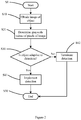
- FIG. 2 is a flow chart schematically showing a Raman spectrum detection method according to an embodiment of the present disclosure. As shown in Figure 2 , after starting the detection apparatus 100 (step S0), the detection method may further include following steps:
- the detection apparatus 100 ends (step S50) after the detection is finished or terminated.
- the detection may include a Raman spectrum detection to be implemented by using laser light from a laser to irradiate the object, or other detections to be implemented by using laser light to irradiate the object.
- the above steps may be specifically implemented in following ways.
- step S10 the image, for example, an optical image, of the object 120 to be detected may be obtained by the imaging device 140.
- an image processor may be used to process the image obtained by the imaging device 140 so as to obtain the grayscale value of each of the pixels in the image.
- the step S30 may further comprise:
- step S30 may further comprise:
- step S41 the controller 150 may instruct the laser 110 to emit laser light for implementing the Raman spectrum detection.
- step S42 the controller 150 may instruct the laser 110 to not emit laser light, to reduce a light emitting power of the laser, to shorten a time period of the laser for continuously emitting the laser light, or to terminate the detection operation. Further, the step S42 may further comprise instructing by the controller 150 an alarm device 160 to send an alarm signal.
- the mechanism of the subject of the present disclosure may be delivered as various forms of program products, and the exemplified embodiments of the subject of the present disclosure may be applicable independent of the specific types of the signal carrying media that perform the delivery in practice.
- the signal carrying media include, but not limited to: recordable media, such as a floppy disc, a hard disk drive, an optical disc (CD, DVD), a digital magnetic tape, a computer memory or the like; and transmission media such as digital and/or analogue communication media (for example, an optical fiber cable, a wave guide, a wired communication link, a wireless communication link or the like).
Landscapes
- Physics & Mathematics (AREA)
- Spectroscopy & Molecular Physics (AREA)
- General Physics & Mathematics (AREA)
- Health & Medical Sciences (AREA)
- Chemical & Material Sciences (AREA)
- Analytical Chemistry (AREA)
- Biochemistry (AREA)
- General Health & Medical Sciences (AREA)
- Life Sciences & Earth Sciences (AREA)
- Immunology (AREA)
- Pathology (AREA)
- Nuclear Medicine, Radiotherapy & Molecular Imaging (AREA)
- Engineering & Computer Science (AREA)
- Human Computer Interaction (AREA)
- Mathematical Physics (AREA)
- Theoretical Computer Science (AREA)
- Investigating, Analyzing Materials By Fluorescence Or Luminescence (AREA)
Abstract
Description
- This application claims the priority benefit of the Chinese Patent Application No.
201711442746.8 filed on December 26, 2017 - Embodiments of the present disclosure generally relate to a detection apparatus and a detection method, and particularly, to Raman spectrum detection apparatus and method based on image grayscale recognition.
- Raman spectrum analysis technology is a non-contact spectrum analysis technology based on Raman scattering effect, which can qualitatively and quantitatively analyze the composition of a substance. Raman spectrum is a molecular vibration spectrum that can reflect the fingerprint characteristics of molecules, and can be used for the inspection of substance. Raman spectrometer can inspect and identify the substance by the Raman spectrum generated from the Raman scattering effect of the object to be inspected with respect to exciting light.
- In recent years, Raman spectrum analysis technology has been widely used in the fields of dangerous goods inspection and substance identification. In the field of substance identification, because the colors and shapes of various substances are different from each other, it is usually hard for a person to accurately determine the properties of the substance. Raman spectrum is determined by the molecular energy level structure of the object to be inspected, thus the Raman spectrum can be used as the "fingerprint" information of a substance for substance identification. Therefore, Raman spectrum analysis technology has been widely used in the fields of customs, public safety, food & medicine, environment, etc.
- Laser having a high power density is generally used as an exciting light source in Raman spectrum detection, for example, near infrared laser light of 785nm has a stronger thermal effect, thus in case that components of the object to be detected are not known, an indiscreet detection made by using such laser light may possibly cause the object to be detected to be burned and damaged by the laser light. If the object to be detected is a flammable and explosive chemical, such indiscreet detection may lead to burning, exploding and the like, resulting in personal and property loss.
- An object of the present disclosure is to at least partly solve or alleviate at least one aspect of the above-mentioned and other disadvantages or problems in prior arts.
- According to an aspect of the present disclosure, there is provided a Raman spectrum detection apparatus based on image grayscale recognition.
- According to an exemplary embodiment, the detection apparatus may comprise: a laser configured to emit laser light to an object to be detected; an imaging device configured to obtain an image of the object; a Raman spectrometer configured to receive Raman light coming from the object and generated under irradiation of the laser light so as to obtain a Raman spectrum of the object; and a controller configured to control a detection operation of the detection apparatus based on grayscales of the image.
- According to another embodiment, the controller may be further configured to: determine, based on the image, a grayscale value of each of pixels of the image; compare the grayscale value of each of the pixels with a preset grayscale threshold; and control the detection operation of the detection apparatus based on a comparison result.
- According to another embodiment, the controller is further configured to: determine a percentage of the number of the pixels, grayscale values of which are smaller than the grayscale threshold, with respect to a total pixel number of the image; and compare the determined percentage with a preset percentage threshold, and control the detection operation of the detection apparatus based on a comparison result.
- According to another embodiment, the controller may be further configured to: determine, based on the image, a grayscale value of each of pixels of the image; calculate an average grayscale value of all pixels of the image based on the grayscale values of the pixels; and compare the average grayscale value with a preset average grayscale threshold, and control the detection operation of the detection apparatus based on a comparison result.
- According to a further embodiment, the detection apparatus may further comprise: a first beam splitter disposed in a Raman light path from the object to the Raman spectrometer, and configured to guide the laser light emitted from the laser to the object and to transmit therethrough the Raman light from the object to the Raman spectrometer. According to a further embodiment, the first beam splitter may include a long-wavelength pass dichroic mirror.
- According to a further embodiment, a second beam splitter disposed in a Raman light path from the object to the Raman spectrometer, and configured to reflect visible light from the object to the imaging device such that the object is imaged by the imaging device and to allow the laser light emitted from the laser and the Raman light from the object to pass therethrough. According to a further embodiment, the second beam splitter may include a long-wavelength pass dichroic mirror.
- According to a further embodiment, the detection apparatus may further comprise at least one of following optical members: a first optical filter disposed in the Raman light path at a position downstream of the first beam splitter and the second beam splitter, and configured to filter out Rayleigh light of a light signal; a second optical filter disposed between the laser and the first beam splitter and configured to limit a wavelength of the laser light emitted by the laser within a desired wavelength band; and a third optical filter disposed between the imaging device and the second beam splitter and configured to filter out laser light from the object.
- According to a further embodiment, the detection apparatus may further comprise at least one of following optical members: a first convergent lens or lens set disposed between the second beam splitter and the object; a second convergent lens or lens set disposed between the imaging device and the second beam splitter; and a third convergent lens or lens set disposed between the Raman spectrometer and the first beam splitter.
- It is noted that each of the first to third convergent lenses or lens sets described herein may include a single convex lens as shown in the drawings, or may include a lens set composed of a plurality of lens and having a light converging function.
- According to a further embodiment, the detection apparatus may further comprise a light source configured to illuminate the object.
- According to another aspect of the present disclosure, there is provided a method of detecting a Raman spectrum of an object based on image grayscale recognition.
- According to an exemplary embodiment, the method may comprise: obtaining an image of an object to be detected; determining a grayscale value of each of pixels of the image; determining, based on grayscale values of the pixels of the image, whether or not the object is adaptive to a Raman spectrum detection to be implemented by irradiating the object by laser light; implementing the Raman spectrum detection if it is determined the object is adaptive to the Raman spectrum detection; and if it is determined the object is not adaptive to the Raman spectrum detection, terminating the Raman spectrum detection, or adjusting a detection parameter for the Raman spectrum detection such that the object is adaptive to the Raman spectrum detection with the adjusted detection parameter.
- According to another embodiment, the step of determining, based on grayscale values of the pixels of the image, whether or not the object is adaptive to a Raman spectrum detection to be implemented by irradiating the object by laser light may comprise: comparing the grayscale value of each of the pixels with a preset grayscale threshold so as to determine a deep-colored pixel percentage of the image, which is a percentage of the number of the pixels with grayscale values smaller than the grayscale threshold, with respect to a total pixel number of the image; and comparing the deep-colored pixel percentage with a preset percentage threshold, and concluding that the object is not adaptive to the Raman spectrum detection if the deep-colored pixel percentage is larger than the threshold percentage, and that the object is adaptive to the Raman spectrum detection if the deep-colored pixel percentage is smaller than or equal to the threshold percentage.
- According to another embodiment, the step of determining, based on grayscale values of the pixels of the image, whether or not the object is adaptive to a Raman spectrum detection to be implemented by irradiating the object by laser light may comprise: calculating an average grayscale value of all pixels of the image; and comparing the average grayscale value with a preset average grayscale threshold, and concluding that the object is not adaptive to the Raman spectrum detection if the average grayscale value is smaller than the average grayscale value, and that the object is adaptive to the Raman spectrum detection if the average grayscale value is greater than or equal to the average grayscale value.
- According to another embodiment, the method may further comprise: sending an alarm signal if it is determined that the object is not adaptive to the Raman spectrum detection.
- According to another embodiment, adjusting a detection parameter for the Raman spectrum detection includes: reducing light emitting power of the laser for generating the laser light; and/or shortening a time period of the laser for continuously emitting the laser light.
- Exemplary embodiments of the present disclosure will be described as examples with reference to the accompanying drawings, in which:
-
Figure 1 is a block diagram schematically showing a detection apparatus according to an embodiment of the present disclosure; and -
Figure 2 is a flow chart schematically showing a detection method according to another embodiment of the present disclosure. - Exemplary embodiments of the present disclosure will be described hereinafter in detail with reference to the attached drawings. Throughout the description, like reference numerals refer to like elements. The present disclosure may, however, be embodied in many different forms and should not be construed as being limited to the embodiments set forth herein; rather, these embodiments are provided so that the present disclosure will be thorough and complete, and will fully convey the concept of the disclosure to those skilled in the art.
- According to a general inventive concept of the present disclosure, there is provided a detection apparatus, comprising: a laser configured to emit laser light to an object to be detected; a Raman spectrometer configured to receive Raman light from the object; an imaging device configured to obtain an image of the object; and a controller configured to control an operation of the detection apparatus based on grayscales of the image.
-
Figure 1 is a schematic diagram of a detection apparatus according to an embodiment of the present disclosure. As shown inFigure 1 , in this embodiment, adetection apparatus 100 comprises: alaser 110 configured to emit laser light 111 towards anobject 120 to be detected; a Ramanspectrometer 130 configured to receive a Raman light signal 112 generated from theobject 120 under the irradiation of the laser light; animaging device 140 configured to obtain or capture an image of theobject 120; and acontroller 150 configured to control an operation of thedetection apparatus 100 based on grayscales of the image - In order to excite Raman scattering effect from an object to be detected, laser light emitted by a laser generally has a higher power density, which will generate a stronger thermal effect; if the color of the object to be detected is deeper (for example, dark gray, black or the like), the object will absorb more laser light and thereby increase rapidly in its surface temperature, which may cause the object to be partially ablated, or even exploded if the object is gunpower. If an inspector is inadequately trained or careless, the above phenomena may occur, or even the field inspector may be damaged. In order to avoid the above phenomena, technique schemes of the present disclosure provide an imaging device for obtaining an image of the object to be detected, such as an optical image, determine whether or not the object to be detected is deep colored or black, and determine a subsequent detection operation based on the determined color shade of the object.
- The
imaging device 140 may include a CCD imaging device, a CMOS imaging device or other known imaging devices or a light sensor. The image of the object may be an image of the whole of the object obtained in a certain direction, or an image of a detected portion of the object, which depends on the dimensions of theobject 120 to be detected, parameters of thedetection apparatus 100 such as a detection area, For example, if the object to be detected is a gemstone having a very small size, the imaging device may obtain an image of the whole of one side face of the object; if the object to be detected has a larger size, the imaging device may image partially a portion to be detected of the object. Herein, "color of an object" may be a color of the whole of a detected face of the object, or may be a color of a partial part of the detected portion of the object. - In embodiments of the present disclosure, a color shade of an object may be determined according to grayscales of an image of the object. According to an exemplary embodiment, the
controller 150 is configured to: determine, based on the image obtained by theimaging device 140, a grayscale value of each of pixels of the image, compare the grayscale value of each of the pixels with a preset grayscale threshold, and control the detection operation of the detection apparatus based on a comparison result. In some examples, thecontroller 150 may determine a percentage of the number of the pixels, grayscale values of which are smaller than the grayscale threshold, relative to a total pixel number of the image, compare the determined percentage with a preset percentage threshold, and control the detection operation of thedetection apparatus 100 based on a comparison result. - For example, a grayscale processing operation may be made by using an image processor on the image of the object obtained by the imaging device, so as to obtain the grayscale value (a value from 0 to 255) of each of pixels of the image. In an example, the image processor may be integrated into the imaging device 140 (that is, the
imaging device 140 comprises the image processor); in another example, the image processor may also be integrated into the controller 150 (that is, thecontroller 150 comprises the image processor); in other examples, the image processor may also be provided in a field operated computer or in a remote control center. In an alternative embodiment, grayscale processing of the images of the object to be detected may be implemented by software or algorithms stored in a storage device of a field operated computer, of a computer in a remote control center or of thecontroller 150 so as to obtain grayscale values of respective pixels of the image. - Generally, a smaller grayscale value represents that the object has a deeper color, thus the grayscale threshold may be set based on actual conditions or requirements. For example, in an exemplary embodiment, the grayscale threshold may be set as 30, more or less. The
controller 150 may compare the grayscale value of each of the pixels in the image of object with the preset grayscale threshold, so as to determine a percentage (hereinafter referred to as "deep-colored pixel percentage") of the number of the pixels, grayscale values of which are smaller than the grayscale threshold, relative to a total pixel number of the image. It will be understood that if the grayscale values of all or most of the pixels are smaller than the grayscale threshold, it shows that the color of the object appearing on the image is deeper. The threshold percentage may be set according to actual requirements (For example, the threshold percentage is set as 85%, 90% or 95%), and the deep-colored pixel percentage determined in above step may be compared with the threshold percentage, so that thedetection apparatus 100 is controlled based on the comparison result. - For example, in case that the threshold percentage is set as 85%, if the
controller 150 determines that the grayscale values of 85% or more of the pixels in the image are smaller than the grayscale threshold (that is, the deep-colored pixel percentage is greater than or equal to 85%), thecontroller 150 can conclude that the object to be detected has a deeper color and is not adaptive to a detection operation, and then instruct thelaser 110 to not emit laser light, to reduce a light emitting power of the laser, to shorten a time period of the laser for continuously emitting the laser light, or to terminate the detection operation. In a further embodiment, thedetection apparatus 100 may further comprise analarm device 160, and thecontroller 150 may be further configured to control an operation of thealarm device 160 based on the comparison result between the deep-colored pixel percentage and the threshold percentage. For example, if thecontroller 150 determines that the deep-colored pixel percentage is greater than the threshold percentage, it may instruct thealarm device 160 to send an alarm signal so as to warn a related operator that the current object to be detected is not adaptive to be detected due to its deeper color and/or that the current detection operation has been terminated. The alarm signal may include at least of a special acoustical signal and an image signal. - If the deep-colored pixel percentage is smaller than or equal to the threshold percentage, the
controller 150 may conclude that the color shade of the current object to be detected is adaptive to a detection operation. In such a case, thecontroller 150 may instruct thelaser 110 to emit laser light, for implementing subsequent detection operation. - According to another exemplary embodiment, the
controller 150 may also be configured to: determine, based on the image, a grayscale value of each of pixels of the image; calculate an average grayscale value of all pixels of the image based on the grayscale values of the pixels; and compare the average grayscale value with a preset average grayscale threshold, and control the detection operation of the detection apparatus based on a comparison result. - For example, the average grayscale threshold may be set as 25 or may be set as other values according to actual requirements. If the average grayscale value of all pixels in the image is smaller than 25, the
controller 150 may conclude the image, as a whole, has a deeper color and thus is not adaptive to a detection operation. In this case, thecontroller 150 may instruct thelaser 110 to not emit laser light, to reduce a light emitting power of the laser, to shorten a time period of the laser for continuously emitting the laser light, or to terminate the detection operation, and meanwhile, may instruct thealarm device 160 to send an alarm signal so as to warn a related operator that the current object is not adaptive to be detected and/or that the detection operation has been terminated. If the average grayscale value is greater than or equal to the average grayscale threshold, thecontroller 150 may conclude the color shade of the object is adaptive to a detection operation. In such a case, thecontroller 150 may instruct thelaser 110 to emit laser light, for implementing subsequent detection operation. - In other embodiments, the color shade of the object to be detected may be judged by means of other known means in prior arts, and then the detection operation of the
detection apparatus 100 is controlled based on the judgment result. - According to an embodiment of the present disclosure, the
detection apparatus 100 may further comprise one or more optical devices for configuring or guiding a light path between thelaser 110 and theobject 120 to be detected (hereinafter referred to as "laser light path"), a light path between theobject 120 to be detected and the Raman spectrometer 130 (hereinafter referred to as "Raman light path"), and/or a light path between theimaging device 140 and theobject 120 to be detected (hereinafter referred to as "imaging light path"). - As shown in
Figure 1 , the optical devices may include afirst beam splitter 161 disposed in the Raman light path and configured to guide the laser light emitted from thelaser 110 to theobject 120 to be detected and to not block or adversely affect transmission of a light signal (Raman scattering light) from theobject 120 to be detected to theRaman spectrometer 130. - As an example, the
first beam splitter 161 may be a long-wavelength pass dichroic mirror. Long-wavelength pass dichroic mirror generally allows light having a wavelength greater than a predetermined wavelength to pass therethrough and reflects light having a wavelength smaller than the predetermined wavelength. In a case where a Raman scattering effect is excited by using laser light to irradiate the object to be detected, most of the Raman scattering light will decrease in frequency and increase in wavelength. Thus, the long-wavelength pass dichroic mirror may be suitably configured such that laser light emitted from thelaser 110 and having a predetermined wavelength will be reflected towards theobject 120 to be detected and that Raman scattering light coming from theobject 120 to be detected and having an increased wavelength will be allowed to pass through the long-wavelength pass dichroic mirror to be transmitted towards theRaman spectrometer 130. Specific configuration of the long-wavelength pass dichroic mirror may be set according the wavelength of the laser light emitted by thelaser 110. - Although in above examples, the long-wavelength pass dichroic mirror is described as an example of the
first beam splitter 161, thefirst beam splitter 161 of the present disclosure is not only limited to the long-wavelength pass dichroic mirror, and the above function may be achieved by selecting the beam splitting member based on other known wavelength. - With provision of the
first beam splitter 161, the laser light path and the Raman light path may be at least partly combined, thereby facilitating reduction of the overall dimension of the detection apparatus. - Further, as shown in
Figure 1 , the optical devices may further comprise asecond beam splitter 162, which is also disposed in the Raman light path and further configured to reflect visible light from the object to theimaging device 140 such that the object to be detected is imaged by theimaging device 140 and to allow the laser light emitted from thelaser 110 and the Raman light from theobject 120 to be detected to pass therethrough. - As an example, the
second beam splitter 162 may also include a long-wavelength pass dichroic mirror. For example, if near-infrared laser light having a wavelength of 785 nm is used (that is, thelaser 110 is configured to emit near-infrared laser light having a wavelength of 785 nm), and if a long-wavelength pass dichroic mirror is used as thesecond beam splitter 162, thesecond beam splitter 162 may reflect visible light, which generally having a wavelength in a range from 400 nm to 760 nm (or a range from 380 nm to 780 nm for a few people), while allowing infrared light having a wavelength greater than that of the visible light to pass therethrough. As such, imaging, by theimaging device 140, of the object to be detected will not be affected, and transmission of the laser light emitted by thelaser 110 and the Raman scattering light from theobject 120 to be detected will also not be affected. Specific threshold of the long-wavelength pass dichroic mirror may be set or configured as required (for example, based on parameters such as the wavelength of the laser light). In embodiments of the present disclosure, thesecond beam splitter 162 is not limited to the long-wavelength pass dichroic mirror, and the above function of thesecond beam splitter 162 may be achieved by selecting other known beam splitting members. - With provision of the
second beam splitter 162, the imaging light path and the Raman light path may be at least partly combined, thereby facilitating reduction of the overall dimension of the detection apparatus. - It is noted that in the above embodiments, operational principle of the present disclosure are only described by way of examples, but the present disclosure is not limited to the above exemplary embodiment, and the
first beam splitter 161 and thesecond beam splitter 162 are also not limited to the long-wavelength pass dichroic mirror. For example, in another embodiment, thelaser 110 emits ultraviolet laser light, and in this case, thefirst beam splitter 161 is a long-wavelength pass dichroic mirror, while thesecond beam splitter 162 may be a short-wave pass dichroic mirror. - As shown in
Figure 1 , in the Raman light path, thesecond beam splitter 162 is arranged closer to theobject 120 to be detected than the first beam splitter 161(that is, thesecond beam splitter 162 is arranged at an upstream side of the Raman light path, while thefirst beam splitter 161 is arranged at a downstream side of the Raman light path). However, the present disclosure is not limited to this specific arrangement. For example, if thelaser 110 emits ultraviolet laser light, thesecond beam splitter 162 may be arranged at the downstream side of the Raman light path relative to the first beam splitter 1261, and thesecond beam splitter 162 may be a short-wave pass dichroic mirror. In any case, it is ok as long as most of the visible light is reflected by thesecond beam splitter 162 and most of the Raman light is transmitted through thesecond beam splitter 162. - In another embodiment, the optical devices may further include one or more other optical members, in addition to the
first beam splitter 161 and thesecond beam splitter 162. - For example, as shown in
Figure 1 , thedetection apparatus 100 may further comprise a firstoptical filter 163 disposed in the Raman light path at a position downstream of thefirst beam splitter 161 and configured to filter out Rayleigh light or other stray light from a light signal having passed through thefirst beam splitter 161, thereby reducing interference of the Rayleigh light or other stray light to the Raman spectrometer. In an exemplary embodiment, the firstoptical filter 163 may include a long wave-pass filter or a notch filter. - In a further embodiment, as shown in
Figure 1 , thedetection apparatus 100 may further comprise a secondoptical filter 164 disposed in the laser light path at a position upstream of the first beam splitter 161 (that is, between thelaser 110 and the first beam splitter 161) and configured to limit a wavelength of the laser light emitted by thelaser 110 within a desired wavelength band. In an exemplary embodiment, the secondoptical filter 164 may include a narrow band filter. - In a further embodiment, as shown in
Figure 1 , thedetection apparatus 100 may further comprise a thirdoptical filter 165 disposed in the imaging light path at a position downstream of the second beam splitter 162 (that is, between thesecond beam splitter 162 and the imaging device 140) and configured to filter out stray laser light from theobject 120, thereby avoiding unnecessary interference or damage to the imaging device. In an exemplary embodiment, for example, the thirdoptical filter 165 may include a notch filter configured for filtering out stray light of the laser light during detection operation of thedetection apparatus 100 so as to avoid the stray light entering and damaging theimaging device 140. - In a further embodiment, as shown in
Figure 1 , thedetection apparatus 100 may further comprise a first convergent lens or lens set 166 disposed between thesecond beam splitter 162 and theobject 120 to be detected, a second convergent lens or lens set 167 disposed between theimaging device 140 and thesecond beam splitter 162, and/or a third convergent lens or lens set 168 disposed between theRaman spectrometer 130 and thefirst beam splitter 161. The first convergent lens or lens set 166 may be used for imaging of theobject 120 by theimaging device 140, and also for collecting scattered Raman light from theobject 120 such that more scattered Raman light may be transmitted to the Raman spectrometer, thereby facilitating improvement of sensitivity and accuracy of detection of thedetection apparatus 100. The second convergent lens or lens set 167 may be used for imaging of theobject 120 by theimaging device 140. The third convergent lens or lens set 168 may be used for converging light such that more scattered Raman light may be converged into the Raman spectrometer, thereby facilitating improvement of sensitivity and accuracy of detection of thedetection apparatus 100. - Further, according to another embodiment, as shown in
Figure 1 , thedetection apparatus 100 may further comprise alighting device 170 configured to provide illumination to theobject 120 to be detected. Generally, thedetection apparatus 100 has a detection end, and theobject 120 to be detected is positioned closer to the detection end, and thus it is not possible to provide sufficient illumination to a portion to be detected of theobject 120 by an external light source. Provision or integration of thelighting device 170 within thedetection apparatus 100 will be favorable for theimaging device 140 to obtain a clear image of theobject 120 to be detected. Thelighting device 170 may be provided within thedetection apparatus 100 at a position close to the detection end; for example, as shown inFigure 1 , thelighting device 170 may be arranged between thesecond beam splitter 162 and theobject 120 to be detected, at a position upstream or downstream of the first convergent lens orlens set 166. In other embodiments, the lighting device may also be arranged at any suitable positions within thedetection apparatus 100. Thelighting device 170 may include, for example, one or more LED lamps. - According to another aspect of the present disclosure, there is further provided a detection method.
-
Figure 2 is a flow chart schematically showing a Raman spectrum detection method according to an embodiment of the present disclosure. As shown inFigure 2 , after starting the detection apparatus 100 (step S0), the detection method may further include following steps: - step S10: obtaining an image of an object to be detected;
- step S20: determining a grayscale value of each of pixels of the image;
- step S30: determining, based on grayscale values of the pixels of the image, whether or not the object is adaptive to the detection;
- step S41: implementing the detection if it is determined the object is adaptive to the detection; and
- step S42: if it is determined the object is not adaptive to the detection, terminating the detection.
- The operation of the
detection apparatus 100 ends (step S50) after the detection is finished or terminated. Exemplarily, the detection may include a Raman spectrum detection to be implemented by using laser light from a laser to irradiate the object, or other detections to be implemented by using laser light to irradiate the object. - In an exemplary embodiment, the above steps may be specifically implemented in following ways.
- In step S10, the image, for example, an optical image, of the
object 120 to be detected may be obtained by theimaging device 140. - In step S20, an image processor may be used to process the image obtained by the
imaging device 140 so as to obtain the grayscale value of each of the pixels in the image. - The step S30 may further comprise:
- S31: comparing the grayscale value of each of the pixels with a preset grayscale threshold so as to determine a percentage (that is, a deep-colored pixel percentage) of the number of the pixels, grayscale values of which are smaller than the grayscale threshold, relative to a total pixel number of the image; and
- S32: comparing the deep-colored pixel percentage with a preset percentage threshold, and concluding that the object is not adaptive to the detection if the deep-colored pixel percentage is larger than the threshold percentage, and that the object is adaptive to the detection if the deep-colored pixel percentage is smaller than or equal to the threshold percentage.
- In an alternative embodiment, the step S30 may further comprise:
- S31': calculating an average grayscale value of all pixels of the image; and
- S32': comparing the average grayscale value with a preset average grayscale threshold, and concluding that the object is not adaptive to the Raman spectrum detection if the average grayscale value is smaller than the average grayscale threshold, and that the object is adaptive to the Raman spectrum detection if the average grayscale value is greater than or equal to the average grayscale threshold.
- In step S41, the
controller 150 may instruct thelaser 110 to emit laser light for implementing the Raman spectrum detection. - In step S42, the
controller 150 may instruct thelaser 110 to not emit laser light, to reduce a light emitting power of the laser, to shorten a time period of the laser for continuously emitting the laser light, or to terminate the detection operation. Further, the step S42 may further comprise instructing by thecontroller 150 analarm device 160 to send an alarm signal. - The above detailed description has explained various embodiments of the above Raman spectrum inspection apparatus and monitoring method thereof by schematic views, flow charts and/or examples. In case that the schematic views, flow charts and/or examples each include one or more functions and/or operations, the skilled person in the art should understand that each function and/or operation in such schematic views, flow charts and/or examples may be implemented separately and/or collectively by various structures, hardware, software, firmware or any combination of them in essential. In an embodiment, some parts of the subject of the embodiment of the present disclosure may be implemented by Application Specific Integrated Circuits (ASIC), Field Programmable Gate Arrays (FPGA), Digital Signal Processors (DSP) or other integrated forms. However, the skilled person in the art should understand that some aspects of the embodiments disclosed herein may be implemented equally in the integrated circuit entirely or partly, implemented as one or more computer programs running on one or more computers (for example, implemented as one or more programs running on one or more computer systems), implemented as one or more programs running on one or more processors (for example, implemented as one or more programs running on one or more microprocessors), implemented as firmware, or implemented as any combination of the above methods in essential. From the present disclosure, the skilled person in the art has capability of designing circuits and/or writing software and/or firmware codes. Furthermore, the skilled person in the art will appreciate that the mechanism of the subject of the present disclosure may be delivered as various forms of program products, and the exemplified embodiments of the subject of the present disclosure may be applicable independent of the specific types of the signal carrying media that perform the delivery in practice. Examples of the signal carrying media include, but not limited to: recordable media, such as a floppy disc, a hard disk drive, an optical disc (CD, DVD), a digital magnetic tape, a computer memory or the like; and transmission media such as digital and/or analogue communication media (for example, an optical fiber cable, a wave guide, a wired communication link, a wireless communication link or the like).
- Although exemplary embodiments of the present disclosure have been illustrated in the drawings, it will be understood by those skilled in the art that the present disclosure may be still implemented even if one or more unnecessary members/parts are omitted. Although several exemplary embodiments of the present disclosure have been described with reference to the drawings, it would be appreciated by those skilled in the art that modifications and variations may be made in these embodiments without departing from the principles and spirit of the general inventive concept of the present disclosure, the scope of which is defined in the appended claims and their equivalents.
Claims (16)
- A Raman spectrum detection apparatus, comprising:a laser configured to emit laser light to an object to be detected;an imaging device configured to obtain an image of the object;a Raman spectrometer configured to receive Raman light coming from the object and generated under irradiation of the laser light so as to obtain a Raman spectrum of the object; anda controller configured to control a detection operation of the detection apparatus based on grayscales of the image.
- The detection apparatus according to claim 1, wherein the controller is further configured to:determine, based on the image, a grayscale value of each of pixels of the image;compare the grayscale value of each of the pixels with a preset grayscale threshold; andcontrol the detection operation of the detection apparatus based on a comparison result.
- The detection apparatus according to claim 2, wherein the controller is further configured to:determine a percentage of the number of the pixels, grayscale values of which are smaller than the grayscale threshold, with respect to a total pixel number of the image; andcompare the determined percentage with a preset percentage threshold, and control the detection operation of the detection apparatus based on a comparison result.
- The detection apparatus according to claim 1, wherein the controller is further configured to:determine, based on the image, a grayscale value of each of pixels of the image;calculate an average grayscale value of all pixels of the image based on the grayscale values of the pixels; andcompare the average grayscale value with a preset average grayscale threshold, and control the detection operation of the detection apparatus based on a comparison result.
- The detection apparatus according to any one of claims 1-4, wherein the detection apparatus further comprises:
a first beam splitter disposed in a Raman light path from the object to the Raman spectrometer, and configured to guide the laser light emitted from the laser to the object and to transmit therethrough the Raman light from the object to the Raman spectrometer. - The detection apparatus according to claim 5, wherein the first beam splitter includes a long-wavelength pass dichroic mirror.
- The detection apparatus according to claim 4, wherein the detection apparatus further comprises:
a second beam splitter disposed in a Raman light path from the object to the Raman spectrometer, and configured to reflect visible light from the object to the imaging device such that the object is imaged by the imaging device and to allow the laser light emitted from the laser and the Raman light from the object to pass therethrough. - The detection apparatus according to claim 7, wherein the second beam splitter includes a long-wavelength pass dichroic mirror.
- The detection apparatus according to claim 7, wherein the detection apparatus further comprises at least one of following optical members:a first optical filter disposed in the Raman light path at a position downstream of the first beam splitter and the second beam splitter, and configured to filter out Rayleigh light of a light signal;a second optical filter disposed between the laser and the first beam splitter and configured to limit a wavelength of the laser light emitted by the laser within a desired wavelength band; anda third optical filter disposed between the imaging device and the second beam splitter and configured to filter out laser light from the object.
- The detection apparatus according to claim 7, wherein the detection apparatus further comprises at least one of following optical members:a first convergent lens or lens set disposed between the second beam splitter and the object;a second convergent lens or lens set disposed between the imaging device and the second beam splitter; anda third convergent lens or lens set disposed between the Raman spectrometer and the first beam splitter.
- The detection apparatus according to any one of claims 1-10, wherein the detection apparatus further comprises:
a light source configured to illuminate the object. - A method of detecting a Raman spectrum of an object, comprising steps of:obtaining an image of an object to be detected;determining a grayscale value of each of pixels of the image;determining, based on grayscale values of the pixels of the image, whether or not the object is adaptive to a Raman spectrum detection to be implemented by irradiating the object by laser light;implementing the Raman spectrum detection if it is determined that the object is adaptive to the Raman spectrum detection; andif it is determined the object is not adaptive to the Raman spectrum detection, terminating the Raman spectrum detection, or adjusting a detection parameter for the Raman spectrum detection such that the object is adaptive to the Raman spectrum detection with the adjusted detection parameter.
- The method according to claim 12, wherein the step of determining, based on grayscale values of the pixels of the image, whether or not the object is adaptive to a Raman spectrum detection to be implemented by irradiating the object by laser light comprises:comparing the grayscale value of each of the pixels with a preset grayscale threshold so as to determine a deep-colored pixel percentage of the image, which is a percentage of the number of the pixels with grayscale values smaller than the grayscale threshold, with respect to a total pixel number of the image; andcomparing the deep-colored pixel percentage with a preset percentage threshold, and concluding that the object is not adaptive to the Raman spectrum detection if the deep-colored pixel percentage is larger than the preset percentage threshold, and that the object is adaptive to the Raman spectrum detection if the deep-colored pixel percentage is smaller than or equal to the preset percentage threshold.
- The method according to claim 12 or 13, wherein the step of determining, based on grayscale values of the pixels of the image, whether or not the object is adaptive to a Raman spectrum detection to be implemented by irradiating the object by laser light comprises:calculating an average grayscale value of all pixels of the image; andcomparing the average grayscale value with a preset average grayscale threshold, and concluding that the object is not adaptive to the Raman spectrum detection if the average grayscale value is smaller than the preset average grayscale threshold, and that the object is adaptive to the Raman spectrum detection if the average grayscale value is greater than or equal to the preset average grayscale threshold.
- The method according to any one of claims 12-14, further comprising:
sending an alarm signal if it is determined that the object is not adaptive to the Raman spectrum detection. - The method according to any one of claims 12-15, wherein the step of adjusting a detection parameter for the Raman spectrum detection comprises:reducing light emitting power of the laser for generating the laser light; and/orshortening a time period of the laser for continuously emitting the laser light.
Applications Claiming Priority (2)
| Application Number | Priority Date | Filing Date | Title |
|---|---|---|---|
| CN201711442746.8A CN107991287B (en) | 2017-12-26 | 2017-12-26 | Raman spectrum detection equipment and method based on image grayscale recognition |
| PCT/CN2018/122123 WO2019128808A1 (en) | 2017-12-26 | 2018-12-19 | Image gray scale recognition-based raman spectrum detection apparatus and method |
Publications (2)
| Publication Number | Publication Date |
|---|---|
| EP3531111A1 true EP3531111A1 (en) | 2019-08-28 |
| EP3531111A4 EP3531111A4 (en) | 2020-11-18 |
Family
ID=62041967
Family Applications (1)
| Application Number | Title | Priority Date | Filing Date |
|---|---|---|---|
| EP18826176.2A Pending EP3531111A4 (en) | 2017-12-26 | 2018-12-19 | GRAY SCALE DETECTION BASED RAMAN SPECTRUM DETECTOR AND METHOD |
Country Status (4)
| Country | Link |
|---|---|
| US (1) | US10852187B2 (en) |
| EP (1) | EP3531111A4 (en) |
| CN (1) | CN107991287B (en) |
| WO (1) | WO2019128808A1 (en) |
Families Citing this family (5)
| Publication number | Priority date | Publication date | Assignee | Title |
|---|---|---|---|---|
| CN107860761B (en) * | 2017-12-26 | 2020-12-11 | 同方威视技术股份有限公司 | Raman spectroscopic detection equipment and sample safety detection method for Raman spectroscopic detection |
| CN107991287B (en) * | 2017-12-26 | 2023-11-10 | 同方威视技术股份有限公司 | Raman spectrum detection equipment and method based on image grayscale recognition |
| CN110530846A (en) * | 2019-09-19 | 2019-12-03 | 北京华泰诺安探测技术有限公司 | A kind of laser Raman spectroscopy detection system and its detection method |
| EP3919550B1 (en) * | 2020-06-02 | 2025-05-07 | Evonik Operations GmbH | Linear acetoxy group bearing siloxanes and secondary products |
| CN112986154A (en) * | 2021-02-03 | 2021-06-18 | 重庆神华薄膜太阳能科技有限公司 | Float glass tin surface detection device and detection method |
Family Cites Families (17)
| Publication number | Priority date | Publication date | Assignee | Title |
|---|---|---|---|---|
| US7224825B2 (en) * | 2002-04-18 | 2007-05-29 | Lockheed Martin Corporation | Detecting and identifying hazardous substances contained in mail articles |
| US7535002B2 (en) * | 2004-12-03 | 2009-05-19 | Fluke Corporation | Camera with visible light and infrared image blending |
| JP4887989B2 (en) * | 2005-12-02 | 2012-02-29 | ナノフォトン株式会社 | Optical microscope and spectrum measuring method |
| US7508524B2 (en) * | 2007-07-20 | 2009-03-24 | Vanderbilt University | Combined raman spectroscopy-optical coherence tomography (RS-OCT) system and applications of the same |
| US9329084B2 (en) * | 2013-11-14 | 2016-05-03 | Thermo Scientific Portable Analytical Instruments Inc. | Moving laser focus in a spectrometer |
| US9400271B2 (en) * | 2013-12-18 | 2016-07-26 | Thermo Scientific Portable Analytical Instruments Inc. | Method and apparatus for temperature control during sample analysis |
| CN205941340U (en) * | 2016-01-25 | 2017-02-08 | 苑高强 | Material identifier and thing networking |
| CN105606542A (en) * | 2016-03-08 | 2016-05-25 | 京东方科技集团股份有限公司 | Color identification device and color identification method |
| CN105890764B (en) * | 2016-03-31 | 2018-01-23 | 杭州市农业科学研究院 | The method of the resolution flower color depth based on Computer Image Processing |
| CN206479455U (en) * | 2016-12-26 | 2017-09-08 | 同方威视技术股份有限公司 | Raman spectrum detection device |
| CN106770176A (en) * | 2016-12-26 | 2017-05-31 | 同方威视技术股份有限公司 | The method for safety monitoring of Raman spectrum testing equipment and Raman spectrum testing equipment |
| CN106770168B (en) * | 2016-12-26 | 2023-11-14 | 同方威视技术股份有限公司 | Item inspection equipment and methods based on Raman spectroscopy |
| CN107995949B (en) * | 2017-11-07 | 2020-07-10 | 深圳达闼科技控股有限公司 | Transmission power control method, device, storage medium and electronic device |
| CN107907527B (en) * | 2017-12-26 | 2023-10-13 | 同方威视技术股份有限公司 | Raman spectrum detection equipment and method based on reflected light power and image recognition |
| CN108020320B (en) * | 2017-12-26 | 2023-08-29 | 同方威视技术股份有限公司 | Raman spectrum detection equipment and method based on image recognition |
| CN107991287B (en) * | 2017-12-26 | 2023-11-10 | 同方威视技术股份有限公司 | Raman spectrum detection equipment and method based on image grayscale recognition |
| CN207923719U (en) * | 2017-12-26 | 2018-09-28 | 同方威视技术股份有限公司 | Raman spectrum detection device based on gradation of image identification |
-
2017
- 2017-12-26 CN CN201711442746.8A patent/CN107991287B/en active Active
-
2018
- 2018-12-19 WO PCT/CN2018/122123 patent/WO2019128808A1/en not_active Ceased
- 2018-12-19 US US16/313,690 patent/US10852187B2/en not_active Expired - Fee Related
- 2018-12-19 EP EP18826176.2A patent/EP3531111A4/en active Pending
Also Published As
| Publication number | Publication date |
|---|---|
| CN107991287B (en) | 2023-11-10 |
| US20190219446A1 (en) | 2019-07-18 |
| US10852187B2 (en) | 2020-12-01 |
| EP3531111A4 (en) | 2020-11-18 |
| CN107991287A (en) | 2018-05-04 |
| WO2019128808A1 (en) | 2019-07-04 |
Similar Documents
| Publication | Publication Date | Title |
|---|---|---|
| US10852187B2 (en) | Raman spectrum detection apparatus and method based on image grayscale recognition | |
| US20200088645A1 (en) | Raman spectrum inspection apparatus and method of monitoring detection security of the same | |
| US10260949B2 (en) | Raman spectrum-based object inspection apparatus and method | |
| EP3505915B1 (en) | Raman spectrum detection apparatus and method based on power of reflected light and image recognition | |
| JP6420807B2 (en) | Methods for wavelength spectrum analysis for detecting various gases using processed tapes | |
| EP3531112B1 (en) | Raman spectroscopy detection device and sample safety detection method for use in raman spectroscopy detection | |
| WO2014192734A1 (en) | Film thickness measurement method, film thickness measurement device, and recording medium | |
| JP6436664B2 (en) | Substrate inspection apparatus and substrate inspection method | |
| KR20220014323A (en) | Apparatus, corresponding methods and computer program products for performing quality control on an industrial production line | |
| US10823678B2 (en) | Raman spectrum detection apparatus and method based on power of reflected light | |
| CN108020320B (en) | Raman spectrum detection equipment and method based on image recognition | |
| JP5298684B2 (en) | Foreign object detection device and detection method | |
| CN207779900U (en) | Raman spectrum detection device based on reflected optical power and image recognition | |
| CN207923719U (en) | Raman spectrum detection device based on gradation of image identification | |
| US11946805B2 (en) | Spectrometer apparatus and a corresponding method for operating a spectrometer apparatus | |
| CN207779898U (en) | Raman spectrum detection device | |
| CN208488174U (en) | Raman spectrum detection device based on image recognition | |
| CN207779902U (en) | Raman spectrum detection device based on reflected optical power | |
| KR102868276B1 (en) | Apparatus and method for providing gas concentration | |
| WO2024085188A1 (en) | Measurement system, meat cutting system, measurement method and program |
Legal Events
| Date | Code | Title | Description |
|---|---|---|---|
| STAA | Information on the status of an ep patent application or granted ep patent |
Free format text: STATUS: UNKNOWN |
|
| STAA | Information on the status of an ep patent application or granted ep patent |
Free format text: STATUS: THE INTERNATIONAL PUBLICATION HAS BEEN MADE |
|
| PUAI | Public reference made under article 153(3) epc to a published international application that has entered the european phase |
Free format text: ORIGINAL CODE: 0009012 |
|
| STAA | Information on the status of an ep patent application or granted ep patent |
Free format text: STATUS: REQUEST FOR EXAMINATION WAS MADE |
|
| 17P | Request for examination filed |
Effective date: 20181228 |
|
| AK | Designated contracting states |
Kind code of ref document: A1 Designated state(s): AL AT BE BG CH CY CZ DE DK EE ES FI FR GB GR HR HU IE IS IT LI LT LU LV MC MK MT NL NO PL PT RO RS SE SI SK SM TR |
|
| AX | Request for extension of the european patent |
Extension state: BA ME |
|
| RIN1 | Information on inventor provided before grant (corrected) |
Inventor name: ZUO, JIAQIAN Inventor name: ZHANG, JIANHONG Inventor name: WANG, HONGQIN Inventor name: LIU, HAIHUI |
|
| R17P | Request for examination filed (corrected) |
Effective date: 20181228 |
|
| A4 | Supplementary search report drawn up and despatched |
Effective date: 20201015 |
|
| RIC1 | Information provided on ipc code assigned before grant |
Ipc: G01J 3/02 20060101ALI20201009BHEP Ipc: G01J 3/44 20060101ALI20201009BHEP Ipc: G01N 21/65 20060101AFI20201009BHEP Ipc: G01N 21/27 20060101ALI20201009BHEP |
|
| DAV | Request for validation of the european patent (deleted) | ||
| DAX | Request for extension of the european patent (deleted) |