EP3531109A1 - Active real-time characterization system providing spectrally broadband characterization - Google Patents
Active real-time characterization system providing spectrally broadband characterization Download PDFInfo
- Publication number
- EP3531109A1 EP3531109A1 EP19157847.5A EP19157847A EP3531109A1 EP 3531109 A1 EP3531109 A1 EP 3531109A1 EP 19157847 A EP19157847 A EP 19157847A EP 3531109 A1 EP3531109 A1 EP 3531109A1
- Authority
- EP
- European Patent Office
- Prior art keywords
- camera
- visible light
- light
- under test
- article under
- Prior art date
- Legal status (The legal status is an assumption and is not a legal conclusion. Google has not performed a legal analysis and makes no representation as to the accuracy of the status listed.)
- Pending
Links
Images


Classifications
-
- G—PHYSICS
- G01—MEASURING; TESTING
- G01N—INVESTIGATING OR ANALYSING MATERIALS BY DETERMINING THEIR CHEMICAL OR PHYSICAL PROPERTIES
- G01N21/00—Investigating or analysing materials by the use of optical means, i.e. using sub-millimetre waves, infrared, visible or ultraviolet light
- G01N21/84—Systems specially adapted for particular applications
- G01N21/88—Investigating the presence of flaws or contamination
- G01N21/8806—Specially adapted optical and illumination features
-
- G—PHYSICS
- G01—MEASURING; TESTING
- G01N—INVESTIGATING OR ANALYSING MATERIALS BY DETERMINING THEIR CHEMICAL OR PHYSICAL PROPERTIES
- G01N21/00—Investigating or analysing materials by the use of optical means, i.e. using sub-millimetre waves, infrared, visible or ultraviolet light
- G01N21/17—Systems in which incident light is modified in accordance with the properties of the material investigated
- G01N21/25—Colour; Spectral properties, i.e. comparison of effect of material on the light at two or more different wavelengths or wavelength bands
- G01N21/31—Investigating relative effect of material at wavelengths characteristic of specific elements or molecules, e.g. atomic absorption spectrometry
- G01N21/35—Investigating relative effect of material at wavelengths characteristic of specific elements or molecules, e.g. atomic absorption spectrometry using infrared light
- G01N21/3563—Investigating relative effect of material at wavelengths characteristic of specific elements or molecules, e.g. atomic absorption spectrometry using infrared light for analysing solids; Preparation of samples therefor
-
- G—PHYSICS
- G01—MEASURING; TESTING
- G01N—INVESTIGATING OR ANALYSING MATERIALS BY DETERMINING THEIR CHEMICAL OR PHYSICAL PROPERTIES
- G01N21/00—Investigating or analysing materials by the use of optical means, i.e. using sub-millimetre waves, infrared, visible or ultraviolet light
- G01N21/17—Systems in which incident light is modified in accordance with the properties of the material investigated
- G01N21/55—Specular reflectivity
-
- G—PHYSICS
- G01—MEASURING; TESTING
- G01N—INVESTIGATING OR ANALYSING MATERIALS BY DETERMINING THEIR CHEMICAL OR PHYSICAL PROPERTIES
- G01N21/00—Investigating or analysing materials by the use of optical means, i.e. using sub-millimetre waves, infrared, visible or ultraviolet light
- G01N21/62—Systems in which the material investigated is excited whereby it emits light or causes a change in wavelength of the incident light
- G01N21/63—Systems in which the material investigated is excited whereby it emits light or causes a change in wavelength of the incident light optically excited
- G01N21/636—Systems in which the material investigated is excited whereby it emits light or causes a change in wavelength of the incident light optically excited using an arrangement of pump beam and probe beam; using the measurement of optical non-linear properties
-
- G—PHYSICS
- G01—MEASURING; TESTING
- G01N—INVESTIGATING OR ANALYSING MATERIALS BY DETERMINING THEIR CHEMICAL OR PHYSICAL PROPERTIES
- G01N21/00—Investigating or analysing materials by the use of optical means, i.e. using sub-millimetre waves, infrared, visible or ultraviolet light
- G01N21/62—Systems in which the material investigated is excited whereby it emits light or causes a change in wavelength of the incident light
- G01N21/63—Systems in which the material investigated is excited whereby it emits light or causes a change in wavelength of the incident light optically excited
- G01N21/65—Raman scattering
-
- G—PHYSICS
- G01—MEASURING; TESTING
- G01N—INVESTIGATING OR ANALYSING MATERIALS BY DETERMINING THEIR CHEMICAL OR PHYSICAL PROPERTIES
- G01N33/00—Investigating or analysing materials by specific methods not covered by groups G01N1/00 - G01N31/00
- G01N33/0003—Composite materials
-
- G—PHYSICS
- G01—MEASURING; TESTING
- G01N—INVESTIGATING OR ANALYSING MATERIALS BY DETERMINING THEIR CHEMICAL OR PHYSICAL PROPERTIES
- G01N21/00—Investigating or analysing materials by the use of optical means, i.e. using sub-millimetre waves, infrared, visible or ultraviolet light
- G01N21/84—Systems specially adapted for particular applications
- G01N2021/8472—Investigation of composite materials
-
- G—PHYSICS
- G01—MEASURING; TESTING
- G01N—INVESTIGATING OR ANALYSING MATERIALS BY DETERMINING THEIR CHEMICAL OR PHYSICAL PROPERTIES
- G01N2201/00—Features of devices classified in G01N21/00
- G01N2201/06—Illumination; Optics
- G01N2201/061—Sources
- G01N2201/06113—Coherent sources; lasers
-
- G—PHYSICS
- G01—MEASURING; TESTING
- G01N—INVESTIGATING OR ANALYSING MATERIALS BY DETERMINING THEIR CHEMICAL OR PHYSICAL PROPERTIES
- G01N2201/00—Features of devices classified in G01N21/00
- G01N2201/06—Illumination; Optics
- G01N2201/068—Optics, miscellaneous
- G01N2201/0683—Brewster plate; polarisation controlling elements
Definitions
- This disclosure relates generally to an active real-time characterization system that provides spectrally broadband characterization.
- CFRM carbon fiber composite materials
- CFRP carbon fiber reinforced plastic
- GRP graphite reinforced polymer
- a system for providing active real-time characterization of an article under test includes a broadband infrared light source for outputting a beam of broadband infrared light.
- the infrared light source is configured to direct the beam of broadband infrared light at a particular area on the article under test.
- a broadband IR light detector is configured to receive a first predetermined return beam of light from the particular area on the article under test.
- a processor is coupled to receive signals from the broadband IR light detector.
- the processor is configured to calculate in real time a spectrally sensitive signal, the processor configured to analyze the calculated spectrally sensitive signal to ensure that the article under test conforms to an expected value.
- a first visible light source outputs a first beam of coherent visible light.
- the first visible light source is configured to direct the first beam of coherent visible light at the same particular area on the article under test.
- a visible light camera and a visible light second harmonic generation camera are each be configured to receive a second predetermined return beam of light from the particular area on the article under test.
- An infrared camera and an infrared second harmonic generation camera are each configured to receive a third predetermined return beam of light from the particular area on the article under test.
- the processor is coupled to receive signals from the visible light camera, the visible light second harmonic generation camera, the infrared camera and the infrared second harmonic generation camera.
- the processor is configured to calculate in real time a linear spectroscopic signal and a second harmonic generation spectroscopic signal.
- the processor is configured to compare each calculated signal with each other calculated signal and with a predetermined baseline signal to ensure that the article under test conforms to an expected value.
- the system includes a second visible light source for outputting a second beam of coherent visible light.
- the second visible light source is configured to direct the second beam of coherent visible light at the same particular area on the article under test.
- a sum-frequency camera is configured to receive a fourth return beam of light from the particular area on the article under test.
- a third-order camera is configured to receive a fifth return beam of light from the particular area on the article under test.
- the processor is "coupled to receive signals from the sum-frequency camera and the third-order camera.
- the processor is configured to calculate in real time a sum-frequency spectroscopic signal and a third-order spectroscopic signal and to compare the sum-frequency spectroscopic signal and the third-order spectroscopic signal with the other calculated signals and with a predetermined baseline signal to ensure that the article under test conforms to an expected value.
- each of the sources includes an intensity control for setting a predetermined intensity for the respective output beam of light and/or a polarization control for setting a predetermined polarization for the respective output beam of light.
- each of the cameras includes an intensity control for setting a predetermined intensity for the respective input beam of light and/or a polarization control for setting a predetermined polarization for the respective input beam of light.
- a beam splitter is configured to split a return beam of light into two portions, a first portion directed to the visible light camera and a second portion directed to the visible light second harmonic generation camera.
- the broadband IR light detector may be a broadband IR camera or a spectrometer.
- a system for providing active real-time characterization of an article under test includes a broadband infrared light source for outputting a beam of broadband infrared light, the infrared light source configured to direct the beam of broadband infrared light at a particular area on the article under test.
- a first visible light source outputs a first beam of coherent visible light.
- the first visible light source is configured to direct the first beam of coherent visible light at the same particular area on the article under test.
- a second visible light source outputs a second beam of coherent visible light.
- the second visible light source is configured to direct the second beam of coherent visible light at the same particular area on the article under test.
- a broadband IR light detector is configured to receive a first predetermined return beam of light from the particular area on the article under test.
- a third-order camera is configured to receive a third return beam of light from the particular area on the article under test.
- a processor is coupled to receive signals from the broadband IR light detector, and the third-order camera. The processor is configured to calculate in real time a spectrally sensitive signal and a third-order spectroscopic signal. The processor is configured to analyze the calculated spectrally sensitive signal to ensure that the article under test conforms to an expected value and to compare each calculated signal with each other calculated signal and with a predetermined baseline signal to ensure that the article under test conforms to an expected value.
- a visible light camera and a visible light second harmonic generation camera are each configured to receive a second predetermined return beam of light from the particular area on the article under test.
- An infrared camera and an infrared second harmonic generation camera are each configured to receive a third predetermined return beam of light from the particular area on the article under test.
- the processor is coupled to receive signals from the visible light camera, the visible light second harmonic generation camera, the infrared camera, and the infrared second harmonic generation camera.
- the processor is configured to calculate in real time a linear spectroscopic signal and a second harmonic generation spectroscopic signal and to compare the linear spectroscopic signal and the second harmonic generation spectroscopic signal with the other calculated signals and with a predetermined baseline signal to ensure that the article under test conforms to an expected value.
- a sum-frequency camera is configured to receive a fourth return beam of light from the particular area on the article under test.
- the processor is coupled to receive signals from the sum-frequency camera.
- the processor is configured to calculate in real time a sum-frequency signal and to compare the sum-frequency signal with the other calculated signals and with a predetermined baseline signal to ensure that the article under test conforms to an expected value.
- a method for active real-time characterization of an article under test A broadband infrared light source is directed at an area on a surface of the article under test.
- a broadband IR light detector is aligned to receive light from the broadband infrared light source reflected from the surface of the article under test.
- Data is acquired from the broadband IR light detector based on the received light.
- the data from the broadband IR light detector is analyzed and correlations among the data are observed. Finally, the correlations among the data are analyzed and interpreted to ensure that the article under test conforms to an expected value.
- a first visible light source and a second visible light source is directed at the area on a surface of the article under test.
- a visible light camera and a visible light second harmonic generation camera are aligned to receive light from the broadband infrared light source, the first visible light source, and the second visible light source reflected from the surface of the article under test.
- Data is acquired from the visible light camera and the visible light second harmonic generation camera.
- the data from the visible light camera and the visible light second harmonic generation camera is analyzed and correlations among the data from the broadband IR light detector, the visible light camera and the visible light second harmonic generation camera are observed. The correlations among the data is analyzed and interpreted to ensure that the article under test conforms to an expected value.
- the active real-time characterization system 100 of the present disclosure includes a broadband infrared (IR) light source 110, a first visible light source 120 and a second visible light source 130.
- IR infrared
- the use of broadband IR light source 110 allows system 100 to provide spectral sensitivity.
- Each of the light sources 110, 120, 130 is positioned to direct a beam of light at an area 190 on a surface of an article under test 105, e.g., a part constructed from carbon-fiber composites.
- broadband IR source 110 is positioned to direct a beam of light 115 at area 190
- first visible light source 120 is positioned to direct a coherent beam of light 125 at area 190
- send visible light source 130 is positioned to direct a beam of coherent visible light 135 at area 190.
- the beams of coherent visible light 115, 125, 135 are emitted directly from the respective light sources 110, 120, 130 or are emitted via respective optical fibers (and appropriate lenses, etc.) coupled to the light sources 110, 120, 130.
- each light source 110, 120 130 consists of a laser of the appropriate type (visible or IR light) that is coupled to an input of an associated optical fiber via input optics.
- the laser is preferably a solid state laser or a diode laser and may be, for example, a diode laser, a continuous-wave diode laser, a solid state laser, a continuous-wave solid state laser, a flash-lamp pumped solid state laser, or a diode pumped solid state laser.
- the input optics consist of an input polarizer, an input wavelength discriminator, an input spatial filter and an input propagation optics.
- the input polarizer is, for example, a Brewster angle polarizer, a thin film polarizer, a Glan-air or Glan-Thompson polarizer or other crystal polarizer.
- the wavelength discriminator is, for example, a color filter, a dielectric film, a holographic transmission filter, or a grating.
- the input propagation optics is formed of one or more refractive or reflective optics which, when used in combination, control the divergence or convergence of the beam as it propagates towards the first input optical fiber.
- the input optics are optimized for the wavelength of the associated optical source. Coupling optics are coupled to an output of each optical fiber to direct the beam to area 190.
- Broadband IR light source 110 is configured to output light at a broad spectrum of IR wavelength (i.e., a spectrum of IR radiation frequencies that excite or interact with multiple IR resonances or material responses at the same time), while first visible light source 120 is configured to output light at a first fixed, predetermined visible wavelength and second visible light source 130 is configured to output light at a second fixed, predetermined visible wavelength, different from the first fixed, predetermined visible wavelength.
- IR wavelength i.e., a spectrum of IR radiation frequencies that excite or interact with multiple IR resonances or material responses at the same time
- System 100 in FIG. 1 also includes a number of cameras or detectors for detecting light reflected from the surface of an article under test 105, including a Raman (third-order) camera 140 which receives a light beam 145 and a sum-frequency camera 150 which receives a light beam 155.
- System 100 also includes paired visible and visible second harmonic generation (SHG) cameras 160 which receive a light beam 165, and paired IR and IR SHG cameras 170 which receive a light beam 175.
- system 100 includes a broadband IR light detector 185 which receives a light beam 195.
- Detector 185 may be a broadband IR camera or a spectrometer, for example.
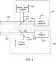
- the paired visible light and visible light second harmonic generation (SHG) cameras 160 include a visible light SHG camera 230 and a visible light camera 240 which are positioned to each receive light beam 165 via a beam splitter 250.
- beam splitter 250 is positioned to split light beam 165 into a first portion 235 that is provided to visible light SHG camera 230 and a second portion 245 that is provided to visible light camera 240.
- the paired IR and IR second harmonic generation (SHG) cameras 170 include an IR SHG camera 200 and an IR camera 210 which are positioned to each receive light beam 175 via a beam splitter 220.
- beam splitter 220 is positioned to split light beam 175 into a first portion 205 that is provided to IR SHG camera 200 and a second portion 215 that is provided to IR camera 210.
- Each of the cameras/detectors 140, 150, 190. 200, 210, 230 and 240 produces an output signal that is communicated in a conventional manner to a processor 180 in FIG. 1 via a link 181 for processing as discussed below.
- the reflected light beams 145, 155, 165, 175, and 195 are at a particular angle with respect to the surface of an article (sometimes referred to herein as a "device") under test 105 based on the fixed angles that beams of coherent visible light 115, 125 and 135 are directed at the surface of the article ("device") under test 105.
- the cameras/detectors 140, 150, 190. 200, 210, 230 and 240 are thus positioned to receive such light beams.
- Each camera 140, 150, 200, 210, 230, 240 is a conventional detector as defined below with respect to FIG. 4 .
- light sources 110, 120, 130 and cameras/detectors 140, 150, 190, 200, 210, 230 and 240 are fixed in place and the surface of the article under test 105 may be moved so that the area 190 of the beams of coherent visible light 115, 125, 135 moves over the entire surface of article under test 105.
- light sources 110, 120, 130 and cameras 140, 150, 190, 200, 210, 230 and 240 are mounted on a fixture that moves along the surface of article under test 105.
- light sources 110, 120, 130 are arranged to raster the respective output beams of coherent visible light 115, 125, 135 across the surface of the article under test 105, and the cameras/detectors 140, 150, 190, 200, 210, 230 and 240 arranged to move proportionally to receive the respective associated return light beams 145, 155, 165, 175, 195.
- each of the light sources 120, 130 is configured similarly, as shown by representative light source 300, but each is configured for a different intensity, frequency and/or polarization.
- Light source 110 is a broadband IR light source that does not require any frequency control but may include intensity and frequency controls similar to that of representative light source 300.
- Light source 300 includes a light emitter 310, an intensity control 320, a frequency control 330 and a polarization control 340 for outputting a light beam 350.
- Light emitter 310 is preferably a narrow frequency bandwidth visible pulse laser and, may be, for example a pulsed diode laser, a continuous wave diode laser or a pulsed solid state laser or a continuous wave solid state laser.
- Intensity controls may include broadband filters for reducing intensity or may specifically refer to certain frequency notch filters which are intended to drop intensity levels where the cameras/detectors can act in a linear fashion.
- Frequency controls can be accomplished in simple cases by frequency dependent color filters or notch filters and in more elaborate by a spectrophotometer that is typically composed of a diffraction grating which operates at a frequency or bandwidth of interest.
- the key point for the frequency control is to ensure that only light in beam 350 is directed at the surface of the article under test 105 and that stray light produced by light emitter 310 is removed, and as one of ordinary skill in the art will readily recognize, other frequency selective elements may also be used.
- Polarization control typically consists of two separate optical elements, a polarizer which only passes light of one polarization and a polarization modifying element - typically a halfway plate or a quarter wave plate.
- a halfway plate is used to rotate the polarization to the desired orientation.
- a quarter wave plate is used to change the polarization from linear to circular or from circular to linear as needed.
- the polarizer is the last element before light beam 350 leaves the source and heads for the surface of the article under testl05.
- Each light source 110, 120, 130 is configured, based on the selection of light emitter 310, intensity control 320, frequency control 330 and polarization control 340 in each to provide a respective beam of coherent visible light 115, 125, 135.
- Detector 185 is a broadband IR camera or a spectrometer and does not require any frequency control but includes intensity and frequency controls similar to that of representative camera 400.
- Camera 400 includes a capture element 410, a polarization control 420, a frequency control 430 and an intensity control 440 for receiving light beam 450.
- Exemplary capture elements 34 include, without limitation, cameras, CCD devices, imaging arrays, photometers, and like devices.
- the frequency control 430 and intensity control 440 operate on light beam 450 in a similar manner as intensity control 320 and frequency control 330 operate on light beam 350 as discussed above.
- polarization control 420 consists of a half wave plate and quarter wave combination, followed by a polarizer.
- the system 100 shown in FIG. 1 provides a combination of linear infrared spectroscopy, second order surface frequency mixing spectroscopy, and third-order nonlinear optics (e.g., Raman spectroscopy) spectroscopy.
- a broadband IR light source and corresponding broadband IR light detector allows processor 180 to generate a spectrally sensitive signal.
- Processor 180 analyzes this spectrally sensitive signal to identify peaks thereon.
- a signal based on a broad IR input will naturally have some IR frequencies that are resonant with materials present at the surface or interface of the article under test 105. The presence of a resonance leads to enhanced nonlinear interaction, which results in such "peaks" in the output spectrum.
- Processor 180 is configured to interrogate the output spectrum of the spectrally sensitive signal in order to determine the presence of any peaks.
- System 100 provides a number of ways of performing species identification and allows the cross correlation between the three types of spectroscopies in order to avoid false negative spectral features.
- visible light source 120 and broadband IR light source 110 are configured and positioned to provide light signals which allow the processor 180 to generate simultaneous linear (same frequency) and non-linear (second harmonic generation) real time spectroscopic signals, in conjunction with paired visible light and visible light second harmonic generation (SHG) cameras 160 and paired IR and IR SHG cameras 170.
- paired visible light and visible light second harmonic generation (SHG) cameras 160 and paired IR and IR SHG cameras 170 are positioned at a particular predetermined angle to receive the appropriate respective return light beams 165, 175 from surface of the article under test 105.
- visible light source 120 and broadband IR light source 110 are also configured and positioned to provide light signals which allow the processor 180 to generate a sum-frequency ( ⁇ IR + ⁇ VISIBLE ) real-time spectroscopic signal, in conjunction with sum-frequency camera 150.
- sum-frequency camera 150 is positioned at a particular predetermined angle to receive the appropriate return light beams 155 from the surface of the article under test 105.
- visible light source 120 and visible light source 130 are configured and positioned to provide light signals which allow the processor 180 to generate a third-order (2 ⁇ VIS1 - ⁇ VIS2 ) (e.g., Raman) real-time spectroscopic signal, in conjunction with Raman (third-order) camera 140.
- Raman (third-order) camera 140 is positioned at a particular predetermined angle to receive the appropriate return light beam 145 from the surface of the article under test 105.
- the processor 180 is coupled to receive signals from each of cameras/detectors 140, 150, 190, 200, 210, 230 and 240 and is configured to calculate in real time a linear spectroscopic signal, a second harmonic generation spectroscopic signal, a sum-frequency spectroscopic signal and a third-order spectroscopic signal, and a spectrally sensitive signal.
- the processor 180 is also configured to compare each calculated signal with each other calculated signal and with a predetermined baseline signal to ensure that the article under test conforms to an expected value.
- Processor 180 also processes the spectrally sensitive signal in order to identify any peaks therein. Such peaks can indicate [Jeff could we explain a bit what the peaks are used for].
- processor 180 determines that the calculated signals indicate that the article under test does not conform to the expected value, processor 180 provides a fault signal which is used to halt formation of the part under test 105 for either repair thereof or so that part under test 105 may be immediately discarded.
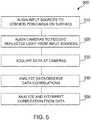
- step 510 the input light sources are aligned to a common point or area on the surface of the article under test.
- step 520 the cameras are aligned to receive light reflected from the input sources.
- the third-order camera 140, the sum-frequency camera 150, the visible light and visible light SHG cameras 160, the IR and IR SHG cameras 170, and the broadband IR light detector 185 are aligned separately.
- step 530 data is acquired at each of the cameras/detectors.
- step 540 the acquired data is analyzed, and correlations among the data are observed.
- step 550 the correlations among the data are interpreted to ensure that the article under test conforms to an expected value.
- the active-real time characterization system 100 of the present disclosure may be applied to testing for composition of the article under test, for identifying contamination on the surface of the article under test or for a combination of both material composition and contamination identification.
- the active real-time characterization system 100 of the present disclosure may be used to test graphite fiber-based materials, polymer/plastic materials, glass fiber reinforcement-based materials such as fiberglass and glass laminate aluminum reinforced epoxy (“GLARE”), resins, plastics or polymers without reinforcement fibers, metals, and ceramics including glass materials.
- GLARE glass laminate aluminum reinforced epoxy
- the present system provides the ability to more accurately monitor the chemistry of composite parts during formation by avoiding false negative spectral features.
- This system can allow, in some cases, defects to be repaired and thus prevent the loss of the composite part. In other cases, this system can ensure that production is halted as soon as a defect is identified, and thus preventing further costly work from being performed on a composite part destined to be discarded.
- the data generated by the active-real time characterization system 100 of the present disclosure is combined for analysis with data separately generated by way of UV-VIS-NIR spectroscopy, IR spectroscopy, microwave spectroscopy, THz spectroscopy, ultrasonic NDE/NDI, Raman spectroscopy, Brillouin spectroscopy and/or ellipsometry.
Landscapes
- Physics & Mathematics (AREA)
- Health & Medical Sciences (AREA)
- Life Sciences & Earth Sciences (AREA)
- Chemical & Material Sciences (AREA)
- Immunology (AREA)
- General Health & Medical Sciences (AREA)
- General Physics & Mathematics (AREA)
- Analytical Chemistry (AREA)
- Pathology (AREA)
- Biochemistry (AREA)
- Spectroscopy & Molecular Physics (AREA)
- Nuclear Medicine, Radiotherapy & Molecular Imaging (AREA)
- Nonlinear Science (AREA)
- Optics & Photonics (AREA)
- Engineering & Computer Science (AREA)
- Food Science & Technology (AREA)
- Medicinal Chemistry (AREA)
- Investigating Or Analysing Materials By Optical Means (AREA)
- Investigating Materials By The Use Of Optical Means Adapted For Particular Applications (AREA)
Abstract
Description
- This disclosure relates generally to an active real-time characterization system that provides spectrally broadband characterization.
- In recent years, aircraft manufacturers have developed aircraft designs and aircraft fabrication methods that make greater use of carbon fiber composite materials and the like ("composite materials" or "CFCM"), such as graphite/epoxy, carbon fiber reinforced plastic ("CFRP") and graphite reinforced polymer ("GRP"). Composite materials are significantly lighter than traditional aircraft materials (e.g. aluminum, titanium, steel and alloys thereof), and can provide high strength with low weight, allowing lighter, more fuel efficient aircraft. In some newer aircraft, for example, the majority of the primary structure, including the fuselage and wing, is made of composite materials. One drawback in the growing use of carbon fiber composite materials is the lack of effective non-destructive evaluation type testing methodologies available for testing such materials during and after manufacture. In particular, there is a lack of non-destructive evaluation type testing systems for providing real time characterization of composites during overlay manufacturing.
- Accordingly, there is a need for a testing system which addresses the drawbacks identified above.
- In a first aspect, a system for providing active real-time characterization of an article under test. The system includes a broadband infrared light source for outputting a beam of broadband infrared light. The infrared light source is configured to direct the beam of broadband infrared light at a particular area on the article under test. A broadband IR light detector is configured to receive a first predetermined return beam of light from the particular area on the article under test. A processor is coupled to receive signals from the broadband IR light detector. The processor is configured to calculate in real time a spectrally sensitive signal, the processor configured to analyze the calculated spectrally sensitive signal to ensure that the article under test conforms to an expected value.
- In a further example, a first visible light source outputs a first beam of coherent visible light. The first visible light source is configured to direct the first beam of coherent visible light at the same particular area on the article under test. A visible light camera and a visible light second harmonic generation camera are each be configured to receive a second predetermined return beam of light from the particular area on the article under test. An infrared camera and an infrared second harmonic generation camera are each configured to receive a third predetermined return beam of light from the particular area on the article under test. The processor is coupled to receive signals from the visible light camera, the visible light second harmonic generation camera, the infrared camera and the infrared second harmonic generation camera. The processor is configured to calculate in real time a linear spectroscopic signal and a second harmonic generation spectroscopic signal. The processor is configured to compare each calculated signal with each other calculated signal and with a predetermined baseline signal to ensure that the article under test conforms to an expected value.
- In a still further example, the system includes a second visible light source for outputting a second beam of coherent visible light. The second visible light source is configured to direct the second beam of coherent visible light at the same particular area on the article under test. A sum-frequency camera is configured to receive a fourth return beam of light from the particular area on the article under test. A third-order camera is configured to receive a fifth return beam of light from the particular area on the article under test. The processor is "coupled to receive signals from the sum-frequency camera and the third-order camera. The processor is configured to calculate in real time a sum-frequency spectroscopic signal and a third-order spectroscopic signal and to compare the sum-frequency spectroscopic signal and the third-order spectroscopic signal with the other calculated signals and with a predetermined baseline signal to ensure that the article under test conforms to an expected value.
- Still further, each of the sources includes an intensity control for setting a predetermined intensity for the respective output beam of light and/or a polarization control for setting a predetermined polarization for the respective output beam of light. Similarly, each of the cameras includes an intensity control for setting a predetermined intensity for the respective input beam of light and/or a polarization control for setting a predetermined polarization for the respective input beam of light. In addition, a beam splitter is configured to split a return beam of light into two portions, a first portion directed to the visible light camera and a second portion directed to the visible light second harmonic generation camera. Finally, the broadband IR light detector may be a broadband IR camera or a spectrometer.
- In a second aspect, a system for providing active real-time characterization of an article under test. The system includes a broadband infrared light source for outputting a beam of broadband infrared light, the infrared light source configured to direct the beam of broadband infrared light at a particular area on the article under test. A first visible light source outputs a first beam of coherent visible light. The first visible light source is configured to direct the first beam of coherent visible light at the same particular area on the article under test. A second visible light source outputs a second beam of coherent visible light. The second visible light source is configured to direct the second beam of coherent visible light at the same particular area on the article under test. A broadband IR light detector is configured to receive a first predetermined return beam of light from the particular area on the article under test. A third-order camera is configured to receive a third return beam of light from the particular area on the article under test. A processor is coupled to receive signals from the broadband IR light detector, and the third-order camera. The processor is configured to calculate in real time a spectrally sensitive signal and a third-order spectroscopic signal. The processor is configured to analyze the calculated spectrally sensitive signal to ensure that the article under test conforms to an expected value and to compare each calculated signal with each other calculated signal and with a predetermined baseline signal to ensure that the article under test conforms to an expected value.
- In a further example, a visible light camera and a visible light second harmonic generation camera are each configured to receive a second predetermined return beam of light from the particular area on the article under test. An infrared camera and an infrared second harmonic generation camera are each configured to receive a third predetermined return beam of light from the particular area on the article under test. The processor is coupled to receive signals from the visible light camera, the visible light second harmonic generation camera, the infrared camera, and the infrared second harmonic generation camera. The processor is configured to calculate in real time a linear spectroscopic signal and a second harmonic generation spectroscopic signal and to compare the linear spectroscopic signal and the second harmonic generation spectroscopic signal with the other calculated signals and with a predetermined baseline signal to ensure that the article under test conforms to an expected value.
- In a still further example, a sum-frequency camera is configured to receive a fourth return beam of light from the particular area on the article under test. The processor is coupled to receive signals from the sum-frequency camera. The processor is configured to calculate in real time a sum-frequency signal and to compare the sum-frequency signal with the other calculated signals and with a predetermined baseline signal to ensure that the article under test conforms to an expected value.
- In a third aspect, a method for active real-time characterization of an article under test. A broadband infrared light source is directed at an area on a surface of the article under test. A broadband IR light detector is aligned to receive light from the broadband infrared light source reflected from the surface of the article under test. Data is acquired from the broadband IR light detector based on the received light. The data from the broadband IR light detector is analyzed and correlations among the data are observed. Finally, the correlations among the data are analyzed and interpreted to ensure that the article under test conforms to an expected value.
- In a further example, a first visible light source and a second visible light source is directed at the area on a surface of the article under test. A visible light camera and a visible light second harmonic generation camera are aligned to receive light from the broadband infrared light source, the first visible light source, and the second visible light source reflected from the surface of the article under test. Data is acquired from the visible light camera and the visible light second harmonic generation camera. The data from the visible light camera and the visible light second harmonic generation camera is analyzed and correlations among the data from the broadband IR light detector, the visible light camera and the visible light second harmonic generation camera are observed. The correlations among the data is analyzed and interpreted to ensure that the article under test conforms to an expected value.
- The features, functions, and advantages that have been discussed can be achieved independently in various examples or may be combined in yet other examples, further details of which can be seen with reference to the following description and drawings.
- The following detailed description, given by way of example and not intended to limit the present disclosure solely thereto, will best be understood in conjunction with the accompanying drawings in which:
-
FIG. 1 is a block diagram of an active real-time characterization system for use during composite overlay manufacturing according to an aspect of the present disclosure; -
FIG. 2 is a block diagram showing the composition of the infrared light and visible light camera systems according to an aspect of the present disclosure; -
FIG. 3 is a block diagram showing the composition of the light sources according to an aspect of the present disclosure; -
FIG. 4 is a block diagram showing the composition of the cameras according to an aspect of the present disclosure; and -
FIG. 5 is a flow chart of a method for operating the active real-time characterization system of the present disclosure. - In the present disclosure, like reference numbers refer to like elements throughout the drawings, which illustrate various exemplary examples of the present disclosure.
- Referring now to
FIG. 1 , the active real-time characterization system 100 of the present disclosure includes a broadband infrared (IR)light source 110, a first visiblelight source 120 and a second visiblelight source 130. The use of broadbandIR light source 110 allowssystem 100 to provide spectral sensitivity. Each of thelight sources area 190 on a surface of an article undertest 105, e.g., a part constructed from carbon-fiber composites. In particular,broadband IR source 110 is positioned to direct a beam oflight 115 atarea 190, first visiblelight source 120 is positioned to direct a coherent beam oflight 125 atarea 190, and send visiblelight source 130 is positioned to direct a beam of coherentvisible light 135 atarea 190. The beams of coherentvisible light light sources light sources visible light light source area 190. Broadband IRlight source 110 is configured to output light at a broad spectrum of IR wavelength (i.e., a spectrum of IR radiation frequencies that excite or interact with multiple IR resonances or material responses at the same time), while first visiblelight source 120 is configured to output light at a first fixed, predetermined visible wavelength and second visiblelight source 130 is configured to output light at a second fixed, predetermined visible wavelength, different from the first fixed, predetermined visible wavelength. -
System 100 inFIG. 1 also includes a number of cameras or detectors for detecting light reflected from the surface of an article undertest 105, including a Raman (third-order)camera 140 which receives alight beam 145 and a sum-frequency camera 150 which receives alight beam 155.System 100 also includes paired visible and visible second harmonic generation (SHG)cameras 160 which receive alight beam 165, and paired IR andIR SHG cameras 170 which receive alight beam 175. Finally,system 100 includes a broadbandIR light detector 185 which receives alight beam 195.Detector 185 may be a broadband IR camera or a spectrometer, for example. Referring now toFIG. 2 , the paired visible light and visible light second harmonic generation (SHG)cameras 160 include a visiblelight SHG camera 230 and a visiblelight camera 240 which are positioned to each receivelight beam 165 via abeam splitter 250. In particular,beam splitter 250 is positioned to splitlight beam 165 into afirst portion 235 that is provided to visiblelight SHG camera 230 and asecond portion 245 that is provided to visiblelight camera 240. Similarly, the paired IR and IR second harmonic generation (SHG)cameras 170 include anIR SHG camera 200 and anIR camera 210 which are positioned to each receivelight beam 175 via abeam splitter 220. In particular,beam splitter 220 is positioned to splitlight beam 175 into afirst portion 205 that is provided toIR SHG camera 200 and asecond portion 215 that is provided toIR camera 210. Each of the cameras/detectors processor 180 inFIG. 1 via alink 181 for processing as discussed below. As also discussed below, the reflectedlight beams test 105 based on the fixed angles that beams of coherentvisible light test 105. The cameras/detectors camera FIG. 4 . - As one of ordinary skill in the art will readily recognize,
light sources detectors test 105 may be moved so that thearea 190 of the beams of coherentvisible light test 105. In another example,light sources cameras test 105. In yet another example,light sources visible light test 105, and the cameras/detectors - Referring now to
FIG. 3 , each of thelight sources light source 300, but each is configured for a different intensity, frequency and/or polarization.Light source 110 is a broadband IR light source that does not require any frequency control but may include intensity and frequency controls similar to that of representativelight source 300.Light source 300 includes alight emitter 310, anintensity control 320, afrequency control 330 and apolarization control 340 for outputting alight beam 350.Light emitter 310 is preferably a narrow frequency bandwidth visible pulse laser and, may be, for example a pulsed diode laser, a continuous wave diode laser or a pulsed solid state laser or a continuous wave solid state laser. Intensity controls may include broadband filters for reducing intensity or may specifically refer to certain frequency notch filters which are intended to drop intensity levels where the cameras/detectors can act in a linear fashion. Frequency controls can be accomplished in simple cases by frequency dependent color filters or notch filters and in more elaborate by a spectrophotometer that is typically composed of a diffraction grating which operates at a frequency or bandwidth of interest. The key point for the frequency control is to ensure that only light inbeam 350 is directed at the surface of the article undertest 105 and that stray light produced bylight emitter 310 is removed, and as one of ordinary skill in the art will readily recognize, other frequency selective elements may also be used. Polarization control typically consists of two separate optical elements, a polarizer which only passes light of one polarization and a polarization modifying element - typically a halfway plate or a quarter wave plate. A halfway plate is used to rotate the polarization to the desired orientation. A quarter wave plate is used to change the polarization from linear to circular or from circular to linear as needed. As shown, the polarizer is the last element beforelight beam 350 leaves the source and heads for the surface of the article under testl05. Eachlight source light emitter 310,intensity control 320,frequency control 330 andpolarization control 340 in each to provide a respective beam of coherentvisible light - Referring now to
FIG. 4 , each of thecameras representative camera 400.Detector 185 is a broadband IR camera or a spectrometer and does not require any frequency control but includes intensity and frequency controls similar to that ofrepresentative camera 400.Camera 400 includes acapture element 410, apolarization control 420, afrequency control 430 and anintensity control 440 for receivinglight beam 450. Exemplary capture elements 34 include, without limitation, cameras, CCD devices, imaging arrays, photometers, and like devices. Thefrequency control 430 andintensity control 440 operate onlight beam 450 in a similar manner asintensity control 320 andfrequency control 330 operate onlight beam 350 as discussed above. Preferably,polarization control 420 consists of a half wave plate and quarter wave combination, followed by a polarizer. - In operation, the
system 100 shown inFIG. 1 provides a combination of linear infrared spectroscopy, second order surface frequency mixing spectroscopy, and third-order nonlinear optics (e.g., Raman spectroscopy) spectroscopy. In addition, the use of a broadband IR light source and corresponding broadband IR light detector allowsprocessor 180 to generate a spectrally sensitive signal.Processor 180 analyzes this spectrally sensitive signal to identify peaks thereon. A signal based on a broad IR input will naturally have some IR frequencies that are resonant with materials present at the surface or interface of the article undertest 105. The presence of a resonance leads to enhanced nonlinear interaction, which results in such "peaks" in the output spectrum.Processor 180 is configured to interrogate the output spectrum of the spectrally sensitive signal in order to determine the presence of any peaks.System 100 provides a number of ways of performing species identification and allows the cross correlation between the three types of spectroscopies in order to avoid false negative spectral features. - In particular, visible
light source 120 and broadbandIR light source 110 are configured and positioned to provide light signals which allow theprocessor 180 to generate simultaneous linear (same frequency) and non-linear (second harmonic generation) real time spectroscopic signals, in conjunction with paired visible light and visible light second harmonic generation (SHG)cameras 160 and paired IR andIR SHG cameras 170. As one of ordinary skill in the art will readily recognize, paired visible light and visible light second harmonic generation (SHG)cameras 160 and paired IR andIR SHG cameras 170 are positioned at a particular predetermined angle to receive the appropriate respective return light beams 165, 175 from surface of the article undertest 105. - Further, visible
light source 120 and broadbandIR light source 110 are also configured and positioned to provide light signals which allow theprocessor 180 to generate a sum-frequency (ωIR + ωVISIBLE) real-time spectroscopic signal, in conjunction with sum-frequency camera 150. As one of ordinary skill in the art will readily recognize, sum-frequency camera 150 is positioned at a particular predetermined angle to receive the appropriate returnlight beams 155 from the surface of the article undertest 105. - Finally, visible
light source 120 and visiblelight source 130 are configured and positioned to provide light signals which allow theprocessor 180 to generate a third-order (2ωVIS1 - ωVIS2) (e.g., Raman) real-time spectroscopic signal, in conjunction with Raman (third-order)camera 140. As one of ordinary skill in the art will readily recognize, Raman (third-order)camera 140 is positioned at a particular predetermined angle to receive the appropriate returnlight beam 145 from the surface of the article undertest 105. - The
processor 180 is coupled to receive signals from each of cameras/detectors processor 180 is also configured to compare each calculated signal with each other calculated signal and with a predetermined baseline signal to ensure that the article under test conforms to an expected value.Processor 180 also processes the spectrally sensitive signal in order to identify any peaks therein. Such peaks can indicate [Jeff could we explain a bit what the peaks are used for]. When theprocessor 180 determines that the calculated signals indicate that the article under test does not conform to the expected value,processor 180 provides a fault signal which is used to halt formation of the part undertest 105 for either repair thereof or so that part undertest 105 may be immediately discarded. - Referring now to
FIG. 5 , aflow chart 500 of a method for operating the active real-time characterization system of the present disclosure is shown. Instep 510, the input light sources are aligned to a common point or area on the surface of the article under test. Next, atstep 520, the cameras are aligned to receive light reflected from the input sources. As evident from the discussion above, the third-order camera 140, the sum-frequency camera 150, the visible light and visiblelight SHG cameras 160, the IR andIR SHG cameras 170, and the broadbandIR light detector 185 are aligned separately. Further, atstep 530, data is acquired at each of the cameras/detectors. After this, atstep 540, the acquired data is analyzed, and correlations among the data are observed. Finally, atstep 550, the correlations among the data are interpreted to ensure that the article under test conforms to an expected value. - As one of ordinary skill in the art will readily recognize, the active-real
time characterization system 100 of the present disclosure may be applied to testing for composition of the article under test, for identifying contamination on the surface of the article under test or for a combination of both material composition and contamination identification. In addition, the active real-time characterization system 100 of the present disclosure may be used to test graphite fiber-based materials, polymer/plastic materials, glass fiber reinforcement-based materials such as fiberglass and glass laminate aluminum reinforced epoxy ("GLARE"), resins, plastics or polymers without reinforcement fibers, metals, and ceramics including glass materials. - By providing a combination of linear, non-linear, sum-frequency and third-order real time spectroscopic signals, the present system provides the ability to more accurately monitor the chemistry of composite parts during formation by avoiding false negative spectral features. This system can allow, in some cases, defects to be repaired and thus prevent the loss of the composite part. In other cases, this system can ensure that production is halted as soon as a defect is identified, and thus preventing further costly work from being performed on a composite part destined to be discarded.
- In further examples, the data generated by the active-real
time characterization system 100 of the present disclosure is combined for analysis with data separately generated by way of UV-VIS-NIR spectroscopy, IR spectroscopy, microwave spectroscopy, THz spectroscopy, ultrasonic NDE/NDI, Raman spectroscopy, Brillouin spectroscopy and/or ellipsometry. - Further, the disclosure comprises examples according to the following clauses:
-
Clause 1. A system for providing active real-time characterization of an article under test, comprising:- a broadband infrared light source for outputting a beam of broadband infrared light, the infrared light source configured to direct the beam of broadband infrared light at a particular area on the article under test;
- a broadband IR light detector configured to receive a first predetermined return beam of light from the particular area on the article under test; and
- a processor coupled to receive signals from the broadband IR light detector, the processor configured to calculate in real time a spectrally sensitive signal, the processor configured to analyze the calculated spectrally sensitive signal to ensure that the article under test conforms to an expected value.
-
Clause 2. The system ofClause 1, further comprising:- a first visible light source for outputting a first beam of coherent visible light, the first visible light source configured to direct the first beam of coherent visible light at the same particular area on the article under test;
- a visible light camera and a visible light second harmonic generation camera, the visible light camera and visible light second harmonic generation camera each configured to receive a second predetermined return beam of light from the particular area on the article under test;
- an infrared camera and an infrared second harmonic generation camera, the infrared camera and infrared second harmonic generation camera each configured to receive a third predetermined return beam of light from the particular area on the article under test; and
- wherein the processor is coupled to receive signals from the visible light camera, the visible light second harmonic generation camera, the infrared camera and the infrared second harmonic generation camera, and is configured to calculate in real time a linear spectroscopic signal and a second harmonic generation spectroscopic signal, the processor configured to compare each calculated signal with each other calculated signal and with a predetermined baseline signal to ensure that the article under test conforms to an expected value.
- Clause 3. The system of
Clause 2, further comprising:- a second visible light source for outputting a second beam of coherent visible light, the second visible light source configured to direct the second beam of coherent visible light at the same particular area on the article under test;
- a sum-frequency camera configured to receive a fourth return beam of light from the particular area on the article under test;
- a third-order camera configured to receive a fifth return beam of light from the particular area on the article under test; and
- wherein the processor is coupled to receive signals from the sum-frequency camera and the third-order camera, and the processor is configured to calculate in real time a sum-frequency spectroscopic signal and a third-order spectroscopic signal and to compare the sum-frequency spectroscopic signal and the third-order spectroscopic signal with the other calculated signals and with a predetermined baseline signal to ensure that the article under test conforms to an expected value.
- Clause 4. The system of any preceding Clause, wherein each of the sources includes an intensity control for setting a predetermined intensity for the respective output beam of light.
- Clause 5. The system of any preceding Clause, wherein each of the sources includes a polarization control for setting a predetermined polarization for the respective output beam of light.
- Clause 6. The system of any preceding Clause, wherein each of the cameras includes an intensity control for setting a predetermined intensity for the respective input beam of light.
- Clause 7. The system of any preceding Clause, wherein each of the cameras includes a polarization control for setting a predetermined polarization for the respective input beam of light.
- Clause 8. The system of any preceding Clause, further comprising a beam splitter configured to split a return beam of light into two portions, a first portion directed to the visible light camera and a second portion directed to the visible light second harmonic generation camera.
- Clause 9. The system of any preceding Clause, wherein the broadband IR light detector is a broadband IR camera or a spectrometer.
- Clause 10. A system for providing active real-time characterization of an article under test, comprising:
- a broadband infrared light source for outputting a beam of broadband infrared light, the infrared light source configured to direct the beam of broadband infrared light at a particular area on the article under test;
- a first visible light source for outputting a first beam of coherent visible light, the first visible light source configured to direct the first beam of coherent visible light at the same particular area on the article under test;
- a second visible light source for outputting a second beam of coherent visible light, the second visible light source configured to direct the second beam of coherent visible light at the same particular area on the article under test;
- a broadband IR light detector configured to receive a first predetermined return beam of light from the particular area on the article under test;
- a third-order camera configured to receive a third return beam of light from the particular area on the article under test; and
- a processor coupled to receive signals from the broadband IR light detector, and the third-order camera, the processor configured to calculate in real time a spectrally sensitive signal and a third-order spectroscopic signal, the processor configured to analyze the calculated spectrally sensitive signal to ensure that the article under test conforms to an expected value and to compare each calculated signal with each other calculated signal and with a predetermined baseline signal to ensure that the article under test conforms to an expected value.
- Clause 11. The system of Clause 10, further comprising:
- a visible light camera and a visible light second harmonic generation camera, the visible light camera and visible light second harmonic generation camera each configured to receive a second predetermined return beam of light from the particular area on the article under test;
- an infrared camera and an infrared second harmonic generation camera, the infrared camera and infrared second harmonic generation camera each configured to receive a third predetermined return beam of light from the particular area on the article under test; and
- wherein the processor is coupled to receive signals from the visible light camera, the visible light second harmonic generation camera, the infrared camera, and the infrared second harmonic generation camera, the processor configured to calculate in real time a linear spectroscopic signal and a second harmonic generation spectroscopic signal and to compare the linear spectroscopic signal and the second harmonic generation spectroscopic signal with the other calculated signals and with a predetermined baseline signal to ensure that the article under test conforms to an expected value.
- Clause 12. The system of Clause 11, further comprising:
- a sum-frequency camera configured to receive a fourth return beam of light from the particular area on the article under test; and
- wherein the processor is coupled to receive signals from the sum-frequency camera, the processor configured to calculate in real time a sum-frequency signal and to compare the sum-frequency signal with the other calculated signals and with a predetermined baseline signal to ensure that the article under test conforms to an expected value.
- Clause 13. The system of any of Clauses 10 to 12, wherein each of the sources includes an intensity control for setting a predetermined intensity for the respective output beam of light.
- Clause 14. The system of any of Clauses 10 to 13, wherein each of the sources includes a polarization control for setting a predetermined polarization for the respective output beam of light.
- Clause 15. The system of any of Clauses 10 to 14, wherein each of the cameras includes an intensity control for setting a predetermined intensity for the respective input beam of light.
- Clause 16. The system of any of Clauses 10 to 15, wherein each of the cameras includes a polarization control for setting a predetermined polarization for the respective input beam of light.
- Clause 17. The system of any of Clauses 10 to 16, further comprising a beam splitter configured to split a return beam of light into two portions, a first portion directed to the visible light camera and a second portion directed to the visible light second harmonic generation camera.
- Clause 18. The system of any of Clauses 10 to 17, wherein the broadband IR light detector is a broadband IR camera or a spectrometer.
- Clause 19. A method for active real-time characterization of an article under test, comprising the steps of:
- directing a broadband infrared light source at an area on a surface of the article under test;
- aligning a broadband IR light detector to receive light from the broadband infrared light source reflected from the surface of the article under test;
- acquiring data from the broadband IR light detector based on the received light;
- analyzing the data from the broadband IR light detector and observing correlations among the data; and
- analyzing and interpreting the correlations among the data to ensure that the article under test conforms to an expected value.
- Clause 20. The method of claim 19, further comprising the steps of:
- directing a first visible light source and a second visible light source at the area on a surface of the article under test;
- aligning a visible light camera and a visible light second harmonic generation camera to receive light from the broadband infrared light source, the first visible light source, and the second visible light source reflected from the surface of the article under test;
- acquiring data from the visible light camera and the visible light second harmonic generation camera;
- using the data from in the comparing and contrasting steps and analyzing and interpreting steps.
- analyzing the data from the visible light camera and the visible light second harmonic generation camera and observing correlations among the data from the broadband IR light detector, the visible light camera and the visible light second harmonic generation camera; and analyzing and interpreting the correlations among the data to ensure that the article under test conforms to an expected value.
- Although the present disclosure has been particularly shown and described with reference to the preferred examples and various aspects thereof, it will be appreciated by those of ordinary skill in the art that various changes and modifications may be made without departing from the spirit and scope of the disclosure. It is intended that the appended claims be interpreted as including the examples described herein, the alternatives mentioned above, and all equivalents thereto.
Claims (11)
- A system for providing active real-time characterization of an article under test, comprising:a broadband infrared light source (110) for outputting a beam of broadband infrared light (115), the infrared light source configured to direct the beam of broadband infrared light at a particular area (190) on the article under test;a broadband IR light detector (185) configured to receive a first predetermined return beam of light (195) from the particular area on the article under test; anda processor (180) coupled to receive signals from the broadband IR light detector, the processor configured to calculate in real time a spectrally sensitive signal, the processor configured to analyze the calculated spectrally sensitive signal to ensure that the article under test conforms to an expected value.
- The system of claim 1, further comprising:a first visible light source (120) for outputting a first beam of coherent visible light (125), the first visible light source configured to direct the first beam of coherent visible light at the same particular area on the article under test;a visible light camera (240) and a visible light second harmonic generation camera (230), the visible light camera and visible light second harmonic generation camera each configured to receive a second predetermined return beam of light (165(from the particular area on the article under test;an infrared camera (210) and an infrared second harmonic generation camera (200), the infrared camera and infrared second harmonic generation camera each configured to receive a third predetermined return beam of light (175) from the particular area on the article under test; andwherein the processor is coupled to receive signals from the visible light camera, the visible light second harmonic generation camera, the infrared camera and the infrared second harmonic generation camera, and is configured to calculate in real time a linear spectroscopic signal and a second harmonic generation spectroscopic signal, the processor configured to compare each calculated signal with each other calculated signal and with a predetermined baseline signal to ensure that the article under test conforms to an expected value.
- The system of claim 2, further comprising:a second visible light source (130) for outputting a second beam of coherent visible light (135), the second visible light source configured to direct the second beam of coherent visible light at the same particular area on the article under test;a sum-frequency camera (150) configured to receive a fourth return beam of light (155) from the particular area on the article under test;a third-order camera (140) configured to receive a fifth return beam of light (145) from the particular area on the article under test; andwherein the processor is coupled to receive signals from the sum-frequency camera and the third-order camera, and the processor is configured to calculate in real time a sum-frequency spectroscopic signal and a third-order spectroscopic signal and to compare the sum-frequency spectroscopic signal and the third-order spectroscopic signal with the other calculated signals and with a predetermined baseline signal to ensure that the article under test conforms to an expected value.
- The system of any of claims 1-3, wherein each of the sources includes an intensity control (320) for setting a predetermined intensity for the respective output beam of light.
- The system of any of claims 1-4, wherein each of the sources includes a polarization control (340) for setting a predetermined polarization for the respective output beam of light.
- The system of any of claims 2-5, wherein each of the cameras includes an intensity control (440) for setting a predetermined intensity for the respective input beam of light.
- The system of any of claims 2-6, wherein each of the cameras includes a polarization control (420) for setting a predetermined polarization for the respective input beam of light.
- The system of any of claims 2-7, further comprising a beam splitter (250) configured to split a return beam of light into two portions, a first portion directed to the visible light camera and a second portion directed to the visible light second harmonic generation camera.
- The system of any of claims 1-8, wherein the broadband IR light detector is a broadband IR camera or a spectrometer.
- A method for active real-time characterization of an article under test, comprising the steps of:directing a broadband infrared light source (110) at an area (190) on a surface of the article under test;aligning a broadband IR light detector (185) to receive light from the broadband infrared light source reflected from the surface of the article under test;acquiring data from the broadband IR light detector based on the received light;analyzing the data from the broadband IR light detector and observing correlations among the data; andanalyzing and interpreting the correlations among the data to ensure that the article under test conforms to an expected value.
- The method of claim 10, further comprising the steps of:directing a first visible light source (120) and a second visible light source (130) at the area on a surface of the article under test;aligning a visible light camera (240) and a visible light second harmonic generation camera (230) to receive light from the broadband infrared light source, the first visible light source, and the second visible light source reflected from the surface of the article under test;acquiring data from the visible light camera and the visible light second harmonic generation camera;using the data from in the comparing and contrasting steps and analyzing and interpreting steps.analyzing the data from the visible light camera and the visible light second harmonic generation camera and observing correlations among the data from the broadband IR light detector, the visible light camera and the visible light second harmonic generation camera; andanalyzing and interpreting the correlations among the data to ensure that the article under test conforms to an expected value.
Applications Claiming Priority (1)
| Application Number | Priority Date | Filing Date | Title |
|---|---|---|---|
| US15/902,201 US10712265B2 (en) | 2018-02-22 | 2018-02-22 | Active real-time characterization system providing spectrally broadband characterization |
Publications (1)
| Publication Number | Publication Date |
|---|---|
| EP3531109A1 true EP3531109A1 (en) | 2019-08-28 |
Family
ID=65496729
Family Applications (1)
| Application Number | Title | Priority Date | Filing Date |
|---|---|---|---|
| EP19157847.5A Pending EP3531109A1 (en) | 2018-02-22 | 2019-02-18 | Active real-time characterization system providing spectrally broadband characterization |
Country Status (2)
| Country | Link |
|---|---|
| US (1) | US10712265B2 (en) |
| EP (1) | EP3531109A1 (en) |
Families Citing this family (1)
| Publication number | Priority date | Publication date | Assignee | Title |
|---|---|---|---|---|
| CN114755689A (en) * | 2022-03-22 | 2022-07-15 | 南开大学 | Infrared measurement method, infrared measurement device, computer equipment and storage medium |
Citations (4)
| Publication number | Priority date | Publication date | Assignee | Title |
|---|---|---|---|---|
| US20150041654A1 (en) * | 2013-08-08 | 2015-02-12 | Stichting SRON - Netherlands Institute for Space Research | Method and system for inspection of composite assemblies using terahertz radiation |
| EP2977747A1 (en) * | 2014-07-23 | 2016-01-27 | Airbus Operations Limited | Method and apparatus for testing materials |
| US9404854B2 (en) * | 2014-10-22 | 2016-08-02 | The Boeing Company | Second and third order simultaneously non-linear optical processes and measurements for surface analysis |
| US20180013964A1 (en) * | 2014-10-28 | 2018-01-11 | The Boeing Company | Active real-time characterization system |
Family Cites Families (24)
| Publication number | Priority date | Publication date | Assignee | Title |
|---|---|---|---|---|
| US5973778A (en) | 1994-02-22 | 1999-10-26 | Boeing North American, Inc. | Method of monitoring a thin film of polyimide material using surface spectroscopy |
| US5841546A (en) * | 1996-03-01 | 1998-11-24 | Foster-Miller, Inc. | Non-contact spectroscopy system and process |
| CA2252552C (en) * | 1996-04-22 | 2003-04-22 | Autospect, Inc. | Method and system for inspecting a low gloss surface of an object at a vision station |
| US5793042A (en) * | 1996-09-30 | 1998-08-11 | Quick; Nathaniel R. | Infrared spectrophotometer accelerated corrosion-erosion analysis system |
| DE19816004A1 (en) * | 1998-04-09 | 1999-10-14 | Daimler Chrysler Ag | Arrangement for road condition detection |
| US6795175B2 (en) | 2002-05-21 | 2004-09-21 | The Boeing Company | System and method for imaging contamination on a surface |
| US6788405B2 (en) | 2002-06-12 | 2004-09-07 | The Boeing Company | Nonlinear optical system for sensing the presence of contamination on a semiconductor wafer |
| US6882414B2 (en) * | 2002-06-19 | 2005-04-19 | The Boeing Company | Broadband infrared spectral surface spectroscopy |
| US6781686B2 (en) | 2002-06-19 | 2004-08-24 | The Boeing Company | Femtosecond optical surface imaging |
| US7304305B2 (en) | 2002-06-19 | 2007-12-04 | The Boeing Company | Difference-frequency surface spectroscopy |
| US6819844B2 (en) | 2002-06-20 | 2004-11-16 | The Boeing Company | Fiber-optic based surface spectroscopy |
| US6798502B2 (en) | 2002-06-20 | 2004-09-28 | The Boeing Company | Microwave regime surface spectroscopy |
| US7514268B2 (en) * | 2003-11-24 | 2009-04-07 | The Boeing Company | Method for identifying contaminants |
| US7289656B2 (en) | 2003-12-02 | 2007-10-30 | The Boeing Company | Systems and methods for determining inconsistency characteristics of a composite structure |
| US7397598B2 (en) | 2004-08-20 | 2008-07-08 | Nikon Corporation | Light source unit and light irradiation unit |
| US7757558B2 (en) | 2007-03-19 | 2010-07-20 | The Boeing Company | Method and apparatus for inspecting a workpiece with angularly offset ultrasonic signals |
| FR2959305B1 (en) | 2010-04-26 | 2014-09-05 | Nanotec Solution | OPTICAL DEVICE AND METHOD FOR INSPECTING STRUCTURED OBJECTS. |
| TW201208220A (en) | 2010-06-17 | 2012-02-16 | Nikon Corp | Ultraviolet laser device |
| US8664583B2 (en) | 2011-07-01 | 2014-03-04 | The Boeing Company | Nonlinear optical surface sensing with a single thermo-electric detector |
| US9170172B2 (en) | 2011-08-23 | 2015-10-27 | The Boeing Company | Composite structure having an embedded sensing system |
| US20130050685A1 (en) | 2011-08-23 | 2013-02-28 | The Boeing Company | Composite structure having an embedded sensing system |
| US8789837B2 (en) | 2012-09-18 | 2014-07-29 | The Boeing Company | Transport and assembly system and method for composite barrel segments |
| JP2014178249A (en) * | 2013-03-15 | 2014-09-25 | Sumitomo Electric Ind Ltd | Film manufacturing method, film manufacturing process monitoring device and film inspection method |
| US20150148632A1 (en) * | 2013-11-26 | 2015-05-28 | David Alan Benaron | Calorie Monitoring Sensor And Method For Cell Phones, Smart Watches, Occupancy Sensors, And Wearables |
-
2018
- 2018-02-22 US US15/902,201 patent/US10712265B2/en active Active
-
2019
- 2019-02-18 EP EP19157847.5A patent/EP3531109A1/en active Pending
Patent Citations (4)
| Publication number | Priority date | Publication date | Assignee | Title |
|---|---|---|---|---|
| US20150041654A1 (en) * | 2013-08-08 | 2015-02-12 | Stichting SRON - Netherlands Institute for Space Research | Method and system for inspection of composite assemblies using terahertz radiation |
| EP2977747A1 (en) * | 2014-07-23 | 2016-01-27 | Airbus Operations Limited | Method and apparatus for testing materials |
| US9404854B2 (en) * | 2014-10-22 | 2016-08-02 | The Boeing Company | Second and third order simultaneously non-linear optical processes and measurements for surface analysis |
| US20180013964A1 (en) * | 2014-10-28 | 2018-01-11 | The Boeing Company | Active real-time characterization system |
Also Published As
| Publication number | Publication date |
|---|---|
| US20190257748A1 (en) | 2019-08-22 |
| US10712265B2 (en) | 2020-07-14 |
Similar Documents
| Publication | Publication Date | Title |
|---|---|---|
| US10200635B2 (en) | Active real-time characterization system | |
| US9404854B2 (en) | Second and third order simultaneously non-linear optical processes and measurements for surface analysis | |
| US10424056B2 (en) | Active real-time characterization system for monitoring absorption and curing rates of chemical substances | |
| US9632020B2 (en) | Non-linear optical ellipsometry for surface monitoring and characterization | |
| GB2360842A (en) | Investigating a sample using electromagnetic radiation | |
| EP3125019B1 (en) | Imaging system with controllable linear polarisation | |
| US10613026B2 (en) | Far-infrared imaging device and far-infrared imaging method | |
| US9329123B2 (en) | Multiplexed spectroscopic absorbance from CRDS wave forms | |
| JP2015526741A (en) | Long-wavelength infrared detection and image processing using a long-wavelength infrared light source | |
| CN114235700B (en) | Multi-component gas concentration detection device and method | |
| US20210341283A1 (en) | Device and method for measuring thickness and refractive index of multilayer thin film by using angle-resolved spectral reflectometry | |
| US10424057B2 (en) | Active real-time characterization system for detecting physical imperfections during semiconductor manufacturing | |
| US9557263B2 (en) | Terahertz material evaluation and characterization via material difference frequency generation | |
| CN109115682A (en) | A kind of spectrometer and its detection method for taking into account liquid and solid content detection | |
| US10712265B2 (en) | Active real-time characterization system providing spectrally broadband characterization | |
| US9557267B2 (en) | Terahertz imaging via simultaneous surface and sub-surface evaluation via non-linear optical response | |
| US10430936B2 (en) | Active real-time characterization system for identifying surface contamination | |
| US12163893B2 (en) | Sample ingredient analysis apparatus and sample ingredient analysis method using the same | |
| US10438337B2 (en) | Active real-time characterization system utilizing beam scanning for surface imaging | |
| US10578562B2 (en) | Active real-time characterization system using radio-frequency radiation | |
| US20220244169A1 (en) | Reflectometer, spectrophotometer, ellipsometer and polarimeter systems including a wavelength modifier | |
| JPH0459457U (en) | ||
| JPH11237285A (en) | Optical pulse diagnostic device | |
| Lee et al. | Optimization of the mode matching in pulsed cavity ringdown spectroscopy | |
| HK1199101B (en) | Raman spectrum system and method for measuring raman spectrum |
Legal Events
| Date | Code | Title | Description |
|---|---|---|---|
| PUAI | Public reference made under article 153(3) epc to a published international application that has entered the european phase |
Free format text: ORIGINAL CODE: 0009012 |
|
| STAA | Information on the status of an ep patent application or granted ep patent |
Free format text: STATUS: REQUEST FOR EXAMINATION WAS MADE |
|
| 17P | Request for examination filed |
Effective date: 20190218 |
|
| AK | Designated contracting states |
Kind code of ref document: A1 Designated state(s): AL AT BE BG CH CY CZ DE DK EE ES FI FR GB GR HR HU IE IS IT LI LT LU LV MC MK MT NL NO PL PT RO RS SE SI SK SM TR |
|
| AX | Request for extension of the european patent |
Extension state: BA ME |
|
| STAA | Information on the status of an ep patent application or granted ep patent |
Free format text: STATUS: EXAMINATION IS IN PROGRESS |
|
| 17Q | First examination report despatched |
Effective date: 20211213 |
|
| RAP3 | Party data changed (applicant data changed or rights of an application transferred) |
Owner name: THE BOEING COMPANY |
|
| GRAP | Despatch of communication of intention to grant a patent |
Free format text: ORIGINAL CODE: EPIDOSNIGR1 |
|
| STAA | Information on the status of an ep patent application or granted ep patent |
Free format text: STATUS: GRANT OF PATENT IS INTENDED |
|
| INTG | Intention to grant announced |
Effective date: 20260216 |
|
| RIN1 | Information on inventor provided before grant (corrected) |
Inventor name: HUNT, JEFFREY H. |