EP3531058B1 - Heat exchanger assembly - Google Patents
Heat exchanger assembly Download PDFInfo
- Publication number
- EP3531058B1 EP3531058B1 EP19158877.1A EP19158877A EP3531058B1 EP 3531058 B1 EP3531058 B1 EP 3531058B1 EP 19158877 A EP19158877 A EP 19158877A EP 3531058 B1 EP3531058 B1 EP 3531058B1
- Authority
- EP
- European Patent Office
- Prior art keywords
- core
- flow passages
- heat exchanger
- inlet manifold
- manifold
- Prior art date
- Legal status (The legal status is an assumption and is not a legal conclusion. Google has not performed a legal analysis and makes no representation as to the accuracy of the status listed.)
- Active
Links
Images


Classifications
-
- F—MECHANICAL ENGINEERING; LIGHTING; HEATING; WEAPONS; BLASTING
- F28—HEAT EXCHANGE IN GENERAL
- F28F—DETAILS OF HEAT-EXCHANGE AND HEAT-TRANSFER APPARATUS, OF GENERAL APPLICATION
- F28F7/00—Elements not covered by group F28F1/00, F28F3/00 or F28F5/00
- F28F7/02—Blocks traversed by passages for heat-exchange media
-
- F—MECHANICAL ENGINEERING; LIGHTING; HEATING; WEAPONS; BLASTING
- F28—HEAT EXCHANGE IN GENERAL
- F28D—HEAT-EXCHANGE APPARATUS, NOT PROVIDED FOR IN ANOTHER SUBCLASS, IN WHICH THE HEAT-EXCHANGE MEDIA DO NOT COME INTO DIRECT CONTACT
- F28D7/00—Heat-exchange apparatus having stationary tubular conduit assemblies for both heat-exchange media, the media being in contact with different sides of a conduit wall
- F28D7/0008—Heat-exchange apparatus having stationary tubular conduit assemblies for both heat-exchange media, the media being in contact with different sides of a conduit wall the conduits for one medium being in heat conductive contact with the conduits for the other medium
-
- F—MECHANICAL ENGINEERING; LIGHTING; HEATING; WEAPONS; BLASTING
- F02—COMBUSTION ENGINES; HOT-GAS OR COMBUSTION-PRODUCT ENGINE PLANTS
- F02C—GAS-TURBINE PLANTS; AIR INTAKES FOR JET-PROPULSION PLANTS; CONTROLLING FUEL SUPPLY IN AIR-BREATHING JET-PROPULSION PLANTS
- F02C7/00—Features, components parts, details or accessories, not provided for in, or of interest apart form groups F02C1/00 - F02C6/00; Air intakes for jet-propulsion plants
- F02C7/12—Cooling of plants
- F02C7/14—Cooling of plants of fluids in the plant, e.g. lubricant or fuel
-
- F—MECHANICAL ENGINEERING; LIGHTING; HEATING; WEAPONS; BLASTING
- F28—HEAT EXCHANGE IN GENERAL
- F28D—HEAT-EXCHANGE APPARATUS, NOT PROVIDED FOR IN ANOTHER SUBCLASS, IN WHICH THE HEAT-EXCHANGE MEDIA DO NOT COME INTO DIRECT CONTACT
- F28D21/00—Heat-exchange apparatus not covered by any of the groups F28D1/00 - F28D20/00
-
- F—MECHANICAL ENGINEERING; LIGHTING; HEATING; WEAPONS; BLASTING
- F28—HEAT EXCHANGE IN GENERAL
- F28D—HEAT-EXCHANGE APPARATUS, NOT PROVIDED FOR IN ANOTHER SUBCLASS, IN WHICH THE HEAT-EXCHANGE MEDIA DO NOT COME INTO DIRECT CONTACT
- F28D7/00—Heat-exchange apparatus having stationary tubular conduit assemblies for both heat-exchange media, the media being in contact with different sides of a conduit wall
- F28D7/16—Heat-exchange apparatus having stationary tubular conduit assemblies for both heat-exchange media, the media being in contact with different sides of a conduit wall the conduits being arranged in parallel spaced relation
-
- F—MECHANICAL ENGINEERING; LIGHTING; HEATING; WEAPONS; BLASTING
- F28—HEAT EXCHANGE IN GENERAL
- F28F—DETAILS OF HEAT-EXCHANGE AND HEAT-TRANSFER APPARATUS, OF GENERAL APPLICATION
- F28F21/00—Constructions of heat-exchange apparatus characterised by the selection of particular materials
- F28F21/08—Constructions of heat-exchange apparatus characterised by the selection of particular materials of metal
- F28F21/081—Heat exchange elements made from metals or metal alloys
- F28F21/084—Heat exchange elements made from metals or metal alloys from aluminium or aluminium alloys
-
- F—MECHANICAL ENGINEERING; LIGHTING; HEATING; WEAPONS; BLASTING
- F28—HEAT EXCHANGE IN GENERAL
- F28F—DETAILS OF HEAT-EXCHANGE AND HEAT-TRANSFER APPARATUS, OF GENERAL APPLICATION
- F28F21/00—Constructions of heat-exchange apparatus characterised by the selection of particular materials
- F28F21/08—Constructions of heat-exchange apparatus characterised by the selection of particular materials of metal
- F28F21/081—Heat exchange elements made from metals or metal alloys
- F28F21/087—Heat exchange elements made from metals or metal alloys from nickel or nickel alloys
-
- F—MECHANICAL ENGINEERING; LIGHTING; HEATING; WEAPONS; BLASTING
- F28—HEAT EXCHANGE IN GENERAL
- F28F—DETAILS OF HEAT-EXCHANGE AND HEAT-TRANSFER APPARATUS, OF GENERAL APPLICATION
- F28F9/00—Casings; Header boxes; Auxiliary supports for elements; Auxiliary members within casings
- F28F9/02—Header boxes; End plates
-
- F—MECHANICAL ENGINEERING; LIGHTING; HEATING; WEAPONS; BLASTING
- F28—HEAT EXCHANGE IN GENERAL
- F28F—DETAILS OF HEAT-EXCHANGE AND HEAT-TRANSFER APPARATUS, OF GENERAL APPLICATION
- F28F9/00—Casings; Header boxes; Auxiliary supports for elements; Auxiliary members within casings
- F28F9/02—Header boxes; End plates
- F28F9/0236—Header boxes; End plates floating elements
- F28F9/0239—Header boxes; End plates floating elements floating header boxes
-
- F—MECHANICAL ENGINEERING; LIGHTING; HEATING; WEAPONS; BLASTING
- F05—INDEXING SCHEMES RELATING TO ENGINES OR PUMPS IN VARIOUS SUBCLASSES OF CLASSES F01-F04
- F05D—INDEXING SCHEME FOR ASPECTS RELATING TO NON-POSITIVE-DISPLACEMENT MACHINES OR ENGINES, GAS-TURBINES OR JET-PROPULSION PLANTS
- F05D2230/00—Manufacture
- F05D2230/30—Manufacture with deposition of material
-
- F—MECHANICAL ENGINEERING; LIGHTING; HEATING; WEAPONS; BLASTING
- F28—HEAT EXCHANGE IN GENERAL
- F28D—HEAT-EXCHANGE APPARATUS, NOT PROVIDED FOR IN ANOTHER SUBCLASS, IN WHICH THE HEAT-EXCHANGE MEDIA DO NOT COME INTO DIRECT CONTACT
- F28D21/00—Heat-exchange apparatus not covered by any of the groups F28D1/00 - F28D20/00
- F28D2021/0019—Other heat exchangers for particular applications; Heat exchange systems not otherwise provided for
- F28D2021/0021—Other heat exchangers for particular applications; Heat exchange systems not otherwise provided for for aircrafts or cosmonautics
-
- F—MECHANICAL ENGINEERING; LIGHTING; HEATING; WEAPONS; BLASTING
- F28—HEAT EXCHANGE IN GENERAL
- F28D—HEAT-EXCHANGE APPARATUS, NOT PROVIDED FOR IN ANOTHER SUBCLASS, IN WHICH THE HEAT-EXCHANGE MEDIA DO NOT COME INTO DIRECT CONTACT
- F28D21/00—Heat-exchange apparatus not covered by any of the groups F28D1/00 - F28D20/00
- F28D2021/0019—Other heat exchangers for particular applications; Heat exchange systems not otherwise provided for
- F28D2021/008—Other heat exchangers for particular applications; Heat exchange systems not otherwise provided for for vehicles
- F28D2021/0091—Radiators
- F28D2021/0094—Radiators for recooling the engine coolant
-
- F—MECHANICAL ENGINEERING; LIGHTING; HEATING; WEAPONS; BLASTING
- F28—HEAT EXCHANGE IN GENERAL
- F28F—DETAILS OF HEAT-EXCHANGE AND HEAT-TRANSFER APPARATUS, OF GENERAL APPLICATION
- F28F9/00—Casings; Header boxes; Auxiliary supports for elements; Auxiliary members within casings
- F28F9/02—Header boxes; End plates
- F28F2009/0285—Other particular headers or end plates
- F28F2009/029—Other particular headers or end plates with increasing or decreasing cross-section, e.g. having conical shape
-
- F—MECHANICAL ENGINEERING; LIGHTING; HEATING; WEAPONS; BLASTING
- F28—HEAT EXCHANGE IN GENERAL
- F28F—DETAILS OF HEAT-EXCHANGE AND HEAT-TRANSFER APPARATUS, OF GENERAL APPLICATION
- F28F2255/00—Heat exchanger elements made of materials having special features or resulting from particular manufacturing processes
- F28F2255/02—Flexible elements
-
- F—MECHANICAL ENGINEERING; LIGHTING; HEATING; WEAPONS; BLASTING
- F28—HEAT EXCHANGE IN GENERAL
- F28F—DETAILS OF HEAT-EXCHANGE AND HEAT-TRANSFER APPARATUS, OF GENERAL APPLICATION
- F28F2265/00—Safety or protection arrangements; Arrangements for preventing malfunction
- F28F2265/26—Safety or protection arrangements; Arrangements for preventing malfunction for allowing differential expansion between elements
Definitions
- Heat exchangers provide a way to transfer heat away from such engines.
- Oil can be used to dissipate heat from engine components, such as engine bearings, electrical generators, and the like. Heat is typically transferred from the oil with heat exchangers to maintain oil temperatures at a desired range from approximately 37.8°C to 148.9°C (100° F to 300° F). In many instances, an external environment can be as low as -53.9 °C (-65°F) or the temperature of the aircraft fuel can be significantly lower than the oil temperatures. In such an example, a flow of cool air or the engine fuel can be used to cool the oil via the heat exchanger. For example, bleed air having a high temperature (>371 °C (>700 °F)) and pressure can be cooled with ambient external bypass air. Other applications utilize air, fuel, and oil to both cool and heat one another, depending on the need.
- heat exchangers can be placed in the aircraft for dissipating heat generated by electrical systems, such as within an avionics chassis.
- the heat exchangers can include a plurality of elements, such as conduits, to draw heat from the electrical components.
- the heat exchanger can be used to dissipate the heat drawn from the electrical components.
- JP S58 129 196 A discloses a backup spring fitted between a seal ring and the bottom of a groove for the seal ring so as to thrust the seal ring constantly against the inner wall of a tubular section of the vessel.
- EP 190 320 7 A1 discloses a heat exchanger having a heat transducer streamed by exhaust gas, and a housing outer cover surrounding the heat transducer
- WO2015126483 discloses a heat exchanger, comprising a core having a first set of flow passages and a second set of flow passages orthogonal to the first set of flow passages; a tubular inlet manifold having a fluid inlet, with the fluid inlet in fluid communication with the first set of flow passages; and a second tubular inlet manifold in fluid communication with the second set of flow passages.
- aspects of the disclosure described herein are directed to a heat exchanger assembly.
- the present disclosure will be described with respect to a heat exchanger provided in the interior of an aircraft engine. It will be understood, however, that aspects of the disclosure described herein are not so limited and can have general applicability within any environment requiring or utilizing heat exchangers or convective heat transfer, such as within a turbine engine for the aircraft, but also including non-aircraft applications, such as other mobile applications and non-mobile industrial, commercial, and residential applications.
- forward or “upstream” refers to moving in a direction being relatively closer to an inlet or source of a flow of fluid or gas through a heat exchanger.
- aft or “downstream” refers to a direction being relatively closer to an outlet or end of a heat exchanger.
- set can refer to one or more of an element.
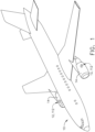
- an aircraft 10 includes a pair of heat exchangers 12, 112 (shown in dashed line), which are arranged in in a pair of aircraft engines 14 mounted to the aircraft 10.
- the heat exchangers 12, 112 aid in dissipating the heat generated by the engines 14.
- the heat exchangers 12, 112 can be located anywhere within the aircraft 10, not just within the engines 14 as illustrated.
- the heat exchangers 12, 112 can be used in any type of aircraft, for example, without limitation, fixed-wing, rotating-wing, rocket, commercial aircraft, personal aircraft, and military aircraft.
- aspects of the disclosure are not limited only to aircraft aspects, and can be included in other mobile and stationary configurations.
- Non-limiting example mobile configurations can include ground-based, water-based, or additional air-based vehicles.
- Any implementation has its own space constraints and temperature or operational requirements. As such, the design of the particular aspects of the heat exchanger as described herein can be tailored to suit specific installation requirements of the implementation.
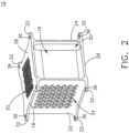
- the heat exchanger 12 can include a heat exchanger core 16 defining an inner section 20, and including a first side 22, a second side 24, a third side 26, and a fourth side 28.
- a first set of flow passages 30 extending from the first side 22 to the second side 24.
- a second set of flow passages 34 can extend from the third side 26 to the fourth side 28.
- the first set of flow passages 30 can be thermally coupled with the second set of flow passages 34 so that heat of a fluid, either gas or liquid, flowing through one can be transferred to a fluid flowing through the other.
- the first and second sets of flow passages 30, 34 can be intertwined and the first and second sets of flow passages 30, 34 can be complex, with a multi-faceted, convoluted geometry made from additive 3D metal printing, for example.
- the flow passages could be treacherous-path or diabolically convoluted geometries.
- other suitable methods of forming the core 16 having the first and second sets of flow passages 30, 34 are contemplated, such as casting in one non-limiting example.
- the heat exchanger core 16 can be considered as a monolithic block for the heat exchanger 12.
- the core 16 is preferably made of a material having a high heat transfer coefficient to facilitate transfer of heat between the first set of flow passages 30 and the second set of flow passages 34.
- a material having a high heat transfer coefficient can be aluminum, for example.
- nickel and cobalt alloys are possible alternatives.
- An outer housing or skin 18 can surround the core 16.
- a set of flanges 32 can extend from the skin 18, and can include apertures 36 provided in the flanges 32.
- one or more load paths can be included with the skin 18, adapted to receive physical or thermal loads during operation of the heat exchanger. Such load paths can be formed in the inner section 20, and can be dependent on the geometry of the core 16, or the first or second sets of flow passages 30, 34.
- the skin 18 can couple to and share such load paths. It is further contemplated that the skin 18 can include additional structures adapted to form a load path along or through the core 16 for carrying a structural or thermal load.
- the skin 18 can form the structural boundary for carrying the heat exchanger core 16, and can at least partially surround the core 16, or surround only a portion of the core 16. In one example, the skin 18 can be integral with the core 16.
- a set of manifolds 40 can couple to the core 16 or the skin 18 to provide for ingress and egress of fluid to the core 16.
- the core 16, the skin 18, and the manifolds 40, or any subset thereof, can be formed as an integral or unitary body, forming a single element having two or more of the core 16, skin 18, or the manifolds 40.
- Each manifold 40 can include an inlet plane 56 and an outlet plane 58, providing for ingress or egress of fluid to or from the manifold 40.
- the set of manifolds 40 can provide for ingress and egress of fluid to the first and second sets of flow passages 30, 34 via the inlet plane 56 or the outlet plane 58.
- the inlet plane 56 is spaced from the core 16, while the outlet plane 58 can be adjacent the core 16.
- the inlet plane 56 can be adjacent the core 16, while the outlet plane 58 can be spaced from the core 16.
- plane as used herein, in regards to an inlet plane 56 and an outlet plane 58, should not necessarily represent a geometrical plane or mean geometrically planar, but rather be representative of a boundary or threshold defining an inlet or an outlet for a referenced manifold 40, and can be relative to flow direction through the manifold 40.
- the set of manifolds 40 can include a first inlet manifold 42, a first outlet manifold 44, a second inlet manifold 46, and a second outlet manifold 48.
- a set of mounting flanges 62 can couple to the set of manifolds 40.
- the mounting flange 62 can mount to a fixed structure for mounting the heat exchanger 12, such as to a portion of the engine 14 of FIG. 1 .
- the first inlet manifold 42 couples to the rigid core 16 adjacent the first set of flow passages 30 at the first side 22.
- the first manifold 42 and the core 16 can be an integral body or a unitary body, formed as a single element incorporating both the manifold 42 and the core 16.
- a first inlet 60 can be formed in the first inlet manifold 42, spaced from the first set of flow passages 30.
- One or more sidewalls 64 can at least partially form the first inlet manifold 42 can extend between the mounting flange 62 and the core 16, defining an interior 66 for the first inlet manifold 42.
- a compliant portion 68 or compliant feature is provided at least partially along the sidewall 64 and forms at least a part of the sidewall 64.
- the compliant portion 68 can at least partially form the manifold 40 between the inlet plane 56 and the outlet plane 58.
- the compliant portion 68 has been illustrated as corrugations including a first compliant portion 68a in the sidewall 64.
- the first compliant portion 68a forms a portion of the first inlet manifold 42, and can be formed as an integral body with a remainder of the first inlet manifold 42.
- the first compliant portion 68a can include a plurality of ridges 78 that can be sized to a specific height, as may be desirable to tailor the compliant portion 68 and its movement to the particular inlet manifold.
- first compliant portion 68a can extend around the sidewall 64, such as when the sidewall 64 is cylindrical or conic, for example. In yet another example, it is contemplated that the entire length of the sidewall 64 is formed with the first compliant portion 68a or that the length of the sidewall 64 can include numerous compliant portions.
- the first compliant portion 68a can be rigid having a high tensile strength, while adapted to expand and contract during thermal expansion of the core 16.
- the first inlet manifold 42 can be made of nickel, nickel-cobalt, or a Nickel alloy, in non-limiting examples. Such materials provide for a high tensile strength, while the compliant portions 68 provide compliance under thermal expansion. Particularly, such materials can provide for increased strength and impact resistance up to 316 degrees Celsuis (C) (600 degrees Fahrenheit (F)), while more particularized alloys can provide for temperatures up to 538 degrees C (1000 degrees F) or more.
- the first outlet manifold 44 is fluidly coupled to the core 16 adjacent the first set of flow passages 30 at the second side 24.
- a first outlet 80 can be formed in the first outlet manifold 44, spaced from the first set of flow passages 30.
- the first outlet manifold 44 can be positioned opposite of the first inlet manifold 42, relative to the core 16, and can fluidly couple to the first inlet manifold 42 via the first set of flow passages 30.
- the first outlet manifold 44 can include a sidewall 82 and geometry similar to that of the first inlet manifold 42. While no compliant portion is shown on the first outlet manifold 44, it is contemplated that the first outlet manifold 44 can include one or more compliant portions, such as formed in the sidewall 82 or between the inlet plane 56 and the outlet plane 58.
- a second inlet manifold 46 couples to the core 16 adjacent the second set of flow passages 34 at the third side 26.
- a second inlet 70 can be formed in the second inlet manifold 46, and can be spaced from the second set of flow passages 34.
- a first sidewall 72 can extend from the core 16 to a second sidewalls 74.
- the second sidewall 74 can be arranged substantially orthogonal to the first sidewall 72; however, any orientation is contemplated.
- the first and second sidewalls 72, 74 can at least partially define an interior 76 for the second inlet manifold 46.
- Compliant portions 68 are included in both the first sidewall 72 and the second sidewall 74, and can at least partially form the second inlet manifold 46 between the inlet plane 56and the outlet plane 58.
- compliant portions have been illustrated as a second compliant portion 68b provided in the first sidewall 72 and a third compliant portion 68c provided in the second sidewall 74.
- the second compliant portion 68b and the third compliant portion 68c both form a portion of the second inlet manifold 46, and can form an integral body with a remainder of the second inlet manifold 46.
- the compliant portions 68 can permit flexion of the second inlet manifold 46 in two degrees of freedom, orthogonal to one another in the illustrated example.
- a sizing of the ridges 78 for the first compliant portion 68a can be larger than a sizing of the ridges 78 of the second compliant portion 68b.
- a sizing of the ridges 78 among all compliant portion 68a-68c can be varied to be tailored to an anticipated thermal expansion of the related manifold 40, and can be larger or smaller than one another as may be preferred.
- the second outlet manifold 48 can include a first sidewall 86 and a second sidewall 88, similar to the sidewalls 72, 74 of the second inlet manifold 44.
- the second outlet manifold 48 couples to the core 16 adjacent the second set of flow passages 34 at the fourth side 28.
- a second outlet 84 can be formed in the second outlet manifold 48, and can be spaced from the second set of flow passages 34.
- the second outlet manifold 48 can be positioned opposite of the second inlet manifold 46 relative to the core 16, and can fluidly couple to the second inlet manifold 46 via the second set of flow passages 34.
- the second outlet manifold 48 can include one or more compliant portion 68, such as within the sidewalls 86, 88, or between the inlet plane 56 and the outlet plane 58.
- the organization for the heat exchanger 12 and manifolds 40 as shown are exemplary, and that any suitable geometry for the core 16 that provides for a heat exchange between a hot fluid and a cold fluid can form the suitable heat exchanger 12.
- the manifolds 40 have been illustrated merely for exemplary purposes and can include any suitable shape, profile, arrangement, or attachments for effectively providing one or more fluids to, and removing one or more fluids from the heat exchanger 12 or the core 16.
- the compliant portion are illustrated and described as corrugated, it should be appreciated that any suitable flexural element adapted to flex relative to thermal expansion of the core 16 can be utilized.
- Alternative compliant portions can include corrugations, convolutions, sinusoidal convolutions, or sinusoids in non-limiting examples.
- the compliant portion 68 can be a compliant wall, having an extendable and retractable section. Such extendable and retractable sections can be formed as convolutions or corrugations, permitting extension or retraction of the manifold at the compliant portion. Similarly, any number of compliant portion 68 in any position along the manifolds is contemplated. Furthermore, it is contemplated that the compliant portion can be provided on the skin 18, as well as any structural portion of the core 16.
- a compliant portion 68 can be formed as a housing compliant portion 68d, formed within a portion of the outer housing or the skin 18. Such a compliant portion 68d can provide for reduction of local stresses along a load path of the housing 18 or skin 18.
- a first fluid can be provided through the core 16 along the first set of flow passages 30, such as a hot fluid. Therefore, the first inlet manifold 42, the first set of flow passages 30, and the first outlet manifold 44 can form a hot fluid path.
- the first inlet 60 can be a hot inlet and the first outlet 80 can be a hot outlet.
- a second fluid can be provided through the core 16 along the second set of flow passages 34, such as a cold fluid. Therefore, the second inlet manifold 46, the first set of flow passages 34, and the first outlet manifold 44 can form a cold fluid path.
- the second inlet 70 can be a cold inlet and the second outlet 84 can be a cold outlet.
- a heat exchange takes place within the core 16, cooling the hot fluid and heating the cold fluid.
- An average of the temperatures between the hot fluid and the cold fluid within the core 16 can define a mean temperature for fluids passing through the core 16.
- a large temperature difference, or temperature gradient can exist between the mean temperature of the rigid core 16 and the hot or cold fluids at the first and second inlet manifolds 42, 46, respectively.
- thermal expansion and contraction of the core 16 can occur.
- Such expansion and contraction of the core 16 can cause thermal stresses at the junction between the core 16 and the structurally fixed manifolds 40.
- the thermal stresses can be the result of the significant temperature change of the core 16 resulting in thermal expansion.
- An additional and superimposed high temperature gradient condition can occur between a local hot section of the thermal core adjacent to the cold inlet manifold fluid. A significant temperature gradient will exist at this location.
- a similar condition can occur at a local region between a cold fluid passage of the core and the hot inlet manifold fluid.
- Such thermal and superimposed structural stresses can result in fracture or deformation of the heat exchanger 12, which can reduce component life or require increased maintenance.
- thermal stresses can be exacerbated due to a structurally stiff core 16, resultant of the complex geometry of the first and second sets of flow passages 30, 34 forming the core 16.
- thermal expansion of the core 16 can cause physical stresses at the junction between the manifolds 40 and the mounting flanges 62.
- the structurally stiff mounting flange 62 can be particularly susceptible to damage or deformation due to the increased superimposed thermal and physical stresses.
- the compliant portions 68 provide for flexion of portions of the heat exchanger 12, where they have been included at the core 16 to the manifolds 40 during thermal expansion or contraction of the core 16. Flexion portions of the heat exchanger 12 at the compliant portions 68 provide for reducing local thermal and physical stresses, which can reduce the incidence of damage or deformation of the heat exchanger 12. Among other things, the compliant portions 68 can decouple the thermal stresses from the mounting flanges 62. Such decoupling of the thermal stresses reduces the stresses on the fixed mounts of the heat exchanger 12. Reduction of the stresses on the fixed mounts of the heat exchanger can provide for increased operational lifetime of the heat exchanger 12, and reduce required maintenance.
- FIG. 4 another exemplary heat exchanger not falling under the scope of the claims 112 that can be utilized in the aircraft 10 is illustrated and can be substantially similar to the heat exchanger 12 of FIG. 3 . As such, similar numerals will be used to described similar elements, increase by a value of one hundred and the discussion will be limited to differences between the heat exchanger 12 and the heat exchanger 112.
- a first inlet manifold 142 and a second inlet manifold 146 include a shared wall 152 extending between a boundary 154 and a core 116, and can at least partially form the first and second inlet manifolds 142, 146.
- the shared wall 152 can be a structurally stiff sidewall that at least partially defines both the first inlet manifold 142 and the second inlet manifold 146.
- the boundary 154 can be a fixed boundary, for example, or can be a floating boundary at the junction between the first and second inlet manifolds 142, 146.
- a compliant portion 168 or compliant feature can be provided in the shared wall 152, or can at least partially form the manifold 140 between an inlet plane 156 and an outlet plane 158.
- the compliant portion 168 has been illustrated as corrugations in the shared wall 152.
- Alternative compliant portions can include corrugations, convolutions, sinusoidal convolutions, or sinusoids in non-limiting examples.
- the compliant portion 168 can provide compliance for both the first inlet manifold 142 and the second inlet manifold 146 simultaneously relative to thermal expansion of the core 116, which can reduce cost and complexity of the design. Additionally, having the compliant portion 168 provided along a shared wall 152 can provide for improved compliance between the rigid core 116 and two inlet manifold walls.
- the large temperature gradients between the two incoming fluids is transferred away from the weaker core material locations and into the two manifolds with the higher tensile strength material (>689Mpa (>100 ksi) UTS).
- Such a shared compliant portion can provide for reducing local thermal stresses in the core 116 and transferring the combined thermal and structural stresses to the higher strength manifold material.
- a method 190 of forming a heat exchanger can includes: at 192, forming a complex, thermally optimized, rigid core with at least a first set of flow passages; and, at 194, electroforming a first manifold having at least a first wall onto the core.
- forming the core can include any core as described herein, such as the core 16 of FIG. 2 .
- Forming the core 16 can include a first set of flow passages, such as the first set of flow passages 30 of FIG. 2 .
- the core 16 could additionally form a second set of flow passages, such as the second set of flow passages 34 of FIG. 2 , or any suitable number of sets of flow passages.
- the first and second sets of flow passages 30, 34 can be intertwined among one another, and can form a monolithic body.
- Forming the core can include forming the core with direct metal laser melting (DMLM) or direct metal laser sintering (DMLS), or any other suitable method capable of forming the complex geometries of the core 16 and the first and second sets of flow passages 30, 34.
- DMLM direct metal laser melting
- DMLS direct metal laser sintering
- any suitable additive manufacturing process can be used to form the core 16.
- the core can be formed of a metal having a high heat transfer coefficient, such as aluminum.
- a first manifold such as any of the set of manifolds 40 or the first inlet manifold 42 described herein, can be electroformed onto a portion of the core 16.
- the manifold or manifolds can be high-strength compliant inlet and outlet manifolds, including a compliant portion provided on the first wall.
- the first inlet manifold 42 can define a first fluid inlet that is in fluid communication with the first set of flow passages 30.
- At least a portion of the first manifold can include a compliant portion, such as the compliant portions 68 of FIG. 2 .
- the manifold can be formed from a metal having a high temperature and tensile strength, such as nickel, nickel-cobalt, or a nickel alloy.
- a second manifold such as the second inlet manifold 46, or additional manifolds can be electroformed onto the core 16.
- One or more of the second inlet manifold 46 or additional manifolds can include another compliant portions or corrugated portion.
- the second inlet manifold 46 can include the compliant portion or corrugated portion.
- Such manifolds 46 can include one or more fluid inlets or outlets for the first set of flow passages 30 or the second set of flow passages 34.
- Typical heat exchangers have high local thermal stresses at the rigid thermal core, the hot inlet manifold, and the cold inlet manifold.
- the large temperature differences between the hot inlet and the cold inlets, the high structural stiffness of the core, and the rigid housing connections to adjacent fixed boundary conditions such as the mounting flanges results in high local thermal stresses.
- Utilizing a hybrid DMLM core with additively manufactured outer manifold walls including the compliant portion provides for reducing the high local thermal stresses.
- additive manufacturing, such as electroforming, to form the heat exchanger permits a complex geometry for the core, as well as the compliant structures of the manifold having a high tensile strength. Additionally, utilizing the compliant flexures permits the walls of the manifolds to be thinner, which can decrease weight, which can decrease specific fuel consumption in particular implementations.
Landscapes
- Engineering & Computer Science (AREA)
- Mechanical Engineering (AREA)
- General Engineering & Computer Science (AREA)
- Physics & Mathematics (AREA)
- Thermal Sciences (AREA)
- Chemical & Material Sciences (AREA)
- Combustion & Propulsion (AREA)
- Heat-Exchange Devices With Radiators And Conduit Assemblies (AREA)
Description
- Contemporary engines used in aircraft produce substantial amounts of heat that must be transferred away from the engine in one way or another. Heat exchangers provide a way to transfer heat away from such engines.
- Oil can be used to dissipate heat from engine components, such as engine bearings, electrical generators, and the like. Heat is typically transferred from the oil with heat exchangers to maintain oil temperatures at a desired range from approximately 37.8°C to 148.9°C (100° F to 300° F). In many instances, an external environment can be as low as -53.9 °C (-65°F) or the temperature of the aircraft fuel can be significantly lower than the oil temperatures. In such an example, a flow of cool air or the engine fuel can be used to cool the oil via the heat exchanger. For example, bleed air having a high temperature (>371 °C (>700 °F)) and pressure can be cooled with ambient external bypass air. Other applications utilize air, fuel, and oil to both cool and heat one another, depending on the need.
- Additionally, heat exchangers can be placed in the aircraft for dissipating heat generated by electrical systems, such as within an avionics chassis. The heat exchangers can include a plurality of elements, such as conduits, to draw heat from the electrical components. The heat exchanger can be used to dissipate the heat drawn from the electrical components.
-
JP S58 129 196 A EP 190 320 7 A1WO2015126483 discloses a heat exchanger, comprising a core having a first set of flow passages and a second set of flow passages orthogonal to the first set of flow passages; a tubular inlet manifold having a fluid inlet, with the fluid inlet in fluid communication with the first set of flow passages; and a second tubular inlet manifold in fluid communication with the second set of flow passages. - The invention is defined by the appended claims. In the following, any method and/or apparatus referred to as embodiments but nevertheless do not fall within the scope of the appended claims are to be understood as examples helpful in understanding the invention.
- In the drawings:
-
FIG. 1 is a perspective view of an aircraft having a heat exchanger provided in an aircraft engine, in accordance with various aspects described herein. -
FIG. 2 is a perspective view of a heat exchanger that can be used in the aircraft ofFIG. 1 . -
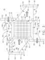
FIG. 3 is a schematic view of a heat exchanger according to the present claimed invention including a set of compliant electroformed features that can be used in the aircraft ofFIG. 1 . -
FIG. 4 is a schematic, cross-sectional view of a heat exchanger not falling under the scope of the claims assembly having a compliant electroformed feature that can be used in the aircraft ofFIG. 1 . -
FIG. 5 is a flow chart illustrating a method of forming a heat exchanger such as the heat exchanger ofFIG. 3 , in accordance with various aspects described herein. - Aspects of the disclosure described herein are directed to a heat exchanger assembly. For purposes of illustration, the present disclosure will be described with respect to a heat exchanger provided in the interior of an aircraft engine. It will be understood, however, that aspects of the disclosure described herein are not so limited and can have general applicability within any environment requiring or utilizing heat exchangers or convective heat transfer, such as within a turbine engine for the aircraft, but also including non-aircraft applications, such as other mobile applications and non-mobile industrial, commercial, and residential applications.
- As used herein, the term "forward" or "upstream" refers to moving in a direction being relatively closer to an inlet or source of a flow of fluid or gas through a heat exchanger. The term "aft" or "downstream" refers to a direction being relatively closer to an outlet or end of a heat exchanger. As used herein, the term "set" can refer to one or more of an element. All directional references (e.g., radial, axial, proximal, distal, upper, lower, upward, downward, left, right, lateral, front, back, top, bottom, above, below, vertical, horizontal, clockwise, counterclockwise, upstream, downstream, forward, aft, etc.) are only used for identification purposes to aid the reader's understanding of the present disclosure, and do not create limitations, particularly as to the position, orientation, or use of aspects of the disclosure described herein. Connection references (e.g., attached, coupled, connected, and joined) are to be construed broadly and can include intermediate members between a collection of elements and relative movement between elements unless otherwise indicated. The exemplary drawings are for purposes of illustration only and the dimensions, positions, order and relative sizes reflected in the drawings attached hereto can vary. As used herein, the term "set" or a set of an article should be understood to include any number of said article, including only one.
- Referring now to
FIG. 1 , anaircraft 10 includes a pair ofheat exchangers 12, 112 (shown in dashed line), which are arranged in in a pair ofaircraft engines 14 mounted to theaircraft 10. Theheat exchangers engines 14. It should be understood that theheat exchangers aircraft 10, not just within theengines 14 as illustrated. For example, there can be any number of heat exchangers arranged around theaircraft 10 at any position. While illustrated in a commercial airliner, theheat exchangers - Referring now to
FIG. 2 , theheat exchanger 12 can include aheat exchanger core 16 defining aninner section 20, and including afirst side 22, asecond side 24, athird side 26, and afourth side 28. A first set offlow passages 30 extending from thefirst side 22 to thesecond side 24. A second set offlow passages 34 can extend from thethird side 26 to thefourth side 28. The first set offlow passages 30 can be thermally coupled with the second set offlow passages 34 so that heat of a fluid, either gas or liquid, flowing through one can be transferred to a fluid flowing through the other. In one non-limiting example, the first and second sets offlow passages flow passages core 16 having the first and second sets offlow passages heat exchanger core 16 can be considered as a monolithic block for theheat exchanger 12. Thecore 16 is preferably made of a material having a high heat transfer coefficient to facilitate transfer of heat between the first set offlow passages 30 and the second set offlow passages 34. One such suitable material can be aluminum, for example. For high temperature applications, nickel and cobalt alloys are possible alternatives. - An outer housing or
skin 18 can surround thecore 16. A set offlanges 32 can extend from theskin 18, and can includeapertures 36 provided in theflanges 32. While not shown, one or more load paths can be included with theskin 18, adapted to receive physical or thermal loads during operation of the heat exchanger. Such load paths can be formed in theinner section 20, and can be dependent on the geometry of thecore 16, or the first or second sets offlow passages skin 18 can couple to and share such load paths. It is further contemplated that theskin 18 can include additional structures adapted to form a load path along or through thecore 16 for carrying a structural or thermal load. Thus, theskin 18 can form the structural boundary for carrying theheat exchanger core 16, and can at least partially surround thecore 16, or surround only a portion of thecore 16. In one example, theskin 18 can be integral with thecore 16. - Referring now to
FIG. 3 , a set ofmanifolds 40, shown as fourmanifolds 40, can couple to thecore 16 or theskin 18 to provide for ingress and egress of fluid to thecore 16. Thecore 16, theskin 18, and themanifolds 40, or any subset thereof, can be formed as an integral or unitary body, forming a single element having two or more of thecore 16,skin 18, or the manifolds 40.Eachmanifold 40 can include aninlet plane 56 and anoutlet plane 58, providing for ingress or egress of fluid to or from the manifold 40.The set ofmanifolds 40 can provide for ingress and egress of fluid to the first and second sets offlow passages inlet plane 56 or theoutlet plane 58. As such, for a manifold 40 having a flow entering the first and second sets offlow passages inlet plane 56 is spaced from thecore 16, while theoutlet plane 58 can be adjacent thecore 16. Similarly, but opposite, a manifold 40 providing for flow coming from the first and second sets offlow passages inlet plane 56 can be adjacent thecore 16, while theoutlet plane 58 can be spaced from thecore 16. It should be understood that "plane" as used herein, in regards to aninlet plane 56 and anoutlet plane 58, should not necessarily represent a geometrical plane or mean geometrically planar, but rather be representative of a boundary or threshold defining an inlet or an outlet for a referencedmanifold 40, and can be relative to flow direction through the manifold 40. It should be understood that any suitable geometry for the set ofmanifolds 40 is contemplated. The set ofmanifolds 40 can include afirst inlet manifold 42, afirst outlet manifold 44, asecond inlet manifold 46, and asecond outlet manifold 48. A set of mountingflanges 62 can couple to the set ofmanifolds 40. The mountingflange 62 can mount to a fixed structure for mounting theheat exchanger 12, such as to a portion of theengine 14 ofFIG. 1 . - The
first inlet manifold 42 couples to therigid core 16 adjacent the first set offlow passages 30 at thefirst side 22. Alternatively, thefirst manifold 42 and the core 16 can be an integral body or a unitary body, formed as a single element incorporating both the manifold 42 and thecore 16. Afirst inlet 60 can be formed in thefirst inlet manifold 42, spaced from the first set offlow passages 30. One or more sidewalls 64 can at least partially form thefirst inlet manifold 42 can extend between the mountingflange 62 and thecore 16, defining an interior 66 for thefirst inlet manifold 42. Acompliant portion 68 or compliant feature is provided at least partially along thesidewall 64 and forms at least a part of thesidewall 64. Alternatively, thecompliant portion 68 can at least partially form the manifold 40 between theinlet plane 56 and theoutlet plane 58. As a non-limiting example, thecompliant portion 68 has been illustrated as corrugations including a firstcompliant portion 68a in thesidewall 64. The firstcompliant portion 68a forms a portion of thefirst inlet manifold 42, and can be formed as an integral body with a remainder of thefirst inlet manifold 42. The firstcompliant portion 68a can include a plurality ofridges 78 that can be sized to a specific height, as may be desirable to tailor thecompliant portion 68 and its movement to the particular inlet manifold. It is contemplated that the firstcompliant portion 68a can extend around thesidewall 64, such as when thesidewall 64 is cylindrical or conic, for example. In yet another example, it is contemplated that the entire length of thesidewall 64 is formed with the firstcompliant portion 68a or that the length of thesidewall 64 can include numerous compliant portions. The firstcompliant portion 68a can be rigid having a high tensile strength, while adapted to expand and contract during thermal expansion of thecore 16. Thefirst inlet manifold 42 can be made of nickel, nickel-cobalt, or a Nickel alloy, in non-limiting examples. Such materials provide for a high tensile strength, while thecompliant portions 68 provide compliance under thermal expansion. Particularly, such materials can provide for increased strength and impact resistance up to 316 degrees Celsuis (C) (600 degrees Fahrenheit (F)), while more particularized alloys can provide for temperatures up to 538 degrees C (1000 degrees F) or more. - The
first outlet manifold 44 is fluidly coupled to the core 16 adjacent the first set offlow passages 30 at thesecond side 24. Afirst outlet 80 can be formed in thefirst outlet manifold 44, spaced from the first set offlow passages 30. Thefirst outlet manifold 44 can be positioned opposite of thefirst inlet manifold 42, relative to thecore 16, and can fluidly couple to thefirst inlet manifold 42 via the first set offlow passages 30. Thefirst outlet manifold 44 can include asidewall 82 and geometry similar to that of thefirst inlet manifold 42. While no compliant portion is shown on thefirst outlet manifold 44, it is contemplated that thefirst outlet manifold 44 can include one or more compliant portions, such as formed in thesidewall 82 or between theinlet plane 56 and theoutlet plane 58. - A
second inlet manifold 46 couples to the core 16 adjacent the second set offlow passages 34 at thethird side 26. Asecond inlet 70 can be formed in thesecond inlet manifold 46, and can be spaced from the second set offlow passages 34. Afirst sidewall 72 can extend from the core 16 to asecond sidewalls 74. Thesecond sidewall 74 can be arranged substantially orthogonal to thefirst sidewall 72; however, any orientation is contemplated. The first andsecond sidewalls second inlet manifold 46. -
Compliant portions 68 are included in both thefirst sidewall 72 and thesecond sidewall 74, and can at least partially form thesecond inlet manifold 46 between the inlet plane 56and theoutlet plane 58. By way of non-limiting examples such compliant portions have been illustrated as a secondcompliant portion 68b provided in thefirst sidewall 72 and a third compliant portion 68c provided in thesecond sidewall 74. The secondcompliant portion 68b and the third compliant portion 68c both form a portion of thesecond inlet manifold 46, and can form an integral body with a remainder of thesecond inlet manifold 46. Ascompliant portions 68 are provided in both thefirst sidewall 72 and thesecond sidewall 74, thecompliant portions 68 can permit flexion of thesecond inlet manifold 46 in two degrees of freedom, orthogonal to one another in the illustrated example. In one example, a sizing of theridges 78 for the firstcompliant portion 68a can be larger than a sizing of theridges 78 of the secondcompliant portion 68b. Alternatively, a sizing of theridges 78 among allcompliant portion 68a-68c can be varied to be tailored to an anticipated thermal expansion of the relatedmanifold 40, and can be larger or smaller than one another as may be preferred. - The
second outlet manifold 48 can include afirst sidewall 86 and asecond sidewall 88, similar to thesidewalls second inlet manifold 44. Thesecond outlet manifold 48 couples to the core 16 adjacent the second set offlow passages 34 at thefourth side 28. Asecond outlet 84 can be formed in thesecond outlet manifold 48, and can be spaced from the second set offlow passages 34. Thesecond outlet manifold 48 can be positioned opposite of thesecond inlet manifold 46 relative to thecore 16, and can fluidly couple to thesecond inlet manifold 46 via the second set offlow passages 34. It is further contemplated that thesecond outlet manifold 48 can include one or morecompliant portion 68, such as within thesidewalls inlet plane 56 and theoutlet plane 58. - It should be appreciated that the organization for the
heat exchanger 12 andmanifolds 40 as shown are exemplary, and that any suitable geometry for the core 16 that provides for a heat exchange between a hot fluid and a cold fluid can form thesuitable heat exchanger 12. It should be understood that themanifolds 40 have been illustrated merely for exemplary purposes and can include any suitable shape, profile, arrangement, or attachments for effectively providing one or more fluids to, and removing one or more fluids from theheat exchanger 12 or thecore 16. While the compliant portion are illustrated and described as corrugated, it should be appreciated that any suitable flexural element adapted to flex relative to thermal expansion of the core 16 can be utilized. Alternative compliant portions can include corrugations, convolutions, sinusoidal convolutions, or sinusoids in non-limiting examples. Alternatively, thecompliant portion 68 can be a compliant wall, having an extendable and retractable section. Such extendable and retractable sections can be formed as convolutions or corrugations, permitting extension or retraction of the manifold at the compliant portion. Similarly, any number ofcompliant portion 68 in any position along the manifolds is contemplated. Furthermore, it is contemplated that the compliant portion can be provided on theskin 18, as well as any structural portion of thecore 16. - In one alternative examples, a
compliant portion 68 can be formed as a housingcompliant portion 68d, formed within a portion of the outer housing or theskin 18. Such acompliant portion 68d can provide for reduction of local stresses along a load path of thehousing 18 orskin 18. - During operation, a first fluid can be provided through the
core 16 along the first set offlow passages 30, such as a hot fluid. Therefore, thefirst inlet manifold 42, the first set offlow passages 30, and thefirst outlet manifold 44 can form a hot fluid path. Thefirst inlet 60 can be a hot inlet and thefirst outlet 80 can be a hot outlet. - A second fluid can be provided through the
core 16 along the second set offlow passages 34, such as a cold fluid. Therefore, thesecond inlet manifold 46, the first set offlow passages 34, and thefirst outlet manifold 44 can form a cold fluid path. Thesecond inlet 70 can be a cold inlet and thesecond outlet 84 can be a cold outlet. - During simultaneous flow of the hot fluid and the cold fluid, a heat exchange takes place within the
core 16, cooling the hot fluid and heating the cold fluid. An average of the temperatures between the hot fluid and the cold fluid within thecore 16 can define a mean temperature for fluids passing through thecore 16. Dependent on the extreme temperatures of the hot and cold fluids a large temperature difference, or temperature gradient, can exist between the mean temperature of therigid core 16 and the hot or cold fluids at the first and second inlet manifolds 42, 46, respectively. Resultant of increasing or decreasing temperatures in thecore 16, thermal expansion and contraction of the core 16 can occur. Such expansion and contraction of the core 16 can cause thermal stresses at the junction between the core 16 and the structurally fixedmanifolds 40. The thermal stresses can be the result of the significant temperature change of the core 16 resulting in thermal expansion. An additional and superimposed high temperature gradient condition can occur between a local hot section of the thermal core adjacent to the cold inlet manifold fluid. A significant temperature gradient will exist at this location. A similar condition can occur at a local region between a cold fluid passage of the core and the hot inlet manifold fluid. Such thermal and superimposed structural stresses can result in fracture or deformation of theheat exchanger 12, which can reduce component life or require increased maintenance. Furthermore, such thermal stresses can be exacerbated due to a structurallystiff core 16, resultant of the complex geometry of the first and second sets offlow passages core 16. - Additionally, thermal expansion of the core 16 can cause physical stresses at the junction between the
manifolds 40 and the mountingflanges 62. As a result, the structurally stiff mountingflange 62 can be particularly susceptible to damage or deformation due to the increased superimposed thermal and physical stresses. - The
compliant portions 68 provide for flexion of portions of theheat exchanger 12, where they have been included at the core 16 to themanifolds 40 during thermal expansion or contraction of thecore 16. Flexion portions of theheat exchanger 12 at thecompliant portions 68 provide for reducing local thermal and physical stresses, which can reduce the incidence of damage or deformation of theheat exchanger 12. Among other things, thecompliant portions 68 can decouple the thermal stresses from the mountingflanges 62. Such decoupling of the thermal stresses reduces the stresses on the fixed mounts of theheat exchanger 12. Reduction of the stresses on the fixed mounts of the heat exchanger can provide for increased operational lifetime of theheat exchanger 12, and reduce required maintenance. - Referring now to
FIG. 4 , another exemplary heat exchanger not falling under the scope of theclaims 112 that can be utilized in theaircraft 10 is illustrated and can be substantially similar to theheat exchanger 12 ofFIG. 3 . As such, similar numerals will be used to described similar elements, increase by a value of one hundred and the discussion will be limited to differences between theheat exchanger 12 and theheat exchanger 112. - One difference that is illustrated includes that a
first inlet manifold 142 and asecond inlet manifold 146 include a sharedwall 152 extending between aboundary 154 and acore 116, and can at least partially form the first andsecond inlet manifolds wall 152 can be a structurally stiff sidewall that at least partially defines both thefirst inlet manifold 142 and thesecond inlet manifold 146. Theboundary 154 can be a fixed boundary, for example, or can be a floating boundary at the junction between the first andsecond inlet manifolds - A
compliant portion 168 or compliant feature can be provided in the sharedwall 152, or can at least partially form the manifold 140 between aninlet plane 156 and anoutlet plane 158. As a non-limiting example, thecompliant portion 168 has been illustrated as corrugations in the sharedwall 152. Alternative compliant portions can include corrugations, convolutions, sinusoidal convolutions, or sinusoids in non-limiting examples. Thecompliant portion 168 can provide compliance for both thefirst inlet manifold 142 and thesecond inlet manifold 146 simultaneously relative to thermal expansion of thecore 116, which can reduce cost and complexity of the design. Additionally, having thecompliant portion 168 provided along a sharedwall 152 can provide for improved compliance between therigid core 116 and two inlet manifold walls. The large temperature gradients between the two incoming fluids is transferred away from the weaker core material locations and into the two manifolds with the higher tensile strength material (>689Mpa (>100 ksi) UTS). Such a shared compliant portion can provide for reducing local thermal stresses in thecore 116 and transferring the combined thermal and structural stresses to the higher strength manifold material. - Referring now to
FIG. 5 , amethod 190 of forming a heat exchanger can includes: at 192, forming a complex, thermally optimized, rigid core with at least a first set of flow passages; and, at 194, electroforming a first manifold having at least a first wall onto the core. At 192, forming the core can include any core as described herein, such as thecore 16 ofFIG. 2 . Forming the core 16 can include a first set of flow passages, such as the first set offlow passages 30 ofFIG. 2 .The core 16 could additionally form a second set of flow passages, such as the second set offlow passages 34 ofFIG. 2 , or any suitable number of sets of flow passages. The first and second sets offlow passages core 16 and the first and second sets offlow passages core 16. The core can be formed of a metal having a high heat transfer coefficient, such as aluminum. - At 194, a first manifold, such as any of the set of
manifolds 40 or thefirst inlet manifold 42 described herein, can be electroformed onto a portion of thecore 16. The manifold or manifolds can be high-strength compliant inlet and outlet manifolds, including a compliant portion provided on the first wall. Thefirst inlet manifold 42 can define a first fluid inlet that is in fluid communication with the first set offlow passages 30. At least a portion of the first manifold can include a compliant portion, such as thecompliant portions 68 ofFIG. 2 . The manifold can be formed from a metal having a high temperature and tensile strength, such as nickel, nickel-cobalt, or a nickel alloy. - Additionally, a second manifold, such as the
second inlet manifold 46, or additional manifolds can be electroformed onto thecore 16. One or more of thesecond inlet manifold 46 or additional manifolds can include another compliant portions or corrugated portion. For example, thesecond inlet manifold 46 can include the compliant portion or corrugated portion.Such manifolds 46 can include one or more fluid inlets or outlets for the first set offlow passages 30 or the second set offlow passages 34. - Typical heat exchangers have high local thermal stresses at the rigid thermal core, the hot inlet manifold, and the cold inlet manifold. The large temperature differences between the hot inlet and the cold inlets, the high structural stiffness of the core, and the rigid housing connections to adjacent fixed boundary conditions such as the mounting flanges results in high local thermal stresses. Utilizing a hybrid DMLM core with additively manufactured outer manifold walls including the compliant portion provides for reducing the high local thermal stresses. Utilizing additive manufacturing, such as electroforming, to form the heat exchanger permits a complex geometry for the core, as well as the compliant structures of the manifold having a high tensile strength. Additionally, utilizing the compliant flexures permits the walls of the manifolds to be thinner, which can decrease weight, which can decrease specific fuel consumption in particular implementations.
- This written description uses examples to describe aspects of the disclosure described herein, including the best mode, and also to enable any person skilled in the art to practice aspects of the disclosure, including making and using any devices or systems and performing any incorporated methods. The patentable scope of aspects of the disclosure is defined by the claims, and may include other examples that occur to those skilled in the art. Such other examples are intended to be within the scope of the claims if they have structural elements that do not differ from the literal language of the claims.
Claims (8)
- A heat exchanger (12), comprising:a core (16) having a set of flow passages (34) and a further set of flow passages (30) orthogonal to the set of flow passages (34);an inlet manifold (46) having a first wall (72), a second wall (74), and a fluid inlet (70), with the fluid inlet (70) in fluid communication with the set of flow passages (34);a further inlet manifold (42) having a further wall (64) and in fluid communication with the further set of flow passages (30), wherein the further wall (64) includes a further compliant portion (68a);a first compliant portion (68b) forming at least part of the first wall (72); anda second compliant portion (68c) forming at least part of the second wall (74);wherein the first and second compliant portions (68b, 68c) are configured to permit flexion of the inlet manifold (46) in two degrees of freedom.
- The heat exchanger (12) of any preceding claim , wherein an outer housing (18) surrounds the core (16) and the further inlet manifold (42) operably couples to the outer housing (18).
- The heat exchanger (12) of claim 2, wherein the outer housing (18) further comprises a housing compliant portion (68d).
- The heat exchanger (12) of any preceding claim, wherein the core (16) and the further inlet manifold (42) with the further compliant portion (68a) are either an integral body or a unitary body.
- The heat exchanger (12) of claim 4, wherein the core (16) is aluminum and the further inlet manifold (42) is nickel, nickel-cobalt, or a nickel alloy.
- A method of forming a heat exchanger (12), the method comprising:forming a core (16) having at least a set of flow passages (34) and a further set of flow passages orthogonal to the set of flow passages (34); andelectroforming onto a portion of the core an inlet manifold (46) having at least a first and second wall (72, 74), and in fluid communication with the set of flow passages (34), with a first compliant portion (68b) provided on the first wall (72) and a second compliant portion (68c) provided on the second wall (74);electroforming onto a portion of the core a further inlet manifold (42) having a further wall (64) and in fluid communication with the further set of flow passages (30), wherein the further wall (64) includes a further compliant portion (68a);wherein the first and second compliant portions (68b, 68c) are configured to permit flexion of the inlet manifold (46) in two degrees of freedom.
- The method of claim 6, wherein the forming the core (16) includes direct metal laser melting or direct metal laser sintering.
- The method of either of claim 6 or 7, wherein the core (16) is formed from aluminum and the inlet manifold (46) is formed from nickel, nickel-cobalt, or a nickel alloy.
Applications Claiming Priority (1)
| Application Number | Priority Date | Filing Date | Title |
|---|---|---|---|
| US15/903,685 US10962293B2 (en) | 2018-02-23 | 2018-02-23 | Heat exchanger assembly |
Publications (2)
| Publication Number | Publication Date |
|---|---|
| EP3531058A1 EP3531058A1 (en) | 2019-08-28 |
| EP3531058B1 true EP3531058B1 (en) | 2023-08-30 |
Family
ID=65529554
Family Applications (1)
| Application Number | Title | Priority Date | Filing Date |
|---|---|---|---|
| EP19158877.1A Active EP3531058B1 (en) | 2018-02-23 | 2019-02-22 | Heat exchanger assembly |
Country Status (4)
| Country | Link |
|---|---|
| US (1) | US10962293B2 (en) |
| EP (1) | EP3531058B1 (en) |
| JP (1) | JP6824557B2 (en) |
| CN (1) | CN110186306B (en) |
Families Citing this family (3)
| Publication number | Priority date | Publication date | Assignee | Title |
|---|---|---|---|---|
| US12013190B2 (en) | 2021-06-23 | 2024-06-18 | Hamilton Sundstrand Corporation | Wavy adjacent passage heat exchanger core and manifold |
| US20240240881A1 (en) * | 2023-01-17 | 2024-07-18 | Hamilton Sundstrand Corporation | Heat exchanger having compliant manifolds |
| US12460558B2 (en) * | 2024-04-29 | 2025-11-04 | Pratt & Whitney Canada Corp. | Heat exchanger having a mixing chamber and protrusions |
Citations (1)
| Publication number | Priority date | Publication date | Assignee | Title |
|---|---|---|---|---|
| EP3133363A1 (en) * | 2015-07-30 | 2017-02-22 | Senior UK Limited | Finned coaxial cooler |
Family Cites Families (20)
| Publication number | Priority date | Publication date | Assignee | Title |
|---|---|---|---|---|
| US1571068A (en) * | 1922-08-07 | 1926-01-26 | Stancliffe Engineering Corp | Heat interchanger |
| US3308879A (en) | 1964-06-10 | 1967-03-14 | Maddocks Herbert Fernyhough | Heat exchangers |
| JPS58129196A (en) | 1982-01-27 | 1983-08-02 | Hitachi Ltd | Laminated heat exchanger |
| US6267176B1 (en) | 2000-02-11 | 2001-07-31 | Honeywell International Inc. | Weld-free heat exchanger assembly |
| JP2002147973A (en) * | 2000-08-30 | 2002-05-22 | Denso Corp | Double heat exchanger |
| US6883502B2 (en) | 2003-06-16 | 2005-04-26 | Caterpillar Inc. | Fluid/liquid heat exchanger with variable pitch liquid passageways and engine system using same |
| DE102006042936A1 (en) * | 2006-09-13 | 2008-03-27 | Modine Manufacturing Co., Racine | Heat exchanger, in particular exhaust gas heat exchanger |
| US7980293B2 (en) | 2008-03-21 | 2011-07-19 | Honeywell International Inc. | Two fluid thermal storage device to allow for independent heating and cooling |
| WO2011115883A2 (en) | 2010-03-15 | 2011-09-22 | The Trustees Of Dartmouth College | Geometry of heat exchanger with high efficiency |
| US9200855B2 (en) | 2012-03-06 | 2015-12-01 | Honeywell International Inc. | Tubular heat exchange systems |
| CN102619648B (en) | 2012-03-21 | 2014-06-04 | 浙江银轮机械股份有限公司 | Plate-fin EGR (Exhaust Gas Recirculation) cooler with heat insulation function |
| US9752835B2 (en) | 2013-06-06 | 2017-09-05 | Honeywell International Inc. | Unitary heat exchangers having integrally-formed compliant heat exchanger tubes and heat exchange systems including the same |
| EP3071913B1 (en) * | 2013-11-18 | 2020-06-03 | General Electric Company | Monolithic tube-in matrix heat exchanger |
| US20160231072A1 (en) | 2014-08-20 | 2016-08-11 | Honeywell International Inc. | Mixed material tubular heat exchanger |
| EP3086075B1 (en) | 2015-04-20 | 2020-05-06 | Borgwarner Emissions Systems Spain, S.L.U. | Heat exchange device |
| US20200103174A1 (en) | 2015-07-24 | 2020-04-02 | Fulton Group N.A., Inc. | Compliant heating system comprising a metallic expansion joint |
| US10253695B2 (en) * | 2015-08-14 | 2019-04-09 | United Technologies Corporation | Heat exchanger for cooled cooling air with adjustable damper |
| US10060353B2 (en) * | 2015-08-14 | 2018-08-28 | United Technologies Corporation | Heat exchanger for cooled cooling air |
| US20170211896A1 (en) * | 2016-01-21 | 2017-07-27 | Hamilton Sundstrand Corporation | Heat exchanger with center manifold |
| JP6726009B2 (en) | 2016-03-28 | 2020-07-22 | 株式会社Subaru | EGR cooler structure |
-
2018
- 2018-02-23 US US15/903,685 patent/US10962293B2/en active Active
-
2019
- 2019-02-22 EP EP19158877.1A patent/EP3531058B1/en active Active
- 2019-02-22 JP JP2019031079A patent/JP6824557B2/en active Active
- 2019-02-25 CN CN201910137030.XA patent/CN110186306B/en active Active
Patent Citations (1)
| Publication number | Priority date | Publication date | Assignee | Title |
|---|---|---|---|---|
| EP3133363A1 (en) * | 2015-07-30 | 2017-02-22 | Senior UK Limited | Finned coaxial cooler |
Also Published As
| Publication number | Publication date |
|---|---|
| JP2019152424A (en) | 2019-09-12 |
| JP6824557B2 (en) | 2021-02-03 |
| US20190264982A1 (en) | 2019-08-29 |
| US10962293B2 (en) | 2021-03-30 |
| CN110186306B (en) | 2021-02-19 |
| CN110186306A (en) | 2019-08-30 |
| EP3531058A1 (en) | 2019-08-28 |
Similar Documents
| Publication | Publication Date | Title |
|---|---|---|
| US11927405B2 (en) | Heat exchanger assembly with unitary body and manifold and methods of formng same | |
| EP3510268B1 (en) | Fan casing assembly with cooler | |
| US11008943B2 (en) | Fan casing assembly with cooler and method of moving | |
| EP3531058B1 (en) | Heat exchanger assembly | |
| EP3290673A1 (en) | Fan casing assembly with cooler and method of moving | |
| US10011362B2 (en) | Aircraft outer skin heat exchanger, aircraft cooling system and method for operating an aircraft outer skin heat exchanger | |
| US11698004B2 (en) | Aircraft propulsion assembly comprising air-liquid heat exchangers | |
| US20200200040A1 (en) | Aircraft surface cooler assembly | |
| EP3670865B1 (en) | Attritable engine integrated with vehicle | |
| CN108374722B (en) | Fan housing assembly with cooler and method of moving | |
| US8127829B2 (en) | Metal foam heat exchanger | |
| US10428834B2 (en) | Turbine engine cooler assembly | |
| EP3502456B1 (en) | Integral preloaded formed bracket for attachment of heat exchangers | |
| EP3628844B1 (en) | Additively manufactured component |
Legal Events
| Date | Code | Title | Description |
|---|---|---|---|
| PUAI | Public reference made under article 153(3) epc to a published international application that has entered the european phase |
Free format text: ORIGINAL CODE: 0009012 |
|
| STAA | Information on the status of an ep patent application or granted ep patent |
Free format text: STATUS: THE APPLICATION HAS BEEN PUBLISHED |
|
| AK | Designated contracting states |
Kind code of ref document: A1 Designated state(s): AL AT BE BG CH CY CZ DE DK EE ES FI FR GB GR HR HU IE IS IT LI LT LU LV MC MK MT NL NO PL PT RO RS SE SI SK SM TR |
|
| AX | Request for extension of the european patent |
Extension state: BA ME |
|
| STAA | Information on the status of an ep patent application or granted ep patent |
Free format text: STATUS: REQUEST FOR EXAMINATION WAS MADE |
|
| 17P | Request for examination filed |
Effective date: 20200228 |
|
| RBV | Designated contracting states (corrected) |
Designated state(s): AL AT BE BG CH CY CZ DE DK EE ES FI FR GB GR HR HU IE IS IT LI LT LU LV MC MK MT NL NO PL PT RO RS SE SI SK SM TR |
|
| STAA | Information on the status of an ep patent application or granted ep patent |
Free format text: STATUS: EXAMINATION IS IN PROGRESS |
|
| 17Q | First examination report despatched |
Effective date: 20201013 |
|
| GRAP | Despatch of communication of intention to grant a patent |
Free format text: ORIGINAL CODE: EPIDOSNIGR1 |
|
| STAA | Information on the status of an ep patent application or granted ep patent |
Free format text: STATUS: GRANT OF PATENT IS INTENDED |
|
| INTG | Intention to grant announced |
Effective date: 20230328 |
|
| GRAS | Grant fee paid |
Free format text: ORIGINAL CODE: EPIDOSNIGR3 |
|
| GRAA | (expected) grant |
Free format text: ORIGINAL CODE: 0009210 |
|
| STAA | Information on the status of an ep patent application or granted ep patent |
Free format text: STATUS: THE PATENT HAS BEEN GRANTED |
|
| AK | Designated contracting states |
Kind code of ref document: B1 Designated state(s): AL AT BE BG CH CY CZ DE DK EE ES FI FR GB GR HR HU IE IS IT LI LT LU LV MC MK MT NL NO PL PT RO RS SE SI SK SM TR |
|
| P01 | Opt-out of the competence of the unified patent court (upc) registered |
Effective date: 20230724 |
|
| REG | Reference to a national code |
Ref country code: GB Ref legal event code: FG4D |
|
| REG | Reference to a national code |
Ref country code: CH Ref legal event code: EP |
|
| REG | Reference to a national code |
Ref country code: DE Ref legal event code: R096 Ref document number: 602019035919 Country of ref document: DE |
|
| REG | Reference to a national code |
Ref country code: IE Ref legal event code: FG4D |
|
| REG | Reference to a national code |
Ref country code: LT Ref legal event code: MG9D |
|
| REG | Reference to a national code |
Ref country code: NL Ref legal event code: MP Effective date: 20230830 |
|
| REG | Reference to a national code |
Ref country code: AT Ref legal event code: MK05 Ref document number: 1605951 Country of ref document: AT Kind code of ref document: T Effective date: 20230830 |
|
| PG25 | Lapsed in a contracting state [announced via postgrant information from national office to epo] |
Ref country code: GR Free format text: LAPSE BECAUSE OF FAILURE TO SUBMIT A TRANSLATION OF THE DESCRIPTION OR TO PAY THE FEE WITHIN THE PRESCRIBED TIME-LIMIT Effective date: 20231201 |
|
| PG25 | Lapsed in a contracting state [announced via postgrant information from national office to epo] |
Ref country code: IS Free format text: LAPSE BECAUSE OF FAILURE TO SUBMIT A TRANSLATION OF THE DESCRIPTION OR TO PAY THE FEE WITHIN THE PRESCRIBED TIME-LIMIT Effective date: 20231230 |
|
| PG25 | Lapsed in a contracting state [announced via postgrant information from national office to epo] |
Ref country code: SE Free format text: LAPSE BECAUSE OF FAILURE TO SUBMIT A TRANSLATION OF THE DESCRIPTION OR TO PAY THE FEE WITHIN THE PRESCRIBED TIME-LIMIT Effective date: 20230830 Ref country code: RS Free format text: LAPSE BECAUSE OF FAILURE TO SUBMIT A TRANSLATION OF THE DESCRIPTION OR TO PAY THE FEE WITHIN THE PRESCRIBED TIME-LIMIT Effective date: 20230830 Ref country code: NO Free format text: LAPSE BECAUSE OF FAILURE TO SUBMIT A TRANSLATION OF THE DESCRIPTION OR TO PAY THE FEE WITHIN THE PRESCRIBED TIME-LIMIT Effective date: 20231130 Ref country code: LV Free format text: LAPSE BECAUSE OF FAILURE TO SUBMIT A TRANSLATION OF THE DESCRIPTION OR TO PAY THE FEE WITHIN THE PRESCRIBED TIME-LIMIT Effective date: 20230830 Ref country code: LT Free format text: LAPSE BECAUSE OF FAILURE TO SUBMIT A TRANSLATION OF THE DESCRIPTION OR TO PAY THE FEE WITHIN THE PRESCRIBED TIME-LIMIT Effective date: 20230830 Ref country code: IS Free format text: LAPSE BECAUSE OF FAILURE TO SUBMIT A TRANSLATION OF THE DESCRIPTION OR TO PAY THE FEE WITHIN THE PRESCRIBED TIME-LIMIT Effective date: 20231230 Ref country code: HR Free format text: LAPSE BECAUSE OF FAILURE TO SUBMIT A TRANSLATION OF THE DESCRIPTION OR TO PAY THE FEE WITHIN THE PRESCRIBED TIME-LIMIT Effective date: 20230830 Ref country code: GR Free format text: LAPSE BECAUSE OF FAILURE TO SUBMIT A TRANSLATION OF THE DESCRIPTION OR TO PAY THE FEE WITHIN THE PRESCRIBED TIME-LIMIT Effective date: 20231201 Ref country code: FI Free format text: LAPSE BECAUSE OF FAILURE TO SUBMIT A TRANSLATION OF THE DESCRIPTION OR TO PAY THE FEE WITHIN THE PRESCRIBED TIME-LIMIT Effective date: 20230830 Ref country code: AT Free format text: LAPSE BECAUSE OF FAILURE TO SUBMIT A TRANSLATION OF THE DESCRIPTION OR TO PAY THE FEE WITHIN THE PRESCRIBED TIME-LIMIT Effective date: 20230830 |
|
| PG25 | Lapsed in a contracting state [announced via postgrant information from national office to epo] |
Ref country code: PL Free format text: LAPSE BECAUSE OF FAILURE TO SUBMIT A TRANSLATION OF THE DESCRIPTION OR TO PAY THE FEE WITHIN THE PRESCRIBED TIME-LIMIT Effective date: 20230830 Ref country code: NL Free format text: LAPSE BECAUSE OF FAILURE TO SUBMIT A TRANSLATION OF THE DESCRIPTION OR TO PAY THE FEE WITHIN THE PRESCRIBED TIME-LIMIT Effective date: 20230830 |
|
| PG25 | Lapsed in a contracting state [announced via postgrant information from national office to epo] |
Ref country code: ES Free format text: LAPSE BECAUSE OF FAILURE TO SUBMIT A TRANSLATION OF THE DESCRIPTION OR TO PAY THE FEE WITHIN THE PRESCRIBED TIME-LIMIT Effective date: 20230830 |
|
| PG25 | Lapsed in a contracting state [announced via postgrant information from national office to epo] |
Ref country code: SM Free format text: LAPSE BECAUSE OF FAILURE TO SUBMIT A TRANSLATION OF THE DESCRIPTION OR TO PAY THE FEE WITHIN THE PRESCRIBED TIME-LIMIT Effective date: 20230830 Ref country code: RO Free format text: LAPSE BECAUSE OF FAILURE TO SUBMIT A TRANSLATION OF THE DESCRIPTION OR TO PAY THE FEE WITHIN THE PRESCRIBED TIME-LIMIT Effective date: 20230830 Ref country code: ES Free format text: LAPSE BECAUSE OF FAILURE TO SUBMIT A TRANSLATION OF THE DESCRIPTION OR TO PAY THE FEE WITHIN THE PRESCRIBED TIME-LIMIT Effective date: 20230830 Ref country code: EE Free format text: LAPSE BECAUSE OF FAILURE TO SUBMIT A TRANSLATION OF THE DESCRIPTION OR TO PAY THE FEE WITHIN THE PRESCRIBED TIME-LIMIT Effective date: 20230830 Ref country code: DK Free format text: LAPSE BECAUSE OF FAILURE TO SUBMIT A TRANSLATION OF THE DESCRIPTION OR TO PAY THE FEE WITHIN THE PRESCRIBED TIME-LIMIT Effective date: 20230830 Ref country code: CZ Free format text: LAPSE BECAUSE OF FAILURE TO SUBMIT A TRANSLATION OF THE DESCRIPTION OR TO PAY THE FEE WITHIN THE PRESCRIBED TIME-LIMIT Effective date: 20230830 Ref country code: SK Free format text: LAPSE BECAUSE OF FAILURE TO SUBMIT A TRANSLATION OF THE DESCRIPTION OR TO PAY THE FEE WITHIN THE PRESCRIBED TIME-LIMIT Effective date: 20230830 Ref country code: PT Free format text: LAPSE BECAUSE OF FAILURE TO SUBMIT A TRANSLATION OF THE DESCRIPTION OR TO PAY THE FEE WITHIN THE PRESCRIBED TIME-LIMIT Effective date: 20240102 |
|
| PG25 | Lapsed in a contracting state [announced via postgrant information from national office to epo] |
Ref country code: IT Free format text: LAPSE BECAUSE OF FAILURE TO SUBMIT A TRANSLATION OF THE DESCRIPTION OR TO PAY THE FEE WITHIN THE PRESCRIBED TIME-LIMIT Effective date: 20230830 |
|
| REG | Reference to a national code |
Ref country code: DE Ref legal event code: R097 Ref document number: 602019035919 Country of ref document: DE |
|
| PLBE | No opposition filed within time limit |
Free format text: ORIGINAL CODE: 0009261 |
|
| STAA | Information on the status of an ep patent application or granted ep patent |
Free format text: STATUS: NO OPPOSITION FILED WITHIN TIME LIMIT |
|
| PG25 | Lapsed in a contracting state [announced via postgrant information from national office to epo] |
Ref country code: SI Free format text: LAPSE BECAUSE OF FAILURE TO SUBMIT A TRANSLATION OF THE DESCRIPTION OR TO PAY THE FEE WITHIN THE PRESCRIBED TIME-LIMIT Effective date: 20230830 |
|
| 26N | No opposition filed |
Effective date: 20240603 |
|
| PG25 | Lapsed in a contracting state [announced via postgrant information from national office to epo] |
Ref country code: MC Free format text: LAPSE BECAUSE OF FAILURE TO SUBMIT A TRANSLATION OF THE DESCRIPTION OR TO PAY THE FEE WITHIN THE PRESCRIBED TIME-LIMIT Effective date: 20230830 |
|
| REG | Reference to a national code |
Ref country code: CH Ref legal event code: PL |
|
| PG25 | Lapsed in a contracting state [announced via postgrant information from national office to epo] |
Ref country code: LU Free format text: LAPSE BECAUSE OF NON-PAYMENT OF DUE FEES Effective date: 20240222 |
|
| PG25 | Lapsed in a contracting state [announced via postgrant information from national office to epo] |
Ref country code: CH Free format text: LAPSE BECAUSE OF NON-PAYMENT OF DUE FEES Effective date: 20240229 |
|
| PG25 | Lapsed in a contracting state [announced via postgrant information from national office to epo] |
Ref country code: LU Free format text: LAPSE BECAUSE OF NON-PAYMENT OF DUE FEES Effective date: 20240222 Ref country code: CH Free format text: LAPSE BECAUSE OF NON-PAYMENT OF DUE FEES Effective date: 20240229 |
|
| PG25 | Lapsed in a contracting state [announced via postgrant information from national office to epo] |
Ref country code: BG Free format text: LAPSE BECAUSE OF FAILURE TO SUBMIT A TRANSLATION OF THE DESCRIPTION OR TO PAY THE FEE WITHIN THE PRESCRIBED TIME-LIMIT Effective date: 20230830 |
|
| PG25 | Lapsed in a contracting state [announced via postgrant information from national office to epo] |
Ref country code: BG Free format text: LAPSE BECAUSE OF FAILURE TO SUBMIT A TRANSLATION OF THE DESCRIPTION OR TO PAY THE FEE WITHIN THE PRESCRIBED TIME-LIMIT Effective date: 20230830 |
|
| REG | Reference to a national code |
Ref country code: BE Ref legal event code: MM Effective date: 20240229 |
|
| PG25 | Lapsed in a contracting state [announced via postgrant information from national office to epo] |
Ref country code: BE Free format text: LAPSE BECAUSE OF NON-PAYMENT OF DUE FEES Effective date: 20240229 |
|
| PG25 | Lapsed in a contracting state [announced via postgrant information from national office to epo] |
Ref country code: IE Free format text: LAPSE BECAUSE OF NON-PAYMENT OF DUE FEES Effective date: 20240222 |
|
| PG25 | Lapsed in a contracting state [announced via postgrant information from national office to epo] |
Ref country code: IE Free format text: LAPSE BECAUSE OF NON-PAYMENT OF DUE FEES Effective date: 20240222 Ref country code: BE Free format text: LAPSE BECAUSE OF NON-PAYMENT OF DUE FEES Effective date: 20240229 |
|
| PG25 | Lapsed in a contracting state [announced via postgrant information from national office to epo] |
Ref country code: CY Free format text: LAPSE BECAUSE OF FAILURE TO SUBMIT A TRANSLATION OF THE DESCRIPTION OR TO PAY THE FEE WITHIN THE PRESCRIBED TIME-LIMIT; INVALID AB INITIO Effective date: 20190222 |
|
| PG25 | Lapsed in a contracting state [announced via postgrant information from national office to epo] |
Ref country code: HU Free format text: LAPSE BECAUSE OF FAILURE TO SUBMIT A TRANSLATION OF THE DESCRIPTION OR TO PAY THE FEE WITHIN THE PRESCRIBED TIME-LIMIT; INVALID AB INITIO Effective date: 20190222 |
|
| PG25 | Lapsed in a contracting state [announced via postgrant information from national office to epo] |
Ref country code: TR Free format text: LAPSE BECAUSE OF FAILURE TO SUBMIT A TRANSLATION OF THE DESCRIPTION OR TO PAY THE FEE WITHIN THE PRESCRIBED TIME-LIMIT Effective date: 20230830 |
|
| PGFP | Annual fee paid to national office [announced via postgrant information from national office to epo] |
Ref country code: GB Payment date: 20260121 Year of fee payment: 8 |
|
| PGFP | Annual fee paid to national office [announced via postgrant information from national office to epo] |
Ref country code: DE Payment date: 20260121 Year of fee payment: 8 |
|
| PGFP | Annual fee paid to national office [announced via postgrant information from national office to epo] |
Ref country code: FR Payment date: 20260121 Year of fee payment: 8 |