EP3531033A1 - Outdoor unit of air conditioning system - Google Patents
Outdoor unit of air conditioning system Download PDFInfo
- Publication number
- EP3531033A1 EP3531033A1 EP18801265.2A EP18801265A EP3531033A1 EP 3531033 A1 EP3531033 A1 EP 3531033A1 EP 18801265 A EP18801265 A EP 18801265A EP 3531033 A1 EP3531033 A1 EP 3531033A1
- Authority
- EP
- European Patent Office
- Prior art keywords
- bell mouth
- motor
- fan
- support member
- disposed
- Prior art date
- Legal status (The legal status is an assumption and is not a legal conclusion. Google has not performed a legal analysis and makes no representation as to the accuracy of the status listed.)
- Withdrawn
Links
- 238000004378 air conditioning Methods 0.000 title claims description 26
- 230000003014 reinforcing effect Effects 0.000 claims description 23
- 230000002093 peripheral effect Effects 0.000 claims description 13
- 238000010586 diagram Methods 0.000 description 5
- 239000002184 metal Substances 0.000 description 2
- 239000003507 refrigerant Substances 0.000 description 2
- 238000005452 bending Methods 0.000 description 1
- 230000000694 effects Effects 0.000 description 1
- 238000004519 manufacturing process Methods 0.000 description 1
Images




Classifications
-
- F—MECHANICAL ENGINEERING; LIGHTING; HEATING; WEAPONS; BLASTING
- F24—HEATING; RANGES; VENTILATING
- F24F—AIR-CONDITIONING; AIR-HUMIDIFICATION; VENTILATION; USE OF AIR CURRENTS FOR SCREENING
- F24F1/00—Room units for air-conditioning, e.g. separate or self-contained units or units receiving primary air from a central station
- F24F1/06—Separate outdoor units, e.g. outdoor unit to be linked to a separate room comprising a compressor and a heat exchanger
- F24F1/38—Fan details of outdoor units, e.g. bell-mouth shaped inlets or fan mountings
-
- F—MECHANICAL ENGINEERING; LIGHTING; HEATING; WEAPONS; BLASTING
- F24—HEATING; RANGES; VENTILATING
- F24F—AIR-CONDITIONING; AIR-HUMIDIFICATION; VENTILATION; USE OF AIR CURRENTS FOR SCREENING
- F24F1/00—Room units for air-conditioning, e.g. separate or self-contained units or units receiving primary air from a central station
- F24F1/06—Separate outdoor units, e.g. outdoor unit to be linked to a separate room comprising a compressor and a heat exchanger
- F24F1/14—Heat exchangers specially adapted for separate outdoor units
- F24F1/16—Arrangement or mounting thereof
-
- F—MECHANICAL ENGINEERING; LIGHTING; HEATING; WEAPONS; BLASTING
- F24—HEATING; RANGES; VENTILATING
- F24F—AIR-CONDITIONING; AIR-HUMIDIFICATION; VENTILATION; USE OF AIR CURRENTS FOR SCREENING
- F24F1/00—Room units for air-conditioning, e.g. separate or self-contained units or units receiving primary air from a central station
- F24F1/06—Separate outdoor units, e.g. outdoor unit to be linked to a separate room comprising a compressor and a heat exchanger
- F24F1/46—Component arrangements in separate outdoor units
Definitions
- the present disclosure relates to an outdoor unit of an air conditioning system.
- An outdoor unit of an air conditioning system includes a fan and a heat exchanger in a housing.
- the outdoor unit performs heat exchange with a refrigerant in the heat exchanger by applying wind generated by rotating the fan to the heat exchanger.
- the fan is arranged inside an opening part formed in a fan cover constituting a part of the housing.
- a motor that drives the fan is attached to the fan cover via a motor support member.
- the motor support member is disposed so as to straddle the opening part in the radial direction, and both ends of the motor support member are fixed to the fan cover on the outer peripheral side of the opening part.
- the heat exchanger in order to reduce an external dimension of the outdoor unit and increase a heat exchange efficiency in a heat exchanger, the heat exchanger may be brought closer to a fan or an opening part on an inner peripheral side, and a bell mouth.
- the heat exchanger has to be arranged on an outer peripheral side of an end part of a motor support member fixed to a fan cover on an outer peripheral side of the opening part. Therefore, in order to bring the heat exchanger closer to the fan or the opening part and the bell mouth, both end parts of the motor support member are hindered.
- the outdoor unit includes a cylindrical bell mouth on an outer peripheral side of the fan.
- the gap between an inner peripheral surface of the bell mouth and an outer peripheral part of the fan may be made as small as possible in order to increase the heat exchange efficiency.
- the motor support member is fixed to the fan cover.
- the bell mouth is also fixed to the fan cover. That is, the motor support member and the bell mouth are indirectly connected via a fan cover. Therefore, the manufacturing error of the fan cover also contributes to the position accuracy of the motor support member and the bell mouth. As a result, there is a limit to increase the position accuracy of the motor support member and the bell mouth.
- the present disclosure has been made in view of the above circumstances, and the purpose of the present disclosure is to provide an outdoor unit of an air conditioning system capable of further increasing a heat exchange efficiency in the outdoor unit.
- An outdoor unit of an air conditioning system includes a cylindrical bell mouth disposed to a base plate that constitutes part of a housing, a fan disposed inside the bell mouth, a motor that is installed in a central part of the fan and rotatably drives the fan, a motor support member disposed so as to straddle an opening part of the bell mouth to support the motor, and heat exchangers disposed in a pair of two so as to face each other across the opening part of the bell mouth, wherein at least one end part of the motor support member is arranged between end parts of the pair of two heat exchangers.
- the motor support member is further preferably joined directly to the bell mouth.
- the position accuracy of the motor support member and the bell mouth can be increased by directly joining the motor support member to the bell mouth.
- the gap between the fan driven by the motor supported by the motor support member and the bell mouth can be narrowed. Therefore, air can flow efficiently by the fan and heat exchange efficiency in the heat exchanger can be increased.
- the motor support member is more preferably integrally formed with a motor base member that fixes the motor.
- the outdoor unit further preferably includes a reinforcing member that is disposed on an outer peripheral side of the bell mouth and configured to reinforce the base plate.
- the base plate is reinforced by the reinforcing member, so that the base plate can be suppressed from resonating at the time of rotation of the fan.
- the outdoor unit of the air conditioning system of the above-described first aspect it is further preferably that a plurality of sets of the bell mouths, the fans, the motors, and the motor support members are disposed in the same base plate, the reinforcing member is arranged between the bell mouths adjacent to each other.
- the strength of the base plate is reduced particularly between the opening parts of the bell mouth.
- the base plate of this part can be efficiently reinforced. Therefore, the base plate can be suppressed from resonating at the time of rotation of the fan.
- An outdoor unit of an air conditioning system includes a cylindrical bell mouth disposed to a base plate that constitutes part of a housing, a fan disposed inside the bell mouth, a motor that is installed in a central part of the fan and rotatably drives the fan, and a motor support member disposed so as to straddle an opening part of the bell mouth to support the motor, wherein the motor support member is directly joined to the bell mouth.
- the position accuracy of the motor support member and the bell mouth can be increased by directly joining the motor support member to the bell mouth.
- the gap between the fan driven by the motor supported by the motor support member and the bell mouth can be narrowed. Therefore, air can flow efficiently by the fan and heat exchange efficiency in the heat exchanger can be increased.
- An outdoor unit of an air conditioning system includes a cylindrical bell mouth disposed to a base plate that constitutes part of a housing, a fan disposed inside the bell mouth, a motor that is installed in a central part of the fan and rotatably drives the fan, a motor support member disposed so as to straddle an opening part of the bell mouth to support the motor, and a reinforcing member that is disposed on an outer peripheral side of the bell mouth and configured to reinforce the base plate, wherein a plurality of sets of the bell mouths, the fans, the motors, and the motor support members are disposed in the same base plate, the reinforcing member is arranged between the bell mouths adjacent to each other.
- the strength of the base plate is reduced particularly between the opening parts of the bell mouth.
- the base plate of this part can be efficiently reinforced. Therefore, the base plate can be suppressed from resonating at the time of rotation of the fan.
- the heat exchange efficiency in the outdoor unit can be further increased.
- the outdoor unit 1 of the air conditioning system includes a housing 10, a bell mouth 12, a fan 20, a motor 21 (see FIG. 2 and FIG. 3 ), and a heat exchanger 15.
- the motor support member 30A on the right side is different from the motor support member 30A on the left side, and a state that the motor 21 is not mounted is illustrated.
- the housing 10 has a rectangular parallelepiped shape, and a base plate 11 formed from a metal plate is disposed on one surface of the housing 10.
- the bell mouth 12 is fixed to the base plate 11 of the housing 10.
- the bell mouth 12 is cylindrical, and a flange part 12a that protrudes outward at the base end part of the bell mouth 12 is integrally formed.
- the bell mouth 12 is fixed to the base plate 11 in a state that the flange part 12a abutting against the base plate 11.
- a through hole 14 (see FIG. 2 and FIG. 3 ) that communicates with the opening part 13 inside the bell mouth 12 is formed in the base plate 11.
- the base plate 11 has a rectangular shape, and two of the bell mouths 12 are arranged side by side at gaps along the long side direction of the base plate 11.
- the fan 20 is installed inside the opening part 13 of each bell mouth 12.
- the fan 20 integrally includes a boss 22 formed at a central part of the fan 20 and a plurality of blades 23 disposed in the circumferential direction on the outer peripheral side of the boss 22.
- the motor 21 is arranged inside the housing 10 with respect to the fan 20.
- the motor 21 is arranged coaxially with the boss 22 of the fan 20, and the drive shaft 21s is coupled to the boss 22.
- the motor 21 rotationally drives the fan 20 by causing the drive shaft to rotate by a current supplied from the outside.
- the motor 21 is fixed to the bell mouth 12 by a motor support member 30A, which will be described in detail below. Note that in FIG. 2 , the motor support member 30A on the right side is different from the motor support member 30A on the left side, and a state that the motor 21 is not mounted is illustrated.
- the heat exchanger 15 is disposed in a pair of two so as to face each other across the opening parts 13 and 13 of the bell mouths 12 and 12.
- the refrigerant circulated between the heat exchanger 15 and the indoor unit constituting the air conditioning system flows in the heat exchanger 15.
- Each heat exchanger 15 is substantially L-shaped and includes a first straight line part 15a that extends along the short side 11a of the base plate 11, a second straight line part 15b that extends along a long side 11b orthogonal to the short side 11a of the base plate 11, and a curved part 15c formed between the first straight line part 15a and the second straight line part 15b and that extends along the outer perimeter part of the opening part 13 of one of the bell mouths 12.
- the motor support member 30A is disposed so as to straddle the opening part 13 of the bell mouth 12.
- the motor support member 30A includes an arm part 31 and a fixing bracket 32 and 32. Note that in FIG. 3 , the motor support member 30A on the right side is different from the motor support member 30A on the left side, and a state that the motor 21 is not mounted is illustrated.
- the arm part 31 extends so as to straddle the opening part 13 in a radial direction.
- a motor base member 33 that fixes the motor 21 is integrally formed in the central part of the arm part 31.
- the fixing bracket 32 and 32 is disposed on both end parts of the arm part 31.
- each fixing bracket 32 is arranged so as to face the flange part 12a of the bell mouth 12 across the base plate 11.
- the fixing bracket 32 of the motor support member 30A and the flange part 12a of the bell mouth 12 are coupled by passing the stud bolt 35 disposed on the fixing bracket 32 side through the base plate 11 and the flange part 12a, and screwing the nut 36 to the tip part of the stud bolt 35.
- Such a motor support member 30A can be formed, for example, by bending a metal plate.
- a bolt 37 may be inserted through the base plate 11 from the flange part 12a side of the bell mouth 12, and the tip part 37a of the bolt 37 is screwed into the fixing bracket 32 of the motor support member 30A.
- one end 30a of the motor support member 30A is arranged between the end parts 15e and 15f of the pair of two heat exchangers 15 and 15.
- the motor support member 30A straddles the opening part 13 in the radial direction, and the other end part 30b is arranged in the vicinity of the intermediate part of the second straight line part 15b of the heat exchanger 15.
- a pair of two heat exchangers 15 and 15 are disposed so as to face each other across the opening part 13 of the bell mouth 12 and in order to increase the heat exchange efficiency, when each heat exchanger 15 is brought closer to the opening part 13, the gap between the heat exchanger 15, particularly the curved part 15c, and the opening part 13 becomes small.
- one end part 30a of the motor support member 30A is arranged between the end parts 15e and 15f of the pair of two heat exchangers 15, it is not necessary to arrange the one end 30a of the motor support member 30A in the gap between the curved part 15c of the heat exchanger 15 and the opening part 13. Accordingly, the gap between the opening part 13 of the bell mouth 12 and the curved part 15c of the heat exchanger 15 can be narrowed to arrange the motor support member 30A. As a result, the heat exchange efficiency in the heat exchanger 15 can be increased.
- the position accuracy of the motor support member 30A and the bell mouth 12 can be improved.
- the gap between the fan 20 driven by the motor 21 supported by the motor support member 30A and the bell mouth 12 can be narrowed. Therefore, air can flow efficiently by the fan 20 and heat exchange efficiency in the heat exchanger 15 can be increased.
- the man hour of assembly can be reduced.
- the motor base member 33 is integrally formed with the motor support member 30A, but the present disclosure is not limited to this.
- the motor support member 30B may be configured to include a pair of two pipe members 38 and 38 that straddles the opening part 13, and the plate-shaped motor base member 39 may be welded to these pipe members 38 and 38.
- the motor support member 30B on the right side is different from the motor support member 30B on the left side, and state that the motor 21 is not mounted is illustrated.
- a reinforcing member 40A that reinforces the base plate 11 may be provided on the outer peripheral side of the bell mouth 12. Note that, in FIG. 7 , the motor 21 mounted on the motor support member 30A is omitted.
- the strength of the base plate 11 is reduced particularly between the opening parts 13 and 13 of the adjacent bell mouths 12 and 12. As a result, the base plate 11 sometimes resonates when the fan 20 rotates.
- the reinforcing member 40A is arranged between the bell mouths 12 and 12 adjacent to each other.
- the reinforcing member 40A integrally includes a main part 41 that extends in the direction of the short side 11a of the base plate 11, an extension part 42 extending on one side in the direction of the long side 11b at one end part of the main part 41, and an extension part 43 extending on the other side in the direction of the long side at the other end part of the main part 41.
- the reinforcing member 40A is formed in a rib-like shape that rises inside the housing 10 orthogonal to the base plate 11.
- the main part 41 and the extension part 42 and 43 of the reinforcing member 40A are fixed to the base plate 11.
- the base plate 11 can be suppressed from resonating at the time of rotation of the fan 20.
- the base plate 11 in this part can be efficiently reinforced. Therefore, the base plate 11 can be effectively suppressed from resonating at the time of rotation of the fan 20.
- the bell mouth 12, the fan 20, the motor 21, and the motor support members 30A and 30B are disposed in the same base plate 11, however, as illustrated in FIG. 8 , the bell mouth 12, the fan 20, the motor 21, and the motor support member 30A may be provided in a single set.
- the heat exchanger 15 is disposed in a pair of two so as to face each other across the opening part 13 of the bell mouth 12.
- Each heat exchanger 15 is substantially L-shaped and includes a first straight line part 15g that extends along one side 11g of the base plate 11, a second straight line part 15h that extends along another side 11h orthogonal to the one side 11g of the base plate 11, and a curved part 15c formed between the first straight line part 15g and the second straight line part 15h and that extends along the outer perimeter part of the opening part 13 of one of the bell mouth 12.
- one end part 30a and the other end part 30b of the motor support member 30A are arranged between the end parts 15e and 15f of the pair of two heat exchangers 15 and 15.
- the gap between the opening part 13 of the bell mouth 12 and the curved part 15c of the heat exchanger 15 can be narrowed.
- the heat exchange efficiency in the heat exchanger 15 can be increased.
- an L-shaped reinforcing member 40B may be disposed in the vicinity of the part where the end parts 15e and 15f of the heat exchangers 15 and 15 face each other.
Landscapes
- Engineering & Computer Science (AREA)
- Chemical & Material Sciences (AREA)
- Combustion & Propulsion (AREA)
- Mechanical Engineering (AREA)
- General Engineering & Computer Science (AREA)
- Other Air-Conditioning Systems (AREA)
- Devices For Blowing Cold Air, Devices For Blowing Warm Air, And Means For Preventing Water Condensation In Air Conditioning Units (AREA)
- Structures Of Non-Positive Displacement Pumps (AREA)
Abstract
The purpose of the present invention is to further increase the efficiency of heat exchange in an outdoor unit. An outdoor unit (1) comprising a cylindrical bell mouth (12) provided to a base plate (11) that constitutes part of a housing (10), a fan (20) provided inside the bell mouth (12), a motor (21) that is installed in a central part of the fan (20) and rotatably drives the fan (20), a motor support member (30A) that is provided so as to straddle an opening part (13) of the bell mouth (12) to support the motor (21), and heat exchangers (15) provided in a pair of two so as to face each other across the opening part (13) of the bell mouth (20). At least one end part (30a) of the motor support member (30A) is disposed between end parts (15e, 15f) of the pair of heat exchangers (15).
Description
- The present disclosure relates to an outdoor unit of an air conditioning system.
- An outdoor unit of an air conditioning system includes a fan and a heat exchanger in a housing. The outdoor unit performs heat exchange with a refrigerant in the heat exchanger by applying wind generated by rotating the fan to the heat exchanger.
- As disclosed in
Patent Documents 1 and 2, for example, in the outdoor unit, the fan is arranged inside an opening part formed in a fan cover constituting a part of the housing. A motor that drives the fan is attached to the fan cover via a motor support member. The motor support member is disposed so as to straddle the opening part in the radial direction, and both ends of the motor support member are fixed to the fan cover on the outer peripheral side of the opening part. -
- Patent Document 1:
JP-A-2001-050801 - Patent Document 2: JP-UM-
A-54-159349 - Incidentally, in an outdoor unit, in order to reduce an external dimension of the outdoor unit and increase a heat exchange efficiency in a heat exchanger, the heat exchanger may be brought closer to a fan or an opening part on an inner peripheral side, and a bell mouth.
- However, in a configuration disclosed in
Patent Documents 1 and 2, the heat exchanger has to be arranged on an outer peripheral side of an end part of a motor support member fixed to a fan cover on an outer peripheral side of the opening part. Therefore, in order to bring the heat exchanger closer to the fan or the opening part and the bell mouth, both end parts of the motor support member are hindered. - Furthermore, the outdoor unit includes a cylindrical bell mouth on an outer peripheral side of the fan. The gap between an inner peripheral surface of the bell mouth and an outer peripheral part of the fan may be made as small as possible in order to increase the heat exchange efficiency.
- However, in the configuration disclosed in
Patent Documents 1 and 2, the motor support member is fixed to the fan cover. The bell mouth is also fixed to the fan cover. That is, the motor support member and the bell mouth are indirectly connected via a fan cover. Therefore, the manufacturing error of the fan cover also contributes to the position accuracy of the motor support member and the bell mouth. As a result, there is a limit to increase the position accuracy of the motor support member and the bell mouth.
the present disclosure has been made in view of the above circumstances, and the purpose of the present disclosure is to provide an outdoor unit of an air conditioning system capable of further increasing a heat exchange efficiency in the outdoor unit. - An outdoor unit of an air conditioning system according to a first aspect of the present disclosure includes a cylindrical bell mouth disposed to a base plate that constitutes part of a housing, a fan disposed inside the bell mouth, a motor that is installed in a central part of the fan and rotatably drives the fan, a motor support member disposed so as to straddle an opening part of the bell mouth to support the motor, and heat exchangers disposed in a pair of two so as to face each other across the opening part of the bell mouth, wherein at least one end part of the motor support member is arranged between end parts of the pair of two heat exchangers.
- According to this configuration, in a case where the pair of two heat exchangers are disposed so as to face each other across the opening part of the bell mouth, in order to increase a heat exchange efficiency, when each heat exchanger is brought closer to the opening part, a gap between the heat exchanger and the opening part of the bell mouth becomes small. In contrast, in a case where at least one end part of the motor support member is arranged between the end parts of the pair of two heat exchangers, it is not necessary to arrange the end part of the motor support member between the opening part of the bell mouth and the heat exchanger. Therefore, the gap between the opening part of the bell mouth and the heat exchanger can be narrowed to arrange the motor support member, and the heat exchange efficiency in the heat exchanger can be increased.
- In the outdoor unit of the air conditioning system of the above-described first aspect, the motor support member is further preferably joined directly to the bell mouth.
- According to this configuration, the position accuracy of the motor support member and the bell mouth can be increased by directly joining the motor support member to the bell mouth. As a result, the gap between the fan driven by the motor supported by the motor support member and the bell mouth can be narrowed. Therefore, air can flow efficiently by the fan and heat exchange efficiency in the heat exchanger can be increased.
- In the outdoor unit of the air conditioning system of the above-described first aspect, the motor support member is more preferably integrally formed with a motor base member that fixes the motor.
- According to this configuration, by integrally forming the motor base member to the motor support member, man hour of assembly can be suppressed compared to a case where the motor base member is a separate component from the motor support member.
- In the outdoor unit of the air conditioning system according to the above-described first aspect, the outdoor unit further preferably includes a reinforcing member that is disposed on an outer peripheral side of the bell mouth and configured to reinforce the base plate.
- According to this configuration, the base plate is reinforced by the reinforcing member, so that the base plate can be suppressed from resonating at the time of rotation of the fan.
- In the outdoor unit of the air conditioning system of the above-described first aspect, it is further preferably that a plurality of sets of the bell mouths, the fans, the motors, and the motor support members are disposed in the same base plate, the reinforcing member is arranged between the bell mouths adjacent to each other.
- According to this configuration, when a plurality of sets of bell mouths are disposed, the strength of the base plate is reduced particularly between the opening parts of the bell mouth. Thus, by arranging the reinforcing member between the bell mouths adjacent to each other, the base plate of this part can be efficiently reinforced. Therefore, the base plate can be suppressed from resonating at the time of rotation of the fan.
- An outdoor unit of an air conditioning system according to a second aspect of the present disclosure includes a cylindrical bell mouth disposed to a base plate that constitutes part of a housing, a fan disposed inside the bell mouth, a motor that is installed in a central part of the fan and rotatably drives the fan, and a motor support member disposed so as to straddle an opening part of the bell mouth to support the motor, wherein the motor support member is directly joined to the bell mouth.
- According to this configuration, the position accuracy of the motor support member and the bell mouth can be increased by directly joining the motor support member to the bell mouth. As a result, the gap between the fan driven by the motor supported by the motor support member and the bell mouth can be narrowed. Therefore, air can flow efficiently by the fan and heat exchange efficiency in the heat exchanger can be increased.
- An outdoor unit of an air conditioning system according to a third aspect of the present disclosure includes a cylindrical bell mouth disposed to a base plate that constitutes part of a housing, a fan disposed inside the bell mouth, a motor that is installed in a central part of the fan and rotatably drives the fan, a motor support member disposed so as to straddle an opening part of the bell mouth to support the motor, and a reinforcing member that is disposed on an outer peripheral side of the bell mouth and configured to reinforce the base plate, wherein a plurality of sets of the bell mouths, the fans, the motors, and the motor support members are disposed in the same base plate, the reinforcing member is arranged between the bell mouths adjacent to each other.
- According to this configuration, when a plurality of sets of bell mouths are disposed, the strength of the base plate is reduced particularly between the opening parts of the bell mouth. Thus, by arranging the reinforcing member between the bell mouths adjacent to each other, the base plate of this part can be efficiently reinforced. Therefore, the base plate can be suppressed from resonating at the time of rotation of the fan.
- According to the outdoor unit of the air conditioning system according to the present disclosure, the heat exchange efficiency in the outdoor unit can be further increased.
-
-
FIG. 1 is a perspective view illustrating a part of an embodiment of an outdoor unit of an air conditioning system of the present disclosure. -
FIG. 2 is a perspective view of a motor support member disposed in a bell mouth of the outdoor unit, viewed from the inside of the housing. -
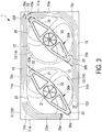
FIG. 3 is a diagram of the motor support member as viewed from the inside of the housing. -
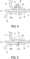
FIG. 4 is a cross-sectional view illustrating a structure that the motor support member and the bell mouth are directly joined. -
FIG. 5 is a cross-sectional view illustrating another example of a structure that the motor support member and the bell mouth are directly joined. -
FIG. 6 is a diagram illustrating a first modified example of an embodiment of an outdoor unit of the air conditioning system of the present disclosure, and is a perspective view of a motor support member disposed in a bell mouth of the outdoor unit as viewed from the inside of the housing. -
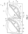
FIG. 7 is a diagram illustrating a second modified example of an embodiment of the outdoor unit of the air conditioning system of the present disclosure, and is a perspective view of a reinforcing member that is disposed on a base plate of the outdoor unit as viewed from the inside of the housing. -
FIG. 8 is a diagram illustrating a third modified example of an embodiment of the outdoor unit of the air conditioning system of the present disclosure, and is a diagram of the motor support member of the outdoor unit as viewed from the inside of the housing. - Hereinafter, an embodiment of an outdoor unit of an air conditioning system according to the present invention will be described with reference to the drawings.
- As illustrated in
FIG. 1 , theoutdoor unit 1 of the air conditioning system includes ahousing 10, abell mouth 12, afan 20, a motor 21 (seeFIG. 2 andFIG. 3 ), and aheat exchanger 15. - In
FIG. 2 , themotor support member 30A on the right side is different from themotor support member 30A on the left side, and a state that themotor 21 is not mounted is illustrated. - The
housing 10 has a rectangular parallelepiped shape, and abase plate 11 formed from a metal plate is disposed on one surface of thehousing 10. - The
bell mouth 12 is fixed to thebase plate 11 of thehousing 10. Thebell mouth 12 is cylindrical, and aflange part 12a that protrudes outward at the base end part of thebell mouth 12 is integrally formed. Thebell mouth 12 is fixed to thebase plate 11 in a state that theflange part 12a abutting against thebase plate 11. A through hole 14 (seeFIG. 2 andFIG. 3 ) that communicates with the openingpart 13 inside thebell mouth 12 is formed in thebase plate 11. - In this embodiment, the
base plate 11 has a rectangular shape, and two of thebell mouths 12 are arranged side by side at gaps along the long side direction of thebase plate 11. - The
fan 20 is installed inside the openingpart 13 of eachbell mouth 12. Thefan 20 integrally includes aboss 22 formed at a central part of thefan 20 and a plurality ofblades 23 disposed in the circumferential direction on the outer peripheral side of theboss 22. - As illustrated in
FIG. 2 , themotor 21 is arranged inside thehousing 10 with respect to thefan 20. Themotor 21 is arranged coaxially with theboss 22 of thefan 20, and thedrive shaft 21s is coupled to theboss 22. Themotor 21 rotationally drives thefan 20 by causing the drive shaft to rotate by a current supplied from the outside. - The
motor 21 is fixed to thebell mouth 12 by amotor support member 30A, which will be described in detail below. Note that inFIG. 2 , themotor support member 30A on the right side is different from themotor support member 30A on the left side, and a state that themotor 21 is not mounted is illustrated. - As illustrated in
FIG. 3 , theheat exchanger 15 is disposed in a pair of two so as to face each other across the openingparts bell mouths heat exchanger 15 and the indoor unit constituting the air conditioning system flows in theheat exchanger 15. - Each
heat exchanger 15 is substantially L-shaped and includes a firststraight line part 15a that extends along theshort side 11a of thebase plate 11, a secondstraight line part 15b that extends along along side 11b orthogonal to theshort side 11a of thebase plate 11, and acurved part 15c formed between the firststraight line part 15a and the secondstraight line part 15b and that extends along the outer perimeter part of theopening part 13 of one of thebell mouths 12. - The
motor support member 30A is disposed so as to straddle theopening part 13 of thebell mouth 12. Themotor support member 30A includes anarm part 31 and a fixingbracket FIG. 3 , themotor support member 30A on the right side is different from themotor support member 30A on the left side, and a state that themotor 21 is not mounted is illustrated. - The
arm part 31 extends so as to straddle theopening part 13 in a radial direction. Amotor base member 33 that fixes themotor 21 is integrally formed in the central part of thearm part 31. - The fixing
bracket arm part 31. - As illustrated in
FIG. 4 , each fixingbracket 32 is arranged so as to face theflange part 12a of thebell mouth 12 across thebase plate 11. The fixingbracket 32 of themotor support member 30A and theflange part 12a of thebell mouth 12 are coupled by passing thestud bolt 35 disposed on the fixingbracket 32 side through thebase plate 11 and theflange part 12a, and screwing thenut 36 to the tip part of thestud bolt 35. - Such a
motor support member 30A can be formed, for example, by bending a metal plate. - Here, instead of the configuration illustrated in
FIG. 4 , as illustrated inFIG. 5 , abolt 37 may be inserted through thebase plate 11 from theflange part 12a side of thebell mouth 12, and thetip part 37a of thebolt 37 is screwed into the fixingbracket 32 of themotor support member 30A. - As illustrated in
FIG. 3 , oneend 30a of themotor support member 30A is arranged between theend parts heat exchangers motor support member 30A straddles theopening part 13 in the radial direction, and theother end part 30b is arranged in the vicinity of the intermediate part of the secondstraight line part 15b of theheat exchanger 15. - According to the configuration described above, a pair of two
heat exchangers part 13 of thebell mouth 12 and in order to increase the heat exchange efficiency, when eachheat exchanger 15 is brought closer to theopening part 13, the gap between theheat exchanger 15, particularly thecurved part 15c, and theopening part 13 becomes small. In contrast, since oneend part 30a of themotor support member 30A is arranged between theend parts heat exchangers 15, it is not necessary to arrange the oneend 30a of themotor support member 30A in the gap between thecurved part 15c of theheat exchanger 15 and theopening part 13. Accordingly, the gap between the openingpart 13 of thebell mouth 12 and thecurved part 15c of theheat exchanger 15 can be narrowed to arrange themotor support member 30A. As a result, the heat exchange efficiency in theheat exchanger 15 can be increased. - Further, by directly joining the
motor support member 30A to thebell mouth 12, the position accuracy of themotor support member 30A and thebell mouth 12 can be improved. As a result, the gap between thefan 20 driven by themotor 21 supported by themotor support member 30A and thebell mouth 12 can be narrowed. Therefore, air can flow efficiently by thefan 20 and heat exchange efficiency in theheat exchanger 15 can be increased. - Further, by integrally forming the
motor base member 33 with themotor support member 30A, compared to a case where themotor base member 33 is a separate component from themotor support member 30A, the man hour of assembly can be reduced. - Note that in the embodiment described above, the
motor base member 33 is integrally formed with themotor support member 30A, but the present disclosure is not limited to this. For example, as illustrated inFIG. 6 , themotor support member 30B may be configured to include a pair of twopipe members opening part 13, and the plate-shapedmotor base member 39 may be welded to thesepipe members FIG. 6 , themotor support member 30B on the right side is different from themotor support member 30B on the left side, and state that themotor 21 is not mounted is illustrated. - Further, as illustrated in
FIG. 7 , a reinforcingmember 40A that reinforces thebase plate 11 may be provided on the outer peripheral side of thebell mouth 12. Note that, inFIG. 7 , themotor 21 mounted on themotor support member 30A is omitted. - As described in the above embodiment, when a plurality of sets of the
bell mouth 12, thefan 20, themotor 21, and themotor support member 30A are disposed in thesame base plate 11, the strength of thebase plate 11 is reduced particularly between the openingparts adjacent bell mouths base plate 11 sometimes resonates when thefan 20 rotates. - Therefore, the reinforcing
member 40A is arranged between thebell mouths - The reinforcing
member 40A integrally includes amain part 41 that extends in the direction of theshort side 11a of thebase plate 11, anextension part 42 extending on one side in the direction of thelong side 11b at one end part of themain part 41, and anextension part 43 extending on the other side in the direction of the long side at the other end part of themain part 41. The reinforcingmember 40A is formed in a rib-like shape that rises inside thehousing 10 orthogonal to thebase plate 11. Themain part 41 and theextension part member 40A are fixed to thebase plate 11. - According to such a configuration, by reinforcing the
base plate 11 by the reinforcingmember 40A, thebase plate 11 can be suppressed from resonating at the time of rotation of thefan 20. - Since the strength is reduced, in particular, between the opening
parts adjacent bell mouths member 40A between thebell mouths base plate 11 in this part can be efficiently reinforced. Therefore, thebase plate 11 can be effectively suppressed from resonating at the time of rotation of thefan 20. - In the embodiment described above, although a plurality of sets of the
bell mouth 12, thefan 20, themotor 21, and themotor support members same base plate 11, however, as illustrated inFIG. 8 , thebell mouth 12, thefan 20, themotor 21, and themotor support member 30A may be provided in a single set. - In this case, the
heat exchanger 15 is disposed in a pair of two so as to face each other across the openingpart 13 of thebell mouth 12. Eachheat exchanger 15 is substantially L-shaped and includes a firststraight line part 15g that extends along oneside 11g of thebase plate 11, a secondstraight line part 15h that extends along anotherside 11h orthogonal to the oneside 11g of thebase plate 11, and acurved part 15c formed between the firststraight line part 15g and the secondstraight line part 15h and that extends along the outer perimeter part of theopening part 13 of one of thebell mouth 12. Then, oneend part 30a and theother end part 30b of themotor support member 30A are arranged between theend parts heat exchangers - As a result, similar to the embodiment described above, the gap between the opening
part 13 of thebell mouth 12 and thecurved part 15c of theheat exchanger 15 can be narrowed. As a result, the heat exchange efficiency in theheat exchanger 15 can be increased. - In addition, in the configuration illustrated in
FIG. 8 , when the reinforcingmember 40B is disposed, an L-shaped reinforcingmember 40B may be disposed in the vicinity of the part where theend parts heat exchangers -
- 1 Outdoor Unit
- 10 Housing
- 11 Base Plate
- 12 Bell Mouth
- 13 Opening Part
- 15 Heat Exchanger
- 15c Curved Part
- 15e, 15f End Part
- 20 Fan
- 21 Motor
- 30A, 30B Motor Support Member
- 30a One End Part
- 30b Other End Part
- 33, 39 Motor Base Member
- 40A, 40B Reinforcing Member
Claims (7)
- An outdoor unit of an air conditioning system, comprising:a cylindrical bell mouth disposed to a base plate that constitutes part of a housing;a fan disposed inside the bell mouth;a motor that is installed in a central part of the fan and rotatably drives the fan;a motor support member disposed so as to straddle an opening part of the bell mouth to support the motor; andheat exchangers disposed in a pair of two so as to face each other across the opening part of the bell mouth, whereinat least one end part of the motor support member is arranged between end parts of the pair of two heat exchangers.
- The outdoor unit of the air conditioning system according to claim 1, wherein
the motor support member is directly joined to the bell mouth. - The outdoor unit of the air conditioning system according to claim 1 or 2, wherein
the motor support member is integrally formed with a motor base member that fixes the motor. - The outdoor unit of the air conditioning system according to any one of claims 1 to 3, further comprising:
a reinforcing member that is disposed on an outer peripheral side of the bell mouth and configured to reinforce the base plate. - The outdoor unit of the air conditioning system according to claim 4, wherein
a plurality of sets of the bell mouths, the fans, the motors, and the motor support members are disposed in the same base plate, the reinforcing member is arranged between the bell mouths adjacent to each other. - An outdoor unit of an air conditioning system, comprising:a cylindrical bell mouth disposed to a base plate that constitutes part of a housing; a fan disposed inside the bell mouth;a motor that is installed in a central part of the fan and rotatably drives the fan; anda motor support member disposed so as to straddle an opening part of the bell mouth to support the motor, whereinthe motor support member is directly joined to the bell mouth.
- An outdoor unit of an air conditioning system, comprising:a cylindrical bell mouth disposed to a base plate that constitutes part of a housing; a fan disposed inside the bell mouth;a motor that is installed in a central part of the fan and rotatably drives the fan; a motor support member disposed so as to straddle an opening part of the bell mouth to support the motor; anda reinforcing member that is disposed on an outer peripheral side of the bell mouth and configured to reinforce the base plate, whereina plurality of sets of the bell mouths, the fans, the motors, and the motor support members are disposed in the same base plate, the reinforcing member is arranged between the bell mouths adjacent to each other.
Applications Claiming Priority (2)
| Application Number | Priority Date | Filing Date | Title |
|---|---|---|---|
| JP2017097241A JP2018194216A (en) | 2017-05-16 | 2017-05-16 | Air conditioner outdoor unit |
| PCT/JP2018/014520 WO2018211849A1 (en) | 2017-05-16 | 2018-04-05 | Outdoor unit of air conditioning system |
Publications (1)
| Publication Number | Publication Date |
|---|---|
| EP3531033A1 true EP3531033A1 (en) | 2019-08-28 |
Family
ID=64273685
Family Applications (1)
| Application Number | Title | Priority Date | Filing Date |
|---|---|---|---|
| EP18801265.2A Withdrawn EP3531033A1 (en) | 2017-05-16 | 2018-04-05 | Outdoor unit of air conditioning system |
Country Status (4)
| Country | Link |
|---|---|
| EP (1) | EP3531033A1 (en) |
| JP (1) | JP2018194216A (en) |
| CN (1) | CN109923350A (en) |
| WO (1) | WO2018211849A1 (en) |
Families Citing this family (1)
| Publication number | Priority date | Publication date | Assignee | Title |
|---|---|---|---|---|
| CN111256216A (en) * | 2020-01-21 | 2020-06-09 | 珠海格力电器股份有限公司 | Air conditioner outer unit and air conditioner with same |
Family Cites Families (8)
| Publication number | Priority date | Publication date | Assignee | Title |
|---|---|---|---|---|
| AU528375B2 (en) | 1978-06-07 | 1983-04-28 | Allegheny Ludlum Industries Inc. | Protecting ferritic stainless steel from crevice and pitting corrosion |
| JPS5878095A (en) * | 1981-11-02 | 1983-05-11 | Mitsui Toatsu Chem Inc | Heat exchanger |
| JPH02100137U (en) * | 1989-01-27 | 1990-08-09 | ||
| JPH05157289A (en) * | 1991-12-10 | 1993-06-22 | Mitsubishi Electric Corp | Air conditioner |
| JP3721874B2 (en) | 1999-08-04 | 2005-11-30 | オムロン株式会社 | Axle load measuring device |
| JP5877363B2 (en) * | 2011-06-13 | 2016-03-08 | パナソニックIpマネジメント株式会社 | Air conditioner outdoor unit |
| JP5877364B2 (en) * | 2011-06-13 | 2016-03-08 | パナソニックIpマネジメント株式会社 | Air conditioner outdoor unit |
| JP6535499B2 (en) * | 2015-04-10 | 2019-06-26 | 東芝キヤリア株式会社 | Refrigeration cycle device |
-
2017
- 2017-05-16 JP JP2017097241A patent/JP2018194216A/en active Pending
-
2018
- 2018-04-05 CN CN201880004262.1A patent/CN109923350A/en active Pending
- 2018-04-05 WO PCT/JP2018/014520 patent/WO2018211849A1/en not_active Ceased
- 2018-04-05 EP EP18801265.2A patent/EP3531033A1/en not_active Withdrawn
Also Published As
| Publication number | Publication date |
|---|---|
| JP2018194216A (en) | 2018-12-06 |
| WO2018211849A1 (en) | 2018-11-22 |
| CN109923350A (en) | 2019-06-21 |
Similar Documents
| Publication | Publication Date | Title |
|---|---|---|
| CN102686912B (en) | Cooling fan of drive device and cooling fan structure of same | |
| CN204943828U (en) | A kind of wind deflector transmission device and air-conditioner thereof | |
| US10113551B2 (en) | Axial flow fan | |
| EP2889543A1 (en) | Air conditioning outdoor unit | |
| CN204227576U (en) | The front board component of air-conditioner outdoor unit and air-conditioner outdoor unit | |
| CN104421189A (en) | Blowing-in fan and air conditioner with same | |
| EP3657025B1 (en) | Cross-flow impeller device and cooling fan | |
| JP2002349476A (en) | Series fan | |
| WO2018211849A1 (en) | Outdoor unit of air conditioning system | |
| JP5949750B2 (en) | Cross flow fan | |
| CN209341539U (en) | Wind deflector fixing structure | |
| CN102549344B (en) | Outdoor unit for air conditioner and manufacturing method for same | |
| CN206801951U (en) | Fan assembly and air-cooled ducted air conditioner | |
| CN207920969U (en) | Spiral case component and air-conditioning equipment | |
| CN107306513A (en) | Motor and ventilation fan | |
| US20230029281A1 (en) | Fastening apparatus for fastening a ventilator to a carrier structure | |
| JP6502632B2 (en) | Outdoor unit and air conditioner provided with this outdoor unit | |
| CN206831701U (en) | A kind of electric machine support and air conditioner | |
| EP3098453A1 (en) | Turbofan and air-conditioning device | |
| JP5599246B2 (en) | Ventilation fan | |
| JP2020133457A (en) | Blower | |
| JPWO2016157471A1 (en) | Blower and air conditioner | |
| CN218991932U (en) | Rotary support mechanism for fan head | |
| CN222746290U (en) | Gap control tool | |
| CN205243884U (en) | Bilobed wheel centrifugal fan |
Legal Events
| Date | Code | Title | Description |
|---|---|---|---|
| PUAI | Public reference made under article 153(3) epc to a published international application that has entered the european phase |
Free format text: ORIGINAL CODE: 0009012 |
|
| 17P | Request for examination filed |
Effective date: 20190524 |
|
| AK | Designated contracting states |
Kind code of ref document: A1 Designated state(s): AL AT BE BG CH CY CZ DE DK EE ES FI FR GB GR HR HU IE IS IT LI LT LU LV MC MK MT NL NO PL PT RO RS SE SI SK SM TR |
|
| AX | Request for extension of the european patent |
Extension state: BA ME |
|
| STAA | Information on the status of an ep patent application or granted ep patent |
Free format text: STATUS: THE APPLICATION HAS BEEN WITHDRAWN |
|
| 18W | Application withdrawn |
Effective date: 20191107 |