EP3530995A1 - Poppet valve, hydraulic machine, hydraulic transmission, renewable-energy type power generating apparatus, and method of producing poppet valve - Google Patents
Poppet valve, hydraulic machine, hydraulic transmission, renewable-energy type power generating apparatus, and method of producing poppet valve Download PDFInfo
- Publication number
- EP3530995A1 EP3530995A1 EP18177350.8A EP18177350A EP3530995A1 EP 3530995 A1 EP3530995 A1 EP 3530995A1 EP 18177350 A EP18177350 A EP 18177350A EP 3530995 A1 EP3530995 A1 EP 3530995A1
- Authority
- EP
- European Patent Office
- Prior art keywords
- poppet
- valve
- thermally sprayed
- sprayed layer
- end surface
- Prior art date
- Legal status (The legal status is an assumption and is not a legal conclusion. Google has not performed a legal analysis and makes no representation as to the accuracy of the status listed.)
- Granted
Links
Images




Classifications
-
- F—MECHANICAL ENGINEERING; LIGHTING; HEATING; WEAPONS; BLASTING
- F16—ENGINEERING ELEMENTS AND UNITS; GENERAL MEASURES FOR PRODUCING AND MAINTAINING EFFECTIVE FUNCTIONING OF MACHINES OR INSTALLATIONS; THERMAL INSULATION IN GENERAL
- F16K—VALVES; TAPS; COCKS; ACTUATING-FLOATS; DEVICES FOR VENTING OR AERATING
- F16K31/00—Actuating devices; Operating means; Releasing devices
- F16K31/02—Actuating devices; Operating means; Releasing devices electric; magnetic
- F16K31/06—Actuating devices; Operating means; Releasing devices electric; magnetic using a magnet, e.g. diaphragm valves, cutting off by means of a liquid
- F16K31/0644—One-way valve
- F16K31/0655—Lift valves
- F16K31/0658—Armature and valve member being one single element
-
- F—MECHANICAL ENGINEERING; LIGHTING; HEATING; WEAPONS; BLASTING
- F04—POSITIVE - DISPLACEMENT MACHINES FOR LIQUIDS; PUMPS FOR LIQUIDS OR ELASTIC FLUIDS
- F04B—POSITIVE-DISPLACEMENT MACHINES FOR LIQUIDS; PUMPS
- F04B53/00—Component parts, details or accessories not provided for in, or of interest apart from, groups F04B1/00 - F04B23/00 or F04B39/00 - F04B47/00
- F04B53/10—Valves; Arrangement of valves
- F04B53/12—Valves; Arrangement of valves arranged in or on pistons
- F04B53/125—Reciprocating valves
- F04B53/129—Poppet valves
-
- F—MECHANICAL ENGINEERING; LIGHTING; HEATING; WEAPONS; BLASTING
- F16—ENGINEERING ELEMENTS AND UNITS; GENERAL MEASURES FOR PRODUCING AND MAINTAINING EFFECTIVE FUNCTIONING OF MACHINES OR INSTALLATIONS; THERMAL INSULATION IN GENERAL
- F16K—VALVES; TAPS; COCKS; ACTUATING-FLOATS; DEVICES FOR VENTING OR AERATING
- F16K1/00—Lift valves or globe valves, i.e. cut-off apparatus with closure members having at least a component of their opening and closing motion perpendicular to the closing faces
- F16K1/32—Details
- F16K1/34—Cutting-off parts, e.g. valve members, seats
- F16K1/44—Details of seats or valve members of double-seat valves
-
- F—MECHANICAL ENGINEERING; LIGHTING; HEATING; WEAPONS; BLASTING
- F16—ENGINEERING ELEMENTS AND UNITS; GENERAL MEASURES FOR PRODUCING AND MAINTAINING EFFECTIVE FUNCTIONING OF MACHINES OR INSTALLATIONS; THERMAL INSULATION IN GENERAL
- F16K—VALVES; TAPS; COCKS; ACTUATING-FLOATS; DEVICES FOR VENTING OR AERATING
- F16K27/00—Construction of housing; Use of materials therefor
- F16K27/02—Construction of housing; Use of materials therefor of lift valves
- F16K27/029—Electromagnetically actuated valves
-
- F—MECHANICAL ENGINEERING; LIGHTING; HEATING; WEAPONS; BLASTING
- F16—ENGINEERING ELEMENTS AND UNITS; GENERAL MEASURES FOR PRODUCING AND MAINTAINING EFFECTIVE FUNCTIONING OF MACHINES OR INSTALLATIONS; THERMAL INSULATION IN GENERAL
- F16K—VALVES; TAPS; COCKS; ACTUATING-FLOATS; DEVICES FOR VENTING OR AERATING
- F16K31/00—Actuating devices; Operating means; Releasing devices
- F16K31/02—Actuating devices; Operating means; Releasing devices electric; magnetic
- F16K31/06—Actuating devices; Operating means; Releasing devices electric; magnetic using a magnet, e.g. diaphragm valves, cutting off by means of a liquid
- F16K31/0675—Electromagnet aspects, e.g. electric supply therefor
-
- F—MECHANICAL ENGINEERING; LIGHTING; HEATING; WEAPONS; BLASTING
- F16—ENGINEERING ELEMENTS AND UNITS; GENERAL MEASURES FOR PRODUCING AND MAINTAINING EFFECTIVE FUNCTIONING OF MACHINES OR INSTALLATIONS; THERMAL INSULATION IN GENERAL
- F16K—VALVES; TAPS; COCKS; ACTUATING-FLOATS; DEVICES FOR VENTING OR AERATING
- F16K31/00—Actuating devices; Operating means; Releasing devices
- F16K31/02—Actuating devices; Operating means; Releasing devices electric; magnetic
- F16K31/06—Actuating devices; Operating means; Releasing devices electric; magnetic using a magnet, e.g. diaphragm valves, cutting off by means of a liquid
- F16K31/0686—Braking, pressure equilibration, shock absorbing
- F16K31/0693—Pressure equilibration of the armature
-
- F—MECHANICAL ENGINEERING; LIGHTING; HEATING; WEAPONS; BLASTING
- F03—MACHINES OR ENGINES FOR LIQUIDS; WIND, SPRING, OR WEIGHT MOTORS; PRODUCING MECHANICAL POWER OR A REACTIVE PROPULSIVE THRUST, NOT OTHERWISE PROVIDED FOR
- F03D—WIND MOTORS
- F03D9/00—Adaptations of wind motors for special use; Combinations of wind motors with apparatus driven thereby; Wind motors specially adapted for installation in particular locations
- F03D9/20—Wind motors characterised by the driven apparatus
- F03D9/28—Wind motors characterised by the driven apparatus the apparatus being a pump or a compressor
-
- F—MECHANICAL ENGINEERING; LIGHTING; HEATING; WEAPONS; BLASTING
- F05—INDEXING SCHEMES RELATING TO ENGINES OR PUMPS IN VARIOUS SUBCLASSES OF CLASSES F01-F04
- F05B—INDEXING SCHEME RELATING TO WIND, SPRING, WEIGHT, INERTIA OR LIKE MOTORS, TO MACHINES OR ENGINES FOR LIQUIDS COVERED BY SUBCLASSES F03B, F03D AND F03G
- F05B2260/00—Function
- F05B2260/40—Transmission of power
- F05B2260/406—Transmission of power through hydraulic systems
-
- H—ELECTRICITY
- H01—ELECTRIC ELEMENTS
- H01F—MAGNETS; INDUCTANCES; TRANSFORMERS; SELECTION OF MATERIALS FOR THEIR MAGNETIC PROPERTIES
- H01F7/00—Magnets
- H01F7/06—Electromagnets; Actuators including electromagnets
- H01F7/08—Electromagnets; Actuators including electromagnets with armatures
- H01F7/16—Rectilinearly-movable armatures
- H01F2007/1661—Electromagnets or actuators with anti-stick disc
-
- Y—GENERAL TAGGING OF NEW TECHNOLOGICAL DEVELOPMENTS; GENERAL TAGGING OF CROSS-SECTIONAL TECHNOLOGIES SPANNING OVER SEVERAL SECTIONS OF THE IPC; TECHNICAL SUBJECTS COVERED BY FORMER USPC CROSS-REFERENCE ART COLLECTIONS [XRACs] AND DIGESTS
- Y02—TECHNOLOGIES OR APPLICATIONS FOR MITIGATION OR ADAPTATION AGAINST CLIMATE CHANGE
- Y02E—REDUCTION OF GREENHOUSE GAS [GHG] EMISSIONS, RELATED TO ENERGY GENERATION, TRANSMISSION OR DISTRIBUTION
- Y02E10/00—Energy generation through renewable energy sources
- Y02E10/70—Wind energy
- Y02E10/72—Wind turbines with rotation axis in wind direction
-
- Y—GENERAL TAGGING OF NEW TECHNOLOGICAL DEVELOPMENTS; GENERAL TAGGING OF CROSS-SECTIONAL TECHNOLOGIES SPANNING OVER SEVERAL SECTIONS OF THE IPC; TECHNICAL SUBJECTS COVERED BY FORMER USPC CROSS-REFERENCE ART COLLECTIONS [XRACs] AND DIGESTS
- Y02—TECHNOLOGIES OR APPLICATIONS FOR MITIGATION OR ADAPTATION AGAINST CLIMATE CHANGE
- Y02P—CLIMATE CHANGE MITIGATION TECHNOLOGIES IN THE PRODUCTION OR PROCESSING OF GOODS
- Y02P70/00—Climate change mitigation technologies in the production process for final industrial or consumer products
- Y02P70/50—Manufacturing or production processes characterised by the final manufactured product
Definitions
- the present disclosure relates to a poppet valve, a hydraulic machine including the poppet valve, a hydraulic transmission including the hydraulic machine, a renewable-energy type power generating apparatus including the hydraulic mission, and a method of producing a poppet valve.
- a wind turbine power generating apparatus which is a renewable-energy type power generating apparatus, may include a hydraulic transmission.
- a hydraulic transmission uses pressurized oil to convert rotational energy of a rotor that rotates in response to a wind force into mechanical energy, and thereby drives a generator.
- Patent Document 1 previously proposed by the present applicant, discloses a hydraulic transmission for a wind turbine power generating apparatus including a hydraulic pump configured to be driven by a rotor and pressurize working oil, and a hydraulic motor configured to drive a generator with high pressure oil supplied from the hydraulic pump through a high pressure oil flow passage.
- the hydraulic transmission is configured to return low pressure oil after driving the generator to the hydraulic pump via a low pressure oil flow passage.
- the hydraulic pump and the hydraulic motor each include a working chamber formed by a cylinder and a piston, and a poppet valve (solenoid valve) for controlling a communication state between the working chamber and the high pressure oil flow passage or the low pressure oil flow passage.
- Patent Document 1 discloses a diagnosis system in which, to prevent response delay of a magnetic poppet (valve body) caused by a fitting effect or residual magnetism between the poppet and a magnetic valve casing that makes contact with the poppet on a valve opening operation of the poppet, a plate member (position-restricting part) is disposed between the poppet and the valve casing. Accordingly, direct contact between the poppet and the valve casing is avoided to improve the responsiveness of the poppet, and damage such as wear and settling of the position-restricting part, for instance, can be detected from a change in response delay of the poppet.
- a plate member position-restricting part
- Patent Document 2 discloses providing an uneven portion on an end surface of a poppet (valve body) or a contact surface of a valve casing that makes contact with the poppet, to address deterioration of the responsiveness of the poppet valve due to a differential pressure between the front side and the back side of the poppet valve on a valve opening or closing operation of the poppet.
- This uneven portion a space is formed between the poppet and the contact surface. Accordingly, the differential pressure between the front side and the back side of the poppet is reduced, and thereby deterioration of the responsiveness of the poppet can be suppressed.
- Patent Document 2 discloses a diagnosis system capable of detecting damage in the position-restricting part, it does not disclose an approach for suppressing damage in the position-restricting part.
- an object of at least one embodiment is to suppress response delay of a poppet due to aging or damage in a position-restricting part.
- an end surface of the poppet opposite to the valve seat refers to an end surface that is further from the valve seat, of the two surfaces of the poppet in the moving direction of the poppet.
- the end surface of the poppet and the contact surface of the first valve casing make contact with each other via the thermally sprayed layer when the poppet valve is in a valve open state, and separate from each other by a valve-closing operation of the poppet.
- the thermally sprayed layer often makes contact with and separates from the contact surface of the first valve casing or the poppet end surface, and thus in an environment in which aging such as wear and settling is likely to occur.
- the thermally sprayed layer, the poppet end surface and the contact surface of the first valve casing satisfy the above relationship of hardness, and thus have a substantially equivalent hardness.
- the thermally sprayed layer including a non-magnetic material is interposed between the poppet end surface and the contact surface of the first valve casing, and thus it is possible to reduce the attractive force due to magnetism remaining on the poppet or the first valve casing on a closing operation of the poppet, which also improves the responsiveness of the poppet.
- the thermally sprayed layer makes close surface-contact with the contact surface of the first valve casing or the poppet end surface in a valve-opened state
- the thermally sprayed layer separates from the contact surface of the first valve casing or the poppet end surface on a valve closing operation
- brief expansion occurs in the space between the thermally sprayed layer and the contact surface of the first valve casing or the poppet end surface, which reduces the pressure and generates a pressure differential between the thermally sprayed layer and the valve-seat side surface of the poppet.
- This pressure differential leads to deterioration of responsiveness in a valve-closing operation.
- the thermally sprayed layer is in contact with the poppet end surface or the contact surface of the first valve casing, and the fluid around the poppet is capable of flowing into the space, it is possible to reduce a pressure differential between the poppet end surface and the valve-seat side surface even further, and improve the responsiveness of the valve operation more effectively.
- the uneven portion by photo etching, it is possible to form a micron-size complex uneven portion precisely as designed. Furthermore, it is possible to perform precise machine processing without forming burrs and strains, or causing hardening, etc.
- an expression of relative or absolute arrangement such as “in a direction”, “along a direction”, “parallel”, “orthogonal”, “centered”, “concentric” and “coaxial” shall not be construed as indicating only the arrangement in a strict literal sense, but also includes a state where the arrangement is relatively displaced by a tolerance, or by an angle or a distance whereby it is possible to achieve the same function.
- an expression of an equal state such as “same” “equal” and “uniform” shall not be construed as indicating only the state in which the feature is strictly equal, but also includes a state in which there is a tolerance or a difference that can still achieve the same function.
- an expression of a shape such as a rectangular shape or a cylindrical shape shall not be construed as only the geometrically strict shape, but also includes a shape with unevenness or chamfered corners within the range in which the same effect can be achieved.
- FIG. 1 is a schematic diagram of a wind turbine power generating apparatus 10 according to an embodiment.
- the wind turbine power generating apparatus 10 includes a rotor 12 configured to rotate in response to wind, which is a renewable energy, a hydraulic transmission 14 for transmitting rotation of the rotor 12, and a generator 16 for generating electric power.
- the rotor 12 includes at least one blade 18, and a hub 20 to which the at least one blade 18 is mounted.
- the hydraulic transmission 14 includes a hydraulic pump 24 coupled to the rotor 12 via a rotational shaft 22 and configured to generate high pressure oil, a hydraulic motor 26 configured to be driven by the high pressure oil supplied from the hydraulic pump 24, a high pressure oil flow passage 28 for supplying high pressure oil from the hydraulic pump 24 to the hydraulic motor 26, and a low pressure oil flow passage 30 for returning low pressure oil discharged from the hydraulic motor 26 to the hydraulic pump 24.
- the generator 16 is coupled to the hydraulic motor 26 via an output shaft of the hydraulic motor 26.
- the generator 16 is a synchronous generator driven by the hydraulic motor 26, and is connected to a utility grid.
- the hydraulic transmission 14 and the generator 16 are disposed inside a nacelle 29 disposed on an upper part of the tower 31.
- the rotational energy of the rotor 12 is inputted into the generator 16 via the hydraulic transmission 14 including the hydraulic pump 24 and the hydraulic motor 26, and electric power is generated by the generator 16.
- the entire rotor 12 rotates due to the power of the wind, so that the hydraulic pump 24 is driven by the rotor 12 to pressurize working oil, thereby producing high pressure working oil (pressurized oil).
- the pressurized oil produced by the hydraulic pump 24 is supplied to the hydraulic motor 26 via the high pressure oil flow passage 28, and drives the hydraulic motor 26. Electric power is generated by the generator 16 connected to the hydraulic motor 26 via the output shaft.
- the low pressure working oil having performed work in the hydraulic motor 26 returns to the hydraulic pump 24 via the low pressure oil flow passage 30.
- the hydraulic pump 24 and the hydraulic motor 26 may be of a variable-displacement type whereby the displacement is adjustable.
- At least one of the above described hydraulic pump 24 or the hydraulic motor 26 is a hydraulic machine 40 described below.
- FIG. 2 is a schematic configuration diagram of a hydraulic machine 40 according to an embodiment.
- the hydraulic machine 40 includes at least one cylinder 42 and a piston which reciprocates inside the cylinder 42.
- the cylinder 42 and the piston 44 form a working chamber 46.
- the working chamber 46 is in communication with a high pressure oil flow passage 28 and a low pressure oil flow passage 30 (external passage).
- a high pressure valve 32 is disposed in the high pressure oil flow passage 28, and a low pressure valve 34 is disposed in the low pressure oil flow passage 30. As the high pressure valve 32 and the low pressure valve 34 open and close, the communication state between the working chamber 46 and the high pressure oil flow passage 28 and the low pressure oil flow passage 30 is controlled.
- the hydraulic machine 40 further includes a rotational shaft 48, and a cam 50 (conversion mechanism) for converting rotational motion of the rotational shaft 48 and reciprocal motion of the piston 44, or vice versa.
- the cam 50 is an eccentric cam disposed eccentrically from the axial center O of the rotational shaft 48. While the piston 44 performs a set of upward and downward movement, the rotational shaft 48 to which the cam 50 is mounted performs one revolution.
- a plurality of cylinders 42 and a plurality of pistons 44 are disposed along the circumferential direction of the hydraulic machine 40.
- the high pressure valves 32 and the low pressure valves 34 are controlled in accordance with reciprocal motion of the pistons 44, so that a pressure of each working chamber 46 changes periodically in accordance with the reciprocal motion of the pistons 44.
- configuration of the high pressure valve 32 and the low pressure valve 34 of the hydraulic machine 40 will be described, along with a periodical change of the working chamber pressure caused by opening-and-closing control on the valves.
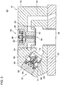
- FIG. 3 is a schematic cross-sectional view of a configuration of the high pressure valve 32 and the low pressure valve 34.
- both of the high pressure valve 32 and the low pressure valve 34 are solenoid valves
- FIG. 3 is a view of a situation in which the high pressure valve 32 is closed and the low pressure valve 34 is open.
- the high pressure valve 32, the low pressure valve 34, and a casing 43 housing the valves may be unitized and configured as a valve unit 41.
- the high pressure valve 32 illustrated in FIG. 3 includes an actuator 60 for moving the valve body 58 between a valve-open position and a valve-closed position, a biasing member 66, and a valve seat 56.
- the high pressure valve 32 is a poppet solenoid valve of a normally-closed type, with the valve seat 56 disposed on a side adjacent to the working chamber 46 with respect to the valve body 58.
- the high pressure valve 32 is capable of switching the communication state between the working chamber 46 and the high pressure oil flow passage 28 (see FIG. 2 ) through an opening-and-closing operation of the valve body 58.
- the actuator 60 is a solenoid coil
- the biasing member 66 is a spring
- the valve body 58 includes a valve body having a poppet shape.
- the low pressure valve 34 illustrated in FIG. 3 includes a movable unit 84 including a valve body 80 and an armature 82, a solenoid coil 86, a spring 88, and a valve seat 90.
- the low pressure valve 34 is a poppet solenoid valve (poppet valve) of normally-open type, with the valve body 80 disposed on the side adjacent to the working chamber 46 with respect to the valve seat 90.
- the low pressure valve 34 is capable of switching the communication state between the working chamber 46 and the low pressure oil flow passage 30 (see FIG. 2 ) by movement of the movable unit 84 caused by an electromagnetic force of the solenoid coil 86 or a biasing force of the spring 88.
- the high pressure valve 32 and the low pressure valve 34 are controlled to open and close with control signals (open-close command) sent from a valve control part 76.
- the valve control part 76 provides the high pressure valve 32 and the low pressure valve 34 with control signals for the open-close command.
- the rotational shaft 48 is connected to the rotational shaft 22 of the rotor 12. As the rotational shaft 22 rotates, the rotational shaft 48 rotates. In response to rotation of the rotational shaft 48, the piston 44 reciprocates inside the working chamber 46 and thereby high pressure oil is generated. The generated high pressure oil is supplied to the hydraulic motor 26 via the high pressure oil flow passage 28.
- the rotational shaft 48 is coupled to the generator 16.
- the rotational shaft 48 is rotated by high pressure oil supplied to the plurality of working chambers 46 in sequence from the high pressure oil flow passage 28.
- the generator 16 In response to rotation of the rotational shaft 48, the generator 16 generates electric power.
- the high pressure valves 32 are disposed in a high pressure communication line 52 between the high pressure oil flow passage 28 and the respective working chambers 46, and configured to be capable of switching the communication state between the respective working chambers 46 and the high pressure oil flow passage 28.
- the low pressure valves 34 are disposed in a low pressure communication line 54 between the low pressure oil flow passage 30 and the respective working chambers 46, and configured to be capable of switching the communication state between the respective working chambers 46 and the low pressure oil flow passage 30.
- the poppet valves may be used as low pressure valves 34.
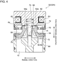
- the poppet valve 32 (32A, 32B, 32C, 32D, 32E) according to some embodiments includes a poppet (valve body) 58 disposed so as to face the valve seat 56, and is configured to be movable by the actuator 60.
- the actuator 60 is housed inside the first valve casing 62.
- the first valve casing 62 includes a contact surface 62a capable of making contact with an end surface 58a of the poppet 58, disposed opposite to the valve seat 56, on an valve-opening operation of the poppet 58, via a thermally sprayed layer 64.
- the thermally sprayed layer 64 includes a non-magnetic material and is formed on at least a part of the end surface 48a of the poppet 58 or the contact surface 62a of the first valve casing 62.
- the Vickers hardness Hv1 of the end surface 58a of the poppet 58 or the contact surface 62a of the first valve casing 62 and the Vickers hardness Hv2 of the thermally sprayed layer 64 have the following relationship (1): (Hv1-50Hv) ⁇ Hv2 ⁇ (Hv1+100Hv).
- the hardness of the thermally sprayed layer 64 is substantially equivalent to the hardness of the poppet end surface 58a or the contact surface 62a.
- the thermally sprayed layer 64 including a non-magnetic material is interposed between the poppet end surface 58a and the contact surface 62a, and thus it is possible to reduce an attractive force due to magnetism remaining on the poppet 58 or the first valve casing 62 on a closing operation of the poppet 58, which also improves the responsiveness of the poppet 58.
- thermally sprayed layer 64 may be formed on the poppet end surface 58a, or on the contact surface 62a of the first valve casing 62.
- thermally sprayed layer 64 By reducing the area of the thermally sprayed layer 64 and forming the thermally sprayed layer 64 partially on the poppet end surface 58a or the contact surface 62a, it is possible to reduce the fitting effect and the separation resistance of the thermally sprayed layer 64 with the poppet end surface 48a or the contact surface 62a. Thus, by reducing the area of the thermally sprayed layer 64 without impairing the original function of the thermally sprayed layer 64, it is also possible to improve the response delay of the poppet 58.
- the biasing member 66 is further provided, to bias the poppet 58 toward the valve seat 56.
- the poppet 58 and the first valve casing 62 include at least a portion made from a magnetic element.
- the actuator 60 includes a solenoid configured to generate an electromagnetic force that attracts the poppet 58 toward the first valve casing 62 against the biasing force applied by the biasing member 66 in an excited state.
- the poppet valve 32 is a normally-closed type solenoid valve, and the response speed of the valve-closing operation may decrease due to an attractive force generated by the residual magnetism of the first valve casing 62, even if power supply to the solenoid is stopped on a valve-closing operation.
- thermally sprayed layer 64 between the poppet end surface 58a in the valve-open position and the contact surface 62a magnetic-attractive surface
- the second valve casing 68 forming the valve seat 56 is provided, and an annular spacer 70 is disposed on the radially outer side of the poppet 58, between the first valve casing 62 and the second valve casing 68.
- the annular spacer 70 includes at least one communication flow passages f1 and f2 formed thereon, to bring the interior space housing the poppet 58 and the exterior space into communication. As the poppet 58 is disposed radially inside the annular spacer 70, it is possible to secure a suitable space to allow movement of the poppet 58.
- an inner flow passage is formed to bring the interior space and the exterior space of the annular spacer 70 into communication, and thus it is possible to form a smooth flow of a fluid between the communication flow passage f3 to be opened and closed by the poppet 58 and an external flow passage (e.g. the high pressure communication line 52 illustrated in FIG. 3 ) of the poppet valve 32.
- the poppet 58 includes at least one communication window 59 formed thereon, which is in communication with the communication flow passage f1, in the circumferential direction.
- the communication flow passage f3 is formed inside the second valve casing 68.
- the communication flow passages f1 and f2, and the communication flow passage f3 are brought into communication with one another by a valve-opening operation of the poppet 58, and the communication therebetween is shut off by a valve-closing operation of the poppet 58.
- the communication flow passages f1 and f2 are in communication with the high pressure oil flow passage 28, and the communication flow passage f3 is in communication with the working chamber 46.
- annular member 72 is disposed between the first valve casing 62 and the annular spacer 70.
- the poppet 58 has a rod through hole 58b formed along the operation direction of the poppet 58.
- a rod 74 is loosely fit into the rod through hole 58b, and guides the poppet 58 to a valve-closed position or a valve-open position.
- the poppet end surface 58a and the contact surface 62a are formed to have an annular shape centered at the rod through hole 58b, and the thermally sprayed layer 64 is formed in an annular shape in at least a part of the poppet end surface 58a or the contact surface 62a.
- a seat surface 75 (to be in contact with the valve seat 56) protruding toward the valve seat is formed on a valve-seat side surface of the poppet 58.
- the seat surface 75 is formed to have a double concentric shape, and makes contact with the valve seat 56 formed on the first valve casing 62 on a valve-closing operation of the poppet 58. Accordingly, it is possible to prevent leakage of working oil when the valve is closed.
- the base material of the non-magnetic material of the thermally sprayed layer 64 includes a material with a Vickers hardness of not less than 450.
- the thermally sprayed layer 64 having a high hardness, it is possible to suppress aging of the thermally sprayed layer 64, which makes it possible to suppress response delay of the poppet 58 due to aging of the thermally sprayed layer 64.
- the Rockwell hardness HRC of the thermally sprayed layer 64 after forming a coating is not less than 45.
- the thermally sprayed layer 64 after forming a coating having a high hardness, it is possible to suppress aging of the thermally sprayed layer 64, which makes it possible to suppress response delay of the poppet 58 due to aging of the thermally sprayed layer 64.
- the layer thickness of the thermally sprayed layer 64 is not less than 1mm.
- the thermally sprayed layer 64 having a layer thickness of not less than 1mm, it is possible to maintain the strength of the thermally sprayed layer 64 and thereby suppress aging of the thermally sprayed layer 64, which makes it possible to suppress response delay of the poppet due to aging of the thermally sprayed layer 64.
- the layer thickness of the thermally sprayed layer 64 may be not less than 4mm. Accordingly, it is possible to suppress aging of the thermally sprayed layer 64 even more effectively, which makes it possible to suppress response delay of the poppet due to aging of the thermally sprayed layer 64 effectively.
- the thermally sprayed layer 64 includes a cobalt-chromium alloy also containing tungsten, a nickel alloy, or a tungsten alloy.
- a cobalt-chromium alloy also containing tungsten has a Vickers hardness of 500 to 650Hv, and a nickel alloy and a tungsten alloy have a Vickers hardness of 600 to 700Hv, each alloy having a high hardness.
- the thermally sprayed layer 64 including at least one of the above materials, it is possible to suppress aging of the thermally sprayed layer 64, which makes it possible to suppress response delay of the poppet 58 due to aging of the thermally sprayed layer 64.
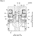
- FIG. 5 is a vertical cross-sectional view of the poppet valve 32 (32B) according to an embodiment
- FIG. 6 is a partially enlarged view of FIG. 5 .
- the contact surface 62a of the first valve casing 62 or the poppet end surface 58a capable of making contact with the thermally sprayed layer 64 includes an uneven portion 92. With the uneven portion 92, a space 's' is formed between the thermally sprayed layer 64 and the contact surface 62a or the poppet end surface 58a.
- thermally sprayed layer 64 makes close surface-contact with the contact surface 62a or the poppet end surface 58a in a valve-opened state
- the thermally sprayed layer 64 separates from the contact surface 62a or the poppet end surface 58a on a valve closing operation
- brief expansion occurs in the space 's' between the thermally sprayed layer 64 and the contact surface 62a or the poppet end surface 58a, which reduces the pressure and generates a pressure differential between the thermally sprayed layer 64 and the valve-seat side surface of the poppet 58.
- This pressure differential leads to deterioration of responsiveness in a valve-closing operation.
- valve-opening operation when the poppet end surface 58a approaches the contact surface 62a, brief compression may occur in the space between the above surfaces and increase the pressure therein, and the responsiveness of the valve-opening operation may decrease due to a pressure differential created between the poppet end surface 58a and the valve-seat side surface of the poppet 58.
- the thermally sprayed layer 64 by reducing the area of the thermally sprayed layer 64 and forming the thermally sprayed layer 64 partially on the poppet end surface 58a or the contact surface 62a, it is possible to reduce a differential pressure that is generated between the poppet end surface 58a and the valve-seat side surface on a valve-opening operation.
- reducing the area of the thermally sprayed layer 64 without impairing the original function of the thermally sprayed layer 64 it is also possible to improve the response delay of the poppet 58.
- the thermally sprayed layer 64 is formed on the contact surface 62a, and an uneven portion 92 is formed on the poppet end surface 58a. Nevertheless, the same effect can be achieved by forming the thermally sprayed layer 64 on the poppet end surface 58a and the uneven portion 92 on the contact surface 62a.
- FIG. 7 is a planar view of the poppet 58 according to an embodiment.
- FIG. 8A is an enlarged view of the uneven portion 92 (92a) in FIG. 7 .
- FIG. 8B is a cross-sectional view of the uneven portion 92 (92a).
- the uneven portion 92 (92a) is formed to have a mesh shape including a plurality of first grooves 94a and a plurality of second grooves 94b intersecting with the first grooves 94a.
- the uneven portion 92 (92a) is configured such that, while a recessed portion is formed to have an opening on the outer side of the poppet end surface 58a and the thermally sprayed layer 64 is in contact with the contact surface 62a, the fluid around the poppet is capable of flowing into the space 's', and thus it is possible to reduce a pressure differential between the poppet end surface 58a and the valve-seat side surface even further, and improve the responsiveness of the valve operation more effectively.
- first grooves 94a and the second grooves 94b may be formed by electronic-beam welding or chemical etching. In this way, it is possible to form easily a groove having a depth that is effective in suppressing deterioration of responsiveness in a valve operation.
- the first grooves 94a and the second grooves 94b may be formed to have the same depth and width, or different depths or widths.
- the arithmetic average roughness Ra of a surface of a protruding portion 94c constituting the uneven portion 92 (92a) having a mesh shape is not greater than 0.05.
- the protruding portion 94c constitutes the uneven portion 92 (92) having a mesh shape formed on the contact surface 62a or the poppet end surface 58a which repeatedly makes contact with or separates from the thermally sprayed layer 64, with the protruding portion 94c having a surface whose arithmetic average roughness Ra is not greater than 0.05, which means that the surface is smooth, it is possible to suppress aging such as wear and settling of the thermally sprayed layer 64. Accordingly, it is possible to suppress response delay of the poppet 58 due to the aging.
- the protruding portion 94c constituting the uneven portion 92 (92a) having a mesh shape has a rectangular outer shape in a view along the height direction of the protruding portion 94c. Further, the length L of a side of the rectangular and the width W of the first grooves 94a and the second grooves 94b satisfy a relationship 0.7W ⁇ L ⁇ 1.3W.
- the length L of a side of the rectangular and the width W of the first grooves and the second grooves satisfy a relationship 0.7W ⁇ L ⁇ 1.3W, and thus it is possible to suppress slant contact with the thermally sprayed layer 64, which makes it possible to suppress aging such as wear and settling of the thermally sprayed layer. Accordingly it is possible to suppress response delay of the poppet 58 due to aging.
- the protruding portion 94c has a square outer shape.
- the width W 1 of the first grooves 94a and the width W 2 of the second grooves 94b are the same, or different.
- the length L of a side of the protruding portion 94c and the width W 1 of the first grooves 94a or the width W 2 of the second grooves 94b satisfy the above relationship, it is possible to suppress slant contact with the thermally sprayed layer 64, which makes it possible to suppress aging such as wear and settling of the thermally sprayed layer 64.
- the protruding portion 94c has a rectangular outer shape.
- the length L 1 of the first side and the length L 2 of the second side are different.
- the length L 1 of the first side and the width W 1 of the first grooves 94a satisfy the above relationship
- the length L 2 of the second side and the width W 2 of the second grooves 94b satisfy the above relationship, it is possible to suppress slant contact with the thermally sprayed layer 64, which makes it possible to suppress aging such as wear and settling of the thermally sprayed layer 64.
- the corner portion of the surface and the root portion of the protruding portion 94c may have a rounded shape.
- the uneven portion 92 (92b) has a dimple shape.
- the uneven portion 92 (92b) having a dimple shape is formed on the contact surface 62a or the poppet end surface 58a which repeatedly makes contact with or separates from the thermally sprayed layer 64, which makes it possible to suppress aging such as wear and settling of the thermally sprayed layer. Furthermore, machine processing for the uneven portion is facilitated, and thus it is possible to form the uneven portion at low cost.
- the uneven portion 92 (92b) includes a plurality of recessed portions 95 formed discretely on the contact surface 62a or the poppet end surface 58a.
- the recessed portion 95 is a semi-spherical dimple, which can be machine-processed easily at low cost.
- a plurality of recessed portions 95 are aligned in at least one direction.
- a plurality of recessed portions 95 are aligned discretely in two directions perpendicular to each other. Accordingly, it is possible to suppress slant contact with the thermally sprayed layer 64 even further, and thus it is possible to suppress aging such as wear and settling of the thermally sprayed layer. Furthermore, it is possible to machine-process the uneven portion more easily and at lower cost.
- the poppet valve 32 is configured to be openable and closeable so as to switch the pressure inside the working chamber 46 of the hydraulic machine 40.
- the uneven portion 92 is formed by a drain groove formed on at least one of the poppet end surface 58a or the contact surface 62a for working oil of the hydraulic machine 40.
- an opening of an oil supply passage 93 is formed on the contact surface 62a or the poppet end surface 58a on which the drain groove is formed by the uneven portion 92, and the working oil is supplied to the drain groove from the oil supply passage 93.
- the oil supply passage 93 is in communication with an oil passage of working oil, that is, for instance, the communication flow passage f1.
- gap forming portions (96a, 96b, 96c, 96d) are provided, for forming a gap G between the thermally sprayed layer 64 and the contact surface 62a or the poppet end surface 58a when the poppet end surface 58a is closest to the first valve casing 62.
- the position of the poppet end surface 58a is restricted by the gap forming portions 96 when the poppet end surface 58a and the contact surface 62a are in the closest position, and thereby the gap G is formed between the thermally sprayed layer 64 and the contact surface 62a or the poppet end surface 58a.
- the thermally sprayed layer 64 makes direct contact with the contact surface 62a or the poppet end surface 58a, it is possible to suppress aging of the thermally sprayed layer 64. Accordingly, it is possible to suppress response delay of the poppet due to aging of the thermally sprayed layer 64.
- the gap G between the thermally sprayed layer 64 and the poppet end surface 58a or the contact surface 62a prevents the thermally sprayed layer 64 from making direct contact when the poppet 58 opens, and thus aging of the thermally sprayed layer 64 does not advance further.
- the thermally sprayed layer 64 is formed on the contact surface 62a. Nevertheless, the thermally sprayed layer 64 may be formed on the poppet end surface 58a.
- the gap forming portion 96 (96a) includes a first diameter increasing portion 98 and a stopper portion 100.
- the first diameter increasing portion 98 is formed on the poppet end surface 58a, and the diameter of the first diameter increasing portion 98 increases outward in the radial direction of the poppet end surface 58a.
- the stopper portion 100 is disposed on the outer side of the contact surface 62a with respect to the radial direction of the poppet 58, and is configured to be capable of interlocking with the first diameter increasing portion 98.
- the stopper portion 100 interlocks with the first diameter increasing portion 98, and thus it is possible to avoid direct contact between the thermally sprayed layer 64 and the contact surface 62a or the poppet end surface 58a.
- the first diameter increasing portion 98 is formed by the poppet end surface 58a, and thus it is possible to a set a position relative to the poppet end surface 58a with respect to the valve moving direction, which makes it possible to easily set the position of the first diameter increasing portion 98.
- the first diameter increasing portion 98 and the stopper portion 100 are formed into an annular shape centered at the rod through hole 58b.
- the stopper portion 100 is formed by an inner portion of the annular member 72. According to this embodiment, it is possible to use the existing annular member 72 without providing an additional member, and thus to reduce the cost.
- the gap forming portion 96 (96b) includes a step portion 102 formed on the outer peripheral surface of the poppet 58.
- the step portion 102 is disposed at a position where the step portion 102 is capable of interlocking with the annular spacer 70 when the poppet end surface 58a is closest to the contact surface 62a.
- the step portion 102 interlocks with the annular spacer 70, and thus it is possible to simply avoid direct contact between the thermally sprayed layer 64 and the contact surface 62a or the poppet end surface 58a.
- the step portion 102 is formed on the outer peripheral surface of the poppet 58, so as to have an annular shape centered at the rod through hole 58b.
- FIG. 10 has the gap forming portion 96 (96a) and the gap forming portion 96 (96b), only one of the gap forming portions may be provided.
- the poppet 58 has a cone shape with a diameter gradually increasing toward the valve seat 56.
- the gap forming portion 96 (96c) is configured such that the outer peripheral surface of the poppet 58 makes contact with the annular spacer 70, when the poppet end surface 58a is closest to the contact surface 62a on the valve-opening operation of the poppet 58, that is, when the gap G is formed between the thermally sprayed layer 64 and the contact surface 62a or the poppet end surface 58a.
- the outer peripheral surface of the poppet 58 makes contact with the annular spacer 70 and stops the valve-opening operation. As described above, it is possible to simply prevent direct contact between the thermally sprayed layer 64 and the contact surface 62a or the poppet end surface 58a.
- the annular spacer 70 includes a diameter decreasing portion 70a configured to make contact with a cone-shape outer peripheral surface of the poppet 58 to interlock with the poppet 58, when the poppet end surface 58a is closest to the contact surface 62a on a valve-moving operation of the poppet 58.
- the diameter decreasing portion 70a is formed on the outer side of the outer peripheral surface of the poppet 58, so as to have an annular shape.
- the gap forming portion 96 (96d) includes a second diameter increasing portion 104 formed on the rod 74.
- the poppet end surface 58a when the poppet end surface 58a is closest to the contact surface 62a on a valve-opening operation of the poppet 58, that is, when the gap G is formed between the thermally sprayed layer 64 and the contact surface 62a or the poppet end surface 58a, the poppet 58 interlocks with the second diameter increasing portion 104.
- the second diameter increasing portion 104 includes a circular fringe portion disposed so as to protrude in the radial direction from the outer peripheral surface of the rod 74.
- the hydraulic machine 40 includes a cylinder 42 and a piston 44 which reciprocates inside the cylinder, the cylinder 42 and the piston 44 forming a working chamber 46. Further, the hydraulic machine 40 includes a poppet valve 32 capable of controlling a communication state between the working chamber 46 and the high pressure oil flow passage 28 and the low pressure oil flow passage 30.
- the above hydraulic machine 40 includes the poppet valve 32 having an improved responsiveness, and thus it is possible to improve the reliability.
- the hydraulic transmission 14 generates high pressure oil with the hydraulic pump 24.
- the generated high pressure oil drives the hydraulic motor 26
- at least one of the hydraulic pump 24 or the hydraulic motor 26 includes the hydraulic machine 40 including the poppet valve 32 having a high responsiveness, and thus it is possible to achieve a high reliability even when the wind turbine power generating apparatus 10 is under a harsh operational condition.
- At least one of the hydraulic pump 24 or the hydraulic motor 26 constituting the hydraulic transmission 14 includes the hydraulic machine 40 including the poppet valve 32 having a high reliability, and thus the wind turbine power generating apparatus 10 can be operated stably as a renewable energy type power generating apparatus.
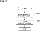
- a method of producing the poppet valve 32 includes forming the thermally sprayed layer 64 including a non-magnetic material on at least a part of the poppet end surface 58a or the contact surface 62a of the first valve casing 62 (thermal spraying step S10).
- the Vickers hardness Hv1 of the poppet end surface 58a and the Vickers hardness Hv2 of the thermally sprayed layer 64 have a relationship (Hv1-50Hv) ⁇ Hv2 ⁇ (Hv1+100Hv).
- the thermally sprayed layer 64 formed in the thermal spraying step S10 has a hardness substantially equivalent to that of the poppet end surface 58a and the contact surface 62a of the first valve casing 62, and thus it is possible to suppress aging of the thermally sprayed layer 64.
- the thermally sprayed layer 64 including a non-magnetic material is interposed between the poppet end surface 58a and the contact surface 62a, it is possible to reduce an attractive force due to magnetism remaining on the poppet 58 or the contact surface 62a on a closing operation of the poppet 58, which also improves the responsiveness of the poppet 58.
- an uneven portion forming step S12 is further performed. That is, as shown in FIGs. 5 and 6 , the uneven portion 92 is formed on the contact surface 62a or the poppet end surface 58a capable of making contact with the thermally sprayed layer 64, and the uneven portion 92 forms a space 's' between the thermally sprayed layer 64 and the contact surface 62a or the poppet end surface 58a.
- the space 's' being formed by the uneven portion 92 formed on the contact surface 62a or the poppet end surface 58a which repeatedly makes contact with or separates from the thermally sprayed layer 64, it is possible to suppress a differential pressure generated between the poppet end surface 58a and the valve-seat side surface on the valve-closing operation and the valve-opening operation of the poppet 58, and suppress deterioration of responsiveness in a valve operation due to the pressure differential.
- the thermally sprayed layer is formed on at least a part of the end surface of the poppet valve of the poppet 58 or the contact surface of the first valve casing by using a high velocity oxygen fuel (HVOF) spraying method.
- HVOF high velocity oxygen fuel
- the thermally sprayed layer 64 by using the HVOF method, it is possible to form a high density coating with a low porosity. Furthermore, it is possible to obtain a thermally sprayed layer that has a uniform hardness and undergoes less aging.
- the uneven portion 92 is formed by photo etching.
- the uneven portion 92 by photo etching, it is possible to form a micron-size complex uneven portion precisely as designed. Furthermore, it is possible to perform precise machine processing without forming burrs and strains, or causing hardening, etc.
- this poppet valve for a hydraulic machine or a hydraulic transmission of a renewable energy type power generating apparatus, for instance, it is possible to enhance the reliability of the renewable-energy type power generating apparatus.
Landscapes
- Engineering & Computer Science (AREA)
- General Engineering & Computer Science (AREA)
- Mechanical Engineering (AREA)
- Physics & Mathematics (AREA)
- Electromagnetism (AREA)
- Wind Motors (AREA)
- Magnetically Actuated Valves (AREA)
- Lift Valve (AREA)
- Details Of Valves (AREA)
Abstract
Description
- The present disclosure relates to a poppet valve, a hydraulic machine including the poppet valve, a hydraulic transmission including the hydraulic machine, a renewable-energy type power generating apparatus including the hydraulic mission, and a method of producing a poppet valve.
- A wind turbine power generating apparatus, which is a renewable-energy type power generating apparatus, may include a hydraulic transmission. A hydraulic transmission uses pressurized oil to convert rotational energy of a rotor that rotates in response to a wind force into mechanical energy, and thereby drives a generator.
- Patent Document 1, previously proposed by the present applicant, discloses a hydraulic transmission for a wind turbine power generating apparatus including a hydraulic pump configured to be driven by a rotor and pressurize working oil, and a hydraulic motor configured to drive a generator with high pressure oil supplied from the hydraulic pump through a high pressure oil flow passage. The hydraulic transmission is configured to return low pressure oil after driving the generator to the hydraulic pump via a low pressure oil flow passage. The hydraulic pump and the hydraulic motor each include a working chamber formed by a cylinder and a piston, and a poppet valve (solenoid valve) for controlling a communication state between the working chamber and the high pressure oil flow passage or the low pressure oil flow passage.
- Patent Document 1 discloses a diagnosis system in which, to prevent response delay of a magnetic poppet (valve body) caused by a fitting effect or residual magnetism between the poppet and a magnetic valve casing that makes contact with the poppet on a valve opening operation of the poppet, a plate member (position-restricting part) is disposed between the poppet and the valve casing. Accordingly, direct contact between the poppet and the valve casing is avoided to improve the responsiveness of the poppet, and damage such as wear and settling of the position-restricting part, for instance, can be detected from a change in response delay of the poppet.
- Furthermore, Patent Document 2 discloses providing an uneven portion on an end surface of a poppet (valve body) or a contact surface of a valve casing that makes contact with the poppet, to address deterioration of the responsiveness of the poppet valve due to a differential pressure between the front side and the back side of the poppet valve on a valve opening or closing operation of the poppet. With this uneven portion, a space is formed between the poppet and the contact surface. Accordingly, the differential pressure between the front side and the back side of the poppet is reduced, and thereby deterioration of the responsiveness of the poppet can be suppressed.
-
- Patent Document 1:
JP2017-151020A - Patent Document 2:
JP2017-008975A - As disclosed in Patent Document 1, in a case where a non-magnetic plate member (position-restricting part) is disposed between a poppet and a valve casing, which are both magnetic, aging such as wear and settling of the position-restricting part may cause response delay of the poppet. This is because, aging such as wear and settling of the position-restricting part increases separation resistance between the poppet and the valve casing. Furthermore, due to damage such as breakage of the position-restricting part, a fragment may enter the clearance between the poppet and the valve casing, and may cause juddering.
- Although Patent Document 2 discloses a diagnosis system capable of detecting damage in the position-restricting part, it does not disclose an approach for suppressing damage in the position-restricting part.
- In view of the above problem, an object of at least one embodiment is to suppress response delay of a poppet due to aging or damage in a position-restricting part.
- (1) A poppet valve according to at least one embodiment includes: a valve seat; a poppet disposed so as to face the valve seat; an actuator for driving the poppet; a first valve casing which houses the actuator and which includes a contact surface capable of making contact with an end surface of the poppet opposite to the valve seat, on a valve-closing operation of the poppet; and a thermally sprayed layer including a non-magnetic material, formed on at least a part of the end surface of the poppet or the contact surface of the first valve casing. A Vickers hardness Hv1 of the end surface of the poppet or the contact surface of the first valve casing and a Vickers hardness Hv2 of the thermally sprayed layer satisfy a relationship (Hv1-50Hv)≤Hv2≤(Hv1+100Hv).
- In the present embodiment, "an end surface of the poppet opposite to the valve seat" refers to an end surface that is further from the valve seat, of the two surfaces of the poppet in the moving direction of the poppet.
- In the above configuration (1), the end surface of the poppet and the contact surface of the first valve casing make contact with each other via the thermally sprayed layer when the poppet valve is in a valve open state, and separate from each other by a valve-closing operation of the poppet. Thus, the thermally sprayed layer often makes contact with and separates from the contact surface of the first valve casing or the poppet end surface, and thus in an environment in which aging such as wear and settling is likely to occur.
- With the above configuration (1), the thermally sprayed layer, the poppet end surface and the contact surface of the first valve casing satisfy the above relationship of hardness, and thus have a substantially equivalent hardness. Thus, it is possible to suppress aging of the thermally sprayed layer even in the above environment. Thus, it is possible to suppress response delay of the poppet due to aging of the thermally sprayed layer. Furthermore, it is possible to suppress an event in which, due to damage to the thermally sprayed layer, a fragment enters the clearance between the poppet and the valve casing and causes juddering.
- Furthermore, the thermally sprayed layer including a non-magnetic material is interposed between the poppet end surface and the contact surface of the first valve casing, and thus it is possible to reduce the attractive force due to magnetism remaining on the poppet or the first valve casing on a closing operation of the poppet, which also improves the responsiveness of the poppet.
- (2) In an embodiment, in the above configuration (1), a base material of the non-magnetic material of the thermally sprayed layer has a Vickers harness of not less than 450.
With the above configuration (2), with the above thermally sprayed layer including a non-magnetic base material that has a high Vickers hardness Hv of not less than 450, it is possible to suppress aging of the thermally sprayed layer, which makes it possible to suppress response delay of the poppet due to aging of the thermally sprayed layer. - (3) In an embodiment, in the above configuration (1), a Rockwell hardness of the thermally sprayed layer after formation of a coating is not less than 45.
With the above configuration (3), with the thermally sprayed layer after forming a coating having a high Rockwell hardness HRC of not less than 45, it is possible to suppress aging of the thermally sprayed layer, which makes it possible to suppress response delay of the poppet due to aging of the thermally sprayed layer. - (4) In some embodiments, in any one of the above configurations (1) to (3), the thermally sprayed layer has a layer thickness of not less than 1mm.
With the above configuration (4), with the thermally sprayed layer having a layer thickness of not less than 1mm, it is possible to maintain the strength of the thermally sprayed layer and thereby suppress aging of the thermally sprayed layer, which makes it possible to suppress response delay of the poppet due to aging of the thermally sprayed layer. - (5) In an embodiment, in any one of the above configurations (1) to (4), the thermally sprayed layer includes a cobalt-chromium alloy also containing tungsten, a nickel alloy, or a tungsten alloy.
A cobalt-chromium alloy also containing tungsten (e.g. Stellite®) has a Vickers hardness of 500 to 650Hv, and a nickel alloy and a tungsten alloy have a Vickers hardness of 600 to 700Hv, each having a high hardness. Thus, with the thermally sprayed layer including one of the above materials, it is possible to suppress aging of the thermally sprayed layer, which makes it possible to suppress response delay of the poppet due to aging of the thermally sprayed layer. - (6) In an embodiment, in any one of the above configurations (1) to (5), the poppet valve further includes a biasing member for biasing the poppet toward the valve seat. The poppet and the first valve casing are both at least partially formed by a magnetic element, and the actuator includes a solenoid configured to, in an excited state, generate an electromagnetic force which attracts the poppet toward the first valve casing, against a biasing force of the biasing member.
In a case where the poppet valve is a normally-closed type solenoid valve as described in the above (6), the responsiveness of the valve-closing operation may decrease due to an attractive force generated by the residual magnetism of the valve casing, even if power supply to the solenoid is stopped on a valve-closing operation.
Thus, in a case where the above configuration (1) is applied to a normally-closed type solenoid valve, by forming the thermally sprayed layer between the poppet end surface in the valve-open position and the contact surface (magnetic-attractive surface) of the first valve casing, it is possible to reduce an attractive force due to residual magnetism, and to improve the responsiveness of the valve operation (e.g. the valve-closing response speed). - (7) In an embodiment, in any one of the above configurations (1) to (6), the contact surface of the first valve casing or the end surface of the poppet capable of making contact with the thermally sprayed layer includes an uneven portion configured to form a space between the thermally sprayed layer and the contact surface of the first valve casing or the end surface of the poppet.
- If the thermally sprayed layer makes close surface-contact with the contact surface of the first valve casing or the poppet end surface in a valve-opened state, when the thermally sprayed layer separates from the contact surface of the first valve casing or the poppet end surface on a valve closing operation, brief expansion occurs in the space between the thermally sprayed layer and the contact surface of the first valve casing or the poppet end surface, which reduces the pressure and generates a pressure differential between the thermally sprayed layer and the valve-seat side surface of the poppet. This pressure differential leads to deterioration of responsiveness in a valve-closing operation. Similarly, on a valve-opening operation, when the end surface of the poppet approaches the contact surface of the first valve casing, brief compression may occur in the space between the above surfaces to increase the pressure, and the responsiveness of the valve-opening operation may deteriorate due to a pressure differential created between the end surface of the poppet and the valve-seat side surface.
- With the above configuration (7), it is possible to suppress deterioration of responsiveness of the valve operation due to a pressure differential caused between the poppet end surface and the valve-seat side surface when the poppet is activated. Specifically, when the thermally sprayed layer moves away from the poppet end surface or the contact surface of the first valve casing on a valve-closing operation, it is possible to suppress a rapid pressure decrease in the gap between the thermally sprayed layer and the poppet end surface or the contact surface of the first valve casing thanks to the presence of the space, which makes it possible to suppress deterioration of responsiveness in a valve-closing operation due to a pressure differential between the poppet end surface and the valve-seat side surface. Similarly, on a valve-opening operation, when the thermally sprayed layer moves toward the poppet end surface or the contact surface of the first valve casing, it is possible to suppress a rapid pressure increase in the gap between the thermally sprayed layer and the poppet end surface or the contact surface of the first valve casing thanks to the presence of the space, which makes it possible to suppress deterioration of responsiveness of a valve-opening operation due to a pressure differential between the poppet end surface and the valve-seat side surface.
- Further, in a case where the thermally sprayed layer is in contact with the poppet end surface or the contact surface of the first valve casing, and the fluid around the poppet is capable of flowing into the space, it is possible to reduce a pressure differential between the poppet end surface and the valve-seat side surface even further, and improve the responsiveness of the valve operation more effectively.
- Further, since it is possible to reduce the contact area between the thermally sprayed layer and the poppet end surface or the contact surface of the first valve casing with the space, it is possible to achieve a structure such that it is difficult for the thermally sprayed layer to be in close contact with the poppet end surface or the contact surface of the first valve casing. Accordingly, it is possible to suppress deterioration of responsiveness in a valve-closing operation.
- (8) In an embodiment, in the above configuration (7), the uneven portion is formed by a plurality of first grooves and a plurality of second grooves intersecting with the first grooves, so as to have a mesh shape.
With the above configuration (8), it is possible to form myriad minute uneven sections easily or to form a uniform uneven section over a wide range. Thus, it is possible to securely reduce a pressure differential generated between the end surface of the poppet and the valve-seat side surface on a valve operation and to improve the responsiveness of the valve operation effectively. Further, it is possible to achieve a structure such that the unevenness forming surface can hardly be damaged by collision between the thermally sprayed layer and the poppet end surface or the contact surface of the first valve casing. - (9) In an embodiment, in the above configuration (8), an arithmetic average roughness Ra of a surface of a protruding portion constituting the uneven portion is not greater than 0.05.
With the above configuration (9), in a case where the protruding portion constitutes the uneven portion formed on the contact surface of the first valve casing or the poppet end surface which repeatedly makes contact with or separates from the thermally sprayed layer, with the protruding portion having a surface whose arithmetic average roughness Ra is not greater than 0.05, which means that the surface is smooth, it is possible to suppress aging such as wear and settling of the thermally sprayed layer. - (10) In an embodiment, in the above configuration (8) or (9), a protruding portion constituting the uneven portion has a rectangular outer shape in a view along a height direction of the protruding portion, and a length L of a side of the rectangular and a width of the first grooves and the second grooves satisfy a relationship 0.7W≤L≤1.3W.
With the above configuration (10), the length L of a side of the rectangular and the width W of the first grooves and the second grooves satisfy a relationship 0.7W≤L≤1.3W, and thus it is possible to suppress slant contact with the surface of the thermally sprayed layer, which makes it possible to suppress aging such as wear and settling of the thermally sprayed layer. - (11) In an embodiment, in the above configuration (7), the uneven portion is formed to have a dimple shape.
With the above configuration (11), the uneven portion having a dimple shape is formed on the contact surface of the first valve casing or the poppet end surface which repeatedly makes contact with or separates from the thermally sprayed layer, and thereby it is possible to suppress slant contact with the surface of the thermally sprayed layer, which makes it possible to suppress aging such as wear and settling of the thermally sprayed layer, as well as facilitate machining of the uneven portion to form the uneven portion at low cost. - (12) In an embodiment, in any one of the above configurations (7) to (11), the poppet valve is configured to be openable and closeable so as to switch a pressure inside a working chamber of a hydraulic machine, and the uneven portion is formed by a drain groove for working oil of the hydraulic machine, the drain groove being disposed on at least one of the end surface of the poppet or the contact surface of the first valve casing.
With the above configuration (12), when the thermally sprayed layer moves in a direction away from the contact surface of the first valve casing or the poppet end surface on a valve closing operation, the pressure of the surface of the thermally sprayed layer decreases. At this time, working oil of the hydraulic machine is supplied to the drain groove formed by the uneven portion, and thus the pressure decrease of the surface of the thermally sprayed layer is suppressed. Accordingly, it is possible to suppress a pressure differential between the poppet end surface and the valve-seat side surface, and thus it is possible to suppress response delay of the poppet. - (13) In an embodiment, in any one of the above configurations (1) to (6), the poppet valve further includes a gap forming portion for forming a gap between the thermally sprayed layer and the contact surface of the first valve casing or between the thermally sprayed layer and the end surface of the poppet, when the thermally sprayed layer is in a position closest to the contact surface of the first valve casing or the end surface of the poppet.
With the above configuration (13), the position of the poppet is restricted by the gap forming portion when the thermally sprayed layer is in a position closest to the contact surface of the first valve casing or the poppet end surface, and thereby a gap is formed between the thermally sprayed layer and the contact surface of the first valve casing or the poppet end surface. Thus, compared to a case in which the thermally sprayed layer makes direct contact with the contact surface of the first valve casing or the poppet end surface, it is possible to suppress aging of the thermally sprayed layer. Accordingly, it is possible to suppress response delay of the poppet due to aging of the thermally sprayed layer.
Furthermore, even if aging of the thermally sprayed layer occurs, the thermally sprayed layer does not make direct contact with the poppet end surface or the contact surface of the first valve casing on a valve-opening operation of the poppet, and thus aging of the thermally sprayed layer does not advance further. - (14) In an embodiment, in the above configuration (13), the gap forming portion includes: a first diameter increasing portion formed on the end surface of the poppet and having a diameter increasing outward with respect to a radial direction of the end surface; and a stopper portion disposed on a radially outer side of the contact surface of the first valve casing and configured to be capable of stopping the poppet by making contact with the first diameter increasing portion when the thermally sprayed layer is in a position closest to the contact surface of the first valve casing or the end surface of the poppet.
With the above configuration (13), the stopper portion makes contact with the first diameter increasing portion and interlocks with the poppet when the thermally sprayed layer is in a position closest to the contact surface of the first valve casing or the poppet end surface, and thereby it is possible to prevent direct contact between the thermally sprayed layer and the contact surface of the first valve casing or the poppet end surface. Furthermore, the first diameter increasing portion is formed on the poppet end surface, and thus it is possible to set a position relative to the poppet end surface with respect to the valve moving direction, which makes it possible to set the position of the first diameter increasing portion. - (15) In an embodiment, in the above configuration (13), the poppet valve further includes a second valve casing forming the valve seat; and an annular spacer disposed on a radially outer side of the poppet, between the first valve casing and the second valve casing, and including at least one communication flow passage formed thereon so as to bring an inner space housing the poppet and an outer space into communication. The gap forming portion includes a step portion which is formed on an outer peripheral surface of the poppet and which is capable of interlocking with the annular spacer when the thermally sprayed layer is in a position closest to the contact surface of the first valve casing or the end surface of the poppet.
With the above configuration (15), when the thermally sprayed layer is in a position closest to the contact surface of the first valve casing or the poppet end surface, the step portion interlocks with the annular spacer, and thus it is possible to simply prevent direct contact between the thermally sprayed layer and the contact surface of the first valve casing or the poppet end surface. - (16) In an embodiment, in the above configuration (13), the poppet valve further includes a second valve casing forming the valve seat; and an annular spacer disposed on a radially outer side of the poppet, between the first valve casing and the second valve casing, and including at least one communication flow passage formed thereon so as to bring an inner space housing the poppet and an outer space into communication. The poppet has a cone shape having a diameter gradually increasing toward the valve seat, and the gap forming portion is configured such that an outer peripheral surface of the poppet makes contact with the annular spacer when the thermally sprayed layer is in a position closest to the contact surface of the first valve casing or the end surface of the poppet.
With the above configuration (16), when the thermally sprayed layer is in contact with the contact surface of the first valve casing or the poppet end surface, the outer peripheral surface of the poppet makes contact with the annular spacer and stops the valve-opening operation. Accordingly, it is possible to simply prevent direct contact between the thermally sprayed layer and the poppet end surface or the contact surface of the first valve casing. - (17) In an embodiment, in the above configuration (13), the poppet valve further includes: a rod which is loosely fit into a through hole formed on the poppet along a moving direction of the poppet, the rod being configured to guide the poppet to a valve closed position and a valve open position; and a second diameter increasing portion disposed on the rod and configured to be capable of stopping the poppet when the thermally sprayed layer is in a position closest to the contact surface of the first valve casing or the end surface of the poppet.
With the above configuration (17), when the thermally sprayed layer is in a position closest to the contact surface of the first valve casing or the poppet end surface, the second diameter increasing portion interlocks with the poppet and stops the movement of the poppet, and thus it is possible to simply prevent direct contact between the thermally sprayed layer and the contact surface of the first valve casing or the poppet end surface. - (18) A hydraulic machine according to at least one embodiment of the present invention includes: a cylinder; a piston which reciprocates inside the cylinder; and the poppet valve according to any one of claims 1 to 17 configured to control a communication state between an external flow passage and a working chamber formed by the cylinder and the piston.
The hydraulic machine having the above configuration (18) includes the poppet valve with an excellent responsiveness as described above, and thus it is possible to improve the reliability of the hydraulic machine. - (19) A hydraulic transmission according to at least one embodiment of the present invention includes: a hydraulic pump for generating a high pressure oil; a hydraulic motor configured to be driven by the high pressure oil supplied from the hydraulic pump; a high pressure oil flow passage for supplying the high pressure oil from the hydraulic pump to the hydraulic motor; and a low pressure oil flow passage for returning low pressure oil discharged from the hydraulic motor to the hydraulic pump. At least one of the hydraulic pump or the hydraulic motor comprises the hydraulic machine according to the above (18).
The hydraulic transmission having the above configuration (19) produces high pressure oil with the hydraulic pump, and drives the hydraulic motor with the high pressure oil. At least one of the hydraulic pump or the hydraulic motor includes a hydraulic machine having a high responsiveness, which makes it possible to improve reliability of the hydraulic transmission.
Generally, the hydraulic motor for driving a generator is required to operate with a high reliability under harsh operational conditions of approximately 1000rpm, for instance. Thus, as described above, by providing the poppet valve with the above responsiveness, it is possible to secure a high reliability which can meet the requirement of the hydraulic motor for driving a generator. - (20) A renewable-energy type power generating apparatus according to at least one embodiment includes: a rotor configured to receive renewable energy and rotate; the hydraulic transmission according to the above (19); a generator configured to be driven by the hydraulic motor. The hydraulic pump is configured to be driven by the rotor and produce the high pressure oil, and the hydraulic motor is configured to drive the generator with the high pressure oil supplied from the hydraulic pump.
With the above configuration (20), at least one of the hydraulic pump or the hydraulic motor constituting the hydraulic transmission includes the hydraulic machine including the poppet valve having a high reliability, and thus the wind turbine power generating apparatus can be operated stably as a renewable energy type power generating apparatus. - (21) A method of producing a poppet valve which comprises: a valve seat; a poppet disposed so as to face the valve seat; an actuator for driving the poppet; and a first valve casing which houses the actuator and which includes a contact surface capable of making contact with an end surface of the poppet opposite to the valve seat, according to at least one embodiment of the present invention, includes: a thermal spraying step of forming a thermally sprayed layer including a non-magnetic material on at least a part of the end surface of the poppet valve or the contact surface of the valve casing. A Vickers hardness Hv1 of the end surface of the poppet and a Vickers hardness Hv2 of the thermally sprayed layer satisfy a relationship (Hv1-50Hv)≤Hv2≤(Hv1+100Hv).
According to the above method (21), a thermally sprayed layer including a non-magnetic material is formed on at least a part of the end surface of the poppet or the contact surface of the first valve casing. The thermally sprayed layer, the poppet end surface and the contact surface of the first valve casing satisfy the above relationship of hardness, and thus have a substantially equivalent hardness. Thus, it is possible to suppress aging of the thermally sprayed layer even in the above environment. Thus, it is possible to suppress response delay of the poppet due to aging of the thermally sprayed layer. Furthermore, it is possible to suppress an event in which, due to damage to the thermally sprayed layer, a fragment enters the clearance between the poppet and the valve casing and causes juddering.
Furthermore, the thermally sprayed layer including a non-magnetic material is interposed between the poppet end surface and the contact surface of the first valve casing, and thus it is possible to reduce an attractive force due to magnetism remaining on the poppet or the valve casing on a closing operation of the poppet, which also improves the responsiveness of the poppet. - (22) In an embodiment, in the above method (21), the method further includes a step of forming an uneven portion on the contact surface of the first valve casing or the end surface of the poppet valve capable of making contact with the thermally sprayed layer, and forming a space between the thermally sprayed layer and the contact surface of the first valve casing or the end surface of the poppet valve with the uneven portion.
According to the above method (22), with the space being formed by the uneven portion formed on the contact surface of the first valve casing or the poppet end surface which repeatedly makes contact with or separates from the thermally sprayed layer, it is possible to suppress a differential pressure generated between the poppet end surface and the valve-seat side surface on a valve-closing operation and a valve-opening operation of the poppet, and suppress deterioration of responsiveness in a valve operation due to the pressure differential. - (23) In an embodiment, in the above method (21) or (22), the thermal spraying step includes forming the thermal spraying layer on at least a part of the end surface of the poppet or the contact surface of the first valve casing by high velocity oxygen fuel (HVOF) combustion spraying.
According to the above method (22), by forming the thermally sprayed layer by using the HVOF combustion spraying, it is possible to form a high density coating with a low porosity. Furthermore, it is possible to obtain a thermally sprayed layer which has a uniform hardness and which undergoes less aging. - (24) In an embodiment, in the above method (22), the uneven portion forming step includes forming the uneven portion by photo etching.
- According to the above method (2), by forming the uneven portion by photo etching, it is possible to form a micron-size complex uneven portion precisely as designed. Furthermore, it is possible to perform precise machine processing without forming burrs and strains, or causing hardening, etc.
- In some embodiments, it is possible to suppress response delay and juddering of a poppet due to aging and damage such as wear and settling of the thermally sprayed layer formed on the poppet end surface or the contact surface of the first valve casing to be in contact with the poppet end surface.
-
-
FIG. 1 is an overall configuration diagram of a wind turbine power generating apparatus according to an embodiment. -
FIG. 2 is a schematic configuration diagram of a hydraulic machine according to an embodiment. -
FIG. 3 is a schematic cross-sectional configuration diagram of a high pressure valve and a low pressure valve according to an embodiment. -
FIG. 4 is a vertical cross-sectional configuration view of a poppet valve according to an embodiment. -
FIG. 5 is a vertical cross-sectional configuration view of a poppet valve according to an embodiment. -
FIG. 6 is a partial enlarged view ofFIG. 5 . -
FIG. 7 is a planar view of a poppet according to an embodiment. -
FIG. 8A is a planar configuration diagram of an uneven portion according to an embodiment. -
FIG. 8B is a cross-sectional configuration diagram of an uneven portion according to an embodiment. -
FIG. 9A is a planar configuration diagram of an uneven portion according to an embodiment. -
FIG. 9B is a cross-sectional configuration diagram of an uneven portion according to an embodiment. -
FIG. 10 is a vertical cross-sectional configuration view of a poppet valve according to an embodiment. -
FIG. 11 is a vertical cross-sectional configuration view of a poppet valve according to an embodiment. -
FIG. 12 is a vertical cross-sectional configuration view of a poppet valve according to an embodiment. -
FIG. 13 is a flowchart of a method of producing a poppet valve according to an embodiment. - Embodiments of the present invention will now be described in detail with reference to the accompanying drawings. It is intended, however, that unless particularly specified, dimensions, materials, shapes, relative positions and the like of components described in the embodiments shall be interpreted as illustrative only and not intended to limit the scope of the present invention.
- For instance, an expression of relative or absolute arrangement such as "in a direction", "along a direction", "parallel", "orthogonal", "centered", "concentric" and "coaxial" shall not be construed as indicating only the arrangement in a strict literal sense, but also includes a state where the arrangement is relatively displaced by a tolerance, or by an angle or a distance whereby it is possible to achieve the same function.
- For instance, an expression of an equal state such as "same" "equal" and "uniform" shall not be construed as indicating only the state in which the feature is strictly equal, but also includes a state in which there is a tolerance or a difference that can still achieve the same function.
- Further, for instance, an expression of a shape such as a rectangular shape or a cylindrical shape shall not be construed as only the geometrically strict shape, but also includes a shape with unevenness or chamfered corners within the range in which the same effect can be achieved.
- On the other hand, an expression such as "comprise", "include", "have", "contain" and "constitute" are not intended to be exclusive of other components.
-
FIG. 1 is a schematic diagram of a wind turbinepower generating apparatus 10 according to an embodiment. As illustrated in the drawing, the wind turbinepower generating apparatus 10 includes arotor 12 configured to rotate in response to wind, which is a renewable energy, ahydraulic transmission 14 for transmitting rotation of therotor 12, and agenerator 16 for generating electric power. - The
rotor 12 includes at least oneblade 18, and ahub 20 to which the at least oneblade 18 is mounted. - The
hydraulic transmission 14 includes ahydraulic pump 24 coupled to therotor 12 via arotational shaft 22 and configured to generate high pressure oil, ahydraulic motor 26 configured to be driven by the high pressure oil supplied from thehydraulic pump 24, a high pressureoil flow passage 28 for supplying high pressure oil from thehydraulic pump 24 to thehydraulic motor 26, and a low pressureoil flow passage 30 for returning low pressure oil discharged from thehydraulic motor 26 to thehydraulic pump 24. - The
generator 16 is coupled to thehydraulic motor 26 via an output shaft of thehydraulic motor 26. For instance, thegenerator 16 is a synchronous generator driven by thehydraulic motor 26, and is connected to a utility grid. - In an embodiment, the
hydraulic transmission 14 and thegenerator 16 are disposed inside anacelle 29 disposed on an upper part of thetower 31. - The rotational energy of the
rotor 12 is inputted into thegenerator 16 via thehydraulic transmission 14 including thehydraulic pump 24 and thehydraulic motor 26, and electric power is generated by thegenerator 16. - When the at least one
blade 18 receives wind, theentire rotor 12 rotates due to the power of the wind, so that thehydraulic pump 24 is driven by therotor 12 to pressurize working oil, thereby producing high pressure working oil (pressurized oil). The pressurized oil produced by thehydraulic pump 24 is supplied to thehydraulic motor 26 via the high pressureoil flow passage 28, and drives thehydraulic motor 26. Electric power is generated by thegenerator 16 connected to thehydraulic motor 26 via the output shaft. The low pressure working oil having performed work in thehydraulic motor 26 returns to thehydraulic pump 24 via the low pressureoil flow passage 30. - The
hydraulic pump 24 and thehydraulic motor 26 may be of a variable-displacement type whereby the displacement is adjustable. - In some embodiments, at least one of the above described
hydraulic pump 24 or thehydraulic motor 26 is ahydraulic machine 40 described below. -
FIG. 2 is a schematic configuration diagram of ahydraulic machine 40 according to an embodiment. As a basic configuration, thehydraulic machine 40 includes at least onecylinder 42 and a piston which reciprocates inside thecylinder 42. Thecylinder 42 and thepiston 44 form a workingchamber 46. The workingchamber 46 is in communication with a high pressureoil flow passage 28 and a low pressure oil flow passage 30 (external passage). Ahigh pressure valve 32 is disposed in the high pressureoil flow passage 28, and alow pressure valve 34 is disposed in the low pressureoil flow passage 30. As thehigh pressure valve 32 and thelow pressure valve 34 open and close, the communication state between the workingchamber 46 and the high pressureoil flow passage 28 and the low pressureoil flow passage 30 is controlled. - The
hydraulic machine 40 further includes arotational shaft 48, and a cam 50 (conversion mechanism) for converting rotational motion of therotational shaft 48 and reciprocal motion of thepiston 44, or vice versa. Thecam 50 is an eccentric cam disposed eccentrically from the axial center O of therotational shaft 48. While thepiston 44 performs a set of upward and downward movement, therotational shaft 48 to which thecam 50 is mounted performs one revolution. - In an embodiment, as shown in
FIG. 2 , a plurality ofcylinders 42 and a plurality ofpistons 44 are disposed along the circumferential direction of thehydraulic machine 40. - In the
hydraulic machine 40 depicted inFIG. 2 , thehigh pressure valves 32 and thelow pressure valves 34 are controlled in accordance with reciprocal motion of thepistons 44, so that a pressure of each workingchamber 46 changes periodically in accordance with the reciprocal motion of thepistons 44. Now, configuration of thehigh pressure valve 32 and thelow pressure valve 34 of thehydraulic machine 40 will be described, along with a periodical change of the working chamber pressure caused by opening-and-closing control on the valves. -
FIG. 3 is a schematic cross-sectional view of a configuration of thehigh pressure valve 32 and thelow pressure valve 34. In the example depicted inFIG. 3 , both of thehigh pressure valve 32 and thelow pressure valve 34 are solenoid valves, andFIG. 3 is a view of a situation in which thehigh pressure valve 32 is closed and thelow pressure valve 34 is open. In some embodiments, as depicted inFIG. 3 , thehigh pressure valve 32, thelow pressure valve 34, and acasing 43 housing the valves may be unitized and configured as avalve unit 41. - The
high pressure valve 32 illustrated inFIG. 3 includes anactuator 60 for moving thevalve body 58 between a valve-open position and a valve-closed position, a biasingmember 66, and avalve seat 56. Thehigh pressure valve 32 is a poppet solenoid valve of a normally-closed type, with thevalve seat 56 disposed on a side adjacent to the workingchamber 46 with respect to thevalve body 58. Thehigh pressure valve 32 is capable of switching the communication state between the workingchamber 46 and the high pressure oil flow passage 28 (seeFIG. 2 ) through an opening-and-closing operation of thevalve body 58. - In an embodiment, the
actuator 60 is a solenoid coil, and the biasingmember 66 is a spring. Thevalve body 58 includes a valve body having a poppet shape. - The
low pressure valve 34 illustrated inFIG. 3 includes amovable unit 84 including avalve body 80 and anarmature 82, asolenoid coil 86, aspring 88, and avalve seat 90. Thelow pressure valve 34 is a poppet solenoid valve (poppet valve) of normally-open type, with thevalve body 80 disposed on the side adjacent to the workingchamber 46 with respect to thevalve seat 90. Thelow pressure valve 34 is capable of switching the communication state between the workingchamber 46 and the low pressure oil flow passage 30 (seeFIG. 2 ) by movement of themovable unit 84 caused by an electromagnetic force of thesolenoid coil 86 or a biasing force of thespring 88. - The
high pressure valve 32 and thelow pressure valve 34 are controlled to open and close with control signals (open-close command) sent from avalve control part 76. In some embodiments, thevalve control part 76 provides thehigh pressure valve 32 and thelow pressure valve 34 with control signals for the open-close command. - In a case where the
hydraulic machine 40 is applied to thehydraulic pump 24, therotational shaft 48 is connected to therotational shaft 22 of therotor 12. As therotational shaft 22 rotates, therotational shaft 48 rotates. In response to rotation of therotational shaft 48, thepiston 44 reciprocates inside the workingchamber 46 and thereby high pressure oil is generated. The generated high pressure oil is supplied to thehydraulic motor 26 via the high pressureoil flow passage 28. - In a case where the
hydraulic machine 40 is applied to thehydraulic motor 26, therotational shaft 48 is coupled to thegenerator 16. Therotational shaft 48 is rotated by high pressure oil supplied to the plurality of workingchambers 46 in sequence from the high pressureoil flow passage 28. In response to rotation of therotational shaft 48, thegenerator 16 generates electric power. - In an embodiment, as shown in
FIG. 2 , thehigh pressure valves 32 are disposed in a highpressure communication line 52 between the high pressureoil flow passage 28 and the respective workingchambers 46, and configured to be capable of switching the communication state between the respective workingchambers 46 and the high pressureoil flow passage 28. Thelow pressure valves 34 are disposed in a lowpressure communication line 54 between the low pressureoil flow passage 30 and the respective workingchambers 46, and configured to be capable of switching the communication state between the respective workingchambers 46 and the low pressureoil flow passage 30. - Next, the configuration of some poppet valves used as
high pressure valves 32 will be described with reference toFIGs. 4 to 12 . The poppet valves may be used aslow pressure valves 34. - As shown in
FIGs. 4 to 12 , the poppet valve 32 (32A, 32B, 32C, 32D, 32E) according to some embodiments includes a poppet (valve body) 58 disposed so as to face thevalve seat 56, and is configured to be movable by theactuator 60. Theactuator 60 is housed inside thefirst valve casing 62. Thefirst valve casing 62 includes acontact surface 62a capable of making contact with anend surface 58a of thepoppet 58, disposed opposite to thevalve seat 56, on an valve-opening operation of thepoppet 58, via a thermally sprayedlayer 64. The thermally sprayedlayer 64 includes a non-magnetic material and is formed on at least a part of the end surface 48a of thepoppet 58 or thecontact surface 62a of thefirst valve casing 62. The Vickers hardness Hv1 of theend surface 58a of thepoppet 58 or thecontact surface 62a of thefirst valve casing 62 and the Vickers hardness Hv2 of the thermally sprayedlayer 64 have the following relationship (1): (Hv1-50Hv)≤Hv2≤(Hv1+100Hv). - With the above configuration, to satisfy the hardness condition of the above expression (1), the hardness of the thermally sprayed
layer 64 is substantially equivalent to the hardness of thepoppet end surface 58a or thecontact surface 62a. As a result, even if the thermally sprayedlayer 64 repeatedly makes contact with or separates from thepoppet end surface 58a or thecontact surface 62a, it is possible to suppress aging (wear, fitting, settling, etc.) of the thermally sprayedlayer 64, and thus it is possible to suppress the response delay of thepoppet 58 due to aging of the thermally sprayedlayer 64. That is, on occurrence of a valve-closing operation from a valve open state where thepoppet end surface 58a is in contact with thecontact surface 62a via the thermally sprayedlayer 64, it is possible to suppress a decrease in the valve-closing response speed due to an increase of separation resistance due to aging of the thermally sprayedlayer 64. Furthermore, it is possible to prevent an event in which, due to damage to the thermally sprayedlayer 64, a fragment enters the clearance between thepoppet 58 and thecontact surface 62a and causes juddering. - Furthermore, the thermally sprayed
layer 64 including a non-magnetic material is interposed between thepoppet end surface 58a and thecontact surface 62a, and thus it is possible to reduce an attractive force due to magnetism remaining on thepoppet 58 or thefirst valve casing 62 on a closing operation of thepoppet 58, which also improves the responsiveness of thepoppet 58. - Furthermore, the thermally sprayed
layer 64 may be formed on thepoppet end surface 58a, or on thecontact surface 62a of thefirst valve casing 62. - By reducing the area of the thermally sprayed
layer 64 and forming the thermally sprayedlayer 64 partially on thepoppet end surface 58a or thecontact surface 62a, it is possible to reduce the fitting effect and the separation resistance of the thermally sprayedlayer 64 with the poppet end surface 48a or thecontact surface 62a. Thus, by reducing the area of the thermally sprayedlayer 64 without impairing the original function of the thermally sprayedlayer 64, it is also possible to improve the response delay of thepoppet 58. - In an embodiment, as shown in
FIG. 4 , the biasingmember 66 is further provided, to bias thepoppet 58 toward thevalve seat 56. Thepoppet 58 and thefirst valve casing 62 include at least a portion made from a magnetic element. Theactuator 60 includes a solenoid configured to generate an electromagnetic force that attracts thepoppet 58 toward thefirst valve casing 62 against the biasing force applied by the biasingmember 66 in an excited state. - In this embodiment, the
poppet valve 32 is a normally-closed type solenoid valve, and the response speed of the valve-closing operation may decrease due to an attractive force generated by the residual magnetism of thefirst valve casing 62, even if power supply to the solenoid is stopped on a valve-closing operation. - Thus, by forming the thermally sprayed
layer 64 between thepoppet end surface 58a in the valve-open position and thecontact surface 62a (magnetic-attractive surface), it is possible to reduce an attractive force due to residual magnetism, and to improve the responsiveness of the valve operation (e.g. valve-closing response speed). - In an embodiment, as shown in
FIG. 4 , the second valve casing 68 forming thevalve seat 56 is provided, and anannular spacer 70 is disposed on the radially outer side of thepoppet 58, between thefirst valve casing 62 and thesecond valve casing 68. Theannular spacer 70 includes at least one communication flow passages f1 and f2 formed thereon, to bring the interior space housing thepoppet 58 and the exterior space into communication. As thepoppet 58 is disposed radially inside theannular spacer 70, it is possible to secure a suitable space to allow movement of thepoppet 58. Further, with the communication flow passages f1 and f2 formed on theannular spacer 70, an inner flow passage is formed to bring the interior space and the exterior space of theannular spacer 70 into communication, and thus it is possible to form a smooth flow of a fluid between the communication flow passage f3 to be opened and closed by thepoppet 58 and an external flow passage (e.g. the highpressure communication line 52 illustrated inFIG. 3 ) of thepoppet valve 32. - In an embodiment, the
poppet 58 includes at least onecommunication window 59 formed thereon, which is in communication with the communication flow passage f1, in the circumferential direction. The communication flow passage f3 is formed inside thesecond valve casing 68. The communication flow passages f1 and f2, and the communication flow passage f3 are brought into communication with one another by a valve-opening operation of thepoppet 58, and the communication therebetween is shut off by a valve-closing operation of thepoppet 58. - In an embodiment, as shown in
FIG. 3 , the communication flow passages f1 and f2 are in communication with the high pressureoil flow passage 28, and the communication flow passage f3 is in communication with the workingchamber 46. - In an embodiment, as shown in
FIG. 4 , anannular member 72 is disposed between thefirst valve casing 62 and theannular spacer 70. - In an embodiment, the
poppet 58 has a rod throughhole 58b formed along the operation direction of thepoppet 58. Arod 74 is loosely fit into the rod throughhole 58b, and guides thepoppet 58 to a valve-closed position or a valve-open position. - In an embodiment, the
poppet end surface 58a and thecontact surface 62a are formed to have an annular shape centered at the rod throughhole 58b, and the thermally sprayedlayer 64 is formed in an annular shape in at least a part of thepoppet end surface 58a or thecontact surface 62a. - In an embodiment, a seat surface 75 (to be in contact with the valve seat 56) protruding toward the valve seat is formed on a valve-seat side surface of the
poppet 58. Theseat surface 75 is formed to have a double concentric shape, and makes contact with thevalve seat 56 formed on thefirst valve casing 62 on a valve-closing operation of thepoppet 58. Accordingly, it is possible to prevent leakage of working oil when the valve is closed. - In an embodiment, under the hardness condition of the above expression (1), the base material of the non-magnetic material of the thermally sprayed
layer 64 includes a material with a Vickers hardness of not less than 450. - According to this embodiment, with the thermally sprayed
layer 64 having a high hardness, it is possible to suppress aging of the thermally sprayedlayer 64, which makes it possible to suppress response delay of thepoppet 58 due to aging of the thermally sprayedlayer 64. - In an embodiment, under the hardness condition of the above expression (1), the Rockwell hardness HRC of the thermally sprayed
layer 64 after forming a coating is not less than 45. - According to this embodiment, with the thermally sprayed
layer 64 after forming a coating having a high hardness, it is possible to suppress aging of the thermally sprayedlayer 64, which makes it possible to suppress response delay of thepoppet 58 due to aging of the thermally sprayedlayer 64. - In an embodiment, the layer thickness of the thermally sprayed
layer 64 is not less than 1mm. - According to this embodiment, with the thermally sprayed
layer 64 having a layer thickness of not less than 1mm, it is possible to maintain the strength of the thermally sprayedlayer 64 and thereby suppress aging of the thermally sprayedlayer 64, which makes it possible to suppress response delay of the poppet due to aging of the thermally sprayedlayer 64. - Furthermore, preferably, the layer thickness of the thermally sprayed
layer 64 may be not less than 4mm. Accordingly, it is possible to suppress aging of the thermally sprayedlayer 64 even more effectively, which makes it possible to suppress response delay of the poppet due to aging of the thermally sprayedlayer 64 effectively. - In an embodiment, the thermally sprayed
layer 64 includes a cobalt-chromium alloy also containing tungsten, a nickel alloy, or a tungsten alloy. - A cobalt-chromium alloy also containing tungsten (e.g. Stellite®) has a Vickers hardness of 500 to 650Hv, and a nickel alloy and a tungsten alloy have a Vickers hardness of 600 to 700Hv, each alloy having a high hardness. Thus, with the thermally sprayed
layer 64 including at least one of the above materials, it is possible to suppress aging of the thermally sprayedlayer 64, which makes it possible to suppress response delay of thepoppet 58 due to aging of the thermally sprayedlayer 64. -
FIG. 5 is a vertical cross-sectional view of the poppet valve 32 (32B) according to an embodiment, andFIG. 6 is a partially enlarged view ofFIG. 5 . - As shown in
FIG. 5 , in the poppet valve 32 (32B), thecontact surface 62a of thefirst valve casing 62 or thepoppet end surface 58a capable of making contact with the thermally sprayedlayer 64 includes anuneven portion 92. With theuneven portion 92, a space 's' is formed between the thermally sprayedlayer 64 and thecontact surface 62a or thepoppet end surface 58a. - If the thermally sprayed
layer 64 makes close surface-contact with thecontact surface 62a or thepoppet end surface 58a in a valve-opened state, when the thermally sprayedlayer 64 separates from thecontact surface 62a or thepoppet end surface 58a on a valve closing operation, brief expansion occurs in the space 's' between the thermally sprayedlayer 64 and thecontact surface 62a or thepoppet end surface 58a, which reduces the pressure and generates a pressure differential between the thermally sprayedlayer 64 and the valve-seat side surface of thepoppet 58. This pressure differential leads to deterioration of responsiveness in a valve-closing operation. Similarly, on a valve-opening operation, when thepoppet end surface 58a approaches thecontact surface 62a, brief compression may occur in the space between the above surfaces and increase the pressure therein, and the responsiveness of the valve-opening operation may decrease due to a pressure differential created between thepoppet end surface 58a and the valve-seat side surface of thepoppet 58. - According to this embodiment, with the
uneven portion 92, it is possible to suppress deterioration of responsiveness in a valve operation due to a pressure differential caused between thepoppet end surface 58a and the valve-seat side surface of thepoppet 58 at the time of start of a valve-closing operation or a valve-opening operation. Specifically, when thepoppet end surface 58a moves away from thecontact surface 62a on a valve-closing operation, it is possible to suppress a rapid pressure decrease in the gap between thepoppet end surface 58a and thecontact surface 62a thanks to the presence of the space 's', which makes it possible to suppress deterioration of responsiveness in a valve-closing operation due to a pressure differential between thepoppet end surface 58a and the valve-seat side surface. Similarly, on a valve-opening operation, when thepoppet end surface 58a moves toward thecontact surface 62a, it is possible to suppress a rapid pressure increase in the gap between thepoppet end surface 58a and thecontact surface 62a thanks to the presence of the space 's', which makes it possible to suppress deterioration of responsiveness of a valve-opening operation due to a pressure differential between thepoppet end surface 58a and the valve-seat side surface. - Further, in a case where the
poppet end surface 58a is in contact with thecontact surface 62a, and the fluid around the poppet is capable of flowing into the space, it is possible to reduce a pressure differential between thepoppet end surface 58a and the valve-seat side surface even further, and improve the responsiveness of the valve operation more effectively. - Further, since it is possible to reduce the contact area between the
poppet end surface 58a or thecontact surface 62a and the thermally sprayedlayer 64 with the space 's', it is possible to achieve a structure such that it is difficult for the thermally sprayedlayer 64 and thepoppet end surface 58a or thecontact surface 62a to be in close contact. Accordingly, it is possible to suppress deterioration of responsiveness in a valve-closing operation. - Furthermore, by reducing the area of the thermally sprayed
layer 64 and forming the thermally sprayedlayer 64 partially on thepoppet end surface 58a or thecontact surface 62a, it is possible to reduce a differential pressure that is generated between thepoppet end surface 58a and the valve-seat side surface on a valve-opening operation. Thus, by reducing the area of the thermally sprayedlayer 64 without impairing the original function of the thermally sprayedlayer 64, it is also possible to improve the response delay of thepoppet 58. - In the poppet valve 32 (32B) shown in
FIG. 5 , the thermally sprayedlayer 64 is formed on thecontact surface 62a, and anuneven portion 92 is formed on thepoppet end surface 58a. Nevertheless, the same effect can be achieved by forming the thermally sprayedlayer 64 on thepoppet end surface 58a and theuneven portion 92 on thecontact surface 62a. -
FIG. 7 is a planar view of thepoppet 58 according to an embodiment.FIG. 8A is an enlarged view of the uneven portion 92 (92a) inFIG. 7 .FIG. 8B is a cross-sectional view of the uneven portion 92 (92a). - In an embodiment, as shown in
FIG. 7 ,FIG. 8A, and FIG. 8B , the uneven portion 92 (92a) is formed to have a mesh shape including a plurality offirst grooves 94a and a plurality ofsecond grooves 94b intersecting with thefirst grooves 94a. - With the above embodiment, it is possible to form myriad minute uneven sections easily or to form a uniform uneven section over a wide range. Thus, it is possible to securely reduce a pressure differential generated between the
poppet end surface 58a and the valve-seat side surface on a valve operation and to improve the responsiveness of the valve operation effectively. Further, it is possible to achieve a structure such that the unevenness forming surface can hardly be damaged by collision between the thermally sprayedlayer 64 and thepoppet end surface 58a or thecontact surface 62a. - Further, since it is possible to reduce the contact area between the thermally sprayed
layer 64 and thepoppet end surface 58a with the space 's', it is possible to achieve a structure such that it is difficult for the thermally sprayedlayer 64 and thepoppet end surface 58a to be in close contact. Accordingly, it is possible to suppress deterioration of responsiveness in a valve-closing operation. - Further, the uneven portion 92 (92a) is configured such that, while a recessed portion is formed to have an opening on the outer side of the
poppet end surface 58a and the thermally sprayedlayer 64 is in contact with thecontact surface 62a, the fluid around the poppet is capable of flowing into the space 's', and thus it is possible to reduce a pressure differential between thepoppet end surface 58a and the valve-seat side surface even further, and improve the responsiveness of the valve operation more effectively. - In an embodiment, the
first grooves 94a and thesecond grooves 94b may be formed by electronic-beam welding or chemical etching. In this way, it is possible to form easily a groove having a depth that is effective in suppressing deterioration of responsiveness in a valve operation. Thefirst grooves 94a and thesecond grooves 94b may be formed to have the same depth and width, or different depths or widths. - In an embodiment, the arithmetic average roughness Ra of a surface of a protruding
portion 94c constituting the uneven portion 92 (92a) having a mesh shape is not greater than 0.05. - According to this embodiment, in a case where the protruding
portion 94c constitutes the uneven portion 92 (92) having a mesh shape formed on thecontact surface 62a or thepoppet end surface 58a which repeatedly makes contact with or separates from the thermally sprayedlayer 64, with the protrudingportion 94c having a surface whose arithmetic average roughness Ra is not greater than 0.05, which means that the surface is smooth, it is possible to suppress aging such as wear and settling of the thermally sprayedlayer 64. Accordingly, it is possible to suppress response delay of thepoppet 58 due to the aging. - In an embodiment, as shown in
FIG. 8A , the protrudingportion 94c constituting the uneven portion 92 (92a) having a mesh shape has a rectangular outer shape in a view along the height direction of the protrudingportion 94c. Further, the length L of a side of the rectangular and the width W of thefirst grooves 94a and thesecond grooves 94b satisfy a relationship 0.7W≤L≤1.3W. - According to this embodiment, the length L of a side of the rectangular and the width W of the first grooves and the second grooves satisfy a relationship 0.7W≤L≤1.3W, and thus it is possible to suppress slant contact with the thermally sprayed
layer 64, which makes it possible to suppress aging such as wear and settling of the thermally sprayed layer. Accordingly it is possible to suppress response delay of thepoppet 58 due to aging. - In an embodiment, the protruding
portion 94c has a square outer shape. The width W1 of thefirst grooves 94a and the width W2 of thesecond grooves 94b are the same, or different. Also in this embodiment, when the length L of a side of the protrudingportion 94c and the width W1 of thefirst grooves 94a or the width W2 of thesecond grooves 94b satisfy the above relationship, it is possible to suppress slant contact with the thermally sprayedlayer 64, which makes it possible to suppress aging such as wear and settling of the thermally sprayedlayer 64. - In an embodiment, as shown in
FIG. 8A , the protrudingportion 94c has a rectangular outer shape. The length L1 of the first side and the length L2 of the second side are different. Also in this embodiment, when the length L1 of the first side and the width W1 of thefirst grooves 94a satisfy the above relationship and the length L2 of the second side and the width W2 of thesecond grooves 94b satisfy the above relationship, it is possible to suppress slant contact with the thermally sprayedlayer 64, which makes it possible to suppress aging such as wear and settling of the thermally sprayedlayer 64. - In an embodiment, as shown in
FIG. 8B , the corner portion of the surface and the root portion of the protrudingportion 94c may have a rounded shape. - In an embodiment, as shown in
FIGs. 9A and 9B , the uneven portion 92 (92b) has a dimple shape. - According to this embodiment, the uneven portion 92 (92b) having a dimple shape is formed on the
contact surface 62a or thepoppet end surface 58a which repeatedly makes contact with or separates from the thermally sprayedlayer 64, which makes it possible to suppress aging such as wear and settling of the thermally sprayed layer. Furthermore, machine processing for the uneven portion is facilitated, and thus it is possible to form the uneven portion at low cost. - In an embodiment, the uneven portion 92 (92b) includes a plurality of recessed
portions 95 formed discretely on thecontact surface 62a or thepoppet end surface 58a. - Furthermore, in an embodiment, the recessed
portion 95 is a semi-spherical dimple, which can be machine-processed easily at low cost. - Furthermore, in an embodiment, a plurality of recessed
portions 95 are aligned in at least one direction. In the embodiment shown inFIGs. 9A and 9B , a plurality of recessedportions 95 are aligned discretely in two directions perpendicular to each other. Accordingly, it is possible to suppress slant contact with the thermally sprayedlayer 64 even further, and thus it is possible to suppress aging such as wear and settling of the thermally sprayed layer. Furthermore, it is possible to machine-process the uneven portion more easily and at lower cost. - In an embodiment, the
poppet valve 32 is configured to be openable and closeable so as to switch the pressure inside the workingchamber 46 of thehydraulic machine 40. Theuneven portion 92 is formed by a drain groove formed on at least one of thepoppet end surface 58a or thecontact surface 62a for working oil of thehydraulic machine 40. - According to this embodiment, when the pressure on the surface of the thermally sprayed layer decreases in response to movement of the
poppet 58 away from thecontact surface 62a on a valve-closing operation, working oil of thehydraulic machine 40 is supplied to the drain groove formed by theuneven portion 92, and thus the pressure decrease of the surface of the thermally sprayed layer is suppressed. Accordingly, it is possible to suppress a pressure differential between thepoppet end surface 58a and the valve-seat side surface, and thus it is possible to suppress response delay of thepoppet 58. - In an embodiment, as shown in
FIG. 7 , an opening of anoil supply passage 93 is formed on thecontact surface 62a or thepoppet end surface 58a on which the drain groove is formed by theuneven portion 92, and the working oil is supplied to the drain groove from theoil supply passage 93. Theoil supply passage 93 is in communication with an oil passage of working oil, that is, for instance, the communication flow passage f1. - In an embodiment, as shown in
FIGs. 10 to 12 , gap forming portions (96a, 96b, 96c, 96d) are provided, for forming a gap G between the thermally sprayedlayer 64 and thecontact surface 62a or thepoppet end surface 58a when thepoppet end surface 58a is closest to thefirst valve casing 62. - According to this embodiment, the position of the
poppet end surface 58a is restricted by thegap forming portions 96 when thepoppet end surface 58a and thecontact surface 62a are in the closest position, and thereby the gap G is formed between the thermally sprayedlayer 64 and thecontact surface 62a or thepoppet end surface 58a. Thus, compared to a case in which the thermally sprayedlayer 64 makes direct contact with thecontact surface 62a or thepoppet end surface 58a, it is possible to suppress aging of the thermally sprayedlayer 64. Accordingly, it is possible to suppress response delay of the poppet due to aging of the thermally sprayedlayer 64. - Furthermore, even if aging of the thermally sprayed
layer 64 occurs, the gap G between the thermally sprayedlayer 64 and thepoppet end surface 58a or thecontact surface 62a prevents the thermally sprayedlayer 64 from making direct contact when thepoppet 58 opens, and thus aging of the thermally sprayedlayer 64 does not advance further. - In the embodiment shown in
FIGs. 10 to 12 , the thermally sprayedlayer 64 is formed on thecontact surface 62a. Nevertheless, the thermally sprayedlayer 64 may be formed on thepoppet end surface 58a. - In an embodiment, as shown in
FIG. 10 , the gap forming portion 96 (96a) includes a firstdiameter increasing portion 98 and astopper portion 100. The firstdiameter increasing portion 98 is formed on thepoppet end surface 58a, and the diameter of the firstdiameter increasing portion 98 increases outward in the radial direction of thepoppet end surface 58a. Thestopper portion 100 is disposed on the outer side of thecontact surface 62a with respect to the radial direction of thepoppet 58, and is configured to be capable of interlocking with the firstdiameter increasing portion 98. - According to this embodiment, when the
poppet end surface 58a is closest to thecontact surface 62a and the gap G is formed between the thermally sprayedlayer 64 and thepoppet end surface 58a or thecontact surface 62a, thestopper portion 100 interlocks with the firstdiameter increasing portion 98, and thus it is possible to avoid direct contact between the thermally sprayedlayer 64 and thecontact surface 62a or thepoppet end surface 58a. The firstdiameter increasing portion 98 is formed by thepoppet end surface 58a, and thus it is possible to a set a position relative to thepoppet end surface 58a with respect to the valve moving direction, which makes it possible to easily set the position of the firstdiameter increasing portion 98. - In an embodiment, the first
diameter increasing portion 98 and thestopper portion 100 are formed into an annular shape centered at the rod throughhole 58b. - In an embodiment, the
stopper portion 100 is formed by an inner portion of theannular member 72. According to this embodiment, it is possible to use the existingannular member 72 without providing an additional member, and thus to reduce the cost. - In an embodiment, as shown in
FIG. 10 , the gap forming portion 96 (96b) includes astep portion 102 formed on the outer peripheral surface of thepoppet 58. Thestep portion 102 is disposed at a position where thestep portion 102 is capable of interlocking with theannular spacer 70 when thepoppet end surface 58a is closest to thecontact surface 62a. - According to this embodiment, when the
poppet end surface 58a is closest to thecontact surface 62a, thestep portion 102 interlocks with theannular spacer 70, and thus it is possible to simply avoid direct contact between the thermally sprayedlayer 64 and thecontact surface 62a or thepoppet end surface 58a. - In an embodiment, the
step portion 102 is formed on the outer peripheral surface of thepoppet 58, so as to have an annular shape centered at the rod throughhole 58b. - While the embodiment shown in
FIG. 10 has the gap forming portion 96 (96a) and the gap forming portion 96 (96b), only one of the gap forming portions may be provided. - In an embodiment, as shown in
FIG. 11 , thepoppet 58 has a cone shape with a diameter gradually increasing toward thevalve seat 56. The gap forming portion 96 (96c) is configured such that the outer peripheral surface of thepoppet 58 makes contact with theannular spacer 70, when thepoppet end surface 58a is closest to thecontact surface 62a on the valve-opening operation of thepoppet 58, that is, when the gap G is formed between the thermally sprayedlayer 64 and thecontact surface 62a or thepoppet end surface 58a. - According to this embodiment, when the gap G is formed between the thermally sprayed
layer 64 and thecontact surface 62a or thepoppet end surface 58a, the outer peripheral surface of thepoppet 58 makes contact with theannular spacer 70 and stops the valve-opening operation. As described above, it is possible to simply prevent direct contact between the thermally sprayedlayer 64 and thecontact surface 62a or thepoppet end surface 58a. - In an embodiment, as shown in
FIG. 11 , theannular spacer 70 includes adiameter decreasing portion 70a configured to make contact with a cone-shape outer peripheral surface of thepoppet 58 to interlock with thepoppet 58, when thepoppet end surface 58a is closest to thecontact surface 62a on a valve-moving operation of thepoppet 58. In an embodiment, thediameter decreasing portion 70a is formed on the outer side of the outer peripheral surface of thepoppet 58, so as to have an annular shape. - In an embodiment, as shown in
FIG. 12 , the gap forming portion 96 (96d) includes a seconddiameter increasing portion 104 formed on therod 74. In this embodiment, when thepoppet end surface 58a is closest to thecontact surface 62a on a valve-opening operation of thepoppet 58, that is, when the gap G is formed between the thermally sprayedlayer 64 and thecontact surface 62a or thepoppet end surface 58a, thepoppet 58 interlocks with the seconddiameter increasing portion 104. - According to this embodiment, it is possible to simply prevent direct contact between the thermally sprayed
layer 64 and thecontact surface 62a or thepoppet end surface 58a. - In an embodiment, the second
diameter increasing portion 104 includes a circular fringe portion disposed so as to protrude in the radial direction from the outer peripheral surface of therod 74. - As shown in
FIG. 2 , thehydraulic machine 40 includes acylinder 42 and apiston 44 which reciprocates inside the cylinder, thecylinder 42 and thepiston 44 forming a workingchamber 46. Further, thehydraulic machine 40 includes apoppet valve 32 capable of controlling a communication state between the workingchamber 46 and the high pressureoil flow passage 28 and the low pressureoil flow passage 30. - The above
hydraulic machine 40 includes thepoppet valve 32 having an improved responsiveness, and thus it is possible to improve the reliability. - As shown in
FIG. 1 , thehydraulic transmission 14 generates high pressure oil with thehydraulic pump 24. When the generated high pressure oil drives thehydraulic motor 26, at least one of thehydraulic pump 24 or thehydraulic motor 26 includes thehydraulic machine 40 including thepoppet valve 32 having a high responsiveness, and thus it is possible to achieve a high reliability even when the wind turbinepower generating apparatus 10 is under a harsh operational condition. - In the wind turbine
power generating apparatus 10, at least one of thehydraulic pump 24 or thehydraulic motor 26 constituting thehydraulic transmission 14 includes thehydraulic machine 40 including thepoppet valve 32 having a high reliability, and thus the wind turbinepower generating apparatus 10 can be operated stably as a renewable energy type power generating apparatus. - As shown in
FIG. 13 , a method of producing thepoppet valve 32 according to an embodiment includes forming the thermally sprayedlayer 64 including a non-magnetic material on at least a part of thepoppet end surface 58a or thecontact surface 62a of the first valve casing 62 (thermal spraying step S10). The Vickers hardness Hv1 of thepoppet end surface 58a and the Vickers hardness Hv2 of the thermally sprayedlayer 64 have a relationship (Hv1-50Hv)≤Hv2≤(Hv1+100Hv). - According to the above producing method, the thermally sprayed
layer 64 formed in the thermal spraying step S10 has a hardness substantially equivalent to that of thepoppet end surface 58a and thecontact surface 62a of thefirst valve casing 62, and thus it is possible to suppress aging of the thermally sprayedlayer 64. Thus, it is possible to suppress response delay of the poppet due to aging of the thermally sprayedlayer 64. Furthermore, it is possible to prevent an event in which, due to damage to the thermally sprayed layer, a fragment enters the clearance between the poppet and the valve casing and causes juddering. - Furthermore, the thermally sprayed
layer 64 including a non-magnetic material is interposed between thepoppet end surface 58a and thecontact surface 62a, it is possible to reduce an attractive force due to magnetism remaining on thepoppet 58 or thecontact surface 62a on a closing operation of thepoppet 58, which also improves the responsiveness of thepoppet 58. - In an embodiment, as shown in
FIG. 13 , an uneven portion forming step S12 is further performed. That is, as shown inFIGs. 5 and6 , theuneven portion 92 is formed on thecontact surface 62a or thepoppet end surface 58a capable of making contact with the thermally sprayedlayer 64, and theuneven portion 92 forms a space 's' between the thermally sprayedlayer 64 and thecontact surface 62a or thepoppet end surface 58a. - According to this embodiment, with the space 's' being formed by the
uneven portion 92 formed on thecontact surface 62a or thepoppet end surface 58a which repeatedly makes contact with or separates from the thermally sprayedlayer 64, it is possible to suppress a differential pressure generated between thepoppet end surface 58a and the valve-seat side surface on the valve-closing operation and the valve-opening operation of thepoppet 58, and suppress deterioration of responsiveness in a valve operation due to the pressure differential. - In an embodiment, in the thermal spraying step S10, the thermally sprayed layer is formed on at least a part of the end surface of the poppet valve of the
poppet 58 or the contact surface of the first valve casing by using a high velocity oxygen fuel (HVOF) spraying method. - According to this embodiment, by forming the thermally sprayed
layer 64 by using the HVOF method, it is possible to form a high density coating with a low porosity. Furthermore, it is possible to obtain a thermally sprayed layer that has a uniform hardness and undergoes less aging. - In an embodiment, in the uneven portion forming step S12, the
uneven portion 92 is formed by photo etching. - According to this embodiment, by forming the
uneven portion 92 by photo etching, it is possible to form a micron-size complex uneven portion precisely as designed. Furthermore, it is possible to perform precise machine processing without forming burrs and strains, or causing hardening, etc. - According to some embodiments, it is possible to suppress response delay of the poppet due to aging and damage of the position-restricting part. Accordingly, it is possible to realize a highly reliable poppet valve. By providing this poppet valve for a hydraulic machine or a hydraulic transmission of a renewable energy type power generating apparatus, for instance, it is possible to enhance the reliability of the renewable-energy type power generating apparatus.
Claims (15)
- A poppet valve, comprising:a valve seat;a poppet disposed so as to face the valve seat;an actuator for driving the poppet;a first valve casing which houses the actuator and which includes a contact surface capable of making contact with an end surface of the poppet opposite to the valve seat, on a valve-closing operation of the poppet; anda thermally sprayed layer including a non-magnetic material, formed on at least a part of the end surface of the poppet or the contact surface of the first valve casing,wherein a Vickers hardness Hv1 of the end surface of the poppet or the contact surface of the first valve casing and a Vickers hardness Hv2 of the thermally sprayed layer satisfy a relationship (Hv1-50Hv)≤Hv2≤(Hv1+100Hv).
- The poppet valve according to claim 1,
wherein a base material of the non-magnetic material of the thermally sprayed layer has a Vickers harness of not less than 450. - The poppet valve according to claim 1,
wherein a Rockwell hardness of the thermally sprayed layer after formation of a coating is not less than 45. - The poppet valve according to any one of claims 1 to 3,
wherein the thermally sprayed layer comprises a cobalt-chromium alloy also containing tungsten, a nickel alloy, or a tungsten alloy. - The poppet valve according to any one of claims 1 to 4,
further including a biasing member for biasing the poppet toward the valve seat,
wherein the poppet and the first valve casing are both at least partially formed by a magnetic element, and
wherein the actuator includes a solenoid configured to, in an excited state, generate an electromagnetic force which attracts the poppet toward the first valve casing, against a biasing force of the biasing member. - The poppet valve according to any one of claims 1 to 5,
wherein the contact surface of the first valve casing or the end surface of the poppet capable of making contact with the thermally sprayed layer includes an uneven portion configured to form a space between the thermally sprayed layer and the contact surface of the first valve casing or the end surface of the poppet, and
wherein the uneven portion is formed by a plurality of first grooves and a plurality of second grooves intersecting with the first grooves, so as to have a mesh shape. - The poppet valve according to claim 6,
wherein an arithmetic average roughness Ra of a surface of a protruding portion constituting the uneven portion is not greater than 0.05. - The poppet valve according to claim 6 or 7,
wherein a protruding portion constituting the uneven portion has a rectangular outer shape in a view along a height direction of the protruding portion, and
wherein a length L of a side of the rectangular and a width of the first grooves and the second grooves satisfy a relationship 0.7W≤L≤1.3W. - The poppet valve according to any one of claims 1 to 8, further comprising:further comprising a gap forming portion for forming a gap between the thermally sprayed layer and the contact surface of the first valve casing or between the thermally sprayed layer and the end surface of the poppet, when the thermally sprayed layer is in a position closest to the contact surface of the first valve casing or the end surface of the poppet.a second valve casing forming the valve seat; andan annular spacer disposed on a radially outer side of the poppet, between the first valve casing and the second valve casing, and including at least one communication flow passage formed thereon so as to bring an inner space housing the poppet and an outer space into communication,wherein the gap forming portion includes a step portion which is formed on an outer peripheral surface of the poppet and which is capable of interlocking with the annular spacer when the thermally sprayed layer is in a position closest to the contact surface of the first valve casing or the end surface of the poppet.
- The poppet valve according to any one of claims 1 to 8, further comprising:a gap forming portion for forming a gap between the thermally sprayed layer and the contact surface of the first valve casing or between the thermally sprayed layer and the end surface of the poppet, when the thermally sprayed layer is in a position closest to the contact surface of the first valve casing or the end surface of the poppet;a second valve casing forming the valve seat; andan annular spacer disposed on a radially outer side of the poppet, between the first valve casing and the second valve casing, and including at least one communication flow passage formed thereon so as to bring an inner space housing the poppet and an outer space into communication,wherein the poppet has a cone shape having a diameter gradually increasing toward the valve seat, andwherein the gap forming portion is configured such that an outer peripheral surface of the poppet makes contact with the annular spacer when the thermally sprayed layer is in a position closest to the contact surface of the first valve casing or the end surface of the poppet.
- The poppet valve according to any one of claims 1 to 8, further comprising:a gap forming portion for forming a gap between the thermally sprayed layer and the contact surface of the first valve casing or between the thermally sprayed layer and the end surface of the poppet, when the thermally sprayed layer is in a position closest to the contact surface of the first valve casing or the end surface of the poppet;a rod which is loosely fit into a through hole formed on the poppet along a moving direction of the poppet, the rod being configured to guide the poppet to a valve closed position and a valve open position; anda second diameter increasing portion disposed on the rod and configured to be capable of stopping the poppet when the thermally sprayed layer is in a position closest to the contact surface of the first valve casing or the end surface of the poppet.
- A renewable-energy type power generating apparatus, comprising:a rotor configured to receive renewable energy and rotate;a generator;a hydraulic pump configured to be driven by the rotor to generate high-pressure oil; anda hydraulic motor configured to drive the generator with the high-pressure oil supplied from the hydraulic pump,wherein at least one of the hydraulic pump or the hydraulic motor comprises a hydraulic machine including:a cylinder;a piston configured to reciprocate inside the cylinder; andthe poppet valve according to any one of claims 1 to 11, configured to control a communication state between an external flow passage and a working chamber formed by the cylinder and the piston.
- A method of producing a poppet valve which comprises:a valve seat;a poppet disposed so as to face the valve seat;an actuator for driving the poppet; anda first valve casing which houses the actuator and which includes a contact surface capable of making contact with an end surface of the poppet opposite to the valve seat,the method comprising:wherein a Vickers hardness Hv1 of the end surface of the poppet or the contact surface of the first valve casing and a Vickers hardness Hv2 of the thermally sprayed layer satisfy a relationship (Hv1-50Hv)≤Hv2≤(Hv1+100Hv).
a thermal spraying step of forming a thermally sprayed layer including a non-magnetic material on at least a part of the end surface of the poppet valve or the contact surface of the valve casing, - The method of producing a poppet valve according to claim 13,
further comprising a step of forming an uneven portion on the contact surface of the first valve casing or the end surface of the poppet valve capable of making contact with the thermally sprayed layer, and forming a space between the thermally sprayed layer and the contact surface of the first valve casing or the end surface of the poppet valve with the uneven portion. - The method of producing a poppet valve according to claim 13 or 14,
wherein the thermal spraying step includes forming the thermal spraying layer on at least a part of the end surface of the poppet or the contact surface of the first valve casing by high velocity oxygen fuel combustion spraying.
Applications Claiming Priority (1)
| Application Number | Priority Date | Filing Date | Title |
|---|---|---|---|
| JP2018032429A JP6718901B2 (en) | 2018-02-26 | 2018-02-26 | Poppet valve, hydraulic machine, hydraulic transmission, renewable energy type power generator, and poppet valve manufacturing method |
Publications (2)
| Publication Number | Publication Date |
|---|---|
| EP3530995A1 true EP3530995A1 (en) | 2019-08-28 |
| EP3530995B1 EP3530995B1 (en) | 2020-02-12 |
Family
ID=62620779
Family Applications (1)
| Application Number | Title | Priority Date | Filing Date |
|---|---|---|---|
| EP18177350.8A Active EP3530995B1 (en) | 2018-02-26 | 2018-06-12 | Poppet valve, hydraulic machine, hydraulic transmission, renewable-energy type power generating apparatus, and method of producing poppet valve |
Country Status (2)
| Country | Link |
|---|---|
| EP (1) | EP3530995B1 (en) |
| JP (1) | JP6718901B2 (en) |
Cited By (1)
| Publication number | Priority date | Publication date | Assignee | Title |
|---|---|---|---|---|
| WO2023103194A1 (en) * | 2021-12-09 | 2023-06-15 | 广东美芝制冷设备有限公司 | One-way valve for compressor assembly, compressor, and liquid storage device |
Citations (4)
| Publication number | Priority date | Publication date | Assignee | Title |
|---|---|---|---|---|
| DE202010006187U1 (en) * | 2010-04-28 | 2010-08-05 | Hase, Anke | magnetic valve |
| DE102014224357A1 (en) * | 2014-11-28 | 2016-06-02 | Robert Bosch Gmbh | Gas injector with improved contact surfaces |
| EP3106724A1 (en) * | 2015-06-18 | 2016-12-21 | Mitsubishi Heavy Industries, Ltd. | Poppet valve, hydraulic machine, and power generating apparatus of renewable-energy type |
| EP3211276A1 (en) * | 2016-02-26 | 2017-08-30 | Mitsubishi Heavy Industries, Ltd. | System and method for diagnosing hydraulic machine, hydraulic machine, and renewable-energy type power generating apparatus |
-
2018
- 2018-02-26 JP JP2018032429A patent/JP6718901B2/en not_active Expired - Fee Related
- 2018-06-12 EP EP18177350.8A patent/EP3530995B1/en active Active
Patent Citations (6)
| Publication number | Priority date | Publication date | Assignee | Title |
|---|---|---|---|---|
| DE202010006187U1 (en) * | 2010-04-28 | 2010-08-05 | Hase, Anke | magnetic valve |
| DE102014224357A1 (en) * | 2014-11-28 | 2016-06-02 | Robert Bosch Gmbh | Gas injector with improved contact surfaces |
| EP3106724A1 (en) * | 2015-06-18 | 2016-12-21 | Mitsubishi Heavy Industries, Ltd. | Poppet valve, hydraulic machine, and power generating apparatus of renewable-energy type |
| JP2017008975A (en) | 2015-06-18 | 2017-01-12 | 三菱重工業株式会社 | Poppet valve, hydraulic machine and regenerative energy type power generator |
| EP3211276A1 (en) * | 2016-02-26 | 2017-08-30 | Mitsubishi Heavy Industries, Ltd. | System and method for diagnosing hydraulic machine, hydraulic machine, and renewable-energy type power generating apparatus |
| JP2017151020A (en) | 2016-02-26 | 2017-08-31 | 三菱重工業株式会社 | Hydraulic machine diagnostic system, hydraulic machine diagnostic method, hydraulic machine and renewable energy type generator |
Cited By (1)
| Publication number | Priority date | Publication date | Assignee | Title |
|---|---|---|---|---|
| WO2023103194A1 (en) * | 2021-12-09 | 2023-06-15 | 广东美芝制冷设备有限公司 | One-way valve for compressor assembly, compressor, and liquid storage device |
Also Published As
| Publication number | Publication date |
|---|---|
| JP6718901B2 (en) | 2020-07-08 |
| JP2019148286A (en) | 2019-09-05 |
| EP3530995B1 (en) | 2020-02-12 |
Similar Documents
| Publication | Publication Date | Title |
|---|---|---|
| JP2020529570A (en) | Proportional valve for controlling gaseous media | |
| EP3530995B1 (en) | Poppet valve, hydraulic machine, hydraulic transmission, renewable-energy type power generating apparatus, and method of producing poppet valve | |
| EP3106724B1 (en) | Poppet valve, hydraulic machine, and power generating apparatus of renewable-energy type | |
| EP2873870B1 (en) | Spool valve assembly, hydraulic machine and power generating apparatus | |
| JP6731542B2 (en) | Electromagnetic control device for adjusting the camshaft of an internal combustion engine | |
| EP2871371A1 (en) | Switching unit, hydraulic machine and power generating apparatus | |
| CN106015593B (en) | A kind of switch electromagnetic valve for electro-hydraulic variable valve actuation | |
| EP2739850B1 (en) | Cylinder assembly for fluid working machine | |
| EP2721332B1 (en) | Poppet valve | |
| JP6449362B2 (en) | Hydraulic machine and renewable energy type power generator | |
| JP6388898B2 (en) | Hydraulic machine and renewable energy type power generator | |
| EP2821648B1 (en) | Hydraulic machine and regenerative energy power generation device | |
| EP2770204B1 (en) | Hydraulic motor, method for starting hyraulic motor and power generating apparatus of renewable energy type | |
| EP2770203B1 (en) | Radial piston fluid machine and power generating apparatus of renewable energy type | |
| EP3211276A1 (en) | System and method for diagnosing hydraulic machine, hydraulic machine, and renewable-energy type power generating apparatus | |
| JP2013002459A (en) | Solenoid valve, and high-pressure pump using the same | |
| EP2206940B1 (en) | Valve actuator | |
| JP5738476B2 (en) | Fluid actuator and wind power generator | |
| JP6267310B1 (en) | Hydraulic machine and renewable energy type power generator | |
| JP2014163516A (en) | Control valve, assembling method thereof, and renewable energy power generator | |
| EP2807413B1 (en) | Force multiplying solenoid valve | |
| US20050156697A1 (en) | Electronic valve actuator having vibration cancellation | |
| EP3171062B1 (en) | Valve block, fluid machine, and renewable-energy power generating apparatus | |
| EP3171061B1 (en) | Valve block, fluid machine, and renewable-energy power generating apparatus | |
| KR101945279B1 (en) | Camless type valve actuator of engine |
Legal Events
| Date | Code | Title | Description |
|---|---|---|---|
| PUAI | Public reference made under article 153(3) epc to a published international application that has entered the european phase |
Free format text: ORIGINAL CODE: 0009012 |
|
| STAA | Information on the status of an ep patent application or granted ep patent |
Free format text: STATUS: REQUEST FOR EXAMINATION WAS MADE |
|
| 17P | Request for examination filed |
Effective date: 20190605 |
|
| AK | Designated contracting states |
Kind code of ref document: A1 Designated state(s): AL AT BE BG CH CY CZ DE DK EE ES FI FR GB GR HR HU IE IS IT LI LT LU LV MC MK MT NL NO PL PT RO RS SE SI SK SM TR |
|
| AX | Request for extension of the european patent |
Extension state: BA ME |
|
| GRAP | Despatch of communication of intention to grant a patent |
Free format text: ORIGINAL CODE: EPIDOSNIGR1 |
|
| STAA | Information on the status of an ep patent application or granted ep patent |
Free format text: STATUS: GRANT OF PATENT IS INTENDED |
|
| INTG | Intention to grant announced |
Effective date: 20190923 |
|
| GRAS | Grant fee paid |
Free format text: ORIGINAL CODE: EPIDOSNIGR3 |
|
| GRAA | (expected) grant |
Free format text: ORIGINAL CODE: 0009210 |
|
| STAA | Information on the status of an ep patent application or granted ep patent |
Free format text: STATUS: THE PATENT HAS BEEN GRANTED |
|
| AK | Designated contracting states |
Kind code of ref document: B1 Designated state(s): AL AT BE BG CH CY CZ DE DK EE ES FI FR GB GR HR HU IE IS IT LI LT LU LV MC MK MT NL NO PL PT RO RS SE SI SK SM TR |
|
| REG | Reference to a national code |
Ref country code: GB Ref legal event code: FG4D |
|
| REG | Reference to a national code |
Ref country code: CH Ref legal event code: EP |
|
| REG | Reference to a national code |
Ref country code: AT Ref legal event code: REF Ref document number: 1232533 Country of ref document: AT Kind code of ref document: T Effective date: 20200215 |
|
| REG | Reference to a national code |
Ref country code: IE Ref legal event code: FG4D |
|
| REG | Reference to a national code |
Ref country code: DE Ref legal event code: R096 Ref document number: 602018002373 Country of ref document: DE |
|
| PG25 | Lapsed in a contracting state [announced via postgrant information from national office to epo] |
Ref country code: RS Free format text: LAPSE BECAUSE OF FAILURE TO SUBMIT A TRANSLATION OF THE DESCRIPTION OR TO PAY THE FEE WITHIN THE PRESCRIBED TIME-LIMIT Effective date: 20200212 Ref country code: FI Free format text: LAPSE BECAUSE OF FAILURE TO SUBMIT A TRANSLATION OF THE DESCRIPTION OR TO PAY THE FEE WITHIN THE PRESCRIBED TIME-LIMIT Effective date: 20200212 Ref country code: NO Free format text: LAPSE BECAUSE OF FAILURE TO SUBMIT A TRANSLATION OF THE DESCRIPTION OR TO PAY THE FEE WITHIN THE PRESCRIBED TIME-LIMIT Effective date: 20200512 |
|
| REG | Reference to a national code |
Ref country code: LT Ref legal event code: MG4D |
|
| REG | Reference to a national code |
Ref country code: NL Ref legal event code: MP Effective date: 20200212 |
|
| PG25 | Lapsed in a contracting state [announced via postgrant information from national office to epo] |
Ref country code: IS Free format text: LAPSE BECAUSE OF FAILURE TO SUBMIT A TRANSLATION OF THE DESCRIPTION OR TO PAY THE FEE WITHIN THE PRESCRIBED TIME-LIMIT Effective date: 20200612 Ref country code: GR Free format text: LAPSE BECAUSE OF FAILURE TO SUBMIT A TRANSLATION OF THE DESCRIPTION OR TO PAY THE FEE WITHIN THE PRESCRIBED TIME-LIMIT Effective date: 20200513 Ref country code: SE Free format text: LAPSE BECAUSE OF FAILURE TO SUBMIT A TRANSLATION OF THE DESCRIPTION OR TO PAY THE FEE WITHIN THE PRESCRIBED TIME-LIMIT Effective date: 20200212 Ref country code: LV Free format text: LAPSE BECAUSE OF FAILURE TO SUBMIT A TRANSLATION OF THE DESCRIPTION OR TO PAY THE FEE WITHIN THE PRESCRIBED TIME-LIMIT Effective date: 20200212 Ref country code: HR Free format text: LAPSE BECAUSE OF FAILURE TO SUBMIT A TRANSLATION OF THE DESCRIPTION OR TO PAY THE FEE WITHIN THE PRESCRIBED TIME-LIMIT Effective date: 20200212 Ref country code: BG Free format text: LAPSE BECAUSE OF FAILURE TO SUBMIT A TRANSLATION OF THE DESCRIPTION OR TO PAY THE FEE WITHIN THE PRESCRIBED TIME-LIMIT Effective date: 20200512 |
|
| PG25 | Lapsed in a contracting state [announced via postgrant information from national office to epo] |
Ref country code: NL Free format text: LAPSE BECAUSE OF FAILURE TO SUBMIT A TRANSLATION OF THE DESCRIPTION OR TO PAY THE FEE WITHIN THE PRESCRIBED TIME-LIMIT Effective date: 20200212 |
|
| PG25 | Lapsed in a contracting state [announced via postgrant information from national office to epo] |
Ref country code: ES Free format text: LAPSE BECAUSE OF FAILURE TO SUBMIT A TRANSLATION OF THE DESCRIPTION OR TO PAY THE FEE WITHIN THE PRESCRIBED TIME-LIMIT Effective date: 20200212 Ref country code: DK Free format text: LAPSE BECAUSE OF FAILURE TO SUBMIT A TRANSLATION OF THE DESCRIPTION OR TO PAY THE FEE WITHIN THE PRESCRIBED TIME-LIMIT Effective date: 20200212 Ref country code: PT Free format text: LAPSE BECAUSE OF FAILURE TO SUBMIT A TRANSLATION OF THE DESCRIPTION OR TO PAY THE FEE WITHIN THE PRESCRIBED TIME-LIMIT Effective date: 20200705 Ref country code: LT Free format text: LAPSE BECAUSE OF FAILURE TO SUBMIT A TRANSLATION OF THE DESCRIPTION OR TO PAY THE FEE WITHIN THE PRESCRIBED TIME-LIMIT Effective date: 20200212 Ref country code: EE Free format text: LAPSE BECAUSE OF FAILURE TO SUBMIT A TRANSLATION OF THE DESCRIPTION OR TO PAY THE FEE WITHIN THE PRESCRIBED TIME-LIMIT Effective date: 20200212 Ref country code: SM Free format text: LAPSE BECAUSE OF FAILURE TO SUBMIT A TRANSLATION OF THE DESCRIPTION OR TO PAY THE FEE WITHIN THE PRESCRIBED TIME-LIMIT Effective date: 20200212 Ref country code: RO Free format text: LAPSE BECAUSE OF FAILURE TO SUBMIT A TRANSLATION OF THE DESCRIPTION OR TO PAY THE FEE WITHIN THE PRESCRIBED TIME-LIMIT Effective date: 20200212 Ref country code: SK Free format text: LAPSE BECAUSE OF FAILURE TO SUBMIT A TRANSLATION OF THE DESCRIPTION OR TO PAY THE FEE WITHIN THE PRESCRIBED TIME-LIMIT Effective date: 20200212 Ref country code: CZ Free format text: LAPSE BECAUSE OF FAILURE TO SUBMIT A TRANSLATION OF THE DESCRIPTION OR TO PAY THE FEE WITHIN THE PRESCRIBED TIME-LIMIT Effective date: 20200212 |
|
| REG | Reference to a national code |
Ref country code: DE Ref legal event code: R097 Ref document number: 602018002373 Country of ref document: DE |
|
| REG | Reference to a national code |
Ref country code: AT Ref legal event code: MK05 Ref document number: 1232533 Country of ref document: AT Kind code of ref document: T Effective date: 20200212 |
|
| PLBE | No opposition filed within time limit |
Free format text: ORIGINAL CODE: 0009261 |
|
| STAA | Information on the status of an ep patent application or granted ep patent |
Free format text: STATUS: NO OPPOSITION FILED WITHIN TIME LIMIT |
|
| 26N | No opposition filed |
Effective date: 20201113 |
|
| PG25 | Lapsed in a contracting state [announced via postgrant information from national office to epo] |
Ref country code: IT Free format text: LAPSE BECAUSE OF FAILURE TO SUBMIT A TRANSLATION OF THE DESCRIPTION OR TO PAY THE FEE WITHIN THE PRESCRIBED TIME-LIMIT Effective date: 20200212 Ref country code: AT Free format text: LAPSE BECAUSE OF FAILURE TO SUBMIT A TRANSLATION OF THE DESCRIPTION OR TO PAY THE FEE WITHIN THE PRESCRIBED TIME-LIMIT Effective date: 20200212 Ref country code: MC Free format text: LAPSE BECAUSE OF FAILURE TO SUBMIT A TRANSLATION OF THE DESCRIPTION OR TO PAY THE FEE WITHIN THE PRESCRIBED TIME-LIMIT Effective date: 20200212 |
|
| PG25 | Lapsed in a contracting state [announced via postgrant information from national office to epo] |
Ref country code: PL Free format text: LAPSE BECAUSE OF FAILURE TO SUBMIT A TRANSLATION OF THE DESCRIPTION OR TO PAY THE FEE WITHIN THE PRESCRIBED TIME-LIMIT Effective date: 20200212 |
|
| PG25 | Lapsed in a contracting state [announced via postgrant information from national office to epo] |
Ref country code: LU Free format text: LAPSE BECAUSE OF NON-PAYMENT OF DUE FEES Effective date: 20200612 |
|
| REG | Reference to a national code |
Ref country code: BE Ref legal event code: MM Effective date: 20200630 |
|
| PG25 | Lapsed in a contracting state [announced via postgrant information from national office to epo] |
Ref country code: IE Free format text: LAPSE BECAUSE OF NON-PAYMENT OF DUE FEES Effective date: 20200612 |
|
| PG25 | Lapsed in a contracting state [announced via postgrant information from national office to epo] |
Ref country code: BE Free format text: LAPSE BECAUSE OF NON-PAYMENT OF DUE FEES Effective date: 20200630 |
|
| REG | Reference to a national code |
Ref country code: CH Ref legal event code: PL |
|
| PG25 | Lapsed in a contracting state [announced via postgrant information from national office to epo] |
Ref country code: LI Free format text: LAPSE BECAUSE OF NON-PAYMENT OF DUE FEES Effective date: 20210630 Ref country code: CH Free format text: LAPSE BECAUSE OF NON-PAYMENT OF DUE FEES Effective date: 20210630 |
|
| PG25 | Lapsed in a contracting state [announced via postgrant information from national office to epo] |
Ref country code: TR Free format text: LAPSE BECAUSE OF FAILURE TO SUBMIT A TRANSLATION OF THE DESCRIPTION OR TO PAY THE FEE WITHIN THE PRESCRIBED TIME-LIMIT Effective date: 20200212 Ref country code: MT Free format text: LAPSE BECAUSE OF FAILURE TO SUBMIT A TRANSLATION OF THE DESCRIPTION OR TO PAY THE FEE WITHIN THE PRESCRIBED TIME-LIMIT Effective date: 20200212 Ref country code: CY Free format text: LAPSE BECAUSE OF FAILURE TO SUBMIT A TRANSLATION OF THE DESCRIPTION OR TO PAY THE FEE WITHIN THE PRESCRIBED TIME-LIMIT Effective date: 20200212 |
|
| PG25 | Lapsed in a contracting state [announced via postgrant information from national office to epo] |
Ref country code: MK Free format text: LAPSE BECAUSE OF FAILURE TO SUBMIT A TRANSLATION OF THE DESCRIPTION OR TO PAY THE FEE WITHIN THE PRESCRIBED TIME-LIMIT Effective date: 20200212 Ref country code: AL Free format text: LAPSE BECAUSE OF FAILURE TO SUBMIT A TRANSLATION OF THE DESCRIPTION OR TO PAY THE FEE WITHIN THE PRESCRIBED TIME-LIMIT Effective date: 20200212 |
|
| PGFP | Annual fee paid to national office [announced via postgrant information from national office to epo] |
Ref country code: GB Payment date: 20220428 Year of fee payment: 5 Ref country code: FR Payment date: 20220510 Year of fee payment: 5 Ref country code: DE Payment date: 20220505 Year of fee payment: 5 |
|
| PG25 | Lapsed in a contracting state [announced via postgrant information from national office to epo] |
Ref country code: SI Free format text: LAPSE BECAUSE OF FAILURE TO SUBMIT A TRANSLATION OF THE DESCRIPTION OR TO PAY THE FEE WITHIN THE PRESCRIBED TIME-LIMIT Effective date: 20200212 |
|
| REG | Reference to a national code |
Ref country code: DE Ref legal event code: R119 Ref document number: 602018002373 Country of ref document: DE |
|
| GBPC | Gb: european patent ceased through non-payment of renewal fee |
Effective date: 20230612 |
|
| PG25 | Lapsed in a contracting state [announced via postgrant information from national office to epo] |
Ref country code: DE Free format text: LAPSE BECAUSE OF NON-PAYMENT OF DUE FEES Effective date: 20240103 Ref country code: GB Free format text: LAPSE BECAUSE OF NON-PAYMENT OF DUE FEES Effective date: 20230612 |
|
| PG25 | Lapsed in a contracting state [announced via postgrant information from national office to epo] |
Ref country code: FR Free format text: LAPSE BECAUSE OF NON-PAYMENT OF DUE FEES Effective date: 20230630 |