EP3530938A1 - Ice melting device for blade, blade and wind turbine - Google Patents
Ice melting device for blade, blade and wind turbine Download PDFInfo
- Publication number
- EP3530938A1 EP3530938A1 EP19158712.0A EP19158712A EP3530938A1 EP 3530938 A1 EP3530938 A1 EP 3530938A1 EP 19158712 A EP19158712 A EP 19158712A EP 3530938 A1 EP3530938 A1 EP 3530938A1
- Authority
- EP
- European Patent Office
- Prior art keywords
- electrode
- blade
- carbon fiber
- heating portion
- connecting conductor
- Prior art date
- Legal status (The legal status is an assumption and is not a legal conclusion. Google has not performed a legal analysis and makes no representation as to the accuracy of the status listed.)
- Granted
Links
Images


Classifications
-
- F—MECHANICAL ENGINEERING; LIGHTING; HEATING; WEAPONS; BLASTING
- F03—MACHINES OR ENGINES FOR LIQUIDS; WIND, SPRING, OR WEIGHT MOTORS; PRODUCING MECHANICAL POWER OR A REACTIVE PROPULSIVE THRUST, NOT OTHERWISE PROVIDED FOR
- F03D—WIND MOTORS
- F03D80/00—Details, components or accessories not provided for in groups F03D1/00 - F03D17/00
- F03D80/40—Ice detection; De-icing means
-
- F—MECHANICAL ENGINEERING; LIGHTING; HEATING; WEAPONS; BLASTING
- F03—MACHINES OR ENGINES FOR LIQUIDS; WIND, SPRING, OR WEIGHT MOTORS; PRODUCING MECHANICAL POWER OR A REACTIVE PROPULSIVE THRUST, NOT OTHERWISE PROVIDED FOR
- F03D—WIND MOTORS
- F03D80/00—Details, components or accessories not provided for in groups F03D1/00 - F03D17/00
- F03D80/60—Cooling or heating of wind motors
-
- H—ELECTRICITY
- H05—ELECTRIC TECHNIQUES NOT OTHERWISE PROVIDED FOR
- H05B—ELECTRIC HEATING; ELECTRIC LIGHT SOURCES NOT OTHERWISE PROVIDED FOR; CIRCUIT ARRANGEMENTS FOR ELECTRIC LIGHT SOURCES, IN GENERAL
- H05B3/00—Ohmic-resistance heating
- H05B3/20—Heating elements having extended surface area substantially in a two-dimensional plane, e.g. plate-heater
- H05B3/22—Heating elements having extended surface area substantially in a two-dimensional plane, e.g. plate-heater non-flexible
- H05B3/28—Heating elements having extended surface area substantially in a two-dimensional plane, e.g. plate-heater non-flexible heating conductor embedded in insulating material
-
- F—MECHANICAL ENGINEERING; LIGHTING; HEATING; WEAPONS; BLASTING
- F05—INDEXING SCHEMES RELATING TO ENGINES OR PUMPS IN VARIOUS SUBCLASSES OF CLASSES F01-F04
- F05B—INDEXING SCHEME RELATING TO WIND, SPRING, WEIGHT, INERTIA OR LIKE MOTORS, TO MACHINES OR ENGINES FOR LIQUIDS COVERED BY SUBCLASSES F03B, F03D AND F03G
- F05B2230/00—Manufacture
- F05B2230/60—Assembly methods
-
- F—MECHANICAL ENGINEERING; LIGHTING; HEATING; WEAPONS; BLASTING
- F05—INDEXING SCHEMES RELATING TO ENGINES OR PUMPS IN VARIOUS SUBCLASSES OF CLASSES F01-F04
- F05B—INDEXING SCHEME RELATING TO WIND, SPRING, WEIGHT, INERTIA OR LIKE MOTORS, TO MACHINES OR ENGINES FOR LIQUIDS COVERED BY SUBCLASSES F03B, F03D AND F03G
- F05B2240/00—Components
- F05B2240/20—Rotors
- F05B2240/21—Rotors for wind turbines
-
- F—MECHANICAL ENGINEERING; LIGHTING; HEATING; WEAPONS; BLASTING
- F05—INDEXING SCHEMES RELATING TO ENGINES OR PUMPS IN VARIOUS SUBCLASSES OF CLASSES F01-F04
- F05B—INDEXING SCHEME RELATING TO WIND, SPRING, WEIGHT, INERTIA OR LIKE MOTORS, TO MACHINES OR ENGINES FOR LIQUIDS COVERED BY SUBCLASSES F03B, F03D AND F03G
- F05B2280/00—Materials; Properties thereof
- F05B2280/20—Inorganic materials, e.g. non-metallic materials
- F05B2280/2001—Glass
-
- F—MECHANICAL ENGINEERING; LIGHTING; HEATING; WEAPONS; BLASTING
- F05—INDEXING SCHEMES RELATING TO ENGINES OR PUMPS IN VARIOUS SUBCLASSES OF CLASSES F01-F04
- F05B—INDEXING SCHEME RELATING TO WIND, SPRING, WEIGHT, INERTIA OR LIKE MOTORS, TO MACHINES OR ENGINES FOR LIQUIDS COVERED BY SUBCLASSES F03B, F03D AND F03G
- F05B2280/00—Materials; Properties thereof
- F05B2280/20—Inorganic materials, e.g. non-metallic materials
- F05B2280/2006—Carbon, e.g. graphite
-
- F—MECHANICAL ENGINEERING; LIGHTING; HEATING; WEAPONS; BLASTING
- F05—INDEXING SCHEMES RELATING TO ENGINES OR PUMPS IN VARIOUS SUBCLASSES OF CLASSES F01-F04
- F05B—INDEXING SCHEME RELATING TO WIND, SPRING, WEIGHT, INERTIA OR LIKE MOTORS, TO MACHINES OR ENGINES FOR LIQUIDS COVERED BY SUBCLASSES F03B, F03D AND F03G
- F05B2280/00—Materials; Properties thereof
- F05B2280/50—Intrinsic material properties or characteristics
- F05B2280/5002—Thermal properties
-
- F—MECHANICAL ENGINEERING; LIGHTING; HEATING; WEAPONS; BLASTING
- F05—INDEXING SCHEMES RELATING TO ENGINES OR PUMPS IN VARIOUS SUBCLASSES OF CLASSES F01-F04
- F05B—INDEXING SCHEME RELATING TO WIND, SPRING, WEIGHT, INERTIA OR LIKE MOTORS, TO MACHINES OR ENGINES FOR LIQUIDS COVERED BY SUBCLASSES F03B, F03D AND F03G
- F05B2280/00—Materials; Properties thereof
- F05B2280/60—Properties or characteristics given to material by treatment or manufacturing
- F05B2280/6001—Fabrics
- F05B2280/6002—Woven fabrics
-
- F—MECHANICAL ENGINEERING; LIGHTING; HEATING; WEAPONS; BLASTING
- F05—INDEXING SCHEMES RELATING TO ENGINES OR PUMPS IN VARIOUS SUBCLASSES OF CLASSES F01-F04
- F05B—INDEXING SCHEME RELATING TO WIND, SPRING, WEIGHT, INERTIA OR LIKE MOTORS, TO MACHINES OR ENGINES FOR LIQUIDS COVERED BY SUBCLASSES F03B, F03D AND F03G
- F05B2280/00—Materials; Properties thereof
- F05B2280/60—Properties or characteristics given to material by treatment or manufacturing
- F05B2280/6003—Composites; e.g. fibre-reinforced
-
- Y—GENERAL TAGGING OF NEW TECHNOLOGICAL DEVELOPMENTS; GENERAL TAGGING OF CROSS-SECTIONAL TECHNOLOGIES SPANNING OVER SEVERAL SECTIONS OF THE IPC; TECHNICAL SUBJECTS COVERED BY FORMER USPC CROSS-REFERENCE ART COLLECTIONS [XRACs] AND DIGESTS
- Y02—TECHNOLOGIES OR APPLICATIONS FOR MITIGATION OR ADAPTATION AGAINST CLIMATE CHANGE
- Y02E—REDUCTION OF GREENHOUSE GAS [GHG] EMISSIONS, RELATED TO ENERGY GENERATION, TRANSMISSION OR DISTRIBUTION
- Y02E10/00—Energy generation through renewable energy sources
- Y02E10/70—Wind energy
- Y02E10/72—Wind turbines with rotation axis in wind direction
Definitions
- the present application relates to the technical field of wind power generation, and in particular to an ice melting device for a blade, a blade having the ice melting device and a wind turbine.
- the operating environment of a wind turbine directly affects the power generation efficiency of the wind turbine.
- the wind turbine is operated under extreme weather conditions such as frost, cold wave and freezing rain, phenomena of ice (frost) coating and snow hanging on a blade may occur.
- Due to the phenomena of ice (frost) coating, snow hanging and the like of the blade a cross-sectional shape of the blade of the wind turbine may be changed, which reduces the efficiency of wind energy absorption of the blade; a mechanical operation damage of the wind turbine may be caused, the load of the wind turbine may be increased, and the center of gravity may shift; the falling of ice blocks causes safety hazard to field personnel and field equipment; and the accuracy of wind measurement may also be affected, which brings proprietors serious economic loss of power generation.
- the cumulative number of ice-covered days in a wind farm in Gansuzhou from October 2016 to April 2017 was more than 60 days, and the cumulative power generation loss is at least 6770.056 thousand kilowatt hours.
- the blade of the wind turbine is generally deiced.
- the deicing methods include passive anti-icing by a solution, mechanical deicing, air thermal anti-icing, microwave deicing, passive anti-icing by a endothermic coating, deicing by electromagnetic shock vibration, passive anti-icing by a waterproof coating, trembling deicing, electro-thermal active deicing, etc.
- the electro-thermal active deicing method not only has the advantages of high power, small influence on the aerodynamic shape and good maintainability, but also is simple and direct, has a high energy utilization rate and low economic cost, therefore, it is a relatively ideal deicing method and is currently the most widely used and best-performing method.
- An ice melting device for a blade which can perform active deicing by using electric energy is provided according to the present application.
- An ice melting device for a blade which has a novel structure and has excellent heating performance is provided according to the present application, to meet practical needs.
- an ice melting device for a blade may include: a heating portion; a first electrode and a second electrode, wherein the first electrode and the second electrode are arranged at two ends of the first heating portion in a length direction, respectively; and a connecting conductor, wherein the connecting conductor extends in the length direction, a first end of the connecting conductor is connected to the second electrode, and a second end of the connecting conductor and the first electrode are located at a same side.
- the connecting conductor power leads connecting to the first electrode and the second electrode are allowed be located at a same side, thereby, in a case that an old blade is modified, an increase of a layer thickness caused by the power leads may be greatly reduced.
- the cumbersome wiring work may be reduced and the power leads may be saved.
- the first heating portion includes a glass fiber cloth and carbon fiber strands, the carbon fiber strands are sewn on the glass fiber cloth or the carbon fiber strands are interwoven with glass fibers of the glass fiber cloth, to be integrated with the glass fiber cloth, and the carbon fiber strands are conductively connected to the first electrode and the second electrode.
- the carbon fiber strands include longitudinal carbon fiber strands and latitudinal carbon fiber strands arranged on the glass fiber cloth in a longitudinal direction and a latitudinal direction respectively, and the longitudinal carbon fiber strands and the latitudinal carbon fiber strands are conductively connected to each other.
- the heating effect of the melting device for the blade can be prevented from being affected by the breaking of a carbon fiber strand at a certain position.
- the longitudinal carbon fiber strands and the latitudinal carbon fiber strands are arranged crosswise, to form a grid structure with the longitudinal carbon fiber strands and the latitudinal carbon fiber strands cross each other at each node.
- the connecting conductor is a current-conducting sheet
- the connecting conductor is sewn on the glass fiber cloth or arranged to run through the glass fiber cloth
- the connecting conductor is insulated from the first electrode and the carbon fiber strands.
- the heating device may further include: a second heating portion, wherein the heating portion and the first heating portion may be arranged side by side in a width direction of the first heating portion; a third electrode and a fourth electrode, wherein the third electrode and the fourth electrode may be arranged at two ends of the second heating portion in a length direction, respectively; the connecting conductor is located between the first heating portion and the second heating portion, and a first end of the connecting conductor may be connected to the second electrode and the fourth electrode respectively, and a second end of the connecting conductor may be located at a same side as the first electrode and the third electrode.
- a blade may be laid integrally by laying the first heating portion and the second heating portion on a pressure surface and a suction surface of the blade respectively, so as to save the time and cost for operation and maintenance.
- the first heating portion and the second heating portion may be connected through a glass fiber cloth
- the connecting conductor may be a current-conducting sheet and may be sewn on the glass fiber cloth connecting the first heating portion and the second heating portion or may be arranged to run through the glass fiber cloth
- the connecting conductor is insulated from the first electrode, the third electrode and the carbon fiber strands.
- the connecting conductor may be located at a joint between the pressure surface and the suction surface.
- the connecting conductor may be a wire and may be accommodated in the predetermined space.
- the connecting conductor may be located at the joint between the pressure surface and the suction surface.
- a blade is provided.
- the blade includes the ice melting device described above, and the ice melting device is built in the blade.
- a wind turbine is provided.
- the wind turbine includes the blade described above.
- the connecting conductor With the connecting conductor, power leads connecting to the first electrode and the second electrode are allowed be located at a same side, thereby, in a case that an old blade is modified, an increase of a layer thickness caused by the power leads may be greatly reduced. In addition, the cumbersome wiring work may be reduced and the power leads may be saved.
- the carbon fiber strands of the first heating portion is fixed by the first electrode and the second electrode and by an overlock treatment, which prevents the carbon fiber strands from loosing, so that the carbon fiber strands have a good performance in maintaining a stationary shape.
- the glass fibers as an insulating material, carbon fibers in a carbon fiber strand can be prevented from being mixed with the adjacent carbon fiber strands, thereby preventing a short circuit.
- the heating effect of the melting device for the blade can be prevented from being affected by the breaking of a carbon fiber strand at a certain position.
- the ice melting device for the blade may be designed to have different heating power according to the requirements of the blade, and may be integrally formed with a new blade or built in an old blade.
- the ice melting device for the blade has a simple manufacturing process and does not required to be assembled in use.
- Figure 1 and Figure 2 show an ice melting device for a blade according to an first embodiment and a second embodiment of the present application, respectively.
- a specific structure of the ice melting device for the blade will be described with reference to Figures 1 and 2 .
- an ice melting device for a blade may include a first heating portion 10, a first electrode 20 and a second electrode 30, and a connecting conductor 40.
- the first electrode 20 and the second electrode 20 may be arranged at two ends of the first heating portion 10 in a length direction, respectively, to be electrically connected to the first heating portion 10.
- the connecting conductor 40 may extend in the length direction of the first heating portion 10, a first end of the connecting conductor 40 may be connected to the second electrode 20, and a second end of the connecting conductor 40 and the first electrode 20 may be located at a same side.
- the connecting conductor 40 and the first electrode 20 may be connected to a positive power lead and a negative power lead at the same side, respectively, to allow the first heating portion 10, the first electrode 20 and the second electrode 30, and the connecting conductor 40 to form an electrical circuit, so that the first heating portion 10 is energized to heat. Since the power leads connecting the first electrode 20 and the second electrode 30 are arranged at the same side, compared with the method of connecting the first electrode 20 and the second electrode 30 to the power leads at the two ends of the first heating portion 10 respectively, an increase of a layer thickness caused by the power leads may be greatly reduced in a case that an old blade is modified. In addition, the cumbersome wiring work may be reduced and the power leads may be saved.
- the ice melting device for the blade in Figure 1 is different from the ice melting device for the blade in Figure 2 in terms of a position of the connecting conductor 40 and a position of connecting the connecting conductor 40 and the second electrode 30.
- the connecting conductor 40 is located at a first side of the first electrode 20, and a second end of the connecting conductor 40 is connected to a first end of the second electrode 30.
- the connecting conductor 40 is located at a second side of the first electrode 20 opposite to the first side, and the second end of the connecting conductor 40 is connected to a second end of the second electrode 30 opposite to the first end.
- the first heating portion 10, the first electrode 20 and the second electrode 30, and the connecting conductor 40 will be described in detail hereinafter.
- the first heating portion 10 may include a glass fiber cloth and carbon fiber strands. According to the design of the first heating portion 10, the carbon fiber strands are sewn on the glass fiber cloth, or the carbon fiber strands are interwoven with glass fibers of the glass fiber cloth, to be integrated with the glass fiber cloth. The carbon fiber strands may be conductively connected to the first electrode 20 and the second electrode 30, to form an electrical circuit.
- Both carbon fibers and glass fibers are polymer materials, which have features of high heat resistance, high mechanical strength, soft texture, etc., they are easily processed, easy to be combined with composite materials of the blade, and can improve the mechanical strength of the blade.
- Carbon fiber has advantages such as low specific gravity, high strength, low density, high elasticity, high corrosion resistance, high temperature resistance, high wear resistance, high thermal efficiency, good electrical and thermal conductivity, etc.
- the strength of the carbon fiber is four times that of ordinary steel and its specific gravity is only equal to 1/4 that of steel, the carbon fiber has light and tough physical properties and stable electrical resistivity.
- Glass fiber has a good insulation performance, which prevents a carbon fiber strand from being mixed with the adjacent carbon fiber strands, so as to prevent a short circuit.
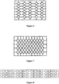
- FIGS 3 to 8 are schematic views showing that the carbon fiber strands of the first heating portion 10 are combined with the glass fiber cloth, in the figures, black lines are carbon fiber strands, and blank portions refer to the glass fiber cloth.
- the carbon fiber strands includes longitudinal carbon fiber strands and latitudinal carbon fiber strands arranged on the glass fiber cloth in a longitudinal direction and a latitudinal direction, respectively.
- the longitudinal carbon fiber strands and the latitudinal carbon fiber strands may be conductively connected to each other, to allow the carbon fiber strands to be connected with each other, and the heating effect of the melting device for the blade can be prevented from being affected by the breaking of a carbon fiber strand at a certain position.
- the longitudinal carbon fiber strands and the latitudinal carbon fiber strands of the first heating portion 10 may be arranged crosswise, and may form a polygonal line structure.
- the first heating portion 10 may be formed by overlapping and interweaving the longitudinal carbon fiber strands and the latitudinal carbon fiber strands with the glass fibers in the glass fiber cloth.
- the longitudinal carbon fiber strands and the latitudinal carbon fiber strands of the first heating portion 10 may be arranged crosswise to form a grid structure with the longitudinal carbon fiber strands and the latitudinal carbon fiber strands cross each other at each node.
- the longitudinal carbon fiber strands and the latitudinal carbon fiber strands may form an axis-symmetric structure, to satisfy the isobaric requirement of the first heating portion 10.
- the longitudinal carbon fiber strands and the latitudinal carbon fiber strands may forma carbon fiber strand module of a shape such as a diamond, and diamond-shaped modules are connected according to a predetermined pattern, to form a carbon fiber strand module set, thereby forming an axis-symmetric structure.
- the longitudinal carbon fiber strands and the latitudinal carbon fiber strands may form a cubic carbon fiber strand module, a diamond-shaped carbon fiber strand module, and a hexagonal carbon fiber strand module, these three shapes of carbon fiber strand modules may be connected according to a predetermined pattern, to from a carbon fiber strand module set, thereby forming an axis-symmetric structure.
- the carbon fiber strand module set may be formed first, and then the carbon fiber strand module set is bonded to the glass fiber cloth by using a connecting piece having high heat resistance.
- the carbon fiber strand module can be sewn to the glass fiber cloth by using a high-temperature resistant wire, or the carbon fiber strand module can be bonded to the glass fiber cloth by using a high-temperature resistant glue and then a flattening treatment is performed.
- edges of the carbon fiber strands that are not electrically connected to the first electrode 20 and the second electrode 30 may be overlocked.
- the longitudinal carbon fiber strands and the latitudinal carbon fiber strands may be formed into other forms of the carbon fiber strand module as required, as long as the carbon fiber strands can be connected to each other.
- a heating power of the ice melting device for the blade can be adjusted by adjusting the number of carbon fiber strand modules or spacing between adjacent carbon fiber strand modules or the shapes of the carbon fiber strand modules or the form of the combination of carbon fiber strand modules, or by adjusting the type or the number of the carbon fiber strands .
- the spacing between the carbon fiber strands can be determined by the severity of icing at a portion where the ice is required to be melted, the type of the carbon fiber, a rated power of the ice melting device for the blade, and a width and a length of the ice melting device for the blade.
- the ice melting device for the blade may be integrally formed with the blade through a vacuum infusion process when a new blade is formed, or the pre-impregnated ice melting device for the blade may be built in the old blade through a vacuum bag molding process and then other layers may be provided to form a complete blade.
- the first electrode 20 and the second electrode 30 may be current-conducting sheets, and the current-conducting sheets may be clamped on the carbon fiber strands to be conductively connected to the carbon fiber strands.
- the first electrode 20 and the second electrode 30 may be plated electrodes, that is, a portion of the carbon fiber strand which is required to be electrically connected may be plated with a metal to function as an electrode.
- the carbon fiber strands connecting to the first electrode 20 and the second electrode 30 may be arranged in a length direction of the blade, to improve an ice melting effect for the blade.
- the connecting conductor 40 may be a current-conducting sheet.
- the connecting conductor 40 may be sewn on the glass fiber cloth or arranged to run through the glass fiber cloth, to allow the connecting conductor 40 to be fixed.
- the connecting conductor 40 may be insulated from the first electrode 20 and the carbon fiber strands, to form an electrical circuit, so as to avoid a short circuit.
- the connecting conductor 40 is a current-conducting sheet, since the connecting conductor 40 is thin, in a case that the ice melting device for the blade is built in the blade and other layers are provided on the ice melting device for the blade to form a complete blade, partial protrusion of the layers due to a large thickness of the connecting conductor 40 may be prevented.
- the connecting conductor 40 is not limited to the current-conducting sheet, it may be other components which can function for electrical connection.
- a constant voltage power source may be powered on at the first electrode 20 and the second end of the connecting conductor 40, and a current flows through each of the carbon fiber strands and the carbon fiber strands are energized to heat, so as to melt the ice on the blade.
- the ice melting devices for the blade in Figures 1 and 2 may be used in cooperation, for example, the ice melting device for the blade in Figure 1 may be mounted on one of a PS surface (a pressure surface) and a SS surface (a suction surface) of the blade, and the ice melting device for the blade in Figure 2 may be mounted on the other of the PS surface and the SS surface of the blade, so that the power leads connecting to the first electrode 20 and the second electrode 30 can be located at a same side, but the arrangement is not limited to this.
- the ice melting device for the blade in Figure 1 may be mounted on one of a PS surface (a pressure surface) and a SS surface (a suction surface) of the blade
- the ice melting device for the blade in Figure 2 may be mounted on the other of the PS surface and the SS surface of the blade, so that the power leads connecting to the first electrode 20 and the second electrode 30 can be located at a same side, but the arrangement is not limited to this.
- the ice melting device for the blade in Figure 1 or the ice melting device for the blade in Figure 2 may also be used individually, that is, the ice melting devices for the blade in Figure 1 may be mounted on the PS surface and the SS surface respectively, and the ice melting devices for the blade of Figure 2 also may be mounted on the PS surface and the SS surface respectively. Furthermore, a size and the number of the ice melting device for the blade may be appropriately chosen according to an area of the blade where the ice is required to be melted.
- the ice melting device for the blade is not limited to this.
- an ice melting device for a blade according to a third embodiment and an ice melting device for a blade according to a fourth embodiment of the present application will be described with reference to Figures 9 and 10 .
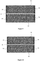
- Figure 9 is a schematic view showing the ice melting device for the blade according to the third embodiment of the present application.
- the ice melting device for the blade may further include a second heating portion 50, a third electrode 60, and a fourth electrode 70.
- the second heating portion 50 and the first heating portion 10 may be arranged side by side in a width direction of the first heating portion 10.
- the third electrode 60 and the fourth electrode 70 may be arranged at two ends of the second heating portion 50 in a length direction, respectively.
- the connecting conductor 40 may be located between the first heating portion 10 and the second heating portion 50.
- a first end of the connecting conductor 40 may be connected to the second electrode 30 of the first heating potion 10 and the fourth electrode 70 of the second heating portion 50 respectively.
- a second end of the connecting conductor 40 is located at a same side as the first electrode 20 and the third electrode 60.
- the configuration of the second heating portion 50 may be the same as that of the first heating portion 10.
- the configuration of the third electrode 60 and the fourth electrode 70 may also be the same as in the configuration of the first electrode 20 and the second electrode 30, respectively. Therefore, the description of the same components will be omitted for conciseness.
- the first electrode 20 of the first heating portion 10 and the third electrode 60 of the second heating portion 50, and the second end of the connecting conductor 40 may be connected to positive and negative power leads respectively, to form an electrical circuit.
- the first heating portion 10 and the second heating portion 50 may be integrally formed, and the first heating portion 10 and the second heating portion 50 may be connected by a glass fiber cloth.
- the connecting conductor 40 may be a current-conducting sheet, and the connecting conductor may be sewn on the glass fiber cloth connecting the first heating portion 10 and the second heating portion 50 or arranged to run through the glass fiber cloth, and may be insulated from the first electrode 20, the third electrode 60 and the carbon fiber strands.
- Figure 10 is a schematic view showing the ice melting device for the blade according to the fourth embodiment of the present application.
- the ice melting device for the blade according to the fourth embodiment of the present invention is different from the ice melting device for the blade according to the third embodiment of the present invention shown in Figure 9 in that, a predetermined space may be formed between the first heating portion 10 and the second heating portion 50.
- the connecting conductor may be a wire and is accommodated in the predetermined space.
- both the ice melting devices for the blade shown in Figures 9 and 10 include a second heating portion
- the blade may be laid integrally by laying the first heating portion and the second heating portion on the PS surface and the SS surface of the blade respectively, so as to save the time and cost for operation and maintenance.
- the blade is integrally laid, and the connecting conductor 40 is arranged at a joint between the PS and the SS surface thereby reducing the time and cost for operation and maintenance.
- the connecting conductor With the connecting conductor, power leads connecting to the first electrode and the second electrode are allowed be located at a same side, thereby, in a case that an old blade is modified, an increase of a layer thickness caused by the power leads may be greatly reduced. In addition, the cumbersome wiring work may be reduced and the power leads may be saved.
- the carbon fiber strands of the first heating portion is fixed by the first electrode and the second electrode and by an overlock treatment, which prevents the carbon fiber strands from loosing, so that the carbon fiber strands have a good performance in maintaining a stationary shape.
- the glass fibers as an insulating material, carbon fibers in a carbon fiber strand can be prevented from being mixed with the adjacent carbon fiber strands, thereby preventing a short circuit.
- the heating effect of the melting device for the blade can be prevented from being affected by the breaking of a carbon fiber strand at a certain position.
- the ice melting device for the blade may be designed to have different heating power according to the requirements of the blade, and may be integrally formed with a new blade or built in an old blade.
- the ice melting device for the blade has a simple manufacturing process and does not required to be assembled in use.
Landscapes
- Engineering & Computer Science (AREA)
- Mechanical Engineering (AREA)
- Sustainable Development (AREA)
- Sustainable Energy (AREA)
- Chemical & Material Sciences (AREA)
- Combustion & Propulsion (AREA)
- Life Sciences & Earth Sciences (AREA)
- General Engineering & Computer Science (AREA)
- Physics & Mathematics (AREA)
- Thermal Sciences (AREA)
- Resistance Heating (AREA)
- Crushing And Grinding (AREA)
- Working Measures On Existing Buildindgs (AREA)
- Shovels (AREA)
Abstract
Description
- The present application relates to the technical field of wind power generation, and in particular to an ice melting device for a blade, a blade having the ice melting device and a wind turbine.
- The operating environment of a wind turbine directly affects the power generation efficiency of the wind turbine. In the case that the wind turbine is operated under extreme weather conditions such as frost, cold wave and freezing rain, phenomena of ice (frost) coating and snow hanging on a blade may occur. Due to the phenomena of ice (frost) coating, snow hanging and the like of the blade, a cross-sectional shape of the blade of the wind turbine may be changed, which reduces the efficiency of wind energy absorption of the blade; a mechanical operation damage of the wind turbine may be caused, the load of the wind turbine may be increased, and the center of gravity may shift; the falling of ice blocks causes safety hazard to field personnel and field equipment; and the accuracy of wind measurement may also be affected, which brings proprietors serious economic loss of power generation. For example, the cumulative number of ice-covered days in a wind farm in Gansu Province from October 2016 to April 2017 was more than 60 days, and the cumulative power generation loss is at least 6770.056 thousand kilowatt hours.
- In order to solve the phenomena of ice (frost) coating, snow hanging, etc., the blade of the wind turbine is generally deiced. Currently, the deicing methods include passive anti-icing by a solution, mechanical deicing, air thermal anti-icing, microwave deicing, passive anti-icing by a endothermic coating, deicing by electromagnetic shock vibration, passive anti-icing by a waterproof coating, trembling deicing, electro-thermal active deicing, etc. The electro-thermal active deicing method not only has the advantages of high power, small influence on the aerodynamic shape and good maintainability, but also is simple and direct, has a high energy utilization rate and low economic cost, therefore, it is a relatively ideal deicing method and is currently the most widely used and best-performing method.
- An ice melting device for a blade which can perform active deicing by using electric energy is provided according to the present application.
- An ice melting device for a blade which has a novel structure and has excellent heating performance is provided according to the present application, to meet practical needs.
- According to an aspect of the present application, an ice melting device for a blade is provided. The ice melting device for the blade may include: a heating portion; a first electrode and a second electrode, wherein the first electrode and the second electrode are arranged at two ends of the first heating portion in a length direction, respectively; and a connecting conductor, wherein the connecting conductor extends in the length direction, a first end of the connecting conductor is connected to the second electrode, and a second end of the connecting conductor and the first electrode are located at a same side. With the connecting conductor, power leads connecting to the first electrode and the second electrode are allowed be located at a same side, thereby, in a case that an old blade is modified, an increase of a layer thickness caused by the power leads may be greatly reduced. In addition, the cumbersome wiring work may be reduced and the power leads may be saved.
- Preferably, the first heating portion includes a glass fiber cloth and carbon fiber strands, the carbon fiber strands are sewn on the glass fiber cloth or the carbon fiber strands are interwoven with glass fibers of the glass fiber cloth, to be integrated with the glass fiber cloth, and the carbon fiber strands are conductively connected to the first electrode and the second electrode.
- Preferably, the carbon fiber strands include longitudinal carbon fiber strands and latitudinal carbon fiber strands arranged on the glass fiber cloth in a longitudinal direction and a latitudinal direction respectively, and the longitudinal carbon fiber strands and the latitudinal carbon fiber strands are conductively connected to each other. With the mutual conduction between the longitudinal carbon fiber strands and the latitudinal carbon fiber strands, the heating effect of the melting device for the blade can be prevented from being affected by the breaking of a carbon fiber strand at a certain position.
- Preferably, the longitudinal carbon fiber strands and the latitudinal carbon fiber strands are arranged crosswise, to form a grid structure with the longitudinal carbon fiber strands and the latitudinal carbon fiber strands cross each other at each node.
- Preferably, the connecting conductor is a current-conducting sheet, the connecting conductor is sewn on the glass fiber cloth or arranged to run through the glass fiber cloth, and the connecting conductor is insulated from the first electrode and the carbon fiber strands. By insulating the connecting conductor from the first electrode and the carbon fiber strands, an electrical circuit is formed to avoid a short circuit.
- Preferably, the heating device may further include: a second heating portion, wherein the heating portion and the first heating portion may be arranged side by side in a width direction of the first heating portion; a third electrode and a fourth electrode, wherein the third electrode and the fourth electrode may be arranged at two ends of the second heating portion in a length direction, respectively; the connecting conductor is located between the first heating portion and the second heating portion, and a first end of the connecting conductor may be connected to the second electrode and the fourth electrode respectively, and a second end of the connecting conductor may be located at a same side as the first electrode and the third electrode. Since the heating device includes the first heating portion and the second heating portion, a blade may be laid integrally by laying the first heating portion and the second heating portion on a pressure surface and a suction surface of the blade respectively, so as to save the time and cost for operation and maintenance.
- Preferably, the first heating portion and the second heating portion may be connected through a glass fiber cloth, the connecting conductor may be a current-conducting sheet and may be sewn on the glass fiber cloth connecting the first heating portion and the second heating portion or may be arranged to run through the glass fiber cloth, the connecting conductor is insulated from the first electrode, the third electrode and the carbon fiber strands. In a case that the first heating portion and the second heating portion are arranged on the pressure surface and the suction surface of the blade respectively, the connecting conductor may be located at a joint between the pressure surface and the suction surface.
- Preferably, a predetermined space is formed between the first heating portion and the second heating portion, the connecting conductor may be a wire and may be accommodated in the predetermined space. In a case that the first heating portion and the second heating portion are arranged on the pressure surface and the suction surface of the blade respectively, the connecting conductor may be located at the joint between the pressure surface and the suction surface.
- According to another aspect of the present application, a blade is provided. The blade includes the ice melting device described above, and the ice melting device is built in the blade.
- According to another aspect of the present application, a wind turbine is provided. The wind turbine includes the blade described above.
- According to the ice melting device for the blade of the present application, with the connecting conductor, power leads connecting to the first electrode and the second electrode are allowed be located at a same side, thereby, in a case that an old blade is modified, an increase of a layer thickness caused by the power leads may be greatly reduced. In addition, the cumbersome wiring work may be reduced and the power leads may be saved.
- In addition, according to the ice melting device for the bladeof the embodiment of the present application, the carbon fiber strands of the first heating portion is fixed by the first electrode and the second electrode and by an overlock treatment, which prevents the carbon fiber strands from loosing, so that the carbon fiber strands have a good performance in maintaining a stationary shape.
- Besides, according to the ice melting device for the blade of the embodiment of the present application, by using the glass fibers as an insulating material, carbon fibers in a carbon fiber strand can be prevented from being mixed with the adjacent carbon fiber strands, thereby preventing a short circuit.
- Moreover, according to the ice melting device for the blade of the embodiment of the present application, since the longitudinal carbon fiber strands and the latitudinal carbon fiber strands are conductively connected to each other, the heating effect of the melting device for the blade can be prevented from being affected by the breaking of a carbon fiber strand at a certain position.
- Further, the ice melting device for the blade according to the embodiment of the present application may be designed to have different heating power according to the requirements of the blade, and may be integrally formed with a new blade or built in an old blade.
- Furthermore, the ice melting device for the blade according to the embodiment of the present application has a simple manufacturing process and does not required to be assembled in use.
- The above and other objects and features of the present application will be clearer from the following description of embodiments in conjunction with the drawings.
-
Figure 1 is a schematic view showing an ice melting device for a blade according to a first embodiment of the present application. -
Figure 2 is a schematic view showing an ice melting device for a blade according to a second embodiment of the present application. -
Figures 3 to 8 are schematic views showing that carbon fiber strands and a glass fiber cloth of a first heating portion are in combination. -
Figure 9 is a schematic view showing an ice melting device for a blade according to a third embodiment of the present application. -
Figure 10 is a schematic view showing an ice melting device for a blade according to a fourth embodiment of the present application. - The embodiments according to the present application will be described in detail with reference to the drawings, the embodiments are shown in the drawings, and the same numeral always represents the same component.
-
Figure 1 and Figure 2 show an ice melting device for a blade according to an first embodiment and a second embodiment of the present application, respectively. Hereinafter, a specific structure of the ice melting device for the blade will be described with reference toFigures 1 and 2 . - As shown in
Figures 1 and 2 , an ice melting device for a blade may include afirst heating portion 10, afirst electrode 20 and asecond electrode 30, and a connectingconductor 40. Specifically, thefirst electrode 20 and thesecond electrode 20 may be arranged at two ends of thefirst heating portion 10 in a length direction, respectively, to be electrically connected to thefirst heating portion 10. Theconnecting conductor 40 may extend in the length direction of thefirst heating portion 10,a first end of the connectingconductor 40 may be connected to thesecond electrode 20, and a second end of the connectingconductor 40 and thefirst electrode 20 may be located at a same side. - The connecting
conductor 40 and thefirst electrode 20 may be connected to a positive power lead and a negative power lead at the same side, respectively, to allow thefirst heating portion 10, thefirst electrode 20 and thesecond electrode 30, and the connectingconductor 40 to form an electrical circuit, so that thefirst heating portion 10 is energized to heat. Since the power leads connecting thefirst electrode 20 and thesecond electrode 30 are arranged at the same side, compared with the method of connecting thefirst electrode 20 and thesecond electrode 30 to the power leads at the two ends of thefirst heating portion 10 respectively, an increase of a layer thickness caused by the power leads may be greatly reduced in a case that an old blade is modified. In addition, the cumbersome wiring work may be reduced and the power leads may be saved. - The ice melting device for the blade in
Figure 1 is different from the ice melting device for the blade inFigure 2 in terms of a position of the connectingconductor 40 and a position of connecting the connectingconductor 40 and thesecond electrode 30. Specifically, inFigure 1 , theconnecting conductor 40 is located at a first side of thefirst electrode 20, and a second end of the connectingconductor 40 is connected to a first end of thesecond electrode 30. However, inFigure 2 , the connectingconductor 40 is located at a second side of thefirst electrode 20 opposite to the first side, and the second end of the connectingconductor 40 is connected to a second end of thesecond electrode 30 opposite to the first end. It should be understood that, the above description is bases on the states of the ice melting device for the blade shown inFigures 1 and 2 , regardless of the state of the ice melting device for the blade in actual use. - The
first heating portion 10, thefirst electrode 20 and thesecond electrode 30, and the connectingconductor 40 will be described in detail hereinafter. - The
first heating portion 10 may include a glass fiber cloth and carbon fiber strands. According to the design of thefirst heating portion 10, the carbon fiber strands are sewn on the glass fiber cloth, or the carbon fiber strands are interwoven with glass fibers of the glass fiber cloth, to be integrated with the glass fiber cloth. The carbon fiber strands may be conductively connected to thefirst electrode 20 and thesecond electrode 30, to form an electrical circuit. - Both carbon fibers and glass fibers are polymer materials, which have features of high heat resistance, high mechanical strength, soft texture, etc., they are easily processed, easy to be combined with composite materials of the blade, and can improve the mechanical strength of the blade. Carbon fiber has advantages such as low specific gravity, high strength, low density, high elasticity, high corrosion resistance, high temperature resistance, high wear resistance, high thermal efficiency, good electrical and thermal conductivity, etc. The strength of the carbon fiber is four times that of ordinary steel and its specific gravity is only equal to 1/4 that of steel, the carbon fiber has light and tough physical properties and stable electrical resistivity. Glass fiber has a good insulation performance, which prevents a carbon fiber strand from being mixed with the adjacent carbon fiber strands, so as to prevent a short circuit.
-
Figures 3 to 8 are schematic views showing that the carbon fiber strands of thefirst heating portion 10 are combined with the glass fiber cloth, in the figures, black lines are carbon fiber strands, and blank portions refer to the glass fiber cloth. The carbon fiber strands includes longitudinal carbon fiber strands and latitudinal carbon fiber strands arranged on the glass fiber cloth in a longitudinal direction and a latitudinal direction, respectively. The longitudinal carbon fiber strands and the latitudinal carbon fiber strands may be conductively connected to each other, to allow the carbon fiber strands to be connected with each other, and the heating effect of the melting device for the blade can be prevented from being affected by the breaking of a carbon fiber strand at a certain position. - Specifically, as shown in
Figure 3 , the longitudinal carbon fiber strands and the latitudinal carbon fiber strands of thefirst heating portion 10 may be arranged crosswise, and may form a polygonal line structure. In this structure, since the structure formed by the carbon fiber strands is relatively simple, thefirst heating portion 10 may be formed by overlapping and interweaving the longitudinal carbon fiber strands and the latitudinal carbon fiber strands with the glass fibers in the glass fiber cloth. - As shown in
Figures 4 to 8 , the longitudinal carbon fiber strands and the latitudinal carbon fiber strands of thefirst heating portion 10 may be arranged crosswise to form a grid structure with the longitudinal carbon fiber strands and the latitudinal carbon fiber strands cross each other at each node. For example, the longitudinal carbon fiber strands and the latitudinal carbon fiber strands may form an axis-symmetric structure, to satisfy the isobaric requirement of thefirst heating portion 10. Specifically, as shown inFigures 4 to 7 , the longitudinal carbon fiber strands and the latitudinal carbon fiber strands may forma carbon fiber strand module of a shape such as a diamond, and diamond-shaped modules are connected according to a predetermined pattern, to form a carbon fiber strand module set, thereby forming an axis-symmetric structure. As shown inFigure 8 , the longitudinal carbon fiber strands and the latitudinal carbon fiber strands may form a cubic carbon fiber strand module, a diamond-shaped carbon fiber strand module, and a hexagonal carbon fiber strand module, these three shapes of carbon fiber strand modules may be connected according to a predetermined pattern, to from a carbon fiber strand module set, thereby forming an axis-symmetric structure. - When the
first heating portion 10 according toFigures 4 to 8 is formed, since the structure formed by the carbon fiber strands is relatively complex, the carbon fiber strand module set may be formed first, and then the carbon fiber strand module set is bonded to the glass fiber cloth by using a connecting piece having high heat resistance. For example, the carbon fiber strand module can be sewn to the glass fiber cloth by using a high-temperature resistant wire, or the carbon fiber strand module can be bonded to the glass fiber cloth by using a high-temperature resistant glue and then a flattening treatment is performed. In order to make the carbon fiber strands have a good performance in maintaining a stationary shape, edges of the carbon fiber strands that are not electrically connected to thefirst electrode 20 and thesecond electrode 30 may be overlocked. - Although the specific forms of the combination of the carbon fiber strands and the glass fiber cloth are described above, the specific forms are not limited to this. The longitudinal carbon fiber strands and the latitudinal carbon fiber strands may be formed into other forms of the carbon fiber strand module as required, as long as the carbon fiber strands can be connected to each other.
- In addition, according to an actual demand of heating intensity or a power requirement of a slip ring of different types of wind turbine, a heating power of the ice melting device for the blade can be adjusted by adjusting the number of carbon fiber strand modules or spacing between adjacent carbon fiber strand modules or the shapes of the carbon fiber strand modules or the form of the combination of carbon fiber strand modules, or by adjusting the type or the number of the carbon fiber strands . The spacing between the carbon fiber strands can be determined by the severity of icing at a portion where the ice is required to be melted, the type of the carbon fiber, a rated power of the ice melting device for the blade, and a width and a length of the ice melting device for the blade.
- Besides, through a mass density of the carbon fiber strands and the glass fibers may be changed by adjusting the type or a tightness degree of weaving of the carbon fiber strands and glass fibers, and then the requirements of vacuum infusion, vacuum bag molding and pre-impregnation, so that the ice melting device for the blade is not only suitable to be integrally formed with a new blade, but also suitable to be built in an old blade. Specifically, the ice melting device for the blade may be integrally formed with the blade through a vacuum infusion process when a new blade is formed, or the pre-impregnated ice melting device for the blade may be built in the old blade through a vacuum bag molding process and then other layers may be provided to form a complete blade.
- Moreover, in the present embodiment, the
first electrode 20 and thesecond electrode 30 may be current-conducting sheets, and the current-conducting sheets may be clamped on the carbon fiber strands to be conductively connected to the carbon fiber strands. Optionally, thefirst electrode 20 and thesecond electrode 30 may be plated electrodes, that is, a portion of the carbon fiber strand which is required to be electrically connected may be plated with a metal to function as an electrode. During use, the carbon fiber strands connecting to thefirst electrode 20 and thesecond electrode 30 may be arranged in a length direction of the blade, to improve an ice melting effect for the blade. - Optionally, the connecting
conductor 40 may be a current-conducting sheet. The connectingconductor 40 may be sewn on the glass fiber cloth or arranged to run through the glass fiber cloth, to allow the connectingconductor 40 to be fixed. In addition, the connectingconductor 40 may be insulated from thefirst electrode 20 and the carbon fiber strands, to form an electrical circuit, so as to avoid a short circuit. In a cast that the connectingconductor 40 is a current-conducting sheet, since the connectingconductor 40 is thin, in a case that the ice melting device for the blade is built in the blade and other layers are provided on the ice melting device for the blade to form a complete blade, partial protrusion of the layers due to a large thickness of the connectingconductor 40 may be prevented. However, the connectingconductor 40 is not limited to the current-conducting sheet, it may be other components which can function for electrical connection. - When the ice melting devices for the blade according to the first embodiment and the second embodiment are used to melt the ice on the blade, a constant voltage power source may be powered on at the
first electrode 20 and the second end of the connectingconductor 40, and a current flows through each of the carbon fiber strands and the carbon fiber strands are energized to heat, so as to melt the ice on the blade. - In addition, according to the actual demands, the ice melting devices for the blade in
Figures 1 and 2 may be used in cooperation, for example, the ice melting device for the blade inFigure 1 may be mounted on one of a PS surface (a pressure surface) and a SS surface (a suction surface) of the blade, and the ice melting device for the blade inFigure 2 may be mounted on the other of the PS surface and the SS surface of the blade, so that the power leads connecting to thefirst electrode 20 and thesecond electrode 30 can be located at a same side, but the arrangement is not limited to this. For instance, according to the actual demands, the ice melting device for the blade inFigure 1 or the ice melting device for the blade inFigure 2 may also be used individually, that is, the ice melting devices for the blade inFigure 1 may be mounted on the PS surface and the SS surface respectively, and the ice melting devices for the blade ofFigure 2 also may be mounted on the PS surface and the SS surface respectively. Furthermore, a size and the number of the ice melting device for the blade may be appropriately chosen according to an area of the blade where the ice is required to be melted. - Although the specific structure of the ice melting device for the blade is described in detail above with reference to
Figures 1 to 8 , the ice melting device for the blade is not limited to this. Hereinafter, an ice melting device for a blade according to a third embodiment and an ice melting device for a blade according to a fourth embodiment of the present application will be described with reference toFigures 9 and 10 . -
Figure 9 is a schematic view showing the ice melting device for the blade according to the third embodiment of the present application. - As shown in
Figure 9 , in addition to thefirst heating portion 10, thefirst electrode 20 and thesecond electrode 30, and the connectingconductor 40, the ice melting device for the blade may further include asecond heating portion 50, athird electrode 60, and afourth electrode 70. - The
second heating portion 50 and thefirst heating portion 10 may be arranged side by side in a width direction of thefirst heating portion 10. Thethird electrode 60 and thefourth electrode 70 may be arranged at two ends of thesecond heating portion 50 in a length direction, respectively. The connectingconductor 40 may be located between thefirst heating portion 10 and thesecond heating portion 50. A first end of the connectingconductor 40 may be connected to thesecond electrode 30 of thefirst heating potion 10 and thefourth electrode 70 of thesecond heating portion 50 respectively. A second end of the connectingconductor 40 is located at a same side as thefirst electrode 20 and thethird electrode 60. - The configuration of the
second heating portion 50 may be the same as that of thefirst heating portion 10. The configuration of thethird electrode 60 and thefourth electrode 70 may also be the same as in the configuration of thefirst electrode 20 and thesecond electrode 30, respectively. Therefore, the description of the same components will be omitted for conciseness. - When the ice melting device for the blade is used, the
first electrode 20 of thefirst heating portion 10 and thethird electrode 60 of thesecond heating portion 50, and the second end of the connectingconductor 40 may be connected to positive and negative power leads respectively, to form an electrical circuit. Optionally, thefirst heating portion 10 and thesecond heating portion 50 may be integrally formed, and thefirst heating portion 10 and thesecond heating portion 50 may be connected by a glass fiber cloth. In this case, the connectingconductor 40 may be a current-conducting sheet, and the connecting conductor may be sewn on the glass fiber cloth connecting thefirst heating portion 10 and thesecond heating portion 50 or arranged to run through the glass fiber cloth, and may be insulated from thefirst electrode 20, thethird electrode 60 and the carbon fiber strands. -
Figure 10 is a schematic view showing the ice melting device for the blade according to the fourth embodiment of the present application. - The ice melting device for the blade according to the fourth embodiment of the present invention is different from the ice melting device for the blade according to the third embodiment of the present invention shown in
Figure 9 in that, a predetermined space may be formed between thefirst heating portion 10 and thesecond heating portion 50. In this case, the connecting conductor may be a wire and is accommodated in the predetermined space. - As described above, since both the ice melting devices for the blade shown in
Figures 9 and 10 include a second heating portion, the blade may be laid integrally by laying the first heating portion and the second heating portion on the PS surface and the SS surface of the blade respectively, so as to save the time and cost for operation and maintenance. The blade is integrally laid, and the connectingconductor 40 is arranged at a joint between the PS and the SS surface thereby reducing the time and cost for operation and maintenance. - According to the ice melting device for the blade of the present application, with the connecting conductor, power leads connecting to the first electrode and the second electrode are allowed be located at a same side, thereby, in a case that an old blade is modified, an increase of a layer thickness caused by the power leads may be greatly reduced. In addition, the cumbersome wiring work may be reduced and the power leads may be saved.
- In addition, according to the ice melting device for the bladeof the embodiment of the present application, the carbon fiber strands of the first heating portion is fixed by the first electrode and the second electrode and by an overlock treatment, which prevents the carbon fiber strands from loosing, so that the carbon fiber strands have a good performance in maintaining a stationary shape.
- Besides, according to the ice melting device for the blade of the embodiment of the present application, by using the glass fibers as an insulating material, carbon fibers in a carbon fiber strand can be prevented from being mixed with the adjacent carbon fiber strands, thereby preventing a short circuit.
- Moreover, according to the ice melting device for the blade of the embodiment of the present application, since the longitudinal carbon fiber strands and the latitudinal carbon fiber strands are conductively connected to each other, the heating effect of the melting device for the blade can be prevented from being affected by the breaking of a carbon fiber strand at a certain position.
- Further, the ice melting device for the blade according to the embodiment of the present application may be designed to have different heating power according to the requirements of the blade, and may be integrally formed with a new blade or built in an old blade.
- Furthermore, the ice melting device for the blade according to the embodiment of the present application has a simple manufacturing process and does not required to be assembled in use.
- Although the embodiments of the present application are described in detail hereinbefore, various modifications and variations can be made to the embodiments of the present application by those skilled in the art without departing from the spirit and scope of the present application. However, it should be understood by those skilled in the art that these modifications and variations still fall in the spirit and scope of the embodiments of the present application as defined by the appended claims.
| 10 | first heating portion, | 20 | first electrode, |
| 30 | second electrode, | 40 | connecting conductor, |
| 50 | second heating portion, | 60 | third electrode, |
| 70 | fourth electrode. |
Claims (10)
- An ice melting device for a blade, comprising:a first heating portion (10);a first electrode (20) and a second electrode (30), wherein the first electrode (20) and the second electrode (30) are arranged at two ends of the first heating portion (10) in a length direction, respectively; anda connecting conductor (40), wherein the connection conductor (40) extends in the length direction, a first end of the connecting conductor (40) is connected to the second electrode (30), and a second end of the connecting conductor (40) and the first electrode (20) are located at a same side.
- The ice melting device for the blade according to claim 1, wherein the first heating portion (10) comprises a glass fiber cloth and carbon fiber strands, and the carbon fiber strands are sewn on the glass fiber cloth or the carbon fiber strands are interwoven with glass fibers of the glass fiber cloth, to be integrated with the glass fiber cloth, and the carbon fiber strands are conductively connected to the first electrode (20) and the second electrode (30).
- The ice melting device for the blade according to claim 2, wherein the carbon fiber strands comprise longitudinal carbon fiber strands and latitudinal carbon fiber strands arranged on the glass fiber cloth in a longitudinal direction and a latitudinal direction respectively, and the longitudinal carbon fiber strands and the latitudinal carbon fiber strands are conductively connected to each other.
- The ice melting device for the blade according to claim 3, wherein the longitudinal carbon fiber strands and the latitudinal carbon fiber strands are arranged crosswise, to form a grid structure with the longitudinal carbon fiber strands and the latitudinal carbon fiber strands cross each other at each node.
- The ice melting device for the blade according to any one of claims 2 to 4, wherein the connecting conductor (40) is a current-conducting sheet, the connecting conductor (40) is sewn on the glass fiber cloth or arranged to run through the glass fiber cloth, and the connecting conductor (40) is insulated from the first electrode (20) and the carbon fiber strands.
- The ice melting device for the blade according to any one of claims 2 to 4, further comprising:a second heating portion (50), wherein the second heating portion (50) and the first heating portion (10) are arranged side by side in a width direction of the first heating portion (10); anda third electrode (60) and a fourth electrode (70), wherein the third electrode (60) and the fourth electrode (70) are arranged at two ends of the second heating portion (50) in a length direction, respectively; whereinthe connecting conductor (40) is located between the first heating portion (10) and the second heating portion (50), a first end of the connecting conductor (40) is connected to the second electrode (30) and the fourth electrode (70) respectively, and a second end of the connecting conductor (40) is located at a same side as the first electrode (20) and the third electrode (60).
- The ice melting device for the blade according to claim 6, wherein the first heating portion (10) and the second heating portion (50) are connected through a glass fiber cloth, the connecting conductor (40) is a current-conducting sheet and is sewn on the glass fiber cloth connecting the first heating portion (10) and the second heating portion (50) or arranged to run through the glass fiber cloth, and the connecting conductor (40) is insulated from the first electrode (20), the third electrode (60), and the carbon fiber strands; and
in a case that the first heating portion (10) and the second heating portion (50) are arranged on a pressure surface and a suction surface of a blade respectively, the connecting conductor (40) is located at a joint between the pressure surface and the suction surface. - The ice melting device for the blade according to claim 6, wherein a predetermined space is formed between the first heating portion (10) and the second heating portion (50), the connecting conductor (40) is a wire and is accommodated in the predetermined space; in a case that the first heating portion (10) and the second heating portion (50) are arranged on a pressure surface and a suction surface of a blade respectively, the connecting conductor (40) is located at a joint between the pressure surface and the suction surface.
- A blade, comprising the ice melting device for the blade according to any one of claims 1 to 8, wherein the ice melting device for the blade is built in the blade.
- A wind turbine, comprising the blade according to claim 9.
Applications Claiming Priority (1)
| Application Number | Priority Date | Filing Date | Title |
|---|---|---|---|
| CN201810161119.5A CN110195690B (en) | 2018-02-27 | 2018-02-27 | Blade ice melting device, blade and wind generating set |
Publications (2)
| Publication Number | Publication Date |
|---|---|
| EP3530938A1 true EP3530938A1 (en) | 2019-08-28 |
| EP3530938B1 EP3530938B1 (en) | 2023-05-24 |
Family
ID=65529476
Family Applications (1)
| Application Number | Title | Priority Date | Filing Date |
|---|---|---|---|
| EP19158712.0A Active EP3530938B1 (en) | 2018-02-27 | 2019-02-22 | Ice melting device for blade, blade and wind turbine |
Country Status (6)
| Country | Link |
|---|---|
| US (1) | US20190264659A1 (en) |
| EP (1) | EP3530938B1 (en) |
| CN (1) | CN110195690B (en) |
| CA (1) | CA3032850A1 (en) |
| DK (1) | DK3530938T3 (en) |
| ES (1) | ES2952970T3 (en) |
Cited By (1)
| Publication number | Priority date | Publication date | Assignee | Title |
|---|---|---|---|---|
| EP3869035A1 (en) * | 2020-02-21 | 2021-08-25 | Siemens Gamesa Renewable Energy Innovation & Technology, S.L. | Blade for a rotor of a wind turbine and manufacturing method thereof |
Families Citing this family (6)
| Publication number | Priority date | Publication date | Assignee | Title |
|---|---|---|---|---|
| CN111692041B (en) * | 2020-06-28 | 2022-02-15 | 江南大学 | Flexible inflatable wind power generation blade and preparation method thereof |
| GB202016823D0 (en) * | 2020-10-23 | 2020-12-09 | Blade Dynamics Ltd | A wind turbine rotor blade with a leading edge member |
| CN113530768A (en) * | 2021-08-16 | 2021-10-22 | 上海工程技术大学 | Fan blade device that can remove snow based on carbon fiber is electrically conductive to generate heat |
| CN114084348B (en) * | 2021-11-22 | 2024-03-29 | 西安热工研究院有限公司 | Microwave deicing method for wind power blade |
| CN115144928B (en) * | 2022-07-01 | 2025-01-21 | 中国电子技术标准化研究院 | A composite structure for detecting and melting ice on a surface and a method thereof |
| CN118959251B (en) * | 2024-07-30 | 2025-09-16 | 南方电网科学研究院有限责任公司 | Method, device, equipment and storage medium for calculating ice coverage range of wind turbine blades |
Citations (5)
| Publication number | Priority date | Publication date | Assignee | Title |
|---|---|---|---|---|
| WO2007136260A1 (en) * | 2006-05-24 | 2007-11-29 | Stichting Materials Innovation Institute (M2I) | Heated aerodynamic profile for composite structures |
| WO2012164167A1 (en) * | 2011-05-31 | 2012-12-06 | Teknologian Tutkimuskeskus Vtt | Wind turbine blade and related method of manufacture |
| EP2754891A1 (en) * | 2013-01-14 | 2014-07-16 | Siemens Aktiengesellschaft | Wind turbine rotor blade de-icing arrangement |
| EP3109465A1 (en) * | 2015-06-26 | 2016-12-28 | Nordex Energy GmbH | Wind energy assembly rotor blade with an electric heating device |
| CN107642465A (en) * | 2017-10-27 | 2018-01-30 | 刘中威 | Wind power generating set and its blade deicing device |
Family Cites Families (6)
| Publication number | Priority date | Publication date | Assignee | Title |
|---|---|---|---|---|
| CN1152605C (en) * | 2001-04-25 | 2004-06-02 | 张汝昆 | Wide electrothermal band of active carbon fibres and its preparing process |
| CN2484715Y (en) * | 2001-05-08 | 2002-04-03 | 田沃 | Carbon-fiber insulation fire-retardent electrothermal decorative plate |
| CN2496912Y (en) * | 2001-09-27 | 2002-06-26 | 田沃 | Carbon fiber flat-plate electric-heating clothes changer |
| CN2518712Y (en) * | 2002-02-07 | 2002-10-30 | 马放 | Electric heating infrared radiation artistic painting |
| FI10797U1 (en) * | 2014-12-04 | 2015-03-10 | Wicetec Oy | A conductor joint for connecting a copper conductor |
| CN106671451B (en) * | 2016-06-08 | 2019-08-23 | 中国科学院苏州纳米技术与纳米仿生研究所 | Fibre reinforced composites, preparation method and application |
-
2018
- 2018-02-27 CN CN201810161119.5A patent/CN110195690B/en active Active
-
2019
- 2019-02-04 CA CA3032850A patent/CA3032850A1/en not_active Abandoned
- 2019-02-20 US US16/280,408 patent/US20190264659A1/en not_active Abandoned
- 2019-02-22 DK DK19158712.0T patent/DK3530938T3/en active
- 2019-02-22 EP EP19158712.0A patent/EP3530938B1/en active Active
- 2019-02-22 ES ES19158712T patent/ES2952970T3/en active Active
Patent Citations (5)
| Publication number | Priority date | Publication date | Assignee | Title |
|---|---|---|---|---|
| WO2007136260A1 (en) * | 2006-05-24 | 2007-11-29 | Stichting Materials Innovation Institute (M2I) | Heated aerodynamic profile for composite structures |
| WO2012164167A1 (en) * | 2011-05-31 | 2012-12-06 | Teknologian Tutkimuskeskus Vtt | Wind turbine blade and related method of manufacture |
| EP2754891A1 (en) * | 2013-01-14 | 2014-07-16 | Siemens Aktiengesellschaft | Wind turbine rotor blade de-icing arrangement |
| EP3109465A1 (en) * | 2015-06-26 | 2016-12-28 | Nordex Energy GmbH | Wind energy assembly rotor blade with an electric heating device |
| CN107642465A (en) * | 2017-10-27 | 2018-01-30 | 刘中威 | Wind power generating set and its blade deicing device |
Cited By (1)
| Publication number | Priority date | Publication date | Assignee | Title |
|---|---|---|---|---|
| EP3869035A1 (en) * | 2020-02-21 | 2021-08-25 | Siemens Gamesa Renewable Energy Innovation & Technology, S.L. | Blade for a rotor of a wind turbine and manufacturing method thereof |
Also Published As
| Publication number | Publication date |
|---|---|
| EP3530938B1 (en) | 2023-05-24 |
| ES2952970T3 (en) | 2023-11-07 |
| US20190264659A1 (en) | 2019-08-29 |
| CA3032850A1 (en) | 2019-08-27 |
| CN110195690A (en) | 2019-09-03 |
| CN110195690B (en) | 2023-03-24 |
| DK3530938T3 (en) | 2023-06-12 |
Similar Documents
| Publication | Publication Date | Title |
|---|---|---|
| EP3530938B1 (en) | Ice melting device for blade, blade and wind turbine | |
| CN107642465B (en) | Wind generating set and blade deicing device thereof | |
| EP2526292B1 (en) | Fixation of a heating mat to a blade of a wind turbine | |
| EP0737148B1 (en) | Variable power density heating using stranded resistance wire | |
| US2757273A (en) | De-icer | |
| EP2526294A1 (en) | Heating mats arranged in a loop on a blade | |
| CN202171375U (en) | Chassis anti-icing structure and air conditioner | |
| CN102878026A (en) | Wind driven generator rotor blade with electrothermal deicing devices | |
| CN114104299B (en) | Device and method for preventing and removing ice by compounding superhydrophobic coating plasma and graphene electric heating | |
| US4841124A (en) | Strain-resistant heated helicopter rotor blade | |
| CN106321372B (en) | Composite carbon fiber heating element suitable for anti-icing/melting of wind turbine blades | |
| CN105952590A (en) | Heatable front edge flange plate for wind power blade | |
| CN103215729B (en) | Carbon fiber-containing electro-thermal fabric suitable for severe environment | |
| CN206856671U (en) | A kind of commercial car front windshield electrically heated glass | |
| CA3109841A1 (en) | Blade for a rotor of a wind turbine and manufacturing method thereof | |
| CN103194842B (en) | Metal-wire-containing electric heating fabric suitable for severe environment | |
| CN116750194B (en) | Modular anti-icing and de-icing system and method compatible with electric heating and lightning protection | |
| CN101303917B (en) | Self-heating freezing-proof overhead conductor | |
| CN207437277U (en) | Wind power generating set and its blade thawing apparatus | |
| CN202883274U (en) | Wind generator rotor blade with electric heating ice melting device | |
| EP3530937B1 (en) | Electric heating module structure, installation method and forming method thereof, and wind turbine | |
| CN211766326U (en) | Heating unit for heating aircraft equipment | |
| CN114635833B (en) | Anti-icing wind turbine blade and wind turbine generator | |
| CN210882020U (en) | Defrosting heater for cab | |
| CN201222373Y (en) | Transmission conductor with heating function |
Legal Events
| Date | Code | Title | Description |
|---|---|---|---|
| PUAI | Public reference made under article 153(3) epc to a published international application that has entered the european phase |
Free format text: ORIGINAL CODE: 0009012 |
|
| STAA | Information on the status of an ep patent application or granted ep patent |
Free format text: STATUS: REQUEST FOR EXAMINATION WAS MADE |
|
| 17P | Request for examination filed |
Effective date: 20190222 |
|
| AK | Designated contracting states |
Kind code of ref document: A1 Designated state(s): AL AT BE BG CH CY CZ DE DK EE ES FI FR GB GR HR HU IE IS IT LI LT LU LV MC MK MT NL NO PL PT RO RS SE SI SK SM TR |
|
| AX | Request for extension of the european patent |
Extension state: BA ME |
|
| STAA | Information on the status of an ep patent application or granted ep patent |
Free format text: STATUS: EXAMINATION IS IN PROGRESS |
|
| 17Q | First examination report despatched |
Effective date: 20210326 |
|
| GRAP | Despatch of communication of intention to grant a patent |
Free format text: ORIGINAL CODE: EPIDOSNIGR1 |
|
| STAA | Information on the status of an ep patent application or granted ep patent |
Free format text: STATUS: GRANT OF PATENT IS INTENDED |
|
| INTG | Intention to grant announced |
Effective date: 20221128 |
|
| GRAS | Grant fee paid |
Free format text: ORIGINAL CODE: EPIDOSNIGR3 |
|
| GRAA | (expected) grant |
Free format text: ORIGINAL CODE: 0009210 |
|
| STAA | Information on the status of an ep patent application or granted ep patent |
Free format text: STATUS: THE PATENT HAS BEEN GRANTED |
|
| AK | Designated contracting states |
Kind code of ref document: B1 Designated state(s): AL AT BE BG CH CY CZ DE DK EE ES FI FR GB GR HR HU IE IS IT LI LT LU LV MC MK MT NL NO PL PT RO RS SE SI SK SM TR |
|
| REG | Reference to a national code |
Ref country code: GB Ref legal event code: FG4D |
|
| REG | Reference to a national code |
Ref country code: CH Ref legal event code: EP |
|
| REG | Reference to a national code |
Ref country code: DE Ref legal event code: R096 Ref document number: 602019029166 Country of ref document: DE |
|
| REG | Reference to a national code |
Ref country code: DK Ref legal event code: T3 Effective date: 20230608 |
|
| REG | Reference to a national code |
Ref country code: AT Ref legal event code: REF Ref document number: 1569623 Country of ref document: AT Kind code of ref document: T Effective date: 20230615 |
|
| REG | Reference to a national code |
Ref country code: IE Ref legal event code: FG4D |
|
| REG | Reference to a national code |
Ref country code: RO Ref legal event code: EPE |
|
| REG | Reference to a national code |
Ref country code: LT Ref legal event code: MG9D |
|
| REG | Reference to a national code |
Ref country code: NL Ref legal event code: MP Effective date: 20230524 |
|
| REG | Reference to a national code |
Ref country code: AT Ref legal event code: MK05 Ref document number: 1569623 Country of ref document: AT Kind code of ref document: T Effective date: 20230524 |
|
| PG25 | Lapsed in a contracting state [announced via postgrant information from national office to epo] |
Ref country code: SE Free format text: LAPSE BECAUSE OF FAILURE TO SUBMIT A TRANSLATION OF THE DESCRIPTION OR TO PAY THE FEE WITHIN THE PRESCRIBED TIME-LIMIT Effective date: 20230524 Ref country code: PT Free format text: LAPSE BECAUSE OF FAILURE TO SUBMIT A TRANSLATION OF THE DESCRIPTION OR TO PAY THE FEE WITHIN THE PRESCRIBED TIME-LIMIT Effective date: 20230925 Ref country code: NO Free format text: LAPSE BECAUSE OF FAILURE TO SUBMIT A TRANSLATION OF THE DESCRIPTION OR TO PAY THE FEE WITHIN THE PRESCRIBED TIME-LIMIT Effective date: 20230824 Ref country code: NL Free format text: LAPSE BECAUSE OF FAILURE TO SUBMIT A TRANSLATION OF THE DESCRIPTION OR TO PAY THE FEE WITHIN THE PRESCRIBED TIME-LIMIT Effective date: 20230524 Ref country code: AT Free format text: LAPSE BECAUSE OF FAILURE TO SUBMIT A TRANSLATION OF THE DESCRIPTION OR TO PAY THE FEE WITHIN THE PRESCRIBED TIME-LIMIT Effective date: 20230524 |
|
| PG25 | Lapsed in a contracting state [announced via postgrant information from national office to epo] |
Ref country code: RS Free format text: LAPSE BECAUSE OF FAILURE TO SUBMIT A TRANSLATION OF THE DESCRIPTION OR TO PAY THE FEE WITHIN THE PRESCRIBED TIME-LIMIT Effective date: 20230524 Ref country code: PL Free format text: LAPSE BECAUSE OF FAILURE TO SUBMIT A TRANSLATION OF THE DESCRIPTION OR TO PAY THE FEE WITHIN THE PRESCRIBED TIME-LIMIT Effective date: 20230524 Ref country code: LV Free format text: LAPSE BECAUSE OF FAILURE TO SUBMIT A TRANSLATION OF THE DESCRIPTION OR TO PAY THE FEE WITHIN THE PRESCRIBED TIME-LIMIT Effective date: 20230524 Ref country code: LT Free format text: LAPSE BECAUSE OF FAILURE TO SUBMIT A TRANSLATION OF THE DESCRIPTION OR TO PAY THE FEE WITHIN THE PRESCRIBED TIME-LIMIT Effective date: 20230524 Ref country code: IS Free format text: LAPSE BECAUSE OF FAILURE TO SUBMIT A TRANSLATION OF THE DESCRIPTION OR TO PAY THE FEE WITHIN THE PRESCRIBED TIME-LIMIT Effective date: 20230924 Ref country code: HR Free format text: LAPSE BECAUSE OF FAILURE TO SUBMIT A TRANSLATION OF THE DESCRIPTION OR TO PAY THE FEE WITHIN THE PRESCRIBED TIME-LIMIT Effective date: 20230524 Ref country code: GR Free format text: LAPSE BECAUSE OF FAILURE TO SUBMIT A TRANSLATION OF THE DESCRIPTION OR TO PAY THE FEE WITHIN THE PRESCRIBED TIME-LIMIT Effective date: 20230825 |
|
| PG25 | Lapsed in a contracting state [announced via postgrant information from national office to epo] |
Ref country code: FI Free format text: LAPSE BECAUSE OF FAILURE TO SUBMIT A TRANSLATION OF THE DESCRIPTION OR TO PAY THE FEE WITHIN THE PRESCRIBED TIME-LIMIT Effective date: 20230524 |
|
| PG25 | Lapsed in a contracting state [announced via postgrant information from national office to epo] |
Ref country code: SK Free format text: LAPSE BECAUSE OF FAILURE TO SUBMIT A TRANSLATION OF THE DESCRIPTION OR TO PAY THE FEE WITHIN THE PRESCRIBED TIME-LIMIT Effective date: 20230524 |
|
| PG25 | Lapsed in a contracting state [announced via postgrant information from national office to epo] |
Ref country code: SM Free format text: LAPSE BECAUSE OF FAILURE TO SUBMIT A TRANSLATION OF THE DESCRIPTION OR TO PAY THE FEE WITHIN THE PRESCRIBED TIME-LIMIT Effective date: 20230524 Ref country code: SK Free format text: LAPSE BECAUSE OF FAILURE TO SUBMIT A TRANSLATION OF THE DESCRIPTION OR TO PAY THE FEE WITHIN THE PRESCRIBED TIME-LIMIT Effective date: 20230524 Ref country code: EE Free format text: LAPSE BECAUSE OF FAILURE TO SUBMIT A TRANSLATION OF THE DESCRIPTION OR TO PAY THE FEE WITHIN THE PRESCRIBED TIME-LIMIT Effective date: 20230524 Ref country code: CZ Free format text: LAPSE BECAUSE OF FAILURE TO SUBMIT A TRANSLATION OF THE DESCRIPTION OR TO PAY THE FEE WITHIN THE PRESCRIBED TIME-LIMIT Effective date: 20230524 |
|
| REG | Reference to a national code |
Ref country code: DE Ref legal event code: R097 Ref document number: 602019029166 Country of ref document: DE |
|
| PLBE | No opposition filed within time limit |
Free format text: ORIGINAL CODE: 0009261 |
|
| STAA | Information on the status of an ep patent application or granted ep patent |
Free format text: STATUS: NO OPPOSITION FILED WITHIN TIME LIMIT |
|
| 26N | No opposition filed |
Effective date: 20240227 |
|
| PG25 | Lapsed in a contracting state [announced via postgrant information from national office to epo] |
Ref country code: SI Free format text: LAPSE BECAUSE OF FAILURE TO SUBMIT A TRANSLATION OF THE DESCRIPTION OR TO PAY THE FEE WITHIN THE PRESCRIBED TIME-LIMIT Effective date: 20230524 |
|
| PG25 | Lapsed in a contracting state [announced via postgrant information from national office to epo] |
Ref country code: SI Free format text: LAPSE BECAUSE OF FAILURE TO SUBMIT A TRANSLATION OF THE DESCRIPTION OR TO PAY THE FEE WITHIN THE PRESCRIBED TIME-LIMIT Effective date: 20230524 |
|
| PG25 | Lapsed in a contracting state [announced via postgrant information from national office to epo] |
Ref country code: MC Free format text: LAPSE BECAUSE OF FAILURE TO SUBMIT A TRANSLATION OF THE DESCRIPTION OR TO PAY THE FEE WITHIN THE PRESCRIBED TIME-LIMIT Effective date: 20230524 |
|
| REG | Reference to a national code |
Ref country code: CH Ref legal event code: PL |
|
| PG25 | Lapsed in a contracting state [announced via postgrant information from national office to epo] |
Ref country code: LU Free format text: LAPSE BECAUSE OF NON-PAYMENT OF DUE FEES Effective date: 20240222 |
|
| PG25 | Lapsed in a contracting state [announced via postgrant information from national office to epo] |
Ref country code: CH Free format text: LAPSE BECAUSE OF NON-PAYMENT OF DUE FEES Effective date: 20240229 |
|
| GBPC | Gb: european patent ceased through non-payment of renewal fee |
Effective date: 20240222 |
|
| PG25 | Lapsed in a contracting state [announced via postgrant information from national office to epo] |
Ref country code: LU Free format text: LAPSE BECAUSE OF NON-PAYMENT OF DUE FEES Effective date: 20240222 Ref country code: CH Free format text: LAPSE BECAUSE OF NON-PAYMENT OF DUE FEES Effective date: 20240229 |
|
| PG25 | Lapsed in a contracting state [announced via postgrant information from national office to epo] |
Ref country code: BG Free format text: LAPSE BECAUSE OF FAILURE TO SUBMIT A TRANSLATION OF THE DESCRIPTION OR TO PAY THE FEE WITHIN THE PRESCRIBED TIME-LIMIT Effective date: 20230524 |
|
| PG25 | Lapsed in a contracting state [announced via postgrant information from national office to epo] |
Ref country code: BG Free format text: LAPSE BECAUSE OF FAILURE TO SUBMIT A TRANSLATION OF THE DESCRIPTION OR TO PAY THE FEE WITHIN THE PRESCRIBED TIME-LIMIT Effective date: 20230524 |
|
| REG | Reference to a national code |
Ref country code: BE Ref legal event code: MM Effective date: 20240229 |
|
| PG25 | Lapsed in a contracting state [announced via postgrant information from national office to epo] |
Ref country code: BE Free format text: LAPSE BECAUSE OF NON-PAYMENT OF DUE FEES Effective date: 20240229 |
|
| PG25 | Lapsed in a contracting state [announced via postgrant information from national office to epo] |
Ref country code: GB Free format text: LAPSE BECAUSE OF NON-PAYMENT OF DUE FEES Effective date: 20240222 |
|
| PG25 | Lapsed in a contracting state [announced via postgrant information from national office to epo] |
Ref country code: FR Free format text: LAPSE BECAUSE OF NON-PAYMENT OF DUE FEES Effective date: 20240229 |
|
| PG25 | Lapsed in a contracting state [announced via postgrant information from national office to epo] |
Ref country code: IE Free format text: LAPSE BECAUSE OF NON-PAYMENT OF DUE FEES Effective date: 20240222 |
|
| PG25 | Lapsed in a contracting state [announced via postgrant information from national office to epo] |
Ref country code: IE Free format text: LAPSE BECAUSE OF NON-PAYMENT OF DUE FEES Effective date: 20240222 Ref country code: GB Free format text: LAPSE BECAUSE OF NON-PAYMENT OF DUE FEES Effective date: 20240222 Ref country code: FR Free format text: LAPSE BECAUSE OF NON-PAYMENT OF DUE FEES Effective date: 20240229 Ref country code: BE Free format text: LAPSE BECAUSE OF NON-PAYMENT OF DUE FEES Effective date: 20240229 |
|
| PGFP | Annual fee paid to national office [announced via postgrant information from national office to epo] |
Ref country code: DE Payment date: 20241231 Year of fee payment: 7 |
|
| PGFP | Annual fee paid to national office [announced via postgrant information from national office to epo] |
Ref country code: DK Payment date: 20250214 Year of fee payment: 7 Ref country code: RO Payment date: 20250122 Year of fee payment: 7 |
|
| PGFP | Annual fee paid to national office [announced via postgrant information from national office to epo] |
Ref country code: ES Payment date: 20250310 Year of fee payment: 7 |
|
| PGFP | Annual fee paid to national office [announced via postgrant information from national office to epo] |
Ref country code: IT Payment date: 20250110 Year of fee payment: 7 |
|
| PGFP | Annual fee paid to national office [announced via postgrant information from national office to epo] |
Ref country code: TR Payment date: 20250205 Year of fee payment: 7 |
|
| PG25 | Lapsed in a contracting state [announced via postgrant information from national office to epo] |
Ref country code: CY Free format text: LAPSE BECAUSE OF FAILURE TO SUBMIT A TRANSLATION OF THE DESCRIPTION OR TO PAY THE FEE WITHIN THE PRESCRIBED TIME-LIMIT; INVALID AB INITIO Effective date: 20190222 |
|
| PG25 | Lapsed in a contracting state [announced via postgrant information from national office to epo] |
Ref country code: HU Free format text: LAPSE BECAUSE OF FAILURE TO SUBMIT A TRANSLATION OF THE DESCRIPTION OR TO PAY THE FEE WITHIN THE PRESCRIBED TIME-LIMIT; INVALID AB INITIO Effective date: 20190222 |