EP3530925B1 - Turboreacteur comportant une nacelle equipee d'un systeme inverseur comportant des portes exterieures et interieures - Google Patents
Turboreacteur comportant une nacelle equipee d'un systeme inverseur comportant des portes exterieures et interieures Download PDFInfo
- Publication number
- EP3530925B1 EP3530925B1 EP19153410.6A EP19153410A EP3530925B1 EP 3530925 B1 EP3530925 B1 EP 3530925B1 EP 19153410 A EP19153410 A EP 19153410A EP 3530925 B1 EP3530925 B1 EP 3530925B1
- Authority
- EP
- European Patent Office
- Prior art keywords
- frame
- slider
- nacelle
- doors
- door
- Prior art date
- Legal status (The legal status is an assumption and is not a legal conclusion. Google has not performed a legal analysis and makes no representation as to the accuracy of the status listed.)
- Active
Links
Images


Classifications
-
- F—MECHANICAL ENGINEERING; LIGHTING; HEATING; WEAPONS; BLASTING
- F02—COMBUSTION ENGINES; HOT-GAS OR COMBUSTION-PRODUCT ENGINE PLANTS
- F02K—JET-PROPULSION PLANTS
- F02K1/00—Plants characterised by the form or arrangement of the jet pipe or nozzle; Jet pipes or nozzles peculiar thereto
- F02K1/54—Nozzles having means for reversing jet thrust
- F02K1/76—Control or regulation of thrust reversers
- F02K1/763—Control or regulation of thrust reversers with actuating systems or actuating devices; Arrangement of actuators for thrust reversers
-
- F—MECHANICAL ENGINEERING; LIGHTING; HEATING; WEAPONS; BLASTING
- F02—COMBUSTION ENGINES; HOT-GAS OR COMBUSTION-PRODUCT ENGINE PLANTS
- F02K—JET-PROPULSION PLANTS
- F02K1/00—Plants characterised by the form or arrangement of the jet pipe or nozzle; Jet pipes or nozzles peculiar thereto
- F02K1/54—Nozzles having means for reversing jet thrust
- F02K1/64—Reversing fan flow
- F02K1/70—Reversing fan flow using thrust reverser flaps or doors mounted on the fan housing
- F02K1/72—Reversing fan flow using thrust reverser flaps or doors mounted on the fan housing the aft end of the fan housing being movable to uncover openings in the fan housing for the reversed flow
-
- B—PERFORMING OPERATIONS; TRANSPORTING
- B64—AIRCRAFT; AVIATION; COSMONAUTICS
- B64D—EQUIPMENT FOR FITTING IN OR TO AIRCRAFT; FLIGHT SUITS; PARACHUTES; ARRANGEMENT OR MOUNTING OF POWER PLANTS OR PROPULSION TRANSMISSIONS IN AIRCRAFT
- B64D27/00—Arrangement or mounting of power plants in aircraft; Aircraft characterised by the type or position of power plants
- B64D27/02—Aircraft characterised by the type or position of power plants
- B64D27/16—Aircraft characterised by the type or position of power plants of jet type
- B64D27/18—Aircraft characterised by the type or position of power plants of jet type within, or attached to, wings
-
- B—PERFORMING OPERATIONS; TRANSPORTING
- B64—AIRCRAFT; AVIATION; COSMONAUTICS
- B64D—EQUIPMENT FOR FITTING IN OR TO AIRCRAFT; FLIGHT SUITS; PARACHUTES; ARRANGEMENT OR MOUNTING OF POWER PLANTS OR PROPULSION TRANSMISSIONS IN AIRCRAFT
- B64D29/00—Power-plant nacelles, fairings or cowlings
- B64D29/02—Power-plant nacelles, fairings or cowlings associated with wings
-
- B—PERFORMING OPERATIONS; TRANSPORTING
- B64—AIRCRAFT; AVIATION; COSMONAUTICS
- B64D—EQUIPMENT FOR FITTING IN OR TO AIRCRAFT; FLIGHT SUITS; PARACHUTES; ARRANGEMENT OR MOUNTING OF POWER PLANTS OR PROPULSION TRANSMISSIONS IN AIRCRAFT
- B64D29/00—Power-plant nacelles, fairings or cowlings
- B64D29/06—Attaching of nacelles, fairings or cowlings
-
- B—PERFORMING OPERATIONS; TRANSPORTING
- B64—AIRCRAFT; AVIATION; COSMONAUTICS
- B64D—EQUIPMENT FOR FITTING IN OR TO AIRCRAFT; FLIGHT SUITS; PARACHUTES; ARRANGEMENT OR MOUNTING OF POWER PLANTS OR PROPULSION TRANSMISSIONS IN AIRCRAFT
- B64D31/00—Power plant control systems; Arrangement of power plant control systems in aircraft
- B64D31/02—Initiating means
-
- F—MECHANICAL ENGINEERING; LIGHTING; HEATING; WEAPONS; BLASTING
- F02—COMBUSTION ENGINES; HOT-GAS OR COMBUSTION-PRODUCT ENGINE PLANTS
- F02K—JET-PROPULSION PLANTS
- F02K1/00—Plants characterised by the form or arrangement of the jet pipe or nozzle; Jet pipes or nozzles peculiar thereto
- F02K1/54—Nozzles having means for reversing jet thrust
- F02K1/56—Reversing jet main flow
- F02K1/62—Reversing jet main flow by blocking the rearward discharge by means of flaps
-
- F—MECHANICAL ENGINEERING; LIGHTING; HEATING; WEAPONS; BLASTING
- F16—ENGINEERING ELEMENTS AND UNITS; GENERAL MEASURES FOR PRODUCING AND MAINTAINING EFFECTIVE FUNCTIONING OF MACHINES OR INSTALLATIONS; THERMAL INSULATION IN GENERAL
- F16H—GEARING
- F16H21/00—Gearings comprising primarily only links or levers, with or without slides
- F16H21/10—Gearings comprising primarily only links or levers, with or without slides all movement being in, or parallel to, a single plane
- F16H21/44—Gearings comprising primarily only links or levers, with or without slides all movement being in, or parallel to, a single plane for conveying or interconverting oscillating or reciprocating motions
Definitions
- the present invention relates to a bypass turbojet which comprises a nacelle equipped with an inverter system comprising exterior and interior doors, as well as to an aircraft comprising at least one such bypass turbojet.
- An aircraft has a fuselage on each side of which a wing is attached. Under each wing is suspended at least one double-flow turbojet with a secondary stream. Each bypass turbojet is fixed under the wing by means of a mast which is fixed between the structure of the wing and the structure of the bypass turbojet.
- the bypass turbojet comprises an engine and a nacelle which is fixed around the engine to delimit a secondary stream between them.
- the pod has a reversing system that includes a plurality of interior doors, where each is movable between a stored position in which it is pressed against an interior surface of the pod around the secondary stream, and a deployed position in which it is positioned in position. through the secondary vein to direct the secondary flow to a window cleared in the nacelle by the displacement of the interior door.
- the patent application EP3103995 describes, for this purpose, a bypass turbojet with a double-door reversing system in which the turbojet has a fixed structure, an actuator and a movable assembly comprising doors and forming a frame with a movable cowl. For each pair of doors, the turbojet has a rotation support integral with the frame.
- the deployment of the doors consists of activating the actuator to push back the mobile assembly carrying the doors, then stopping the frame using a brake, then continuing to activate the actuator to push back a transmission system. connecting rod type to deploy the doors.
- An object of the present invention is to provide an alternative to the double-door reversing system described in the aforementioned patent application.
- a bypass turbojet as claimed in claim 1 is provided.
- Such a turbojet makes it possible to optimize the thrust reverser by installing interior and exterior doors, to simplify the mechanism actuating the reversing system and to separate the movement of the mobile assembly from the movement of the exterior and interior doors.
- the Fig. 1 shows an aircraft 10 which comprises a fuselage 12 on each side of which is fixed a wing 14 which carries at least one bypass turbojet 100 according to the invention.
- the bypass turbojet 100 is attached to the wing 14 by means of a mast 16.
- the bypass turbojet 100 has a nacelle 102, an engine which is housed inside the nacelle 102 in the form of a core and a fan casing 206a in front of the nacelle 102.
- the longitudinal axis of the bypass turbojet 100 which is parallel to the longitudinal axis of the aircraft 10 oriented positively towards the front of the aircraft 10 is called X
- the term Y is called Y the transverse axis which is horizontal when the aircraft is on the ground
- Z the vertical axis, these three directions X, Y and Z being orthogonal to each other.
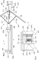
- the Fig. 2 shows part of the nacelle 102 and the Figs. 3 to 5 show different positions of an inverter system 250 of the nacelle 102.
- the Fig. 6 shows an exterior view of the reverser system 250 in the retracted and deployed position, but where only an exterior door 105 is shown diagrammatically by phantom lines.
- the double-flow turbojet 100 has between the nacelle 102 and the engine, a secondary stream 202 in which circulates the secondary flow 208 coming from the air inlet through the fan and which therefore flows in the direction of flow which goes from the front to the rear of the basket 102.
- the nacelle 102 has a fixed structure 206 which is fixedly mounted on the fan housing 206a.
- the inverter system 250 has a movable assembly 207 which comprises a movable cowl 207a forming the walls of the nozzle and a frame 207b.
- the frame 207b here takes the form of a cylinder with perforated walls.
- Movable cowl 207a is attached to and to the rear of frame 207b.
- the movable assembly 207 by means of the frame 207b, is mounted movable in translation in a direction of translation generally parallel to the longitudinal axis X on the fixed structure 206 of the nacelle 102, and more particularly here on the 12 hour beam and the 6 hour beam.
- the translation of the frame 207b, and therefore of the movable assembly 207, is performed by any suitable slide system such as for example slides between the fixed structure 206 and the frame 207b.
- the movable assembly 207, and therefore the frame 207b is movable between an advanced position ( Fig. 3 ) and a retracted position ( Figs. 4 , 5 and 6 ) and vice versa.
- the advanced position the movable assembly 207, and therefore the frame 207b, is positioned as far forward as possible with respect to the longitudinal axis X so that the movable cowl 207a is brought closer to the fan casing 206a.
- the mobile assembly 207, and therefore the frame 207b is positioned as far back as possible with respect to the longitudinal axis X so that the movable cowl 207a is moved rearwardly from the fan casing 206a.
- the movable cowl 207a and the fan casing 206a extend so as to define the outer surface of the secondary duct 202.
- the movable cowl 207a and the fan casing 206a are remote and between them define a window 210 open between the secondary duct 202 and the exterior of the nacelle 102. That is to say that the air from the secondary flow 208 passes through the window 210 to reach the outside of the bypass turbojet 100.
- the fan casing 206a delimits the window 210 forward with respect to the longitudinal axis X and the movable cowl 207a delimits the window 210 behind with respect to the longitudinal axis X.
- the nacelle 102 comprises a plurality of interior doors 104 distributed over the periphery and inside the nacelle 102 according to the angular opening of the window 210 around the longitudinal axis X.
- Each interior door 104 is hingedly mounted on a slide 214 between a stored position ( Figs. 3 and 4 ) and a deployed position ( Fig. 5 ) and vice versa.
- the passage from the stored position to the deployed position is effected by a rotation of the interior door 104 towards the interior of the turbojet 100.
- the articulation takes place along a rear edge of the interior door 104 while the front edge of the interior door 104 moves.
- the stored position of the interior doors 104 can be adopted when the frame 207b is in the forward position or in the retracted position.
- the deployed position of the interior doors 104 can only be adopted when the frame 207b is in the retracted position.
- each interior door 104 closes an area of the perforated part of the frame 207b when the latter is in the advanced position and the same area of the perforated part of the frame 207b and an area of the window 210 when the frame 207b is in position. steephead Valley.
- the interior door 104 does not block said area of the window 210 nor the perforated part of the frame 207b allowing the passage of the secondary flow 208 and the interior door 104 extends towards the motor, that is to say. say across the secondary vein 202.
- each interior door 104 is positioned outside the fan casing 206a and in the deployed position, each interior door 104 is positioned across the secondary stream 202 and deflects at least part of the flow. Secondary flow 208 to the outside through the window 210, the flow is directed forwards with the aid of external doors 105 allowing to produce a counter thrust and described below.
- Each interior door 104 is articulated by its rear edge to the slider 214 on hinges 212 fixed to the slider 214 while the opposite front edge is free and is positioned forward in the stored position and towards the engine in the deployed position.
- the inverter system 250 also comprises for each interior door 104, an exterior door 105.
- the exterior doors 105 are distributed on the periphery and on the exterior of the nacelle 102 according to the angular opening of the window 210 around the. longitudinal axis X.
- the exterior doors 105 are arranged on the exterior with respect to the interior doors 104.
- Each exterior door 105 is mounted opposite an interior door 104 and the exterior door 105 and the interior door 104 facing each other constitute a pair of doors.
- the inverter system 250 thus comprises a plurality of pairs of doors 104, 105 arranged inside the nacelle 102.
- Each outer door 105 is hingedly mounted on the slide 214 between a stored position ( Figs. 3 and 4 ) and a deployed position ( Fig. 5 ) and vice versa.
- the passage from the stored position to the deployed position is effected by a rotation of the outer door 105 outwardly of the turbojet 100.
- the joints of the outer doors 105 are generally opposite the joints of the inner doors 104, as is the case. shown on the Fig. 5 , when the interior doors 104 and the exterior doors 105 are deployed, they generally form a continuity.
- the stored position of the exterior doors 105 can be adopted when the frame 207b is in the forward position or in the retracted position.
- the deployed position can only be adopted when the frame 207b is in the retracted position.
- the deployed position, respectively stored, of the exterior doors 105 is synchronized with the deployed position, respectively stored, of the interior doors 104.
- each outer door 105 closes an area of the perforated part of the frame 207b when the latter is in the advanced position and the same area of the perforated part of the frame 207b and an area of the window 210 when the frame 207b is in position steephead Valley.
- the outer door 105 does not block said zone of the window 210 or the perforated part of the frame 207b and extends outwards from the nacelle 102 allowing the passage of the secondary flow 208.
- each outer door 105 in the stored and advanced position, each outer door 105 is generally in the extension of the movable cowl 207a outside the fan casing 206a and in the deployed position, each outer door 105 opens outwards and deflects the part of the secondary flow 208 which has been previously deflected by the inner doors 104 through the window 210.
- the outer doors 105 are arranged between the movable cowl 207a and the fixed structure 206 so as to constitute an outer wall of the nacelle 102 which is therefore in contact with the air flow which flows around the nacelle. 102.
- Each outer door 105 is articulated by a rear edge to the slider 214 on hinges 213 fixed to the slider 214 while the opposite front edge is free and is positioned forward in the stored position and outward in the deployed position.
- the reversing system 250 therefore has a slide 214 associated with said pair of doors 104, 105.
- the slide 214 is mounted to move in translation in a direction parallel to the direction of translation on the frame 207b.
- the slider 214 is thus movable between a first position which corresponds to the stored position and a second position which corresponds to the deployed position.
- Each door 104, 105 is thus articulated on the slide 214 and is therefore independent of the movable cowl 207 and it is not fixed thereto.
- the passage from the first position to the second position of the slide 214 is mechanically associated with the passage from the stored position to the deployed position of each door 104, 105 and vice versa.
- the reverser system 250 also has, for each slide 214, a first transmission system 216 which is provided to pass the interior door 104 associated with the slide 214, from the stored position to the deployed position. simultaneously, the passage of the slide 214 from the first position to the second position in order to open the interior door 104 and vice versa.
- the reversing system 250 also has, for said slide 214, a second transmission system 217 which is provided to cause the outer door 105 associated with the slide 214 to pass from the stored position to the simultaneously deployed position. of the slide 214 from the first position to the second position in order to open the outer door 105 and vice versa.
- the slider 214 is moved rearward while to reach the second position, the slider 214 is moved forward.
- the translation of the slide 214 on the frame 207b is carried out by any suitable slide system such as, for example, that which is described below.
- the passage from the forward position of the frame 207b to the retracted position of the frame 207b and deployed of the interior doors 104 and of the exterior doors 105 therefore consists, from the forward position of the frame 207b and therefore of the stored positions of the interior 104 and exterior doors 105, to move back the frame 207b by translation relative to the front frame 206 to reach the retracted position for the frame 207b and the stored positions of the interior 104 and exterior 105 doors, then to move each slide 214 from the first position to the second position , that is to say forward, to move the interior doors 104 and the exterior doors 105 from the stored position to the deployed position.
- the nacelle 102 also comprises a set of actuators 218 and 220 ensuring the translational movement of the frame 207b and of the slide 214.
- Each actuator 218, 220 is controlled by a control unit, for example of the processor type, which controls the movements in one way or the other according to the needs of the aircraft 10.
- Each actuator 218, 220 may for example take the form of an electric ball actuator or any other type of suitable actuator.
- the nacelle 102 comprises at least a first actuator 218 fixed in part to the fixed structure 206 of the nacelle 102 and in part to the frame 207b.
- Each first actuator 218 is thus provided to ensure, from the forward position of the frame 207b and therefore from the stored positions of the interior 104 and exterior 105 doors, a translational movement of the frame 207b to the retracted position, and vice versa.
- each slide 214 which is carried by the frame 207b follows the same movement.
- the cylinder of the first actuator 218 is fixed to the fixed structure 206 and the movable rod of the first actuator 218 is fixed to the frame 207b.
- the reversing system 250 comprises, for each slide 214, a second actuator 220 which is fixed for part to the frame 207b and for a part to the slide 214.
- the second actuator 220 is provided to ensure the translational movement of the slide 214 from the first position to the second position.
- the cylinder of the second actuator 220 is fixed to the frame 207b and the movable rod of the second actuator 220 is fixed to the slide 214.
- the second actuator 220 is separate from each first actuator 218 and they can therefore be moved independently of each other.
- the movement of the movable assembly 207 from the advanced position to the retracted position is dissociated from the movement of the doors 104 and 105.
- the Fig. 6 shows an exterior view of the nacelle 102 which shows the slide system between the frame 207b and the slide 214.
- the frame 207b comprises two rods 602 arranged across the window 210 and extending parallel to the direction of translation.
- the slide 214 has a bore in which said rod 602, 604 is fitted, which allows the slide 214 to move along the rods 602 and 604.
- the first transmission system 216 comprises at least a first rod articulated at one end to the interior door 104 and articulated at another end to the movable assembly 207 and more particularly to a part of the frame 207b arranged forward with respect to the articulation of the first rod to the interior door 104.
- the first transmission system 216 comprises two first rods arranged on either side of a median plane of the interior door 104 and passing through the longitudinal axis X.
- the second transmission system 217 comprises at least a second rod articulated at one end to the outer door 105 and articulated by another end to the movable assembly 207 and more particularly to a part of the frame 207b arranged forward with respect to the articulation of the second rod to the exterior door 105.
- the second transmission system 217 comprises two second rods arranged on either side of a median plane of the outer door 105 and passing through the longitudinal axis X as is represented on the Fig. 6 .
- the invention has been more particularly described in the case of a nacelle under a wing, but it can be applied to a nacelle located at the rear of the fuselage.
- the nacelle 102 comprises at least one deflector 226 (if there are several, it is then a cascade-type grid) which is arranged around the secondary stream 202 at the level of the entry window 210, that is to say globally at the level of the zone of passage of the secondary vein 202 to the window 210 in a zone where the flow has the most difficulty to turn to create the reverse thrust (that is to say - say towards the front of the nacelle).
- Each deflector 226 is fixed to the movable assembly 207 of the nacelle 102.
- Each deflector 226 takes the form of a fin which directs the secondary flow 208 towards the window 210 then towards the front of the bypass turbojet 100.
- each deflector 226 in the closed position, is housed in the fixed structure 206 between the outer door 105 and the inner door 104.
- the deflectors 226 are arranged between the rods 602 and 604.
Landscapes
- Engineering & Computer Science (AREA)
- General Engineering & Computer Science (AREA)
- Mechanical Engineering (AREA)
- Aviation & Aerospace Engineering (AREA)
- Chemical & Material Sciences (AREA)
- Combustion & Propulsion (AREA)
- Structures Of Non-Positive Displacement Pumps (AREA)
Description
- La présente invention concerne un turboréacteur double flux qui comporte une nacelle équipée d'un système inverseur comportant des portes extérieures et intérieures, ainsi qu'un aéronef comportant au moins un tel turboréacteur double flux.
- Un aéronef comporte un fuselage de chaque côté duquel est fixée une aile. Sous chaque aile est suspendu au moins un turboréacteur double flux avec une veine secondaire. Chaque turboréacteur double flux est fixé sous l'aile par l'intermédiaire d'un mât qui est fixé entre la structure de l'aile et la structure du turboréacteur double flux.
- Le turboréacteur double flux comporte un moteur et une nacelle qui est fixée autour du moteur pour délimiter entre eux une veine secondaire.
- La nacelle comporte un système inverseur qui comprend une pluralité de portes intérieures, où chacune est mobile entre une position stockée dans laquelle elle est plaquée contre une surface intérieure de la nacelle autour de la veine secondaire, et une position déployée dans laquelle elle est positionnée en travers de la veine secondaire pour diriger le flux secondaire vers une fenêtre dégagée dans la nacelle par le déplacement de la porte intérieure.
- Il est intéressant de pouvoir trouver un système d'inversion de poussée qui soit optimisé et mis en œuvre par un mécanisme simple. La demande de brevet
EP3103995 décrit, à cet effet, un turboréacteur double flux avec un système d'inversion à double porte dans lequel le turboréacteur présente une structure fixe, un actionneur et un ensemble mobile comportant des portes et formant un cadre avec un capot mobile. Pour chaque paire de portes, le turboréacteur comporte un support de rotation solidaire du cadre. Le déploiement des portes consiste à activer l'actionneur pour repousser l'ensemble mobile portant les portes, puis à arrêter le cadre à l'aide d'un frein, puis à continuer d'activer l'actionneur pour repousser un système de transmission de type à bielles pour déployer les portes. - Un objet de la présente invention est de proposer une alternative au système d'inversion à double portes décrit dans la demande de brevet susmentionnée.
- A cet effet, est proposé un turboréacteur double flux tel que revendiqué dans la revendication 1.
- Un tel turboréacteur permet d'optimiser l'inverseur de poussée par la mise en place de portes intérieures et extérieures, de simplifier le mécanisme actionnant le système inverseur et de dissocier le déplacement de l'ensemble mobile du déplacement des portes extérieures et intérieures.
- Les caractéristiques de l'invention mentionnées ci-dessus, ainsi que d'autres, apparaîtront plus clairement à la lecture de la description suivante d'un exemple de réalisation, ladite description étant faite en relation avec les dessins joints, parmi lesquels :
- la
Fig. 1 est une vue de côté d'un aéronef comportant un turboréacteur double flux selon l'invention, - la
Fig. 2 est une vue en perspective et de l'intérieur d'une partie d'une nacelle du turboréacteur double flux selon l'invention, - la
Fig. 3 est une représentation schématique et en coupe d'un système inverseur selon l'invention en position avancée et stockée, - la
Fig. 4 est une représentation similaire à celle de laFig. 3 pour une position intermédiaire correspondant à une position reculée et stockée, - la
Fig. 5 est une représentation similaire à celle de laFig. 3 pour une position reculée et déployée, et - la
Fig. 6 montre une vue extérieure du système inverseur. - Dans la description qui suit, les termes relatifs à une position sont pris en référence au sens d'avancement de l'aéronef et l'écoulement de l'air dans le turboréacteur s'écoule donc de l'avant vers l'arrière de l'aéronef tandis que l'aéronef se déplace vers l'avant.
- La
Fig. 1 montre un aéronef 10 qui comporte un fuselage 12 de chaque côté duquel est fixée une aile 14 qui porte au moins un turboréacteur double flux 100 selon l'invention. La fixation du turboréacteur double flux 100 sous l'aile 14 s'effectue par l'intermédiaire d'un mât 16. - Le turboréacteur double flux 100 présente une nacelle 102, un moteur qui est logé à l'intérieur de la nacelle 102 sous forme d'un noyau et un carter de soufflante 206a en avant de la nacelle 102.
- Dans la description qui suit, et par convention, on appelle X l'axe longitudinal du turboréacteur double flux 100 qui est parallèle à l'axe longitudinal de l'aéronef 10 orienté positivement vers l'avant de l'aéronef 10, on appelle Y l'axe transversal qui est horizontal lorsque l'aéronef est au sol, et Z l'axe vertical, ces trois directions X, Y et Z étant orthogonales entre elles.
- La
Fig. 2 montre une partie de la nacelle 102 et lesFigs. 3 à 5 montrent différentes positions d'un système inverseur 250 de la nacelle 102. LaFig. 6 montre une vue extérieure du système inverseur 250 en position reculée et déployée, mais où seule une porte extérieure 105 est schématisée par des traits mixtes. - Le turboréacteur double flux 100 présente entre la nacelle 102 et le moteur, une veine secondaire 202 dans laquelle circule le flux secondaire 208 provenant de l'entrée d'air à travers la soufflante et qui s'écoule donc selon le sens d'écoulement qui va de l'avant vers l'arrière de la nacelle 102.
- La nacelle 102 présente une structure fixe 206 qui est montée fixe sur le carter de soufflante 206a.
- Le système inverseur 250 présente un ensemble mobile 207 qui comprend un capot mobile 207a formant les parois de la tuyère et un cadre 207b. Le cadre 207b prend ici la forme d'un cylindre à parois ajourées. Le capot mobile 207a est fixé au et à l'arrière du cadre 207b.
- L'ensemble mobile 207, par l'intermédiaire du cadre 207b, est monté mobile en translation selon une direction de translation globalement parallèle à l'axe longitudinal X sur la structure fixe 206 de la nacelle 102, et plus particulièrement ici sur la poutre 12heure et la poutre 6heure.
- La translation du cadre 207b, et donc de l'ensemble mobile 207, est réalisée par tout système de glissière approprié comme par exemple des glissières entre la structure fixe 206 et le cadre 207b.
- L'ensemble mobile 207, et donc le cadre 207b, est mobile entre une position avancée (
Fig. 3 ) et une position reculée (Figs. 4 ,5 et 6 ) et inversement. En position avancée, l'ensemble mobile 207, et donc le cadre 207b, est positionné le plus en avant possible par rapport à l'axe longitudinal X de manière à ce que le capot mobile 207a soit rapproché du carter de soufflante 206a. En position reculée, l'ensemble mobile 207, et donc le cadre 207b, est positionné le plus en arrière possible par rapport à l'axe longitudinal X de manière à ce que le capot mobile 207a soit éloigné vers l'arrière du carter de soufflante 206a. - En position avancée, le capot mobile 207a et le carter de soufflante 206a se prolongent de manière à définir la surface extérieure de la veine secondaire 202.
- En position reculée, le capot mobile 207a et le carter de soufflante 206a sont à distance et définissent entre eux une fenêtre 210 ouverte entre la veine secondaire 202 et l'extérieur de la nacelle 102. C'est-à-dire que l'air provenant du flux secondaire 208 traverse la fenêtre 210 pour rejoindre l'extérieur du turboréacteur double flux 100.
- Le carter de soufflante 206a délimite la fenêtre 210 en avant par rapport à l'axe longitudinal X et le capot mobile 207a délimite la fenêtre 210 en arrière par rapport à l'axe longitudinal X.
- La nacelle 102 comporte une pluralité de portes intérieures 104 réparties sur la périphérie et à l'intérieur de la nacelle 102 en fonction de l'ouverture angulaire de la fenêtre 210 autour de l'axe longitudinal X.
- Chaque porte intérieure 104 est montée articulée sur un coulisseau 214 entre une position stockée (
Figs. 3 et 4 ) et une position déployée (Fig. 5 ) et inversement. Le passage de la position stockée à la position déployée s'effectue par une rotation de la porte intérieure 104 vers l'intérieur du turboréacteur 100. L'articulation s'effectue le long d'un bord arrière de la porte intérieure 104 tandis que le bord avant de la porte intérieure 104 se déplace. - La position stockée des portes intérieures 104 peut être adoptée lorsque le cadre 207b est en position avancée ou en position reculée. La position déployée des portes intérieures 104 ne peut être adoptée que lorsque le cadre 207b est en position reculée.
- En position stockée, chaque porte intérieure 104 obture une zone de la partie ajourée du cadre 207b lorsque ce dernier est en position avancée et la même zone de la partie ajourée du cadre 207b et une zone de la fenêtre 210 lorsque le cadre 207b est en position reculée. En position déployée, la porte intérieure 104 n'obture pas ladite zone de la fenêtre 210 ni la partie ajourée du cadre 207b permettant le passage du flux secondaire 208 et la porte intérieure 104 s'étend vers le moteur, c'est-à-dire en travers de la veine secondaire 202.
- Ainsi, en position stockée et avancée, chaque porte intérieure 104 se positionne à l'extérieur du carter de soufflante 206a et en position déployée, chaque porte intérieure 104 se positionne en travers de la veine secondaire 202 et dévie au moins une partie du flux secondaire 208 vers l'extérieur à travers la fenêtre 210, le flux est orienté vers l'avant à l'aide de portes extérieures 105 permettant de produire une contre-poussée et décrites ci-dessous.
- Chaque porte intérieure 104 est articulée par son bord arrière au coulisseau 214 sur des charnières 212 fixées au coulisseau 214 tandis que le bord avant opposé est libre et se positionne vers l'avant en position stockée et vers le moteur en position déployée.
- Le système inverseur 250 comporte également pour chaque porte intérieure 104, une porte extérieure 105. Les portes extérieures 105 sont réparties sur la périphérie et à l'extérieur de la nacelle 102 en fonction de l'ouverture angulaire de la fenêtre 210 autour de l'axe longitudinal X. Les portes extérieures 105 sont disposées à l'extérieur par rapport aux portes intérieures 104. Chaque porte extérieure 105 est montée en regard d'une porte intérieure 104 et la porte extérieure 105 et la porte intérieure 104 en regard constituent un couple de portes. Le système inverseur 250 comporte ainsi une pluralité de couples de portes 104, 105 disposées à l'intérieur de la nacelle 102.
- Chaque porte extérieure 105 est montée articulée sur le coulisseau 214 entre une position stockée (
Figs. 3 et 4 ) et une position déployée (Fig. 5 ) et inversement. Le passage de la position stockée à la position déployée s'effectue par une rotation de la porte extérieure 105 vers l'extérieur du turboréacteur 100. Les articulations des portes extérieures 105 sont globalement en regard des articulations des portes intérieures 104, ainsi comme cela est montré sur laFig. 5 , lorsque les portes intérieures 104 et les portes extérieures 105 sont déployées, elles forment globalement une continuité. - La position stockée des portes extérieures 105 peut être adoptée lorsque le cadre 207b est en position avancée ou en position reculée. La position déployée ne peut être adoptée que lorsque le cadre 207b est en position reculée. La position déployée, respectivement stockée, des portes extérieures 105 est synchronisée avec la position déployée, respectivement stockée, des portes intérieures 104.
- En position stockée, chaque porte extérieure 105 obture une zone de la partie ajourée du cadre 207b lorsque ce dernier est en position avancée et la même zone de la partie ajourée du cadre 207b et une zone de la fenêtre 210 lorsque le cadre 207b est en position reculée. En position déployée, la porte extérieure 105 n'obture pas ladite zone de la fenêtre 210 ni la partie ajourée du cadre 207b et s'étend vers l'extérieur de la nacelle 102 permettant le passage du flux secondaire 208.
- Ainsi, en position stockée et avancée, chaque porte extérieure 105 est globalement dans le prolongement du capot mobile 207a à l'extérieur du carter de soufflante 206a et en position déployée, chaque porte extérieure 105 s'ouvre vers l'extérieur et dévie la partie du flux secondaire 208 qui a été préalablement déviée par les portes intérieures 104 à travers la fenêtre 210.
- En position stockée, les portes extérieures 105 sont disposées entre le capot mobile 207a et la structure fixe 206 de manière à constituer une paroi extérieure de la nacelle 102 qui est donc en contact avec le flux d'air qui s'écoule autour de la nacelle 102.
- Chaque porte extérieure 105 est articulée par un bord arrière au coulisseau 214 sur des charnières 213 fixées au coulisseau 214 tandis que le bord avant opposé est libre et se positionne vers l'avant en position stockée et vers l'extérieur en position déployée.
- Pour chaque couple de portes 104, 105, le système inverseur 250 présente donc un coulisseau 214 associé audit couple de portes 104, 105. Le coulisseau 214 est monté mobile en translation selon une direction parallèle à la direction de translation sur le cadre 207b. Le coulisseau 214 est ainsi mobile entre une première position qui correspond à la position stockée et une deuxième position qui correspond à la position déployée. Chaque porte 104, 105 est ainsi articulée sur le coulisseau 214 et est donc indépendante du capot mobile 207 et elle n'y est pas fixée.
- Le passage de la première position à la deuxième position du coulisseau 214 est mécaniquement associé au passage de la position stockée à la position déployée de chaque porte 104, 105 et inversement.
- Dans le mode de réalisation particulier présenté ici, le système inverseur 250 présente également, pour chaque coulisseau 214, un premier système de transmission 216 qui est prévu pour faire passer la porte intérieure 104 associée au coulisseau 214, de la position stockée à la position déployée simultanément, au passage du coulisseau 214 de la première position à la deuxième position afin d'ouvrir la porte intérieure 104 et inversement.
- De la même manière, le système inverseur 250 présente également, pour ledit coulisseau 214, un deuxième système de transmission 217 qui est prévu pour faire passer la porte extérieure 105 associée au coulisseau 214, de la position stockée à la position déployée simultanément, au passage du coulisseau 214 de la première position à la deuxième position afin d'ouvrir la porte extérieure 105 et inversement.
- Dans le mode de réalisation de l'invention présenté ici, pour atteindre la première position, le coulisseau 214 est déplacé vers l'arrière tandis que pour atteindre la deuxième position, le coulisseau 214 est déplacé vers l'avant.
- La translation du coulisseau 214 sur le cadre 207b est réalisée par tout système de glissière approprié comme, par exemple, celui qui est décrit ci-dessous.
- Le passage de la position avancée du cadre 207b à la position reculée du cadre 207b et déployée des portes intérieures 104 et des portes extérieures 105 consiste donc, à partir de la position avancée du cadre 207b et donc des positions stockées des portes intérieures 104 et extérieures 105, à reculer le cadre 207b par translation par rapport au cadre avant 206 pour atteindre la position reculée pour le cadre 207b et les positions stockées des portes intérieures 104 et extérieures 105, puis à déplacer chaque coulisseau 214 de la première position à la deuxième position, c'est-à-dire vers l'avant, pour faire passer les portes intérieures 104 et les portes extérieures 105 de la position stockée à la position déployée.
- Le déplacement inverse permet de revenir à la position avancée.
- La nacelle 102 comporte également un ensemble d'actionneurs 218 et 220 assurant le déplacement en translation du cadre 207b et du coulisseau 214. Chaque actionneur 218, 220 est commandé par une unité de contrôle, par exemple du type processeur, qui commande les déplacements dans un sens ou dans l'autre selon les besoins de l'aéronef 10.
- Chaque actionneur 218, 220 peut prendre par exemple la forme d'un vérin électrique à billes ou tout autre type de vérins appropriés.
- Pour assurer le déplacement du cadre 207b, la nacelle 102 comporte au moins un premier actionneur 218 fixé pour une partie à la structure fixe 206 de la nacelle 102 et pour une partie au cadre 207b. Chaque premier actionneur 218 est ainsi prévu pour assurer, à partir de la position avancée du cadre 207b et donc des positions stockées des portes intérieures 104 et extérieures 105, un déplacement en translation du cadre 207b jusqu'à la position reculée, et inversement. Lors du déplacement du cadre 207b, chaque coulisseau 214 qui est porté par le cadre 207b suit le même déplacement.
- Ici, le cylindre du premier actionneur 218 est fixé à la structure fixe 206 et la tige mobile du premier actionneur 218 est fixée au cadre 207b.
- Pour assurer le déplacement de chaque coulisseau 214, et donc de chaque porte intérieure 104 et extérieure 105, le système inverseur 250 comporte, pour chaque coulisseau 214, un deuxième actionneur 220 qui est fixé pour une partie au cadre 207b et pour une partie au coulisseau 214. Le deuxième actionneur 220 est prévu pour assurer le déplacement en translation du coulisseau 214 de la première position à la deuxième position.
- Ici le cylindre du deuxième actionneur 220 est fixé au cadre 207b et la tige mobile du deuxième actionneur 220 est fixée au coulisseau 214.
- Le deuxième actionneur 220 est distinct de chaque premier actionneur 218 et ils peuvent donc être déplacés indépendamment les uns des autres. Le déplacement de l'ensemble mobile 207 de la position avancée à la position reculée est dissocié du déplacement des portes 104 et 105.
- La
Fig. 6 montre une vue extérieure de la nacelle 102 qui montre le système de glissière entre le cadre 207b et le coulisseau 214. - Pour réaliser le système de glissière, le cadre 207b comporte deux tiges 602 disposées en travers de la fenêtre 210 et s'étendant parallèlement à la direction de translation. Pour chaque tige 602, 604, le coulisseau 214 présente un alésage dans lequel est emmanchée ladite tige 602, 604 ce qui permet au coulisseau 214 de se déplacer le long des tiges 602 et 604.
- Le premier système de transmission 216 comporte au moins une première tringle articulée par une extrémité à la porte intérieure 104 et articulée par une autre extrémité à l'ensemble mobile 207 et plus particulièrement à une partie du cadre 207b disposé en avant par rapport à l'articulation de la première tringle à la porte intérieure 104.
- Pour des raisons d'équilibrage, le premier système de transmission 216 comporte deux premières tringles disposées de part et d'autre d'un plan médian de la porte intérieure 104 et passant par l'axe longitudinal X.
- Le deuxième système de transmission 217 comporte au moins une deuxième tringle articulée par une extrémité à la porte extérieure 105 et articulée par une autre extrémité à l'ensemble mobile 207 et plus particulièrement à une partie du cadre 207b disposé en avant par rapport à l'articulation de la deuxième tringle à la porte extérieure 105.
- De la même manière, pour des raisons d'équilibrage, le deuxième système de transmission 217 comporte deux deuxièmes tringles disposées de part et d'autre d'un plan médian de la porte extérieure 105 et passant par l'axe longitudinal X comme cela est représenté sur la
Fig. 6 . - L'invention a été plus particulièrement décrite dans le cas d'une nacelle sous une aile mais elle peut s'appliquer à une nacelle située à l'arrière du fuselage.
- Pour contrôler encore mieux le flux secondaire 208, la nacelle 102 comporte au moins un déflecteur 226 (s'il y en a plusieurs c'est alors une grille de type cascade) qui est disposé autour de la veine secondaire 202 au niveau de l'entrée de la fenêtre 210, c'est-à-dire globalement au niveau de la zone de passage de la veine secondaire 202 à la fenêtre 210 dans une zone où l'écoulement a le plus de mal à tourner pour créer de la poussée inversée (c'est-à-dire vers l'avant de la nacelle).
- Chaque déflecteur 226 est fixé à l'ensemble mobile 207 de la nacelle 102. Chaque déflecteur 226 prend la forme d'un aileron qui oriente le flux secondaire 208 vers la fenêtre 210 puis vers l'avant du turboréacteur double flux 100. Dans le mode de réalisation de l'invention présenté ici, en position de fermeture, chaque déflecteur 226 est logé dans la structure fixe 206 entre la porte extérieure 105 et la porte intérieure 104.
- Dans le mode de réalisation de l'invention présenté à la
Fig. 6 , les déflecteurs 226 sont disposés entre les tiges 602 et 604.
Claims (10)
- Turboréacteur double flux (100) comportant un moteur, une nacelle (102) entourant le moteur et un carter de soufflante, où une veine secondaire (202) d'un flux secondaire (208) est délimitée entre la nacelle (102) et le moteur et dans laquelle un flux d'air circule selon un sens d'écoulement, ladite nacelle (102) comportant :- une structure fixe (206) attachée au carter de soufflante (206a),- un système inverseur (250) présentant :- un ensemble mobile (207) présentant un cadre (207b) et un capot mobile (207a) fixé au cadre (207b), l'ensemble mobile (207) étant mobile en translation sur la structure fixe (206) selon une direction de translation entre une position avancée dans laquelle l'ensemble mobile (207) est positionné de manière à ce que le capot mobile (207a) soit rapproché du carter de soufflante (206a) et une position reculée dans laquelle l'ensemble mobile (207) est positionné de manière à ce que le capot mobile (207a) soit éloigné du carter de soufflante (206a) pour définir entre eux une fenêtre (210) ouverte entre la veine secondaire (202) et l'extérieur de la nacelle (102),- une pluralité de couples de portes, chaque couple étant formé par une porte intérieure (104) et une porte extérieure (105) disposée en regard de la porte intérieure (104),- pour chaque couple de portes (104, 105), un coulisseau (214) monté mobile en translation parallèlement à la direction de translation sur le cadre (207b) entre une première position et une deuxième position,
où chaque porte (104, 105) d'un couple est montée articulée par un bord arrière sur le coulisseau (214) associé, entre une position stockée dans laquelle elle obture une zone de la fenêtre (210) et une position déployée dans laquelle elle n'obture pas ladite zone de la fenêtre (210), les portes intérieures (104) s'étendant vers le moteur en position déployée, les portes extérieures (105) s'étendant vers l'extérieur de la nacelle (102) en position déployée,- pour chaque coulisseau (214), un premier système de transmission (216) prévu pour faire passer la porte intérieure (104) associée au coulisseau (214), de la position stockée à la position déployée simultanément, au passage du coulisseau (214) de la première position à la deuxième position et inversement, et un deuxième système de transmission (217) prévu pour faire passer la porte extérieure (105) associée au coulisseau (214), de la position stockée à la position déployée simultanément au passage du coulisseau (214) de la première position à la deuxième position et inversement, et- au moins un premier actionneur (218) prévu pour assurer le déplacement en translation du cadre (207b) de la position avancée à la position reculée et inversement, et- pour chaque coulisseau (214), un deuxième actionneur (220) fixé en partie au cadre (207b) et prévu pour assurer le déplacement en translation du coulisseau (214) de la première position à la deuxième position et inversement. - Turboréacteur double flux (100) selon la revendication 1, caractérisé en ce que le cadre (207b) comporte deux tiges (602, 604) disposées en travers de la fenêtre (210) et s'étendant parallèlement à la direction de translation, et en ce que pour chaque tige (602, 604), le coulisseau (214) présente un alésage dans lequel est emmanchée ladite tige (602, 604).
- Turboréacteur double flux (100) selon l'une des revendications 1 ou 2, caractérisé en ce que le premier système de transmission (216) comporte au moins une première tringle articulée par une extrémité à la porte intérieure (104) et articulée par une autre extrémité au cadre (207b).
- Turboréacteur double flux (100) selon la revendication 3, caractérisé en ce que le premier système de transmission (216) comporte deux premières tringles disposées de part et d'autre d'un plan médian de la porte intérieure (104).
- Turboréacteur double flux (100) selon l'une des revendications 3 ou 4, caractérisé en ce que l'articulation au niveau du cadre (207b) est disposée en avant par rapport à l'articulation de la première tringle à la porte intérieure (104).
- Turboréacteur double flux (100) selon l'une des revendications 1 à 4, caractérisé en ce que le deuxième système de transmission (217) comporte au moins une deuxième tringle articulée par une extrémité à la porte extérieure (105) et articulée par une autre extrémité au cadre (207b).
- Turboréacteur double flux (100) selon la revendication 6, caractérisé en ce que le deuxième système de transmission (217) comporte deux deuxièmes tringles disposées de part et d'autre d'un plan médian de la porte extérieure (105).
- Turboréacteur double flux (100) selon l'une des revendications 6 ou 7, caractérisé en ce que l'articulation au niveau du cadre (207b) est disposée en avant par rapport à l'articulation de la deuxième tringle à la porte extérieure (105).
- Turboréacteur double flux (100) selon l'une des revendications 1 à 8, caractérisé en ce que les portes extérieures (105) sont disposées entre le capot mobile (207a) et la structure fixe (206) en position stockée de manière à constituer une paroi extérieure de la nacelle (102).
- Aéronef (10) comportant au moins un turboréacteur double flux (100) selon l'une des revendications précédentes.
Applications Claiming Priority (1)
| Application Number | Priority Date | Filing Date | Title |
|---|---|---|---|
| FR1851556A FR3078111B1 (fr) | 2018-02-22 | 2018-02-22 | Turboreacteur comportant une nacelle equipee d'un systeme inverseur comportant des portes exterieures et interieures |
Publications (2)
| Publication Number | Publication Date |
|---|---|
| EP3530925A1 EP3530925A1 (fr) | 2019-08-28 |
| EP3530925B1 true EP3530925B1 (fr) | 2020-12-16 |
Family
ID=61913454
Family Applications (1)
| Application Number | Title | Priority Date | Filing Date |
|---|---|---|---|
| EP19153410.6A Active EP3530925B1 (fr) | 2018-02-22 | 2019-01-24 | Turboreacteur comportant une nacelle equipee d'un systeme inverseur comportant des portes exterieures et interieures |
Country Status (4)
| Country | Link |
|---|---|
| US (1) | US20190257269A1 (fr) |
| EP (1) | EP3530925B1 (fr) |
| CN (1) | CN110182371A (fr) |
| FR (1) | FR3078111B1 (fr) |
Families Citing this family (6)
| Publication number | Priority date | Publication date | Assignee | Title |
|---|---|---|---|---|
| FR3085727A1 (fr) * | 2018-09-06 | 2020-03-13 | Airbus Operations | Turboreacteur comportant une nacelle equipee d'un systeme inverseur comportant des portes interieures et des volets exterieurs |
| FR3092145A1 (fr) * | 2019-01-24 | 2020-07-31 | Airbus Operations | Turboreacteur double flux comportant une serie de lames rotatives pour obturer la veine du flux secondaire |
| US11511874B2 (en) | 2019-09-30 | 2022-11-29 | Rohr, Inc. | Linkage(s) between inner and outer cowl doors |
| EP3798133B1 (fr) | 2019-09-30 | 2023-06-21 | Rohr, Inc. | Liaison supportant une porte d'un système de propulsion d'aéronef |
| FR3105304B1 (fr) * | 2019-12-19 | 2021-12-10 | Safran Nacelles | Inverseur de poussée avec système d’actionnement anti-flambage |
| CN114954906B (zh) * | 2021-02-22 | 2025-08-12 | 中国航发商用航空发动机有限责任公司 | 反推装置和航空发动机短舱 |
Family Cites Families (6)
| Publication number | Priority date | Publication date | Assignee | Title |
|---|---|---|---|---|
| US3815357A (en) * | 1971-01-28 | 1974-06-11 | Rohr Industries Inc | Thrust reversing apparatus |
| RU2044912C1 (ru) * | 1992-11-02 | 1995-09-27 | Акционерное общество открытого типа "Авиадвигатель" | Реверсивное устройство |
| US6845945B1 (en) * | 2001-07-20 | 2005-01-25 | Aircraft Integration Resources, Inc. | Thrust reverser with sliding pivot joints |
| FR2949141B1 (fr) * | 2009-08-14 | 2011-07-15 | Aircelle Sa | Dispositif d'inversion de poussee |
| US10041443B2 (en) * | 2015-06-09 | 2018-08-07 | The Boeing Company | Thrust reverser apparatus and method |
| US10563615B2 (en) * | 2016-05-09 | 2020-02-18 | Mra Systems, Llc | Gas turbine engine with thrust reverser assembly and method of operating |
-
2018
- 2018-02-22 FR FR1851556A patent/FR3078111B1/fr not_active Expired - Fee Related
-
2019
- 2019-01-24 EP EP19153410.6A patent/EP3530925B1/fr active Active
- 2019-02-20 CN CN201910125996.1A patent/CN110182371A/zh active Pending
- 2019-02-20 US US16/280,593 patent/US20190257269A1/en not_active Abandoned
Non-Patent Citations (1)
| Title |
|---|
| None * |
Also Published As
| Publication number | Publication date |
|---|---|
| FR3078111B1 (fr) | 2020-01-17 |
| EP3530925A1 (fr) | 2019-08-28 |
| FR3078111A1 (fr) | 2019-08-23 |
| CN110182371A (zh) | 2019-08-30 |
| US20190257269A1 (en) | 2019-08-22 |
Similar Documents
| Publication | Publication Date | Title |
|---|---|---|
| EP3530925A1 (fr) | Turboreacteur comportant une nacelle equipee d'un systeme inverseur comportant des portes exterieures et interieures | |
| FR3067760B1 (fr) | Turboreacteur comportant une nacelle equipee de volets inverseurs | |
| FR3068394B1 (fr) | Turboreacteur comportant une nacelle equipee de volets inverseurs | |
| EP3715613B1 (fr) | Turboreacteur double flux comportant une serie de lames rotatives pour obturer la veine du flux secondaire | |
| EP3845754B1 (fr) | Turboréacteur double flux comportant un système d'obturation de la veine du flux secondaire comportant un voile | |
| FR3064308A1 (fr) | Turboreacteur comportant une nacelle equipee de volets inverseurs | |
| EP0882881B1 (fr) | Inverseur de poussée de turboréacteur à portes munies d'un becquet mobile à entrainement optimisé | |
| EP3620644B1 (fr) | Turboréacteur comportant une nacelle equipée d'un système inverseur comportant des portes intérieures et des volets extérieurs | |
| EP3667050B1 (fr) | Turboréacteur double flux comportant une série de lames rotatives pour obturer la veine du flux secondaire | |
| EP3726037B1 (fr) | Turboréacteur double flux comportant une série de lames rotatives pour obturer la veine du flux secondaire | |
| FR3057618A1 (fr) | Nacelle d'un turboreacteur comportant un volet inverseur | |
| FR3095015A1 (fr) | Turboreacteur double flux comportant une serie de lames rotatives pour obturer la veine du flux secondaire | |
| EP3845753B1 (fr) | Turboréacteur double flux comportant un système d'obturation de la veine du flux secondaire comportant des voiles | |
| EP3719293B1 (fr) | Turboréacteur comportant une nacelle équipée d'un système inverseur et une grille de cascades mobile | |
| EP3550134B1 (fr) | Turboréacteur comportant une nacelle équipée d'un système inverseur comportant un capot articulé | |
| EP3521604B1 (fr) | Turboreacteur comportant une nacelle equipee d'un systeme inverseur comportant des portes | |
| FR3074854A1 (fr) | Turboreacteur comportant une nacelle equipee d'un systeme inverseur comportant des portes | |
| EP3530571A1 (fr) | Nacelle equipee d'un systeme inverseur comportant des portes et des systemes anti-vibration des portes en position stockee | |
| EP3543139B1 (fr) | Nacelle equipee d'un systeme inverseur comportant des portes et des systemes de verrouillage des portes en position stockee | |
| FR3077606A1 (fr) | Nacelle d'un turboreacteur comportant une porte exterieure d'inversion | |
| FR3108151A1 (fr) | Turboreacteur double flux comportant une serie de lames rotatives pour obturer la veine du flux secondaire et devier le flux d’air | |
| FR3104211A1 (fr) | Turboreacteur double flux comportant une serie de lames rotatives pour obturer la veine du flux secondaire | |
| FR3124229A1 (fr) | Turboréacteur double flux comportant une série de lames rotatives pour obturer la veine du flux secondaire | |
| FR3108684A1 (fr) | Turboreacteur double flux comportant des deflecteurs mobiles | |
| EP4607020A1 (fr) | Turboréacteur comportant une nacelle équipée de volets inverseurs |
Legal Events
| Date | Code | Title | Description |
|---|---|---|---|
| STAA | Information on the status of an ep patent application or granted ep patent |
Free format text: STATUS: EXAMINATION IS IN PROGRESS |
|
| PUAI | Public reference made under article 153(3) epc to a published international application that has entered the european phase |
Free format text: ORIGINAL CODE: 0009012 |
|
| 17P | Request for examination filed |
Effective date: 20190124 |
|
| AK | Designated contracting states |
Kind code of ref document: A1 Designated state(s): AL AT BE BG CH CY CZ DE DK EE ES FI FR GB GR HR HU IE IS IT LI LT LU LV MC MK MT NL NO PL PT RO RS SE SI SK SM TR |
|
| AX | Request for extension of the european patent |
Extension state: BA ME |
|
| RBV | Designated contracting states (corrected) |
Designated state(s): AL AT BE BG CH CY CZ DE DK EE ES FI FR GB GR HR HU IE IS IT LI LT LU LV MC MK MT NL NO PL PT RO RS SE SI SK SM TR |
|
| GRAP | Despatch of communication of intention to grant a patent |
Free format text: ORIGINAL CODE: EPIDOSNIGR1 |
|
| STAA | Information on the status of an ep patent application or granted ep patent |
Free format text: STATUS: GRANT OF PATENT IS INTENDED |
|
| INTG | Intention to grant announced |
Effective date: 20200811 |
|
| GRAS | Grant fee paid |
Free format text: ORIGINAL CODE: EPIDOSNIGR3 |
|
| GRAA | (expected) grant |
Free format text: ORIGINAL CODE: 0009210 |
|
| STAA | Information on the status of an ep patent application or granted ep patent |
Free format text: STATUS: THE PATENT HAS BEEN GRANTED |
|
| AK | Designated contracting states |
Kind code of ref document: B1 Designated state(s): AL AT BE BG CH CY CZ DE DK EE ES FI FR GB GR HR HU IE IS IT LI LT LU LV MC MK MT NL NO PL PT RO RS SE SI SK SM TR |
|
| REG | Reference to a national code |
Ref country code: GB Ref legal event code: FG4D Free format text: NOT ENGLISH |
|
| REG | Reference to a national code |
Ref country code: DE Ref legal event code: R096 Ref document number: 602019001683 Country of ref document: DE |
|
| REG | Reference to a national code |
Ref country code: IE Ref legal event code: FG4D Free format text: LANGUAGE OF EP DOCUMENT: FRENCH |
|
| REG | Reference to a national code |
Ref country code: AT Ref legal event code: REF Ref document number: 1345823 Country of ref document: AT Kind code of ref document: T Effective date: 20210115 |
|
| PG25 | Lapsed in a contracting state [announced via postgrant information from national office to epo] |
Ref country code: GR Free format text: LAPSE BECAUSE OF FAILURE TO SUBMIT A TRANSLATION OF THE DESCRIPTION OR TO PAY THE FEE WITHIN THE PRESCRIBED TIME-LIMIT Effective date: 20210317 Ref country code: NO Free format text: LAPSE BECAUSE OF FAILURE TO SUBMIT A TRANSLATION OF THE DESCRIPTION OR TO PAY THE FEE WITHIN THE PRESCRIBED TIME-LIMIT Effective date: 20210316 Ref country code: FI Free format text: LAPSE BECAUSE OF FAILURE TO SUBMIT A TRANSLATION OF THE DESCRIPTION OR TO PAY THE FEE WITHIN THE PRESCRIBED TIME-LIMIT Effective date: 20201216 Ref country code: RS Free format text: LAPSE BECAUSE OF FAILURE TO SUBMIT A TRANSLATION OF THE DESCRIPTION OR TO PAY THE FEE WITHIN THE PRESCRIBED TIME-LIMIT Effective date: 20201216 |
|
| REG | Reference to a national code |
Ref country code: AT Ref legal event code: MK05 Ref document number: 1345823 Country of ref document: AT Kind code of ref document: T Effective date: 20201216 |
|
| REG | Reference to a national code |
Ref country code: NL Ref legal event code: MP Effective date: 20201216 |
|
| PG25 | Lapsed in a contracting state [announced via postgrant information from national office to epo] |
Ref country code: LV Free format text: LAPSE BECAUSE OF FAILURE TO SUBMIT A TRANSLATION OF THE DESCRIPTION OR TO PAY THE FEE WITHIN THE PRESCRIBED TIME-LIMIT Effective date: 20201216 Ref country code: SE Free format text: LAPSE BECAUSE OF FAILURE TO SUBMIT A TRANSLATION OF THE DESCRIPTION OR TO PAY THE FEE WITHIN THE PRESCRIBED TIME-LIMIT Effective date: 20201216 Ref country code: BG Free format text: LAPSE BECAUSE OF FAILURE TO SUBMIT A TRANSLATION OF THE DESCRIPTION OR TO PAY THE FEE WITHIN THE PRESCRIBED TIME-LIMIT Effective date: 20210316 |
|
| PG25 | Lapsed in a contracting state [announced via postgrant information from national office to epo] |
Ref country code: NL Free format text: LAPSE BECAUSE OF FAILURE TO SUBMIT A TRANSLATION OF THE DESCRIPTION OR TO PAY THE FEE WITHIN THE PRESCRIBED TIME-LIMIT Effective date: 20201216 Ref country code: HR Free format text: LAPSE BECAUSE OF FAILURE TO SUBMIT A TRANSLATION OF THE DESCRIPTION OR TO PAY THE FEE WITHIN THE PRESCRIBED TIME-LIMIT Effective date: 20201216 |
|
| REG | Reference to a national code |
Ref country code: LT Ref legal event code: MG9D |
|
| PG25 | Lapsed in a contracting state [announced via postgrant information from national office to epo] |
Ref country code: LT Free format text: LAPSE BECAUSE OF FAILURE TO SUBMIT A TRANSLATION OF THE DESCRIPTION OR TO PAY THE FEE WITHIN THE PRESCRIBED TIME-LIMIT Effective date: 20201216 Ref country code: PT Free format text: LAPSE BECAUSE OF FAILURE TO SUBMIT A TRANSLATION OF THE DESCRIPTION OR TO PAY THE FEE WITHIN THE PRESCRIBED TIME-LIMIT Effective date: 20210416 Ref country code: RO Free format text: LAPSE BECAUSE OF FAILURE TO SUBMIT A TRANSLATION OF THE DESCRIPTION OR TO PAY THE FEE WITHIN THE PRESCRIBED TIME-LIMIT Effective date: 20201216 Ref country code: CZ Free format text: LAPSE BECAUSE OF FAILURE TO SUBMIT A TRANSLATION OF THE DESCRIPTION OR TO PAY THE FEE WITHIN THE PRESCRIBED TIME-LIMIT Effective date: 20201216 Ref country code: EE Free format text: LAPSE BECAUSE OF FAILURE TO SUBMIT A TRANSLATION OF THE DESCRIPTION OR TO PAY THE FEE WITHIN THE PRESCRIBED TIME-LIMIT Effective date: 20201216 Ref country code: SK Free format text: LAPSE BECAUSE OF FAILURE TO SUBMIT A TRANSLATION OF THE DESCRIPTION OR TO PAY THE FEE WITHIN THE PRESCRIBED TIME-LIMIT Effective date: 20201216 Ref country code: SM Free format text: LAPSE BECAUSE OF FAILURE TO SUBMIT A TRANSLATION OF THE DESCRIPTION OR TO PAY THE FEE WITHIN THE PRESCRIBED TIME-LIMIT Effective date: 20201216 |
|
| PG25 | Lapsed in a contracting state [announced via postgrant information from national office to epo] |
Ref country code: AT Free format text: LAPSE BECAUSE OF FAILURE TO SUBMIT A TRANSLATION OF THE DESCRIPTION OR TO PAY THE FEE WITHIN THE PRESCRIBED TIME-LIMIT Effective date: 20201216 Ref country code: PL Free format text: LAPSE BECAUSE OF FAILURE TO SUBMIT A TRANSLATION OF THE DESCRIPTION OR TO PAY THE FEE WITHIN THE PRESCRIBED TIME-LIMIT Effective date: 20201216 |
|
| REG | Reference to a national code |
Ref country code: DE Ref legal event code: R097 Ref document number: 602019001683 Country of ref document: DE |
|
| PG25 | Lapsed in a contracting state [announced via postgrant information from national office to epo] |
Ref country code: LU Free format text: LAPSE BECAUSE OF NON-PAYMENT OF DUE FEES Effective date: 20210124 Ref country code: MC Free format text: LAPSE BECAUSE OF FAILURE TO SUBMIT A TRANSLATION OF THE DESCRIPTION OR TO PAY THE FEE WITHIN THE PRESCRIBED TIME-LIMIT Effective date: 20201216 Ref country code: IS Free format text: LAPSE BECAUSE OF FAILURE TO SUBMIT A TRANSLATION OF THE DESCRIPTION OR TO PAY THE FEE WITHIN THE PRESCRIBED TIME-LIMIT Effective date: 20210416 |
|
| REG | Reference to a national code |
Ref country code: BE Ref legal event code: MM Effective date: 20210131 |
|
| PLBE | No opposition filed within time limit |
Free format text: ORIGINAL CODE: 0009261 |
|
| STAA | Information on the status of an ep patent application or granted ep patent |
Free format text: STATUS: NO OPPOSITION FILED WITHIN TIME LIMIT |
|
| PG25 | Lapsed in a contracting state [announced via postgrant information from national office to epo] |
Ref country code: AL Free format text: LAPSE BECAUSE OF FAILURE TO SUBMIT A TRANSLATION OF THE DESCRIPTION OR TO PAY THE FEE WITHIN THE PRESCRIBED TIME-LIMIT Effective date: 20201216 Ref country code: IT Free format text: LAPSE BECAUSE OF FAILURE TO SUBMIT A TRANSLATION OF THE DESCRIPTION OR TO PAY THE FEE WITHIN THE PRESCRIBED TIME-LIMIT Effective date: 20201216 |
|
| 26N | No opposition filed |
Effective date: 20210917 |
|
| PG25 | Lapsed in a contracting state [announced via postgrant information from national office to epo] |
Ref country code: DK Free format text: LAPSE BECAUSE OF FAILURE TO SUBMIT A TRANSLATION OF THE DESCRIPTION OR TO PAY THE FEE WITHIN THE PRESCRIBED TIME-LIMIT Effective date: 20201216 |
|
| PG25 | Lapsed in a contracting state [announced via postgrant information from national office to epo] |
Ref country code: ES Free format text: LAPSE BECAUSE OF FAILURE TO SUBMIT A TRANSLATION OF THE DESCRIPTION OR TO PAY THE FEE WITHIN THE PRESCRIBED TIME-LIMIT Effective date: 20201216 Ref country code: IE Free format text: LAPSE BECAUSE OF NON-PAYMENT OF DUE FEES Effective date: 20210124 |
|
| PG25 | Lapsed in a contracting state [announced via postgrant information from national office to epo] |
Ref country code: SI Free format text: LAPSE BECAUSE OF FAILURE TO SUBMIT A TRANSLATION OF THE DESCRIPTION OR TO PAY THE FEE WITHIN THE PRESCRIBED TIME-LIMIT Effective date: 20201216 |
|
| PG25 | Lapsed in a contracting state [announced via postgrant information from national office to epo] |
Ref country code: IS Free format text: LAPSE BECAUSE OF FAILURE TO SUBMIT A TRANSLATION OF THE DESCRIPTION OR TO PAY THE FEE WITHIN THE PRESCRIBED TIME-LIMIT Effective date: 20210416 |
|
| PG25 | Lapsed in a contracting state [announced via postgrant information from national office to epo] |
Ref country code: BE Free format text: LAPSE BECAUSE OF NON-PAYMENT OF DUE FEES Effective date: 20210131 |
|
| REG | Reference to a national code |
Ref country code: CH Ref legal event code: PL |
|
| PG25 | Lapsed in a contracting state [announced via postgrant information from national office to epo] |
Ref country code: LI Free format text: LAPSE BECAUSE OF NON-PAYMENT OF DUE FEES Effective date: 20220131 Ref country code: CH Free format text: LAPSE BECAUSE OF NON-PAYMENT OF DUE FEES Effective date: 20220131 |
|
| PG25 | Lapsed in a contracting state [announced via postgrant information from national office to epo] |
Ref country code: CY Free format text: LAPSE BECAUSE OF FAILURE TO SUBMIT A TRANSLATION OF THE DESCRIPTION OR TO PAY THE FEE WITHIN THE PRESCRIBED TIME-LIMIT Effective date: 20201216 |
|
| PG25 | Lapsed in a contracting state [announced via postgrant information from national office to epo] |
Ref country code: HU Free format text: LAPSE BECAUSE OF FAILURE TO SUBMIT A TRANSLATION OF THE DESCRIPTION OR TO PAY THE FEE WITHIN THE PRESCRIBED TIME-LIMIT; INVALID AB INITIO Effective date: 20190124 |
|
| PG25 | Lapsed in a contracting state [announced via postgrant information from national office to epo] |
Ref country code: MK Free format text: LAPSE BECAUSE OF FAILURE TO SUBMIT A TRANSLATION OF THE DESCRIPTION OR TO PAY THE FEE WITHIN THE PRESCRIBED TIME-LIMIT Effective date: 20201216 |
|
| PG25 | Lapsed in a contracting state [announced via postgrant information from national office to epo] |
Ref country code: MT Free format text: LAPSE BECAUSE OF FAILURE TO SUBMIT A TRANSLATION OF THE DESCRIPTION OR TO PAY THE FEE WITHIN THE PRESCRIBED TIME-LIMIT Effective date: 20201216 |
|
| PG25 | Lapsed in a contracting state [announced via postgrant information from national office to epo] |
Ref country code: TR Free format text: LAPSE BECAUSE OF FAILURE TO SUBMIT A TRANSLATION OF THE DESCRIPTION OR TO PAY THE FEE WITHIN THE PRESCRIBED TIME-LIMIT Effective date: 20201216 |
|
| PGFP | Annual fee paid to national office [announced via postgrant information from national office to epo] |
Ref country code: GB Payment date: 20260123 Year of fee payment: 8 |
|
| PGFP | Annual fee paid to national office [announced via postgrant information from national office to epo] |
Ref country code: DE Payment date: 20260121 Year of fee payment: 8 |
|
| PGFP | Annual fee paid to national office [announced via postgrant information from national office to epo] |
Ref country code: FR Payment date: 20260123 Year of fee payment: 8 |