EP3530923B1 - Method of pre-heating a internal combustion engine by oil and jacket water cooler - Google Patents
Method of pre-heating a internal combustion engine by oil and jacket water cooler Download PDFInfo
- Publication number
- EP3530923B1 EP3530923B1 EP18157808.9A EP18157808A EP3530923B1 EP 3530923 B1 EP3530923 B1 EP 3530923B1 EP 18157808 A EP18157808 A EP 18157808A EP 3530923 B1 EP3530923 B1 EP 3530923B1
- Authority
- EP
- European Patent Office
- Prior art keywords
- internal combustion
- combustion engine
- cooling
- during
- starting operation
- Prior art date
- Legal status (The legal status is an assumption and is not a legal conclusion. Google has not performed a legal analysis and makes no representation as to the accuracy of the status listed.)
- Active
Links
Images

Classifications
-
- F—MECHANICAL ENGINEERING; LIGHTING; HEATING; WEAPONS; BLASTING
- F01—MACHINES OR ENGINES IN GENERAL; ENGINE PLANTS IN GENERAL; STEAM ENGINES
- F01P—COOLING OF MACHINES OR ENGINES IN GENERAL; COOLING OF INTERNAL-COMBUSTION ENGINES
- F01P5/00—Pumping cooling-air or liquid coolants
- F01P5/10—Pumping liquid coolant; Arrangements of coolant pumps
- F01P5/12—Pump-driving arrangements
-
- F—MECHANICAL ENGINEERING; LIGHTING; HEATING; WEAPONS; BLASTING
- F02—COMBUSTION ENGINES; HOT-GAS OR COMBUSTION-PRODUCT ENGINE PLANTS
- F02G—HOT GAS OR COMBUSTION-PRODUCT POSITIVE-DISPLACEMENT ENGINE PLANTS; USE OF WASTE HEAT OF COMBUSTION ENGINES; NOT OTHERWISE PROVIDED FOR
- F02G5/00—Profiting from waste heat of combustion engines, not otherwise provided for
-
- F—MECHANICAL ENGINEERING; LIGHTING; HEATING; WEAPONS; BLASTING
- F01—MACHINES OR ENGINES IN GENERAL; ENGINE PLANTS IN GENERAL; STEAM ENGINES
- F01M—LUBRICATING OF MACHINES OR ENGINES IN GENERAL; LUBRICATING INTERNAL COMBUSTION ENGINES; CRANKCASE VENTILATING
- F01M5/00—Heating, cooling, or controlling temperature of lubricant; Lubrication means facilitating engine starting
- F01M5/02—Conditioning lubricant for aiding engine starting, e.g. heating
-
- F—MECHANICAL ENGINEERING; LIGHTING; HEATING; WEAPONS; BLASTING
- F01—MACHINES OR ENGINES IN GENERAL; ENGINE PLANTS IN GENERAL; STEAM ENGINES
- F01M—LUBRICATING OF MACHINES OR ENGINES IN GENERAL; LUBRICATING INTERNAL COMBUSTION ENGINES; CRANKCASE VENTILATING
- F01M5/00—Heating, cooling, or controlling temperature of lubricant; Lubrication means facilitating engine starting
- F01M5/02—Conditioning lubricant for aiding engine starting, e.g. heating
- F01M5/021—Conditioning lubricant for aiding engine starting, e.g. heating by heating
-
- F—MECHANICAL ENGINEERING; LIGHTING; HEATING; WEAPONS; BLASTING
- F01—MACHINES OR ENGINES IN GENERAL; ENGINE PLANTS IN GENERAL; STEAM ENGINES
- F01P—COOLING OF MACHINES OR ENGINES IN GENERAL; COOLING OF INTERNAL-COMBUSTION ENGINES
- F01P3/00—Liquid cooling
- F01P3/20—Cooling circuits not specific to a single part of engine or machine
-
- F—MECHANICAL ENGINEERING; LIGHTING; HEATING; WEAPONS; BLASTING
- F02—COMBUSTION ENGINES; HOT-GAS OR COMBUSTION-PRODUCT ENGINE PLANTS
- F02N—STARTING OF COMBUSTION ENGINES; STARTING AIDS FOR SUCH ENGINES, NOT OTHERWISE PROVIDED FOR
- F02N19/00—Starting aids for combustion engines, not otherwise provided for
- F02N19/02—Aiding engine start by thermal means, e.g. using lighted wicks
- F02N19/04—Aiding engine start by thermal means, e.g. using lighted wicks by heating of fluids used in engines
- F02N19/10—Aiding engine start by thermal means, e.g. using lighted wicks by heating of fluids used in engines by heating of engine coolants
-
- F—MECHANICAL ENGINEERING; LIGHTING; HEATING; WEAPONS; BLASTING
- F01—MACHINES OR ENGINES IN GENERAL; ENGINE PLANTS IN GENERAL; STEAM ENGINES
- F01P—COOLING OF MACHINES OR ENGINES IN GENERAL; COOLING OF INTERNAL-COMBUSTION ENGINES
- F01P5/00—Pumping cooling-air or liquid coolants
- F01P5/10—Pumping liquid coolant; Arrangements of coolant pumps
- F01P5/12—Pump-driving arrangements
- F01P2005/125—Driving auxiliary pumps electrically
-
- F—MECHANICAL ENGINEERING; LIGHTING; HEATING; WEAPONS; BLASTING
- F01—MACHINES OR ENGINES IN GENERAL; ENGINE PLANTS IN GENERAL; STEAM ENGINES
- F01P—COOLING OF MACHINES OR ENGINES IN GENERAL; COOLING OF INTERNAL-COMBUSTION ENGINES
- F01P2031/00—Fail safe
- F01P2031/30—Cooling after the engine is stopped
-
- F—MECHANICAL ENGINEERING; LIGHTING; HEATING; WEAPONS; BLASTING
- F01—MACHINES OR ENGINES IN GENERAL; ENGINE PLANTS IN GENERAL; STEAM ENGINES
- F01P—COOLING OF MACHINES OR ENGINES IN GENERAL; COOLING OF INTERNAL-COMBUSTION ENGINES
- F01P2060/00—Cooling circuits using auxiliaries
- F01P2060/02—Intercooler
-
- F—MECHANICAL ENGINEERING; LIGHTING; HEATING; WEAPONS; BLASTING
- F01—MACHINES OR ENGINES IN GENERAL; ENGINE PLANTS IN GENERAL; STEAM ENGINES
- F01P—COOLING OF MACHINES OR ENGINES IN GENERAL; COOLING OF INTERNAL-COMBUSTION ENGINES
- F01P2060/00—Cooling circuits using auxiliaries
- F01P2060/12—Turbo charger
-
- F—MECHANICAL ENGINEERING; LIGHTING; HEATING; WEAPONS; BLASTING
- F01—MACHINES OR ENGINES IN GENERAL; ENGINE PLANTS IN GENERAL; STEAM ENGINES
- F01P—COOLING OF MACHINES OR ENGINES IN GENERAL; COOLING OF INTERNAL-COMBUSTION ENGINES
- F01P2060/00—Cooling circuits using auxiliaries
- F01P2060/18—Heater
-
- F—MECHANICAL ENGINEERING; LIGHTING; HEATING; WEAPONS; BLASTING
- F01—MACHINES OR ENGINES IN GENERAL; ENGINE PLANTS IN GENERAL; STEAM ENGINES
- F01P—COOLING OF MACHINES OR ENGINES IN GENERAL; COOLING OF INTERNAL-COMBUSTION ENGINES
- F01P7/00—Controlling of coolant flow
- F01P7/02—Controlling of coolant flow the coolant being cooling-air
- F01P7/04—Controlling of coolant flow the coolant being cooling-air by varying pump speed, e.g. by changing pump-drive gear ratio
- F01P7/048—Controlling of coolant flow the coolant being cooling-air by varying pump speed, e.g. by changing pump-drive gear ratio using electrical drives
-
- F—MECHANICAL ENGINEERING; LIGHTING; HEATING; WEAPONS; BLASTING
- F02—COMBUSTION ENGINES; HOT-GAS OR COMBUSTION-PRODUCT ENGINE PLANTS
- F02B—INTERNAL-COMBUSTION PISTON ENGINES; COMBUSTION ENGINES IN GENERAL
- F02B29/00—Engines characterised by provision for charging or scavenging not provided for in groups F02B25/00, F02B27/00 or F02B33/00 - F02B39/00; Details thereof
- F02B29/04—Cooling of air intake supply
- F02B29/0406—Layout of the intake air cooling or coolant circuit
- F02B29/0437—Liquid cooled heat exchangers
- F02B29/0443—Layout of the coolant or refrigerant circuit
-
- Y—GENERAL TAGGING OF NEW TECHNOLOGICAL DEVELOPMENTS; GENERAL TAGGING OF CROSS-SECTIONAL TECHNOLOGIES SPANNING OVER SEVERAL SECTIONS OF THE IPC; TECHNICAL SUBJECTS COVERED BY FORMER USPC CROSS-REFERENCE ART COLLECTIONS [XRACs] AND DIGESTS
- Y02—TECHNOLOGIES OR APPLICATIONS FOR MITIGATION OR ADAPTATION AGAINST CLIMATE CHANGE
- Y02T—CLIMATE CHANGE MITIGATION TECHNOLOGIES RELATED TO TRANSPORTATION
- Y02T10/00—Road transport of goods or passengers
- Y02T10/10—Internal combustion engine [ICE] based vehicles
- Y02T10/12—Improving ICE efficiencies
Definitions
- the invention concerns an internal combustion engine having the features of the classifying portion of claim 1 and a method for pre-heating an internal combustion engine having the features of the classifying portion of claim 6.
- Internal combustion engines known in the state of the art comprise a cooling device, which is used for cooling the internal combustion engine during and/or after operation of the internal combustion engine.
- these cooling devices comprise heat exchangers, which heat exchangers exchange heat between an operational liquid (coming from the internal combustion engine) and cooling medium.
- the operational liquid could for example be a cooling water of a cooling water circuit, which cooling water circuit cools cylinders or other components of the internal combustion engine during operation or oil used to lubricate moving parts of the internal combustion engine.
- the cooling medium can vary depending on the field of application of the internal combustion engine.
- a frequently used cooling medium is water, which in a water circuit transports thermal energy away from the internal combustion engine.
- the cooling medium has a lower temperature level than the operational liquid of the internal combustion engine.
- pre-heating devices can comprise, for example, electrical pre-heaters or plate heat exchangers. Cooling fluid or operational liquid of the internal combustion engine is led through the pre-heating devices before and/or during the starting operation of the internal combustion engine by use of an externally driven pump (not driven by the internal combustion engine).
- a disadvantage of such a procedure is that a lot of energy is required for the heating of the pre-heating device, especially if electrical heating devices are used.
- a further disadvantage is the high costs for providing such pre-heating devices.
- the purpose of the invention is to provide an internal combustion engine and a method for pre-heating an internal combustion engine, wherein manufacturing and/or operating costs are reduced.
- a starting operation of the internal combustion engine extends from actuating a starting switch to reach a pre-defined operation state of the internal combustion engine, e.g. reaching nominal rotational speed of the internal combustion engine.
- the cooling device is configured to pre-heat the internal combustion engine, wherein heat is exchanged by the heat exchanger between the at least one operational liquid and the cooling medium, which cooling medium has before and/or during the starting operation of the internal combustion engine a higher temperature level than the at least one operational liquid of the internal combustion engine.
- thermal energy carried by the cooling medium can be used for pre-heating the internal combustion engine. It is not necessary to generate additional thermal energy at the place of the internal combustion engine.
- the thermal level of the cooling medium which during operation (after finishing the stating operation) is low enough for cooling the internal combustion engine, is high enough before/or during a starting operation to pre-heat the internal combustion engine. No further components for heating are necessary. This reduces the costs of manufacturing an internal combustion engine.
- Such an engine is known for example from WO2017110900 A1 .
- At least one further cooling device is provided for at least one external component of the internal combustion engine, wherein the at least one further cooling device is configured to heat the at least one further component of the internal combustion engine before and/or during a starting operation of the internal combustion engine.
- an external component of the internal combustion engine for example a turbo charger and/or an intercooler and/or a fuel cooler can be pre-heated.
- the internal combustion engine is a stationary reciprocating piston engine preferably driving a generator, which generator could provide a power supply network with electrically energy.
- At least one pump - preferably an electrical pump - is provided, wherein the pump is configured to pump at least one operational liquid to and from the at least one cooling device before and/or during a starting operation of the internal combustion engine.
- the at least one pump can be driven independently from the internal combustion engine, so that the at least one pump could start to work before the internal combustion engine is started. This could for example be done by providing an electrical pump.
- the at least one pump can be provided at a bypass line, wherein the bypass line can be fluidically connected to the at least one heat exchanger before and/or during a starting operation of the internal combustion engine.
- the pump for pre-heating is used only before and/or during the starting operation of the internal combustion engine in connection with the heat exchanger.
- the bypass line can be closed and the pump (which could be switched off after starting the internal combustion engine) does not form an obstacle for the circulation of the at least one operational liquid.
- the pumping of the at least one operation liquid can be done by a further pump which is driven by the internal combustion engine.
- At least two cooling devices can be provided for cooling at least one operational liquid of the internal combustion engine, wherein a first of the at least two cooling devices is configured to cool at least one cooling water circuit of the internal combustion engine and wherein a second of the at least two cooling devices is configured to cool at least one oil circuit of the internal combustion engine, wherein the at least one cooling water circuit and the at least one oil circuit of the internal combustion engine can be heated by the at least two cooling devices before and/or during a starting operation of the internal combustion engine.
- the internal combustion engine comprises at least one cooling device for cooling at least one operational liquid of the internal combustion engine during and/or after operation of the internal combustion engine by an cooling medium, wherein the cooling medium has during the operation of the internal combustion engine a lower temperature level than the at least one operational liquid of the internal combustion engine, wherein the at least one cooling device is used before and/or during a starting operation of the internal combustion engine to pre-heat the internal combustion engine by an cooling medium, wherein the cooling medium has before and/or during the starting operation of the internal combustion engine a higher temperature level than the at least one operational liquid of the internal combustion engine, wherein at least one further cooling device is configured to heat at least one further component of the internal combustion engine before and/or during a starting operation of the internal combustion engine.
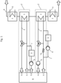
- Fig. 1 shows an internal combustion engine 1 having a cooling device 2 as known from the state of the art. More particularly, the internal combustion engine 1 shown in Fig. 1 has two cooling devices 2.
- cooling water of the internal combustion engine 1 can be led from the internal combustion engine 1 (connection point 4.1) to a heat exchanger 3 and from the heat exchanger 3 back to the internal combustion engine 1 (to the connection point 4.2 of the internal combustion engine 1).
- a pump 6 is provided in the line 4 leading the cooling water circuit of the internal combustion engine 1 back to the internal combustion engine 1, which pump 6 is driven by the internal combustion engine 1 and keeps the cooling water circuit during the operation of the internal combustion engine 1 in motion.
- oil of the internal combustion engine 1 can be led from the internal combustion engine 1 (connection point 5.1) to a heat exchanger 3 and from the heat exchanger 3 back to the internal combustion engine 1 (to the connection point 5.3 of the internal combustion engine 1).
- two heat exchangers 3 are provided for a line 10 and a line 11, which lines 10 and 11 could for example be used to cool external components of the internal combustion engine (i.e. a turbo charger or an intercooler).
- the heat exchangers 3 exchange heat with the line 8, which line 8 is provided for guiding a cooling medium. This cooling medium is used to remove heat from the internal combustion engine 1.
- the removed heat of the internal combustion engine 1 can be used - for example - by a thermal power plant.
- bypass lines 7 arranged parallel to the lines 4, 5.
- Those bypass lines 7 include at least one pump 6 and at least one pre-heating device 9.
- a check valve 12 is arranged in the line 4 of the cooling water circuit to ensure a flow direction of the cooling water circuit during a bypass operation during a pre-heating of the internal combustion engine 1.
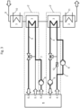
- Fig. 2 shows an internal combustion engine 1 according to the state of the art (the same internal combustion engine 1 as shown in Fig. 1 ) during a pre-heating operation, which can be done before and/or during a starting operation of the internal combustion engine 1.
- the flow of the oil and the cooling water can be redirected through pre-heating devices 9.
- the cooling water is lead through a bypass line 7, which bypass line comprises a pump 6 and a pre-heating device 9.
- the pump 6 is driven by an independent drive (not shown in the figures), because usually during a pre-heating operation the internal combustion engine 1 is not active and therefore a separate pump 6 with an independent drive is necessary to move the cooling water circuit.
- the pre-heating device 9 could for example be an electrical heating device. After flowing through the bypass line 7 the cooling water is led back to the internal combustion engine 1 (to the connection point 4.2 of the internal combustion engine 1) by a further bypass line, which bypass line bypasses the heat exchanger 3.
- the oil is lead flowing from a connecting point 5.2 of the internal combustion engine (for example a connecting point to the crankcase of the internal combustion engine 1) to a pump 6 - which is also driven by an independent drive - to a pre-heating device 9 for oil and after flowing through this pre-heating device 9 back to the internal combustion engine (to the connection point 5.3 of the internal combustion engine 1) by the use of a bypass line, wherein the heat exchanger 3 can be bypassed.
- the flow of the oil and the cooling water during a pre-heating operation of the internal combustion engine 1 is shown by the thick lines of Fig. 2 .
- Fig. 3 shows an embodiment of an internal combustion engine 1 according to the invention during a pre-heating operation, wherein during and/or before a starting operation of the internal combustion engine 1 the cooling device 2 is configured to pre-heat the internal combustion engine 1, wherein heat is exchanged by the heat exchanger 3 between the operational liquid and a cooling medium. More specific, the embodiment of Fig. 3 shows a pre-heating of the internal combustion engine 1 during and/or before a starting operation of the internal combustion engine 1, wherein heat is provided from the cooling medium in line 8 to the cooling water in line 4 as well as from the cooling medium in line 8 to the oil circuit in line 5 by the heat exchangers 3. This is possible because the cooling medium in line 8 has a higher temperature level before and/or during the starting operation of the internal combustion engine 1 than the cooling water and the oil in lines 4, 5.
- the oil circuit is driven during the pre-heating operation by a pump 6 arranged in a bypass line 7, which pump 6 is driven independently from the internal combustion engine 1 and is provided downstream of the connecting point 5.2.
- the cooling water circuit is driven during the pre-heating operation by a pump 6, which pump 6 is driven independently from the internal combustion engine 1 and is provided in the bypass line 7.
- the bypass line 7, which comprises the pump 6, can be bypassed after the starting operation during an operation of the internal combustion engine 1 by the cooling water circuit in line 4.
- further external components of the internal combustion engine 1 can be pre-heated by the heat exchangers 3 and the lines 10 and 11.
- the sequence in which the cooling medium passes through the heat exchangers of the lines 4, 5, 10, 11 can be individually changed.
Landscapes
- Engineering & Computer Science (AREA)
- Mechanical Engineering (AREA)
- General Engineering & Computer Science (AREA)
- Chemical & Material Sciences (AREA)
- Combustion & Propulsion (AREA)
- Lubrication Of Internal Combustion Engines (AREA)
Description
- The invention concerns an internal combustion engine having the features of the classifying portion of
claim 1 and a method for pre-heating an internal combustion engine having the features of the classifying portion ofclaim 6. - Internal combustion engines known in the state of the art comprise a cooling device, which is used for cooling the internal combustion engine during and/or after operation of the internal combustion engine. Frequently, these cooling devices comprise heat exchangers, which heat exchangers exchange heat between an operational liquid (coming from the internal combustion engine) and cooling medium. The operational liquid could for example be a cooling water of a cooling water circuit, which cooling water circuit cools cylinders or other components of the internal combustion engine during operation or oil used to lubricate moving parts of the internal combustion engine. For the transport of the operational liquid between the internal combustion engine and the heat exchanger lines are provided. The cooling medium can vary depending on the field of application of the internal combustion engine. A frequently used cooling medium is water, which in a water circuit transports thermal energy away from the internal combustion engine. For cooling the internal combustion engine during operation the cooling medium has a lower temperature level than the operational liquid of the internal combustion engine.
- As known from the state of the art internal combustion engines have to be pre-heated before starting. A pre-heating before starting of the internal combustion engine reduces thermal stress of the internal combustion engine, which would occur if the internal combustion engine would not be pre-heated before starting. This thermal stress may result in defects of components, either immediately or after a certain period of time, wherein the lifetime of a component would be reduced significantly. Additionally the cold start behavior of the engine is improved, if the temperature of the operational liquids (such as cooling liquid, oil, fuel or air) is increased relatively to cold ambient air.
- It is commonly known to provide internal combustion engines with pre-heating devices. Such pre-heating devices can comprise, for example, electrical pre-heaters or plate heat exchangers. Cooling fluid or operational liquid of the internal combustion engine is led through the pre-heating devices before and/or during the starting operation of the internal combustion engine by use of an externally driven pump (not driven by the internal combustion engine).
- A disadvantage of such a procedure is that a lot of energy is required for the heating of the pre-heating device, especially if electrical heating devices are used. A further disadvantage is the high costs for providing such pre-heating devices.
- The purpose of the invention is to provide an internal combustion engine and a method for pre-heating an internal combustion engine, wherein manufacturing and/or operating costs are reduced.
- This is being achieved by an internal combustion engine having the features of
claim 1 and a method for pre-heating an internal combustion engine having the features ofclaim 6. - A starting operation of the internal combustion engine extends from actuating a starting switch to reach a pre-defined operation state of the internal combustion engine, e.g. reaching nominal rotational speed of the internal combustion engine.
- According to the invention it is provided that during and/or before a starting operation of the internal combustion engine the cooling device is configured to pre-heat the internal combustion engine, wherein heat is exchanged by the heat exchanger between the at least one operational liquid and the cooling medium, which cooling medium has before and/or during the starting operation of the internal combustion engine a higher temperature level than the at least one operational liquid of the internal combustion engine.
- In this way, according to the invention already existing thermal energy carried by the cooling medium can be used for pre-heating the internal combustion engine. It is not necessary to generate additional thermal energy at the place of the internal combustion engine. The thermal level of the cooling medium, which during operation (after finishing the stating operation) is low enough for cooling the internal combustion engine, is high enough before/or during a starting operation to pre-heat the internal combustion engine. No further components for heating are necessary. This reduces the costs of manufacturing an internal combustion engine.
- Such an engine is known for example from
WO2017110900 A1 . - Furthermore, according to the invention, at least one further cooling device is provided for at least one external component of the internal combustion engine, wherein the at least one further cooling device is configured to heat the at least one further component of the internal combustion engine before and/or during a starting operation of the internal combustion engine. In this way, an external component of the internal combustion engine, for example a turbo charger and/or an intercooler and/or a fuel cooler can be pre-heated.
- Embodiments of the invention are defined by the dependent claims.
- Preferably it can be provided that the internal combustion engine is a stationary reciprocating piston engine preferably driving a generator, which generator could provide a power supply network with electrically energy.
- In an embodiment of the invention at least one pump - preferably an electrical pump - is provided, wherein the pump is configured to pump at least one operational liquid to and from the at least one cooling device before and/or during a starting operation of the internal combustion engine. Advantageously it can be provided that the at least one pump can be driven independently from the internal combustion engine, so that the at least one pump could start to work before the internal combustion engine is started. This could for example be done by providing an electrical pump. Furthermore the at least one pump can be provided at a bypass line, wherein the bypass line can be fluidically connected to the at least one heat exchanger before and/or during a starting operation of the internal combustion engine. By such an embodiment it can be provided that the pump for pre-heating is used only before and/or during the starting operation of the internal combustion engine in connection with the heat exchanger. After pre-heating the bypass line can be closed and the pump (which could be switched off after starting the internal combustion engine) does not form an obstacle for the circulation of the at least one operational liquid. During the operation of the internal combustion engine the pumping of the at least one operation liquid can be done by a further pump which is driven by the internal combustion engine.
- Additionally or alternatively at least two cooling devices can be provided for cooling at least one operational liquid of the internal combustion engine, wherein a first of the at least two cooling devices is configured to cool at least one cooling water circuit of the internal combustion engine and wherein a second of the at least two cooling devices is configured to cool at least one oil circuit of the internal combustion engine, wherein the at least one cooling water circuit and the at least one oil circuit of the internal combustion engine can be heated by the at least two cooling devices before and/or during a starting operation of the internal combustion engine.
- Protection is also sought for a method for pre-heating an internal combustion engine, wherein the internal combustion engine comprises at least one cooling device for cooling at least one operational liquid of the internal combustion engine during and/or after operation of the internal combustion engine by an cooling medium, wherein the cooling medium has during the operation of the internal combustion engine a lower temperature level than the at least one operational liquid of the internal combustion engine, wherein the at least one cooling device is used before and/or during a starting operation of the internal combustion engine to pre-heat the internal combustion engine by an cooling medium, wherein the cooling medium has before and/or during the starting operation of the internal combustion engine a higher temperature level than the at least one operational liquid of the internal combustion engine, wherein at least one further cooling device is configured to heat at least one further component of the internal combustion engine before and/or during a starting operation of the internal combustion engine.
- Further details and advantages of the present invention will be described with reference to the specific description hereinafter. In the drawing:
- Fig. 1
- shows an embodiment of an internal combustion engine having a cooling device as known from the state of the art,
- Fig. 2
- shows an embodiment of an internal combustion engine having a cooling device as shown in the state of the art during pre-heating, and
- Fig. 3
- shows an embodiment of an internal combustion engine according to the invention.
-
Fig. 1 shows aninternal combustion engine 1 having acooling device 2 as known from the state of the art. More particularly, theinternal combustion engine 1 shown inFig. 1 has twocooling devices 2. By theline 4 cooling water of theinternal combustion engine 1 can be led from the internal combustion engine 1 (connection point 4.1) to aheat exchanger 3 and from theheat exchanger 3 back to the internal combustion engine 1 (to the connection point 4.2 of the internal combustion engine 1). Apump 6 is provided in theline 4 leading the cooling water circuit of theinternal combustion engine 1 back to theinternal combustion engine 1, whichpump 6 is driven by theinternal combustion engine 1 and keeps the cooling water circuit during the operation of theinternal combustion engine 1 in motion. By usingline 5 oil of theinternal combustion engine 1 can be led from the internal combustion engine 1 (connection point 5.1) to aheat exchanger 3 and from theheat exchanger 3 back to the internal combustion engine 1 (to the connection point 5.3 of the internal combustion engine 1). Furthermore, twoheat exchangers 3 are provided for aline 10 and aline 11, whichlines heat exchangers 3 exchange heat with theline 8, whichline 8 is provided for guiding a cooling medium. This cooling medium is used to remove heat from theinternal combustion engine 1. The removed heat of theinternal combustion engine 1 can be used - for example - by a thermal power plant. The flow directions of the circuits throughlines bypass lines 7 arranged parallel to thelines bypass lines 7 include at least onepump 6 and at least one pre-heatingdevice 9. Acheck valve 12 is arranged in theline 4 of the cooling water circuit to ensure a flow direction of the cooling water circuit during a bypass operation during a pre-heating of theinternal combustion engine 1. -
Fig. 2 shows aninternal combustion engine 1 according to the state of the art (the sameinternal combustion engine 1 as shown inFig. 1 ) during a pre-heating operation, which can be done before and/or during a starting operation of theinternal combustion engine 1. During the pre-heating of theinternal combustion engine 1 the flow of the oil and the cooling water can be redirected through pre-heatingdevices 9. In more detail, during a pre-heating operation the cooling water is lead through abypass line 7, which bypass line comprises apump 6 and apre-heating device 9. Thepump 6 is driven by an independent drive (not shown in the figures), because usually during a pre-heating operation theinternal combustion engine 1 is not active and therefore aseparate pump 6 with an independent drive is necessary to move the cooling water circuit. Thepre-heating device 9 could for example be an electrical heating device. After flowing through thebypass line 7 the cooling water is led back to the internal combustion engine 1 (to the connection point 4.2 of the internal combustion engine 1) by a further bypass line, which bypass line bypasses theheat exchanger 3. During a pre-heating operation of theinternal combustion engine 1 the oil is lead flowing from a connecting point 5.2 of the internal combustion engine (for example a connecting point to the crankcase of the internal combustion engine 1) to a pump 6 - which is also driven by an independent drive - to apre-heating device 9 for oil and after flowing through thispre-heating device 9 back to the internal combustion engine (to the connection point 5.3 of the internal combustion engine 1) by the use of a bypass line, wherein theheat exchanger 3 can be bypassed. The flow of the oil and the cooling water during a pre-heating operation of theinternal combustion engine 1 is shown by the thick lines ofFig. 2 . -
Fig. 3 shows an embodiment of aninternal combustion engine 1 according to the invention during a pre-heating operation, wherein during and/or before a starting operation of theinternal combustion engine 1 thecooling device 2 is configured to pre-heat theinternal combustion engine 1, wherein heat is exchanged by theheat exchanger 3 between the operational liquid and a cooling medium. More specific, the embodiment ofFig. 3 shows a pre-heating of theinternal combustion engine 1 during and/or before a starting operation of theinternal combustion engine 1, wherein heat is provided from the cooling medium inline 8 to the cooling water inline 4 as well as from the cooling medium inline 8 to the oil circuit inline 5 by theheat exchangers 3. This is possible because the cooling medium inline 8 has a higher temperature level before and/or during the starting operation of theinternal combustion engine 1 than the cooling water and the oil inlines - The oil circuit is driven during the pre-heating operation by a
pump 6 arranged in abypass line 7, which pump 6 is driven independently from theinternal combustion engine 1 and is provided downstream of the connecting point 5.2. The cooling water circuit is driven during the pre-heating operation by apump 6, which pump 6 is driven independently from theinternal combustion engine 1 and is provided in thebypass line 7. Thebypass line 7, which comprises thepump 6, can be bypassed after the starting operation during an operation of theinternal combustion engine 1 by the cooling water circuit inline 4. Also, further external components of theinternal combustion engine 1 can be pre-heated by theheat exchangers 3 and thelines lines
Claims (6)
- An internal combustion engine (1), comprising at least one cooling device (2) for cooling at least one operational liquid of the internal combustion engine (1) during and/or after operation of the internal combustion engine (1), wherein the at least one cooling device (2) has at least one heat exchanger (3) and lines (4, 5) for transporting the at least one operational liquid to and from the at least one heat exchanger (3), wherein the heat exchanger (3) exchanges heat with a cooling medium, which cooling medium has during the operation of the internal combustion engine (1) a lower temperature level than the at least one operational liquid of the internal combustion engine (1), wherein during and/or before a starting operation of the internal combustion engine (1) the cooling device (2) is configured to pre-heat the internal combustion engine (1), wherein heat is exchanged by the heat exchanger (3) between the at least one operational liquid and the cooling medium, which cooling medium has before and/or during a starting operation of the internal combustion engine (1) a higher temperature level than the at least one operational liquid of the internal combustion engine (1), characterized in that at least one further cooling device (2) is provided for at least one external component of the internal combustion engine (1), wherein the at least one further cooling device (2) is configured to heat the at least one further component of the internal combustion engine (1) before and/or during a starting operation of the internal combustion engine (1).
- Internal combustion engine as set forth in claim 1, characterised in that at least one pump (6) - preferably an electrical pump - is provided, wherein the pump (6) is configured to pump at least one operational liquid to and from the at least one cooling device (2) before and/or during a starting operation of the internal combustion engine (1).
- Internal combustion engine as set forth in claim 2, characterised in that the at least one pump (6) is provided at a bypass line (7), wherein the bypass line (7) can be fluidically connected to the at least one heat exchanger (3) before and/or during a starting operation of the internal combustion engine (1).
- Internal combustion engine as set forth in at least one of the preceding claims, characterised in that at least two cooling devices (2) are provided for cooling the at least one operational liquid of the internal combustion engine (1), wherein a first of the at least two cooling devices (2) is configured to cool at least one cooling water circuit of the internal combustion engine (1) and wherein a second of the at least two cooling devices (2) is configured to cool at least one oil circuit of the internal combustion engine (1), wherein the at least one cooling water circuit and the at least one oil circuit of the internal combustion engine (1) can be heated by the at least two cooling devices (2) before and/or during a starting operation of the internal combustion engine (1).
- Internal combustion engine as set forth in at least one of the preceding claims, characterised in that the at least one external component of the internal combustion engine (1) is a turbo charger and/or an intercooler and/or a fuel cooler.
- A method for pre-heating an internal combustion engine, wherein the internal combustion engine (1) comprises at least one cooling device (2) for cooling at least one operational liquid of the internal combustion engine (1) during and/or after operation of the internal combustion engine by an cooling medium, wherein the cooling medium has during the operation of the internal combustion engine (1) a lower temperature level than the at least one operational liquid of the internal combustion engine (1), wherein the at least one cooling device (2) is used before and/or during a starting operation of the internal combustion engine (1) to pre-heat the internal combustion engine (1) by an cooling medium, wherein the cooling medium has before and/or during the starting operation of the internal combustion engine (1) a higher temperature level than the at least one operational liquid of the internal combustion engine (1), characterized in that at least one further cooling device (2) is used before and/or during a starting operation of the internal combustion engine (1) to pre-heat at least one further component of the internal combustion engine (1) by an cooling medium.
Priority Applications (3)
| Application Number | Priority Date | Filing Date | Title |
|---|---|---|---|
| EP18157808.9A EP3530923B1 (en) | 2018-02-21 | 2018-02-21 | Method of pre-heating a internal combustion engine by oil and jacket water cooler |
| US16/273,313 US10767545B2 (en) | 2018-02-21 | 2019-02-12 | Method of pre-heating a internal combustion engine by oil and jacket water cooler |
| CN201910129336.0A CN110173384A (en) | 2018-02-21 | 2019-02-21 | The method for preheating internal combustion engine by oil and collet water cooler |
Applications Claiming Priority (1)
| Application Number | Priority Date | Filing Date | Title |
|---|---|---|---|
| EP18157808.9A EP3530923B1 (en) | 2018-02-21 | 2018-02-21 | Method of pre-heating a internal combustion engine by oil and jacket water cooler |
Publications (2)
| Publication Number | Publication Date |
|---|---|
| EP3530923A1 EP3530923A1 (en) | 2019-08-28 |
| EP3530923B1 true EP3530923B1 (en) | 2024-04-24 |
Family
ID=61256654
Family Applications (1)
| Application Number | Title | Priority Date | Filing Date |
|---|---|---|---|
| EP18157808.9A Active EP3530923B1 (en) | 2018-02-21 | 2018-02-21 | Method of pre-heating a internal combustion engine by oil and jacket water cooler |
Country Status (3)
| Country | Link |
|---|---|
| US (1) | US10767545B2 (en) |
| EP (1) | EP3530923B1 (en) |
| CN (1) | CN110173384A (en) |
Family Cites Families (17)
| Publication number | Priority date | Publication date | Assignee | Title |
|---|---|---|---|---|
| US2993487A (en) * | 1959-02-04 | 1961-07-25 | Maschf Augsburg Nuernberg Ag | Starting device for internal combustion engine |
| FR1475778A (en) * | 1966-02-03 | 1967-04-07 | Improvements to supercharged diesel engines | |
| US4700047A (en) * | 1986-05-23 | 1987-10-13 | Crossett & Sons, Inc. | Fuel preheater for diesel engines |
| JP2001132539A (en) * | 1999-11-01 | 2001-05-15 | Honda Motor Co Ltd | Engine exhaust heat recovery device |
| GB2472228B (en) * | 2009-07-29 | 2016-01-27 | Ford Global Tech Llc | A method for reducing the fuel consumption of an engine |
| US8020538B2 (en) * | 2010-05-28 | 2011-09-20 | Ford Global Technologies, Llc | Cooled EGR system for coolant heating during cold engine start |
| CN201896657U (en) * | 2010-12-09 | 2011-07-13 | 奇瑞汽车股份有限公司 | Water cooling system of engine |
| CN103388507B (en) * | 2012-05-10 | 2016-10-05 | 安徽华菱汽车有限公司 | A kind of engine |
| JP6135256B2 (en) * | 2012-05-23 | 2017-05-31 | 株式会社デンソー | Thermal management system for vehicles |
| CN103306852A (en) * | 2013-06-21 | 2013-09-18 | 高志男 | Waste heat recycle device for automobile cooling water |
| CN103291426B (en) * | 2013-06-21 | 2015-08-26 | 高志男 | A kind of waste heat recovery device of vehicle exhaust |
| CN203383888U (en) * | 2013-06-21 | 2014-01-08 | 高志男 | Waste heat recycling device for automobile exhaust |
| KR101945823B1 (en) * | 2013-12-10 | 2019-02-11 | 한온시스템 주식회사 | Heat exchanger with combined functions in vehicles |
| JP6265171B2 (en) * | 2015-06-09 | 2018-01-24 | トヨタ自動車株式会社 | Vehicle heat exchange device |
| JP6225949B2 (en) * | 2015-06-23 | 2017-11-08 | トヨタ自動車株式会社 | Cooling device for internal combustion engine |
| CN105134359B (en) * | 2015-10-16 | 2017-12-26 | 安徽江淮汽车集团股份有限公司 | A kind of engine-cooling system using delay circulation stream |
| WO2017110900A1 (en) * | 2015-12-21 | 2017-06-29 | 大阪瓦斯株式会社 | Heat supply system |
-
2018
- 2018-02-21 EP EP18157808.9A patent/EP3530923B1/en active Active
-
2019
- 2019-02-12 US US16/273,313 patent/US10767545B2/en active Active
- 2019-02-21 CN CN201910129336.0A patent/CN110173384A/en active Pending
Also Published As
| Publication number | Publication date |
|---|---|
| CN110173384A (en) | 2019-08-27 |
| EP3530923A1 (en) | 2019-08-28 |
| US10767545B2 (en) | 2020-09-08 |
| US20190257239A1 (en) | 2019-08-22 |
Similar Documents
| Publication | Publication Date | Title |
|---|---|---|
| US11588379B2 (en) | Arrangement for cooling an electric machine in a motor vehicle, and method for operating the arrangement | |
| US6601545B1 (en) | Method and device for transporting heat energy that is produced in a motor vehicle | |
| US8464668B2 (en) | Vehicle cooling system with directed flows | |
| US8196385B2 (en) | Turbomachine control system | |
| US8037872B2 (en) | Engine system having cooled and heated inlet air | |
| US11125139B2 (en) | Waste heat recovery vehicle cooling optimization | |
| US8109242B2 (en) | Multi-thermostat engine cooling system | |
| CN108343500B (en) | automobile engine cooling system | |
| US20140311141A1 (en) | Waste heat utilization apparatus | |
| CN108979785B (en) | Oil circulation device for internal combustion engine | |
| ZA200608218B (en) | Cooling system for a vehicle | |
| US7886705B2 (en) | Engine system having dedicated thermal management system | |
| RU2010104018A (en) | COOLING SYSTEM FOR INTERNAL COMBUSTION ENGINE | |
| CN111071028A (en) | Transmission unit comprising an internal combustion engine and an electric motor, and method for operating such a transmission unit | |
| US20130051912A1 (en) | Construction machine with oil-cooled generator | |
| US20140352296A1 (en) | Method and apparatus for operating an internal combustion engine | |
| US20040187505A1 (en) | Integrated cooling system | |
| RU155350U1 (en) | INTERNAL COMBUSTION ENGINE WITH LIQUID COOLING WITH SECONDARY CIRCUIT | |
| EP3530923B1 (en) | Method of pre-heating a internal combustion engine by oil and jacket water cooler | |
| US10781741B2 (en) | Cooling system after engine shut-down, cylinder head, and method for operating a cooling system after engine shut-down | |
| CN107532500A (en) | Coolant circuits for liquid cooled transmissions | |
| JP5760775B2 (en) | Cooling device for internal combustion engine | |
| KR20020081326A (en) | Cooling system for a motor vehicle | |
| JP5760774B2 (en) | Cooling device for internal combustion engine | |
| JP2012132379A (en) | Engine cooling water device |
Legal Events
| Date | Code | Title | Description |
|---|---|---|---|
| PUAI | Public reference made under article 153(3) epc to a published international application that has entered the european phase |
Free format text: ORIGINAL CODE: 0009012 |
|
| STAA | Information on the status of an ep patent application or granted ep patent |
Free format text: STATUS: THE APPLICATION HAS BEEN PUBLISHED |
|
| AK | Designated contracting states |
Kind code of ref document: A1 Designated state(s): AL AT BE BG CH CY CZ DE DK EE ES FI FR GB GR HR HU IE IS IT LI LT LU LV MC MK MT NL NO PL PT RO RS SE SI SK SM TR |
|
| AX | Request for extension of the european patent |
Extension state: BA ME |
|
| STAA | Information on the status of an ep patent application or granted ep patent |
Free format text: STATUS: REQUEST FOR EXAMINATION WAS MADE |
|
| 17P | Request for examination filed |
Effective date: 20200228 |
|
| RBV | Designated contracting states (corrected) |
Designated state(s): AL AT BE BG CH CY CZ DE DK EE ES FI FR GB GR HR HU IE IS IT LI LT LU LV MC MK MT NL NO PL PT RO RS SE SI SK SM TR |
|
| STAA | Information on the status of an ep patent application or granted ep patent |
Free format text: STATUS: EXAMINATION IS IN PROGRESS |
|
| 17Q | First examination report despatched |
Effective date: 20211110 |
|
| P01 | Opt-out of the competence of the unified patent court (upc) registered |
Effective date: 20230614 |
|
| GRAP | Despatch of communication of intention to grant a patent |
Free format text: ORIGINAL CODE: EPIDOSNIGR1 |
|
| STAA | Information on the status of an ep patent application or granted ep patent |
Free format text: STATUS: GRANT OF PATENT IS INTENDED |
|
| INTG | Intention to grant announced |
Effective date: 20240102 |
|
| GRAS | Grant fee paid |
Free format text: ORIGINAL CODE: EPIDOSNIGR3 |
|
| GRAA | (expected) grant |
Free format text: ORIGINAL CODE: 0009210 |
|
| STAA | Information on the status of an ep patent application or granted ep patent |
Free format text: STATUS: THE PATENT HAS BEEN GRANTED |
|
| AK | Designated contracting states |
Kind code of ref document: B1 Designated state(s): AL AT BE BG CH CY CZ DE DK EE ES FI FR GB GR HR HU IE IS IT LI LT LU LV MC MK MT NL NO PL PT RO RS SE SI SK SM TR |
|
| REG | Reference to a national code |
Ref country code: GB Ref legal event code: FG4D |
|
| REG | Reference to a national code |
Ref country code: CH Ref legal event code: EP |
|
| REG | Reference to a national code |
Ref country code: DE Ref legal event code: R096 Ref document number: 602018068439 Country of ref document: DE |
|
| REG | Reference to a national code |
Ref country code: IE Ref legal event code: FG4D |
|
| REG | Reference to a national code |
Ref country code: LT Ref legal event code: MG9D |
|
| REG | Reference to a national code |
Ref country code: NL Ref legal event code: MP Effective date: 20240424 |
|
| REG | Reference to a national code |
Ref country code: AT Ref legal event code: MK05 Ref document number: 1679829 Country of ref document: AT Kind code of ref document: T Effective date: 20240424 |
|
| PG25 | Lapsed in a contracting state [announced via postgrant information from national office to epo] |
Ref country code: NL Free format text: LAPSE BECAUSE OF FAILURE TO SUBMIT A TRANSLATION OF THE DESCRIPTION OR TO PAY THE FEE WITHIN THE PRESCRIBED TIME-LIMIT Effective date: 20240424 |
|
| PG25 | Lapsed in a contracting state [announced via postgrant information from national office to epo] |
Ref country code: NL Free format text: LAPSE BECAUSE OF FAILURE TO SUBMIT A TRANSLATION OF THE DESCRIPTION OR TO PAY THE FEE WITHIN THE PRESCRIBED TIME-LIMIT Effective date: 20240424 |
|
| PG25 | Lapsed in a contracting state [announced via postgrant information from national office to epo] |
Ref country code: IS Free format text: LAPSE BECAUSE OF FAILURE TO SUBMIT A TRANSLATION OF THE DESCRIPTION OR TO PAY THE FEE WITHIN THE PRESCRIBED TIME-LIMIT Effective date: 20240824 |
|
| PG25 | Lapsed in a contracting state [announced via postgrant information from national office to epo] |
Ref country code: BG Free format text: LAPSE BECAUSE OF FAILURE TO SUBMIT A TRANSLATION OF THE DESCRIPTION OR TO PAY THE FEE WITHIN THE PRESCRIBED TIME-LIMIT Effective date: 20240424 |
|
| PG25 | Lapsed in a contracting state [announced via postgrant information from national office to epo] |
Ref country code: HR Free format text: LAPSE BECAUSE OF FAILURE TO SUBMIT A TRANSLATION OF THE DESCRIPTION OR TO PAY THE FEE WITHIN THE PRESCRIBED TIME-LIMIT Effective date: 20240424 Ref country code: FI Free format text: LAPSE BECAUSE OF FAILURE TO SUBMIT A TRANSLATION OF THE DESCRIPTION OR TO PAY THE FEE WITHIN THE PRESCRIBED TIME-LIMIT Effective date: 20240424 |
|
| PG25 | Lapsed in a contracting state [announced via postgrant information from national office to epo] |
Ref country code: GR Free format text: LAPSE BECAUSE OF FAILURE TO SUBMIT A TRANSLATION OF THE DESCRIPTION OR TO PAY THE FEE WITHIN THE PRESCRIBED TIME-LIMIT Effective date: 20240725 |
|
| PG25 | Lapsed in a contracting state [announced via postgrant information from national office to epo] |
Ref country code: PT Free format text: LAPSE BECAUSE OF FAILURE TO SUBMIT A TRANSLATION OF THE DESCRIPTION OR TO PAY THE FEE WITHIN THE PRESCRIBED TIME-LIMIT Effective date: 20240826 |
|
| PG25 | Lapsed in a contracting state [announced via postgrant information from national office to epo] |
Ref country code: ES Free format text: LAPSE BECAUSE OF FAILURE TO SUBMIT A TRANSLATION OF THE DESCRIPTION OR TO PAY THE FEE WITHIN THE PRESCRIBED TIME-LIMIT Effective date: 20240424 |
|
| PG25 | Lapsed in a contracting state [announced via postgrant information from national office to epo] |
Ref country code: AT Free format text: LAPSE BECAUSE OF FAILURE TO SUBMIT A TRANSLATION OF THE DESCRIPTION OR TO PAY THE FEE WITHIN THE PRESCRIBED TIME-LIMIT Effective date: 20240424 |
|
| PG25 | Lapsed in a contracting state [announced via postgrant information from national office to epo] |
Ref country code: PL Free format text: LAPSE BECAUSE OF FAILURE TO SUBMIT A TRANSLATION OF THE DESCRIPTION OR TO PAY THE FEE WITHIN THE PRESCRIBED TIME-LIMIT Effective date: 20240424 |
|
| PG25 | Lapsed in a contracting state [announced via postgrant information from national office to epo] |
Ref country code: LV Free format text: LAPSE BECAUSE OF FAILURE TO SUBMIT A TRANSLATION OF THE DESCRIPTION OR TO PAY THE FEE WITHIN THE PRESCRIBED TIME-LIMIT Effective date: 20240424 |
|
| PG25 | Lapsed in a contracting state [announced via postgrant information from national office to epo] |
Ref country code: PT Free format text: LAPSE BECAUSE OF FAILURE TO SUBMIT A TRANSLATION OF THE DESCRIPTION OR TO PAY THE FEE WITHIN THE PRESCRIBED TIME-LIMIT Effective date: 20240826 Ref country code: PL Free format text: LAPSE BECAUSE OF FAILURE TO SUBMIT A TRANSLATION OF THE DESCRIPTION OR TO PAY THE FEE WITHIN THE PRESCRIBED TIME-LIMIT Effective date: 20240424 Ref country code: NO Free format text: LAPSE BECAUSE OF FAILURE TO SUBMIT A TRANSLATION OF THE DESCRIPTION OR TO PAY THE FEE WITHIN THE PRESCRIBED TIME-LIMIT Effective date: 20240724 Ref country code: LV Free format text: LAPSE BECAUSE OF FAILURE TO SUBMIT A TRANSLATION OF THE DESCRIPTION OR TO PAY THE FEE WITHIN THE PRESCRIBED TIME-LIMIT Effective date: 20240424 Ref country code: IS Free format text: LAPSE BECAUSE OF FAILURE TO SUBMIT A TRANSLATION OF THE DESCRIPTION OR TO PAY THE FEE WITHIN THE PRESCRIBED TIME-LIMIT Effective date: 20240824 Ref country code: HR Free format text: LAPSE BECAUSE OF FAILURE TO SUBMIT A TRANSLATION OF THE DESCRIPTION OR TO PAY THE FEE WITHIN THE PRESCRIBED TIME-LIMIT Effective date: 20240424 Ref country code: GR Free format text: LAPSE BECAUSE OF FAILURE TO SUBMIT A TRANSLATION OF THE DESCRIPTION OR TO PAY THE FEE WITHIN THE PRESCRIBED TIME-LIMIT Effective date: 20240725 Ref country code: FI Free format text: LAPSE BECAUSE OF FAILURE TO SUBMIT A TRANSLATION OF THE DESCRIPTION OR TO PAY THE FEE WITHIN THE PRESCRIBED TIME-LIMIT Effective date: 20240424 Ref country code: ES Free format text: LAPSE BECAUSE OF FAILURE TO SUBMIT A TRANSLATION OF THE DESCRIPTION OR TO PAY THE FEE WITHIN THE PRESCRIBED TIME-LIMIT Effective date: 20240424 Ref country code: BG Free format text: LAPSE BECAUSE OF FAILURE TO SUBMIT A TRANSLATION OF THE DESCRIPTION OR TO PAY THE FEE WITHIN THE PRESCRIBED TIME-LIMIT Effective date: 20240424 Ref country code: AT Free format text: LAPSE BECAUSE OF FAILURE TO SUBMIT A TRANSLATION OF THE DESCRIPTION OR TO PAY THE FEE WITHIN THE PRESCRIBED TIME-LIMIT Effective date: 20240424 Ref country code: RS Free format text: LAPSE BECAUSE OF FAILURE TO SUBMIT A TRANSLATION OF THE DESCRIPTION OR TO PAY THE FEE WITHIN THE PRESCRIBED TIME-LIMIT Effective date: 20240724 |
|
| PG25 | Lapsed in a contracting state [announced via postgrant information from national office to epo] |
Ref country code: DK Free format text: LAPSE BECAUSE OF FAILURE TO SUBMIT A TRANSLATION OF THE DESCRIPTION OR TO PAY THE FEE WITHIN THE PRESCRIBED TIME-LIMIT Effective date: 20240424 |
|
| PG25 | Lapsed in a contracting state [announced via postgrant information from national office to epo] |
Ref country code: EE Free format text: LAPSE BECAUSE OF FAILURE TO SUBMIT A TRANSLATION OF THE DESCRIPTION OR TO PAY THE FEE WITHIN THE PRESCRIBED TIME-LIMIT Effective date: 20240424 |
|
| PG25 | Lapsed in a contracting state [announced via postgrant information from national office to epo] |
Ref country code: CZ Free format text: LAPSE BECAUSE OF FAILURE TO SUBMIT A TRANSLATION OF THE DESCRIPTION OR TO PAY THE FEE WITHIN THE PRESCRIBED TIME-LIMIT Effective date: 20240424 |
|
| PG25 | Lapsed in a contracting state [announced via postgrant information from national office to epo] |
Ref country code: SK Free format text: LAPSE BECAUSE OF FAILURE TO SUBMIT A TRANSLATION OF THE DESCRIPTION OR TO PAY THE FEE WITHIN THE PRESCRIBED TIME-LIMIT Effective date: 20240424 Ref country code: RO Free format text: LAPSE BECAUSE OF FAILURE TO SUBMIT A TRANSLATION OF THE DESCRIPTION OR TO PAY THE FEE WITHIN THE PRESCRIBED TIME-LIMIT Effective date: 20240424 |
|
| REG | Reference to a national code |
Ref country code: DE Ref legal event code: R097 Ref document number: 602018068439 Country of ref document: DE |
|
| PG25 | Lapsed in a contracting state [announced via postgrant information from national office to epo] |
Ref country code: SM Free format text: LAPSE BECAUSE OF FAILURE TO SUBMIT A TRANSLATION OF THE DESCRIPTION OR TO PAY THE FEE WITHIN THE PRESCRIBED TIME-LIMIT Effective date: 20240424 |
|
| PG25 | Lapsed in a contracting state [announced via postgrant information from national office to epo] |
Ref country code: SM Free format text: LAPSE BECAUSE OF FAILURE TO SUBMIT A TRANSLATION OF THE DESCRIPTION OR TO PAY THE FEE WITHIN THE PRESCRIBED TIME-LIMIT Effective date: 20240424 Ref country code: SK Free format text: LAPSE BECAUSE OF FAILURE TO SUBMIT A TRANSLATION OF THE DESCRIPTION OR TO PAY THE FEE WITHIN THE PRESCRIBED TIME-LIMIT Effective date: 20240424 Ref country code: RO Free format text: LAPSE BECAUSE OF FAILURE TO SUBMIT A TRANSLATION OF THE DESCRIPTION OR TO PAY THE FEE WITHIN THE PRESCRIBED TIME-LIMIT Effective date: 20240424 Ref country code: EE Free format text: LAPSE BECAUSE OF FAILURE TO SUBMIT A TRANSLATION OF THE DESCRIPTION OR TO PAY THE FEE WITHIN THE PRESCRIBED TIME-LIMIT Effective date: 20240424 Ref country code: DK Free format text: LAPSE BECAUSE OF FAILURE TO SUBMIT A TRANSLATION OF THE DESCRIPTION OR TO PAY THE FEE WITHIN THE PRESCRIBED TIME-LIMIT Effective date: 20240424 Ref country code: CZ Free format text: LAPSE BECAUSE OF FAILURE TO SUBMIT A TRANSLATION OF THE DESCRIPTION OR TO PAY THE FEE WITHIN THE PRESCRIBED TIME-LIMIT Effective date: 20240424 |
|
| PLBE | No opposition filed within time limit |
Free format text: ORIGINAL CODE: 0009261 |
|
| STAA | Information on the status of an ep patent application or granted ep patent |
Free format text: STATUS: NO OPPOSITION FILED WITHIN TIME LIMIT |
|
| 26N | No opposition filed |
Effective date: 20250127 |
|
| PG25 | Lapsed in a contracting state [announced via postgrant information from national office to epo] |
Ref country code: SI Free format text: LAPSE BECAUSE OF FAILURE TO SUBMIT A TRANSLATION OF THE DESCRIPTION OR TO PAY THE FEE WITHIN THE PRESCRIBED TIME-LIMIT Effective date: 20240424 |
|
| PG25 | Lapsed in a contracting state [announced via postgrant information from national office to epo] |
Ref country code: SE Free format text: LAPSE BECAUSE OF FAILURE TO SUBMIT A TRANSLATION OF THE DESCRIPTION OR TO PAY THE FEE WITHIN THE PRESCRIBED TIME-LIMIT Effective date: 20240424 |
|
| PG25 | Lapsed in a contracting state [announced via postgrant information from national office to epo] |
Ref country code: MC Free format text: LAPSE BECAUSE OF FAILURE TO SUBMIT A TRANSLATION OF THE DESCRIPTION OR TO PAY THE FEE WITHIN THE PRESCRIBED TIME-LIMIT Effective date: 20240424 |
|
| REG | Reference to a national code |
Ref country code: CH Ref legal event code: PL |
|
| PG25 | Lapsed in a contracting state [announced via postgrant information from national office to epo] |
Ref country code: LU Free format text: LAPSE BECAUSE OF NON-PAYMENT OF DUE FEES Effective date: 20250221 |
|
| PG25 | Lapsed in a contracting state [announced via postgrant information from national office to epo] |
Ref country code: CH Free format text: LAPSE BECAUSE OF NON-PAYMENT OF DUE FEES Effective date: 20250228 |
|
| REG | Reference to a national code |
Ref country code: BE Ref legal event code: MM Effective date: 20250228 |
|
| PG25 | Lapsed in a contracting state [announced via postgrant information from national office to epo] |
Ref country code: IT Free format text: LAPSE BECAUSE OF NON-PAYMENT OF DUE FEES Effective date: 20250221 |
|
| PG25 | Lapsed in a contracting state [announced via postgrant information from national office to epo] |
Ref country code: BE Free format text: LAPSE BECAUSE OF NON-PAYMENT OF DUE FEES Effective date: 20250228 |
|
| PG25 | Lapsed in a contracting state [announced via postgrant information from national office to epo] |
Ref country code: IE Free format text: LAPSE BECAUSE OF NON-PAYMENT OF DUE FEES Effective date: 20250221 |
|
| PGFP | Annual fee paid to national office [announced via postgrant information from national office to epo] |
Ref country code: GB Payment date: 20260121 Year of fee payment: 9 |
|
| PGFP | Annual fee paid to national office [announced via postgrant information from national office to epo] |
Ref country code: DE Payment date: 20260121 Year of fee payment: 9 |
|
| PG25 | Lapsed in a contracting state [announced via postgrant information from national office to epo] |
Ref country code: IT Free format text: LAPSE BECAUSE OF NON-PAYMENT OF DUE FEES Effective date: 20250221 |
|
| PGFP | Annual fee paid to national office [announced via postgrant information from national office to epo] |
Ref country code: IT Payment date: 20260121 Year of fee payment: 9 |
|
| PGRI | Patent reinstated in contracting state [announced from national office to epo] |
Ref country code: IT Effective date: 20250630 |
|
| PGFP | Annual fee paid to national office [announced via postgrant information from national office to epo] |
Ref country code: FR Payment date: 20260121 Year of fee payment: 9 |