EP3530466A1 - Wiping device, head maintenance device, and liquid discharge apparatus - Google Patents
Wiping device, head maintenance device, and liquid discharge apparatus Download PDFInfo
- Publication number
- EP3530466A1 EP3530466A1 EP19156659.5A EP19156659A EP3530466A1 EP 3530466 A1 EP3530466 A1 EP 3530466A1 EP 19156659 A EP19156659 A EP 19156659A EP 3530466 A1 EP3530466 A1 EP 3530466A1
- Authority
- EP
- European Patent Office
- Prior art keywords
- wiping
- wiped
- liquid
- liquid discharge
- wipe
- Prior art date
- Legal status (The legal status is an assumption and is not a legal conclusion. Google has not performed a legal analysis and makes no representation as to the accuracy of the status listed.)
- Granted
Links
Images




Classifications
-
- B—PERFORMING OPERATIONS; TRANSPORTING
- B41—PRINTING; LINING MACHINES; TYPEWRITERS; STAMPS
- B41J—TYPEWRITERS; SELECTIVE PRINTING MECHANISMS, i.e. MECHANISMS PRINTING OTHERWISE THAN FROM A FORME; CORRECTION OF TYPOGRAPHICAL ERRORS
- B41J2/00—Typewriters or selective printing mechanisms characterised by the printing or marking process for which they are designed
- B41J2/005—Typewriters or selective printing mechanisms characterised by the printing or marking process for which they are designed characterised by bringing liquid or particles selectively into contact with a printing material
- B41J2/01—Ink jet
- B41J2/135—Nozzles
- B41J2/165—Prevention or detection of nozzle clogging, e.g. cleaning, capping or moistening for nozzles
- B41J2/16517—Cleaning of print head nozzles
- B41J2/16535—Cleaning of print head nozzles using wiping constructions
-
- B—PERFORMING OPERATIONS; TRANSPORTING
- B41—PRINTING; LINING MACHINES; TYPEWRITERS; STAMPS
- B41J—TYPEWRITERS; SELECTIVE PRINTING MECHANISMS, i.e. MECHANISMS PRINTING OTHERWISE THAN FROM A FORME; CORRECTION OF TYPOGRAPHICAL ERRORS
- B41J2/00—Typewriters or selective printing mechanisms characterised by the printing or marking process for which they are designed
- B41J2/005—Typewriters or selective printing mechanisms characterised by the printing or marking process for which they are designed characterised by bringing liquid or particles selectively into contact with a printing material
- B41J2/01—Ink jet
- B41J2/135—Nozzles
- B41J2/165—Prevention or detection of nozzle clogging, e.g. cleaning, capping or moistening for nozzles
- B41J2/16517—Cleaning of print head nozzles
- B41J2/16535—Cleaning of print head nozzles using wiping constructions
- B41J2/16538—Cleaning of print head nozzles using wiping constructions with brushes or wiper blades perpendicular to the nozzle plate
-
- B—PERFORMING OPERATIONS; TRANSPORTING
- B41—PRINTING; LINING MACHINES; TYPEWRITERS; STAMPS
- B41J—TYPEWRITERS; SELECTIVE PRINTING MECHANISMS, i.e. MECHANISMS PRINTING OTHERWISE THAN FROM A FORME; CORRECTION OF TYPOGRAPHICAL ERRORS
- B41J2/00—Typewriters or selective printing mechanisms characterised by the printing or marking process for which they are designed
- B41J2/005—Typewriters or selective printing mechanisms characterised by the printing or marking process for which they are designed characterised by bringing liquid or particles selectively into contact with a printing material
- B41J2/01—Ink jet
- B41J2/135—Nozzles
- B41J2/165—Prevention or detection of nozzle clogging, e.g. cleaning, capping or moistening for nozzles
- B41J2/16502—Printhead constructions to prevent nozzle clogging or facilitate nozzle cleaning
-
- B—PERFORMING OPERATIONS; TRANSPORTING
- B41—PRINTING; LINING MACHINES; TYPEWRITERS; STAMPS
- B41J—TYPEWRITERS; SELECTIVE PRINTING MECHANISMS, i.e. MECHANISMS PRINTING OTHERWISE THAN FROM A FORME; CORRECTION OF TYPOGRAPHICAL ERRORS
- B41J2/00—Typewriters or selective printing mechanisms characterised by the printing or marking process for which they are designed
- B41J2/005—Typewriters or selective printing mechanisms characterised by the printing or marking process for which they are designed characterised by bringing liquid or particles selectively into contact with a printing material
- B41J2/01—Ink jet
- B41J2/135—Nozzles
- B41J2/165—Prevention or detection of nozzle clogging, e.g. cleaning, capping or moistening for nozzles
- B41J2/16517—Cleaning of print head nozzles
- B41J2/16535—Cleaning of print head nozzles using wiping constructions
- B41J2/16541—Means to remove deposits from wipers or scrapers
-
- B—PERFORMING OPERATIONS; TRANSPORTING
- B41—PRINTING; LINING MACHINES; TYPEWRITERS; STAMPS
- B41J—TYPEWRITERS; SELECTIVE PRINTING MECHANISMS, i.e. MECHANISMS PRINTING OTHERWISE THAN FROM A FORME; CORRECTION OF TYPOGRAPHICAL ERRORS
- B41J2/00—Typewriters or selective printing mechanisms characterised by the printing or marking process for which they are designed
- B41J2/005—Typewriters or selective printing mechanisms characterised by the printing or marking process for which they are designed characterised by bringing liquid or particles selectively into contact with a printing material
- B41J2/01—Ink jet
- B41J2/135—Nozzles
- B41J2/165—Prevention or detection of nozzle clogging, e.g. cleaning, capping or moistening for nozzles
- B41J2/16517—Cleaning of print head nozzles
- B41J2/16535—Cleaning of print head nozzles using wiping constructions
- B41J2/16544—Constructions for the positioning of wipers
-
- B—PERFORMING OPERATIONS; TRANSPORTING
- B41—PRINTING; LINING MACHINES; TYPEWRITERS; STAMPS
- B41J—TYPEWRITERS; SELECTIVE PRINTING MECHANISMS, i.e. MECHANISMS PRINTING OTHERWISE THAN FROM A FORME; CORRECTION OF TYPOGRAPHICAL ERRORS
- B41J2/00—Typewriters or selective printing mechanisms characterised by the printing or marking process for which they are designed
- B41J2/005—Typewriters or selective printing mechanisms characterised by the printing or marking process for which they are designed characterised by bringing liquid or particles selectively into contact with a printing material
- B41J2/01—Ink jet
- B41J2/135—Nozzles
- B41J2/165—Prevention or detection of nozzle clogging, e.g. cleaning, capping or moistening for nozzles
- B41J2/16517—Cleaning of print head nozzles
- B41J2/16535—Cleaning of print head nozzles using wiping constructions
- B41J2002/1655—Cleaning of print head nozzles using wiping constructions with wiping surface parallel with nozzle plate and mounted on reels, e.g. cleaning ribbon cassettes
-
- B—PERFORMING OPERATIONS; TRANSPORTING
- B41—PRINTING; LINING MACHINES; TYPEWRITERS; STAMPS
- B41J—TYPEWRITERS; SELECTIVE PRINTING MECHANISMS, i.e. MECHANISMS PRINTING OTHERWISE THAN FROM A FORME; CORRECTION OF TYPOGRAPHICAL ERRORS
- B41J2/00—Typewriters or selective printing mechanisms characterised by the printing or marking process for which they are designed
- B41J2/005—Typewriters or selective printing mechanisms characterised by the printing or marking process for which they are designed characterised by bringing liquid or particles selectively into contact with a printing material
- B41J2/01—Ink jet
- B41J2/135—Nozzles
- B41J2/165—Prevention or detection of nozzle clogging, e.g. cleaning, capping or moistening for nozzles
- B41J2/16517—Cleaning of print head nozzles
- B41J2/16552—Cleaning of print head nozzles using cleaning fluids
- B41J2002/16558—Using cleaning liquid for wet wiping
Definitions
- the present disclosure relates to a wiping device, a head maintenance device, and a liquid discharge apparatus.
- a maintenance mechanism including a cap that caps a nozzle face and a wiping device that wipes and cleans the nozzle face.
- a device including a blade-shaped wiper member that wipes a nozzle face in which a liquid discharge head moves relatively in a first direction with respect to the wiper member such that the nozzle face is wiped, then the liquid discharge head moves in a second direction such that the side face of the rear end in the wiping direction of the liquid discharge head is in contact with the wiper member, and then the liquid discharge head moves again in the first direction to be spaced apart from the wiper member (see, for example, JP-2003-025596-A ).
- a waste liquid may be accumulated on a wiping end side of a part of the liquid discharge head.
- An object of the present disclosure is to reliably remove an adhered object adhered to an object to be wiped from the object to be wiped.
- a novel wiping device in which the wiping device includes a wiping member including a web to wipe an object to be wiped, and circuitry to cause the wiping member to perform a wiping operation to wipe the object to be wiped.
- the circuitry causes the wiping member to perform a first wiping operation to move the wiping member relative to the object to be wiped in a first direction to wipe the object to be wiped from a wiping start side of the first wiping operation, and perform a second wiping operation to relatively move the wiping member relative to the object to be wiped in a second direction different from the first direction, to wipe the object to be wiped from a wiping finish side different from the wiping start side of the first wiping operation with the wiping member.
- the wiping device can reliably remove an adhered object adhered to an object to be wiped from the object to be wiped.
- FIG. 1 is an explanatory side view of a wiping device according to the embodiment.
- FIG. 2 is an explanatory plan view of the wiping device.
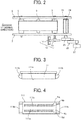
- FIG. 3 is an explanatory side view of a liquid discharge head to be wiped by the wiping device.
- FIG. 4 is an explanatory plan view of the liquid discharge head when viewed from the nozzle face side.
- an object to be wiped by a wiping device 1 includes a liquid discharge head 111 of a liquid discharge apparatus.
- the “liquid discharge head” is also referred to as the "head”.
- the head 111 has a nozzle face 111a provided with a plurality of nozzle arrays Na to Nd each including a plurality of nozzles 111n that discharges liquid.
- the head 111 includes guide members 111b and 111b on both side portions in the nozzle arranged direction. Each guide member 111b is disposed not protruding from the nozzle face 111a, such as being flush with the nozzle face 111a or having a minute step to the nozzle face 111a.
- the nozzle face 111a and the surfaces of the guide members 111b are included in the object to be wiped.
- the wiping device 1 includes a wiping unit 30 retained on a main frame adjusted and supported by the main body of the liquid discharge apparatus, the wiping unit 30 being capable of reciprocating in a wiping direction.
- Side plates 3 and 3 of the wiping unit 30 retain a feeding roller 5 and a winding roller 6, the feeding roller 5 being a core member of a feeding roll 4A including a web 4 as a first wiping member (wiping member) having a belt shape, the web 4 being rolled up, the winding roller 6 being a core member of a winding roll 4B including the web 4 reeled out from the feeding roll 4A, the web 4 being wound up.
- the feeding direction of the web 4 is identical to the direction of an arrow A.
- the side plates 3 retain guide rollers 7 and 8 rotatably.
- a spring 10 presses the press member 9 against the nozzle face 111a or the surface of the guide member 111b, with predetermined pressing force.
- the web 4 includes a sheet material having absorbency, at least having resistance to a liquid to be used, but not fluffing or not causing dust.
- Examples of the web 4 include nonwoven fabric, film, and paper.
- the winding roller 6 receives the driving force of a drive motor 11 through a transmission mechanism 12 including a gear train.
- a code wheel 13 is attached to the guide roller 7, and an encoder sensor 14 including a transmissive photosensor detects a pattern on the code wheel 13.
- the code wheel 13 and the encoder sensor 14 are included in an encoder 15 that detects the distance of movement of the web 4 (the amount of feeding).
- the wiper 24 is retained by a wiper holder 23 retained by the side plates 3 through a shaft 25, the wiper holder 23 being capable of turning.
- the wiper 24 pivots between a first position (home position) indicated with solid lines, a second position indicated with broken lines, and a third position indicated with virtual lines.
- the first position allows the wiper 24 to wipe the nozzle face 111a.
- the second position allows the web 4 to clean the wiper 24 in contact with the web 4.
- the third position is an evacuation position at which the wiper 24 is not in contact with the nozzle face 111a and the web 4.
- the web 4, the feeding roller 5, the winding roller 6, the guide rollers 7 and 8, the press member 9, and the wiper 24 retained by the side plates 3 and 3, are unitized as the wiping unit 30 in a form of a cartridge, so as to be detachably mounted on the main body side.
- the wiping unit 30 is disposed being capable of reciprocating in the direction of arrows Y identical to the nozzle arranged direction of the head 111.
- the reciprocation of the wiping unit 30 can be achieved by, for example, a movement mechanism including a rack 31, a pinion 32, and a moving motor 33 that rotates the pinion 32 or a movement mechanism including a timing belt and pulleys.
- the wiping unit 30 is disposed being capable of moving (lifting and lowering) in the direction indicated by arrow Z in which the web 4 moves forward and backward with respect to the nozzle face 111a, namely, in the up-and-down direction.
- the lifting and lowering of the wiping unit 30 can be achieved by, for example, an elevation mechanism including a cam 35 and an elevation motor 36 that rotates the cam 35 or the elevation mechanism including a rack and a pinion. At this time, the reciprocation mechanism of the wiping unit 30 moves upward and downward, simultaneously with the lifting and lowering.
- a wiping controller 501 that manages the control of the wiping device 1, can be provided, for example, as part of a controller of the liquid discharge apparatus equipped with the wiping device 1.
- the wiping controller 501 controls a motor driver 502 to drive a winding motor 61 that drives the winding roller 6 to rotate.
- the wiping controller 501 counts the number of output pulses of the encoder 15, detects an amount of winding and an amount of rewinding of the web 4, and controls the driving of the winding motor 61.
- the wiping controller 501 controls a motor driver 503 to drive a wiper motor 51 to rotate the wiper holder 23.
- the wiper 24 pivots to the first position, the second position, or the third position.
- the wiper motor 51 includes a stepping motor, and the amount of pivoting of the wiper 24 is controlled with the number of pulses.
- the wiping controller 501 controls a motor driver 505 to drive the moving motor 33 and the elevation motor 36 to control the wiping unit 30 to elevate to the wiping position and to control the wiping unit 30 to relatively move in the wiping direction with respect to the nozzle face 111a.
- the wiping controller 501 inputs respective detected results of a unit home-position sensor 37 that detects the home position of the wiping unit 30 and a wiper home-position sensor 52 that detects the home position of the wiper 24.
- Processing circuitry includes a programmed processor, as a processor includes circuitry.
- a processing circuit also includes devices such as the central processing unit (CPU), an application specific integrated circuit (ASIC), digital signal processor (DSP), field programmable gate array (FPGA), and conventional circuit components arranged to perform the recited functions.
- CPU central processing unit
- ASIC application specific integrated circuit
- DSP digital signal processor
- FPGA field programmable gate array
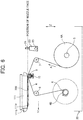
- FIGS. 6 to 11 are explanatory side views for describing the control of the wiping operation.
- liquid (liquid waste) 300 has adhered to the nozzle face 111a of the head 111 due to a maintenance operation.
- the wiping unit 30 lifts to a position of the nozzle face 111a at which the web 4 and the wiper 24 can wipe the nozzle face 111a (wiping start position). Then, the wiping unit 30 moves horizontally in the wiping direction Y1 that is the first direction from a wiping start side of the object to be wiped (nozzle face 111a and the guide member 111b).
- This arrangement allows, as illustrated in FIG. 7 , the web 4 to wipe the nozzle face 111a and the following wiper 24 to wipe the nozzle face 111a, so that a first wiping operation of wiping the entire region of the nozzle face 111a is performed.
- a wiping completion position when the entire region of the nozzle face 111a is wiped in the first wiping operation is, as illustrated in FIG. 8 , a position at which the wiper 24 reaches the end portion in the wiping direction Y1 of the nozzle face 111a.
- the web 4 is spaced apart from the nozzle face 111a, completely.
- the wiper 24 pivots to the second position so as to be in contact with the web 4, and the web 4 cleans the wiper 24.
- a minute amount of liquid waste 300 may adhere to the guide member 111b on the downstream side in the wiping direction of the head 111 that is the portion on the wiping finish side of the object to be wiped.
- the liquid waste 300 adhere to the guide member 111b on the downstream side in the wiping direction of the head 111 includes the liquid waste 300 transferred to the wiper 24 when the wiper 24 pivots to the second position and the liquid waste 300 overflowing in the wiping direction Y1 from the nozzle face 111a when the wiper 24 wipes off the liquid waste 300.
- the wiping unit 30 moves in a second direction Y2 opposite to the wiping direction Y1 that is the first direction such that the web 4 is in contact with the guide member 111b.
- the wiping unit 30 further moves in the second direction Y2, and a second wiping operation of wiping the nozzle face 111a with the web 4, is performed before the nozzle arrays Na to Nd are reached. That is, in the second wiping operation, the web 4 wipes a predetermined region on the wiping finish side of the first wiping operation (here, a region from the guide member 111b before the nozzle arrays).
- This arrangement enables removal of the liquid waste 300 adhering to the surface of the guide member 111b.
- the wiping device 1 includes the first wiping member (wiping member) including the web 4 to wipe an object to be wiped (the nozzle face 111a and the guide member 111b), and circuitry (wiping controller 501) to cause the first wiping member (web 4) to perform a wiping operation to wipe the object to be wiped (the nozzle face 111a and the guide member 111b).
- the circuitry causes the first wiping member (web 4) to perform a first wiping operation to move the first wiping member (web 4) relative to the object to be wiped (the nozzle face 111a and the guide member 111b) in a first direction (Y1) to wipe the object to be wiped (the nozzle face 111a and the guide member 111b) from a wiping start side of the first wiping operation.
- the circuitry (wiping controller 501) further causes the first wiping member (web 4) to perform a second wiping operation to relatively move the first wiping member (web 4) relative to the object to be wiped (the nozzle face 111a and the guide member 111b) in a second direction (Y2) different from the first direction (Y1), to wipe the object to be wiped (the nozzle face 111a and the guide member 111b) from a wiping finish side different from the wiping start side of the first wiping operation with the first wiping member (web 4).
- the bare minimum region (outside the discharge region) is sufficient to wipe.
- a cleaning liquid can be applied to the web 4.
- the cleaning liquid may be dropped onto the press member 9 to apply the cleaning liquid to the web 4, for example.
- the press member 9 serves as an applicator to apply the cleaning liquid to the web 4. This arrangement enables more reliable performance of the absorption and removal of the liquid waste 300.
- the web 4 When the web 4 comes in contact with the guide member 111b in the second operation, the web 4 can stop moving for a predetermined period of time until the wiping unit 30 starts to move in the opposite direction (direction Y2).
- the second wiping operation may hold the first wiping member (web 4) in contact with the object to be wiped (guide member 111b) for a predetermined period of time as illustrated in FIG. 10 .
- a stamping operation of causing the web 4 to contact with the guide member 111b a plurality of times (up-and-down movements) can be performed.
- the amount of wiping movement in the reverse direction of the web 4 can be set arbitrarily.
- the second operation is not necessarily performed every first operation. After the first operation is performed a predetermined number of times, the second operation can be performed. This arrangement can inhibit the duration of a usual wiping operation from lengthening.
- the example in which the second wiping member is provided has been given in the embodiment, but the first wiping member can be provided without the second wiping member.
- the example in which the guide members 111b are provided on both sides in the wiping direction has been given in the embodiment, but no guide members 111b can be provided.
- FIG. 12 is an explanatory plan view of a machine of the liquid discharge apparatus.
- FIG. 13 is an explanatory side view of a main part of the liquid discharge apparatus.
- a liquid discharge apparatus 100 includes a serial head apparatus.
- a guide mechanism including a main guide member 102 bridged across a left side plate 101A and a right side plate 101B, and a sub-guide plate 103, retains a carriage 105 movably in a main scanning direction.
- the carriage 105 is equipped with three liquid discharge units 110 (110a to 110c).
- Each liquid discharge unit 110 includes the head 111 and a sub-tank 112, integrally, the head 111 serving as a liquid discharger, the sub-tank 112 supplying liquid to the head 111.
- a cartridge holder 121 is disposed on the main body side, the cartridge holder 121 holds a plurality of main tanks 120 housing liquids for colors.
- the main tanks 120 are detachably attached to the cartridge holder 121.
- the main tanks 120 serves as liquid cartridges.
- the respective heads 111 of the liquid discharge units 110 are supplied with the liquids for the colors from the main tanks 120 attached to the cartridge holder 121 through a liquid channel 123 including supply tubes for the colors, by a liquid feeding pump.
- a conveyor 140 that sucks the sheet material 130 and then conveys the sheet material 130 opposed to the heads 111.
- the conveyor 140 includes: a conveyance roller 141; a pressing roller 142 pressed in contact with the conveyance roller 141; a platen member 143 opposed to the heads 111; and a suction machine 144 that sucks the sheet material 130 through suction holes 143a of the platen member 143. Note that, although the suction holes 143a are partially illustrated in the figure, the suction holes 143a are disposed over the platen member 143.
- a maintenance mechanism 150 that maintains the heads 111, is disposed on one side in the main scanning direction of the carriage 105.
- the maintenance mechanism 150 that is a head maintenance device according to the present disclosure, includes, for example, caps 151 that cap the nozzle faces 111a of the heads 111 and the wiping unit 30 of the wiping device 1 that wipes the nozzle faces 111a, according to the present disclosure.
- the wiping unit 30 is disposed on a main frame 2.
- the liquid discharge apparatus 100 conveys the sheet material 130 in the conveyance direction with the conveyance roller 141 and the pressing roller 142, the sheet material 130 being sucked on the platen member 143.
- the heads 111 are driven in accordance with a printing signal while the carriage 105 is moving in the main scanning direction. Then, the liquid for a required color is discharged onto the sheet material 130 stopping, and printing is performed by one line. Printing for the next line after the sheet material 130 is conveyed by a predetermined amount, is repeatedly performed. Then, the sheet material 130 is ejected.
- liquid to be discharged is not limited in particular as long as the liquid has a viscosity or surface tension allowing the liquid to be discharged from the head.
- the viscosity is not greater than 30 mPa ⁇ s under ordinary temperature and ordinary pressure or by heating or cooling.
- examples of the liquid include a solution, a suspension, and an emulsion that contain a solvent, such as water or an organic solvent, a colorant, such as dye or pigment, a functional material, such as a polymerizable compound, a resin, or a surfactant, a biocompatible material, such as DNA, amino acid, protein, or calcium, or an edible material, such as a natural colorant.
- Such a solution, a suspension, or an emulsion can be used for inkjet ink, surface treatment solution, a liquid for forming constituent elements of electronic element or light-emitting element or a resist pattern of electronic circuit, or a material solution for three-dimensional fabrication.
- Examples of an energy generation source for discharging the liquid include a piezoelectric actuator (a laminated piezoelectric element or a thin-film piezoelectric element), a thermal actuator that employs an electrothermal conversion element, such as a heating resistor, and an electrostatic actuator including a diaphragm and opposed electrodes.
- a piezoelectric actuator a laminated piezoelectric element or a thin-film piezoelectric element
- a thermal actuator that employs an electrothermal conversion element, such as a heating resistor
- an electrostatic actuator including a diaphragm and opposed electrodes.
- the “liquid discharge unit” includes the liquid discharge head integrated with a functional component or mechanism.
- An example of the “liquid discharge unit” is an assembly of parts relating to liquid discharge.
- the “liquid discharge unit” includes a combination of the liquid discharge head with at least one of a head tank, a carriage, a supply mechanism, a maintenance mechanism, and a main scanning movement mechanism.
- examples of the integration include mutually securing of the liquid discharge head and the functional component or mechanism through fastening, bonding, or engaging, and movably retention of one to the other.
- the liquid discharge head and the functional component or mechanism may be provided mutually detachably.
- the liquid discharge unit provided is the integration of the liquid discharge head with the head tank.
- the liquid discharge head and the head tank are coupled mutually through a tube.
- a unit including a filter can be added between the head tank and the liquid discharge head of the liquid discharge unit.
- liquid discharge unit As the liquid discharge unit, provided is the integration of the liquid discharge head with the carriage.
- the liquid discharge unit As the liquid discharge unit, provided is the integration of the liquid discharge head with the main scanning movement mechanism, in which the liquid discharge head is retained movably by a guide member included in part of the main scanning movement mechanism. Provided is the integration of the liquid discharge head, the carriage, and the main scanning movement mechanism.
- the liquid discharge unit As the liquid discharge unit, provided is the integration of the liquid discharge head, the carriage, and the maintenance mechanism, in which a cap member included in part of the maintenance mechanism is secured to the carriage having the liquid discharge head attached.
- the liquid discharge unit As the liquid discharge unit, provided is the integration of the liquid discharge head and the supply mechanism, in which a tube is coupled to the liquid discharge head having the head tank or a channel component attached. Through the tube, the liquid in a liquid storage source is supplied to the liquid discharge head.
- the main scanning movement mechanism includes the guide member as a single body.
- the supply mechanism includes the tube as a single body and a loader as a single body.
- liquid discharge apparatus is an apparatus including the liquid discharge head or the liquid discharge unit, the apparatus being to drive the liquid discharge head to discharge the liquid.
- liquid discharge apparatus include an apparatus capable of discharging liquid to an object to which the liquid can adhere, and an apparatus that discharges liquid into gas or liquid.
- the "liquid discharge apparatus” can include not only units involved in feeding, conveyance, and paper ejection of the object to which liquid can adhere, but also a preprocessing device and a postprocessing device.
- liquid discharge apparatus examples include: an image forming apparatus that discharges ink to form an image on a paper sheet; and a solid fabrication apparatus (three-dimensional fabrication apparatus) that discharges a fabrication liquid to a powder layer including powder formed in layers in order to shape a solid shaped object (three-dimensional fabrication object).
- the "liquid discharge apparatus” is not limited to visualization of a meaningful image including a character or a figure, with the discharged liquid. For example, formation of a pattern having no meaning and shaping of the pattern to a three-dimensional image, are included.
- the "object to which liquid can adhere” described above means an object to which liquid can adhere at least temporarily, the liquid being to adhere to and to fix on the object or to adhere to and to permeate the object.
- Specific examples include recording media, such as a paper sheet, recording paper, a recording paper sheet, film, and cloth, electronic components, such as an electronic substrate and a piezoelectric element, and media, such as a powder layer (granular layer), an organ model, and a testing cell. Unless otherwise limited in particular, any object to which liquid adheres, is included.
- the material of the "object to which liquid can adhere” may be any material, such as paper, thread, fiber, fabric cloth, leather, metal, plastic, glass, wood, or ceramics as long as liquid can adhere to at least temporarily.
- the "liquid discharge apparatus” may be, but is not limited to, an apparatus that relatively moves the liquid discharge head and the object to which liquid can adhere. Specific examples include a serial head apparatus that moves the liquid discharge head and a line head apparatus that does not move the liquid discharge head.
- liquid discharge apparatus examples include a treatment liquid coating apparatus that discharges a treatment liquid onto a paper sheet in order to coat the treatment liquid on the surface of the paper sheet for reforming of the surface of the paper sheet, and an injection granulation apparatus that sprays a composition liquid including raw material dispersed in a solution, through a nozzle, to granulate fine particles of the raw material.
Landscapes
- Ink Jet (AREA)
Abstract
Description
- The present disclosure relates to a wiping device, a head maintenance device, and a liquid discharge apparatus.
- In a case where a liquid discharge head that discharges liquid is used, in order to maintain the state of a nozzle, provided is a maintenance mechanism (maintenance device) including a cap that caps a nozzle face and a wiping device that wipes and cleans the nozzle face.
- A device including a blade-shaped wiper member that wipes a nozzle face, is known, in which a liquid discharge head moves relatively in a first direction with respect to the wiper member such that the nozzle face is wiped, then the liquid discharge head moves in a second direction such that the side face of the rear end in the wiping direction of the liquid discharge head is in contact with the wiper member, and then the liquid discharge head moves again in the first direction to be spaced apart from the wiper member (see, for example,
JP-2003-025596-A - However, when the nozzle face is wiped with a belt-shaped wiping member such as a web as a wiping member, a waste liquid may be accumulated on a wiping end side of a part of the liquid discharge head.
- An object of the present disclosure is to reliably remove an adhered object adhered to an object to be wiped from the object to be wiped.
- In an aspect of this disclosure, a novel wiping device is provided in which the wiping device includes a wiping member including a web to wipe an object to be wiped, and circuitry to cause the wiping member to perform a wiping operation to wipe the object to be wiped. The circuitry causes the wiping member to perform a first wiping operation to move the wiping member relative to the object to be wiped in a first direction to wipe the object to be wiped from a wiping start side of the first wiping operation, and perform a second wiping operation to relatively move the wiping member relative to the object to be wiped in a second direction different from the first direction, to wipe the object to be wiped from a wiping finish side different from the wiping start side of the first wiping operation with the wiping member.
- According to the present disclosure, the wiping device can reliably remove an adhered object adhered to an object to be wiped from the object to be wiped.
-
-
FIG. 1 is an explanatory side view of a wiping device according to a first embodiment of the present disclosure; -
FIG. 2 is an explanatory plan view of the wiping device; -
FIG. 3 is an explanatory side view of a liquid discharge head to be wiped by the wiping device; -
FIG. 4 is an explanatory plan view of the liquid discharge head when viewed from the nozzle face side; -
FIG. 5 is an explanatory block diagram of parts according to the control of a wiping operation in the wiping device; -
FIG. 6 is an explanatory side view for describing the control of a first wiping operation of a wiping controller; -
FIG. 7 is an explanatory side view for describing the control of the first wiping operation of the wiping controller, followingFIG. 6 ; -
FIG. 8 is an explanatory side view for describing the control of the first wiping operation of the wiping controller, followingFIG. 7 ; -
FIG. 9 is an explanatory side view for describing the control of a wiper cleaning operation of the wiping controller; -
FIG. 10 is an explanatory side view for describing the control of a second wiping operation of the wiping controller; -
FIG. 11 is an explanatory side view for describing the control of the second wiping operation of the wiping controller, followingFIG. 10 ; -
FIG. 12 is an explanatory plan view of a machine of an exemplary liquid discharge apparatus according to the present disclosure; and -
FIG. 13 is an explanatory side view of a main part of the liquid discharge apparatus according to the present disclosure. - In describing embodiments illustrated in the drawings, specific terminology is employed for the sake of clarity. However, the disclosure of this patent specification is not intended to be limited to the specific terminology so selected and it is to be understood that each specific element includes all technical equivalents that operate in a similar manner and achieve similar results.
- Although the embodiments are described with technical limitations with reference to the attached drawings, such description is not intended to limit the scope of the disclosure and all of the components or elements described in the embodiments of this disclosure are not necessarily indispensable.
- Referring now to the drawings, embodiments of the present disclosure are described below. In the drawings for explaining the following embodiments, the same reference codes are allocated to elements (members or components) having the same function or shape and redundant descriptions thereof are omitted below.
- An embodiment of the present disclosure will be described below referring to the accompanying drawings. A first embodiment of the present disclosure will be described referring to
FIGS. 1 to 3 .FIG. 1 is an explanatory side view of a wiping device according to the embodiment.FIG. 2 is an explanatory plan view of the wiping device.FIG. 3 is an explanatory side view of a liquid discharge head to be wiped by the wiping device.FIG. 4 is an explanatory plan view of the liquid discharge head when viewed from the nozzle face side. - In the present embodiment, an object to be wiped by a
wiping device 1 includes aliquid discharge head 111 of a liquid discharge apparatus. Hereinafter, the "liquid discharge head" is also referred to as the "head". - As illustrated in
FIGS. 3 and 4 , thehead 111 has anozzle face 111a provided with a plurality of nozzle arrays Na to Nd each including a plurality ofnozzles 111n that discharges liquid. Thehead 111 includesguide members guide member 111b is disposed not protruding from thenozzle face 111a, such as being flush with thenozzle face 111a or having a minute step to thenozzle face 111a. Thenozzle face 111a and the surfaces of theguide members 111b are included in the object to be wiped. - The
wiping device 1 includes awiping unit 30 retained on a main frame adjusted and supported by the main body of the liquid discharge apparatus, thewiping unit 30 being capable of reciprocating in a wiping direction. -
Side plates wiping unit 30 retain afeeding roller 5 and awinding roller 6, thefeeding roller 5 being a core member of afeeding roll 4A including aweb 4 as a first wiping member (wiping member) having a belt shape, theweb 4 being rolled up, thewinding roller 6 being a core member of awinding roll 4B including theweb 4 reeled out from thefeeding roll 4A, theweb 4 being wound up. Note that the feeding direction of theweb 4 is identical to the direction of an arrow A. - The
side plates 3 retainguide rollers press member 9 that presses theweb 4 against thenozzle face 111a or the surface of theguide member 111b included in the object to be wiped, is disposed between theguide rollers spring 10 presses thepress member 9 against thenozzle face 111a or the surface of theguide member 111b, with predetermined pressing force. - Preferably, the
web 4 includes a sheet material having absorbency, at least having resistance to a liquid to be used, but not fluffing or not causing dust. Examples of theweb 4 include nonwoven fabric, film, and paper. - The winding
roller 6 receives the driving force of adrive motor 11 through atransmission mechanism 12 including a gear train. - A
code wheel 13 is attached to theguide roller 7, and anencoder sensor 14 including a transmissive photosensor detects a pattern on thecode wheel 13. Thecode wheel 13 and theencoder sensor 14 are included in anencoder 15 that detects the distance of movement of the web 4 (the amount of feeding). - A
wiper 24 including a blade-shaped second wiping member (another wiping member), is disposed on the upstream side in a first wiping direction (direction of an arrow Y1) with respect to theweb 4. Thewiper 24 is retained by awiper holder 23 retained by theside plates 3 through ashaft 25, thewiper holder 23 being capable of turning. - When the wiper holder 23 pivots (rotates), the
wiper 24 pivots between a first position (home position) indicated with solid lines, a second position indicated with broken lines, and a third position indicated with virtual lines. - Here, the first position allows the
wiper 24 to wipe thenozzle face 111a. The second position allows theweb 4 to clean thewiper 24 in contact with theweb 4. The third position is an evacuation position at which thewiper 24 is not in contact with thenozzle face 111a and theweb 4. - The
web 4, thefeeding roller 5, thewinding roller 6, theguide rollers press member 9, and thewiper 24 retained by theside plates wiping unit 30 in a form of a cartridge, so as to be detachably mounted on the main body side. - The
wiping unit 30 is disposed being capable of reciprocating in the direction of arrows Y identical to the nozzle arranged direction of thehead 111. The reciprocation of thewiping unit 30 can be achieved by, for example, a movement mechanism including arack 31, apinion 32, and a movingmotor 33 that rotates thepinion 32 or a movement mechanism including a timing belt and pulleys. - The
wiping unit 30 is disposed being capable of moving (lifting and lowering) in the direction indicated by arrow Z in which theweb 4 moves forward and backward with respect to thenozzle face 111a, namely, in the up-and-down direction. The lifting and lowering of thewiping unit 30 can be achieved by, for example, an elevation mechanism including acam 35 and anelevation motor 36 that rotates thecam 35 or the elevation mechanism including a rack and a pinion. At this time, the reciprocation mechanism of the wipingunit 30 moves upward and downward, simultaneously with the lifting and lowering. - Next, parts according to the control of a wiping operation in the
wiping device 1, will be described referring to the explanatory block diagram ofFIG. 5 . - A wiping
controller 501 that manages the control of thewiping device 1, can be provided, for example, as part of a controller of the liquid discharge apparatus equipped with thewiping device 1. - The wiping
controller 501 controls amotor driver 502 to drive a windingmotor 61 that drives the windingroller 6 to rotate. In this case, the wipingcontroller 501 counts the number of output pulses of theencoder 15, detects an amount of winding and an amount of rewinding of theweb 4, and controls the driving of the windingmotor 61. - The wiping
controller 501 controls amotor driver 503 to drive awiper motor 51 to rotate thewiper holder 23. Thus, thewiper 24 pivots to the first position, the second position, or the third position. Thewiper motor 51 includes a stepping motor, and the amount of pivoting of thewiper 24 is controlled with the number of pulses. - The wiping
controller 501 controls amotor driver 505 to drive the movingmotor 33 and theelevation motor 36 to control the wipingunit 30 to elevate to the wiping position and to control the wipingunit 30 to relatively move in the wiping direction with respect to thenozzle face 111a. - The wiping
controller 501 inputs respective detected results of a unit home-position sensor 37 that detects the home position of the wipingunit 30 and a wiper home-position sensor 52 that detects the home position of thewiper 24. - Functions executed by the wiping
controller 501 may be implemented by one or more processing circuits or circuitry. Processing circuitry includes a programmed processor, as a processor includes circuitry. A processing circuit also includes devices such as the central processing unit (CPU), an application specific integrated circuit (ASIC), digital signal processor (DSP), field programmable gate array (FPGA), and conventional circuit components arranged to perform the recited functions. - Next, the control of a wiping operation of the wiping controller, will be described referring to
FIGS. 6 to 11. FIGS. 6 to 11 are explanatory side views for describing the control of the wiping operation. - It is assumed that liquid (liquid waste) 300 has adhered to the
nozzle face 111a of thehead 111 due to a maintenance operation. - As illustrated in
FIG. 6 , the wipingunit 30 lifts to a position of thenozzle face 111a at which theweb 4 and thewiper 24 can wipe thenozzle face 111a (wiping start position). Then, the wipingunit 30 moves horizontally in the wiping direction Y1 that is the first direction from a wiping start side of the object to be wiped (nozzle face 111a and theguide member 111b). - This arrangement allows, as illustrated in
FIG. 7 , theweb 4 to wipe thenozzle face 111a and the followingwiper 24 to wipe thenozzle face 111a, so that a first wiping operation of wiping the entire region of thenozzle face 111a is performed. - A wiping completion position when the entire region of the
nozzle face 111a is wiped in the first wiping operation, is, as illustrated inFIG. 8 , a position at which thewiper 24 reaches the end portion in the wiping direction Y1 of thenozzle face 111a. At the wiping completion position, theweb 4 is spaced apart from thenozzle face 111a, completely. - At this time, because the
liquid waste 300 removed from thenozzle face 111a has adhered to thewiper 24, as illustrated inFIG. 9 , thewiper 24 pivots to the second position so as to be in contact with theweb 4, and theweb 4 cleans thewiper 24. - A minute amount of
liquid waste 300 may adhere to theguide member 111b on the downstream side in the wiping direction of thehead 111 that is the portion on the wiping finish side of the object to be wiped. Theliquid waste 300 adhere to theguide member 111b on the downstream side in the wiping direction of thehead 111 includes theliquid waste 300 transferred to thewiper 24 when thewiper 24 pivots to the second position and theliquid waste 300 overflowing in the wiping direction Y1 from thenozzle face 111a when thewiper 24 wipes off theliquid waste 300. - In order to remove the
liquid waste 300 adhering to theguide member 111b on the downstream side in the wiping direction of thehead 111, as illustrated inFIG. 10 , the wipingunit 30 moves in a second direction Y2 opposite to the wiping direction Y1 that is the first direction such that theweb 4 is in contact with theguide member 111b. - Then, as illustrated in
FIG. 11 , the wipingunit 30 further moves in the second direction Y2, and a second wiping operation of wiping thenozzle face 111a with theweb 4, is performed before the nozzle arrays Na to Nd are reached. That is, in the second wiping operation, theweb 4 wipes a predetermined region on the wiping finish side of the first wiping operation (here, a region from theguide member 111b before the nozzle arrays). - This arrangement enables removal of the
liquid waste 300 adhering to the surface of theguide member 111b. - Thus, the
wiping device 1 includes the first wiping member (wiping member) including theweb 4 to wipe an object to be wiped (thenozzle face 111a and theguide member 111b), and circuitry (wiping controller 501) to cause the first wiping member (web 4) to perform a wiping operation to wipe the object to be wiped (thenozzle face 111a and theguide member 111b). - The circuitry (wiping controller 501) causes the first wiping member (web 4) to perform a first wiping operation to move the first wiping member (web 4) relative to the object to be wiped (the
nozzle face 111a and theguide member 111b) in a first direction (Y1) to wipe the object to be wiped (thenozzle face 111a and theguide member 111b) from a wiping start side of the first wiping operation. - The circuitry (wiping controller 501) further causes the first wiping member (web 4) to perform a second wiping operation to relatively move the first wiping member (web 4) relative to the object to be wiped (the
nozzle face 111a and theguide member 111b) in a second direction (Y2) different from the first direction (Y1), to wipe the object to be wiped (thenozzle face 111a and theguide member 111b) from a wiping finish side different from the wiping start side of the first wiping operation with the first wiping member (web 4). - For the removal of liquid waste with the
web 4, because theweb 4 absorbs liquid easily, the liquid waste can be removed with theweb 4 in contact with thenozzle face 111a. Therefore, the bare minimum region (outside the discharge region) is sufficient to wipe. - Note that, at this time, locating the
wiper 24 at the second position or the third position, allows thewiper 24 to be not in contact with thenozzle face 111a, so that thewiper 24 has no influence on the wiping. Rendering the amount of movement in the opposite direction (direction Y2) to the bare minimum, enables wiping time to shorten. - In the embodiment, before the
web 4 starts to wipe thenozzle face 111a in the first operation, a cleaning liquid can be applied to theweb 4. The cleaning liquid may be dropped onto thepress member 9 to apply the cleaning liquid to theweb 4, for example. Thus, thepress member 9 serves as an applicator to apply the cleaning liquid to theweb 4. This arrangement enables more reliable performance of the absorption and removal of theliquid waste 300. - When the
web 4 comes in contact with theguide member 111b in the second operation, theweb 4 can stop moving for a predetermined period of time until the wipingunit 30 starts to move in the opposite direction (direction Y2). Thus, the second wiping operation may hold the first wiping member (web 4) in contact with the object to be wiped (guidemember 111b) for a predetermined period of time as illustrated inFIG. 10 . Furthermore, a stamping operation of causing theweb 4 to contact with theguide member 111b a plurality of times (up-and-down movements) can be performed. - In the second operation, the amount of wiping movement in the reverse direction of the
web 4 can be set arbitrarily. - Because the amount of liquid waste that adheres to the
guide member 111b is minute, the second operation is not necessarily performed every first operation. After the first operation is performed a predetermined number of times, the second operation can be performed. This arrangement can inhibit the duration of a usual wiping operation from lengthening. - Note that, the example in which the second wiping member is provided has been given in the embodiment, but the first wiping member can be provided without the second wiping member. The example in which the
guide members 111b are provided on both sides in the wiping direction has been given in the embodiment, but noguide members 111b can be provided. - Next, an exemplary liquid discharge apparatus according to the present disclosure, will be described referring to
FIGS. 12 and13 .FIG. 12 is an explanatory plan view of a machine of the liquid discharge apparatus.FIG. 13 is an explanatory side view of a main part of the liquid discharge apparatus. - A
liquid discharge apparatus 100 includes a serial head apparatus. A guide mechanism including amain guide member 102 bridged across aleft side plate 101A and aright side plate 101B, and asub-guide plate 103, retains acarriage 105 movably in a main scanning direction. - The
carriage 105 is equipped with three liquid discharge units 110 (110a to 110c). Eachliquid discharge unit 110 includes thehead 111 and a sub-tank 112, integrally, thehead 111 serving as a liquid discharger, the sub-tank 112 supplying liquid to thehead 111. - A
cartridge holder 121 is disposed on the main body side, thecartridge holder 121 holds a plurality ofmain tanks 120 housing liquids for colors. Themain tanks 120 are detachably attached to thecartridge holder 121. Themain tanks 120 serves as liquid cartridges. Therespective heads 111 of theliquid discharge units 110 are supplied with the liquids for the colors from themain tanks 120 attached to thecartridge holder 121 through aliquid channel 123 including supply tubes for the colors, by a liquid feeding pump. - Meanwhile, in order to convey a
sheet material 130 in a conveyance direction, provided is aconveyor 140 that sucks thesheet material 130 and then conveys thesheet material 130 opposed to theheads 111. - The
conveyor 140 includes: aconveyance roller 141; apressing roller 142 pressed in contact with theconveyance roller 141; aplaten member 143 opposed to theheads 111; and asuction machine 144 that sucks thesheet material 130 throughsuction holes 143a of theplaten member 143. Note that, although thesuction holes 143a are partially illustrated in the figure, thesuction holes 143a are disposed over theplaten member 143. - A
maintenance mechanism 150 that maintains theheads 111, is disposed on one side in the main scanning direction of thecarriage 105. - The
maintenance mechanism 150 that is a head maintenance device according to the present disclosure, includes, for example, caps 151 that cap the nozzle faces 111a of theheads 111 and the wipingunit 30 of thewiping device 1 that wipes the nozzle faces 111a, according to the present disclosure. The wipingunit 30 is disposed on amain frame 2. - The
liquid discharge apparatus 100 conveys thesheet material 130 in the conveyance direction with theconveyance roller 141 and thepressing roller 142, thesheet material 130 being sucked on theplaten member 143. - Thus, the
heads 111 are driven in accordance with a printing signal while thecarriage 105 is moving in the main scanning direction. Then, the liquid for a required color is discharged onto thesheet material 130 stopping, and printing is performed by one line. Printing for the next line after thesheet material 130 is conveyed by a predetermined amount, is repeatedly performed. Then, thesheet material 130 is ejected. - In the present application, liquid to be discharged is not limited in particular as long as the liquid has a viscosity or surface tension allowing the liquid to be discharged from the head. Preferably, the viscosity is not greater than 30 mPa·s under ordinary temperature and ordinary pressure or by heating or cooling. More specifically, examples of the liquid include a solution, a suspension, and an emulsion that contain a solvent, such as water or an organic solvent, a colorant, such as dye or pigment, a functional material, such as a polymerizable compound, a resin, or a surfactant, a biocompatible material, such as DNA, amino acid, protein, or calcium, or an edible material, such as a natural colorant. Such a solution, a suspension, or an emulsion can be used for inkjet ink, surface treatment solution, a liquid for forming constituent elements of electronic element or light-emitting element or a resist pattern of electronic circuit, or a material solution for three-dimensional fabrication.
- Examples of an energy generation source for discharging the liquid include a piezoelectric actuator (a laminated piezoelectric element or a thin-film piezoelectric element), a thermal actuator that employs an electrothermal conversion element, such as a heating resistor, and an electrostatic actuator including a diaphragm and opposed electrodes.
- The "liquid discharge unit" includes the liquid discharge head integrated with a functional component or mechanism. An example of the "liquid discharge unit" is an assembly of parts relating to liquid discharge. For example, the "liquid discharge unit" includes a combination of the liquid discharge head with at least one of a head tank, a carriage, a supply mechanism, a maintenance mechanism, and a main scanning movement mechanism.
- Here, examples of the integration include mutually securing of the liquid discharge head and the functional component or mechanism through fastening, bonding, or engaging, and movably retention of one to the other. The liquid discharge head and the functional component or mechanism may be provided mutually detachably.
- For example, as the liquid discharge unit, provided is the integration of the liquid discharge head with the head tank. For the integration, the liquid discharge head and the head tank are coupled mutually through a tube. Here, a unit including a filter can be added between the head tank and the liquid discharge head of the liquid discharge unit.
- As the liquid discharge unit, provided is the integration of the liquid discharge head with the carriage.
- As the liquid discharge unit, provided is the integration of the liquid discharge head with the main scanning movement mechanism, in which the liquid discharge head is retained movably by a guide member included in part of the main scanning movement mechanism. Provided is the integration of the liquid discharge head, the carriage, and the main scanning movement mechanism.
- As the liquid discharge unit, provided is the integration of the liquid discharge head, the carriage, and the maintenance mechanism, in which a cap member included in part of the maintenance mechanism is secured to the carriage having the liquid discharge head attached.
- As the liquid discharge unit, provided is the integration of the liquid discharge head and the supply mechanism, in which a tube is coupled to the liquid discharge head having the head tank or a channel component attached. Through the tube, the liquid in a liquid storage source is supplied to the liquid discharge head.
- The main scanning movement mechanism includes the guide member as a single body. The supply mechanism includes the tube as a single body and a loader as a single body.
- An example of the "liquid discharge apparatus" is an apparatus including the liquid discharge head or the liquid discharge unit, the apparatus being to drive the liquid discharge head to discharge the liquid. Examples of the liquid discharge apparatus include an apparatus capable of discharging liquid to an object to which the liquid can adhere, and an apparatus that discharges liquid into gas or liquid.
- The "liquid discharge apparatus" can include not only units involved in feeding, conveyance, and paper ejection of the object to which liquid can adhere, but also a preprocessing device and a postprocessing device.
- Examples of the "liquid discharge apparatus" include: an image forming apparatus that discharges ink to form an image on a paper sheet; and a solid fabrication apparatus (three-dimensional fabrication apparatus) that discharges a fabrication liquid to a powder layer including powder formed in layers in order to shape a solid shaped object (three-dimensional fabrication object).
- The "liquid discharge apparatus" is not limited to visualization of a meaningful image including a character or a figure, with the discharged liquid. For example, formation of a pattern having no meaning and shaping of the pattern to a three-dimensional image, are included.
- The "object to which liquid can adhere" described above means an object to which liquid can adhere at least temporarily, the liquid being to adhere to and to fix on the object or to adhere to and to permeate the object. Specific examples include recording media, such as a paper sheet, recording paper, a recording paper sheet, film, and cloth, electronic components, such as an electronic substrate and a piezoelectric element, and media, such as a powder layer (granular layer), an organ model, and a testing cell. Unless otherwise limited in particular, any object to which liquid adheres, is included.
- The material of the "object to which liquid can adhere" may be any material, such as paper, thread, fiber, fabric cloth, leather, metal, plastic, glass, wood, or ceramics as long as liquid can adhere to at least temporarily.
- The "liquid discharge apparatus" may be, but is not limited to, an apparatus that relatively moves the liquid discharge head and the object to which liquid can adhere. Specific examples include a serial head apparatus that moves the liquid discharge head and a line head apparatus that does not move the liquid discharge head.
- Further examples of the "liquid discharge apparatus" include a treatment liquid coating apparatus that discharges a treatment liquid onto a paper sheet in order to coat the treatment liquid on the surface of the paper sheet for reforming of the surface of the paper sheet, and an injection granulation apparatus that sprays a composition liquid including raw material dispersed in a solution, through a nozzle, to granulate fine particles of the raw material.
- Note that the terms "image formation", "recording", "character printing", "image printing", "printing", and "shaping" are used as a synonym in the present application.
Claims (10)
- A wiping device (1) comprising:a wiping member (4) including a web to wipe an object to be wiped; andcircuitry (501) to cause the wiping member to perform a wiping operation to wipe the object to be wiped,wherein the circuitry causes the wiping member to:perform a first wiping operation to move the wiping member (4) relative to the object to be wiped in a first direction to wipe the object to be wiped from a wiping start side of the first wiping operation; andperform a second wiping operation to relatively move the wiping member (4) relative to the object to be wiped in a second direction different from the first direction, to wipe the object to be wiped from a wiping finish side different from the wiping start side of the first wiping operation with the wiping member (4).
- The wiping device (1) according to claim 1, further comprising:another wiping member (24) including a blade to wipe the object to be wiped,wherein said another wiping member (24) is movable between a wiping position at which said another wiping member (24) is in contact with the object to be wiped to wipe the object to be wiped and an evacuation position at which said another wiping member (24) is not in contact with the object to be wiped,the circuitry causes said another wiping member (24) to:move to the wiping position in the first wiping operation, andmove to the evacuation position in the second wiping operation.
- The wiping device (1) according to claim 1 or 2, further comprising an applicator to apply a cleaning liquid to the wiping member (4).
- The wiping device (1) according to any of claims 1 to 3,
wherein the circuitry causes the wiping member to perform the second wiping operation after performing the first wiping operation a predetermined number of times. - The wiping device (1) according to any of claims 1 to 4,
wherein the second wiping operation holds the wiping member (4) in contact with the object to be wiped for a predetermined period of time. - The wiping device (1) according to any of claims 1 to 5,
wherein the circuitry causes the wiping member to wipe a nozzle face (111a) of a liquid discharge head (111) to discharge a liquid from nozzles formed in the nozzle face. - The wiping device (1) according to claim 6,
wherein the liquid discharge head includes a guide member (111b) disposed at an end portion of the liquid discharge head (111) in at least one of the first direction and the second direction, and
the circuitry causes the wiping member to wipe the guide member (111b) in the second wiping operation. - The wiping device (1) according to any of claims 1 to 7, wherein the second direction is opposite to the first direction.
- A head maintenance device comprising the wiping device (1) according to claim 1 to maintain a liquid discharge head (111) to discharge a liquid from nozzles formed in a nozzle face (111a) as the object to be wiped.
- A liquid discharge apparatus comprising:a liquid discharge head (111) to discharge a liquid to discharge a liquid from nozzles formed in a nozzle face (111a); andthe wiping device (1) according to any one of claims 1 through 8 to wipe the nozzle face of the liquid discharge head as the object to be wiped.
Applications Claiming Priority (1)
| Application Number | Priority Date | Filing Date | Title |
|---|---|---|---|
| JP2018029699A JP7069813B2 (en) | 2018-02-22 | 2018-02-22 | Wiping device, head maintenance device, liquid discharge device |
Publications (2)
| Publication Number | Publication Date |
|---|---|
| EP3530466A1 true EP3530466A1 (en) | 2019-08-28 |
| EP3530466B1 EP3530466B1 (en) | 2023-04-05 |
Family
ID=65411814
Family Applications (1)
| Application Number | Title | Priority Date | Filing Date |
|---|---|---|---|
| EP19156659.5A Active EP3530466B1 (en) | 2018-02-22 | 2019-02-12 | Wiping device, head maintenance device, and liquid discharge apparatus |
Country Status (3)
| Country | Link |
|---|---|
| US (1) | US10611157B2 (en) |
| EP (1) | EP3530466B1 (en) |
| JP (1) | JP7069813B2 (en) |
Cited By (1)
| Publication number | Priority date | Publication date | Assignee | Title |
|---|---|---|---|---|
| EP4607157A4 (en) * | 2022-10-21 | 2025-12-17 | Contemporary Amperex Technology Hong Kong Ltd | LIQUID INJECTION DEVICE |
Families Citing this family (12)
| Publication number | Priority date | Publication date | Assignee | Title |
|---|---|---|---|---|
| WO2021020458A1 (en) | 2019-08-01 | 2021-02-04 | 天野エンザイム株式会社 | Novel lipase and use thereof |
| JP7427904B2 (en) * | 2019-10-09 | 2024-02-06 | セイコーエプソン株式会社 | Liquid collection device, liquid injection device, control method for liquid injection device |
| JP7443725B2 (en) * | 2019-11-13 | 2024-03-06 | セイコーエプソン株式会社 | Liquid injection equipment, maintenance method for liquid injection equipment |
| JP7468134B2 (en) * | 2020-05-18 | 2024-04-16 | ブラザー工業株式会社 | Cleaning liquid, cleaning method, and recording apparatus. |
| US11433675B2 (en) | 2020-06-17 | 2022-09-06 | Ricoh Company, Ltd. | Maintenance device and liquid discharge apparatus |
| JP7615576B2 (en) | 2020-09-08 | 2025-01-17 | セイコーエプソン株式会社 | LIQUID EJECTING APPARATUS AND METHOD FOR CONTROLLING LIQUID EJECTING APPARATUS |
| CN112319054B (en) * | 2020-09-18 | 2022-05-10 | 季华实验室 | A nozzle wiping device and inkjet printing equipment |
| JP7689656B2 (en) | 2021-03-25 | 2025-06-09 | 株式会社リコー | Liquid ejection device, liquid storage container, cleaning liquid container |
| JP7694089B2 (en) | 2021-03-25 | 2025-06-18 | 株式会社リコー | Liquid ejection device, liquid storage container, refill container, cleaning liquid container |
| JP2024057659A (en) | 2022-10-13 | 2024-04-25 | 株式会社リコー | Head maintenance device, liquid ejection device |
| JP2024136821A (en) * | 2023-03-24 | 2024-10-04 | 株式会社リコー | Wiping device, liquid ejection device |
| JP2024138705A (en) * | 2023-03-27 | 2024-10-09 | 株式会社リコー | Wiping device, liquid ejection device |
Citations (5)
| Publication number | Priority date | Publication date | Assignee | Title |
|---|---|---|---|---|
| JP2003025596A (en) | 2001-07-11 | 2003-01-29 | Brother Ind Ltd | Inkjet recording device |
| US20130249998A1 (en) * | 2012-03-22 | 2013-09-26 | Seiko Epson Corporation | Maintenance device and liquid ejecting apparatus |
| US20160243836A1 (en) * | 2015-02-19 | 2016-08-25 | Kyocera Document Solutions Inc. | Recovery system for recording head, ink-jet recording apparatus including the same, and recovery method for the recording head |
| US20170157935A1 (en) * | 2014-07-03 | 2017-06-08 | Mimaki Engineering Co., Ltd. | Head washing device and inkjet printer |
| US20170225471A1 (en) * | 2016-02-10 | 2017-08-10 | Fujifilm Corporation | Liquid ejection device and cleaning method |
Family Cites Families (21)
| Publication number | Priority date | Publication date | Assignee | Title |
|---|---|---|---|---|
| JP4784195B2 (en) * | 2004-12-28 | 2011-10-05 | コニカミノルタエムジー株式会社 | Head maintenance mechanism and inkjet printer |
| KR100727971B1 (en) | 2005-09-01 | 2007-06-14 | 삼성전자주식회사 | Wiper, cleaning device, and inkjet image forming apparatus having same |
| JP2007230033A (en) | 2006-02-28 | 2007-09-13 | Fuji Xerox Co Ltd | Droplet ejection apparatus |
| JP4940917B2 (en) | 2006-12-01 | 2012-05-30 | 富士ゼロックス株式会社 | Droplet discharge device |
| JP2010179631A (en) | 2009-02-09 | 2010-08-19 | Fujifilm Corp | Inkjet head, method of manufacturing the same, and inkjet recording apparatus |
| JP5223934B2 (en) | 2010-03-29 | 2013-06-26 | パナソニック株式会社 | Inkjet device |
| JP5612962B2 (en) * | 2010-08-12 | 2014-10-22 | 富士フイルム株式会社 | Nozzle surface cleaning device and droplet discharge device |
| JP2014000704A (en) | 2012-06-18 | 2014-01-09 | Ricoh Co Ltd | Cleaning device for droplet discharge head, cleaning method, and droplet discharge device |
| EP2919996A1 (en) * | 2012-11-19 | 2015-09-23 | OCE-Technologies B.V. | Assembly of a print head and a maintenance unit and method for the use of said assembly |
| EP2738004B1 (en) * | 2012-11-30 | 2018-10-31 | Seiko Epson Corporation | Ink jet recording apparatus |
| JP6248556B2 (en) | 2013-11-07 | 2017-12-20 | セイコーエプソン株式会社 | Liquid ejecting head cleaning device and liquid ejecting device provided with the cleaning device |
| JP2016155279A (en) | 2015-02-24 | 2016-09-01 | 理想科学工業株式会社 | Maintenance mechanism of ink jet printing device |
| JP6606958B2 (en) * | 2015-10-05 | 2019-11-20 | セイコーエプソン株式会社 | Liquid ejecting apparatus and cleaning apparatus |
| US9879144B2 (en) * | 2016-03-16 | 2018-01-30 | Ricoh Company, Ltd. | Cleaning solution, set of ink and cleaning solution, cleaning method, cleaning apparatus, printing method, and printing apparatus |
| JP6625484B2 (en) * | 2016-05-19 | 2019-12-25 | 富士フイルム株式会社 | Nozzle surface wiping device, liquid ejection device, and head cleaning method |
| US10226929B2 (en) | 2016-11-10 | 2019-03-12 | Ricoh Company, Ltd. | Head cleaner, maintenance device, and liquid discharge apparatus |
| US10350895B2 (en) | 2017-03-15 | 2019-07-16 | Ricoh Company, Ltd. | Head cleaner and liquid discharge apparatus |
| WO2018231205A1 (en) * | 2017-06-13 | 2018-12-20 | Hewlett-Packard Development Company, L.P. | Wiper blade positions |
| JP6988245B2 (en) * | 2017-08-07 | 2022-01-05 | セイコーエプソン株式会社 | Liquid sprayer |
| JP6939292B2 (en) * | 2017-09-08 | 2021-09-22 | 株式会社リコー | Droplet ejection device and image forming device |
| EP3498476A1 (en) * | 2017-12-18 | 2019-06-19 | Ricoh Company, Limited | Liquid discharge apparatus |
-
2018
- 2018-02-22 JP JP2018029699A patent/JP7069813B2/en active Active
-
2019
- 2019-01-15 US US16/247,618 patent/US10611157B2/en active Active
- 2019-02-12 EP EP19156659.5A patent/EP3530466B1/en active Active
Patent Citations (5)
| Publication number | Priority date | Publication date | Assignee | Title |
|---|---|---|---|---|
| JP2003025596A (en) | 2001-07-11 | 2003-01-29 | Brother Ind Ltd | Inkjet recording device |
| US20130249998A1 (en) * | 2012-03-22 | 2013-09-26 | Seiko Epson Corporation | Maintenance device and liquid ejecting apparatus |
| US20170157935A1 (en) * | 2014-07-03 | 2017-06-08 | Mimaki Engineering Co., Ltd. | Head washing device and inkjet printer |
| US20160243836A1 (en) * | 2015-02-19 | 2016-08-25 | Kyocera Document Solutions Inc. | Recovery system for recording head, ink-jet recording apparatus including the same, and recovery method for the recording head |
| US20170225471A1 (en) * | 2016-02-10 | 2017-08-10 | Fujifilm Corporation | Liquid ejection device and cleaning method |
Cited By (1)
| Publication number | Priority date | Publication date | Assignee | Title |
|---|---|---|---|---|
| EP4607157A4 (en) * | 2022-10-21 | 2025-12-17 | Contemporary Amperex Technology Hong Kong Ltd | LIQUID INJECTION DEVICE |
Also Published As
| Publication number | Publication date |
|---|---|
| US10611157B2 (en) | 2020-04-07 |
| US20190255854A1 (en) | 2019-08-22 |
| EP3530466B1 (en) | 2023-04-05 |
| JP2019142145A (en) | 2019-08-29 |
| JP7069813B2 (en) | 2022-05-18 |
Similar Documents
| Publication | Publication Date | Title |
|---|---|---|
| US10611157B2 (en) | Wiping device, head maintenance device, and liquid discharge apparatus | |
| US10226929B2 (en) | Head cleaner, maintenance device, and liquid discharge apparatus | |
| US10350895B2 (en) | Head cleaner and liquid discharge apparatus | |
| US10457052B2 (en) | Liquid discharge apparatus and image forming apparatus | |
| JP7010047B2 (en) | Head cleaning device and liquid discharge device | |
| US10099478B2 (en) | Liquid discharge apparatus including wiper to wipe surface of nozzle plate both in forward direction and in opposite direction | |
| JP7039901B2 (en) | Head cleaning device, head maintenance device, liquid discharge device | |
| CN104029484B (en) | Liquid injection apparatus | |
| US10543689B2 (en) | Liquid discharge apparatus | |
| US20200247126A1 (en) | Liquid discharge apparatus | |
| US11001065B2 (en) | Roll device, roll apparatus, head maintenance device, and liquid discharge apparatus | |
| JP7059610B2 (en) | Wiping device, wiping unit, head maintenance device, liquid discharge device | |
| JP2019136917A (en) | Three-dimensional object molding device | |
| JP2020116757A (en) | Wiping device, head maintenance device and device for discharging liquid | |
| JP7836510B2 (en) | Liquid dispensing device, head maintenance method, head cleaning jig | |
| US11267249B2 (en) | Wiping device, head maintenance device, and liquid discharge apparatus | |
| JP7059606B2 (en) | Wiping device, wiping unit, head maintenance device, liquid discharge device | |
| JP7095336B2 (en) | Wiping device, head maintenance device, liquid discharge device | |
| JP7151298B2 (en) | Wiping device, head maintenance device, device for ejecting liquid | |
| JP7064170B2 (en) | Wiping device, head maintenance device, liquid discharge device | |
| JP6167602B2 (en) | How to clean the head | |
| JP2019018408A (en) | Liquid discharge device and liquid discharge method | |
| JP4841386B2 (en) | Liquid ejection device and method for cleaning liquid ejection device | |
| US20240326442A1 (en) | Wiping device and liquid discharge apparatus | |
| JP2024001474A (en) | Head maintenance device, device for discharging liquid, and head maintenance method |
Legal Events
| Date | Code | Title | Description |
|---|---|---|---|
| PUAI | Public reference made under article 153(3) epc to a published international application that has entered the european phase |
Free format text: ORIGINAL CODE: 0009012 |
|
| STAA | Information on the status of an ep patent application or granted ep patent |
Free format text: STATUS: REQUEST FOR EXAMINATION WAS MADE |
|
| 17P | Request for examination filed |
Effective date: 20190212 |
|
| AK | Designated contracting states |
Kind code of ref document: A1 Designated state(s): AL AT BE BG CH CY CZ DE DK EE ES FI FR GB GR HR HU IE IS IT LI LT LU LV MC MK MT NL NO PL PT RO RS SE SI SK SM TR |
|
| AX | Request for extension of the european patent |
Extension state: BA ME |
|
| STAA | Information on the status of an ep patent application or granted ep patent |
Free format text: STATUS: EXAMINATION IS IN PROGRESS |
|
| 17Q | First examination report despatched |
Effective date: 20211223 |
|
| GRAP | Despatch of communication of intention to grant a patent |
Free format text: ORIGINAL CODE: EPIDOSNIGR1 |
|
| STAA | Information on the status of an ep patent application or granted ep patent |
Free format text: STATUS: GRANT OF PATENT IS INTENDED |
|
| INTG | Intention to grant announced |
Effective date: 20221011 |
|
| GRAS | Grant fee paid |
Free format text: ORIGINAL CODE: EPIDOSNIGR3 |
|
| GRAA | (expected) grant |
Free format text: ORIGINAL CODE: 0009210 |
|
| STAA | Information on the status of an ep patent application or granted ep patent |
Free format text: STATUS: THE PATENT HAS BEEN GRANTED |
|
| AK | Designated contracting states |
Kind code of ref document: B1 Designated state(s): AL AT BE BG CH CY CZ DE DK EE ES FI FR GB GR HR HU IE IS IT LI LT LU LV MC MK MT NL NO PL PT RO RS SE SI SK SM TR |
|
| REG | Reference to a national code |
Ref country code: GB Ref legal event code: FG4D |
|
| REG | Reference to a national code |
Ref country code: DE Ref legal event code: R096 Ref document number: 602019027069 Country of ref document: DE |
|
| REG | Reference to a national code |
Ref country code: CH Ref legal event code: EP |
|
| REG | Reference to a national code |
Ref country code: AT Ref legal event code: REF Ref document number: 1557938 Country of ref document: AT Kind code of ref document: T Effective date: 20230415 |
|
| REG | Reference to a national code |
Ref country code: IE Ref legal event code: FG4D |
|
| REG | Reference to a national code |
Ref country code: LT Ref legal event code: MG9D |
|
| REG | Reference to a national code |
Ref country code: NL Ref legal event code: MP Effective date: 20230405 |
|
| P01 | Opt-out of the competence of the unified patent court (upc) registered |
Effective date: 20230714 |
|
| REG | Reference to a national code |
Ref country code: AT Ref legal event code: MK05 Ref document number: 1557938 Country of ref document: AT Kind code of ref document: T Effective date: 20230405 |
|
| PG25 | Lapsed in a contracting state [announced via postgrant information from national office to epo] |
Ref country code: NL Free format text: LAPSE BECAUSE OF FAILURE TO SUBMIT A TRANSLATION OF THE DESCRIPTION OR TO PAY THE FEE WITHIN THE PRESCRIBED TIME-LIMIT Effective date: 20230405 |
|
| PG25 | Lapsed in a contracting state [announced via postgrant information from national office to epo] |
Ref country code: SE Free format text: LAPSE BECAUSE OF FAILURE TO SUBMIT A TRANSLATION OF THE DESCRIPTION OR TO PAY THE FEE WITHIN THE PRESCRIBED TIME-LIMIT Effective date: 20230405 Ref country code: PT Free format text: LAPSE BECAUSE OF FAILURE TO SUBMIT A TRANSLATION OF THE DESCRIPTION OR TO PAY THE FEE WITHIN THE PRESCRIBED TIME-LIMIT Effective date: 20230807 Ref country code: NO Free format text: LAPSE BECAUSE OF FAILURE TO SUBMIT A TRANSLATION OF THE DESCRIPTION OR TO PAY THE FEE WITHIN THE PRESCRIBED TIME-LIMIT Effective date: 20230705 Ref country code: ES Free format text: LAPSE BECAUSE OF FAILURE TO SUBMIT A TRANSLATION OF THE DESCRIPTION OR TO PAY THE FEE WITHIN THE PRESCRIBED TIME-LIMIT Effective date: 20230405 Ref country code: AT Free format text: LAPSE BECAUSE OF FAILURE TO SUBMIT A TRANSLATION OF THE DESCRIPTION OR TO PAY THE FEE WITHIN THE PRESCRIBED TIME-LIMIT Effective date: 20230405 |
|
| PG25 | Lapsed in a contracting state [announced via postgrant information from national office to epo] |
Ref country code: RS Free format text: LAPSE BECAUSE OF FAILURE TO SUBMIT A TRANSLATION OF THE DESCRIPTION OR TO PAY THE FEE WITHIN THE PRESCRIBED TIME-LIMIT Effective date: 20230405 Ref country code: PL Free format text: LAPSE BECAUSE OF FAILURE TO SUBMIT A TRANSLATION OF THE DESCRIPTION OR TO PAY THE FEE WITHIN THE PRESCRIBED TIME-LIMIT Effective date: 20230405 Ref country code: LV Free format text: LAPSE BECAUSE OF FAILURE TO SUBMIT A TRANSLATION OF THE DESCRIPTION OR TO PAY THE FEE WITHIN THE PRESCRIBED TIME-LIMIT Effective date: 20230405 Ref country code: LT Free format text: LAPSE BECAUSE OF FAILURE TO SUBMIT A TRANSLATION OF THE DESCRIPTION OR TO PAY THE FEE WITHIN THE PRESCRIBED TIME-LIMIT Effective date: 20230405 Ref country code: IS Free format text: LAPSE BECAUSE OF FAILURE TO SUBMIT A TRANSLATION OF THE DESCRIPTION OR TO PAY THE FEE WITHIN THE PRESCRIBED TIME-LIMIT Effective date: 20230805 Ref country code: HR Free format text: LAPSE BECAUSE OF FAILURE TO SUBMIT A TRANSLATION OF THE DESCRIPTION OR TO PAY THE FEE WITHIN THE PRESCRIBED TIME-LIMIT Effective date: 20230405 Ref country code: GR Free format text: LAPSE BECAUSE OF FAILURE TO SUBMIT A TRANSLATION OF THE DESCRIPTION OR TO PAY THE FEE WITHIN THE PRESCRIBED TIME-LIMIT Effective date: 20230706 Ref country code: AL Free format text: LAPSE BECAUSE OF FAILURE TO SUBMIT A TRANSLATION OF THE DESCRIPTION OR TO PAY THE FEE WITHIN THE PRESCRIBED TIME-LIMIT Effective date: 20230405 |
|
| PG25 | Lapsed in a contracting state [announced via postgrant information from national office to epo] |
Ref country code: FI Free format text: LAPSE BECAUSE OF FAILURE TO SUBMIT A TRANSLATION OF THE DESCRIPTION OR TO PAY THE FEE WITHIN THE PRESCRIBED TIME-LIMIT Effective date: 20230405 |
|
| REG | Reference to a national code |
Ref country code: DE Ref legal event code: R097 Ref document number: 602019027069 Country of ref document: DE |
|
| PG25 | Lapsed in a contracting state [announced via postgrant information from national office to epo] |
Ref country code: SK Free format text: LAPSE BECAUSE OF FAILURE TO SUBMIT A TRANSLATION OF THE DESCRIPTION OR TO PAY THE FEE WITHIN THE PRESCRIBED TIME-LIMIT Effective date: 20230405 |
|
| PG25 | Lapsed in a contracting state [announced via postgrant information from national office to epo] |
Ref country code: SM Free format text: LAPSE BECAUSE OF FAILURE TO SUBMIT A TRANSLATION OF THE DESCRIPTION OR TO PAY THE FEE WITHIN THE PRESCRIBED TIME-LIMIT Effective date: 20230405 Ref country code: SK Free format text: LAPSE BECAUSE OF FAILURE TO SUBMIT A TRANSLATION OF THE DESCRIPTION OR TO PAY THE FEE WITHIN THE PRESCRIBED TIME-LIMIT Effective date: 20230405 Ref country code: RO Free format text: LAPSE BECAUSE OF FAILURE TO SUBMIT A TRANSLATION OF THE DESCRIPTION OR TO PAY THE FEE WITHIN THE PRESCRIBED TIME-LIMIT Effective date: 20230405 Ref country code: EE Free format text: LAPSE BECAUSE OF FAILURE TO SUBMIT A TRANSLATION OF THE DESCRIPTION OR TO PAY THE FEE WITHIN THE PRESCRIBED TIME-LIMIT Effective date: 20230405 Ref country code: DK Free format text: LAPSE BECAUSE OF FAILURE TO SUBMIT A TRANSLATION OF THE DESCRIPTION OR TO PAY THE FEE WITHIN THE PRESCRIBED TIME-LIMIT Effective date: 20230405 Ref country code: CZ Free format text: LAPSE BECAUSE OF FAILURE TO SUBMIT A TRANSLATION OF THE DESCRIPTION OR TO PAY THE FEE WITHIN THE PRESCRIBED TIME-LIMIT Effective date: 20230405 |
|
| PLBE | No opposition filed within time limit |
Free format text: ORIGINAL CODE: 0009261 |
|
| STAA | Information on the status of an ep patent application or granted ep patent |
Free format text: STATUS: NO OPPOSITION FILED WITHIN TIME LIMIT |
|
| 26N | No opposition filed |
Effective date: 20240108 |
|
| PG25 | Lapsed in a contracting state [announced via postgrant information from national office to epo] |
Ref country code: SI Free format text: LAPSE BECAUSE OF FAILURE TO SUBMIT A TRANSLATION OF THE DESCRIPTION OR TO PAY THE FEE WITHIN THE PRESCRIBED TIME-LIMIT Effective date: 20230405 |
|
| PG25 | Lapsed in a contracting state [announced via postgrant information from national office to epo] |
Ref country code: SI Free format text: LAPSE BECAUSE OF FAILURE TO SUBMIT A TRANSLATION OF THE DESCRIPTION OR TO PAY THE FEE WITHIN THE PRESCRIBED TIME-LIMIT Effective date: 20230405 Ref country code: IT Free format text: LAPSE BECAUSE OF FAILURE TO SUBMIT A TRANSLATION OF THE DESCRIPTION OR TO PAY THE FEE WITHIN THE PRESCRIBED TIME-LIMIT Effective date: 20230405 |
|
| PG25 | Lapsed in a contracting state [announced via postgrant information from national office to epo] |
Ref country code: MC Free format text: LAPSE BECAUSE OF FAILURE TO SUBMIT A TRANSLATION OF THE DESCRIPTION OR TO PAY THE FEE WITHIN THE PRESCRIBED TIME-LIMIT Effective date: 20230405 |
|
| REG | Reference to a national code |
Ref country code: CH Ref legal event code: PL |
|
| PG25 | Lapsed in a contracting state [announced via postgrant information from national office to epo] |
Ref country code: LU Free format text: LAPSE BECAUSE OF NON-PAYMENT OF DUE FEES Effective date: 20240212 |
|
| PG25 | Lapsed in a contracting state [announced via postgrant information from national office to epo] |
Ref country code: CH Free format text: LAPSE BECAUSE OF NON-PAYMENT OF DUE FEES Effective date: 20240229 |
|
| PG25 | Lapsed in a contracting state [announced via postgrant information from national office to epo] |
Ref country code: LU Free format text: LAPSE BECAUSE OF NON-PAYMENT OF DUE FEES Effective date: 20240212 Ref country code: CH Free format text: LAPSE BECAUSE OF NON-PAYMENT OF DUE FEES Effective date: 20240229 |
|
| PG25 | Lapsed in a contracting state [announced via postgrant information from national office to epo] |
Ref country code: BG Free format text: LAPSE BECAUSE OF FAILURE TO SUBMIT A TRANSLATION OF THE DESCRIPTION OR TO PAY THE FEE WITHIN THE PRESCRIBED TIME-LIMIT Effective date: 20230405 |
|
| PG25 | Lapsed in a contracting state [announced via postgrant information from national office to epo] |
Ref country code: BG Free format text: LAPSE BECAUSE OF FAILURE TO SUBMIT A TRANSLATION OF THE DESCRIPTION OR TO PAY THE FEE WITHIN THE PRESCRIBED TIME-LIMIT Effective date: 20230405 |
|
| REG | Reference to a national code |
Ref country code: BE Ref legal event code: MM Effective date: 20240229 |
|
| PG25 | Lapsed in a contracting state [announced via postgrant information from national office to epo] |
Ref country code: BE Free format text: LAPSE BECAUSE OF NON-PAYMENT OF DUE FEES Effective date: 20240229 |
|
| PG25 | Lapsed in a contracting state [announced via postgrant information from national office to epo] |
Ref country code: IE Free format text: LAPSE BECAUSE OF NON-PAYMENT OF DUE FEES Effective date: 20240212 |
|
| PG25 | Lapsed in a contracting state [announced via postgrant information from national office to epo] |
Ref country code: IE Free format text: LAPSE BECAUSE OF NON-PAYMENT OF DUE FEES Effective date: 20240212 Ref country code: BE Free format text: LAPSE BECAUSE OF NON-PAYMENT OF DUE FEES Effective date: 20240229 |
|
| PG25 | Lapsed in a contracting state [announced via postgrant information from national office to epo] |
Ref country code: CY Free format text: LAPSE BECAUSE OF FAILURE TO SUBMIT A TRANSLATION OF THE DESCRIPTION OR TO PAY THE FEE WITHIN THE PRESCRIBED TIME-LIMIT; INVALID AB INITIO Effective date: 20190212 |
|
| PG25 | Lapsed in a contracting state [announced via postgrant information from national office to epo] |
Ref country code: HU Free format text: LAPSE BECAUSE OF FAILURE TO SUBMIT A TRANSLATION OF THE DESCRIPTION OR TO PAY THE FEE WITHIN THE PRESCRIBED TIME-LIMIT; INVALID AB INITIO Effective date: 20190212 |
|
| PG25 | Lapsed in a contracting state [announced via postgrant information from national office to epo] |
Ref country code: TR Free format text: LAPSE BECAUSE OF FAILURE TO SUBMIT A TRANSLATION OF THE DESCRIPTION OR TO PAY THE FEE WITHIN THE PRESCRIBED TIME-LIMIT Effective date: 20230405 |
|
| PGFP | Annual fee paid to national office [announced via postgrant information from national office to epo] |
Ref country code: GB Payment date: 20260219 Year of fee payment: 8 |
|
| PGFP | Annual fee paid to national office [announced via postgrant information from national office to epo] |
Ref country code: DE Payment date: 20260218 Year of fee payment: 8 |
|
| PGFP | Annual fee paid to national office [announced via postgrant information from national office to epo] |
Ref country code: FR Payment date: 20260218 Year of fee payment: 8 |