EP3530419A1 - Actively damped robot - Google Patents
Actively damped robot Download PDFInfo
- Publication number
- EP3530419A1 EP3530419A1 EP18157901.2A EP18157901A EP3530419A1 EP 3530419 A1 EP3530419 A1 EP 3530419A1 EP 18157901 A EP18157901 A EP 18157901A EP 3530419 A1 EP3530419 A1 EP 3530419A1
- Authority
- EP
- European Patent Office
- Prior art keywords
- axis robot
- sensors
- robot
- controller
- damping system
- Prior art date
- Legal status (The legal status is an assumption and is not a legal conclusion. Google has not performed a legal analysis and makes no representation as to the accuracy of the status listed.)
- Pending
Links
Images
Classifications
-
- G—PHYSICS
- G05—CONTROLLING; REGULATING
- G05B—CONTROL OR REGULATING SYSTEMS IN GENERAL; FUNCTIONAL ELEMENTS OF SUCH SYSTEMS; MONITORING OR TESTING ARRANGEMENTS FOR SUCH SYSTEMS OR ELEMENTS
- G05B19/00—Program-control systems
- G05B19/02—Program-control systems electric
- G05B19/18—Numerical control [NC], i.e. automatically operating machines, in particular machine tools, e.g. in a manufacturing environment, so as to execute positioning, movement or co-ordinated operations by means of program data in numerical form
- G05B19/404—Numerical control [NC], i.e. automatically operating machines, in particular machine tools, e.g. in a manufacturing environment, so as to execute positioning, movement or co-ordinated operations by means of program data in numerical form characterised by control arrangements for compensation, e.g. for backlash, overshoot, tool offset, tool wear, temperature, machine construction errors, load, inertia
-
- B—PERFORMING OPERATIONS; TRANSPORTING
- B25—HAND TOOLS; PORTABLE POWER-DRIVEN TOOLS; MANIPULATORS
- B25J—MANIPULATORS; CHAMBERS PROVIDED WITH MANIPULATION DEVICES
- B25J9/00—Program-controlled manipulators
- B25J9/16—Program controls
- B25J9/1602—Program controls characterised by the control system, structure, architecture
-
- G—PHYSICS
- G05—CONTROLLING; REGULATING
- G05B—CONTROL OR REGULATING SYSTEMS IN GENERAL; FUNCTIONAL ELEMENTS OF SUCH SYSTEMS; MONITORING OR TESTING ARRANGEMENTS FOR SUCH SYSTEMS OR ELEMENTS
- G05B2219/00—Program-control systems
- G05B2219/30—Nc systems
- G05B2219/37—Measurements
- G05B2219/37619—Characteristics of machine, deviation of movement, gauge
-
- G—PHYSICS
- G05—CONTROLLING; REGULATING
- G05B—CONTROL OR REGULATING SYSTEMS IN GENERAL; FUNCTIONAL ELEMENTS OF SUCH SYSTEMS; MONITORING OR TESTING ARRANGEMENTS FOR SUCH SYSTEMS OR ELEMENTS
- G05B2219/00—Program-control systems
- G05B2219/30—Nc systems
- G05B2219/49—Nc machine tool, till multiple
- G05B2219/49048—Control of damping of vibration of machine base
-
- G—PHYSICS
- G05—CONTROLLING; REGULATING
- G05B—CONTROL OR REGULATING SYSTEMS IN GENERAL; FUNCTIONAL ELEMENTS OF SUCH SYSTEMS; MONITORING OR TESTING ARRANGEMENTS FOR SUCH SYSTEMS OR ELEMENTS
- G05B2219/00—Program-control systems
- G05B2219/30—Nc systems
- G05B2219/49—Nc machine tool, till multiple
- G05B2219/49054—Active damping of tool vibration
Definitions
- the present invention relates to robotic systems, and more particularly to the damping of vibration, deflection, and the like in robotic systems.
- Multi-axis robots which are also referred to as robot arms, having end effectors, such as machining or drilling tools, may be used to perform many manufacturing processes. It tends to be possible to control a multi-axis robot to position its end effector with a high degree of repeatability and accuracy, e.g., by augmenting the robot with additional sensors.
- Figure 1 is a schematic illustration (not to scale) showing an example conventional manufacturing robot, or robot arm, 100.
- the robot 100 comprises six arm portions, namely a first portion 111, a second portion 112, a third portion 113, a fourth portion 114, a fifth portion 115, and sixth portion 116.
- the robot 100 includes a first rotary axis 121, a second rotary axis 122, a third rotary axis 123, a fourth rotary axis 124, a fifth rotary axis 125, and a sixth rotary axis 126.
- the robot 100 further comprises a first motor 131, a second motor 132, a third motor 133, a fourth motor 134, a fifth motor 135, and a sixth motor 136, which separately operate a respective axis 121-126, i.e. the first motor 131 controls rotation about the first axis 121, the second motor 132 controls rotation about the second axis 122, and so on.
- the operation of the individual axes 121-126 allows the robot's end effector 140 to be repeatably and accurately positioned with respect to a workpiece. Roll, pitch and yaw of the end effector 140 also tend to be controllable.
- the robot 100 is controlled by a controller (not shown in Figure 1 ). More specifically, a controller controls operation of the motors 131-136 to move the robot 100. Also, the controller controls the end effector 140.
- a counterbalance 142 is coupled between the second and third portions 112, 113.
- the counterbalance 142 may, for example, be a hydraulic damper or a gas spring.
- the counterbalance 142 comprises a piston operating within a cylinder containing a pressurized fluid, i.e. a liquid or gas.
- the counterbalance 142 acts to support the weight of the robot 100 in operation, thereby to improve control of the robot 100.
- the present inventors have realised that the mechanical structures of conventional manufacturing robots, such as the robot 100, tend to vibrate during some machining operations, for example those involved in the construction of aircraft. Such vibrations can detrimentally affect end part surface quality and robot integrity, causing premature wear or even breaking of the cutting tool and reducing the service life of the robot.
- passive counterbalances such as that shown in Figure 1
- passive counterbalances tend to be insufficient in damping/controlling unwanted vibrations of the robot caused by dynamic machining forces experienced, for example during machining operations involved in the construction of aircraft.
- passive counterbalances tend to be ineffective when the dynamic parameters of the robot vary.
- Passive counterbalances tend to be particularly ineffective in robot machining applications in which high accuracy is desirable and when the robot is being used to machine a hard, solid surface.
- the present inventors have further realised that active damping may be used to damp unwanted vibrations and reaction against dynamic forces of the robot caused by dynamic machining forces in lieu of or in addition to a passive counterbalance unit.
- active damping may be used to damp unwanted vibrations and reaction against dynamic forces of the robot caused by dynamic machining forces in lieu of or in addition to a passive counterbalance unit.
- the present inventors have realised that actively damping the vibrations of an end effector/robot by responding to the varying conditions experienced by the robot such as temperature, vibration and strain, is advantageous.
- the present invention provides a robotic system comprising: a multi-axis robot; one or more sensors located on the multi-axis robot; a damping system configured to apply a resistive force to the multi-axis robot, thereby to resist movement of the multi-axis robot; and a controller coupled to the one or more sensors and the damping system.
- the controller is configured to: receive sensor measurements from the one or more sensors; and control, based on the received sensor measurements, the damping system thereby to control the resistive force applied by the damping system to the multi-axis robot.
- the one or more sensors may comprise one or more sensors selected from the group of sensors consisting of: vibration sensors, strain gauges, and temperature sensors.
- the one or more sensors may comprise one or more vibration sensors located proximate to one or more axes of the multi-axis robot.
- the one or more sensors may comprise one or more strain gauges located remotely from the axes of the multi-axis robot.
- the robotic system may further comprise one or more motors operable to move the multi-axis robot, and the one or more sensors may comprise one or more temperature sensors located proximate to the one or more motors.
- the damping system may comprise a hydraulic damper or gas spring.
- the robotic system may comprise a pump for pumping a fluid to the damping system.
- the controller may be configured to control, based on the received sensor measurements, the pump so as to pump the fluid to the damping system thereby to vary the resistive force applied by the damping system to the multi-axis robot.
- the robotic system may comprise one or more motors operable to move the multi-axis robot.
- the controller may be configured to control, based on the received sensor measurements, operation of the one or more motors.
- the robotic system may comprise an end effector connected to the multi-axis robot.
- the end effector may comprise a cutting tool.
- the controller may be configured to control the damping system to actively damp vibration of the end effector.
- the multi-axis robot may have six rotary axes.
- the robotic system may be an aerospace component manufacturing system.
- the present invention provides a method of damping a multi-axis robot.
- the method comprising: measuring, by one or more sensors located on the multi-axis robot, one or more parameters of the multi-axis robot; and controlling, by a controller, based on sensor measurements taken by the one or more sensors, a damping system coupled to the multi-axis robot thereby to control a resistive force applied to the multi-axis robot by the damping system.
- the controlling may comprise determining, by the controller, based on the sensor measurements, a resistive force to be applied to the multi-axis robot by the damping system, and controlling, by the controller, the damping system to apply the determined resistive force to the multi-axis robot.
- the robotic system may be an aerospace component manufacturing system.
- the present invention provides a method of machining a workpiece to produce an aerospace component.
- the method comprises: controlling a multi-axis robot to move an end effector of the multi-axis robot into contact with the workpiece and to machine the workpiece; during the machining of the workpiece, measuring, by one or more sensors located on the multi-axis robot, one or more parameters of the multi-axis robot; and controlling, by a controller, using sensor measurements of the one or more sensors, a damping system coupled to the multi-axis robot, thereby to control a resistive force applied to the multi-axis robot by the damping system so as to actively damp vibration of the end effector during the machining of the workpiece.
- the present invention provides a method of damping a multi-axis robot, the method comprising: measuring, by one or more sensors located on the multi-axis robot, one or more parameters of the multi-axis robot; and controlling, by a controller, based on sensor measurements taken by the one or more sensors, a damping system coupled to the multi-axis robot thereby to control a resistive force applied to the multi-axis robot by the damping system.
- the controlling may comprise determining, by the controller, based on the sensor measurements, a resistive force to be applied to the multi-axis robot by the damping system; and controlling, by the controller, the damping system to apply the determined resistive force to the multi-axis robot.
- the present invention provides a robotic system comprising: a multi-axis robot; one or more sensors located on the multi-axis robot; a damping system configured to apply a resistive force to the multi-axis robot; and a controller coupled to the one or more sensors and the damping system.
- the controller is configured to: receive sensor measurements from the one or more sensors; and control, based on the received sensor measurements, the damping system.
- the systems and methods described herein may be for use in the manufacture of aerospace components, preferably metal or metal alloy aerospace components. More preferably, the systems and methods described herein are methods and systems of cutting an aerospace component, such as a metal or metal alloy aerospace component.
- Figure 2 is a schematic illustration (not to scale) of an embodiment of a robotic system comprising the multi-axis robot 100 and an active damping system.
- the system may be for use in the manufacture of aerospace components such as metal or metal alloy (e.g. aluminium, titanium or alloys thereof) complex thin-wall aerospace components.
- aerospace components such as metal or metal alloy (e.g. aluminium, titanium or alloys thereof) complex thin-wall aerospace components.
- the robot 100 of the system is substantially the same as that shown in Figure 1 and described in more detail earlier above, and elements which are substantially the same as those of Figure 1 bear identical reference numerals thereto and descriptions thereof will be omitted.
- the active damping system for the robot 100 comprises a damper 150, a fluid pump 200, a first fluid line 201, a second fluid line 202, a controller 204, a plurality of vibration sensors 206, a plurality of strain gauges 208, and a plurality of temperature sensors 210.
- the damper 150 is coupled between the second and third portions 112, 113.
- the damper 150 which may be a hydraulic damper or gas spring, comprises a piston 220 operating within a cylinder 222 containing a pressurized fluid, i.e. a liquid or gas.
- the piston 220 is slidably mounted within the cylinder 222.
- a piston rod 224 is rigidly fixed to the piston 220, and extends through a bore at a first end of the cylinder 222.
- the damper 150 may comprise a seal mounted within the bore at the first end of the cylinder 222 which cooperates with the piston rod 224 to prevent escape of fluid from the cylinder 222.
- the second portion 112 is attached to the cylinder 222 of the damper 150, via a first coupling mechanism 226, at or proximate to a second end of the cylinder 222, which is opposite to the first end.
- the third portion 113 is attached to the end of the piston rod 224 that extends from the cylinder, via a second coupling mechanism 228.
- the pump 200 is coupled to the damper 150 via the first and second fluid lines 201, 202 such that the pump 200 may pump fluid (e.g. a hydraulic fluid or a pressurised gas such as nitrogen) to or from the cylinder 222 of the damper 150 via the first and second fluid lines 201, 202. More specifically, the pump 200 is coupled to the cylinder 222 of the damper 150 at a first side of the piston 220 by the first fluid line 201 such that, in operation, the pump 200 may pump fluid into or out of a first chamber 231 within the cylinder 222 of the damper 150, the first chamber 231 being located at the first side of the piston 220.
- fluid e.g. a hydraulic fluid or a pressurised gas such as nitrogen
- the pump 200 is coupled to the cylinder 222 of the damper 150 at a second side of the piston 220 (which is opposite to the first side of the piston 220) by the second fluid line 202 such that, in operation, the pump 200 may pump fluid into or out of a second chamber 232 within the cylinder 222 of the damper 150, the second chamber 232 being located at the second side of the piston 220.
- the pump 200 is coupled to and controlled by the controller 204.
- the damper 150 is configured to exert a force on the robot 100, thereby to resist movement of the robot 100.
- the magnitude of the resistive force applied to the robot 100 by the damper 150 is dependent on the fluid pressures in the first and second chambers of the damper 150.
- Each vibration sensor 206 is mounted at a different respective location on the robot 100.
- the vibration sensors 206 are located at or proximate to the axes 121-126 of the robot 100.
- the vibration sensors 206 are configured to measure local vibration of the robot 100.
- the vibration sensors 206 are coupled to the controller 204 such that vibration measurements taken by the vibration sensors 206 are sent to the controller 204.
- Each strain gauge 208 is mounted at a different respective location on the robot 100.
- the strain gauges 208 are located on the structural portions 111-116 of the robot 100, remote or spaced apart from the axes 111-116.
- the strain gauges 208 are configured to measure local strains in the robot 100, which may be indicative of deflection of the portions 111-116 of the robot 100.
- the strain gauges 208 are coupled to the controller 204 such that strain measurements taken by the strain gauges 208 are sent to the controller 204.
- Each temperature sensor 210 is mounted at a different respective location on the robot 100.
- the temperature sensors 210 are located at or proximate to the motors 131-136.
- the temperature sensors 210 are configured to measure temperatures of different parts of the robot 100, e.g. of the motors 131-136 of the robot 100.
- the temperature sensors 210 are coupled to the controller 204 such that temperature measurements taken by the temperature sensors 210 are sent to the controller 204.
- the controller 204 is configured to receive sensor measurements from the plurality of vibration sensors 206, the plurality of strain gauges 208, and the plurality of temperature sensors 210.
- the sensor measurements are the controller's input variables.
- the controller 204 is further configured to process the received sensors measurements to determine an amount and/or a pressure of fluid that is to be contained within the first and second chambers 231, 232 of the cylinder 222 of the damper 150, e.g. in order to damp or react against unwanted movement of the robot 100 (such as vibrational motion and/or deflection currently being experienced by the robot 100).
- the controller 204 may be configured to, instead of or in addition to determining an amount and/or a pressure of fluid that is to be contained within the first and second chambers 231, 232, process the received sensors measurements to determine a pressure differential between the first and second chambers 231, 232.
- the controller 204 is further configured to control the pump 200 to pump fluid (e.g. a hydraulic liquid, or a gas) into/out of the first and second chambers 231, 232 of the cylinder 222 of the damper 150 such that the chambers 231, 232 contain the amount or pressure of fluid determined by the controller 204, and/or such that the determined pressure differential is realised.
- fluid e.g. a hydraulic liquid, or a gas
- the controller 204 determines, based on one or more of the received sensor measurements, a resistive force to apply to the robot 100 to damp the vibrations and deflections being experienced by the robot 100 (which may be being caused by dynamic machining forces).
- the controller 204 may also determine fluid pressures in the first and second chambers 231, 232 of the cylinder 222 and/or a pressure differential therebetween that would result in the determined resistive force being applied to the robot 100.
- the controller 204 then controls the pump 200 to pump fluid to/from the first and/or second chambers 231, 232, thereby to realise the determined pressures or pressure differential.
- the damper 150 is adapted to apply the determined resistive force to the robot 100, thereby to damp the vibrations and deflections being experienced by the robot 100.
- the controller 204 may be configured to increase the resistance of the damper 150 if the vibration sensors 206 indicate an increase in vibration of the robot 100 during use, e.g. if the vibration sensors 206 indicate vibration above a threshold level. Similarly, the controller 204 may be configured to decrease the resistance of the damper 150 if the vibration sensors 206 indicate low levels of vibration of the robot 100 during use, e.g. if the vibration sensors 206 indicate vibration below a threshold level. This tends to ensure compliance with robot path motion and reduce or eliminate the likelihood of the motors 131-136 being overloaded or fighting the damper 150.
- the controller 204 may be configured to increase the resistance of the damper 150 if the strain gauges 208 indicate an increase in deflection of the robot 100 during use, e.g. if the strain gauges 208 indicate bending above a threshold level. Similarly, the controller 204 may be configured to decrease the resistance of the damper 150 if the strain gauges 208 indicate low levels of deflection of the robot 100 during use, e.g. if the strain gauges 208 indicate bending below a threshold level. Resistance may also be controlled to support the mass of the robot.
- the controller 204 may be configured to increase the resistance of the damper 150 if the temperature sensors 210 indicate that the motors 131-136 are operating below a threshold temperature. Similarly, the controller 204 may be configured to decrease the resistance of the damper 150 if the temperature sensors 210 indicate that the motors 131-136 are operating above a threshold temperature. This tends to ensure compliance with robot path motion and reduce or eliminate the likelihood of the motors 131-136 being overloaded or fighting the damper 150.
- the controller 204 is particularly configured to control the active damper 150 so that the undesirable operation and unwanted movement of the robot 100, such as excessive vibration and/or deflection, is reduced (and more preferably minimized).
- the controller 204 may be, for example, a PID-controller, a PD controller, or a PI-controller.
- the above described active damping system for the robot advantageously tends to allow for the application of variable damping and resistance to the robot.
- the damping system of the robot tends to be tuneable to the load being handled by the robot. This load may result from the action of machining. This tunability tends to enable undesirable influences to component accuracy and surface finish to be reduced or eliminated.
- the active damping system may advantageously react to changes, both in magnitude and direction, of the machining forces experienced by the robot during use.
- the above described active damping system for the robot advantageously tends to improve contact between the end effector/machining (e.g. cutting) tool of the robot and the workpiece during the machining of that workpiece.
- This advantageously tends to provide improved surface finish and machining accuracy.
- this tends to improve machining efficiency by allowing for a greater depth of cut to be accurately made through greater system rigidity.
- Apparatus including the controller 204, for implementing the above arrangement may be provided by configuring or adapting any suitable apparatus, for example one or more computers or other processing apparatus or processors, and/or providing additional modules.
- the apparatus may comprise a computer, a network of computers, or one or more processors, for implementing instructions and using data, including instructions and data in the form of a computer program or plurality of computer programs stored in or on a machine-readable storage medium such as computer memory, a computer disk, ROM, PROM etc., or any combination of these or other storage media.
- the robot is a six-axis robot.
- the robot has a different number of rotary axes about which it may be controlled to move.
- the robot may also include a different number of motors, i.e. other than six motors, for moving the robot.
- the robot may include one or more linear axes along which the robot may be moved.
- the robot may be mounted to a rail or track along which it may be slid.
- the robot may have from 2 to 10 rotary axes, motors and/or linear axes.
- the damper is a hydraulic damper or gas spring.
- the damper is a different type of damper, for example an electrical actuator (e.g. an electrical linear actuator).
- the robot comprises a single active damper.
- the robot comprises a plurality of active dampers (e.g. two or more active dampers).
- the robot further comprises one or more passive dampers in addition to the one or more active dampers.
- the damper is attached between the second and third portions of the robot.
- one or more dampers is attached between a different pair of arm portions instead of or in addition to being attached between the second and third portions of the robot.
- an active damper may be attached between the first and second portions, between the third and fourth portions, between the first and third portions, or between any other pair of portions.
- the damper attaches together two portions.
- a damper attaches together a different number of portions, for example three portions.
- the robot comprises six vibration sensors.
- the robot comprises a different number of vibration sensors, for example more than six vibration sensors.
- the robot comprises strain gauges.
- the robot comprises a different number of strain gauges, for example more than six strain gauges.
- the robot comprises six temperature sensors.
- the robot comprises a different number of vibration sensors, for example more than six temperature sensors.
- the robot comprises a plurality of vibration sensors, strain gauges, and temperature sensors.
- one or more of the sensors is omitted.
- one or more (e.g. all) of the temperature sensors is omitted, and the controller controls the resistance applied by the damper using some or all of the measurements taken by the vibration sensors and the strain gauges only.
- the robot comprises one or more different types of sensor instead of or in addition to one or more of the vibration sensors, the strain gauges, and the temperature sensors.
- the controller may use measurements taken by the one or more of the different types of sensor to control the active damper.
- the robot may include a pressure sensor configured to measure pressure of the fluid in the first chamber of the damper, a pressure sensor configured to measure pressure of the fluid in the second chamber of the damper, a pressure sensor configured to measure pressure of the fluid in the first fluid line, a pressure sensor configured to measure pressure of the fluid in the second fluid line, a flow rate sensor configured to measure a flow rate of the fluid in the first fluid line, and/or a flow rate sensor configured to measure a flow rate of the fluid in the second fluid line.
- the controller may control the active damper based on measurements taken by one or more of the pressure and flow rate sensors.
- the controller controls the active damper based on one or more different measurements instead of or in addition to those mentioned earlier above. For example, in some embodiments, the controller controls the active damper based on an amp draw of one or more of the motors.
- the controller may use measurements taken by one or more of the vibration sensors, one or more of the strain gauges, and/or one or more of the temperature sensors to control the motors.
Landscapes
- Engineering & Computer Science (AREA)
- Automation & Control Theory (AREA)
- Robotics (AREA)
- Mechanical Engineering (AREA)
- Human Computer Interaction (AREA)
- Manufacturing & Machinery (AREA)
- Physics & Mathematics (AREA)
- General Physics & Mathematics (AREA)
- Manipulator (AREA)
Abstract
A robotic system comprising: a multi-axis robot (100); one or more sensors (206, 208, 210) located on the multi-axis robot (100); a damping system (150) configured to apply a resistive force to the multi-axis robot (100), thereby to resist movement of the multi-axis robot (100); and a controller (204) coupled to the one or more sensors (206, 208, 210) and the damping system (150), the controller (204) being configured to: receive sensor measurements from the one or more sensors (206, 208, 210); and control, based on the received sensor measurements, the damping system (150) thereby to control the resistive force applied by the damping system (150) to the multi-axis robot (100).
Description
- The present invention relates to robotic systems, and more particularly to the damping of vibration, deflection, and the like in robotic systems.
- In the field of aircraft construction, high accuracy is required for certain manufacturing processes including drilling, machining, and fastening functions.
- Multi-axis robots, which are also referred to as robot arms, having end effectors, such as machining or drilling tools, may be used to perform many manufacturing processes. It tends to be possible to control a multi-axis robot to position its end effector with a high degree of repeatability and accuracy, e.g., by augmenting the robot with additional sensors.
-
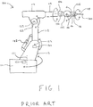
Figure 1 is a schematic illustration (not to scale) showing an example conventional manufacturing robot, or robot arm, 100. - In this example, the
robot 100 comprises six arm portions, namely afirst portion 111, asecond portion 112, athird portion 113, afourth portion 114, afifth portion 115, andsixth portion 116. Therobot 100 includes a firstrotary axis 121, a secondrotary axis 122, a thirdrotary axis 123, a fourthrotary axis 124, a fifthrotary axis 125, and a sixthrotary axis 126. Therobot 100 further comprises afirst motor 131, asecond motor 132, athird motor 133, afourth motor 134, afifth motor 135, and asixth motor 136, which separately operate a respective axis 121-126, i.e. thefirst motor 131 controls rotation about thefirst axis 121, thesecond motor 132 controls rotation about thesecond axis 122, and so on. - The operation of the individual axes 121-126 allows the robot's
end effector 140 to be repeatably and accurately positioned with respect to a workpiece. Roll, pitch and yaw of theend effector 140 also tend to be controllable. - The
robot 100 is controlled by a controller (not shown inFigure 1 ). More specifically, a controller controls operation of the motors 131-136 to move therobot 100. Also, the controller controls theend effector 140. - In this example, a
counterbalance 142 is coupled between the second andthird portions counterbalance 142 may, for example, be a hydraulic damper or a gas spring. Thecounterbalance 142 comprises a piston operating within a cylinder containing a pressurized fluid, i.e. a liquid or gas. - The
counterbalance 142 acts to support the weight of therobot 100 in operation, thereby to improve control of therobot 100. - The present inventors have realised that the mechanical structures of conventional manufacturing robots, such as the
robot 100, tend to vibrate during some machining operations, for example those involved in the construction of aircraft. Such vibrations can detrimentally affect end part surface quality and robot integrity, causing premature wear or even breaking of the cutting tool and reducing the service life of the robot. - The present inventors have further realised that passive counterbalances, such as that shown in
Figure 1 , tend to be insufficient in damping/controlling unwanted vibrations of the robot caused by dynamic machining forces experienced, for example during machining operations involved in the construction of aircraft. In other words, passive counterbalances tend to be ineffective when the dynamic parameters of the robot vary. Passive counterbalances tend to be particularly ineffective in robot machining applications in which high accuracy is desirable and when the robot is being used to machine a hard, solid surface. - The present inventors have further realised that active damping may be used to damp unwanted vibrations and reaction against dynamic forces of the robot caused by dynamic machining forces in lieu of or in addition to a passive counterbalance unit. In other words, the present inventors have realised that actively damping the vibrations of an end effector/robot by responding to the varying conditions experienced by the robot such as temperature, vibration and strain, is advantageous.
- In a first aspect, the present invention provides a robotic system comprising: a multi-axis robot; one or more sensors located on the multi-axis robot; a damping system configured to apply a resistive force to the multi-axis robot, thereby to resist movement of the multi-axis robot; and a controller coupled to the one or more sensors and the damping system. The controller is configured to: receive sensor measurements from the one or more sensors; and control, based on the received sensor measurements, the damping system thereby to control the resistive force applied by the damping system to the multi-axis robot.
- The one or more sensors may comprise one or more sensors selected from the group of sensors consisting of: vibration sensors, strain gauges, and temperature sensors. The one or more sensors may comprise one or more vibration sensors located proximate to one or more axes of the multi-axis robot. The one or more sensors may comprise one or more strain gauges located remotely from the axes of the multi-axis robot.
- The robotic system may further comprise one or more motors operable to move the multi-axis robot, and the one or more sensors may comprise one or more temperature sensors located proximate to the one or more motors.
- The damping system may comprise a hydraulic damper or gas spring.
- The robotic system may comprise a pump for pumping a fluid to the damping system. The controller may be configured to control, based on the received sensor measurements, the pump so as to pump the fluid to the damping system thereby to vary the resistive force applied by the damping system to the multi-axis robot.
- The robotic system may comprise one or more motors operable to move the multi-axis robot. The controller may be configured to control, based on the received sensor measurements, operation of the one or more motors.
- The robotic system may comprise an end effector connected to the multi-axis robot. The end effector may comprise a cutting tool. The controller may be configured to control the damping system to actively damp vibration of the end effector.
- The multi-axis robot may have six rotary axes. The robotic system may be an aerospace component manufacturing system.
- In a further aspect, the present invention provides a method of damping a multi-axis robot. The method comprising: measuring, by one or more sensors located on the multi-axis robot, one or more parameters of the multi-axis robot; and controlling, by a controller, based on sensor measurements taken by the one or more sensors, a damping system coupled to the multi-axis robot thereby to control a resistive force applied to the multi-axis robot by the damping system.
- The controlling may comprise determining, by the controller, based on the sensor measurements, a resistive force to be applied to the multi-axis robot by the damping system, and controlling, by the controller, the damping system to apply the determined resistive force to the multi-axis robot.
- The robotic system may be an aerospace component manufacturing system.
- In a further aspect, the present invention provides a method of machining a workpiece to produce an aerospace component. The method comprises: controlling a multi-axis robot to move an end effector of the multi-axis robot into contact with the workpiece and to machine the workpiece; during the machining of the workpiece, measuring, by one or more sensors located on the multi-axis robot, one or more parameters of the multi-axis robot; and controlling, by a controller, using sensor measurements of the one or more sensors, a damping system coupled to the multi-axis robot, thereby to control a resistive force applied to the multi-axis robot by the damping system so as to actively damp vibration of the end effector during the machining of the workpiece.
- In a further aspect, the present invention provides a method of damping a multi-axis robot, the method comprising: measuring, by one or more sensors located on the multi-axis robot, one or more parameters of the multi-axis robot; and controlling, by a controller, based on sensor measurements taken by the one or more sensors, a damping system coupled to the multi-axis robot thereby to control a resistive force applied to the multi-axis robot by the damping system.
- The controlling may comprise determining, by the controller, based on the sensor measurements, a resistive force to be applied to the multi-axis robot by the damping system; and controlling, by the controller, the damping system to apply the determined resistive force to the multi-axis robot.
- In a further aspect, the present invention provides a robotic system comprising: a multi-axis robot; one or more sensors located on the multi-axis robot; a damping system configured to apply a resistive force to the multi-axis robot; and a controller coupled to the one or more sensors and the damping system. The controller is configured to: receive sensor measurements from the one or more sensors; and control, based on the received sensor measurements, the damping system.
- The systems and methods described herein may be for use in the manufacture of aerospace components, preferably metal or metal alloy aerospace components. More preferably, the systems and methods described herein are methods and systems of cutting an aerospace component, such as a metal or metal alloy aerospace component.
-
-
Figure 1 is a schematic illustration (not to scale) showing a conventional manufacturing robot; and -
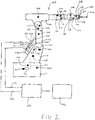
Figure 2 is a schematic illustration (not to scale) of a robot comprising an active damping system. -
Figure 2 is a schematic illustration (not to scale) of an embodiment of a robotic system comprising themulti-axis robot 100 and an active damping system. The system may be for use in the manufacture of aerospace components such as metal or metal alloy (e.g. aluminium, titanium or alloys thereof) complex thin-wall aerospace components. - The
robot 100 of the system is substantially the same as that shown inFigure 1 and described in more detail earlier above, and elements which are substantially the same as those ofFigure 1 bear identical reference numerals thereto and descriptions thereof will be omitted. - In this embodiment, the active damping system for the
robot 100 comprises adamper 150, afluid pump 200, afirst fluid line 201, asecond fluid line 202, acontroller 204, a plurality ofvibration sensors 206, a plurality ofstrain gauges 208, and a plurality oftemperature sensors 210. - In this embodiment, the
damper 150 is coupled between the second andthird portions damper 150, which may be a hydraulic damper or gas spring, comprises apiston 220 operating within acylinder 222 containing a pressurized fluid, i.e. a liquid or gas. Thepiston 220 is slidably mounted within thecylinder 222. Apiston rod 224 is rigidly fixed to thepiston 220, and extends through a bore at a first end of thecylinder 222. Thedamper 150 may comprise a seal mounted within the bore at the first end of thecylinder 222 which cooperates with thepiston rod 224 to prevent escape of fluid from thecylinder 222. In this embodiment, thesecond portion 112 is attached to thecylinder 222 of thedamper 150, via afirst coupling mechanism 226, at or proximate to a second end of thecylinder 222, which is opposite to the first end. Also, thethird portion 113 is attached to the end of thepiston rod 224 that extends from the cylinder, via asecond coupling mechanism 228. - The
pump 200 is coupled to thedamper 150 via the first andsecond fluid lines pump 200 may pump fluid (e.g. a hydraulic fluid or a pressurised gas such as nitrogen) to or from thecylinder 222 of thedamper 150 via the first andsecond fluid lines pump 200 is coupled to thecylinder 222 of thedamper 150 at a first side of thepiston 220 by thefirst fluid line 201 such that, in operation, thepump 200 may pump fluid into or out of afirst chamber 231 within thecylinder 222 of thedamper 150, thefirst chamber 231 being located at the first side of thepiston 220. Also, thepump 200 is coupled to thecylinder 222 of thedamper 150 at a second side of the piston 220 (which is opposite to the first side of the piston 220) by thesecond fluid line 202 such that, in operation, thepump 200 may pump fluid into or out of asecond chamber 232 within thecylinder 222 of thedamper 150, thesecond chamber 232 being located at the second side of thepiston 220. Thepump 200 is coupled to and controlled by thecontroller 204. - The
damper 150 is configured to exert a force on therobot 100, thereby to resist movement of therobot 100. The magnitude of the resistive force applied to therobot 100 by thedamper 150 is dependent on the fluid pressures in the first and second chambers of thedamper 150. - Each
vibration sensor 206 is mounted at a different respective location on therobot 100. Preferably, thevibration sensors 206 are located at or proximate to the axes 121-126 of therobot 100. Thevibration sensors 206 are configured to measure local vibration of therobot 100. Thevibration sensors 206 are coupled to thecontroller 204 such that vibration measurements taken by thevibration sensors 206 are sent to thecontroller 204. - Each
strain gauge 208 is mounted at a different respective location on therobot 100. Preferably, the strain gauges 208 are located on the structural portions 111-116 of therobot 100, remote or spaced apart from the axes 111-116. The strain gauges 208 are configured to measure local strains in therobot 100, which may be indicative of deflection of the portions 111-116 of therobot 100. The strain gauges 208 are coupled to thecontroller 204 such that strain measurements taken by the strain gauges 208 are sent to thecontroller 204. - Each
temperature sensor 210 is mounted at a different respective location on therobot 100. Preferably, thetemperature sensors 210 are located at or proximate to the motors 131-136. Thetemperature sensors 210 are configured to measure temperatures of different parts of therobot 100, e.g. of the motors 131-136 of therobot 100. Thetemperature sensors 210 are coupled to thecontroller 204 such that temperature measurements taken by thetemperature sensors 210 are sent to thecontroller 204. - The
controller 204 is configured to receive sensor measurements from the plurality ofvibration sensors 206, the plurality ofstrain gauges 208, and the plurality oftemperature sensors 210. The sensor measurements are the controller's input variables. Thecontroller 204 is further configured to process the received sensors measurements to determine an amount and/or a pressure of fluid that is to be contained within the first andsecond chambers cylinder 222 of thedamper 150, e.g. in order to damp or react against unwanted movement of the robot 100 (such as vibrational motion and/or deflection currently being experienced by the robot 100). In some embodiments, thecontroller 204 may be configured to, instead of or in addition to determining an amount and/or a pressure of fluid that is to be contained within the first andsecond chambers second chambers controller 204 is further configured to control thepump 200 to pump fluid (e.g. a hydraulic liquid, or a gas) into/out of the first andsecond chambers cylinder 222 of thedamper 150 such that thechambers controller 204, and/or such that the determined pressure differential is realised. - For example, in some embodiments, the
controller 204 determines, based on one or more of the received sensor measurements, a resistive force to apply to therobot 100 to damp the vibrations and deflections being experienced by the robot 100 (which may be being caused by dynamic machining forces). Thecontroller 204 may also determine fluid pressures in the first andsecond chambers cylinder 222 and/or a pressure differential therebetween that would result in the determined resistive force being applied to therobot 100. Thecontroller 204 then controls thepump 200 to pump fluid to/from the first and/orsecond chambers damper 150 is adapted to apply the determined resistive force to therobot 100, thereby to damp the vibrations and deflections being experienced by therobot 100. - The
controller 204 may be configured to increase the resistance of thedamper 150 if thevibration sensors 206 indicate an increase in vibration of therobot 100 during use, e.g. if thevibration sensors 206 indicate vibration above a threshold level. Similarly, thecontroller 204 may be configured to decrease the resistance of thedamper 150 if thevibration sensors 206 indicate low levels of vibration of therobot 100 during use, e.g. if thevibration sensors 206 indicate vibration below a threshold level. This tends to ensure compliance with robot path motion and reduce or eliminate the likelihood of the motors 131-136 being overloaded or fighting thedamper 150. - The
controller 204 may be configured to increase the resistance of thedamper 150 if the strain gauges 208 indicate an increase in deflection of therobot 100 during use, e.g. if the strain gauges 208 indicate bending above a threshold level. Similarly, thecontroller 204 may be configured to decrease the resistance of thedamper 150 if the strain gauges 208 indicate low levels of deflection of therobot 100 during use, e.g. if the strain gauges 208 indicate bending below a threshold level. Resistance may also be controlled to support the mass of the robot. - The
controller 204 may be configured to increase the resistance of thedamper 150 if thetemperature sensors 210 indicate that the motors 131-136 are operating below a threshold temperature. Similarly, thecontroller 204 may be configured to decrease the resistance of thedamper 150 if thetemperature sensors 210 indicate that the motors 131-136 are operating above a threshold temperature. This tends to ensure compliance with robot path motion and reduce or eliminate the likelihood of the motors 131-136 being overloaded or fighting thedamper 150. - Thus, the
controller 204 is particularly configured to control theactive damper 150 so that the undesirable operation and unwanted movement of therobot 100, such as excessive vibration and/or deflection, is reduced (and more preferably minimized). Thecontroller 204 may be, for example, a PID-controller, a PD controller, or a PI-controller. - The above described active damping system for the robot advantageously tends to allow for the application of variable damping and resistance to the robot. The damping system of the robot tends to be tuneable to the load being handled by the robot. This load may result from the action of machining. This tunability tends to enable undesirable influences to component accuracy and surface finish to be reduced or eliminated.
- The active damping system may advantageously react to changes, both in magnitude and direction, of the machining forces experienced by the robot during use.
- Advantageously, the above described active damping system for the robot advantageously tends to improve contact between the end effector/machining (e.g. cutting) tool of the robot and the workpiece during the machining of that workpiece. This advantageously tends to provide improved surface finish and machining accuracy. Also, this tends to improve machining efficiency by allowing for a greater depth of cut to be accurately made through greater system rigidity.
- Apparatus, including the
controller 204, for implementing the above arrangement may be provided by configuring or adapting any suitable apparatus, for example one or more computers or other processing apparatus or processors, and/or providing additional modules. The apparatus may comprise a computer, a network of computers, or one or more processors, for implementing instructions and using data, including instructions and data in the form of a computer program or plurality of computer programs stored in or on a machine-readable storage medium such as computer memory, a computer disk, ROM, PROM etc., or any combination of these or other storage media. - In the above embodiments, the robot is a six-axis robot. However, in other embodiments the robot has a different number of rotary axes about which it may be controlled to move. The robot may also include a different number of motors, i.e. other than six motors, for moving the robot. Also, in some embodiments, the robot may include one or more linear axes along which the robot may be moved. For example, the robot may be mounted to a rail or track along which it may be slid. For example the robot may have from 2 to 10 rotary axes, motors and/or linear axes.
- In the above embodiments, the damper is a hydraulic damper or gas spring. However, in other embodiments, the damper is a different type of damper, for example an electrical actuator (e.g. an electrical linear actuator).
- In the above embodiments, the robot comprises a single active damper. However, in other embodiments, the robot comprises a plurality of active dampers (e.g. two or more active dampers). In some embodiments, the robot further comprises one or more passive dampers in addition to the one or more active dampers.
- In the above embodiments, the damper is attached between the second and third portions of the robot. However, in other embodiments, one or more dampers is attached between a different pair of arm portions instead of or in addition to being attached between the second and third portions of the robot. For example, an active damper may be attached between the first and second portions, between the third and fourth portions, between the first and third portions, or between any other pair of portions.
- In the above embodiments, the damper attaches together two portions. However, in other embodiments, a damper attaches together a different number of portions, for example three portions.
- In the above embodiments, as shown in
Figure 2 , the robot comprises six vibration sensors. However, in other embodiments, the robot comprises a different number of vibration sensors, for example more than six vibration sensors. - In the above embodiments, as shown in
Figure 2 , the robot comprises strain gauges. However, in other embodiments, the robot comprises a different number of strain gauges, for example more than six strain gauges. - In the above embodiments, as shown in
Figure 2 , the robot comprises six temperature sensors. However, in other embodiments, the robot comprises a different number of vibration sensors, for example more than six temperature sensors. - In the above embodiments, the robot comprises a plurality of vibration sensors, strain gauges, and temperature sensors. However, in other embodiments, one or more of the sensors is omitted. For example, in some embodiments, one or more (e.g. all) of the temperature sensors is omitted, and the controller controls the resistance applied by the damper using some or all of the measurements taken by the vibration sensors and the strain gauges only.
- In some embodiments, the robot comprises one or more different types of sensor instead of or in addition to one or more of the vibration sensors, the strain gauges, and the temperature sensors. The controller may use measurements taken by the one or more of the different types of sensor to control the active damper. For example, the robot may include a pressure sensor configured to measure pressure of the fluid in the first chamber of the damper, a pressure sensor configured to measure pressure of the fluid in the second chamber of the damper, a pressure sensor configured to measure pressure of the fluid in the first fluid line, a pressure sensor configured to measure pressure of the fluid in the second fluid line, a flow rate sensor configured to measure a flow rate of the fluid in the first fluid line, and/or a flow rate sensor configured to measure a flow rate of the fluid in the second fluid line. The controller may control the active damper based on measurements taken by one or more of the pressure and flow rate sensors.
- In some embodiments, the controller controls the active damper based on one or more different measurements instead of or in addition to those mentioned earlier above. For example, in some embodiments, the controller controls the active damper based on an amp draw of one or more of the motors.
- In some embodiments, the controller may use measurements taken by one or more of the vibration sensors, one or more of the strain gauges, and/or one or more of the temperature sensors to control the motors.
Claims (15)
- A robotic system comprising:a multi-axis robot;one or more sensors located on the multi-axis robot;a damping system configured to apply a resistive force to the multi-axis robot, thereby to resist movement of the multi-axis robot; anda controller coupled to the one or more sensors and the damping system, the controller being configured to:receive sensor measurements from the one or more sensors; andcontrol, based on the received sensor measurements, the damping system thereby to control the resistive force applied by the damping system to the multi-axis robot.
- The robotic system of claim 1, wherein the one or more sensors comprise one or more sensors selected from the group of sensors consisting of: vibration sensors, strain gauges, and temperature sensors.
- The robotic system of claim 1 or 2, wherein the one or more sensors comprise one or more vibration sensors located proximate to one or more axes of the multi-axis robot.
- The robotic system of any of claims 1 to 3, wherein the one or more sensors comprise one or more strain gauges located remotely from the axes of the multi-axis robot.
- The robotic system of any of claims 1 to 4, wherein the robotic system further comprises one or more motors operable to move the multi-axis robot, and the one or more sensors comprise one or more temperature sensors located proximate to the one or more motors.
- The robotic system of any of claims 1 to 5, wherein the damping system comprises a hydraulic damper or gas spring.
- The robotic system of any of claims 1 to 6, further comprising a pump for pumping a fluid to the damping system, wherein the controller is configured to control, based on the received sensor measurements, the pump so as to pump the fluid to the damping system thereby to vary the resistive force applied by the damping system to the multi-axis robot.
- The robotic system of any of claims 1 to 7, wherein the robotic system comprises one or more motors operable to move the multi-axis robot, and the controller is configured to control, based on the received sensor measurements, operation of the one or more motors.
- The robotic system of any of claims 1 to 8, further comprising an end effector connected to the multi-axis robot, the end effector comprising a cutting tool.
- The robotic system of claim 9, wherein the controller is configured to control the damping system to actively damp vibration of the end effector.
- The robotic system of any of claims 1 to 10, wherein the multi-axis robot has six rotary axes.
- The robotic system of any of claims 1 to 11, wherein the robotic system is an aerospace component manufacturing system.
- A method of damping a multi-axis robot, the method comprising:measuring, by one or more sensors located on the multi-axis robot, one or more parameters of the multi-axis robot; andcontrolling, by a controller, based on sensor measurements taken by the one or more sensors, a damping system coupled to the multi-axis robot thereby to control a resistive force applied to the multi-axis robot by the damping system.
- The method of claim 13, wherein the controlling comprises:determining, by the controller, based on the sensor measurements, a resistive force to be applied to the multi-axis robot by the damping system; andcontrolling, by the controller, the damping system to apply the determined resistive force to the multi-axis robot.
- A method of machining a workpiece to produce an aerospace component, the method comprising:controlling a multi-axis robot to move an end effector of the multi-axis robot into contact with the workpiece and to machine the workpiece;during the machining of the workpiece, measuring, by one or more sensors located on the multi-axis robot, one or more parameters of the multi-axis robot; andcontrolling, by a controller, using sensor measurements of the one or more sensors, a damping system coupled to the multi-axis robot, thereby to control a resistive force applied to the multi-axis robot by the damping system so as to actively damp vibration of the end effector during the machining of the workpiece.
Priority Applications (6)
| Application Number | Priority Date | Filing Date | Title |
|---|---|---|---|
| EP18157901.2A EP3530419A1 (en) | 2018-02-21 | 2018-02-21 | Actively damped robot |
| US16/963,952 US11389964B2 (en) | 2018-02-21 | 2019-02-19 | Actively damped robot |
| GB1902243.3A GB2572848B (en) | 2018-02-21 | 2019-02-19 | Actively damped robot |
| PCT/GB2019/050432 WO2019162653A1 (en) | 2018-02-21 | 2019-02-19 | Actively damped robot |
| EP19706304.3A EP3755505B1 (en) | 2018-02-21 | 2019-02-19 | Actively damped robot |
| ES19706304T ES2965635T3 (en) | 2018-02-21 | 2019-02-19 | Robot with active damping |
Applications Claiming Priority (1)
| Application Number | Priority Date | Filing Date | Title |
|---|---|---|---|
| EP18157901.2A EP3530419A1 (en) | 2018-02-21 | 2018-02-21 | Actively damped robot |
Publications (1)
| Publication Number | Publication Date |
|---|---|
| EP3530419A1 true EP3530419A1 (en) | 2019-08-28 |
Family
ID=61256701
Family Applications (1)
| Application Number | Title | Priority Date | Filing Date |
|---|---|---|---|
| EP18157901.2A Pending EP3530419A1 (en) | 2018-02-21 | 2018-02-21 | Actively damped robot |
Country Status (1)
| Country | Link |
|---|---|
| EP (1) | EP3530419A1 (en) |
Citations (6)
| Publication number | Priority date | Publication date | Assignee | Title |
|---|---|---|---|---|
| EP1001184A2 (en) * | 1998-11-09 | 2000-05-17 | Lord Corporation | Vibration-damped machine and control method therefor |
| US20080277953A1 (en) * | 2007-05-11 | 2008-11-13 | The Boeing Company | Robotic End Effector and Clamping Method |
| WO2013184456A1 (en) * | 2012-06-08 | 2013-12-12 | Technical Manufacturing Corporation | Active vibration isolation system |
| US20160116017A1 (en) * | 2014-10-23 | 2016-04-28 | Fanuc Corporation | Positioning apparatus mounted with vibration isolators and robot |
| US20170014997A1 (en) * | 2015-07-13 | 2017-01-19 | Kuka Roboter Gmbh | Controlling A Compliant-Controlled Robot |
| CN206998973U (en) * | 2017-05-25 | 2018-02-13 | 深圳配天智能技术研究院有限公司 | Equipment for inhibiting of vibration and robot |
-
2018
- 2018-02-21 EP EP18157901.2A patent/EP3530419A1/en active Pending
Patent Citations (6)
| Publication number | Priority date | Publication date | Assignee | Title |
|---|---|---|---|---|
| EP1001184A2 (en) * | 1998-11-09 | 2000-05-17 | Lord Corporation | Vibration-damped machine and control method therefor |
| US20080277953A1 (en) * | 2007-05-11 | 2008-11-13 | The Boeing Company | Robotic End Effector and Clamping Method |
| WO2013184456A1 (en) * | 2012-06-08 | 2013-12-12 | Technical Manufacturing Corporation | Active vibration isolation system |
| US20160116017A1 (en) * | 2014-10-23 | 2016-04-28 | Fanuc Corporation | Positioning apparatus mounted with vibration isolators and robot |
| US20170014997A1 (en) * | 2015-07-13 | 2017-01-19 | Kuka Roboter Gmbh | Controlling A Compliant-Controlled Robot |
| CN206998973U (en) * | 2017-05-25 | 2018-02-13 | 深圳配天智能技术研究院有限公司 | Equipment for inhibiting of vibration and robot |
Similar Documents
| Publication | Publication Date | Title |
|---|---|---|
| US11389964B2 (en) | Actively damped robot | |
| US12151378B2 (en) | Vibration reduction system for precision robotics applications | |
| JP6374439B2 (en) | Abnormality detection device and abnormality detection method for joint part of parallel link robot | |
| JP6778050B2 (en) | Machine Tools | |
| Brecher et al. | Avoiding chatter by means of active damping systems for machine tools | |
| EP4096873B1 (en) | Apparatus for active contact force control in machining and handling operations | |
| Fok et al. | Position control and repeatability of a pneumatic rodless cylinder system for continuous positioning | |
| Chen et al. | Sensor-based force decouple controller design of macro–mini manipulator | |
| JP2024510677A (en) | Force-controlled handling equipment for robot-assisted surface machining | |
| Dindorf et al. | Control of integrated electro-hydraulic servo-drives in a translational parallel manipulator | |
| KR102591945B1 (en) | A processing apparatus for implementing a posture maintaining the rigidity of the robot, and a processing method for implementing the posture maintaining the rigidity of the robot using the same | |
| He et al. | Design of a novel force controlled polishing device based on a coupled active-passive compliant mechanism | |
| CN112847332A (en) | Working mechanism | |
| US7971496B2 (en) | Method for determining the elastic deformation of components | |
| CN101137942B (en) | Method for determining the elastic deformation of a component | |
| Warkentin et al. | Variable stiffness control of a single-link flexible robotic arm | |
| Bernzen | On vibration damping of hydraulically driven flexible robots | |
| SK289104B6 (en) | Robotic machining head | |
| Zhu et al. | Tip tracking control of a linear-motor-driven flexible manipulator with controllable damping | |
| Shim et al. | A novel vibration suppressing method for robotic machining by inertial moment actuator using gyroscopic spindle | |
| Urrutia et al. | Performance of the counterbalance systems in heavy industrial robots under cyclic operation | |
| Kärkkäinen et al. | Modal space control of manipulator vibrational motion | |
| van der Weij | Active vibration control in hydraulically supported machinery | |
| Chung et al. | Modeling and control of a new robotic deburring system | |
| Cardozo et al. | Numerical and Experimental Analysis of a Parallel 2-DOF Manipulator |
Legal Events
| Date | Code | Title | Description |
|---|---|---|---|
| PUAI | Public reference made under article 153(3) epc to a published international application that has entered the european phase |
Free format text: ORIGINAL CODE: 0009012 |
|
| STAA | Information on the status of an ep patent application or granted ep patent |
Free format text: STATUS: THE APPLICATION HAS BEEN PUBLISHED |
|
| AK | Designated contracting states |
Kind code of ref document: A1 Designated state(s): AL AT BE BG CH CY CZ DE DK EE ES FI FR GB GR HR HU IE IS IT LI LT LU LV MC MK MT NL NO PL PT RO RS SE SI SK SM TR |
|
| AX | Request for extension of the european patent |
Extension state: BA ME |