EP3530395A1 - Ac pulse arc welding control method - Google Patents
Ac pulse arc welding control method Download PDFInfo
- Publication number
- EP3530395A1 EP3530395A1 EP17864512.3A EP17864512A EP3530395A1 EP 3530395 A1 EP3530395 A1 EP 3530395A1 EP 17864512 A EP17864512 A EP 17864512A EP 3530395 A1 EP3530395 A1 EP 3530395A1
- Authority
- EP
- European Patent Office
- Prior art keywords
- period
- electrode
- positive polarity
- current
- negative polarity
- Prior art date
- Legal status (The legal status is an assumption and is not a legal conclusion. Google has not performed a legal analysis and makes no representation as to the accuracy of the status listed.)
- Granted
Links
Images



Classifications
-
- B—PERFORMING OPERATIONS; TRANSPORTING
- B23—MACHINE TOOLS; METAL-WORKING NOT OTHERWISE PROVIDED FOR
- B23K—SOLDERING OR UNSOLDERING; WELDING; CLADDING OR PLATING BY SOLDERING OR WELDING; CUTTING BY APPLYING HEAT LOCALLY, e.g. FLAME CUTTING; WORKING BY LASER BEAM
- B23K9/00—Arc welding or cutting
- B23K9/09—Arrangements or circuits for arc welding with pulsed current or voltage
- B23K9/091—Arrangements or circuits for arc welding with pulsed current or voltage characterised by the circuits
- B23K9/092—Arrangements or circuits for arc welding with pulsed current or voltage characterised by the circuits characterised by the shape of the pulses produced
-
- B—PERFORMING OPERATIONS; TRANSPORTING
- B23—MACHINE TOOLS; METAL-WORKING NOT OTHERWISE PROVIDED FOR
- B23K—SOLDERING OR UNSOLDERING; WELDING; CLADDING OR PLATING BY SOLDERING OR WELDING; CUTTING BY APPLYING HEAT LOCALLY, e.g. FLAME CUTTING; WORKING BY LASER BEAM
- B23K9/00—Arc welding or cutting
- B23K9/095—Monitoring or automatic control of welding parameters
-
- B—PERFORMING OPERATIONS; TRANSPORTING
- B23—MACHINE TOOLS; METAL-WORKING NOT OTHERWISE PROVIDED FOR
- B23K—SOLDERING OR UNSOLDERING; WELDING; CLADDING OR PLATING BY SOLDERING OR WELDING; CUTTING BY APPLYING HEAT LOCALLY, e.g. FLAME CUTTING; WORKING BY LASER BEAM
- B23K9/00—Arc welding or cutting
- B23K9/06—Arrangements or circuits for starting the arc, e.g. by generating ignition voltage, or for stabilising the arc
- B23K9/073—Stabilising the arc
-
- B—PERFORMING OPERATIONS; TRANSPORTING
- B23—MACHINE TOOLS; METAL-WORKING NOT OTHERWISE PROVIDED FOR
- B23K—SOLDERING OR UNSOLDERING; WELDING; CLADDING OR PLATING BY SOLDERING OR WELDING; CUTTING BY APPLYING HEAT LOCALLY, e.g. FLAME CUTTING; WORKING BY LASER BEAM
- B23K9/00—Arc welding or cutting
- B23K9/06—Arrangements or circuits for starting the arc, e.g. by generating ignition voltage, or for stabilising the arc
- B23K9/073—Stabilising the arc
- B23K9/0732—Stabilising of the arc current
-
- B—PERFORMING OPERATIONS; TRANSPORTING
- B23—MACHINE TOOLS; METAL-WORKING NOT OTHERWISE PROVIDED FOR
- B23K—SOLDERING OR UNSOLDERING; WELDING; CLADDING OR PLATING BY SOLDERING OR WELDING; CUTTING BY APPLYING HEAT LOCALLY, e.g. FLAME CUTTING; WORKING BY LASER BEAM
- B23K9/00—Arc welding or cutting
- B23K9/09—Arrangements or circuits for arc welding with pulsed current or voltage
-
- B—PERFORMING OPERATIONS; TRANSPORTING
- B23—MACHINE TOOLS; METAL-WORKING NOT OTHERWISE PROVIDED FOR
- B23K—SOLDERING OR UNSOLDERING; WELDING; CLADDING OR PLATING BY SOLDERING OR WELDING; CUTTING BY APPLYING HEAT LOCALLY, e.g. FLAME CUTTING; WORKING BY LASER BEAM
- B23K9/00—Arc welding or cutting
- B23K9/095—Monitoring or automatic control of welding parameters
- B23K9/0956—Monitoring or automatic control of welding parameters using sensing means, e.g. optical
-
- B—PERFORMING OPERATIONS; TRANSPORTING
- B23—MACHINE TOOLS; METAL-WORKING NOT OTHERWISE PROVIDED FOR
- B23K—SOLDERING OR UNSOLDERING; WELDING; CLADDING OR PLATING BY SOLDERING OR WELDING; CUTTING BY APPLYING HEAT LOCALLY, e.g. FLAME CUTTING; WORKING BY LASER BEAM
- B23K9/00—Arc welding or cutting
- B23K9/10—Other electric circuits therefor; Protective circuits; Remote controls
- B23K9/1006—Power supply
-
- B—PERFORMING OPERATIONS; TRANSPORTING
- B23—MACHINE TOOLS; METAL-WORKING NOT OTHERWISE PROVIDED FOR
- B23K—SOLDERING OR UNSOLDERING; WELDING; CLADDING OR PLATING BY SOLDERING OR WELDING; CUTTING BY APPLYING HEAT LOCALLY, e.g. FLAME CUTTING; WORKING BY LASER BEAM
- B23K9/00—Arc welding or cutting
- B23K9/16—Arc welding or cutting making use of shielding gas
- B23K9/173—Arc welding or cutting making use of shielding gas and of a consumable electrode
Definitions
- the present invention relates to an AC pulse arc welding control method for controlling welding which is performed by feeding a welding wire, and applying an electrode negative polarity base current during an electrode negative polarity base period, then applying an electrode negative polarity peak current during an electrode negative polarity peak period, and then applying an electrode positive polarity current during an electrode positive polarity period, to repeatedly apply these welding currents.
- the welding is performed by repeating the application of a peak current and a base current during an electrode positive polarity period and the application of a base current during an electrode negative polarity period, as one cycle.
- an electrode negative polarity current ratio which is a ratio of the current during the electrode negative polarity period to an average value of the welding current, is changed by adjusting the electrode negative polarity period so that the heat input to a base material can be controlled.
- the bead shape such as a penetration depth and a reinforcement height according to a workpiece can be optimized by changing the electrode negative polarity current ratio.
- the electrode negative polarity current ratio is used in a range of about 0% to 30%.
- the electrode negative polarity current ratio of 0% indicates DC pulse arc welding.
- a bead shape with a small dilution ratio may be formed by reducing a penetration portion and enlarging a reinforcement portion.
- a bead shape with a small dilution ratio is required in order to fill the gap with molten metal and reduce penetration.
- a bead shape with a small dilution ratio is required in order to fill the gap with molten metal and reduce penetration.
- an AC pulse arc welding method is used in which the welding is performed by repeating the application of the peak current and base current during the electrode positive polarity period and the application of the peak current and the base current during the electrode negative polarity period as one cycle.
- a technique in the conventional art see Patent Literature 1 will be described.
- the welding current and the welding voltage in the electrode negative polarity period may be negative values and when describing the magnitudes of the values, the magnitudes of the values mean the absolute values thereof.
- the expression of "rising and falling" means that the absolute value of the welding current or the welding voltage increases or decreases.
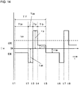
- Fig. 14 is a waveform diagram of a welding current Iw showing an AC pulse arc welding control method in the conventional art.
- Fig. 14 also shows an electrode positive polarity EP from 0A to an upper side, and an electrode negative polarity EN from 0A to a lower side.
- Fig. 14 shows a case where an electrode negative polarity current ratio is set larger than the normal range (about 0% to 30%).
- a high voltage is applied between a welding wire and a base material for a short time during the polarity switching.
- description will be made with reference to Fig. 14 .
- an electrode negative polarity base current Ibn less than a critical value is applied.
- an electrode negative polarity peak current Ipn having a value larger than the electrode negative polarity base current Ibn is applied.
- the polarity is inverted.
- an electrode positive polarity peak current Ip equal to or larger than a critical value is applied.
- an electrode positive polarity base current Ib less than a critical value is applied.
- the period from time points t5 to t6 is the electrode negative polarity base period Tbn again, the period from time points t6 to t7 is the electrode negative polarity peak period Tpn again, and the period from time points t7 to t8 is the electrode positive polarity peak period Tp again.
- the period from time points t1 to t5 is one pulse cycle Tf.
- the period from the time points t1 to t3 is an electrode negative polarity period Ten, and the period from the time points t3 to t5 is an electrode positive polarity period Tep.
- the electrode negative polarity base current Ibn and the electrode negative polarity peak current Ipn belong to an electrode negative polarity current Ien
- the electrode positive polarity peak current Ip and the electrode positive polarity base current Ib belong to an electrode positive polarity current Iep.
- the electrode positive polarity base period Tb may be deleted.
- the electrode negative polarity base period Tbn ⁇ the electrode negative polarity peak period Tpn ⁇ the electrode positive polarity peak period Tp ⁇ the electrode negative polarity base period Tbn is repeated.
- the electrode positive polarity peak period Tp, the electrode positive polarity peak current Ip, the electrode negative polarity peak period Tpn, the electrode negative polarity peak current Ipn, the electrode negative polarity base current Ibn, and the electrode positive polarity base current Ib are preset to appropriate values.
- the length of the pulse cycle Tf is subjected to feedback control (arc length control), such that the average value of the absolute values of the welding voltages is equal to a predetermined voltage setting value.
- the electrode positive polarity base period Tb or the electrode negative polarity base period Tbn is changed by the feedback control.
- the setting value of each parameter is, for example, as follows.
- Tp 1.7 ms
- Ip 500 A
- Tpn 2.5 ms
- Ipn 300 A
- Ib 50 A
- Ibn 70 A.
- Tb 0 to 4.0 ms.
- Tb 0 there is no electrode positive polarity base period.
- the range of the Tbn being subjected to the feedback control is about 1 ms to 10 ms.
- the droplets transfer when the electrode positive polarity peak period Tp comes to an end, i.e., at the time point t4. Since during the electrode positive polarity base period Tb from the time points t4 to t5, a small current less than the critical value is applied, and the polarity is the electrode positive polarity EP, a tip of the welding wire hardly melts, and almost no droplet is formed.
- the tip of the welding wire is melted, and small droplets are formed. Since during the electrode negative polarity peak period Tpn from the time points t6 to t7, the electrode negative polarity peak current Ipn having a large current value is applied, the droplets grow rapidly and become large. In the latter half of this period, constrictions are gradually formed in the droplets, but usually no droplets transfer due to the large droplet size.
- Patent Literature 1 JP-A-2014-34049
- the droplets of the tip of the welding wire gradually become large during the electrode negative polarity base period Tbn, and grows rapidly and become large when entering the electrode negative polarity peak period Tpn.
- the electrode negative polarity peak current Ipn having a larger current value is continuously applied during the electrode negative polarity peak period Tpn, an arc pressure and a strong repulsive force due to metal vapor ejected from the molten pool act on the droplets.
- the growth of the droplets is unstable, and the size of the formed droplets varies.
- the droplet transfer is unstable during the electrode positive polarity peak period Tp.
- an object of the present invention is to provide an AC pulse arc welding control method capable of stabilizing the growth of droplets during an electrode negative polarity peak period.
- the present disclosure relates to an AC pulse arc welding control method for controlling welding which is performed by feeding a welding wire, and applying an electrode negative polarity base current during an electrode negative polarity base period, then applying an electrode negative polarity peak current during an electrode negative polarity peak period, and then applying an electrode positive polarity current during an electrode positive polarity period, to repeatedly apply these welding currents, wherein the electrode negative polarity peak period includes a rising period, a peak period, and a falling period, and a time ratio of the peak period to the electrode negative polarity peak period is less than 20%.
- the falling period is a period twice or more longer than the rising period.
- the welding current continuously decreases during the falling period.
- an absolute value of the welding current during the falling period is a constant value smaller than that during the peak period.
- the welding current decreases so that an absolute value of a change ratio of the welding current continuously increases during the falling period.
- the electrode positive polarity period includes an electrode positive polarity peak period during which an electrode positive polarity peak current is applied, the electrode positive polarity peak period includes an electrode positive polarity rising period, an electrode positive polarity maximum value period, and an electrode positive polarity falling period, and a time ratio of the electrode positive polarity maximum value period to the electrode positive polarity peak period is less than 20%.
- the welding current increases so that an absolute value of a change ratio of the welding current continuously decreases during the electrode positive polarity rising period, and the welding current decreases so that an absolute value of a change ratio of the welding current continuously decreases during the electrode positive polarity falling period.
- the electrode positive polarity period includes an electrode positive polarity peak period during which an electrode positive polarity peak current is applied, the electrode positive polarity peak period includes an electrode positive polarity rising period, an electrode positive polarity maximum value period, and an electrode positive polarity falling period, and the electrode positive polarity maximum value period includes a first maximum value period during which a first maximum current is applied and a second maximum value period during which a second maximum current is applied, and the first maximum current is larger than the second maximum current.
- the electrode negative polarity base period is shifted to the electrode negative polarity peak period.
- the growth of droplets can be stabilized during an electrode negative polarity peak period in AC pulse arc welding.
- a welding current waveform in an AC pulse arc welding control method is same as that in Fig. 14 except for the waveform of the electrode negative polarity peak current Ipn. That is, there are a case of taking an electrode negative polarity base period Tbn ⁇ an electrode negative polarity peak period Tpn ⁇ an electrode positive polarity peak period Tp ⁇ an electrode positive polarity base period Tb as one pulse cycle Tf, and a case of taking the electrode negative polarity base period Tbn ⁇ the electrode negative polarity peak period Tpn ⁇ the electrode positive polarity peak period Tp as one pulse cycle Tf.
- the waveform of the electrode negative polarity peak current Ipn will be described.
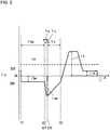
- Fig. 1 is a first welding current waveform diagram showing the waveform of the electrode negative polarity peak current Ipn in the AC pulse arc welding control method according to the first embodiment of the present invention. Welding current waveforms of other periods are the same as Fig. 14 .
- a period before a time point t2 is the electrode negative polarity base period Tbn
- a period before a time point t3 is the electrode positive polarity peak period Tp whose polarity is inverted.
- description will be made with reference to Fig. 1 .
- the electrode negative polarity base period Tbn is switched to the electrode negative polarity peak period Tpn, and the electrode negative polarity peak current Ipn starts to be applied.
- the electrode negative polarity peak period Tpn includes a rising period Tu from time points t2 to t21, a peak period Ta from time points t21 to t22, and a falling period Td from time points t22 to t3.
- the current linearly increases from the electrode negative polarity base current Ibn to a peak value.
- the peak value is maintained.
- the current linearly decreases from the peak value to a predetermined polarity switching current value (about 50 A).
- the polarity of the electrode negative polarity peak current Ipn is switched from an electrode negative polarity EN to an electrode positive polarity EP in a state of the polarity switching current value.
- a high voltage of several hundred volts is applied between a welding wire and a base material.
- the above peak value is set to substantially the same value as the peak value of the electrode negative polarity peak current Ipn in the case of the conventional art shown in Fig. 14 .
- an integrated value of the electrode negative polarity peak current Ipn during the electrode negative polarity peak period Tpn is set to substantially the same value as an integrated value in the case of a rectangular wave in the conventional art shown in Fig. 14 .
- a time ratio of the peak period Ta to the electrode negative polarity peak period Tpn is set to be less than 20%. That is, Ta is set to satisfy (Ta/Tpn) ⁇ 100 ⁇ 20. Accordingly, an arc pressure and a repulsive force due to metal vapor ejected from a molten pool, which act on droplets, can be alleviated. As a result, the growth of the droplets can be stabilized during the electrode negative polarity peak period Tpn and droplets of a desired size can always be formed.
- the time ratio during the peak period Ta is more than 20%, the repulsive force is strong, and the growth of the droplets is unstable. It is further desired that the time ratio during the peak period Ta is less than 10%. In this way, the repulsive force is further weakened and the growth of the droplets is further stabilized.
- the integrated value of the electrode negative polarity peak current Ipn is substantially the same value as that in the case of the rectangular wave in the conventional art, the size of the formed droplets is equal.
- the falling period Td is set to a period twice or more longer than the rising period Tu in the first embodiment. In this way, a falling speed of the heat input to the droplets is slow and the growth of the droplets is more stabilized. It is further desired that the falling period Td is set to a period three times or more longer than the rising period Tu in the first embodiment. In this way, the falling speed of the heat input to the droplets is slower and the growth of the droplets is further stabilized.
- Fig. 2 is a second welding current waveform diagram showing a waveform of the electrode negative polarity peak current Ipn in the AC pulse arc welding control method according to the first embodiment of the present invention.
- Fig. 2 shows almost a sawtooth wave. Even when such a waveform is set, the same effect as in Fig. 1 can be obtained.
- Fig. 3 is a third welding current waveform diagram showing a waveform of the electrode negative polarity peak current Ipn in the AC pulse arc welding control method according to the first embodiment of the present invention.
- Fig. 3 shows almost a stepwise waveform of two stages. Even when such a waveform is set, the same effect as in Fig. 1 can be obtained.
- Fig. 4 is a fourth welding current waveform diagram showing a waveform of the electrode negative polarity peak current Ipn in the AC pulse arc welding control method according to the first embodiment of the present invention.
- Fig. 4 shows a rising period Tu and a peak period Ta same as those in Fig. 1 .
- the current during the falling period Td decreases not linearly but curvedly.
- the "curvedly” indicates a state where the welding current decreases so that an absolute value of a change ratio of the welding current continuously increases.
- the growth of the droplets is more stabilized than in the case of Fig. 1 since the change ratio when the absolute value of the current value is large is small.
- Fig. 5 is a block diagram of a welding power source for performing the AC pulse arc welding control method according to the first embodiment of the present invention described above with reference to Figs. 1 to 4 .
- Fig. 5 shows a case where the electrode negative polarity base period Tbn is changed by feedback control and the electrode positive polarity base period Tb is a predetermined value.
- a high voltage application circuit during the above polarity switching is omitted.
- each block will be described below with reference to Fig. 5 .
- An inverter circuit INV receives an input from a 3-phase 200 V AC commercial power source (not shown) or the like, performs inverter control on a rectified and smoothed DC voltage by pulse width modulation control based on a current error amplification signal Ei to be described later, and outputs a high frequency AC voltage.
- An inverter transformer INT steps down the high frequency AC voltage to a voltage value suitable for arc welding.
- Secondary rectifiers D2a to D2d rectify the step-down high frequency AC voltage to a DC voltage.
- An electrode positive polarity transistor PTR is turned on by an electrode positive polarity drive signal Pd to be described later, and in this case, the output of the welding power source is the electrode positive polarity EP.
- An electrode negative polarity transistor NTR is turned on by an electrode negative polarity drive signal Nd to be described later, and in this case, the output of the welding power source is the electrode negative polarity EN.
- a reactor WL smoothes the output with ripples.
- a welding wire 1 is fed inside a welding torch 4 by the rotation of a feed roll 5 coupled to a wire feed motor WM, and an arc 3 is generated between the welding wire 1 and a base material 2.
- a welding voltage Vw is applied between the welding wire 1 and the base material 2, and a welding current Iw is supplied.
- a voltage detection circuit VD detects the welding voltage Vw and outputs a voltage detection signal Vd.
- a voltage averaging circuit VAV averages absolute values of the voltage detection signal Vd and outputs a voltage average value signal Vav.
- a voltage setting circuit VR outputs a predetermined voltage setting signal Vr.
- a voltage error amplification circuit EV amplifies an error between the voltage setting signal Vr and the voltage average value signal Vav and outputs a voltage error amplification signal Ev.
- a voltage and frequency conversion circuit VF converts the voltage error amplification signal Ev into a signal having a frequency proportional to the voltage error amplification signal Ev, and outputs a pulse cycle signal Tf which is at a high level only for a short time for each frequency.
- the pulse cycle signal Tf is a trigger signal which is at a high level for a short time for each pulse cycle.
- An electrode negative polarity peak period setting circuit TPNR outputs a predetermined electrode negative polarity peak period setting signal Tpnr.
- An electrode positive polarity peak period setting circuit TPR outputs a predetermined electrode positive polarity peak period setting signal Tpr.
- An electrode positive polarity base period setting circuit TBR outputs a predetermined electrode positive polarity base period setting signal Tbr.
- a timer circuit TM receives the pulse cycle signal Tf, the electrode negative polarity peak period setting signal Tpnr, the electrode positive polarity peak period setting signal Tpr and the electrode positive polarity base period setting signal Tbr as inputs and then outputs a timer signal Tm. Every time the pulse cycle signal Tf changes to a high level for a short time, the value of the timer signal becomes 1 during a period determined by the electrode negative polarity peak period setting signal Tpnr. Then, the value of the timer signal becomes 2 during a period determined by the electrode positive polarity peak period setting signal Tpr. Then, the value of the timer signal becomes 3 during a period determined by the electrode positive polarity base period setting signal Tbr. Thereafter, the value of the timer signal becomes 4 during the electrode negative polarity base period.
- An electrode negative polarity peak current setting circuit IPNR stores the waveforms shown in Figs. 1 to 4 , and outputs an electrode negative polarity peak current setting signal Ipnr by selecting one of the waveforms.
- An electrode positive polarity peak current setting circuit IPR outputs a predetermined electrode positive polarity peak current setting signal Ipr.
- An electrode positive polarity base current setting circuit IBR outputs a predetermined electrode positive polarity base current setting signal Ibr.
- An electrode negative polarity base current setting circuit IBNR outputs a predetermined electrode negative polarity base current setting signal Ibnr.
- a current detection circuit ID detects the absolute value of the welding current Iw and outputs a current detection signal Id.
- a current error amplification circuit EI amplifies an error between the current setting signal Ir and the current detection signal Id and outputs a current error amplification signal Ei.
- a feed speed setting circuit FR outputs a predetermined feed speed setting signal Fr.
- a feed control circuit FC receives the feed speed setting signal Fr as an input and outputs a feed control signal Fc for feeding the welding wire 1 at a feed speed Fw corresponding to the value of the feed speed setting signal Fr to the wire feed motor WM.
- the electrode positive polarity base period setting signal Tbr may be set to be 0.
- a welding current waveform in an AC pulse arc welding control method is same as that in Fig. 14 except for the waveforms of the electrode negative polarity peak current Ipn in Figs. 1 to 4 and an electrode positive polarity peak current Ip to be described later. That is, there are a case of taking an electrode negative polarity base period Tbn ⁇ an electrode negative polarity peak period Tpn ⁇ an electrode positive polarity peak period Tp ⁇ an electrode positive polarity base period Tb as one pulse cycle Tf, and a case of taking the electrode negative polarity base period Tbn ⁇ the electrode negative polarity peak period Tpn ⁇ the electrode positive polarity peak period Tp as one pulse cycle Tf.
- the waveform of the electrode positive polarity peak current Ip will be described.
- Fig. 6 is a first welding current waveform diagram showing a waveform of the electrode positive polarity peak current Ip in the AC pulse arc welding control method according to the second embodiment of the present invention. Welding current waveforms of other periods are the same as in the first embodiment.
- a period before the time point t3 is the electrode negative polarity peak period Tpn
- a period before the time point t4 is the electrode positive polarity base period Tb.
- description will be made with reference to Fig. 6 .
- the electrode negative polarity peak period Tpn is switched to the electrode positive polarity peak period Tp, and the electrode positive polarity peak current Ip starts to be applied.
- the electrode positive polarity peak period Tp includes an electrode positive polarity rising period Tpu from time points t3 to t31, an electrode positive polarity maximum value period Tpa from time points t31 to t32, and an electrode positive polarity falling period Tpd from time points t32 to t4.
- the current linearly increases from the polarity switching current value to a maximum value.
- the electrode positive polarity maximum value period Tpa from the time points t31 to t32, the maximum value is maintained.
- the electrode positive polarity falling period Tpd from the time points t32 to t4 the current linearly increases from the maximum value to the electrode positive polarity base current Ib.
- the above maximum value is set to a value smaller by about 100 A than the maximum value of the electrode positive polarity peak current Ip in the case of the conventional art shown in Fig. 14 .
- an integrated value of the electrode positive polarity peak current Ip during the electrode positive polarity peak period Tp is set to substantially the same value as the integrated value in the case of the rectangular wave in the conventional art shown in Fig. 14 .
- a time ratio of electrode positive polarity peak period Tp to the electrode positive polarity maximum value period Tpa is set to be less than 20%. That is, Tpa is set to satisfy (Tpa/Tp) ⁇ 100 ⁇ 20. Accordingly, the arc pressure acting on the droplets can be alleviated. As a result, since burn-through can be prevented when the base material is a thin sheet, high quality thin sheet welding can be obtained. Particularly, when the material of the base material is stainless steel, the above effect is significant. Therefore, it is desirable to have this waveform when performing stainless steel welding.
- the time ratio of the electrode positive polarity maximum value period Tpa is more than 20%, the arc pressure is strong, and burn-through may occur. It is desirable that the time ratio of the electrode positive polarity maximum value period Tpa is less than 10%. In this way, the arc pressure is further weakened and the probability of occurrence of burn-through is lowered.
- the integrated value of the electrode positive polarity peak current Ip is substantially the same value as that in the case of the rectangular wave in the conventional art, the size of the formed droplets is equal.
- Tpu 1.5 ms to 2.0 ms
- Tpa 0.2 ms
- Tpd 1.5 ms to 2.0 ms
- maximum value of Ip 300 A to 400 A.
- Fig. 7 is a second welding current waveform diagram showing a waveform of the electrode positive polarity peak current Ip in the AC pulse arc welding control method according to the second embodiment of the present invention.
- Fig. 7 corresponds to Fig. 6 described above, in which the waveforms of the electrode positive polarity rising period Tpu from times t3 to t31 and the electrode positive polarity falling period Tpd from times t32 to t4 are different from those in Fig. 6 .
- the electrode positive polarity maximum value period Tpa from time points t31 to t 32 is the same as that in Fig. 6 .
- the points different from those in Fig. 6 will be mainly described.
- the welding current increases so that the absolute value of the change ratio of the welding current Iw continuously decreases from the above polarity switching current value to the maximum value.
- the electrode positive polarity maximum value period Tpa from the time points t31 to t32, the maximum value is maintained.
- the electrode positive polarity falling period Tpd from the time points t32 to t4 the welding current decreases so that the absolute value of the change ratio of the welding current Iw continuously decreases from the maximum value to the electrode positive polarity base current Ib.
- the above maximum value is set to a value smaller by about 100 A than the maximum value of the electrode positive polarity peak current Ip in the case of the conventional art shown in Fig. 14 .
- an integrated value of the electrode positive polarity peak current Ip during the electrode positive polarity peak period Tp is set to be substantially the same value as the integrated value in the case of the rectangular wave in the conventional art shown in Fig. 14 .
- a time ratio of electrode positive polarity peak period Tp to the electrode positive polarity maximum value period Tpa is set to be less than 20%. That is, Tpa is set to satisfy (Tpa/Tp) ⁇ 100 ⁇ 20. Accordingly, the arc pressure acting on the droplets can be alleviated. As a result, since burn-through can be prevented when the base material is a thin sheet, high quality thin sheet welding can be obtained. Particularly, when the material of the base material is stainless steel, the above effect is significant. Therefore, it is desirable to have this waveform when performing stainless steel welding.
- the time ratio of the electrode positive polarity maximum value period Tpa is more than 20%, the arc pressure is strong, and burn-through may occur. It is desirable that the time ratio of the electrode positive polarity maximum value period Tpa is less than 10%. In this way, the arc pressure is further weakened and the probability of occurrence of burn-through is lowered.
- the welding current Iw during the electrode positive polarity rising period Tpu changes such that the absolute value of the change ratio decreases as the current value increases.
- the change of the arc pressure is further alleviated.
- the welding current Iw during the electrode positive polarity falling period Tpd has a large absolute value of the change ratio when the current value is large.
- the directivity of the arc is strong, and arc instability due to magnetic blowing or the like can be suppressed.
- the absolute value of the change ratio decreases as the current value decreases.
- the arc breakage due to undershoot can be suppressed.
- stainless steel can be welded with higher quality.
- Fig. 8 is a third welding current waveform diagram showing a waveform of the electrode positive polarity peak current Ip in the AC pulse arc welding control method according to the second embodiment of the present invention. Welding current waveforms of other periods are the same as in the first embodiment.
- a period before the time point t3 is the electrode negative polarity peak period Tpn
- a period before the time point t4 is the electrode positive polarity base period Tb.
- description will be made with reference to Fig. 8 .
- the electrode negative polarity peak period Tpn is switched to the electrode positive polarity peak period Tp, and the electrode positive polarity peak current Ip starts to be applied.
- the electrode positive polarity peak period Tp includes an electrode positive polarity rising period Tpu from time points t3 to t31, an electrode positive polarity maximum value period Tpa from time points t31 to t32, and an electrode positive polarity falling period Tpd from time points t32 to t4.
- the electrode positive polarity maximum value period Tpa from the time points t31 to t32 includes a first maximum value period during which a first maximum current is applied and a second maximum value period during which a second maximum current is applied.
- the first maximum current is larger than the second maximum current.
- the difference between the first maximum value and the second maximum value is set to be about 50 A to 100 A.
- the average value of the first maximum value and the second maximum value is set to substantially the same value as in the case of the conventional art shown in Fig. 14 .
- an integrated value of the electrode positive polarity peak current Ip during the electrode positive polarity peak period Tp is set to be substantially the same value as the integrated value in the case of the rectangular wave in the conventional art shown in Fig. 14 .
- the droplet transfer state can be stabilized by setting the welding current Iw during the electrode positive polarity maximum value period Tpa to have a stepwise waveform.
- the above effect is more significant. Therefore, steel welding can be performed with higher quality.
- Fig. 9 is a block diagram of a welding power source for performing the AC pulse arc welding control method according to the second embodiment of the present invention described above with reference to Figs. 6 to 8 .
- Fig. 9 corresponds to Fig. 5 described above, in which the same reference numerals are attached to the same blocks, and description thereof will not be repeated.
- the electrode positive polarity peak current setting circuit IPR of Fig. 5 is replaced by a second electrode positive polarity peak current setting circuit IPR2.
- the block will be described below with reference to Fig. 9 .
- the second electrode positive polarity peak current setting circuit IPR2 stores the waveforms shown in Figs. 6 to 8 , and outputs the electrode positive polarity peak current setting signal Ipr by selecting one of the waveforms.
- Fig. 10 is a waveform diagram of current, voltage, and feed speed showing the AC pulse arc welding control method according to the third embodiment of the present invention.
- A) of Fig. 10 shows the change of the welding current Iw with time
- B) of Fig. 10 shows the change of the welding voltage Vw with time
- C) of Fig. 10 shows the change of the feed speed Fw of the welding wire with time.
- a period from time points t1 to t2 is the electrode negative polarity base period Tbn
- a period from time points t2 to t3 is the electrode negative polarity peak period Tpn
- a period from time points t3 to t4 is the electrode positive polarity peak period Tp
- a period from time points t4 to t5 is the electrode positive polarity base period Tb
- a period from time points t5 to t6 is the electrode negative polarity base period Tbn again.
- the waveform of the electrode negative polarity peak current Ipn during the electrode negative polarity peak period Tpn from the time points t2 to t3 is the same as one of the above waveforms in Figs. 1 to 4 .
- (A) of Fig. 10 shows the waveform of Fig. 1 .
- the welding voltage Vw has a waveform similar to the current waveform substantially proportional to the arc length.
- the feed speed Fw is a steady feed speed having a predetermined constant value.
- the waveform of the electrode positive polarity peak current Ip during the electrode positive polarity peak period Tp from the time points t3 to t4 is the same as one of the above waveforms in Figs. 6 to 8 .
- (A) of Fig. 10 shows the waveform of Fig. 6 .
- the welding voltage Vw has a waveform similar to the current waveform substantially proportional to the arc length.
- the feed speed Fw is the above steady feed speed.
- a predetermined electrode positive polarity base current Ib is applied.
- the welding voltage Vw is an arc voltage value substantially proportional to the arc length.
- the feed speed Fw is the above steady feed speed.
- the operation during the electrode negative polarity base period Tbn from the time points t5 to t6 is as follows. During a period from time points t5 to t51, a predetermined electrode negative polarity base current Ibn is applied. As shown in (B) of Fig. 10 , the welding voltage Vw is an arc voltage value substantially proportional to the arc length. As shown in (C) of Fig. 10 , the feed speed Fw is the above steady feed speed.
- a short circuit between the welding wire and the base material occurs at the time point t51.
- the welding current Iw gradually increases as shown in (A) of Fig. 10 , the short circuit is released earlier, and the arc is regenerated.
- the welding voltage Vw has a short-circuit voltage value of several volts.
- the feed speed Fw is reduced from the occurrence of the short circuit at the time point t51 to a low speed feed speed smaller than the steady feed speed and maintains this value until the electrode negative polarity base period Tbn ends at the time point t6.
- the feed speed Fw returns to the steady feed speed when entering the electrode negative polarity peak period Tpn.
- the welding current Iw returns to the value of the electrode negative polarity base current Ibn as shown in (A) of Fig. 10
- the welding voltage Vw is an arc voltage value as shown in (B) of Fig. 10 .
- the feed speed of the welding wire is reduced until the electrode negative polarity base period ends. Accordingly, when a short circuit occurs, the arc length quickly increases after the arc is regenerated since the feed speed is reduced. As a result, recurrence of the short circuit can be prevented. Thus, the formation state of the droplets can be stabilized and occurrence of sputtering can be suppressed.
- the third embodiment also includes reducing the feed speed Fw after the short circuit is released and the arc is regenerated.
- Fig. 11 is a block diagram of a welding power source for performing an AC pulse arc welding control method according to a third embodiment of the present invention described above with reference to Fig. 10 .
- Fig. 11 corresponds to Fig. 5 and Fig. 9 described above, in which the same reference numerals are attached to the same blocks, and description thereof will not be repeated.
- a short circuit determination circuit SD is added to that of Fig. 9
- the electrode negative polarity base current setting circuit IBNR in Fig. 9 is replaced by a second electrode negative polarity base current setting circuit IBNR2
- a low-speed feed speed setting circuit FTR is added to that of Fig. 9
- the feed speed setting circuit FR of Fig. 9 is replaced by a second feed speed setting circuit FR2.
- the blocks will be described below with reference to Fig. 11 .
- the short circuit determination circuit SD receives the voltage detection signal Vd as an input, determines a short circuit or an arc based on the value of the voltage detection signal Vd and outputs a short circuit determination signal Sd which is at a high level during the short circuit period and is at a low level during the an arc period.
- the second electrode negative polarity base current setting circuit IBNR2 receives the short circuit determination signal Sd as an input, and outputs the electrode negative polarity base current setting signal Ibnr, which has a predetermined electrode negative polarity base current value when the short circuit determination signal Sd is at a low level (arc period), and has a value increasing along with the time from the electrode negative polarity base current value when the short circuit determination signal Sd is at a high level (short circuit period).
- the low-speed feed speed setting circuit FTR outputs a predetermined low-speed feed speed setting signal Ftr.
- the value of the low-speed feed speed setting signal Ftr is set to be about 70% to 90% of the steady feed speed.
- the electrode negative polarity base period is shifted to the electrode negative polarity peak period.
- Fig. 12 is a waveform diagram of current, voltage, and feed speed showing the AC pulse arc welding control method according to the fourth embodiment of the present invention.
- A) of Fig. 12 shows the change of the welding current Iw with time
- B) of Fig. 12 shows the change of the welding voltage Vw with time
- C) of Fig. 12 shows the change of the feed speed Fw of the welding wire with time.
- Fig. 12 corresponds to Fig. 10 described above, and description of the same operation will not be repeated. Hereinafter, description will be made with reference to Fig. 12 .
- a period from time points t1 to t2 is the electrode negative polarity base period Tbn
- a period from time points t2 to t3 is the electrode negative polarity peak period Tpn
- a period from time points t3 to t4 is the electrode positive polarity peak period Tp
- a period from time points t4 to t5 is the electrode positive polarity base period Tb
- a period from time points t5 to t6 is the electrode negative polarity base period Tbn again
- a period from time points t6 to t7 is the electrode negative polarity peak period Tpn again.
- the operations of the electrode negative polarity peak period Tpn, the electrode positive polarity peak period Tp and the electrode positive polarity base period Tb are the same as those in Fig. 10 , and description thereof will not be repeated.
- the operation during the electrode negative polarity base period Tbn from the time points t5 to t6 is as follows. During a period from the time point t5 until a short circuit occurs, a predetermined electrode negative polarity base current Ibn is applied. As shown in (B) of Fig. 12 , the welding voltage Vw is an arc voltage value substantially proportional to the arc length. As shown in (C) of Fig. 12 , the feed speed Fw is a steady feed speed having a predetermined constant value.
- the electrode negative polarity base period Tbn shifts to the electrode negative polarity peak period Tpn.
- the timer signal Tm is forced to be 1. In this way, at the time when the short circuit occurs, the electrode negative polarity base period Tbn is interrupted and is shifted to the electrode negative polarity peak period Tpn.
- the electrode negative polarity base period is shifted to the electrode negative polarity peak period. Accordingly, when a short circuit occurs, short circuit is released earlier and the arc length quickly increases after the arc is regenerated since the welding current is increased by shifting to the electrode negative polarity peak period. As a result, recurrence of the short circuit can be prevented. Thus, the formation state of the droplets can be stabilized and occurrence of sputtering can be suppressed.
- the fourth embodiment also includes shifting the electrode negative polarity base period Tbn to the electrode negative polarity peak period Tpn after the short circuit is released and the arc is regenerated.
- Fig. 13 is a block diagram of a welding power source for performing the AC pulse arc welding control method according to the third embodiment of the present invention described above with reference to Fig. 12 .
- Fig. 13 corresponds to Fig. 5 and Fig. 9 described above, in which the same reference numerals are attached to the same blocks, and description thereof will not be repeated.
- a short circuit determination circuit SD is added to that of Fig. 9 , and the timer circuit TM in Fig. 9 is replaced by a second timer circuit TM2.
- the blocks will be described below with reference to Fig. 11 .
- the short circuit determination circuit SD receives the voltage detection signal Vd as an input, determines a short circuit or an arc based on the value of the voltage detection signal Vd and outputs a short circuit determination signal Sd which is at a high level during the short circuit period and is at a low level during the an arc period.
- the second timer circuit TM2 receives the short circuit determination signal Sd, the pulse cycle signal Tf, the electrode negative polarity peak period setting signal Tpnr, the electrode positive polarity peak period setting signal Tpr and the electrode positive polarity base period setting signal Tbr as inputs and then outputs the timer signal Tm.
- the value of the timer signal becomes 1 during a period determined by the electrode negative polarity peak period setting signal Tpnr.
- the value of the timer signal becomes 2 during a period determined by the electrode positive polarity peak period setting signal Tpr.
- the value of the timer signal becomes 3 during a period determined by the electrode positive polarity base period setting signal Tbr.
- the value of the timer signal becomes 4 during the electrode negative polarity base period.
- a growth state of a droplet during an electrode negative polarity peak period can be stabilized in consumable electrode AC pulse arc welding.
Landscapes
- Engineering & Computer Science (AREA)
- Physics & Mathematics (AREA)
- Plasma & Fusion (AREA)
- Mechanical Engineering (AREA)
- Arc Welding Control (AREA)
- Arc Welding In General (AREA)
Abstract
Description
- The present invention relates to an AC pulse arc welding control method for controlling welding which is performed by feeding a welding wire, and applying an electrode negative polarity base current during an electrode negative polarity base period, then applying an electrode negative polarity peak current during an electrode negative polarity peak period, and then applying an electrode positive polarity current during an electrode positive polarity period, to repeatedly apply these welding currents.
- In AC pulse arc welding, the welding is performed by repeating the application of a peak current and a base current during an electrode positive polarity period and the application of a base current during an electrode negative polarity period, as one cycle. In the AC pulse arc welding, an electrode negative polarity current ratio, which is a ratio of the current during the electrode negative polarity period to an average value of the welding current, is changed by adjusting the electrode negative polarity period so that the heat input to a base material can be controlled. Thus, low heat input welding can be performed and thus high quality thin sheet welding can be performed. In addition, the bead shape such as a penetration depth and a reinforcement height according to a workpiece can be optimized by changing the electrode negative polarity current ratio. Generally, the electrode negative polarity current ratio is used in a range of about 0% to 30%. Here, the electrode negative polarity current ratio of 0% indicates DC pulse arc welding.
- Depending on the workpiece, it may be required to form a bead shape with a small dilution ratio by reducing a penetration portion and enlarging a reinforcement portion. For example, in thick sheet welding for steel materials, it may be required to weld a workpiece having a large gap at a welded joint portion at a high speed. In this case, in order to fill the gap with molten metal and reduce penetration, a bead shape with a small dilution ratio is required. In order to form such a bead shape, it is required to set the electrode negative polarity current ratio to 30% or more, which is a value larger than the above normal range. Sometimes, it is required to set the electrode negative polarity current ratio to a value of more than 50%. In this case, an AC pulse arc welding method is used in which the welding is performed by repeating the application of the peak current and base current during the electrode positive polarity period and the application of the peak current and the base current during the electrode negative polarity period as one cycle. Hereinafter, a technique in the conventional art (see Patent Literature 1) will be described. In the following description, the welding current and the welding voltage in the electrode negative polarity period may be negative values and when describing the magnitudes of the values, the magnitudes of the values mean the absolute values thereof. In addition, the expression of "rising and falling" means that the absolute value of the welding current or the welding voltage increases or decreases.
-
Fig. 14 is a waveform diagram of a welding current Iw showing an AC pulse arc welding control method in the conventional art.Fig. 14 also shows an electrode positive polarity EP from 0A to an upper side, and an electrode negative polarity EN from 0A to a lower side.Fig. 14 shows a case where an electrode negative polarity current ratio is set larger than the normal range (about 0% to 30%). In order to prevent arc breakage during polarity switching, a high voltage is applied between a welding wire and a base material for a short time during the polarity switching. Hereinafter, description will be made with reference toFig. 14 . - During an electrode negative polarity base period Tbn from time points t1 to t2, an electrode negative polarity base current Ibn less than a critical value is applied. During an electrode negative polarity peak period Tpn from time points t2 to t3, an electrode negative polarity peak current Ipn having a value larger than the electrode negative polarity base current Ibn is applied. In a time point t3, the polarity is inverted. During an electrode positive polarity peak period Tp from time points t3 to t4, an electrode positive polarity peak current Ip equal to or larger than a critical value is applied. During an electrode positive polarity base period Tb from time points t4 to t5, an electrode positive polarity base current Ib less than a critical value is applied. The period from time points t5 to t6 is the electrode negative polarity base period Tbn again, the period from time points t6 to t7 is the electrode negative polarity peak period Tpn again, and the period from time points t7 to t8 is the electrode positive polarity peak period Tp again. The period from time points t1 to t5 is one pulse cycle Tf. In addition, the period from the time points t1 to t3 is an electrode negative polarity period Ten, and the period from the time points t3 to t5 is an electrode positive polarity period Tep. The electrode negative polarity base current Ibn and the electrode negative polarity peak current Ipn belong to an electrode negative polarity current Ien, and the electrode positive polarity peak current Ip and the electrode positive polarity base current Ib belong to an electrode positive polarity current Iep.
- The electrode positive polarity base period Tb may be deleted. In this case, the electrode negative polarity base period Tbn → the electrode negative polarity peak period Tpn → the electrode positive polarity peak period Tp → the electrode negative polarity base period Tbn is repeated.
- The electrode positive polarity peak period Tp, the electrode positive polarity peak current Ip, the electrode negative polarity peak period Tpn, the electrode negative polarity peak current Ipn, the electrode negative polarity base current Ibn, and the electrode positive polarity base current Ib are preset to appropriate values. In addition, the length of the pulse cycle Tf is subjected to feedback control (arc length control), such that the average value of the absolute values of the welding voltages is equal to a predetermined voltage setting value. In order to change the pulse cycle Tf, the electrode positive polarity base period Tb or the electrode negative polarity base period Tbn is changed by the feedback control. When the electrode positive polarity base period Tb is changed by the feedback control, the electrode negative polarity base period Tbn is preset to an appropriate value. Conversely, when the electrode negative polarity base period Tbn is changed by the feedback control, the electrode positive polarity base period Tb is preset to an appropriate value. In
Fig. 14 , an electrode negative polarity current ratio Ren is as follows.
- In a case where the material of the welding wire is iron and the type of the shielding gas is a mixed gas of 80 vol% Ar + 20 vol% CO2, the setting value of each parameter is, for example, as follows. Tp = 1.7 ms, Ip = 500 A, Tpn = 2.5 ms, Ipn = 300 A, Ib = 50 A, and Ibn = 70 A. In a case where the Tbn is subjected to the feedback control, Tb = 0 to 4.0 ms. When Tb = 0, there is no electrode positive polarity base period. The range of the Tbn being subjected to the feedback control is about 1 ms to 10 ms.
- Next, formation and transferring of droplets will be described with reference to
Fig. 14 . The droplets transfer when the electrode positive polarity peak period Tp comes to an end, i.e., at the time point t4. Since during the electrode positive polarity base period Tb from the time points t4 to t5, a small current less than the critical value is applied, and the polarity is the electrode positive polarity EP, a tip of the welding wire hardly melts, and almost no droplet is formed. - During the electrode negative polarity base period Tbn from the time points t5 to t6, the tip of the welding wire is melted, and small droplets are formed. Since during the electrode negative polarity peak period Tpn from the time points t6 to t7, the electrode negative polarity peak current Ipn having a large current value is applied, the droplets grow rapidly and become large. In the latter half of this period, constrictions are gradually formed in the droplets, but usually no droplets transfer due to the large droplet size. Since during the electrode positive polarity peak period Tp from the time points t7 to t8, a large current equal to or larger than the critical value is applied, a strong electromagnetic pinching force acts on the constrictions of the droplets, the constrictions proceed rapidly and the droplets transfer to a molten pool.
- Patent Literature 1:
JP-A-2014-34049 - As described above, in the AC pulse arc welding in the conventional art, the droplets of the tip of the welding wire gradually become large during the electrode negative polarity base period Tbn, and grows rapidly and become large when entering the electrode negative polarity peak period Tpn.
- Since the electrode negative polarity peak current Ipn having a larger current value is continuously applied during the electrode negative polarity peak period Tpn, an arc pressure and a strong repulsive force due to metal vapor ejected from the molten pool act on the droplets. Thus, the growth of the droplets is unstable, and the size of the formed droplets varies. As a result, there was a problem that the droplet transfer is unstable during the electrode positive polarity peak period Tp.
- Accordingly, an object of the present invention is to provide an AC pulse arc welding control method capable of stabilizing the growth of droplets during an electrode negative polarity peak period.
- In order to attain the above-mentioned object, the present disclosure relates to
an AC pulse arc welding control method for controlling welding which is performed by feeding a welding wire, and applying an electrode negative polarity base current during an electrode negative polarity base period, then applying an electrode negative polarity peak current during an electrode negative polarity peak period, and then applying an electrode positive polarity current during an electrode positive polarity period, to repeatedly apply these welding currents, wherein
the electrode negative polarity peak period includes a rising period, a peak period, and a falling period, and
a time ratio of the peak period to the electrode negative polarity peak period is less than 20%. - In the AC pulse arc welding control method according to the present disclosure, the falling period is a period twice or more longer than the rising period.
- In the AC pulse arc welding control method according to the present disclosure, the welding current continuously decreases during the falling period.
- In the AC pulse arc welding control method according to the present disclosure, an absolute value of the welding current during the falling period is a constant value smaller than that during the peak period.
- In the AC pulse arc welding control method according to the present disclosure, the welding current decreases so that an absolute value of a change ratio of the welding current continuously increases during the falling period.
- In the AC pulse arc welding control method according to the present disclosure,
the electrode positive polarity period includes an electrode positive polarity peak period during which an electrode positive polarity peak current is applied,
the electrode positive polarity peak period includes an electrode positive polarity rising period, an electrode positive polarity maximum value period, and an electrode positive polarity falling period, and
a time ratio of the electrode positive polarity maximum value period to the electrode positive polarity peak period is less than 20%. - In the AC pulse arc welding control method according to the present disclosure,
the welding current increases so that an absolute value of a change ratio of the welding current continuously decreases during the electrode positive polarity rising period, and
the welding current decreases so that an absolute value of a change ratio of the welding current continuously decreases during the electrode positive polarity falling period. - In the AC pulse arc welding control method according to the present disclosure,
the electrode positive polarity period includes an electrode positive polarity peak period during which an electrode positive polarity peak current is applied,
the electrode positive polarity peak period includes an electrode positive polarity rising period, an electrode positive polarity maximum value period, and an electrode positive polarity falling period, and
the electrode positive polarity maximum value period includes a first maximum value period during which a first maximum current is applied and a second maximum value period during which a second maximum current is applied, and the first maximum current is larger than the second maximum current. - In the AC pulse arc welding control method according to the present disclosure, when a short circuit occurs during the electrode negative polarity base period, a feed speed of the welding wire is reduced until the electrode negative polarity base period ends.
- In the AC pulse arc welding control method according to the present disclosure, when a short circuit occurs during the electrode negative polarity base period, the electrode negative polarity base period is shifted to the electrode negative polarity peak period.
- According to the present invention, the growth of droplets can be stabilized during an electrode negative polarity peak period in AC pulse arc welding.
-
-
Fig. 1 is a first welding current waveform diagram showing a waveform of an electrode negative polarity peak current Ipn in an AC pulse arc welding control method according to a first embodiment of the present invention. -
Fig. 2 is a second welding current waveform diagram showing a waveform of the electrode negative polarity peak current Ipn in the AC pulse arc welding control method according to the first embodiment of the present invention. -
Fig. 3 is a third welding current waveform diagram showing a waveform of the electrode negative polarity peak current Ipn in the AC pulse arc welding control method according to the first embodiment of the present invention. -
Fig. 4 is a fourth welding current waveform diagram showing a waveform of the electrode negative polarity peak current Ipn in the AC pulse arc welding control method according to the first embodiment of the present invention. -
Fig. 5 is a block diagram of a welding power source for performing the AC pulse arc welding control method according to the first embodiment of the present invention. -
Fig. 6 is a first welding current waveform diagram showing a waveform of an electrode positive polarity peak current Ip in an AC pulse arc welding control method according to a second embodiment of the present invention. -
Fig. 7 is a second welding current waveform diagram showing a waveform of an electrode positive polarity peak current Ip in the AC pulse arc welding control method according to the second embodiment of the present invention. -
Fig. 8 is a third welding current waveform diagram showing a waveform of an electrode positive polarity peak current Ip in the AC pulse arc welding control method according to the second embodiment of the present invention. -
Fig. 9 is a block diagram of a welding power source for performing the AC pulse arc welding control method according to the second embodiment of the present invention. -
Fig. 10 is a waveform diagram of current, voltage, and feed speed showing an AC pulse arc welding control method according to a third embodiment of the present invention. -
Fig. 11 is a block diagram of a welding power source for performing the AC pulse arc welding control method according to the third embodiment of the present invention. -
Fig. 12 is a waveform diagram of current, voltage, and feed speed showing an AC pulse arc welding control method according to a fourth embodiment of the present invention. -
Fig. 13 is a block diagram of a welding power source for performing the AC pulse arc welding control method according to the fourth embodiment of the present invention. -
Fig. 14 is a current waveform diagram of AC pulse arc welding in the conventional art. - Hereinafter, embodiments of the present invention will be described with reference to the drawings.
- A welding current waveform in an AC pulse arc welding control method according to a first embodiment of the present invention is same as that in
Fig. 14 except for the waveform of the electrode negative polarity peak current Ipn. That is, there are a case of taking an electrode negative polarity base period Tbn → an electrode negative polarity peak period Tpn → an electrode positive polarity peak period Tp → an electrode positive polarity base period Tb as one pulse cycle Tf, and a case of taking the electrode negative polarity base period Tbn → the electrode negative polarity peak period Tpn → the electrode positive polarity peak period Tp as one pulse cycle Tf. Hereinafter, the waveform of the electrode negative polarity peak current Ipn will be described. -
Fig. 1 is a first welding current waveform diagram showing the waveform of the electrode negative polarity peak current Ipn in the AC pulse arc welding control method according to the first embodiment of the present invention. Welding current waveforms of other periods are the same asFig. 14 . InFig. 1 , a period before a time point t2 is the electrode negative polarity base period Tbn, and a period before a time point t3 is the electrode positive polarity peak period Tp whose polarity is inverted. Hereinafter, description will be made with reference toFig. 1 . - In the time point t2, the electrode negative polarity base period Tbn is switched to the electrode negative polarity peak period Tpn, and the electrode negative polarity peak current Ipn starts to be applied.
- The electrode negative polarity peak period Tpn includes a rising period Tu from time points t2 to t21, a peak period Ta from time points t21 to t22, and a falling period Td from time points t22 to t3.
- During the rising period Tu from the time points t2 to t21, the current linearly increases from the electrode negative polarity base current Ibn to a peak value. During the peak period Ta from the time points t21 to t22, the peak value is maintained. During the falling period Td from the time points t22 to t3, the current linearly decreases from the peak value to a predetermined polarity switching current value (about 50 A). In the time point t3, the polarity of the electrode negative polarity peak current Ipn is switched from an electrode negative polarity EN to an electrode positive polarity EP in a state of the polarity switching current value. At this time, in order to prevent arc breakage, a high voltage of several hundred volts is applied between a welding wire and a base material.
- The above peak value is set to substantially the same value as the peak value of the electrode negative polarity peak current Ipn in the case of the conventional art shown in
Fig. 14 . In addition, an integrated value of the electrode negative polarity peak current Ipn during the electrode negative polarity peak period Tpn is set to substantially the same value as an integrated value in the case of a rectangular wave in the conventional art shown inFig. 14 . - In the first embodiment, a time ratio of the peak period Ta to the electrode negative polarity peak period Tpn is set to be less than 20%. That is, Ta is set to satisfy (Ta/Tpn) × 100 < 20. Accordingly, an arc pressure and a repulsive force due to metal vapor ejected from a molten pool, which act on droplets, can be alleviated. As a result, the growth of the droplets can be stabilized during the electrode negative polarity peak period Tpn and droplets of a desired size can always be formed. When the time ratio during the peak period Ta is more than 20%, the repulsive force is strong, and the growth of the droplets is unstable. It is further desired that the time ratio during the peak period Ta is less than 10%. In this way, the repulsive force is further weakened and the growth of the droplets is further stabilized.
- Since the integrated value of the electrode negative polarity peak current Ipn is substantially the same value as that in the case of the rectangular wave in the conventional art, the size of the formed droplets is equal.
- It is desired that the falling period Td is set to a period twice or more longer than the rising period Tu in the first embodiment. In this way, a falling speed of the heat input to the droplets is slow and the growth of the droplets is more stabilized. It is further desired that the falling period Td is set to a period three times or more longer than the rising period Tu in the first embodiment. In this way, the falling speed of the heat input to the droplets is slower and the growth of the droplets is further stabilized.
-
Fig. 2 is a second welding current waveform diagram showing a waveform of the electrode negative polarity peak current Ipn in the AC pulse arc welding control method according to the first embodiment of the present invention. - In
Fig. 2 , the rising period Tu and the peak period Ta are set to be shorter. Thus,Fig. 2 shows almost a sawtooth wave. Even when such a waveform is set, the same effect as inFig. 1 can be obtained. -
Fig. 3 is a third welding current waveform diagram showing a waveform of the electrode negative polarity peak current Ipn in the AC pulse arc welding control method according to the first embodiment of the present invention. - In
Fig. 3 , the rising period Tu is set to be shorter. In addition, the current during the falling period Td is a constant value smaller than the peak value. Thus,Fig. 3 shows almost a stepwise waveform of two stages. Even when such a waveform is set, the same effect as inFig. 1 can be obtained. -
Fig. 4 is a fourth welding current waveform diagram showing a waveform of the electrode negative polarity peak current Ipn in the AC pulse arc welding control method according to the first embodiment of the present invention. -
Fig. 4 shows a rising period Tu and a peak period Ta same as those inFig. 1 . The current during the falling period Td decreases not linearly but curvedly. The "curvedly" indicates a state where the welding current decreases so that an absolute value of a change ratio of the welding current continuously increases. When such a waveform is set, the growth of the droplets is more stabilized than in the case ofFig. 1 since the change ratio when the absolute value of the current value is large is small. -
Fig. 5 is a block diagram of a welding power source for performing the AC pulse arc welding control method according to the first embodiment of the present invention described above with reference toFigs. 1 to 4 .Fig. 5 shows a case where the electrode negative polarity base period Tbn is changed by feedback control and the electrode positive polarity base period Tb is a predetermined value. InFig. 5 , a high voltage application circuit during the above polarity switching is omitted. Hereinafter, each block will be described below with reference toFig. 5 . - An inverter circuit INV receives an input from a 3-phase 200 V AC commercial power source (not shown) or the like, performs inverter control on a rectified and smoothed DC voltage by pulse width modulation control based on a current error amplification signal Ei to be described later, and outputs a high frequency AC voltage. An inverter transformer INT steps down the high frequency AC voltage to a voltage value suitable for arc welding. Secondary rectifiers D2a to D2d rectify the step-down high frequency AC voltage to a DC voltage.
- An electrode positive polarity transistor PTR is turned on by an electrode positive polarity drive signal Pd to be described later, and in this case, the output of the welding power source is the electrode positive polarity EP. An electrode negative polarity transistor NTR is turned on by an electrode negative polarity drive signal Nd to be described later, and in this case, the output of the welding power source is the electrode negative polarity EN.
- A reactor WL smoothes the output with ripples.
- A
welding wire 1 is fed inside awelding torch 4 by the rotation of afeed roll 5 coupled to a wire feed motor WM, and anarc 3 is generated between thewelding wire 1 and abase material 2. A welding voltage Vw is applied between thewelding wire 1 and thebase material 2, and a welding current Iw is supplied. - A voltage detection circuit VD detects the welding voltage Vw and outputs a voltage detection signal Vd. A voltage averaging circuit VAV averages absolute values of the voltage detection signal Vd and outputs a voltage average value signal Vav. A voltage setting circuit VR outputs a predetermined voltage setting signal Vr. A voltage error amplification circuit EV amplifies an error between the voltage setting signal Vr and the voltage average value signal Vav and outputs a voltage error amplification signal Ev.
- A voltage and frequency conversion circuit VF converts the voltage error amplification signal Ev into a signal having a frequency proportional to the voltage error amplification signal Ev, and outputs a pulse cycle signal Tf which is at a high level only for a short time for each frequency. The pulse cycle signal Tf is a trigger signal which is at a high level for a short time for each pulse cycle.
- An electrode negative polarity peak period setting circuit TPNR outputs a predetermined electrode negative polarity peak period setting signal Tpnr.
- An electrode positive polarity peak period setting circuit TPR outputs a predetermined electrode positive polarity peak period setting signal Tpr. An electrode positive polarity base period setting circuit TBR outputs a predetermined electrode positive polarity base period setting signal Tbr.
- A timer circuit TM receives the pulse cycle signal Tf, the electrode negative polarity peak period setting signal Tpnr, the electrode positive polarity peak period setting signal Tpr and the electrode positive polarity base period setting signal Tbr as inputs and then outputs a timer signal Tm. Every time the pulse cycle signal Tf changes to a high level for a short time, the value of the timer signal becomes 1 during a period determined by the electrode negative polarity peak period setting signal Tpnr. Then, the value of the timer signal becomes 2 during a period determined by the electrode positive polarity peak period setting signal Tpr. Then, the value of the timer signal becomes 3 during a period determined by the electrode positive polarity base period setting signal Tbr. Thereafter, the value of the timer signal becomes 4 during the electrode negative polarity base period.
- An electrode negative polarity peak current setting circuit IPNR stores the waveforms shown in
Figs. 1 to 4 , and outputs an electrode negative polarity peak current setting signal Ipnr by selecting one of the waveforms. - An electrode positive polarity peak current setting circuit IPR outputs a predetermined electrode positive polarity peak current setting signal Ipr. An electrode positive polarity base current setting circuit IBR outputs a predetermined electrode positive polarity base current setting signal Ibr.
- An electrode negative polarity base current setting circuit IBNR outputs a predetermined electrode negative polarity base current setting signal Ibnr.
- A switching circuit SW receives the timer signal Tm, the electrode negative polarity peak current setting signal Ipnr, the electrode positive polarity peak current setting signal Ipr, the electrode positive polarity base current setting signal Ibr and the electrode negative polarity base current setting signal Ibnr as inputs, and outputs the electrode negative polarity peak current setting signal Ipnr as a current setting signal Ir when the timer signal Tm = 1, outputs the electrode positive polarity peak current setting signal Ipr as the current setting signal Ir when the timer signal Tm = 2, outputs the electrode positive polarity base current setting signal Ibr as the current setting signal Ir when the timer signal Tm = 3, and outputs the electrode negative polarity base current setting signal Ibnr as the current setting signal Ir when the timer signal Tm = 4.
- A current detection circuit ID detects the absolute value of the welding current Iw and outputs a current detection signal Id. A current error amplification circuit EI amplifies an error between the current setting signal Ir and the current detection signal Id and outputs a current error amplification signal Ei.
- A drive circuit DV receives the timer signal Tm as an input and outputs an electrode negative polarity drive signal Nd when the timer signal Tm = 1 or 4 and outputs an electrode positive polarity drive signal Pd when the timer signal Tm = 2 or 3. Accordingly, the electrode negative polarity base period and the electrode negative polarity peak period are in electrode negative polarity, and the electrode positive polarity peak period and the electrode positive polarity base period are in electrode positive polarity.
- A feed speed setting circuit FR outputs a predetermined feed speed setting signal Fr. A feed control circuit FC receives the feed speed setting signal Fr as an input and outputs a feed control signal Fc for feeding the
welding wire 1 at a feed speed Fw corresponding to the value of the feed speed setting signal Fr to the wire feed motor WM. - In
Fig. 5 , when the electrode positive polarity base period Tb is deleted, the electrode positive polarity base period setting signal Tbr may be set to be 0. - A welding current waveform in an AC pulse arc welding control method according to a second embodiment of the present invention is same as that in
Fig. 14 except for the waveforms of the electrode negative polarity peak current Ipn inFigs. 1 to 4 and an electrode positive polarity peak current Ip to be described later. That is, there are a case of taking an electrode negative polarity base period Tbn → an electrode negative polarity peak period Tpn → an electrode positive polarity peak period Tp → an electrode positive polarity base period Tb as one pulse cycle Tf, and a case of taking the electrode negative polarity base period Tbn → the electrode negative polarity peak period Tpn → the electrode positive polarity peak period Tp as one pulse cycle Tf. Hereinafter, the waveform of the electrode positive polarity peak current Ip will be described. -
Fig. 6 is a first welding current waveform diagram showing a waveform of the electrode positive polarity peak current Ip in the AC pulse arc welding control method according to the second embodiment of the present invention. Welding current waveforms of other periods are the same as in the first embodiment. InFig. 6 , a period before the time point t3 is the electrode negative polarity peak period Tpn, and a period before the time point t4 is the electrode positive polarity base period Tb. Hereinafter, description will be made with reference toFig. 6 . - In the time point t3, the polarity is inverted, the electrode negative polarity peak period Tpn is switched to the electrode positive polarity peak period Tp, and the electrode positive polarity peak current Ip starts to be applied.
- The electrode positive polarity peak period Tp includes an electrode positive polarity rising period Tpu from time points t3 to t31, an electrode positive polarity maximum value period Tpa from time points t31 to t32, and an electrode positive polarity falling period Tpd from time points t32 to t4.
- During the electrode positive polarity rising period Tpu from the time points t3 to t31, the current linearly increases from the polarity switching current value to a maximum value. During the electrode positive polarity maximum value period Tpa from the time points t31 to t32, the maximum value is maintained. During the electrode positive polarity falling period Tpd from the time points t32 to t4, the current linearly increases from the maximum value to the electrode positive polarity base current Ib.
- The above maximum value is set to a value smaller by about 100 A than the maximum value of the electrode positive polarity peak current Ip in the case of the conventional art shown in
Fig. 14 . In addition, an integrated value of the electrode positive polarity peak current Ip during the electrode positive polarity peak period Tp is set to substantially the same value as the integrated value in the case of the rectangular wave in the conventional art shown inFig. 14 . - In the second embodiment, a time ratio of electrode positive polarity peak period Tp to the electrode positive polarity maximum value period Tpa is set to be less than 20%. That is, Tpa is set to satisfy (Tpa/Tp) × 100 < 20. Accordingly, the arc pressure acting on the droplets can be alleviated. As a result, since burn-through can be prevented when the base material is a thin sheet, high quality thin sheet welding can be obtained. Particularly, when the material of the base material is stainless steel, the above effect is significant. Therefore, it is desirable to have this waveform when performing stainless steel welding.
- When the time ratio of the electrode positive polarity maximum value period Tpa is more than 20%, the arc pressure is strong, and burn-through may occur. It is desirable that the time ratio of the electrode positive polarity maximum value period Tpa is less than 10%. In this way, the arc pressure is further weakened and the probability of occurrence of burn-through is lowered.
- Since the integrated value of the electrode positive polarity peak current Ip is substantially the same value as that in the case of the rectangular wave in the conventional art, the size of the formed droplets is equal.
- When the material of the base material is stainless steel, numerical examples of the waveform parameter are shown below. Tpu = 1.5 ms to 2.0 ms, Tpa = 0.2 ms, Tpd = 1.5 ms to 2.0 ms, maximum value of Ip = 300 A to 400 A.
-
Fig. 7 is a second welding current waveform diagram showing a waveform of the electrode positive polarity peak current Ip in the AC pulse arc welding control method according to the second embodiment of the present invention.Fig. 7 corresponds toFig. 6 described above, in which the waveforms of the electrode positive polarity rising period Tpu from times t3 to t31 and the electrode positive polarity falling period Tpd from times t32 to t4 are different from those inFig. 6 . The electrode positive polarity maximum value period Tpa from time points t31 to t 32 is the same as that inFig. 6 . Hereinafter, with reference to theFig. 7 , the points different from those inFig. 6 will be mainly described. - During the electrode positive polarity rising period Tpu from the time points t3 to t31, the welding current increases so that the absolute value of the change ratio of the welding current Iw continuously decreases from the above polarity switching current value to the maximum value. During the electrode positive polarity maximum value period Tpa from the time points t31 to t32, the maximum value is maintained. During the electrode positive polarity falling period Tpd from the time points t32 to t4, the welding current decreases so that the absolute value of the change ratio of the welding current Iw continuously decreases from the maximum value to the electrode positive polarity base current Ib.
- The above maximum value is set to a value smaller by about 100 A than the maximum value of the electrode positive polarity peak current Ip in the case of the conventional art shown in
Fig. 14 . In addition, an integrated value of the electrode positive polarity peak current Ip during the electrode positive polarity peak period Tp is set to be substantially the same value as the integrated value in the case of the rectangular wave in the conventional art shown inFig. 14 . - In the second embodiment, a time ratio of electrode positive polarity peak period Tp to the electrode positive polarity maximum value period Tpa is set to be less than 20%. That is, Tpa is set to satisfy (Tpa/Tp) × 100 < 20. Accordingly, the arc pressure acting on the droplets can be alleviated. As a result, since burn-through can be prevented when the base material is a thin sheet, high quality thin sheet welding can be obtained. Particularly, when the material of the base material is stainless steel, the above effect is significant. Therefore, it is desirable to have this waveform when performing stainless steel welding.
- When the time ratio of the electrode positive polarity maximum value period Tpa is more than 20%, the arc pressure is strong, and burn-through may occur. It is desirable that the time ratio of the electrode positive polarity maximum value period Tpa is less than 10%. In this way, the arc pressure is further weakened and the probability of occurrence of burn-through is lowered.
- Unlike in
Fig. 6 , inFig. 7 , the welding current Iw during the electrode positive polarity rising period Tpu changes such that the absolute value of the change ratio decreases as the current value increases. Thus, the change of the arc pressure is further alleviated. Further, the welding current Iw during the electrode positive polarity falling period Tpd has a large absolute value of the change ratio when the current value is large. Thus, the directivity of the arc is strong, and arc instability due to magnetic blowing or the like can be suppressed. Further, the absolute value of the change ratio decreases as the current value decreases. Thus, the arc breakage due to undershoot can be suppressed. As a result, stainless steel can be welded with higher quality. -
Fig. 8 is a third welding current waveform diagram showing a waveform of the electrode positive polarity peak current Ip in the AC pulse arc welding control method according to the second embodiment of the present invention. Welding current waveforms of other periods are the same as in the first embodiment. InFig. 6 , a period before the time point t3 is the electrode negative polarity peak period Tpn, and a period before the time point t4 is the electrode positive polarity base period Tb. Hereinafter, description will be made with reference toFig. 8 . - In the time point t3, the polarity is inverted, the electrode negative polarity peak period Tpn is switched to the electrode positive polarity peak period Tp, and the electrode positive polarity peak current Ip starts to be applied.
- The electrode positive polarity peak period Tp includes an electrode positive polarity rising period Tpu from time points t3 to t31, an electrode positive polarity maximum value period Tpa from time points t31 to t32, and an electrode positive polarity falling period Tpd from time points t32 to t4.
- During the electrode positive polarity rising period Tpu from the time points t3 to t31, the current linearly increases from the polarity switching current value to a first maximum value. The electrode positive polarity maximum value period Tpa from the time points t31 to t32 includes a first maximum value period during which a first maximum current is applied and a second maximum value period during which a second maximum current is applied. The first maximum current is larger than the second maximum current. During the electrode positive polarity falling period Tpd from the time points t32 to t4, the current linearly increases from the second maximum value to the electrode positive polarity base current Ib. For example, it is set that Tpu = 0.5 ms, Tpa = 1.5 ms, and Tpd = 0.5 ms.
- The difference between the first maximum value and the second maximum value is set to be about 50 A to 100 A. In addition, the average value of the first maximum value and the second maximum value is set to substantially the same value as in the case of the conventional art shown in
Fig. 14 . In addition, an integrated value of the electrode positive polarity peak current Ip during the electrode positive polarity peak period Tp is set to be substantially the same value as the integrated value in the case of the rectangular wave in the conventional art shown inFig. 14 . - As described above, the droplet transfer state can be stabilized by setting the welding current Iw during the electrode positive polarity maximum value period Tpa to have a stepwise waveform. Particularly, when the material of the base material is steel, the above effect is more significant. Therefore, steel welding can be performed with higher quality.
-
Fig. 9 is a block diagram of a welding power source for performing the AC pulse arc welding control method according to the second embodiment of the present invention described above with reference toFigs. 6 to 8 .Fig. 9 corresponds toFig. 5 described above, in which the same reference numerals are attached to the same blocks, and description thereof will not be repeated. InFig. 9 , the electrode positive polarity peak current setting circuit IPR ofFig. 5 is replaced by a second electrode positive polarity peak current setting circuit IPR2. Hereinafter, the block will be described below with reference toFig. 9 . - The second electrode positive polarity peak current setting circuit IPR2 stores the waveforms shown in
Figs. 6 to 8 , and outputs the electrode positive polarity peak current setting signal Ipr by selecting one of the waveforms. - In an AC pulse arc welding control method according to a third embodiment of the present invention, when a short circuit occurs during the electrode negative polarity base period, a feed speed of the welding wire is reduced until the electrode negative polarity base period ends.
-
Fig. 10 is a waveform diagram of current, voltage, and feed speed showing the AC pulse arc welding control method according to the third embodiment of the present invention. (A) ofFig. 10 shows the change of the welding current Iw with time, (B) ofFig. 10 shows the change of the welding voltage Vw with time, and (C) ofFig. 10 shows the change of the feed speed Fw of the welding wire with time. Hereinafter, description will be made with reference toFig. 10 . - In
Fig. 10 , a period from time points t1 to t2 is the electrode negative polarity base period Tbn, a period from time points t2 to t3 is the electrode negative polarity peak period Tpn, a period from time points t3 to t4 is the electrode positive polarity peak period Tp, a period from time points t4 to t5 is the electrode positive polarity base period Tb, and a period from time points t5 to t6 is the electrode negative polarity base period Tbn again. - The waveform of the electrode negative polarity peak current Ipn during the electrode negative polarity peak period Tpn from the time points t2 to t3 is the same as one of the above waveforms in
Figs. 1 to 4 . (A) ofFig. 10 shows the waveform ofFig. 1 . As shown in (B) ofFig. 10 , the welding voltage Vw has a waveform similar to the current waveform substantially proportional to the arc length. As shown in (C) ofFig. 10 , the feed speed Fw is a steady feed speed having a predetermined constant value. - The waveform of the electrode positive polarity peak current Ip during the electrode positive polarity peak period Tp from the time points t3 to t4 is the same as one of the above waveforms in
Figs. 6 to 8 . (A) ofFig. 10 shows the waveform ofFig. 6 . As shown in (B) ofFig. 10 , the welding voltage Vw has a waveform similar to the current waveform substantially proportional to the arc length. As shown in (C) ofFig. 10 , the feed speed Fw is the above steady feed speed. - During the electrode positive polarity base period Tb from the time points t4 to t5, a predetermined electrode positive polarity base current Ib is applied. As shown in (B) of
Fig. 10 , the welding voltage Vw is an arc voltage value substantially proportional to the arc length. As shown in (C) ofFig. 10 , the feed speed Fw is the above steady feed speed. - The operation during the electrode negative polarity base period Tbn from the time points t5 to t6 is as follows. During a period from time points t5 to t51, a predetermined electrode negative polarity base current Ibn is applied. As shown in (B) of
Fig. 10 , the welding voltage Vw is an arc voltage value substantially proportional to the arc length. As shown in (C) ofFig. 10 , the feed speed Fw is the above steady feed speed. - In
Fig. 10 , a short circuit between the welding wire and the base material occurs at the time point t51. During the short circuit period from time points t51 to t52, the welding current Iw gradually increases as shown in (A) ofFig. 10 , the short circuit is released earlier, and the arc is regenerated. As shown in (B) ofFig. 10 , the welding voltage Vw has a short-circuit voltage value of several volts. As shown in (C) ofFig. 10 , the feed speed Fw is reduced from the occurrence of the short circuit at the time point t51 to a low speed feed speed smaller than the steady feed speed and maintains this value until the electrode negative polarity base period Tbn ends at the time point t6. The feed speed Fw returns to the steady feed speed when entering the electrode negative polarity peak period Tpn. When the arc is regenerated at the time point t52, the welding current Iw returns to the value of the electrode negative polarity base current Ibn as shown in (A) ofFig. 10 , and the welding voltage Vw is an arc voltage value as shown in (B) ofFig. 10 . - When a short circuit occurs temporarily during the electrode negative polarity base period Tbn, even when the short circuit is released and the arc is regenerated, a short circuit tends to occur again shortly thereafter. That is, once a short circuit occurs during the electrode negative polarity base period Tbn, the occurrence of a short circuit is often repeated for a plurality of times. This is because melting of the welding wire in the electrode negative polarity EN is promoted more than the electrode positive polarity EP, so that the droplets are easily formed even with a small current value. Thus, once a short circuit occurs, even when the arc is regenerated, the arc length is shorter than an appropriate value, and a short circuit occurs due to slight vibration of the droplets and the molten pool. When a short circuit frequently occurs, the formation state of the droplets is unstable, and sputtering also increases as the short circuit occurs.
- Therefore, according to the third embodiment, when a short circuit occurs during the electrode negative polarity base period, the feed speed of the welding wire is reduced until the electrode negative polarity base period ends. Accordingly, when a short circuit occurs, the arc length quickly increases after the arc is regenerated since the feed speed is reduced. As a result, recurrence of the short circuit can be prevented. Thus, the formation state of the droplets can be stabilized and occurrence of sputtering can be suppressed.
- The third embodiment also includes reducing the feed speed Fw after the short circuit is released and the arc is regenerated.
-
Fig. 11 is a block diagram of a welding power source for performing an AC pulse arc welding control method according to a third embodiment of the present invention described above with reference toFig. 10 .Fig. 11 corresponds toFig. 5 andFig. 9 described above, in which the same reference numerals are attached to the same blocks, and description thereof will not be repeated. InFig. 11 , a short circuit determination circuit SD is added to that ofFig. 9 , the electrode negative polarity base current setting circuit IBNR inFig. 9 is replaced by a second electrode negative polarity base current setting circuit IBNR2, a low-speed feed speed setting circuit FTR is added to that ofFig. 9 , and the feed speed setting circuit FR ofFig. 9 is replaced by a second feed speed setting circuit FR2. Hereinafter, the blocks will be described below with reference toFig. 11 . - The short circuit determination circuit SD receives the voltage detection signal Vd as an input, determines a short circuit or an arc based on the value of the voltage detection signal Vd and outputs a short circuit determination signal Sd which is at a high level during the short circuit period and is at a low level during the an arc period.
- The second electrode negative polarity base current setting circuit IBNR2 receives the short circuit determination signal Sd as an input, and outputs the electrode negative polarity base current setting signal Ibnr, which has a predetermined electrode negative polarity base current value when the short circuit determination signal Sd is at a low level (arc period), and has a value increasing along with the time from the electrode negative polarity base current value when the short circuit determination signal Sd is at a high level (short circuit period).
- The low-speed feed speed setting circuit FTR outputs a predetermined low-speed feed speed setting signal Ftr. The value of the low-speed feed speed setting signal Ftr is set to be about 70% to 90% of the steady feed speed.
- The second feed speed setting circuit FR2 receives the short circuit determination signal Sd, the timer signal Tm and the low-speed feed speed setting signal Ftr as inputs, and outputs a feed speed setting signal Fr which has the value of the low-speed feed speed setting signal Ftr during a period from a time point when the short circuit discrimination signal Sd changes to the high level (short circuit) during the timer signal Tm = 4 (electrode negative polarity base period Tbn) until the timer signal Tm changes to 1 (electrode negative polarity peak period Tpn), and has a predetermined steady feed speed during other periods.
- In an AC pulse arc welding control method according to a fourth embodiment of the present invention, when a short circuit occurs during the electrode negative polarity base period, the electrode negative polarity base period is shifted to the electrode negative polarity peak period.
-
Fig. 12 is a waveform diagram of current, voltage, and feed speed showing the AC pulse arc welding control method according to the fourth embodiment of the present invention. (A) ofFig. 12 shows the change of the welding current Iw with time, (B) ofFig. 12 shows the change of the welding voltage Vw with time, and (C) ofFig. 12 shows the change of the feed speed Fw of the welding wire with time.Fig. 12 corresponds toFig. 10 described above, and description of the same operation will not be repeated. Hereinafter, description will be made with reference toFig. 12 . - In
Fig. 12 , a period from time points t1 to t2 is the electrode negative polarity base period Tbn, a period from time points t2 to t3 is the electrode negative polarity peak period Tpn, a period from time points t3 to t4 is the electrode positive polarity peak period Tp, a period from time points t4 to t5 is the electrode positive polarity base period Tb, a period from time points t5 to t6 is the electrode negative polarity base period Tbn again, and a period from time points t6 to t7 is the electrode negative polarity peak period Tpn again. The operations of the electrode negative polarity peak period Tpn, the electrode positive polarity peak period Tp and the electrode positive polarity base period Tb are the same as those inFig. 10 , and description thereof will not be repeated. - The operation during the electrode negative polarity base period Tbn from the time points t5 to t6 is as follows. During a period from the time point t5 until a short circuit occurs, a predetermined electrode negative polarity base current Ibn is applied. As shown in (B) of
Fig. 12 , the welding voltage Vw is an arc voltage value substantially proportional to the arc length. As shown in (C) ofFig. 12 , the feed speed Fw is a steady feed speed having a predetermined constant value. - At a time when the timer signal Tm changes from 4 to 1, the electrode negative polarity base period Tbn shifts to the electrode negative polarity peak period Tpn. When a short circuit occurs at the
time t 6 when the timer signal Tm = 4, the timer signal Tm is forced to be 1. In this way, at the time when the short circuit occurs, the electrode negative polarity base period Tbn is interrupted and is shifted to the electrode negative polarity peak period Tpn. - According to the fourth embodiment, when a short circuit occurs during the electrode negative polarity base period, the electrode negative polarity base period is shifted to the electrode negative polarity peak period. Accordingly, when a short circuit occurs, short circuit is released earlier and the arc length quickly increases after the arc is regenerated since the welding current is increased by shifting to the electrode negative polarity peak period. As a result, recurrence of the short circuit can be prevented. Thus, the formation state of the droplets can be stabilized and occurrence of sputtering can be suppressed.
- The fourth embodiment also includes shifting the electrode negative polarity base period Tbn to the electrode negative polarity peak period Tpn after the short circuit is released and the arc is regenerated.
-
Fig. 13 is a block diagram of a welding power source for performing the AC pulse arc welding control method according to the third embodiment of the present invention described above with reference toFig. 12 .Fig. 13 corresponds toFig. 5 andFig. 9 described above, in which the same reference numerals are attached to the same blocks, and description thereof will not be repeated. InFig. 13 , a short circuit determination circuit SD is added to that ofFig. 9 , and the timer circuit TM inFig. 9 is replaced by a second timer circuit TM2. Hereinafter, the blocks will be described below with reference toFig. 11 . - The short circuit determination circuit SD receives the voltage detection signal Vd as an input, determines a short circuit or an arc based on the value of the voltage detection signal Vd and outputs a short circuit determination signal Sd which is at a high level during the short circuit period and is at a low level during the an arc period.
- The second timer circuit TM2 receives the short circuit determination signal Sd, the pulse cycle signal Tf, the electrode negative polarity peak period setting signal Tpnr, the electrode positive polarity peak period setting signal Tpr and the electrode positive polarity base period setting signal Tbr as inputs and then outputs the timer signal Tm. When the pulse cycle signal Tf changes to the high level for a short time, or when the timer signal Tm = 4 and the short circuit determination signal Sd changes to the high level, the value of the timer signal becomes 1 during a period determined by the electrode negative polarity peak period setting signal Tpnr. Then, the value of the timer signal becomes 2 during a period determined by the electrode positive polarity peak period setting signal Tpr. Then, the value of the timer signal becomes 3 during a period determined by the electrode positive polarity base period setting signal Tbr. Thereafter, the value of the timer signal becomes 4 during the electrode negative polarity base period.
- According to the present invention, a growth state of a droplet during an electrode negative polarity peak period can be stabilized in consumable electrode AC pulse arc welding.
- Although the present invention has been described with reference to specific embodiments, the present invention is not limited to this embodiment, and various modifications are possible without departing from the technical concept of the disclosed invention.
- This application is based on Japanese patent application filed on October 24, 2016 (Japanese Patent Application No.
2016-207958 2016-232014 2016-254894 -
- 1.
- Welding wire
- 2.
- Base material
- 3.
- Arc
- 4.
- Welding torch
- 5.
- Feed roll
- DV
- Drive circuit
- EI
- Current error amplification circuit
- Ei
- Current error amplification signal
- EN
- Electrode negative polarity
- EP
- Electrode positive polarity
- EV
- Voltage error amplification circuit
- Ev
- Voltage error amplification signal
- FC
- Feed control circuit
- Fc
- Feed control signal
- FR
- Feed speed setting circuit
- Fr
- Feed speed setting signal
- FR2
- Second feed speed setting circuit
- FTR
- Low-speed feed speed setting circuit
- Ftr
- Low-speed feed speed setting signal
- Fw
- Feed speed
- Ib
- Electrode positive polarity base current
- Ibn
- Electrode negative polarity base current
- IBNR
- Electrode negative polarity base current setting circuit
- Ibnr
- Electrode negative polarity base current setting signal
- IBNR2
- Second electrode negative polarity base current setting circuit
- IBR
- Electrode positive polarity base current setting circuit
- Ibr
- Electrode positive polarity base current setting signal
- ID
- Current detection circuit
- Id
- Current detection signal
- Ien
- Electrode negative polarity current
- Iep
- Electrode positive polarity current
- INT
- Inverter transformer
- INV
- Inverter circuit
- Ip
- Electrode positive polarity peak current
- Ipn
- Electrode negative polarity peak current
- IPNR
- Electrode negative polarity peak current setting circuit
- Ipnr
- Electrode negative polarity peak current setting signal
- IPR
- Electrode positive polarity peak current setting circuit
- Ipr
- Electrode positive polarity peak current setting signal
- IPR2
- Second electrode positive polarity peak current setting circuit
- Ir
- Current setting signal
- Iw
- Welding current
- Nd
- Electrode negative polarity drive signal
- NTR
- Electrode negative polarity transistor
- Pd
- Electrode positive polarity drive signal
- PTR
- Electrode positive polarity transistor
- Ren
- Electrode negative polarity current ratio
- SD
- Short circuit determination circuit
- Sd
- Short circuit determination signal
- SW
- Switching circuit
- Ta
- Peak period
- Tb
- Electrode positive polarity base period
- Tbn
- Electrode negative polarity base period
- TBR
- Electrode positive polarity base period setting circuit
- Tbr
- Electrode positive polarity base period setting signal
- Td
- Falling period
- Ten
- Electrode negative polarity period
- Tep
- Electrode positive polarity period
- Tf
- Pulse cycle (signal)
- TM
- Timer circuit
- Tm
- Timer signal
- TM2
- Second timer circuit
- Tp
- Electrode positive polarity peak period
- Tpa
- Electrode positive polarity maximum value period
- Tpd
- Electrode positive polarity falling period
- Tpn
- Electrode negative polarity peak period
- TPNR
- Electrode negative polarity peak period setting circuit
- Tpnr
- Electrode negative polarity peak period setting signal
- TPR
- Electrode positive polarity peak period setting circuit
- Tpr
- Electrode positive polarity peak period setting signal
- Tpu
- Electrode positive polarity rising period
- Tu
- Rising period
- VAV
- Voltage averaging circuit
- Vav
- Voltage average value signal
- VD
- Voltage detection circuit
- Vd
- Voltage detection signal
- VF
- Voltage and frequency conversion circuit
- VR
- Voltage setting circuit
- Vr
- Voltage setting signal
- Vw
- Welding voltage
- WL
- Reactor
- WM
- Wire feed motor
Claims (10)
- An AC pulse arc welding control method for controlling welding which is performed by feeding a welding wire, and applying an electrode negative polarity base current during an electrode negative polarity base period, then applying an electrode negative polarity peak current during an electrode negative polarity peak period, and then applying an electrode positive polarity current during an electrode positive polarity period, to repeatedly apply these welding currents, wherein
the electrode negative polarity peak period comprises a rising period, a peak period and a falling period, and
a time ratio of the peak period to the electrode negative polarity peak period is less than 20%. - The AC pulse arc welding control method according to claim 1, wherein
the falling period is a period twice or more longer than the rising period. - The AC pulse arc welding control method according to claim 1 or 2, wherein
the welding current continuously decreases during the falling period. - The AC pulse arc welding control method according to claim 1 or 2, wherein
an absolute value of the welding current during the falling period is a constant value smaller than that during the peak period. - The AC pulse arc welding control method according to claim 1 or 2, wherein
the welding current decreases so that an absolute value of a change ratio of the welding current continuously increases during the falling period. - The AC pulse arc welding control method according to any one of claims 1 to 5, wherein
the electrode positive polarity period comprises an electrode positive polarity peak period during which an electrode positive polarity peak current is applied,
the electrode positive polarity peak period comprises an electrode positive polarity rising period, an electrode positive polarity maximum value period, and an electrode positive polarity falling period, and
a time ratio of the electrode positive polarity maximum value period to the electrode positive polarity peak period is less than 20%. - The AC pulse arc welding control method according to claim 6, wherein
the welding current increases so that an absolute value of a change ratio of the welding current continuously decreases during the electrode positive polarity rising period, and
the welding current decreases so that an absolute value of a change ratio of the welding current continuously decreases during the electrode positive polarity falling period. - The AC pulse arc welding control method according to any one of claims 1 to 5, wherein
the electrode positive polarity period comprises an electrode positive polarity peak period during which an electrode positive polarity peak current is applied,
the electrode positive polarity peak period comprises an electrode positive polarity rising period, an electrode positive polarity maximum value period, and an electrode positive polarity falling period, and
the electrode positive polarity maximum value period comprises a first maximum value period during which a first maximum current is applied and a second maximum value period during which a second maximum current is applied, and the first maximum current is larger than the second maximum current. - The AC pulse arc welding control method according to any one of claims 1 to 8, wherein
when a short circuit occurs during the electrode negative polarity base period, a feed speed of the welding wire is reduced until the electrode negative polarity base period ends. - The AC pulse arc welding control method according to any one of claims 1 to 8, wherein
when a short circuit occurs during the electrode negative polarity base period, the electrode negative polarity base period is shifted to the electrode negative polarity peak period.
Applications Claiming Priority (4)
| Application Number | Priority Date | Filing Date | Title |
|---|---|---|---|
| JP2016207958 | 2016-10-24 | ||
| JP2016232014 | 2016-11-30 | ||
| JP2016254894 | 2016-12-28 | ||
| PCT/JP2017/037552 WO2018079345A1 (en) | 2016-10-24 | 2017-10-17 | Ac pulse arc welding control method |
Publications (3)
| Publication Number | Publication Date |
|---|---|
| EP3530395A1 true EP3530395A1 (en) | 2019-08-28 |
| EP3530395A4 EP3530395A4 (en) | 2020-06-24 |
| EP3530395B1 EP3530395B1 (en) | 2021-12-01 |
Family
ID=62024862
Family Applications (1)
| Application Number | Title | Priority Date | Filing Date |
|---|---|---|---|
| EP17864512.3A Not-in-force EP3530395B1 (en) | 2016-10-24 | 2017-10-17 | Ac pulse arc welding control method |
Country Status (6)
| Country | Link |
|---|---|
| US (1) | US12005530B2 (en) |
| EP (1) | EP3530395B1 (en) |
| JP (1) | JP6982933B2 (en) |
| KR (1) | KR102266341B1 (en) |
| CN (1) | CN109843494B (en) |
| WO (1) | WO2018079345A1 (en) |
Families Citing this family (10)
| Publication number | Priority date | Publication date | Assignee | Title |
|---|---|---|---|---|
| JP7271893B2 (en) * | 2018-09-28 | 2023-05-12 | 株式会社安川電機 | Welding equipment and welding method |
| JP7155821B2 (en) | 2018-09-28 | 2022-10-19 | 株式会社安川電機 | Welding equipment and welding method |
| US12128508B2 (en) * | 2018-10-22 | 2024-10-29 | Illinois Tool Works Inc. | Systems and methods for controlling arc initiation and termination in a welding process |
| CN113825582B (en) * | 2019-05-22 | 2023-02-28 | 松下知识产权经营株式会社 | Arc welding method and arc welding device |
| EP4342617A3 (en) * | 2019-05-22 | 2024-06-19 | Panasonic Intellectual Property Management Co., Ltd. | Arc welding method |
| CN110579694B (en) * | 2019-10-10 | 2020-11-10 | 珠海格力电器股份有限公司 | Arc fault detection method and device, storage medium and processor |
| JP7335677B2 (en) * | 2019-11-27 | 2023-08-30 | 株式会社ダイヘン | Arc welding control method |
| JP7690412B2 (en) | 2022-02-10 | 2025-06-10 | 株式会社ダイヘン | Arc welding control method |
| JP7821045B2 (en) * | 2022-06-09 | 2026-02-26 | 株式会社ダイヘン | AC pulse arc welding control method |
| CN115464238A (en) * | 2022-08-26 | 2022-12-13 | 山东奥太电气有限公司 | Welding control method and system based on alternating current waveform control |
Family Cites Families (28)
| Publication number | Priority date | Publication date | Assignee | Title |
|---|---|---|---|---|
| US6051810A (en) * | 1998-01-09 | 2000-04-18 | Lincoln Global, Inc. | Short circuit welder |
| JP3641174B2 (en) * | 1999-11-24 | 2005-04-20 | 株式会社ダイヘン | AC pulse arc welding control method and welding power source apparatus |
| JP4846898B2 (en) * | 2000-09-12 | 2011-12-28 | 株式会社ダイヘン | AC pulse arc welding control method and welding power source apparatus |
| JP2002096168A (en) * | 2000-09-20 | 2002-04-02 | Daihen Corp | Aluminum welding method |
| US7842903B2 (en) * | 2005-10-31 | 2010-11-30 | Lincoln Global, Inc. | Short arc welding system |
| US8704135B2 (en) * | 2006-01-20 | 2014-04-22 | Lincoln Global, Inc. | Synergistic welding system |
| JP4319586B2 (en) * | 2004-06-23 | 2009-08-26 | 株式会社ダイヘン | AC pulse arc welding method |
| AT501489B1 (en) * | 2005-02-25 | 2009-07-15 | Fronius Int Gmbh | METHOD FOR CONTROLLING AND / OR REGULATING A WELDING DEVICE AND WELDING DEVICE |
| US9259796B2 (en) * | 2006-01-17 | 2016-02-16 | Lincoln Global, Inc. | Synergic TIG welding system |
| JP4916759B2 (en) * | 2006-04-20 | 2012-04-18 | 株式会社ダイヘン | Polarity switching control method for consumable electrode AC pulse arc welding |
| JP4965311B2 (en) * | 2007-03-12 | 2012-07-04 | 株式会社ダイヘン | Constriction detection control method for consumable electrode AC arc welding |
| US9662736B2 (en) * | 2008-06-27 | 2017-05-30 | Linclon Global, Inc. | CO2 globular transfer |
| JP5557238B2 (en) * | 2008-12-24 | 2014-07-23 | 株式会社ダイヘン | AC pulse arc welding control method |
| JP5483555B2 (en) * | 2010-01-28 | 2014-05-07 | 株式会社ダイヘン | Arc welding method |
| JP5293882B2 (en) * | 2010-03-18 | 2013-09-18 | パナソニック株式会社 | Arc welding equipment |
| JP5622230B2 (en) * | 2010-09-29 | 2014-11-12 | 株式会社ダイヘン | AC pulse arc welding control method |
| US9415457B2 (en) * | 2010-10-22 | 2016-08-16 | Lincoln Global, Inc. | Method to control an arc welding system to reduce spatter |
| JP5333414B2 (en) * | 2010-11-04 | 2013-11-06 | 株式会社安川電機 | AC pulse arc welding method, AC pulse arc welding apparatus, and AC pulse arc welding system |
| JP2013136085A (en) * | 2011-12-28 | 2013-07-11 | Hitachi Zosen Corp | Build-up welding method and device |
| JP5918021B2 (en) * | 2012-05-21 | 2016-05-18 | 株式会社ダイヘン | AC pulse arc welding control method |
| JP6078259B2 (en) | 2012-08-09 | 2017-02-08 | 株式会社ダイヘン | AC pulse arc welding control method |
| JP5972109B2 (en) * | 2012-08-29 | 2016-08-17 | 株式会社ダイヘン | AC pulse arc welding control method |
| US9481046B2 (en) * | 2012-09-24 | 2016-11-01 | Lincoln Global, Inc. | Systems and methods providing controlled AC arc welding processes |
| US9120172B2 (en) * | 2012-09-24 | 2015-09-01 | Lincoln Global, Inc. | Systems and methods providing controlled AC arc welding processes |
| US9333582B2 (en) * | 2012-11-07 | 2016-05-10 | Lincoln Global, Inc. | Method and system to control heat input in a welding operation |
| US9623505B2 (en) * | 2013-03-13 | 2017-04-18 | Lincoln Global, Inc. | Method and system of welding with a power supply having a single welding mode |
| JP6752553B2 (en) | 2015-04-28 | 2020-09-09 | 新光電気工業株式会社 | Wiring board |
| US11090752B2 (en) * | 2016-02-04 | 2021-08-17 | Panasonic Intellectual Property Management Co., Ltd. | Pulsed arc welding control method and pulsed arc welding device |
-
2017
- 2017-10-17 US US16/338,887 patent/US12005530B2/en active Active
- 2017-10-17 JP JP2018547582A patent/JP6982933B2/en active Active
- 2017-10-17 EP EP17864512.3A patent/EP3530395B1/en not_active Not-in-force
- 2017-10-17 WO PCT/JP2017/037552 patent/WO2018079345A1/en not_active Ceased
- 2017-10-17 KR KR1020197010966A patent/KR102266341B1/en not_active Expired - Fee Related
- 2017-10-17 CN CN201780061869.9A patent/CN109843494B/en not_active Expired - Fee Related
Also Published As
| Publication number | Publication date |
|---|---|
| KR102266341B1 (en) | 2021-06-16 |
| EP3530395B1 (en) | 2021-12-01 |
| CN109843494A (en) | 2019-06-04 |
| JPWO2018079345A1 (en) | 2019-09-12 |
| WO2018079345A1 (en) | 2018-05-03 |
| JP6982933B2 (en) | 2021-12-17 |
| KR20190075917A (en) | 2019-07-01 |
| US12005530B2 (en) | 2024-06-11 |
| EP3530395A4 (en) | 2020-06-24 |
| CN109843494B (en) | 2021-12-28 |
| US20200055135A1 (en) | 2020-02-20 |
Similar Documents
| Publication | Publication Date | Title |
|---|---|---|
| EP3530395A1 (en) | Ac pulse arc welding control method | |
| JP5557238B2 (en) | AC pulse arc welding control method | |
| JP5350641B2 (en) | Pulse arc welding method | |
| JP5090765B2 (en) | Feed control method for consumable electrode AC arc welding | |
| JP5918021B2 (en) | AC pulse arc welding control method | |
| CN105705285A (en) | Arc welding control method | |
| JP2011088209A (en) | Carbon dioxide pulsed arc welding method | |
| EP3495084B1 (en) | Arc welding control method | |
| JP5622230B2 (en) | AC pulse arc welding control method | |
| EP3782757A1 (en) | Arc-welding control method | |
| JP5349152B2 (en) | AC pulse arc welding control method | |
| JP2010075983A (en) | Control method of ac pulse arc welding | |
| JP6078259B2 (en) | AC pulse arc welding control method | |
| JP5972109B2 (en) | AC pulse arc welding control method | |
| CN106552984A (en) | Positive backward feed alternating current arc welding connects method | |
| EP4155019A1 (en) | Direct current arc welding control method | |
| JP5280268B2 (en) | Output control method of pulse arc welding | |
| JP7045798B2 (en) | Output control method for AC pulse arc welding | |
| JP6746452B2 (en) | AC arc welding control method | |
| JP2023062718A (en) | Welding completion control method of pulse arc welding | |
| WO2022065187A1 (en) | Welding control method |
Legal Events
| Date | Code | Title | Description |
|---|---|---|---|
| STAA | Information on the status of an ep patent application or granted ep patent |
Free format text: STATUS: THE INTERNATIONAL PUBLICATION HAS BEEN MADE |
|
| PUAI | Public reference made under article 153(3) epc to a published international application that has entered the european phase |
Free format text: ORIGINAL CODE: 0009012 |
|
| STAA | Information on the status of an ep patent application or granted ep patent |
Free format text: STATUS: REQUEST FOR EXAMINATION WAS MADE |
|
| 17P | Request for examination filed |
Effective date: 20190404 |
|
| AK | Designated contracting states |
Kind code of ref document: A1 Designated state(s): AL AT BE BG CH CY CZ DE DK EE ES FI FR GB GR HR HU IE IS IT LI LT LU LV MC MK MT NL NO PL PT RO RS SE SI SK SM TR |
|
| AX | Request for extension of the european patent |
Extension state: BA ME |
|
| DAV | Request for validation of the european patent (deleted) | ||
| DAX | Request for extension of the european patent (deleted) | ||
| A4 | Supplementary search report drawn up and despatched |
Effective date: 20200526 |
|
| RIC1 | Information provided on ipc code assigned before grant |
Ipc: B23K 9/073 20060101AFI20200518BHEP Ipc: B23K 9/095 20060101ALI20200518BHEP Ipc: B23K 9/09 20060101ALI20200518BHEP Ipc: B23K 9/10 20060101ALI20200518BHEP Ipc: B23K 9/173 20060101ALI20200518BHEP |
|
| GRAP | Despatch of communication of intention to grant a patent |
Free format text: ORIGINAL CODE: EPIDOSNIGR1 |
|
| STAA | Information on the status of an ep patent application or granted ep patent |
Free format text: STATUS: GRANT OF PATENT IS INTENDED |
|
| INTG | Intention to grant announced |
Effective date: 20210615 |
|
| GRAS | Grant fee paid |
Free format text: ORIGINAL CODE: EPIDOSNIGR3 |
|
| GRAA | (expected) grant |
Free format text: ORIGINAL CODE: 0009210 |
|
| STAA | Information on the status of an ep patent application or granted ep patent |
Free format text: STATUS: THE PATENT HAS BEEN GRANTED |
|
| AK | Designated contracting states |
Kind code of ref document: B1 Designated state(s): AL AT BE BG CH CY CZ DE DK EE ES FI FR GB GR HR HU IE IS IT LI LT LU LV MC MK MT NL NO PL PT RO RS SE SI SK SM TR |
|
| REG | Reference to a national code |
Ref country code: GB Ref legal event code: FG4D |
|
| REG | Reference to a national code |
Ref country code: AT Ref legal event code: REF Ref document number: 1451285 Country of ref document: AT Kind code of ref document: T Effective date: 20211215 Ref country code: CH Ref legal event code: EP |
|
| REG | Reference to a national code |
Ref country code: IE Ref legal event code: FG4D |
|
| REG | Reference to a national code |
Ref country code: DE Ref legal event code: R096 Ref document number: 602017050396 Country of ref document: DE |
|
| REG | Reference to a national code |
Ref country code: LT Ref legal event code: MG9D |
|
| REG | Reference to a national code |
Ref country code: NL Ref legal event code: MP Effective date: 20211201 |
|
| REG | Reference to a national code |
Ref country code: AT Ref legal event code: MK05 Ref document number: 1451285 Country of ref document: AT Kind code of ref document: T Effective date: 20211201 |
|
| PG25 | Lapsed in a contracting state [announced via postgrant information from national office to epo] |
Ref country code: RS Free format text: LAPSE BECAUSE OF FAILURE TO SUBMIT A TRANSLATION OF THE DESCRIPTION OR TO PAY THE FEE WITHIN THE PRESCRIBED TIME-LIMIT Effective date: 20211201 Ref country code: LT Free format text: LAPSE BECAUSE OF FAILURE TO SUBMIT A TRANSLATION OF THE DESCRIPTION OR TO PAY THE FEE WITHIN THE PRESCRIBED TIME-LIMIT Effective date: 20211201 Ref country code: FI Free format text: LAPSE BECAUSE OF FAILURE TO SUBMIT A TRANSLATION OF THE DESCRIPTION OR TO PAY THE FEE WITHIN THE PRESCRIBED TIME-LIMIT Effective date: 20211201 Ref country code: BG Free format text: LAPSE BECAUSE OF FAILURE TO SUBMIT A TRANSLATION OF THE DESCRIPTION OR TO PAY THE FEE WITHIN THE PRESCRIBED TIME-LIMIT Effective date: 20220301 Ref country code: AT Free format text: LAPSE BECAUSE OF FAILURE TO SUBMIT A TRANSLATION OF THE DESCRIPTION OR TO PAY THE FEE WITHIN THE PRESCRIBED TIME-LIMIT Effective date: 20211201 |
|
| PG25 | Lapsed in a contracting state [announced via postgrant information from national office to epo] |
Ref country code: SE Free format text: LAPSE BECAUSE OF FAILURE TO SUBMIT A TRANSLATION OF THE DESCRIPTION OR TO PAY THE FEE WITHIN THE PRESCRIBED TIME-LIMIT Effective date: 20211201 Ref country code: PL Free format text: LAPSE BECAUSE OF FAILURE TO SUBMIT A TRANSLATION OF THE DESCRIPTION OR TO PAY THE FEE WITHIN THE PRESCRIBED TIME-LIMIT Effective date: 20211201 Ref country code: NO Free format text: LAPSE BECAUSE OF FAILURE TO SUBMIT A TRANSLATION OF THE DESCRIPTION OR TO PAY THE FEE WITHIN THE PRESCRIBED TIME-LIMIT Effective date: 20220301 Ref country code: LV Free format text: LAPSE BECAUSE OF FAILURE TO SUBMIT A TRANSLATION OF THE DESCRIPTION OR TO PAY THE FEE WITHIN THE PRESCRIBED TIME-LIMIT Effective date: 20211201 Ref country code: HR Free format text: LAPSE BECAUSE OF FAILURE TO SUBMIT A TRANSLATION OF THE DESCRIPTION OR TO PAY THE FEE WITHIN THE PRESCRIBED TIME-LIMIT Effective date: 20211201 Ref country code: GR Free format text: LAPSE BECAUSE OF FAILURE TO SUBMIT A TRANSLATION OF THE DESCRIPTION OR TO PAY THE FEE WITHIN THE PRESCRIBED TIME-LIMIT Effective date: 20220302 Ref country code: ES Free format text: LAPSE BECAUSE OF FAILURE TO SUBMIT A TRANSLATION OF THE DESCRIPTION OR TO PAY THE FEE WITHIN THE PRESCRIBED TIME-LIMIT Effective date: 20211201 |
|
| PG25 | Lapsed in a contracting state [announced via postgrant information from national office to epo] |
Ref country code: NL Free format text: LAPSE BECAUSE OF FAILURE TO SUBMIT A TRANSLATION OF THE DESCRIPTION OR TO PAY THE FEE WITHIN THE PRESCRIBED TIME-LIMIT Effective date: 20211201 |
|
| PG25 | Lapsed in a contracting state [announced via postgrant information from national office to epo] |
Ref country code: SM Free format text: LAPSE BECAUSE OF FAILURE TO SUBMIT A TRANSLATION OF THE DESCRIPTION OR TO PAY THE FEE WITHIN THE PRESCRIBED TIME-LIMIT Effective date: 20211201 Ref country code: SK Free format text: LAPSE BECAUSE OF FAILURE TO SUBMIT A TRANSLATION OF THE DESCRIPTION OR TO PAY THE FEE WITHIN THE PRESCRIBED TIME-LIMIT Effective date: 20211201 Ref country code: RO Free format text: LAPSE BECAUSE OF FAILURE TO SUBMIT A TRANSLATION OF THE DESCRIPTION OR TO PAY THE FEE WITHIN THE PRESCRIBED TIME-LIMIT Effective date: 20211201 Ref country code: PT Free format text: LAPSE BECAUSE OF FAILURE TO SUBMIT A TRANSLATION OF THE DESCRIPTION OR TO PAY THE FEE WITHIN THE PRESCRIBED TIME-LIMIT Effective date: 20220401 Ref country code: EE Free format text: LAPSE BECAUSE OF FAILURE TO SUBMIT A TRANSLATION OF THE DESCRIPTION OR TO PAY THE FEE WITHIN THE PRESCRIBED TIME-LIMIT Effective date: 20211201 Ref country code: CZ Free format text: LAPSE BECAUSE OF FAILURE TO SUBMIT A TRANSLATION OF THE DESCRIPTION OR TO PAY THE FEE WITHIN THE PRESCRIBED TIME-LIMIT Effective date: 20211201 |
|
| REG | Reference to a national code |
Ref country code: DE Ref legal event code: R097 Ref document number: 602017050396 Country of ref document: DE |
|
| PG25 | Lapsed in a contracting state [announced via postgrant information from national office to epo] |
Ref country code: IS Free format text: LAPSE BECAUSE OF FAILURE TO SUBMIT A TRANSLATION OF THE DESCRIPTION OR TO PAY THE FEE WITHIN THE PRESCRIBED TIME-LIMIT Effective date: 20220401 |
|
| PLBE | No opposition filed within time limit |
Free format text: ORIGINAL CODE: 0009261 |
|
| STAA | Information on the status of an ep patent application or granted ep patent |
Free format text: STATUS: NO OPPOSITION FILED WITHIN TIME LIMIT |
|
| PG25 | Lapsed in a contracting state [announced via postgrant information from national office to epo] |
Ref country code: DK Free format text: LAPSE BECAUSE OF FAILURE TO SUBMIT A TRANSLATION OF THE DESCRIPTION OR TO PAY THE FEE WITHIN THE PRESCRIBED TIME-LIMIT Effective date: 20211201 Ref country code: AL Free format text: LAPSE BECAUSE OF FAILURE TO SUBMIT A TRANSLATION OF THE DESCRIPTION OR TO PAY THE FEE WITHIN THE PRESCRIBED TIME-LIMIT Effective date: 20211201 |
|
| 26N | No opposition filed |
Effective date: 20220902 |
|
| PG25 | Lapsed in a contracting state [announced via postgrant information from national office to epo] |
Ref country code: SI Free format text: LAPSE BECAUSE OF FAILURE TO SUBMIT A TRANSLATION OF THE DESCRIPTION OR TO PAY THE FEE WITHIN THE PRESCRIBED TIME-LIMIT Effective date: 20211201 |
|
| PG25 | Lapsed in a contracting state [announced via postgrant information from national office to epo] |
Ref country code: MC Free format text: LAPSE BECAUSE OF FAILURE TO SUBMIT A TRANSLATION OF THE DESCRIPTION OR TO PAY THE FEE WITHIN THE PRESCRIBED TIME-LIMIT Effective date: 20211201 Ref country code: IT Free format text: LAPSE BECAUSE OF FAILURE TO SUBMIT A TRANSLATION OF THE DESCRIPTION OR TO PAY THE FEE WITHIN THE PRESCRIBED TIME-LIMIT Effective date: 20211201 |
|
| REG | Reference to a national code |
Ref country code: CH Ref legal event code: PL |
|
| REG | Reference to a national code |
Ref country code: BE Ref legal event code: MM Effective date: 20221031 |
|
| PG25 | Lapsed in a contracting state [announced via postgrant information from national office to epo] |
Ref country code: LU Free format text: LAPSE BECAUSE OF NON-PAYMENT OF DUE FEES Effective date: 20221017 |
|
| PG25 | Lapsed in a contracting state [announced via postgrant information from national office to epo] |
Ref country code: LI Free format text: LAPSE BECAUSE OF NON-PAYMENT OF DUE FEES Effective date: 20221031 Ref country code: FR Free format text: LAPSE BECAUSE OF NON-PAYMENT OF DUE FEES Effective date: 20221031 Ref country code: CH Free format text: LAPSE BECAUSE OF NON-PAYMENT OF DUE FEES Effective date: 20221031 |
|
| PG25 | Lapsed in a contracting state [announced via postgrant information from national office to epo] |
Ref country code: BE Free format text: LAPSE BECAUSE OF NON-PAYMENT OF DUE FEES Effective date: 20221031 |
|
| PG25 | Lapsed in a contracting state [announced via postgrant information from national office to epo] |
Ref country code: IE Free format text: LAPSE BECAUSE OF NON-PAYMENT OF DUE FEES Effective date: 20221017 |
|
| PGFP | Annual fee paid to national office [announced via postgrant information from national office to epo] |
Ref country code: GB Payment date: 20230831 Year of fee payment: 7 |
|
| PGFP | Annual fee paid to national office [announced via postgrant information from national office to epo] |
Ref country code: DE Payment date: 20230830 Year of fee payment: 7 |
|
| PG25 | Lapsed in a contracting state [announced via postgrant information from national office to epo] |
Ref country code: HU Free format text: LAPSE BECAUSE OF FAILURE TO SUBMIT A TRANSLATION OF THE DESCRIPTION OR TO PAY THE FEE WITHIN THE PRESCRIBED TIME-LIMIT; INVALID AB INITIO Effective date: 20171017 |
|
| PG25 | Lapsed in a contracting state [announced via postgrant information from national office to epo] |
Ref country code: CY Free format text: LAPSE BECAUSE OF FAILURE TO SUBMIT A TRANSLATION OF THE DESCRIPTION OR TO PAY THE FEE WITHIN THE PRESCRIBED TIME-LIMIT Effective date: 20211201 |
|
| PG25 | Lapsed in a contracting state [announced via postgrant information from national office to epo] |
Ref country code: MK Free format text: LAPSE BECAUSE OF FAILURE TO SUBMIT A TRANSLATION OF THE DESCRIPTION OR TO PAY THE FEE WITHIN THE PRESCRIBED TIME-LIMIT Effective date: 20211201 |
|
| PG25 | Lapsed in a contracting state [announced via postgrant information from national office to epo] |
Ref country code: MT Free format text: LAPSE BECAUSE OF FAILURE TO SUBMIT A TRANSLATION OF THE DESCRIPTION OR TO PAY THE FEE WITHIN THE PRESCRIBED TIME-LIMIT Effective date: 20211201 |
|
| REG | Reference to a national code |
Ref country code: DE Ref legal event code: R119 Ref document number: 602017050396 Country of ref document: DE |
|
| GBPC | Gb: european patent ceased through non-payment of renewal fee |
Effective date: 20241017 |
|
| PG25 | Lapsed in a contracting state [announced via postgrant information from national office to epo] |
Ref country code: DE Free format text: LAPSE BECAUSE OF NON-PAYMENT OF DUE FEES Effective date: 20250501 |
|
| PG25 | Lapsed in a contracting state [announced via postgrant information from national office to epo] |
Ref country code: GB Free format text: LAPSE BECAUSE OF NON-PAYMENT OF DUE FEES Effective date: 20241017 |
|
| PG25 | Lapsed in a contracting state [announced via postgrant information from national office to epo] |
Ref country code: TR Free format text: LAPSE BECAUSE OF FAILURE TO SUBMIT A TRANSLATION OF THE DESCRIPTION OR TO PAY THE FEE WITHIN THE PRESCRIBED TIME-LIMIT Effective date: 20211201 |