EP3530313A1 - Connector assembly - Google Patents
Connector assembly Download PDFInfo
- Publication number
- EP3530313A1 EP3530313A1 EP19167859.8A EP19167859A EP3530313A1 EP 3530313 A1 EP3530313 A1 EP 3530313A1 EP 19167859 A EP19167859 A EP 19167859A EP 3530313 A1 EP3530313 A1 EP 3530313A1
- Authority
- EP
- European Patent Office
- Prior art keywords
- housing
- stem
- complimentary
- valve
- connector
- Prior art date
- Legal status (The legal status is an assumption and is not a legal conclusion. Google has not performed a legal analysis and makes no representation as to the accuracy of the status listed.)
- Granted
Links
Images


Classifications
-
- A—HUMAN NECESSITIES
- A61—MEDICAL OR VETERINARY SCIENCE; HYGIENE
- A61M—DEVICES FOR INTRODUCING MEDIA INTO, OR ONTO, THE BODY; DEVICES FOR TRANSDUCING BODY MEDIA OR FOR TAKING MEDIA FROM THE BODY; DEVICES FOR PRODUCING OR ENDING SLEEP OR STUPOR
- A61M39/00—Tubes, tube connectors, tube couplings, valves, access sites or the like, specially adapted for medical use
- A61M39/22—Valves or arrangement of valves
- A61M39/26—Valves closing automatically on disconnecting the line and opening on reconnection thereof
-
- A—HUMAN NECESSITIES
- A61—MEDICAL OR VETERINARY SCIENCE; HYGIENE
- A61M—DEVICES FOR INTRODUCING MEDIA INTO, OR ONTO, THE BODY; DEVICES FOR TRANSDUCING BODY MEDIA OR FOR TAKING MEDIA FROM THE BODY; DEVICES FOR PRODUCING OR ENDING SLEEP OR STUPOR
- A61M39/00—Tubes, tube connectors, tube couplings, valves, access sites or the like, specially adapted for medical use
- A61M39/10—Tube connectors; Tube couplings
- A61M39/14—Tube connectors; Tube couplings for connecting tubes having sealed ends
-
- A—HUMAN NECESSITIES
- A61—MEDICAL OR VETERINARY SCIENCE; HYGIENE
- A61M—DEVICES FOR INTRODUCING MEDIA INTO, OR ONTO, THE BODY; DEVICES FOR TRANSDUCING BODY MEDIA OR FOR TAKING MEDIA FROM THE BODY; DEVICES FOR PRODUCING OR ENDING SLEEP OR STUPOR
- A61M39/00—Tubes, tube connectors, tube couplings, valves, access sites or the like, specially adapted for medical use
- A61M39/10—Tube connectors; Tube couplings
- A61M39/16—Tube connectors; Tube couplings having provision for disinfection or sterilisation
- A61M39/18—Methods or apparatus for making the connection under sterile conditions, i.e. sterile docking
-
- F—MECHANICAL ENGINEERING; LIGHTING; HEATING; WEAPONS; BLASTING
- F16—ENGINEERING ELEMENTS AND UNITS; GENERAL MEASURES FOR PRODUCING AND MAINTAINING EFFECTIVE FUNCTIONING OF MACHINES OR INSTALLATIONS; THERMAL INSULATION IN GENERAL
- F16L—PIPES; JOINTS OR FITTINGS FOR PIPES; SUPPORTS FOR PIPES, CABLES OR PROTECTIVE TUBING; MEANS FOR THERMAL INSULATION IN GENERAL
- F16L37/00—Couplings of the quick-acting type
- F16L37/28—Couplings of the quick-acting type with fluid cut-off means
- F16L37/30—Couplings of the quick-acting type with fluid cut-off means with fluid cut-off means in each of two pipe-end fittings
- F16L37/32—Couplings of the quick-acting type with fluid cut-off means with fluid cut-off means in each of two pipe-end fittings at least one of two lift valves being opened automatically when the coupling is applied
-
- F—MECHANICAL ENGINEERING; LIGHTING; HEATING; WEAPONS; BLASTING
- F16—ENGINEERING ELEMENTS AND UNITS; GENERAL MEASURES FOR PRODUCING AND MAINTAINING EFFECTIVE FUNCTIONING OF MACHINES OR INSTALLATIONS; THERMAL INSULATION IN GENERAL
- F16L—PIPES; JOINTS OR FITTINGS FOR PIPES; SUPPORTS FOR PIPES, CABLES OR PROTECTIVE TUBING; MEANS FOR THERMAL INSULATION IN GENERAL
- F16L37/00—Couplings of the quick-acting type
- F16L37/28—Couplings of the quick-acting type with fluid cut-off means
- F16L37/30—Couplings of the quick-acting type with fluid cut-off means with fluid cut-off means in each of two pipe-end fittings
- F16L37/36—Couplings of the quick-acting type with fluid cut-off means with fluid cut-off means in each of two pipe-end fittings with two lift valves being actuated to initiate the flow through the coupling after the two coupling parts are locked against withdrawal
-
- A—HUMAN NECESSITIES
- A61—MEDICAL OR VETERINARY SCIENCE; HYGIENE
- A61M—DEVICES FOR INTRODUCING MEDIA INTO, OR ONTO, THE BODY; DEVICES FOR TRANSDUCING BODY MEDIA OR FOR TAKING MEDIA FROM THE BODY; DEVICES FOR PRODUCING OR ENDING SLEEP OR STUPOR
- A61M39/00—Tubes, tube connectors, tube couplings, valves, access sites or the like, specially adapted for medical use
- A61M39/10—Tube connectors; Tube couplings
- A61M2039/1027—Quick-acting type connectors
-
- F—MECHANICAL ENGINEERING; LIGHTING; HEATING; WEAPONS; BLASTING
- F16—ENGINEERING ELEMENTS AND UNITS; GENERAL MEASURES FOR PRODUCING AND MAINTAINING EFFECTIVE FUNCTIONING OF MACHINES OR INSTALLATIONS; THERMAL INSULATION IN GENERAL
- F16L—PIPES; JOINTS OR FITTINGS FOR PIPES; SUPPORTS FOR PIPES, CABLES OR PROTECTIVE TUBING; MEANS FOR THERMAL INSULATION IN GENERAL
- F16L2201/00—Special arrangements for pipe couplings
- F16L2201/40—Special arrangements for pipe couplings for special environments
- F16L2201/44—Special arrangements for pipe couplings for special environments sterile
-
- Y—GENERAL TAGGING OF NEW TECHNOLOGICAL DEVELOPMENTS; GENERAL TAGGING OF CROSS-SECTIONAL TECHNOLOGIES SPANNING OVER SEVERAL SECTIONS OF THE IPC; TECHNICAL SUBJECTS COVERED BY FORMER USPC CROSS-REFERENCE ART COLLECTIONS [XRACs] AND DIGESTS
- Y10—TECHNICAL SUBJECTS COVERED BY FORMER USPC
- Y10T—TECHNICAL SUBJECTS COVERED BY FORMER US CLASSIFICATION
- Y10T137/00—Fluid handling
- Y10T137/8593—Systems
-
- Y—GENERAL TAGGING OF NEW TECHNOLOGICAL DEVELOPMENTS; GENERAL TAGGING OF CROSS-SECTIONAL TECHNOLOGIES SPANNING OVER SEVERAL SECTIONS OF THE IPC; TECHNICAL SUBJECTS COVERED BY FORMER USPC CROSS-REFERENCE ART COLLECTIONS [XRACs] AND DIGESTS
- Y10—TECHNICAL SUBJECTS COVERED BY FORMER USPC
- Y10T—TECHNICAL SUBJECTS COVERED BY FORMER US CLASSIFICATION
- Y10T137/00—Fluid handling
- Y10T137/8593—Systems
- Y10T137/87917—Flow path with serial valves and/or closures
- Y10T137/87925—Separable flow path section, valve or closure in each
- Y10T137/87941—Each valve and/or closure operated by coupling motion
- Y10T137/87949—Linear motion of flow path sections operates both
-
- Y—GENERAL TAGGING OF NEW TECHNOLOGICAL DEVELOPMENTS; GENERAL TAGGING OF CROSS-SECTIONAL TECHNOLOGIES SPANNING OVER SEVERAL SECTIONS OF THE IPC; TECHNICAL SUBJECTS COVERED BY FORMER USPC CROSS-REFERENCE ART COLLECTIONS [XRACs] AND DIGESTS
- Y10—TECHNICAL SUBJECTS COVERED BY FORMER USPC
- Y10T—TECHNICAL SUBJECTS COVERED BY FORMER US CLASSIFICATION
- Y10T137/00—Fluid handling
- Y10T137/8593—Systems
- Y10T137/87917—Flow path with serial valves and/or closures
- Y10T137/87925—Separable flow path section, valve or closure in each
- Y10T137/87941—Each valve and/or closure operated by coupling motion
- Y10T137/87949—Linear motion of flow path sections operates both
- Y10T137/87957—Valves actuate each other
-
- Y—GENERAL TAGGING OF NEW TECHNOLOGICAL DEVELOPMENTS; GENERAL TAGGING OF CROSS-SECTIONAL TECHNOLOGIES SPANNING OVER SEVERAL SECTIONS OF THE IPC; TECHNICAL SUBJECTS COVERED BY FORMER USPC CROSS-REFERENCE ART COLLECTIONS [XRACs] AND DIGESTS
- Y10—TECHNICAL SUBJECTS COVERED BY FORMER USPC
- Y10T—TECHNICAL SUBJECTS COVERED BY FORMER US CLASSIFICATION
- Y10T403/00—Joints and connections
- Y10T403/16—Joints and connections with adjunctive protector, broken parts retainer, repair, assembly or disassembly feature
- Y10T403/1616—Position or guide means
- Y10T403/1624—Related to joint component
Definitions
- This disclosure in general, relates to a connector assembly. More particularly, the disclosure relates to a sterile connector assembly.
- a connector in a particular embodiment, includes a stem defining a fluid passage therethrough, a housing surrounding the stem and defining an aperture, and a valve disposed over the aperture.
- the stem is configured to matingly engage a complimentary structure located on a complimentary connector.
- the housing is configured to engage a complimentary housing of the complimentary connector.
- the valve is configured to align with a complimentary valve when the housing engages the complimentary housing.
- a connector in another exemplary embodiment, includes a first housing defining an aperture configured to engage a complimentary second housing of a complimentary connector, a first valve disposed over the aperture, and a seal structure configured to engage a stem of the complimentary connector after the first and second housings engage.
- the first valve is configured to align with a complimentary second valve when the first housing engages the second housing.
- the first connector includes a stem defining a fluid passage therethrough, a first housing surrounding the stem and defining a first aperture, and a first valve disposed over the first aperture.
- the second connector includes a second housing configured to matingly engage the first housing.
- the second housing defines a second aperture and defines a seal structure.
- the seal structure is configured to engage the stem.
- the second connector also includes a second valve disposed over the second aperture. The second valve is configured to engage the first valve when the first housing engages the second housing.
- a fluid system in an additional example, includes a first fluid container coupled to a distal end of a first housing of a first connector.
- the proximal end of the first housing defines a first aperture.
- a first valve is disposed over the first aperture.
- the proximal end further defines a seal structure.
- the fluid system also includes a second fluid container coupled to a stem of a second connector.
- the second connector includes the stem and a second housing.
- a proximal end of the second housing is configured to matingly engage the first housing.
- the stem defines a fluid passage therethrough.
- the second housing surrounds the stem and defines a second aperture.
- a second valve is disposed over the second aperture. The second valve is configured to align with the first valve when the first housing engages the second housing.
- the stem is configured to engage the seal structure of the first housing after the first and second housings engage.
- a connector in an exemplary embodiment, includes mating connectors that can be coupled together and to various fluid conduit systems to provide a fluid path between the fluid systems.
- the connector assembly provides a sterile environment for fluid to flow between containers or conduits and prevents contaminants from entering the fluid path.
- the connector assembly includes two connectors 10 and 20.
- the first connector including a housing 100 that defines a seal structure 130 and a coupling 420.
- the second connector 20 includes a housing 200 surrounding a stem 230.
- the stem 230 is configured to move axially relative to the housing 200.
- the stem 230 may include a coupling 320.
- each connector (10 and 20) and their associated housings (100 and 200) have a proximal end illustrated nearest the opposing connector and a distal end illustrated furthest from the opposing connector.
- the proximal ends of the first housing 100 and second housing 200 are dimensioned to matingly engage.
- the first housing 100 has an inside diameter and the second housing 200 has an outside diameter wherein the inside diameter of the first housing 100 is greater than the outside diameter of the second housing 200 to provide a frictional fit.
- the first housing 100 has an outside diameter and the second housing 200 has an inside diameter wherein the inside diameter of the second housing 200 is greater than the outside diameter of the first housing 100 to provide a frictional fit.
- the first housing 100 and the second housing 200 may include an interlocking mechanism adapted to interlock the first housing 100 in a predetermined relationship with the second housing 200.
- the interlocking mechanism may have any suitable configuration to prevent the axial movement of first housing 100 and second housing 200 when they are matingly engaged.
- the interlocking mechanism may also be configured to prevent rotational movement of first housing 100 and second housing 200 when they are matingly engaged.
- Exemplary interlocking mechanisms include threaded connections or tab and groove connections.
- the first housing 100 includes an inner sidewall with a groove 110 along at least a portion of the circumference of the sidewall.
- One or more grooves 110 may extend along the inner sidewall.
- the opposing second housing 200 includes an outer diameter.
- the outer diameter of the second housing 200 includes one or more tabs 210 that extend beyond the periphery of the outside diameter.
- the tabs 210 of the second housing 200 engage the grooves 110 of the first housing 100 to interlock the housings 100, 200.
- tabs 210 are configured to bend with the frictional force of the sidewall of first housing 100 and grooves 110.
- the grooves 110 are configured such that first housing 100 and second housing 200 are rotated to engage the tabs 210 with the grooves 110 and lock the housings 100 and 200.
- the groove 110 may be configured in an "L" shape to first proximally and axially guide the tab 210 and next rotationally guide the tab with first housing 100.
- the interlocking device is arranged to irreversibly lock when engaged, i.e., the unlocking would result in damage to the housing (100 or 200).
- the first housing 100 includes a valve support system 140 that defines a first aperture 120 or internal chamber with an open proximal end.
- the second housing 200 includes a valve support system 240 that defines a second aperture 220 or internal chamber with an open proximal end.
- the first aperture 120 and the second aperture 220 are configured to align, such as aligning in a concentric fashion along an axis, when the first housing 100 is coupled to the second housing 200.
- the valve support systems 140 and 240 are integrally formed within the housings 100 and 200, respectively.
- the valve support systems 140 and 240 may be formed as separate pieces and fixed within the housings 100 and 200, respectively.
- the stem 230 and the seal structure 130 matingly engage with a frictional fit.
- the connector 10 may include an axially movable stem and the connector 20 may include a seal structure.
- both connectors 10 and 20 may include axially movable stems.
- the stem 230 and seal structure 130 when engaged, define a generally hollow body having an interior surface, defining a lumen for fluid flow therethrough to connect the distal ends of connectors 10 and 20, such as a fluid passage between the couplings 420 and 320.
- a valve 150 seals the open proximal end of the first aperture 120 defined by the first housing 100.
- the valve 150 is affixed to prevent inadvertent displacement of the valve 150 and exposure of the first aperture 120 to the ambient environment.
- the valve 150 may be attached to a valve support system 140 defining the first aperture 120 through any suitable technique to physically or chemically attach the valve 150.
- the valve 150 is permanently affixed to the valve support system 140.
- the valve 150 is permanent affixed with a valve retainer 102.
- the valve retainer 102 may be dimensioned between the valve 150 and the inside diameter of the housing 100 in any suitable configuration to permanently affix the valve 150 to the valve support system 140.
- the valve retainer 102 may be dimensioned to frictionally fit the valve 150 to the valve support system 140.
- a valve 250 may seal the open proximal end of the second aperture 220 in the second housing 200.
- the valve 250 may be affixed to prevent inadvertent displacement of the valve 250 and exposure of the second aperture 220 to the ambient environment.
- the valve 250 may be attached to a valve support system 240 defining the second aperture 220 through any suitable technique to physically or chemically attach valve 250.
- the valve 250 may be permanently affixed to the valve support system 240.
- the valve 250 is permanent affixed with a valve retainer 202.
- the valve retainer 202 may be dimensioned between the valve 250 and the inside diameter of the housing 200 in any suitable configuration to permanently affix the valve 250 to the valve support system 240.
- the valve retainer 202 may be dimensioned to frictionally fit the valve 250 to the valve support system 240.
- valve 150 is configured to align with valve 250.
- the housings 100 and 200 may be dimensioned such that when the first housing 100 and the second housing 200 matingly engage, valve 150 aligns with and contacts valve 250, as illustrated in FIG. 2 .
- valve 150 engages or may adhere to valve 250.
- the valves 150 and 250 may have a dome-shaped configuration where the convex portion extends toward the proximal end of the second aperture 220 and the first aperture 120, respectively to facilitate face-to-face engagement of the valves 150 and 250.
- the stem 230 is movably housed in the second housing 200.
- the stem 230 is dimensioned to move axially within the second housing 200 and proximally to engage the seal structure 130 in first housing 100.
- the distal end of the stem 230 includes a flange 270 on the outside diameter of the stem 230.
- the stem 230 is engaged to move axially and proximally through the valve 250 and the valve 150 to fold both valves in the direction of the movement of the stem 230 and to the outside diameter of the stem 230 until the stem 230 engages the seal structure 130.
- the stem 230 engages seal 160 on the proximal end of the seal structure 130 to provide a tight frictional fit.
- the stem 230 may include a locking mechanism.
- the locking mechanism may be of a configuration that restricts the axial retreat of the stem 230 within the second housing 200.
- the second housing 200 is typically dimensioned to allow axial advancement of the stem 230 and maintain a tight frictional fit with seal structure 130.
- the locking mechanism may prevent axial movement of the stem 230 in the distal direction relative to the second housing 200.
- a locking tab 290 may be located on the inside diameter of the distal end of the housing 200.
- the locking tab 290 may be a radially projecting fin.
- one or more grooves 280, 300 may be located on the outside diameter of stem 230 and may be configured to engage the locking tab 290.
- the first groove 280 may be configured along the central axis of stem 230 to prevent movement of the stem 230 in the distal direction relative to the housing 200 and accidental exposure of the aperture 220 to the environment prior to engaging first housing 100.
- the flange 270 is moved proximally until second groove 300 is engaged with locking tab 290.
- the second groove 300 may be configured along the distal axis of stem 230 to prevent further axial movement once stem 230 is engaged with seal 160, such as to prevent the stem 230 from disengaging the seal 160.
- the locking mechanism irreversibly locks when engaged.
- the stem 230 may include an interlocking mechanism that is configured to pass through the housing 200 to engage stem 230.
- the interlocking mechanism includes a clip 700.
- Clip 700 may be shaped in a horseshoe configuration with a forked end 810 and a closed end 820.
- the closed end 820 is typically configured for the user to engage the interlocking mechanism and may be dimensioned with a flat face.
- the interior of forked end 810 includes elongated tabs 830.
- the forked end 810 may further include hooks 840. Elongated tabs 830 can engage the first groove 280 located on the outside diameter of the stem 230.
- the closed end 820 is pushed toward the housing 200 to disengage the elongated tabs 830 from the first groove 280.
- the hooks 840 may be dimensioned to engage the outside diameter of the housing 200 to lock the clip 700 in an open position.
- the clip 700 is dimensioned to allow proximal movement of the stem 230 once the hooks 840 engage the outside diameter of the housing 200.
- the locking mechanism irreversibly locks when engaged.
- the stem 230 may include a set of adjacent ridges 1202, as illustrated in FIG. 12 .
- the adjacent ridges 1202 may be concentric ridges to engage the housing 200 or the clip 700.
- the adjacent ridges 1202 and the housing 200 or the clip 700 engage to permit the stem 230 to ratchet forward, preventing backward or reverse movement of the stem 230.
- one or more locking tabs 720 may be configured along the outside diameter of the flange 270.
- the distal end of the housing 200 may be configured to engage the flange 270 and the locking tab 720.
- the inside diameter of the distal end of the housing 200 may be greater than the outside diameter of the flange 270 to enable the flange 270 to matingly engage the distal end of the housing 200.
- the distal end of the housing 200 may include complimentary grooves 710 to matingly engage the tabs 720 of the flange 270 to interlock the flange 270 and the housing 200.
- the tabs 720 are configured to bend with the frictional force of the sidewall of the second housing 200 and the grooves 710.
- the grooves 710 are configured such that the flange 270 and the second housing 200 are rotated to engage the tabs 720 with the grooves 710 and lock the flange 270 and the housing 200.
- the groove 710 may be configured in an "L" shape to first proximally and axially guide the tab 720 and next rotationally guide the tab with the second housing 200.
- the groove 710 and the tab 720 may be configured to prevent further axial movement once the stem 230 is engaged with the seal 160, such as to prevent the stem 230 from disengaging the seal 160.
- the locking mechanism irreversibly locks when engaged.
- the stem 230 and the seal structure 130 may slidingly engage after pushing open the valves 150 and 250.
- the engaged valves 150 and 250 are configured to fold toward the distal end of first housing 100 along the outside diameter of the second stem 230, for example, in the direction of the movement of the stem 230.
- the valves 150 and 250 and the apertures 120 and 220 are dimensioned such that any fluid flow is prevented from contacting the valves 150 and 250, maintaining a sterile environment.
- the connector 10 includes the seal structure 130 and a seal 160 around the proximal end of the seal structure 130.
- the seal structure 130 is configured to engage the proximal end of stem 230 after the first and second housings 100 and 200 engage.
- the proximal end of the stem 230 is dimensioned to form a tight frictional fit between the seal structure 130 and the stem 230 when the stem 230 is matingly engaged with seal structure 130 and engages seal 160.
- the seal 160 may be continuous and may completely engage the proximal end of the stem 230.
- the seal 160 may be an O-ring.
- the stem 230 is surrounded by the housing 200.
- the stem 230 is dimensioned to form a tight frictional fit between the outside diameter and distal end of the stem 230 and the distal end of the housing 200.
- a seal 260 is located between the housing 200 and the stem 230.
- the seal 260 may continuously surround the circumference of the stem 230.
- the seal 260 may be disposed in a groove in the outside diameter of the stem 230.
- the seal 260 may be disposed in a groove along an inside surface of the distal end of the housing 200.
- the seal 260 may be an O-ring.
- the seal 260 forms a seal with the stem 230 and the interior, distal end of housing 200 to seal the second aperture 220 from the ambient environment and allow the stem 230 to move axially.
- valves 150 and 250 and the seals 160 and 260 may be formed of any suitable material, which precludes the passage of contaminants.
- the valves 150 and 250 and the seals 160 and 260 may be made of any material approved by the FDA for fluid transport.
- the valves 150 and 250 and the seals 160 and 260 may be formed of a polymeric material.
- An example polymeric material includes an elastomer, such as a silicone elastomer, thermoplastic elastomer, thermoplastic vulcanizate, or polymer containing ethylene propylene diene monomer.
- the valves 150 and 250 and the seals 160 and 260 may also be treated with an antibacterial compound or contain an antibacterial layer.
- the proximal end of the housings 100 and 200 may include a cap (105 or 205, respectively) to maintain a sterile environment within the housing as well as protect the valves 150 and 250 from environmental contaminants, as illustrated in FIG. 5 .
- the caps 105 and 205 may be easily removed prior to coupling the housings 100 and 200.
- the caps 105 and 205 may include a cover 115 and 215 and a plurality of ribs 135 and 235.
- the proximal ends of the housings 100 and 200 include a sidewall on the outside diameter of the housings 100 and 200 with an annular groove 145 and 245.
- the caps 105 and 205 When the caps 105 and 205 are mounted to the proximal end of the housings 100 and 200, the ribs 135 and 235 engage the annular grooves 145 and 245 to securely hold the caps 105 and 205.
- the caps 105 and 205 are dimensioned to fully contain the interior of the housings 100 and 200.
- the sidewalls of the housings 100 and 200 are dimensioned so that the caps 105 and 205 do not engage the valves 150 and 250.
- the caps 105 and 205 may further include a tab 125 and 225 attached to the covers 115 and 215 so the caps 105 and 205 can be easily removed.
- the housing 100 or 200 may be configured to facilitate gripping of the housing by the user. Particularly, the housing 100 or 200 may be configured so the user can easily engage the housing 100 or 200. For instance, the outside surface of the housing 100 or 200 may have roughened, textured, or raised features. As illustrated in FIG. 6 , the housing 100 may contain a plurality of ridges 610 along at least a portion of the outside surface of the housing 100. The housing 100 may also contain a flange 630. In another exemplary embodiment, the housing 200 includes a plurality of wings 620 along the outside surface of the stem portion of the housing 200.
- the connector assembly may be made of any material that is compatible with the nature of the particular fluid or sterilization technique utilized.
- at least a portion of the connector assembly such as the housings 100 and 200 and the caps 105 and 205 are made of any material approved by the FDA for fluid transport, such as USP ADCF (animal derived component free) materials and USP Class VI/ADCF materials.
- the materials may be polyvinylidene fluoride and polypropylene.
- the housing may include independent, multiple components or continuous, integral components.
- the stem 230 has an interior surface and an exterior surface.
- the housing 100 defining the seal structure 130 may also have an interior and an exterior surface.
- the interior surface defines a lumen for fluid flow therethrough.
- the interior surface has an initial roughness (Ra) not greater than 50 microns, such as not greater than about 10 microns, or even, not greater than about 1 micron.
- An exemplary polymer for use in the stems, seals, and other components includes a polyolefin.
- the polyolefin includes polyethylene or polypropylene.
- the polyolefin may include halogenated polyolefin.
- the halogenated polyolefin may include polyvinyl chloride (PVC), polyvinyl fluoride (PVF), polyvinylidene fluoride (PVDF), polyvinylidene chloride (PVDC), polycholorotrifluoroethylene (PCTFE), polytetrafluoroethylene (PTFE), or blends or copolymers thereof.
- the liner 104, 204 is formed of a perfluoronated polymer, such as PTFE.
- a fluoropolymer may be selected from those sold under the Chemfluor® trademark, available from Saint Gobain Performance Plastics Corporation.
- the material may include silicone.
- the material may be elastomeric.
- each housing 100 and 200 may be configured to engage a fluid system, such as a section of tubing.
- the outside diameter of the distal end of the stem 230 the housing 100 opposite the seal structure 130 may include at least one annular rib 310, 410 to engage a section of tubing.
- the distal end of the stem 230 and the housing 100 may further include a tapered outside diameter to define couplings 320, 420 to provide axial guidance for tubing and a tight frictional fit to provide a seal between the inside diameter of the tubing and the outside diameter of the distal end of the stem 230 and of the housing 100.
- the stem 230 and the housing 100 may be configured with couplings of other types, such as those coupling configurations known in the industry.
- the distal end of the first housing 100 and the stem 230 are configured with an outside diameter of about 1 ⁇ 4 inch, about 3/8 inch, and about 1 ⁇ 2 inch.
- Each connector may be attached to or may be formed as part of any suitable fluid container or conduit, for example, a section of tubing, an inlet or outlet of a housing, such as a filter housing or drip chamber housing, or a flexible bag such as a blood bag.
- FIG. 11 includes an illustration of an exemplary fluid system in which a container 500 is fluidically coupled to a container 650 through a tubing 510 coupled to a first connector 520 that is coupled to a second connector 530, which is coupled to a tubing 540 that is coupled to the container 650.
- the connector may be suitable for fluid communication where the pressure rating is greater than or equal to about 50 psi or 3.5 bar.
- the connector assembly is suitable for sterilization.
- the connector may be sterilized by radiation sterilization or heat sterilization.
- the materials of the connector may be selected based on the anticipated method of sterilization.
- the connector assembly may be configured for sterilization in an autoclave at temperatures of about 134°C at 17 psi for about 1 hour.
- the connector assembly may be configured for sterilization by radiation using gamma rays at 25 kGy for 2 doses. Further, the connector assembly may be packaged to maintain sterilization.
- operation of the connectors includes removing the caps 105 and 205 from the first housing 100 and the second housing 200, respectively.
- the operator then matingly engages the first housing 100 and the second housing 200, as illustrated in FIG. 2 .
- the interlocking tab 210 of the second housing 200 engages the groove 110 of the first housing 100 axially and proximally and the housings 100 and 200 are rotated and permanently locked.
- the valves 150 and 250 engage and seal to one another.
- An operator may push the flange 270 to axially and proximally move the stem 230.
- the stem 230 may open the path for fluid to flow through by pushing open the valves 150 and 250 in the direction of the movement of the stem 230 and to the outside diameter of the stem 230, as illustrated in FIG. 3 .
- the flange 270 is pushed until it engages the seal 160 of the seal structure 130, the stem 230 is locked into position by the tab 290 and the second groove 300, and the stem 230 is sealed with the seal 260, as illustrated in FIG. 4 .
- the sanitary and sterile connection is complete.
- operation of the operation of the connectors includes removing the caps 105 and 205 from the first housing 100 and the second housing 200, respectively. The operator then matingly engages the first housing 100 and the second housing 200.
- the interlocking tab 210 of the second housing 200 engages the groove 110 of the first housing 100 axially and proximally and the housings 100 and 200 are rotated and permanently locked.
- the valves 150 and 250 engage and seal to one another.
- an operator may push the clip 700 to unlock the stem 230 from the groove 280.
- the operator may push the flange 270 to axially and proximally move the stem 230.
- the stem 230 may open the path for fluid to flow through by pushing open valves 150 and 250 in the direction of the movement of the stem 230 and to the outside diameter of the stem 230.
- the flange 270 is pushed until the stem 230 engages the seal 160 of the seal structure 130.
- the Stem 230 is locked into position by rotating and permanently locking the tab 720 and the groove 710, and the stem 230 is sealed with seal 260. The sanitary and sterile connection is complete.
- the connector assembly and method of connecting the assembly may provide advantages over other sterile connectors.
- the integrity of the sterile environment may be maintained through the stem 230 contacting the seal structure 130 while not being exposed to the environment beyond the sealed apertures 120 and 220.
- the stem 230 is configured to move through the valves 150 and 250 without contacting an outside surface of the valves 150 and 250.
- a connector comprising a stem defining a fluid passage therethrough, wherein the stem is configured to matingly engage a complimentary structure located on a complimentary connector, a housing surrounding the stem and defining an aperture, wherein the housing is configured to engage a complimentary housing of the complimentary connector, and a valve disposed over the aperture, wherein the valve is configured to align with a complimentary valve when the housing engages the complimentary housing.
- the stem may be configured to move in relation to the housing and through the valve and complimentary valve to engage the complimentary structure after the housing engages the complimentary housing.
- the valve may be configured to fold with the complimentary valve in a direction of movement of the stem when the stem moves through the valve and the complimentary valve. The valve may adhere to the complimentary valve.
- the valve may comprise a silicone elastomer, an ethylene propylene diene monomer (EPDM), a thermoplastic elastomer (TPE), or a thermoplastic vulcanizate (TPV).
- the housing may further include a proximal end and a cap disposed thereon.
- the stem further may include an interior surface wherein the interior surface defines the fluid passage.
- the interior surface may comprise a halogenated polyolefin.
- the housing may include an interlocking mechanism configured to matingly engage the complimentary housing.
- the housing may include at least one tab, and the stem may include at least one groove, wherein the at least one tab and the at least one groove may be configured to matingly engage.
- the connector may further comprise at least one seal disposed between the stem and the housing.
- the at least one seal may include an O-ring. At least a portion of the housing may comprise polyvinylidene fluoride or polypropylene.
- the stem may further include a flange. The flange may be configured to abut the housing when the stem engages the complimentary structure.
- a connector comprising a first housing defining an aperture configured to engage a complimentary second housing of a complimentary connector, a first valve disposed over the aperture, wherein the first valve is configured to align with a complimentary second valve when the first housing engages the second housing, and a seal structure configured to engage a stem of the complimentary connector after the first and second housings engage.
- the stem of the complimentary connector may be configured to move through the first and second valves to engage the seal structure.
- the first valve may be configured to fold with the second valve in a direction of the movement of the stem when the stem moves through the first and second valves.
- the seal structure may include an O-ring.
- a sterile connector assembly for mounting on a fluid system.
- the sterile connector assembly comprises a first connector.
- the first connector includes a stem defining a fluid passage therethrough, a first housing surrounding the stem and defining a first aperture, and a first valve disposed over the first aperture.
- the sterile connector assembly further comprises a second connector.
- the second connector includes a second housing configured to matingly engage the first housing, the second housing defining a second aperture and defining a seal structure, wherein the seal structure is configured to engage the stem, and a second valve disposed over the second aperture, wherein the second valve is configured to engage the first valve when the first housing engages the second housing.
- the sterile connector assembly may have a pressure rating of at least about 50 psi.
- a fluid system comprising a first fluid container.
- the first fluid container is coupled to a distal end of a first housing of a first connector.
- the proximal end of the first housing defines a first aperture.
- a first valve is disposed over the first aperture.
- the proximal end further defines a seal structure.
- the fluid system further comprises a second fluid container.
- the second fluid container is coupled to a stem of a second connector.
- the second connector includes the stem and a second housing.
- a proximal end of the second housing is configured to matingly engage the first housing.
- the stem defines a fluid passage therethrough.
- the second housing surrounds the stem and defines a second aperture.
- a second valve is disposed over the second aperture.
- the second valve is configured to align with the first valve when the first housing engages the second housing.
- the stem is configured to engage the seal structure of the first housing after the first and second housings engage.
- the distal end of the first housing and a distal end of the second housing may have an outside diameter of about 1 ⁇ 4 inch, about 3/8 inch, or about 1 ⁇ 2 inch.
- the terms “comprises,” “comprising,” “includes,” “including,” “has,” “having” or any other variation thereof, are intended to cover a non-exclusive inclusion.
- a process, method, article, or apparatus that comprises a list of features is not necessarily limited only to those features but may include other features not expressly listed or inherent to such process, method, article, or apparatus.
- “or” refers to an inclusive-or and not to an exclusive-or. For example, a condition A or B is satisfied by any one of the following: A is true (or present) and B is false (or not present), A is false (or not present) and B is true (or present), and both A and B are true (or present).
Landscapes
- Health & Medical Sciences (AREA)
- Engineering & Computer Science (AREA)
- Heart & Thoracic Surgery (AREA)
- General Engineering & Computer Science (AREA)
- General Health & Medical Sciences (AREA)
- Animal Behavior & Ethology (AREA)
- Pulmonology (AREA)
- Anesthesiology (AREA)
- Biomedical Technology (AREA)
- Hematology (AREA)
- Life Sciences & Earth Sciences (AREA)
- Veterinary Medicine (AREA)
- Public Health (AREA)
- Mechanical Engineering (AREA)
- Epidemiology (AREA)
- Infusion, Injection, And Reservoir Apparatuses (AREA)
- Quick-Acting Or Multi-Walled Pipe Joints (AREA)
- Joints That Cut Off Fluids, And Hose Joints (AREA)
Abstract
Description
- This disclosure, in general, relates to a connector assembly. More particularly, the disclosure relates to a sterile connector assembly.
- Large-scale production of pharmaceuticals, fluids for use in medical applications, and food grade products relies on maintenance of sanitary environments. Exposure of such products to bacteria or contaminants results in a reduced quality and, in some cases, toxic byproducts. As such, food and medical product manufacturers attempt to reduce points of contamination and have turned to sanitary hoses and connectors as part of an effort to maintain a sanitary environment.
- In part, manufacturers have turned to connectors with seals. However, typical seals on such connectors are removed just prior to use, resulting in possible exposure of the fluid to the ambient environment. Manufacturers have also attempted to use seals that can be punctured so that removal prior to use is unnecessary. However, the design of such seals introduces the seals within the fluid path. As such, improved connectors would be desirable.
- In a particular embodiment, a connector includes a stem defining a fluid passage therethrough, a housing surrounding the stem and defining an aperture, and a valve disposed over the aperture. The stem is configured to matingly engage a complimentary structure located on a complimentary connector. The housing is configured to engage a complimentary housing of the complimentary connector. The valve is configured to align with a complimentary valve when the housing engages the complimentary housing.
- In another exemplary embodiment, a connector includes a first housing defining an aperture configured to engage a complimentary second housing of a complimentary connector, a first valve disposed over the aperture, and a seal structure configured to engage a stem of the complimentary connector after the first and second housings engage. The first valve is configured to align with a complimentary second valve when the first housing engages the second housing.
- In a further exemplary embodiment, a sterile connector assembly for mounting on a fluid system includes a first connector and a second connector. The first connector includes a stem defining a fluid passage therethrough, a first housing surrounding the stem and defining a first aperture, and a first valve disposed over the first aperture. The second connector includes a second housing configured to matingly engage the first housing. The second housing defines a second aperture and defines a seal structure. The seal structure is configured to engage the stem. The second connector also includes a second valve disposed over the second aperture. The second valve is configured to engage the first valve when the first housing engages the second housing.
- In an additional example, a fluid system includes a first fluid container coupled to a distal end of a first housing of a first connector. The proximal end of the first housing defines a first aperture. A first valve is disposed over the first aperture. The proximal end further defines a seal structure. The fluid system also includes a second fluid container coupled to a stem of a second connector. The second connector includes the stem and a second housing. A proximal end of the second housing is configured to matingly engage the first housing. The stem defines a fluid passage therethrough. The second housing surrounds the stem and defines a second aperture. A second valve is disposed over the second aperture. The second valve is configured to align with the first valve when the first housing engages the second housing. The stem is configured to engage the seal structure of the first housing after the first and second housings engage.
- The present disclosure may be better understood, and its numerous features and advantages made apparent to those skilled in the art by referencing the accompanying drawings.
-
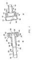
FIGs. 1 ,2 ,3 ,4 ,5 ,6 and7 include illustrations of an exemplary connector. -
FIGs. 8, 9, and 10 include illustrations of an exemplary interlocking mechanism. -
FIG. 11 includes an illustration of an exemplary assembly including an exemplary connector. -
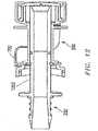
FIG. 12 includes an illustration of an exemplary connector. - The use of the same reference symbols in different drawings indicates similar or identical items.
- In an exemplary embodiment, a connector includes mating connectors that can be coupled together and to various fluid conduit systems to provide a fluid path between the fluid systems. The connector assembly provides a sterile environment for fluid to flow between containers or conduits and prevents contaminants from entering the fluid path.
- In an embodiment illustrated in
FIGs. 1 ,2 ,3 ,4 , and5 the connector assembly includes twoconnectors housing 100 that defines aseal structure 130 and acoupling 420. Thesecond connector 20 includes ahousing 200 surrounding astem 230. In an example, thestem 230 is configured to move axially relative to thehousing 200. Thestem 230 may include acoupling 320. When thefirst connector 10 and thesecond connector 20 are coupled, the first and second housings (100 and 200) are configured to lock together and thestem 230 is configured to engage theseal structure 130 to define a fluid passage through the coupling assembly. For directional orientation, each connector (10 and 20) and their associated housings (100 and 200) have a proximal end illustrated nearest the opposing connector and a distal end illustrated furthest from the opposing connector. The proximal ends of thefirst housing 100 andsecond housing 200 are dimensioned to matingly engage. In an embodiment, thefirst housing 100 has an inside diameter and thesecond housing 200 has an outside diameter wherein the inside diameter of thefirst housing 100 is greater than the outside diameter of thesecond housing 200 to provide a frictional fit. In an alternative embodiment, thefirst housing 100 has an outside diameter and thesecond housing 200 has an inside diameter wherein the inside diameter of thesecond housing 200 is greater than the outside diameter of thefirst housing 100 to provide a frictional fit. - In an embodiment, the
first housing 100 and thesecond housing 200 may include an interlocking mechanism adapted to interlock thefirst housing 100 in a predetermined relationship with thesecond housing 200. In an example, the interlocking mechanism may have any suitable configuration to prevent the axial movement offirst housing 100 andsecond housing 200 when they are matingly engaged. The interlocking mechanism may also be configured to prevent rotational movement offirst housing 100 andsecond housing 200 when they are matingly engaged. Exemplary interlocking mechanisms include threaded connections or tab and groove connections. In an example, as illustrated inFIG. 1 , thefirst housing 100 includes an inner sidewall with agroove 110 along at least a portion of the circumference of the sidewall. One ormore grooves 110 may extend along the inner sidewall. The opposingsecond housing 200 includes an outer diameter. The outer diameter of thesecond housing 200 includes one ormore tabs 210 that extend beyond the periphery of the outside diameter. Hence, when thesecond housing 200 andfirst housing 100 are matingly engaged, thetabs 210 of thesecond housing 200 engage thegrooves 110 of thefirst housing 100 to interlock thehousings tabs 210 are configured to bend with the frictional force of the sidewall offirst housing 100 andgrooves 110. In an exemplary embodiment, thegrooves 110 are configured such thatfirst housing 100 andsecond housing 200 are rotated to engage thetabs 210 with thegrooves 110 and lock thehousings groove 110 may be configured in an "L" shape to first proximally and axially guide thetab 210 and next rotationally guide the tab withfirst housing 100. In an embodiment, the interlocking device is arranged to irreversibly lock when engaged, i.e., the unlocking would result in damage to the housing (100 or 200). - In an embodiment, the
first housing 100 includes avalve support system 140 that defines afirst aperture 120 or internal chamber with an open proximal end. Further, thesecond housing 200 includes avalve support system 240 that defines asecond aperture 220 or internal chamber with an open proximal end. Typically, thefirst aperture 120 and thesecond aperture 220 are configured to align, such as aligning in a concentric fashion along an axis, when thefirst housing 100 is coupled to thesecond housing 200. As illustrated, thevalve support systems housings valve support systems housings - In an embodiment, the
stem 230 and theseal structure 130 matingly engage with a frictional fit. Alternatively, theconnector 10 may include an axially movable stem and theconnector 20 may include a seal structure. In a further example, bothconnectors stem 230 andseal structure 130, when engaged, define a generally hollow body having an interior surface, defining a lumen for fluid flow therethrough to connect the distal ends ofconnectors couplings - In an exemplary embodiment, a
valve 150 seals the open proximal end of thefirst aperture 120 defined by thefirst housing 100. Thevalve 150 is affixed to prevent inadvertent displacement of thevalve 150 and exposure of thefirst aperture 120 to the ambient environment. For example, thevalve 150 may be attached to avalve support system 140 defining thefirst aperture 120 through any suitable technique to physically or chemically attach thevalve 150. In an exemplary embodiment, thevalve 150 is permanently affixed to thevalve support system 140. In an embodiment, thevalve 150 is permanent affixed with avalve retainer 102. Thevalve retainer 102 may be dimensioned between thevalve 150 and the inside diameter of thehousing 100 in any suitable configuration to permanently affix thevalve 150 to thevalve support system 140. For instance, thevalve retainer 102 may be dimensioned to frictionally fit thevalve 150 to thevalve support system 140. - In addition, a
valve 250 may seal the open proximal end of thesecond aperture 220 in thesecond housing 200. Thevalve 250 may be affixed to prevent inadvertent displacement of thevalve 250 and exposure of thesecond aperture 220 to the ambient environment. Thevalve 250 may be attached to avalve support system 240 defining thesecond aperture 220 through any suitable technique to physically or chemically attachvalve 250. Thevalve 250 may be permanently affixed to thevalve support system 240. In an embodiment, thevalve 250 is permanent affixed with avalve retainer 202. Thevalve retainer 202 may be dimensioned between thevalve 250 and the inside diameter of thehousing 200 in any suitable configuration to permanently affix thevalve 250 to thevalve support system 240. For instance, thevalve retainer 202 may be dimensioned to frictionally fit thevalve 250 to thevalve support system 240. - In an embodiment, the
valve 150 is configured to align withvalve 250. For example, thehousings first housing 100 and thesecond housing 200 matingly engage,valve 150 aligns with andcontacts valve 250, as illustrated inFIG. 2 . In an exemplary embodiment,valve 150 engages or may adhere tovalve 250. Thevalves second aperture 220 and thefirst aperture 120, respectively to facilitate face-to-face engagement of thevalves - In an embodiment, the
stem 230 is movably housed in thesecond housing 200. For example, thestem 230 is dimensioned to move axially within thesecond housing 200 and proximally to engage theseal structure 130 infirst housing 100. In an example, the distal end of thestem 230 includes aflange 270 on the outside diameter of thestem 230. Typically, once thevalves stem 230 is engaged to move axially and proximally through thevalve 250 and thevalve 150 to fold both valves in the direction of the movement of thestem 230 and to the outside diameter of thestem 230 until thestem 230 engages theseal structure 130. In an exemplary embodiment, thestem 230 engagesseal 160 on the proximal end of theseal structure 130 to provide a tight frictional fit. - In a further embodiment, the
stem 230 may include a locking mechanism. The locking mechanism may be of a configuration that restricts the axial retreat of thestem 230 within thesecond housing 200. Thesecond housing 200 is typically dimensioned to allow axial advancement of thestem 230 and maintain a tight frictional fit withseal structure 130. In an exemplary embodiment, onceseal 160 is engaged withstem 230, the locking mechanism may prevent axial movement of thestem 230 in the distal direction relative to thesecond housing 200. For example, alocking tab 290 may be located on the inside diameter of the distal end of thehousing 200. In an example, thelocking tab 290 may be a radially projecting fin. Further, one ormore grooves stem 230 and may be configured to engage thelocking tab 290. Thefirst groove 280 may be configured along the central axis ofstem 230 to prevent movement of thestem 230 in the distal direction relative to thehousing 200 and accidental exposure of theaperture 220 to the environment prior to engagingfirst housing 100. Oncefirst housing 100 andsecond housing 200 are engaged, theflange 270 is moved proximally untilsecond groove 300 is engaged withlocking tab 290. Thesecond groove 300 may be configured along the distal axis ofstem 230 to prevent further axial movement oncestem 230 is engaged withseal 160, such as to prevent thestem 230 from disengaging theseal 160. In an embodiment, the locking mechanism irreversibly locks when engaged. - The
stem 230 may include an interlocking mechanism that is configured to pass through thehousing 200 to engagestem 230. As illustrated in the embodiments ofFIGs. 6 ,7 ,8, 9, and 10 the interlocking mechanism includes aclip 700.Clip 700 may be shaped in a horseshoe configuration with a forkedend 810 and aclosed end 820. Theclosed end 820 is typically configured for the user to engage the interlocking mechanism and may be dimensioned with a flat face. In an embodiment, the interior of forkedend 810 includeselongated tabs 830. The forkedend 810 may further include hooks 840.Elongated tabs 830 can engage thefirst groove 280 located on the outside diameter of thestem 230. Once thefirst housing 100 and thesecond housing 200 are engaged, theclosed end 820 is pushed toward thehousing 200 to disengage theelongated tabs 830 from thefirst groove 280. Thehooks 840 may be dimensioned to engage the outside diameter of thehousing 200 to lock theclip 700 in an open position. Theclip 700 is dimensioned to allow proximal movement of thestem 230 once thehooks 840 engage the outside diameter of thehousing 200. In an embodiment, the locking mechanism irreversibly locks when engaged. - In a further example, the
stem 230 may include a set ofadjacent ridges 1202, as illustrated inFIG. 12 . For example, theadjacent ridges 1202 may be concentric ridges to engage thehousing 200 or theclip 700. In particular, theadjacent ridges 1202 and thehousing 200 or theclip 700 engage to permit thestem 230 to ratchet forward, preventing backward or reverse movement of thestem 230. - In a further embodiment, one or
more locking tabs 720 may be configured along the outside diameter of theflange 270. The distal end of thehousing 200 may be configured to engage theflange 270 and thelocking tab 720. For instance, the inside diameter of the distal end of thehousing 200 may be greater than the outside diameter of theflange 270 to enable theflange 270 to matingly engage the distal end of thehousing 200. Further, the distal end of thehousing 200 may includecomplimentary grooves 710 to matingly engage thetabs 720 of theflange 270 to interlock theflange 270 and thehousing 200. For example, thetabs 720 are configured to bend with the frictional force of the sidewall of thesecond housing 200 and thegrooves 710. In an exemplary embodiment, thegrooves 710 are configured such that theflange 270 and thesecond housing 200 are rotated to engage thetabs 720 with thegrooves 710 and lock theflange 270 and thehousing 200. For example, thegroove 710 may be configured in an "L" shape to first proximally and axially guide thetab 720 and next rotationally guide the tab with thesecond housing 200. Thegroove 710 and thetab 720 may be configured to prevent further axial movement once thestem 230 is engaged with theseal 160, such as to prevent thestem 230 from disengaging theseal 160. In an embodiment, the locking mechanism irreversibly locks when engaged. - To provide a conduit for fluid flow, the
stem 230 and theseal structure 130 may slidingly engage after pushing open thevalves valves first housing 100 along the outside diameter of thesecond stem 230, for example, in the direction of the movement of thestem 230. Thevalves apertures valves - The integrity of the sterile environment may be maintained through the
stem 230 contacting theseal structure 130, while not being exposed to the environment beyond the sealedapertures stem 230 is configured to move through thevalves valves connector 10 includes theseal structure 130 and aseal 160 around the proximal end of theseal structure 130. Theseal structure 130 is configured to engage the proximal end ofstem 230 after the first andsecond housings stem 230 is dimensioned to form a tight frictional fit between theseal structure 130 and thestem 230 when thestem 230 is matingly engaged withseal structure 130 and engagesseal 160. In an example, theseal 160 may be continuous and may completely engage the proximal end of thestem 230. For example, theseal 160 may be an O-ring. - In an embodiment, the
stem 230 is surrounded by thehousing 200. Thestem 230 is dimensioned to form a tight frictional fit between the outside diameter and distal end of thestem 230 and the distal end of thehousing 200. In addition, aseal 260 is located between thehousing 200 and thestem 230. For example, theseal 260 may continuously surround the circumference of thestem 230. In an example, theseal 260 may be disposed in a groove in the outside diameter of thestem 230. Alternatively, theseal 260 may be disposed in a groove along an inside surface of the distal end of thehousing 200. In an example, theseal 260 may be an O-ring. In a particular embodiment, theseal 260 forms a seal with thestem 230 and the interior, distal end ofhousing 200 to seal thesecond aperture 220 from the ambient environment and allow thestem 230 to move axially. - Typically, the
valves seals valves seals valves seals valves seals - In an embodiment, the proximal end of the
housings valves FIG. 5 . Typically, thecaps housings FIG. 5 , thecaps cover ribs 135 and 235. Typically, the proximal ends of thehousings housings annular groove caps housings ribs 135 and 235 engage theannular grooves caps caps housings housings caps valves caps tab 125 and 225 attached to thecovers caps - In an embodiment, the
housing housing housing housing FIG. 6 , thehousing 100 may contain a plurality ofridges 610 along at least a portion of the outside surface of thehousing 100. Thehousing 100 may also contain aflange 630. In another exemplary embodiment, thehousing 200 includes a plurality ofwings 620 along the outside surface of the stem portion of thehousing 200. - The connector assembly may be made of any material that is compatible with the nature of the particular fluid or sterilization technique utilized. In an embodiment, at least a portion of the connector assembly, such as the
housings caps - In an exemplary embodiment, the
stem 230 has an interior surface and an exterior surface. Further, thehousing 100 defining theseal structure 130 may also have an interior and an exterior surface. The interior surface, for example, defines a lumen for fluid flow therethrough. In general, the interior surface has an initial roughness (Ra) not greater than 50 microns, such as not greater than about 10 microns, or even, not greater than about 1 micron. An exemplary polymer for use in the stems, seals, and other components includes a polyolefin. In an example, the polyolefin includes polyethylene or polypropylene. In particular, the polyolefin may include halogenated polyolefin. For example, the halogenated polyolefin may include polyvinyl chloride (PVC), polyvinyl fluoride (PVF), polyvinylidene fluoride (PVDF), polyvinylidene chloride (PVDC), polycholorotrifluoroethylene (PCTFE), polytetrafluoroethylene (PTFE), or blends or copolymers thereof. In a particular embodiment, theliner - The distal end of each
housing stem 230 thehousing 100 opposite theseal structure 130 may include at least oneannular rib stem 230 and thehousing 100 may further include a tapered outside diameter to definecouplings stem 230 and of thehousing 100. Alternatively, thestem 230 and thehousing 100 may be configured with couplings of other types, such as those coupling configurations known in the industry. In an embodiment, the distal end of thefirst housing 100 and thestem 230 are configured with an outside diameter of about ¼ inch, about 3/8 inch, and about ½ inch. - Each connector may be attached to or may be formed as part of any suitable fluid container or conduit, for example, a section of tubing, an inlet or outlet of a housing, such as a filter housing or drip chamber housing, or a flexible bag such as a blood bag.
FIG. 11 includes an illustration of an exemplary fluid system in which acontainer 500 is fluidically coupled to acontainer 650 through a tubing 510 coupled to afirst connector 520 that is coupled to asecond connector 530, which is coupled to atubing 540 that is coupled to thecontainer 650. In particular, the connector may be suitable for fluid communication where the pressure rating is greater than or equal to about 50 psi or 3.5 bar. - In an exemplary embodiment, the connector assembly is suitable for sterilization. In an embodiment, the connector may be sterilized by radiation sterilization or heat sterilization. In particular, the materials of the connector may be selected based on the anticipated method of sterilization. Particularly, the connector assembly may be configured for sterilization in an autoclave at temperatures of about 134°C at 17 psi for about 1 hour. Alternatively, the connector assembly may be configured for sterilization by radiation using gamma rays at 25 kGy for 2 doses. Further, the connector assembly may be packaged to maintain sterilization.
- In an exemplary embodiment, operation of the connectors includes removing the
caps first housing 100 and thesecond housing 200, respectively. The operator then matingly engages thefirst housing 100 and thesecond housing 200, as illustrated inFIG. 2 . The interlockingtab 210 of thesecond housing 200 engages thegroove 110 of thefirst housing 100 axially and proximally and thehousings housings valves flange 270 to axially and proximally move thestem 230. Thestem 230 may open the path for fluid to flow through by pushing open thevalves stem 230 and to the outside diameter of thestem 230, as illustrated inFIG. 3 . Theflange 270 is pushed until it engages theseal 160 of theseal structure 130, thestem 230 is locked into position by thetab 290 and thesecond groove 300, and thestem 230 is sealed with theseal 260, as illustrated inFIG. 4 . The sanitary and sterile connection is complete. - In another exemplary embodiment, operation of the operation of the connectors includes removing the
caps first housing 100 and thesecond housing 200, respectively. The operator then matingly engages thefirst housing 100 and thesecond housing 200. The interlockingtab 210 of thesecond housing 200 engages thegroove 110 of thefirst housing 100 axially and proximally and thehousings housings valves FIGs. 9 and 10 , an operator may push theclip 700 to unlock thestem 230 from thegroove 280. The operator may push theflange 270 to axially and proximally move thestem 230. Thestem 230 may open the path for fluid to flow through by pushingopen valves stem 230 and to the outside diameter of thestem 230. Theflange 270 is pushed until thestem 230 engages theseal 160 of theseal structure 130. TheStem 230 is locked into position by rotating and permanently locking thetab 720 and thegroove 710, and thestem 230 is sealed withseal 260. The sanitary and sterile connection is complete. - In particular, the connector assembly and method of connecting the assembly may provide advantages over other sterile connectors. For example, the integrity of the sterile environment may be maintained through the
stem 230 contacting theseal structure 130 while not being exposed to the environment beyond the sealedapertures stem 230 is configured to move through thevalves valves - According to an embodiment, a connector is provided. The connector comprises a stem defining a fluid passage therethrough, wherein the stem is configured to matingly engage a complimentary structure located on a complimentary connector, a housing surrounding the stem and defining an aperture, wherein the housing is configured to engage a complimentary housing of the complimentary connector, and a valve disposed over the aperture, wherein the valve is configured to align with a complimentary valve when the housing engages the complimentary housing. The stem may be configured to move in relation to the housing and through the valve and complimentary valve to engage the complimentary structure after the housing engages the complimentary housing. The valve may be configured to fold with the complimentary valve in a direction of movement of the stem when the stem moves through the valve and the complimentary valve. The valve may adhere to the complimentary valve. The valve may comprise a silicone elastomer, an ethylene propylene diene monomer (EPDM), a thermoplastic elastomer (TPE), or a thermoplastic vulcanizate (TPV). The housing may further include a proximal end and a cap disposed thereon. The stem further may include an interior surface wherein the interior surface defines the fluid passage. The interior surface may comprise a halogenated polyolefin. The housing may include an interlocking mechanism configured to matingly engage the complimentary housing. The housing may include at least one tab, and the stem may include at least one groove, wherein the at least one tab and the at least one groove may be configured to matingly engage. The connector may further comprise at least one seal disposed between the stem and the housing. The at least one seal may include an O-ring. At least a portion of the housing may comprise polyvinylidene fluoride or polypropylene. The stem may further include a flange. The flange may be configured to abut the housing when the stem engages the complimentary structure.
- According to another embodiment, a connector is provided. The connector comprises a first housing defining an aperture configured to engage a complimentary second housing of a complimentary connector, a first valve disposed over the aperture, wherein the first valve is configured to align with a complimentary second valve when the first housing engages the second housing, and a seal structure configured to engage a stem of the complimentary connector after the first and second housings engage. The stem of the complimentary connector may be configured to move through the first and second valves to engage the seal structure. The first valve may be configured to fold with the second valve in a direction of the movement of the stem when the stem moves through the first and second valves. The seal structure may include an O-ring.
- According to another embodiment, a sterile connector assembly for mounting on a fluid system is provided. The sterile connector assembly comprises a first connector. The first connector includes a stem defining a fluid passage therethrough, a first housing surrounding the stem and defining a first aperture, and a first valve disposed over the first aperture. The sterile connector assembly further comprises a second connector. The second connector includes a second housing configured to matingly engage the first housing, the second housing defining a second aperture and defining a seal structure, wherein the seal structure is configured to engage the stem, and a second valve disposed over the second aperture, wherein the second valve is configured to engage the first valve when the first housing engages the second housing. The sterile connector assembly may have a pressure rating of at least about 50 psi.
- According to a further embodiment, a fluid system is provided. The fluid system comprises a first fluid container. The first fluid container is coupled to a distal end of a first housing of a first connector. The proximal end of the first housing defines a first aperture. A first valve is disposed over the first aperture. The proximal end further defines a seal structure. The fluid system further comprises a second fluid container. The second fluid container is coupled to a stem of a second connector. The second connector includes the stem and a second housing. A proximal end of the second housing is configured to matingly engage the first housing. The stem defines a fluid passage therethrough. The second housing surrounds the stem and defines a second aperture. A second valve is disposed over the second aperture. The second valve is configured to align with the first valve when the first housing engages the second housing. The stem is configured to engage the seal structure of the first housing after the first and second housings engage. The distal end of the first housing and a distal end of the second housing may have an outside diameter of about ¼ inch, about 3/8 inch, or about ½ inch.
- Note that not all of the activities described above in the general description or the examples are required, that a portion of a specific activity may not be required, and that one or more further activities may be performed in addition to those described. Still further, the order in which activities are listed are not necessarily the order in which they are performed.
- In the foregoing specification, the concepts have been described with reference to specific embodiments. However, one of ordinary skill in the art appreciates that various modifications and changes can be made without departing from the scope of the invention as set forth in the claims below.
- Accordingly, the specification and figures are to be regarded in an illustrative rather than a restrictive sense, and all such modifications are intended to be included within the scope of invention.
- As used herein, the terms "comprises," "comprising," "includes," "including," "has," "having" or any other variation thereof, are intended to cover a non-exclusive inclusion. For example, a process, method, article, or apparatus that comprises a list of features is not necessarily limited only to those features but may include other features not expressly listed or inherent to such process, method, article, or apparatus. Further, unless expressly stated to the contrary, "or" refers to an inclusive-or and not to an exclusive-or. For example, a condition A or B is satisfied by any one of the following: A is true (or present) and B is false (or not present), A is false (or not present) and B is true (or present), and both A and B are true (or present).
- Also, the use of "a" or "an" are employed to describe elements and components described herein. This is done merely for convenience and to give a general sense of the scope of the invention. This description should be read to include one or at least one and the singular also includes the plural unless it is obvious that it is meant otherwise.
- Benefits, other advantages, and solutions to problems have been described above with regard to specific embodiments. However, the benefits, advantages, solutions to problems, and any feature(s) that may cause any benefit, advantage, or solution to occur or become more pronounced are not to be construed as a critical, required, or essential feature of any or all the claims.
- After reading the specification, skilled artisans will appreciated that certain features are, for clarity, described herein in the context of separate embodiments, may also be provided in combination in a single embodiment. Conversely, various features that are, for brevity, described in the context of a single embodiment, may also be provided separately or in any subcombination. Further, references to values stated in ranges include each and every value within that range.
Claims (15)
- A method of coupling a connector (20) and a complimentary connector (10), wherein the connector comprises a stem (230) defining a fluid passage therethrough, wherein the stem is configured to matingly engage a complimentary structure (130) located on the complimentary connector;
a housing (200) surrounding the stem and defining an aperture (220), wherein the housing is configured to engage a complimentary housing (100) of the complimentary connector; and
a valve (250) disposed over the aperture, wherein the valve is configured to align with a complimentary valve (150) when the housing engages the complimentary housing;
the method comprising:
engaging the housing and the complimentary housing; and
moving the stem in relation to the housing to push open the valve and complimentary valve and to move through the valve and the complimentary valve to matingly engage the complimentary structure after the housing engages the complimentary housing, wherein the valve folds with the complimentary valve in the direction of movement of the stem when the stem moves through the valve and the complimentary valve. - The method of claim 1, wherein the valve contacts the complimentary valve.
- The method of claim 1, wherein moving the stem pushes open the valves without contacting an outside surface of the valves to provide a sterile environment.
- The method of claim 1, wherein moving the stem in relation to the housing matingly engages the stem with the complimentary structure.
- The method of claim 4, wherein the mating engagement of the stem with the complimentary structure provides a tight frictional fit.
- The method of claim 4, wherein the complimentary structure comprises a seal structure.
- The method of claim 6, wherein the seal structure comprises an O-ring.
- The method of claim 1, wherein matingly engaging the connector and the complimentary connector further comprises rotating and locking the housings (100, 200).
- The method of claim 8, wherein locking the housings comprises engaging an interlock tab (210) of the housing (200) with a groove (110) of the complimentary housing (100).
- The method of claim 1, further comprising locking the stem within the housing to prevent axial movement of the stem.
- The method of claim 10, wherein locking the stem includes engaging a locking tab (290) with a groove (280, 300).
- The method of claim 1, wherein fluid flows within an interior surface of the stem.
- The method of claim 1, wherein the connector is attached to or formed as part of a fluid container, a fluid conduit, a section of tubing, an inlet of a housing, an outlet of a housing, or a flexible bag.
- The method of claim 1, wherein the complimentary connector is attached to or formed as part of a fluid container, a fluid conduit, a section of tubing, an inlet of a housing, an outlet of a housing, or a flexible bag.
- The method of claim 1, wherein the fluid connection has a pressure rating of at least about 50 psi.
Applications Claiming Priority (3)
| Application Number | Priority Date | Filing Date | Title |
|---|---|---|---|
| US88775107P | 2007-02-01 | 2007-02-01 | |
| PCT/US2008/001426 WO2008094707A1 (en) | 2007-02-01 | 2008-02-01 | Connector assembly |
| EP08725115.3A EP2121114B1 (en) | 2007-02-01 | 2008-02-01 | Connector assembly |
Related Parent Applications (2)
| Application Number | Title | Priority Date | Filing Date |
|---|---|---|---|
| EP08725115.3A Division-Into EP2121114B1 (en) | 2007-02-01 | 2008-02-01 | Connector assembly |
| EP08725115.3A Division EP2121114B1 (en) | 2007-02-01 | 2008-02-01 | Connector assembly |
Publications (2)
| Publication Number | Publication Date |
|---|---|
| EP3530313A1 true EP3530313A1 (en) | 2019-08-28 |
| EP3530313B1 EP3530313B1 (en) | 2022-08-31 |
Family
ID=39422519
Family Applications (2)
| Application Number | Title | Priority Date | Filing Date |
|---|---|---|---|
| EP08725115.3A Active EP2121114B1 (en) | 2007-02-01 | 2008-02-01 | Connector assembly |
| EP19167859.8A Active EP3530313B1 (en) | 2007-02-01 | 2008-02-01 | Connector assembly |
Family Applications Before (1)
| Application Number | Title | Priority Date | Filing Date |
|---|---|---|---|
| EP08725115.3A Active EP2121114B1 (en) | 2007-02-01 | 2008-02-01 | Connector assembly |
Country Status (6)
| Country | Link |
|---|---|
| US (1) | US8899267B2 (en) |
| EP (2) | EP2121114B1 (en) |
| JP (2) | JP2010518330A (en) |
| CN (1) | CN101626803B (en) |
| BR (1) | BRPI0806935B1 (en) |
| WO (1) | WO2008094707A1 (en) |
Cited By (9)
| Publication number | Priority date | Publication date | Assignee | Title |
|---|---|---|---|---|
| US12072049B2 (en) | 2020-06-26 | 2024-08-27 | Carefusion 303, Inc. | Connector coupling assembly |
| US12109387B2 (en) | 2022-11-11 | 2024-10-08 | Carefusion 303, Inc. | Connector coupling assembly |
| US12186518B2 (en) | 2023-04-25 | 2025-01-07 | Carefusion 303, Inc. | Fluid connector system |
| US12208231B2 (en) | 2021-06-30 | 2025-01-28 | Carefusion 303, Inc. | Fluid connector system |
| US12208230B2 (en) | 2022-11-09 | 2025-01-28 | Carefusion 303, Inc. | Fluid connector assembly that seals flow paths when the connectors are disconnected |
| US12403295B2 (en) | 2022-08-11 | 2025-09-02 | Carefusion 303, Inc. | Fluid connector system |
| US12420074B2 (en) | 2023-07-13 | 2025-09-23 | Carefusion 303, Inc. | Fluid connector assembly |
| US12502518B2 (en) | 2022-04-07 | 2025-12-23 | Carefusion 303, Inc. | Fluid connector system |
| US12584578B2 (en) | 2023-03-27 | 2026-03-24 | Carefusion 303, Inc. | Torsional connector coupling assembly |
Families Citing this family (63)
| Publication number | Priority date | Publication date | Assignee | Title |
|---|---|---|---|---|
| HK1077154A2 (en) | 2003-12-30 | 2006-02-03 | Icu Medical, Inc. | Valve assembly |
| US7998134B2 (en) | 2007-05-16 | 2011-08-16 | Icu Medical, Inc. | Medical connector |
| US20070088292A1 (en) | 2005-07-06 | 2007-04-19 | Fangrow Thomas F Jr | Medical connector with closeable male luer |
| AU2009214439B2 (en) * | 2008-02-14 | 2014-09-25 | Solventum Intellectual Properties Company | Devices and methods for treatment of damaged tissue |
| GB2460227A (en) * | 2008-05-19 | 2009-11-25 | Walker & Co James Ltd | Valve diaphragm |
| US9168366B2 (en) | 2008-12-19 | 2015-10-27 | Icu Medical, Inc. | Medical connector with closeable luer connector |
| JP5271174B2 (en) * | 2009-06-29 | 2013-08-21 | 日本コヴィディエン株式会社 | Connection structure between fistula catheter and fluid supply tube |
| JP6282112B2 (en) | 2010-04-05 | 2018-02-21 | ダニエル ピーワイ | Sterile connector and method with a pending bendable ring |
| US8668229B2 (en) * | 2010-11-30 | 2014-03-11 | Baker Hughes Incorporated | Contamination resistant connecting system and method |
| US9814872B2 (en) | 2011-04-28 | 2017-11-14 | Sanofi-Aventis Deutschland Gmbh | Valve arrangement for medical device |
| JP5930481B2 (en) * | 2011-06-30 | 2016-06-08 | テルモ株式会社 | Connector assembly and male connector |
| AU2012304344B2 (en) | 2011-09-09 | 2016-02-04 | Icu Medical, Inc. | Medical connectors with fluid-resistant mating interfaces |
| US8535241B2 (en) | 2011-10-13 | 2013-09-17 | Magnolia Medical Technologies, Inc. | Fluid diversion mechanism for bodily-fluid sampling |
| US8864684B2 (en) | 2011-10-13 | 2014-10-21 | Magnolia Medical Technologies, Inc. | Fluid diversion mechanism for bodily-fluid sampling |
| CN103091504A (en) * | 2011-10-31 | 2013-05-08 | 深圳迈瑞生物医疗电子股份有限公司 | Pipeline adapter assembly, reagent container assembly and sample analyzer |
| US9022950B2 (en) | 2012-05-30 | 2015-05-05 | Magnolia Medical Technologies, Inc. | Fluid diversion mechanism for bodily-fluid sampling |
| US9060724B2 (en) | 2012-05-30 | 2015-06-23 | Magnolia Medical Technologies, Inc. | Fluid diversion mechanism for bodily-fluid sampling |
| WO2014022275A1 (en) | 2012-08-01 | 2014-02-06 | Magnolia Medical Technologies, Inc. | Fluid diversion mechanism for bodily-fluid sampling |
| US20150217104A1 (en) * | 2012-08-28 | 2015-08-06 | Fresenius Kabi Deutschland Gmbh | Connector for producing a fluid connection to a second connector, connector system, and method for producing a fluid connection |
| WO2014058945A1 (en) | 2012-10-11 | 2014-04-17 | Bullington Gregory J | Systems and methods for delivering a fluid to a patient with reduced contamination |
| CN109171766A (en) | 2012-11-30 | 2019-01-11 | 木兰医药技术股份有限公司 | Body fluid barrier means and the method for completely cutting off body fluid using body fluid barrier means |
| US10772548B2 (en) | 2012-12-04 | 2020-09-15 | Magnolia Medical Technologies, Inc. | Sterile bodily-fluid collection device and methods |
| IL303591B2 (en) | 2012-12-04 | 2025-11-01 | Magnolia Medical Technologies Inc | Sterile device and methods for collecting body fluids |
| GB2509501B (en) * | 2013-01-03 | 2018-05-09 | Intersurgical Ag | Improvements in relation to valves |
| CN105682732B (en) * | 2013-11-07 | 2019-06-07 | 通用电气健康护理生物科学股份公司 | Connector for sterile connection |
| DE202014100585U1 (en) | 2014-02-11 | 2014-04-22 | Heinz Meise Gmbh | Device for the sterile connection of medical disposable articles |
| EP4218708B1 (en) | 2014-03-03 | 2024-12-18 | Magnolia Medical Technologies, Inc. | Apparatus for disinfection of a specimen container |
| US9186493B2 (en) * | 2014-04-15 | 2015-11-17 | Advanced Scientific, Inc. | Aseptic connector |
| US9907945B2 (en) | 2014-05-01 | 2018-03-06 | Michael D. Laufer | Medical devices and methods for fluid transfer |
| EP3034062B1 (en) * | 2014-12-19 | 2017-03-22 | Fresenius Kabi Deutschland GmbH | Connector system comprising at least two outlet ports |
| EP3875824B1 (en) | 2015-04-20 | 2024-10-30 | Colder Products Company | Single-use aseptic fluid couplings |
| EP3733067B1 (en) * | 2015-09-03 | 2023-06-14 | Magnolia Medical Technologies, Inc. | System for maintaining sterility of a specimen container |
| CN108290034B (en) * | 2015-10-08 | 2021-03-05 | 考尔得产品公司 | Reusable sterile fluid coupling |
| JP2019502483A (en) | 2016-01-19 | 2019-01-31 | ダニエル ピーワイ | Disposable connector |
| EP3293524B1 (en) * | 2016-09-12 | 2021-06-09 | Stratec SE | Fluidic coupling |
| JP6819900B2 (en) * | 2016-09-28 | 2021-01-27 | 株式会社ジェイ・エム・エス | Female connector |
| US10485483B1 (en) * | 2016-10-17 | 2019-11-26 | Srs Medical Systems, Llc | Diagnostic drainage catheter assembly and methods |
| US12097027B2 (en) | 2016-11-18 | 2024-09-24 | Magnolia Medical Technologies, Inc. | Systems and methods for sample collection with reduced hemolysis |
| JP7273807B2 (en) | 2017-06-09 | 2023-05-15 | マグノリア メディカル テクノロジーズ,インコーポレイテッド | Fluid control device and method of using same |
| EP3681384B1 (en) | 2017-09-12 | 2022-12-28 | Magnolia Medical Technologies, Inc. | A system |
| US11419531B2 (en) | 2017-12-07 | 2022-08-23 | Magnolia Medical Technologies, Inc. | Fluid control devices and methods of using the same |
| US11590333B2 (en) | 2018-01-22 | 2023-02-28 | Saint-Gobain Performance Plastics Corporation | Tubular coupling |
| US10914412B2 (en) | 2018-06-28 | 2021-02-09 | Watts Regulator Co. | Backflow prevention assembly having a variable lay-length and orientation |
| EP3897812A4 (en) * | 2018-12-20 | 2022-11-16 | Centre for Commercialization of Regenerative Medicine | Systems and methods for a reusable, aseptic connector |
| CN109675187A (en) * | 2018-12-29 | 2019-04-26 | 广东百合医疗科技股份有限公司 | A kind of glue valve and anti-glutinous medical infusion connector certainly |
| WO2020163744A1 (en) | 2019-02-08 | 2020-08-13 | Magnolia Medical Technologies, Inc. | Devices and methods for bodily fluid collection and distribution |
| US11795666B2 (en) | 2019-05-08 | 2023-10-24 | Watts Regulator Co. | Wireless communication system within a mechanical room |
| CN114615964B (en) * | 2019-10-31 | 2025-10-28 | 纳卡特尔国际进出口股份责任有限公司 | Safe components for reconstitution, extraction, and infusion of medications |
| US12195954B2 (en) | 2019-12-10 | 2025-01-14 | Watts Regulator Co. | System for monitoring backflow preventer condition |
| EP4084854A4 (en) | 2019-12-31 | 2023-04-19 | Colder Products Company | ASEPTIC FLUID COUPLINGS |
| GB2590977B (en) * | 2020-01-13 | 2024-02-14 | Gbuk Group Ltd | Lockable adapter assembly |
| US11480281B2 (en) | 2020-06-11 | 2022-10-25 | Colder Products Company | Single-use disconnect fluid couplings |
| KR20230048300A (en) | 2020-06-16 | 2023-04-11 | 생-고뱅 퍼포먼스 플라스틱스 코포레이션 | Sampling system and method of use thereof |
| US11719352B2 (en) | 2020-08-17 | 2023-08-08 | Watts Regulator Co. | Check cover assemblies for backflow prevention assemblies with integrated test cock protection shroud |
| WO2022047023A1 (en) | 2020-08-27 | 2022-03-03 | Colder Products Company | Fluid couplings |
| EP3981504A1 (en) * | 2020-10-08 | 2022-04-13 | Sartorius Stedim Biotech GmbH | Modular device for rigidly arranging and connecting individual separation units and / or functional units among each other |
| EP4678964A3 (en) * | 2021-02-08 | 2026-03-11 | Colder Products Company | Fluid coupling device and method of coupling a fluid coupling |
| WO2022265958A1 (en) | 2021-06-17 | 2022-12-22 | Colder Products Company | Aseptic fluid couplings |
| WO2023283070A1 (en) * | 2021-07-09 | 2023-01-12 | Colder Products Company | Compact fluid couplings |
| WO2023229704A1 (en) | 2022-05-23 | 2023-11-30 | Colder Products Company | Aseptic fluid couplings |
| US12023462B2 (en) * | 2022-09-29 | 2024-07-02 | Carefusion 303, Inc. | Fluid connector system |
| WO2025144732A1 (en) * | 2023-12-28 | 2025-07-03 | Luminoah, Inc. | Separable bi-directional check valve assembly |
| USD1105422S1 (en) | 2024-02-09 | 2025-12-09 | Icu Medical, Inc. | Medical connector cover |
Citations (5)
| Publication number | Priority date | Publication date | Assignee | Title |
|---|---|---|---|---|
| US4030494A (en) * | 1973-11-05 | 1977-06-21 | Francis Tenczar | Fluid connectors |
| US4256106A (en) * | 1979-04-30 | 1981-03-17 | Becton, Dickinson And Company | Resealable device |
| EP0795342A2 (en) * | 1996-03-15 | 1997-09-17 | Becton, Dickinson and Company | Disconnect for medical access devices |
| US6341802B1 (en) * | 1992-10-02 | 2002-01-29 | Pall Corporation | Fluid delivery systems and methods and assemblies for making connections |
| US20050015075A1 (en) * | 2003-07-14 | 2005-01-20 | B & D Research And Development Inc. | Coupling device for medical lines |
Family Cites Families (73)
| Publication number | Priority date | Publication date | Assignee | Title |
|---|---|---|---|---|
| US400748A (en) * | 1889-04-02 | Cables | ||
| US3837687A (en) | 1972-12-29 | 1974-09-24 | G Leonard | Coupling for tubing |
| US3865411A (en) * | 1973-03-29 | 1975-02-11 | Union Carbide Corp | Sterile connector for conduits |
| US4022205A (en) | 1973-11-05 | 1977-05-10 | Tenczar Francis J | Fluid connectors |
| FR2261085A1 (en) * | 1974-02-14 | 1975-09-12 | Mannesmann Ag | |
| US3973791A (en) | 1974-10-09 | 1976-08-10 | Hps Company, Inc. | Safety coupling device |
| US4019512A (en) * | 1975-12-04 | 1977-04-26 | Tenczar Francis J | Adhesively activated sterile connector |
| US4099748A (en) | 1976-11-12 | 1978-07-11 | Samuel Moore And Company | Hose coupling assembly |
| US4201208A (en) | 1977-11-30 | 1980-05-06 | Abbott Laboratories | Sterile connecting device |
| US4277091A (en) | 1979-04-19 | 1981-07-07 | Hunter John J | Coupling for lined pipe |
| US4334551A (en) | 1979-04-30 | 1982-06-15 | Becton Dickinson & Company | Connector |
| US4280722A (en) | 1979-08-10 | 1981-07-28 | Dayco Corporation | Hose clamp |
| US4285228A (en) | 1979-08-20 | 1981-08-25 | Anchor Coupling Co., Inc. | Crimping machine for hose assembly |
| US4330924A (en) | 1980-01-31 | 1982-05-25 | General Electric Company | Method of forming crimped tube joint |
| US4371199A (en) | 1980-01-31 | 1983-02-01 | General Electric Company | Crimped tube joint |
| WO1982001134A1 (en) | 1980-09-26 | 1982-04-15 | Corp Cordis | Sterile connector system for packaged pacer |
| US4334537A (en) | 1981-01-28 | 1982-06-15 | The Kendall Company | Drainage receptacle with anti-reflux valve |
| US4418945A (en) | 1981-06-08 | 1983-12-06 | International Business Machines Corporation | Sterile connectors |
| GB2104044B (en) | 1981-08-07 | 1985-08-21 | Craig Med Prod Ltd | Bag and valve assembley for medical use |
| US5776116A (en) | 1983-01-24 | 1998-07-07 | Icu Medical, Inc. | Medical connector |
| US4620662A (en) | 1984-07-25 | 1986-11-04 | Westinghouse Electric Corp. | Two-position sleeve brazing process |
| KR960000414B1 (en) | 1986-03-26 | 1996-01-06 | 선더홀롬 괴란 | Apparatus to be used with pipes welding together |
| US4946200A (en) | 1988-09-30 | 1990-08-07 | Colder Products Company | Self-tightening soft tubing fitting and method |
| FR2639088B1 (en) | 1988-11-17 | 1990-12-28 | Caoutchouc Manuf Plastique | COUPLING FOR FLEXIBLE PIPE WITH INTERLOCKING BY TURNING O-RING ON A LOW ANGLE CONE |
| JPH0674875B2 (en) * | 1988-12-07 | 1994-09-21 | エムス − インヴエンタ・アクチエンゲゼルシヤフト | Quick disconnect joint |
| WO1990010816A1 (en) | 1989-03-16 | 1990-09-20 | Shell Oil Company | Tubular coupling and method of forming same |
| CA1322773C (en) | 1989-07-28 | 1993-10-05 | Erich F. Klementich | Threaded tubular connection |
| GB2245670A (en) | 1990-06-27 | 1992-01-08 | Ford Motor Co | A pipe coupling |
| US5067950A (en) | 1990-07-30 | 1991-11-26 | Johnson & Johnson Medical, Inc. | Wound drainage tube/reservoir connector |
| US5122123A (en) | 1991-01-30 | 1992-06-16 | Vaillancourt Vincent L | Closed system connector assembly |
| US5259418A (en) | 1991-03-18 | 1993-11-09 | Hamrick James C | Heat reshapeable regid conduit |
| US5087086A (en) | 1991-05-13 | 1992-02-11 | General Motors Corporation | Quick connect coupling with pressure relief |
| US5131696A (en) | 1991-05-30 | 1992-07-21 | Gas Research Institute | Tube joint for annular corrugated tubing |
| JPH0579192A (en) | 1991-09-17 | 1993-03-30 | Asahi Chem Ind Co Ltd | Molding slab sorter |
| US5499439A (en) | 1992-06-02 | 1996-03-19 | Swagelok Quick-Connect Co. | Method of forming a flexible metal hose connector |
| US5404632A (en) | 1992-06-02 | 1995-04-11 | Swagelok Quick-Connect Co. | Method of forming flexible metal hose connector |
| US5511720A (en) | 1992-06-02 | 1996-04-30 | Swagelok Quick-Connect Co. | Flexible metal hose connector and method of forming same |
| JP2591101Y2 (en) | 1992-08-25 | 1999-02-24 | シーケーディ株式会社 | Pipe fittings |
| US5393101A (en) | 1992-10-02 | 1995-02-28 | Pall Corporation | Connector assembly |
| US5382059A (en) | 1994-01-13 | 1995-01-17 | Dayco Products, Inc. | Hose assembly, hose coupling and a part therefor and methods of making the same |
| US5535771A (en) | 1994-08-10 | 1996-07-16 | Becton, Dickinson And Company | Valved PRN adapter for infusion devices |
| US5492147A (en) | 1995-01-17 | 1996-02-20 | Aeroquip Corporation | Dry break coupling |
| DE19621240C2 (en) | 1996-05-25 | 1998-05-28 | Chiron Werke Gmbh | Tool holder with coolant pipe |
| WO1998004468A1 (en) | 1996-07-26 | 1998-02-05 | Peter Robert Raffaele | Container comprising longitudinally seamed body having seamless lining/liner |
| US5769558A (en) | 1996-10-17 | 1998-06-23 | Radius Metier, Inc. | Flex joint |
| US6022053A (en) | 1997-03-27 | 2000-02-08 | Flowell Corporation | Joint for coupling tubes |
| EP1716885A3 (en) | 1997-05-09 | 2006-11-15 | Pall Corporation | Connector assemblies, fluid systems, and methods for making a connection |
| US5931510A (en) | 1997-06-17 | 1999-08-03 | Teleflex Incorporated | Hose end fitting assembly |
| US6106027A (en) | 1998-04-09 | 2000-08-22 | Mulvey; Philip A. | Pull-out faucet hose |
| DE19828651C2 (en) | 1998-06-26 | 2000-07-13 | Fresenius Medical Care De Gmbh | Connector element with closure part for medical technology |
| US7358505B2 (en) | 1998-09-15 | 2008-04-15 | Baxter International Inc. | Apparatus for fabricating a reconstitution assembly |
| US6148849A (en) * | 1999-05-07 | 2000-11-21 | Dynamic Safety, Inc. | Safety vehicular fuel system |
| US6331020B1 (en) | 1999-08-23 | 2001-12-18 | Pacific Flo-Rite, Inc. | Coupling for flex pipe, rigid pipe and flexible hose |
| US6193282B1 (en) | 1999-09-24 | 2001-02-27 | Dayco Products, Inc. | Hose coupling and method of manufacture |
| US6378913B1 (en) | 1999-11-01 | 2002-04-30 | Dana Corporation | Swivel coupling and method for attaching a swivel nut to a tail piece |
| SE0001278L (en) * | 2000-04-06 | 2001-10-08 | Peter Unger Med P U Med Konsul | sterile Coupling |
| US6419278B1 (en) | 2000-05-31 | 2002-07-16 | Dana Corporation | Automotive hose coupling |
| US6394506B1 (en) | 2000-08-29 | 2002-05-28 | The Goodyear Tire & Rubber Company | Hose coupling |
| WO2002061323A1 (en) | 2001-01-31 | 2002-08-08 | Florite Industrial Co. Ltd | Hose coupling |
| US6488320B1 (en) | 2001-09-04 | 2002-12-03 | Pilot Industries, Inc. | Quick connect coupling |
| US20030127851A1 (en) | 2002-01-08 | 2003-07-10 | Guslick Gordon W. | Auto lock coupling with assymetrically-shaped gasket |
| US6874522B2 (en) * | 2002-06-18 | 2005-04-05 | Baxter International Inc. | Luer-actuated solution path connector with membrane and container using the connector and a method for establishing fluid communication with the container |
| JP2004195181A (en) | 2002-07-22 | 2004-07-15 | Fukai Kogyo Kk | Infusion circuit connecting implement, and infusion circuit connecting system |
| JP4430537B2 (en) | 2002-07-26 | 2010-03-10 | ミリポア・コーポレイション | Sterilization connector |
| JP4295997B2 (en) | 2003-01-22 | 2009-07-15 | Hoya株式会社 | Endoscope internal pressure adjustment device |
| US7014218B2 (en) | 2003-04-17 | 2006-03-21 | Parker-Hannifin | Universal fitting nipple |
| CA2536245C (en) | 2003-08-20 | 2010-09-21 | Polaris Pool Systems, Inc. | Hose clasp for a pool cleaner filter bag |
| ATE550597T1 (en) | 2003-08-26 | 2012-04-15 | Glynwed Pipe Systems Ltd | METHOD FOR JOINING A MULTI-LAYER PIPE |
| US20050082826A1 (en) * | 2003-10-17 | 2005-04-21 | Twin Bay Medical, Inc. | Barb clamp |
| WO2006004943A2 (en) | 2004-06-29 | 2006-01-12 | C. R. Bard, Inc. | Methods and systems for providing fluid communication with a gastrostomy tube |
| US7645274B2 (en) | 2004-12-10 | 2010-01-12 | Cardinal Health 303, Inc. | Self-sealing male luer connector with multiple seats |
| US7396051B2 (en) | 2005-01-14 | 2008-07-08 | Baxa Corporation | Swabable fluid connectors and fluid connector pairs |
| US8100866B2 (en) | 2005-03-24 | 2012-01-24 | B. Braun Medical Inc. | Needleless access port valves |
-
2008
- 2008-02-01 CN CN2008800037827A patent/CN101626803B/en active Active
- 2008-02-01 EP EP08725115.3A patent/EP2121114B1/en active Active
- 2008-02-01 JP JP2009548326A patent/JP2010518330A/en active Pending
- 2008-02-01 BR BRPI0806935-2A patent/BRPI0806935B1/en active IP Right Grant
- 2008-02-01 EP EP19167859.8A patent/EP3530313B1/en active Active
- 2008-02-01 WO PCT/US2008/001426 patent/WO2008094707A1/en not_active Ceased
- 2008-02-01 US US12/024,811 patent/US8899267B2/en active Active
-
2012
- 2012-10-01 JP JP2012219905A patent/JP5410589B2/en active Active
Patent Citations (5)
| Publication number | Priority date | Publication date | Assignee | Title |
|---|---|---|---|---|
| US4030494A (en) * | 1973-11-05 | 1977-06-21 | Francis Tenczar | Fluid connectors |
| US4256106A (en) * | 1979-04-30 | 1981-03-17 | Becton, Dickinson And Company | Resealable device |
| US6341802B1 (en) * | 1992-10-02 | 2002-01-29 | Pall Corporation | Fluid delivery systems and methods and assemblies for making connections |
| EP0795342A2 (en) * | 1996-03-15 | 1997-09-17 | Becton, Dickinson and Company | Disconnect for medical access devices |
| US20050015075A1 (en) * | 2003-07-14 | 2005-01-20 | B & D Research And Development Inc. | Coupling device for medical lines |
Cited By (10)
| Publication number | Priority date | Publication date | Assignee | Title |
|---|---|---|---|---|
| US12072049B2 (en) | 2020-06-26 | 2024-08-27 | Carefusion 303, Inc. | Connector coupling assembly |
| US12208231B2 (en) | 2021-06-30 | 2025-01-28 | Carefusion 303, Inc. | Fluid connector system |
| US12502518B2 (en) | 2022-04-07 | 2025-12-23 | Carefusion 303, Inc. | Fluid connector system |
| US12403295B2 (en) | 2022-08-11 | 2025-09-02 | Carefusion 303, Inc. | Fluid connector system |
| US12208230B2 (en) | 2022-11-09 | 2025-01-28 | Carefusion 303, Inc. | Fluid connector assembly that seals flow paths when the connectors are disconnected |
| US12109387B2 (en) | 2022-11-11 | 2024-10-08 | Carefusion 303, Inc. | Connector coupling assembly |
| US12569661B2 (en) | 2022-11-11 | 2026-03-10 | Carefusion 303, Inc. | Connector coupling assembly |
| US12584578B2 (en) | 2023-03-27 | 2026-03-24 | Carefusion 303, Inc. | Torsional connector coupling assembly |
| US12186518B2 (en) | 2023-04-25 | 2025-01-07 | Carefusion 303, Inc. | Fluid connector system |
| US12420074B2 (en) | 2023-07-13 | 2025-09-23 | Carefusion 303, Inc. | Fluid connector assembly |
Also Published As
| Publication number | Publication date |
|---|---|
| US20080185056A1 (en) | 2008-08-07 |
| US8899267B2 (en) | 2014-12-02 |
| BRPI0806935A2 (en) | 2014-05-06 |
| JP2013050212A (en) | 2013-03-14 |
| EP2121114B1 (en) | 2019-05-29 |
| JP5410589B2 (en) | 2014-02-05 |
| JP2010518330A (en) | 2010-05-27 |
| EP3530313B1 (en) | 2022-08-31 |
| BRPI0806935B1 (en) | 2023-10-17 |
| CN101626803A (en) | 2010-01-13 |
| WO2008094707A1 (en) | 2008-08-07 |
| EP2121114A1 (en) | 2009-11-25 |
| CN101626803B (en) | 2013-08-21 |
Similar Documents
| Publication | Publication Date | Title |
|---|---|---|
| US8899267B2 (en) | Connector assembly | |
| EP2271398B1 (en) | Connector assembly | |
| KR101378877B1 (en) | Connector assemblies, fluid systems including connector assemblies, and procedures for making fluid connections | |
| US8585099B2 (en) | Sanitary coupling assembly | |
| US6655655B1 (en) | Connector assemblies, fluid systems, and methods for making a connection | |
| US9027968B2 (en) | Aseptic coupling devices | |
| EP2941291B1 (en) | Improvements in relation to valves | |
| CA2970669C (en) | System, apparatus and method employed with enteral systems | |
| US9851037B2 (en) | Fluid connector and method for making sealed fluid connections | |
| US12140257B2 (en) | Aseptic fluid couplings | |
| WO2011125023A1 (en) | Connection device and connection system comprising it | |
| US20160151620A1 (en) | Fluid connector with clamp and protection |
Legal Events
| Date | Code | Title | Description |
|---|---|---|---|
| PUAI | Public reference made under article 153(3) epc to a published international application that has entered the european phase |
Free format text: ORIGINAL CODE: 0009012 |
|
| STAA | Information on the status of an ep patent application or granted ep patent |
Free format text: STATUS: THE APPLICATION HAS BEEN PUBLISHED |
|
| AC | Divisional application: reference to earlier application |
Ref document number: 2121114 Country of ref document: EP Kind code of ref document: P |
|
| AK | Designated contracting states |
Kind code of ref document: A1 Designated state(s): AT BE BG CH CY CZ DE DK EE ES FI FR GB GR HR HU IE IS IT LI LT LU LV MC MT NL NO PL PT RO SE SI SK TR |
|
| STAA | Information on the status of an ep patent application or granted ep patent |
Free format text: STATUS: REQUEST FOR EXAMINATION WAS MADE |
|
| STAA | Information on the status of an ep patent application or granted ep patent |
Free format text: STATUS: EXAMINATION IS IN PROGRESS |
|
| 17P | Request for examination filed |
Effective date: 20200228 |
|
| RBV | Designated contracting states (corrected) |
Designated state(s): AT BE BG CH CY CZ DE DK EE ES FI FR GB GR HR HU IE IS IT LI LT LU LV MC MT NL NO PL PT RO SE SI SK TR |
|
| 17Q | First examination report despatched |
Effective date: 20200403 |
|
| GRAP | Despatch of communication of intention to grant a patent |
Free format text: ORIGINAL CODE: EPIDOSNIGR1 |
|
| STAA | Information on the status of an ep patent application or granted ep patent |
Free format text: STATUS: GRANT OF PATENT IS INTENDED |
|
| INTG | Intention to grant announced |
Effective date: 20220420 |
|
| GRAS | Grant fee paid |
Free format text: ORIGINAL CODE: EPIDOSNIGR3 |
|
| GRAA | (expected) grant |
Free format text: ORIGINAL CODE: 0009210 |
|
| STAA | Information on the status of an ep patent application or granted ep patent |
Free format text: STATUS: THE PATENT HAS BEEN GRANTED |
|
| AC | Divisional application: reference to earlier application |
Ref document number: 2121114 Country of ref document: EP Kind code of ref document: P |
|
| AK | Designated contracting states |
Kind code of ref document: B1 Designated state(s): AT BE BG CH CY CZ DE DK EE ES FI FR GB GR HR HU IE IS IT LI LT LU LV MC MT NL NO PL PT RO SE SI SK TR |
|
| REG | Reference to a national code |
Ref country code: CH Ref legal event code: EP Ref country code: GB Ref legal event code: FG4D |
|
| REG | Reference to a national code |
Ref country code: AT Ref legal event code: REF Ref document number: 1514854 Country of ref document: AT Kind code of ref document: T Effective date: 20220915 Ref country code: DE Ref legal event code: R096 Ref document number: 602008064599 Country of ref document: DE |
|
| REG | Reference to a national code |
Ref country code: IE Ref legal event code: FG4D |
|
| REG | Reference to a national code |
Ref country code: LT Ref legal event code: MG9D |
|
| REG | Reference to a national code |
Ref country code: NL Ref legal event code: MP Effective date: 20220831 |
|
| PG25 | Lapsed in a contracting state [announced via postgrant information from national office to epo] |
Ref country code: SE Free format text: LAPSE BECAUSE OF FAILURE TO SUBMIT A TRANSLATION OF THE DESCRIPTION OR TO PAY THE FEE WITHIN THE PRESCRIBED TIME-LIMIT Effective date: 20220831 Ref country code: NO Free format text: LAPSE BECAUSE OF FAILURE TO SUBMIT A TRANSLATION OF THE DESCRIPTION OR TO PAY THE FEE WITHIN THE PRESCRIBED TIME-LIMIT Effective date: 20221130 Ref country code: LV Free format text: LAPSE BECAUSE OF FAILURE TO SUBMIT A TRANSLATION OF THE DESCRIPTION OR TO PAY THE FEE WITHIN THE PRESCRIBED TIME-LIMIT Effective date: 20220831 Ref country code: LT Free format text: LAPSE BECAUSE OF FAILURE TO SUBMIT A TRANSLATION OF THE DESCRIPTION OR TO PAY THE FEE WITHIN THE PRESCRIBED TIME-LIMIT Effective date: 20220831 Ref country code: FI Free format text: LAPSE BECAUSE OF FAILURE TO SUBMIT A TRANSLATION OF THE DESCRIPTION OR TO PAY THE FEE WITHIN THE PRESCRIBED TIME-LIMIT Effective date: 20220831 |
|
| REG | Reference to a national code |
Ref country code: AT Ref legal event code: MK05 Ref document number: 1514854 Country of ref document: AT Kind code of ref document: T Effective date: 20220831 |
|
| PG25 | Lapsed in a contracting state [announced via postgrant information from national office to epo] |
Ref country code: PL Free format text: LAPSE BECAUSE OF FAILURE TO SUBMIT A TRANSLATION OF THE DESCRIPTION OR TO PAY THE FEE WITHIN THE PRESCRIBED TIME-LIMIT Effective date: 20220831 Ref country code: IS Free format text: LAPSE BECAUSE OF FAILURE TO SUBMIT A TRANSLATION OF THE DESCRIPTION OR TO PAY THE FEE WITHIN THE PRESCRIBED TIME-LIMIT Effective date: 20221231 Ref country code: HR Free format text: LAPSE BECAUSE OF FAILURE TO SUBMIT A TRANSLATION OF THE DESCRIPTION OR TO PAY THE FEE WITHIN THE PRESCRIBED TIME-LIMIT Effective date: 20220831 Ref country code: GR Free format text: LAPSE BECAUSE OF FAILURE TO SUBMIT A TRANSLATION OF THE DESCRIPTION OR TO PAY THE FEE WITHIN THE PRESCRIBED TIME-LIMIT Effective date: 20221201 |
|
| PG25 | Lapsed in a contracting state [announced via postgrant information from national office to epo] |
Ref country code: RO Free format text: LAPSE BECAUSE OF FAILURE TO SUBMIT A TRANSLATION OF THE DESCRIPTION OR TO PAY THE FEE WITHIN THE PRESCRIBED TIME-LIMIT Effective date: 20220831 Ref country code: PT Free format text: LAPSE BECAUSE OF FAILURE TO SUBMIT A TRANSLATION OF THE DESCRIPTION OR TO PAY THE FEE WITHIN THE PRESCRIBED TIME-LIMIT Effective date: 20230102 Ref country code: ES Free format text: LAPSE BECAUSE OF FAILURE TO SUBMIT A TRANSLATION OF THE DESCRIPTION OR TO PAY THE FEE WITHIN THE PRESCRIBED TIME-LIMIT Effective date: 20220831 Ref country code: DK Free format text: LAPSE BECAUSE OF FAILURE TO SUBMIT A TRANSLATION OF THE DESCRIPTION OR TO PAY THE FEE WITHIN THE PRESCRIBED TIME-LIMIT Effective date: 20220831 Ref country code: CZ Free format text: LAPSE BECAUSE OF FAILURE TO SUBMIT A TRANSLATION OF THE DESCRIPTION OR TO PAY THE FEE WITHIN THE PRESCRIBED TIME-LIMIT Effective date: 20220831 Ref country code: AT Free format text: LAPSE BECAUSE OF FAILURE TO SUBMIT A TRANSLATION OF THE DESCRIPTION OR TO PAY THE FEE WITHIN THE PRESCRIBED TIME-LIMIT Effective date: 20220831 |
|
| PG25 | Lapsed in a contracting state [announced via postgrant information from national office to epo] |
Ref country code: SK Free format text: LAPSE BECAUSE OF FAILURE TO SUBMIT A TRANSLATION OF THE DESCRIPTION OR TO PAY THE FEE WITHIN THE PRESCRIBED TIME-LIMIT Effective date: 20220831 Ref country code: EE Free format text: LAPSE BECAUSE OF FAILURE TO SUBMIT A TRANSLATION OF THE DESCRIPTION OR TO PAY THE FEE WITHIN THE PRESCRIBED TIME-LIMIT Effective date: 20220831 |
|
| REG | Reference to a national code |
Ref country code: DE Ref legal event code: R097 Ref document number: 602008064599 Country of ref document: DE |
|
| PG25 | Lapsed in a contracting state [announced via postgrant information from national office to epo] |
Ref country code: NL Free format text: LAPSE BECAUSE OF FAILURE TO SUBMIT A TRANSLATION OF THE DESCRIPTION OR TO PAY THE FEE WITHIN THE PRESCRIBED TIME-LIMIT Effective date: 20220831 |
|
| PLBE | No opposition filed within time limit |
Free format text: ORIGINAL CODE: 0009261 |
|
| STAA | Information on the status of an ep patent application or granted ep patent |
Free format text: STATUS: NO OPPOSITION FILED WITHIN TIME LIMIT |
|
| P01 | Opt-out of the competence of the unified patent court (upc) registered |
Effective date: 20230530 |
|
| 26N | No opposition filed |
Effective date: 20230601 |
|
| PG25 | Lapsed in a contracting state [announced via postgrant information from national office to epo] |
Ref country code: SI Free format text: LAPSE BECAUSE OF FAILURE TO SUBMIT A TRANSLATION OF THE DESCRIPTION OR TO PAY THE FEE WITHIN THE PRESCRIBED TIME-LIMIT Effective date: 20220831 |
|
| PG25 | Lapsed in a contracting state [announced via postgrant information from national office to epo] |
Ref country code: MC Free format text: LAPSE BECAUSE OF FAILURE TO SUBMIT A TRANSLATION OF THE DESCRIPTION OR TO PAY THE FEE WITHIN THE PRESCRIBED TIME-LIMIT Effective date: 20220831 |
|
| REG | Reference to a national code |
Ref country code: CH Ref legal event code: PL |
|
| REG | Reference to a national code |
Ref country code: BE Ref legal event code: MM Effective date: 20230228 |
|
| GBPC | Gb: european patent ceased through non-payment of renewal fee |
Effective date: 20230201 |
|
| PG25 | Lapsed in a contracting state [announced via postgrant information from national office to epo] |
Ref country code: LU Free format text: LAPSE BECAUSE OF NON-PAYMENT OF DUE FEES Effective date: 20230201 Ref country code: LI Free format text: LAPSE BECAUSE OF NON-PAYMENT OF DUE FEES Effective date: 20230228 Ref country code: CH Free format text: LAPSE BECAUSE OF NON-PAYMENT OF DUE FEES Effective date: 20230228 |
|
| PG25 | Lapsed in a contracting state [announced via postgrant information from national office to epo] |
Ref country code: GB Free format text: LAPSE BECAUSE OF NON-PAYMENT OF DUE FEES Effective date: 20230201 |
|
| PG25 | Lapsed in a contracting state [announced via postgrant information from national office to epo] |
Ref country code: GB Free format text: LAPSE BECAUSE OF NON-PAYMENT OF DUE FEES Effective date: 20230201 |
|
| PG25 | Lapsed in a contracting state [announced via postgrant information from national office to epo] |
Ref country code: BE Free format text: LAPSE BECAUSE OF NON-PAYMENT OF DUE FEES Effective date: 20230228 |
|
| PG25 | Lapsed in a contracting state [announced via postgrant information from national office to epo] |
Ref country code: IT Free format text: LAPSE BECAUSE OF FAILURE TO SUBMIT A TRANSLATION OF THE DESCRIPTION OR TO PAY THE FEE WITHIN THE PRESCRIBED TIME-LIMIT Effective date: 20220831 |
|
| PG25 | Lapsed in a contracting state [announced via postgrant information from national office to epo] |
Ref country code: BG Free format text: LAPSE BECAUSE OF FAILURE TO SUBMIT A TRANSLATION OF THE DESCRIPTION OR TO PAY THE FEE WITHIN THE PRESCRIBED TIME-LIMIT Effective date: 20220831 |
|
| PG25 | Lapsed in a contracting state [announced via postgrant information from national office to epo] |
Ref country code: BG Free format text: LAPSE BECAUSE OF FAILURE TO SUBMIT A TRANSLATION OF THE DESCRIPTION OR TO PAY THE FEE WITHIN THE PRESCRIBED TIME-LIMIT Effective date: 20220831 |
|
| PG25 | Lapsed in a contracting state [announced via postgrant information from national office to epo] |
Ref country code: CY Free format text: LAPSE BECAUSE OF FAILURE TO SUBMIT A TRANSLATION OF THE DESCRIPTION OR TO PAY THE FEE WITHIN THE PRESCRIBED TIME-LIMIT; INVALID AB INITIO Effective date: 20080201 |
|
| PG25 | Lapsed in a contracting state [announced via postgrant information from national office to epo] |
Ref country code: HU Free format text: LAPSE BECAUSE OF FAILURE TO SUBMIT A TRANSLATION OF THE DESCRIPTION OR TO PAY THE FEE WITHIN THE PRESCRIBED TIME-LIMIT; INVALID AB INITIO Effective date: 20080201 |
|
| PG25 | Lapsed in a contracting state [announced via postgrant information from national office to epo] |
Ref country code: TR Free format text: LAPSE BECAUSE OF FAILURE TO SUBMIT A TRANSLATION OF THE DESCRIPTION OR TO PAY THE FEE WITHIN THE PRESCRIBED TIME-LIMIT Effective date: 20220831 |
|
| PGFP | Annual fee paid to national office [announced via postgrant information from national office to epo] |
Ref country code: DE Payment date: 20260121 Year of fee payment: 19 Ref country code: IE Payment date: 20260123 Year of fee payment: 19 |
|
| PGFP | Annual fee paid to national office [announced via postgrant information from national office to epo] |
Ref country code: FR Payment date: 20260121 Year of fee payment: 19 |