EP3530308A1 - Emergency oxygen delivery device - Google Patents
Emergency oxygen delivery device Download PDFInfo
- Publication number
- EP3530308A1 EP3530308A1 EP19158119.8A EP19158119A EP3530308A1 EP 3530308 A1 EP3530308 A1 EP 3530308A1 EP 19158119 A EP19158119 A EP 19158119A EP 3530308 A1 EP3530308 A1 EP 3530308A1
- Authority
- EP
- European Patent Office
- Prior art keywords
- gas
- chamber
- delivery device
- gas delivery
- main chamber
- Prior art date
- Legal status (The legal status is an assumption and is not a legal conclusion. Google has not performed a legal analysis and makes no representation as to the accuracy of the status listed.)
- Granted
Links
Images




Classifications
-
- A—HUMAN NECESSITIES
- A61—MEDICAL OR VETERINARY SCIENCE; HYGIENE
- A61M—DEVICES FOR INTRODUCING MEDIA INTO, OR ONTO, THE BODY; DEVICES FOR TRANSDUCING BODY MEDIA OR FOR TAKING MEDIA FROM THE BODY; DEVICES FOR PRODUCING OR ENDING SLEEP OR STUPOR
- A61M16/00—Devices for influencing the respiratory system of patients by gas treatment, e.g. ventilators; Tracheal tubes
- A61M16/0003—Accessories therefor, e.g. sensors, vibrators, negative pressure
- A61M16/0009—Accessories therefor, e.g. sensors, vibrators, negative pressure with sub-atmospheric pressure, e.g. during expiration
- A61M16/0012—Accessories therefor, e.g. sensors, vibrators, negative pressure with sub-atmospheric pressure, e.g. during expiration by Venturi means
-
- A—HUMAN NECESSITIES
- A61—MEDICAL OR VETERINARY SCIENCE; HYGIENE
- A61M—DEVICES FOR INTRODUCING MEDIA INTO, OR ONTO, THE BODY; DEVICES FOR TRANSDUCING BODY MEDIA OR FOR TAKING MEDIA FROM THE BODY; DEVICES FOR PRODUCING OR ENDING SLEEP OR STUPOR
- A61M16/00—Devices for influencing the respiratory system of patients by gas treatment, e.g. ventilators; Tracheal tubes
- A61M16/08—Bellows; Connecting tubes ; Water traps; Patient circuits
- A61M16/0816—Joints or connectors
- A61M16/0841—Joints or connectors for sampling
-
- A—HUMAN NECESSITIES
- A61—MEDICAL OR VETERINARY SCIENCE; HYGIENE
- A61M—DEVICES FOR INTRODUCING MEDIA INTO, OR ONTO, THE BODY; DEVICES FOR TRANSDUCING BODY MEDIA OR FOR TAKING MEDIA FROM THE BODY; DEVICES FOR PRODUCING OR ENDING SLEEP OR STUPOR
- A61M16/00—Devices for influencing the respiratory system of patients by gas treatment, e.g. ventilators; Tracheal tubes
- A61M16/10—Preparation of respiratory gases or vapours
-
- A—HUMAN NECESSITIES
- A61—MEDICAL OR VETERINARY SCIENCE; HYGIENE
- A61M—DEVICES FOR INTRODUCING MEDIA INTO, OR ONTO, THE BODY; DEVICES FOR TRANSDUCING BODY MEDIA OR FOR TAKING MEDIA FROM THE BODY; DEVICES FOR PRODUCING OR ENDING SLEEP OR STUPOR
- A61M16/00—Devices for influencing the respiratory system of patients by gas treatment, e.g. ventilators; Tracheal tubes
- A61M16/10—Preparation of respiratory gases or vapours
- A61M16/12—Preparation of respiratory gases or vapours by mixing different gases
-
- A—HUMAN NECESSITIES
- A61—MEDICAL OR VETERINARY SCIENCE; HYGIENE
- A61M—DEVICES FOR INTRODUCING MEDIA INTO, OR ONTO, THE BODY; DEVICES FOR TRANSDUCING BODY MEDIA OR FOR TAKING MEDIA FROM THE BODY; DEVICES FOR PRODUCING OR ENDING SLEEP OR STUPOR
- A61M16/00—Devices for influencing the respiratory system of patients by gas treatment, e.g. ventilators; Tracheal tubes
- A61M16/0057—Pumps therefor
- A61M16/0078—Breathing bags
-
- A—HUMAN NECESSITIES
- A61—MEDICAL OR VETERINARY SCIENCE; HYGIENE
- A61M—DEVICES FOR INTRODUCING MEDIA INTO, OR ONTO, THE BODY; DEVICES FOR TRANSDUCING BODY MEDIA OR FOR TAKING MEDIA FROM THE BODY; DEVICES FOR PRODUCING OR ENDING SLEEP OR STUPOR
- A61M16/00—Devices for influencing the respiratory system of patients by gas treatment, e.g. ventilators; Tracheal tubes
- A61M16/08—Bellows; Connecting tubes ; Water traps; Patient circuits
- A61M16/0816—Joints or connectors
- A61M16/0833—T- or Y-type connectors, e.g. Y-piece
-
- A—HUMAN NECESSITIES
- A61—MEDICAL OR VETERINARY SCIENCE; HYGIENE
- A61M—DEVICES FOR INTRODUCING MEDIA INTO, OR ONTO, THE BODY; DEVICES FOR TRANSDUCING BODY MEDIA OR FOR TAKING MEDIA FROM THE BODY; DEVICES FOR PRODUCING OR ENDING SLEEP OR STUPOR
- A61M16/00—Devices for influencing the respiratory system of patients by gas treatment, e.g. ventilators; Tracheal tubes
- A61M16/20—Valves specially adapted to medical respiratory devices
- A61M16/201—Controlled valves
-
- A—HUMAN NECESSITIES
- A61—MEDICAL OR VETERINARY SCIENCE; HYGIENE
- A61M—DEVICES FOR INTRODUCING MEDIA INTO, OR ONTO, THE BODY; DEVICES FOR TRANSDUCING BODY MEDIA OR FOR TAKING MEDIA FROM THE BODY; DEVICES FOR PRODUCING OR ENDING SLEEP OR STUPOR
- A61M2202/00—Special media to be introduced, removed or treated
- A61M2202/02—Gases
- A61M2202/0208—Oxygen
Definitions
- the present invention concerns a gas delivery device or apparatus for delivering an oxygen gas flow to a person in need thereof, especially in an emergency situation.
- Oxygen is commonly administrated by inhalation for correcting a hypoxemia, e.g. an oxyhemoglobin saturation below normal ranges (e.g., ⁇ 85%) in a patient.
- oxygen is widely used for treating various patient populations, e.g. neonates to adult, as well as various medical conditions, e.g. pulmonary deficiencies, such as Acute Respiratory Distress Syndrome (ARDS), Chronic Obstructive Pulmonary Disease (COPD) or post-operative recovery only.
- ARDS Acute Respiratory Distress Syndrome
- COPD Chronic Obstructive Pulmonary Disease
- oxygen is usually delivered through wall outlets or plugs fluidly connected to an oxygen source(s), for instance a large-volume vessel of liquid oxygen, and preferably a backup system, coupled to a vaporizer so as to ensure a continuous supply of gaseous oxygen to the patients of the hospital.
- an oxygen source(s) for instance a large-volume vessel of liquid oxygen, and preferably a backup system, coupled to a vaporizer so as to ensure a continuous supply of gaseous oxygen to the patients of the hospital.
- the oxygen flow delivered by such a cylinder is set by the medical staff depending on the patient to be treated. For instance, it is usually to deliver a flow of 3L/min of oxygen to an infant and of 6 L/min to an adult.
- a pressure/flowrate regulator or valve arranged on the cylinder is usually used for setting the desired oxygen flowrate.
- a goal of the present invention is to propose a simpler and less expensive gas delivery device that can be arranged on a gas cylinder.
- Another goal of the present invention is to propose a gas delivery device that allows a delivery of steady flows of oxygen, preferably of between about 3 to about 6 L/min of oxygen, for a given period of time, preferably of at least 20 minutes.
- Another goal of the present invention is to propose a gas delivery device that is useable in emergency situations for treating people in need of oxygen gas.
- Another goal of the present invention is to propose a gas delivery device that does not include any calibrated-orifice plate mechanism as it is the case in pressure/flowrate regulators of the prior art.
- Another goal of the present invention is to propose a gas delivery device that is suitable for delivering oxygen gas to adults as well as to children in need thereof.
- a solution of the present invention comprises a gas delivery device or apparatus comprising:
- a gas delivery device or apparatus can comprise one or several of the following features:
- the invention also concerns a gas cylinder comprising a gas delivery device according to the present invention, such as an oxygen cylinder, preferably a oxygen cartridge.
- a gas delivery device such as an oxygen cylinder, preferably a oxygen cartridge.
- Fig.1 represents an embodiment of an oxygen source 1, preferably an oxygen cylinder, useable in the frame of the present invention.
- the oxygen source 1 comprises a disposable cartridge 10, for instance made of an aluminum alloy, comprising, at its upper end 10a, a cartridge outlet 11 sealed by a closing cap 13 so that the gas compressed in said cartridge 10 cannot flow out of it.
- An outer threaded portion 12 is arranged in the peripheral outer wall 10b of the cartridge's upper end 10a for allowing securing a gas delivery device according to the present invention to the oxygen source 1.
- the internal volume 101 of cartridge 10 is sized so as to contain, in this embodiment, about 0.5L of compressed oxygen at a pressure of 200 bars, preferably medical grade oxygen, thereby ensuring a delivery of about 120 L of oxygen, e.g. 6L/min for 20 minutes.
- the cartridge 10 could be sized for containing other volumes of compressed oxygen.
- Fig. 2 shows an alternative embodiment of the oxygen source 1 similar to the one of claim 1, except it further comprises a ball-system valve 13, 14 comprising a ball 13, preferably a metallic ball, loaded by a spring 14, for normally closing the cylinder outlet orifice 15.
- a ball-system valve 13, 14 can be used in lieu of the closing cap 13 of Figure 1 .
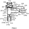
- FIG 3 shows an embodiment of a gas delivery device 2 according to the present invention that is useable, especially in emergency situations, for delivering a flow of oxygen when mounted on an oxygen source 1 (see Fig. 5 ), such as an oxygen cartridge 10, as shown in Figures 1 and 2 , or to any other suitable oxygen cylinder.
- an oxygen source 1 see Fig. 5
- an oxygen cartridge 10 such as an oxygen cartridge 10
- Figures 1 and 2 or to any other suitable oxygen cylinder.
- Said gas delivery device 2 comprises a hollow connecting portion 211a comprising an axial passage 210a for the gas having an inlet 210.
- the connecting portion 211a further comprises an external armature 200 that surrounds the peripheral outer wall 10b of the cartridge's upper end 10a, when the gas delivery device 2 is fixed to the cartridge's upper end 10a, as shown in Figures 5 , 6 and 8 .
- the inner wall 210b of the axial passage 210a comprises an inner threaded portion 211 that is complementary to the outer threaded portion 12 arranged on the oxygen cartridge 10 so that both threaded portions 211, 12 can cooperate and be coupled together for securing the gas delivery device 2 to the oxygen source 1.
- a hollow elongated stem 212 is axially arranged in the axial passage 210a and is securely attached to the inner wall 210b of the axial passage 210a of the armature 200 by a prolongation wall 215.
- the hollow elongated stem 212 ensures a fluidic communication between the inlet 210 and a main chamber 201 via a first stem port 212a and second stem port 212b located at the opposite ends of the stem inner passage 212c traversing the hollow elongated stem 212.
- the stem inner passage 212c further comprises a flow restriction, preferably a calibrated orifice 213 for limiting the flow of oxygen circulating into the stem inner passage 212c of the hollow elongated stem 212, in the direction of the main chamber 201.
- a flow restriction preferably a calibrated orifice 213 for limiting the flow of oxygen circulating into the stem inner passage 212c of the hollow elongated stem 212, in the direction of the main chamber 201.
- the diameter of the calibrated orifice 213 is of about 0.025 mm; of course, it could have a greater or lesser diameter.
- Main chamber 201 is in fluid communication with an inner gas passage 202a of an injection nozzle 202 arranged downstream of said main chamber 201.
- the main chamber 201 is prolonged by, at one of its end, an injection nozzle 202 having an inner conical or tronconical shape or structure, so that the gas exiting the main chamber 201 enters the inner gas passage 202a of the injection nozzle 202.
- Said inner gas passage 202a of conical or tronconical shape comprises an inlet diameter 203 located on the side of the main chamber 201, and an outlet diameter 204 located on the other side, the inlet diameter 203 being greater than the outlet diameter 204, preferably the inlet diameter 203 is at least 10 times the outlet diameter 204.
- the inlet diameter 203 can be of between 10 and 20 mm, whereas the outlet diameter 204 can be of between 0.3 and 0.4 mm.
- the outlet diameter 204 of the injection nozzle 202 is in fluid communication with a downstream chamber 233, such as the lumen 234a of a conduit 234, arranged downstream of the injection nozzle 202 so that gas delivered by the injection nozzle 202 is recovered by said downstream chamber 233, preferably a conduit 234, and circulates into the lumen 234a of said conduit 234.
- the particular structure of the injection nozzle 202 forms a Venturi system.
- the diameter decrease from inlet diameter 203 to outlet diameter 204 leads to an increase of the gas velocity traversing the injection nozzle 202 as well as a localized depression (i.e. a negative pressure) downstream of the outlet orifice 204, e.g. in downstream chamber 233.
- a negative pressure ensures an additional gas suction so that the flow of gas circulating in the downstream chamber 233, especially in the lumen 234a of conduit 234, is greater that the flow circulating in injection nozzle 202.
- Said downstream chamber 233 is further in fluid communication with the bag outlet 232 of an inflatable bag 230.
- said inflatable bag 230 is made of a flexible material, such as polyethylene (PE) or a combination of polyethylene and aluminum foils.
- said inflatable bag 230 also comprises a bag inlet 231.
- a connection conduct 222 fluidly links the bag inlet 231 to the exit port 222a of a second chamber 221 that is fluidly communicating with the main chamber 201, via outlet orifice 201a, as shown in Fig. 3 . Thanks to the connection conduct 222, the second chamber 221 is fluidly communicating with the inflatable bag 230 as explained below.
- a gas-flow control device 220, 224 is arranged between the main chamber 201 and the second chamber 221 for controlling the passage of gas from the main chamber 201 to the second chamber 221.
- the gas-flow control device 220, 224 comprises a flexible membrane 220 and an elastic element 224, such as a spring element, for instance a metallic spring, cooperating with the flexible membrane 220.
- the gas-flow control device 220, 224 is shown in Figures 4A-4E .
- membrane 220 is normally tightly closing the outlet orifice 201a located between main chamber 201 and second chamber 221 by resting via its lower surface 220c, on the peripheral edges 205 of the armature 200 that form an annular seat, thereby prohibiting any gas passage from the main chamber 201 to the second chamber 221.
- Membrane 220 is held in such a "closing position" thanks to the force applied by elastic element 224 that is embedded into a spring armature 223 fixed to the walls of the second chamber 221, and maintained therein by a closing cap 225.
- the elastic element 224 is normally pushing against the upper surface 220c of the membrane 220, i.e. in the direction of the main chamber 201.
- the membrane 220 is deformable. It comprises a lip portion 220a which is securely attached to a grove 223a arranged in the spring armature 223, and further a deformable portion 220b.
- the spring element 224 is designed so that, in the configuration of Fig. 4B , the opening pressure, e.g. pressure in chamber 201 which is sufficient to push the surface 220c of membrane 220 upwardly, is set to be of about 500 mbar.
- Said opening pressure depends on the specifications of the spring element 224 and its initial compression state defined by the position of roof plate 225a of closing cap 225 as shown in Fig. 4C .
- the threaded portion 225b of closing cap 225 and the complementary threaded portion 223b of spring armature 223 allow roof plate 225a moving downwardly or upwardly, when said closing cap 225 is more or less screwed onto spring armature 223 by a user.
- Fig. 4D which is a view from above of armature 223 and cap 225, includes guidance to the operator to set two opening pressures.
- the upper surface 225b of closing cap 225 embeds a marking, such as an arrow 225c or any other marking, which can be either embossed or printed in said upper surface 225b
- upper surface 223c of armature 223 shows, in the present embodiment, two positions, likewise either embossed or printed, namely position "3" 223d and position "6" 223e, that are diametrically opposed.
- Position "6" is taken below as an example in connection with Fig. 5 to 10 that show successive steps to be taken for securing a gas delivery device 2 according to the present invention to an oxygen source 1.
- Fig. 5 represents a first step of pairing/connecting the oxygen source 1 of Figure 1 to the gas delivery device 2 of Figure 3 .
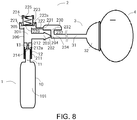
- a patient 4 is connected via breathing pathway 3 to the gas delivery device 2 of Fig. 3 , according to the present invention.
- the breathing pathway 3 comprises a gas conduct 31, such as a flexible hose, connected to conduit 234 of the delivery device 2 and ended by an interface 32, such as a nasal cannula or an oro-nasal mask as shown.
- the oxygen source 1 e.g.
- cartridge 10 is inserted into inlet 210 of the gas delivery device 2, and threaded portion 211 of armature 200 and threaded portion 12 of outlet 11 are put into contact and are screwed together for securing the gas delivery device 2 on oxygen source 1. This can be done by turning the canister 10 clockwise. In this initial step, the cap 13 of outlet 11 does not yet enter into contact with stem 212 so that the gas contained in internal volume 101 of cartridge 10 cannot escape.
- Fig. 6 represents a second step of the insertion of the oxygen source 1 by turning canister 10 further, clockwise. At this point, a contact between elongated stem 212 and cap 13 closing the outlet 11 of cartridge 10 has already taken place.
- the tip 214 of stem 212 i.e. its free end 212a, has punctured/pierced the cap 13 of cartridge 10 so that a fluidic connection is established between the internal volume 101 of canister 10 and main chamber 201 as the gas can circulates in the stem inner passage 212c traversing the hollow elongated stem 212, i.e. in the lumen of elongated stem 212, in the direction of the main chamber 201.
- the complementary threaded portions 211 and 12 securely maintain the canister 10 in position thereby preventing any damages that might arise with the compressed oxygen source 1.
- the resulting flow coming out of outlet 11 and circulating into stem 212 to fill the main chamber 201 can have an initial value of about 10L/min (flowrate), right after tip 214 of stem 212 punctured cap 13, to progressively decrease over the time, for reaching 2L/min after about 20 min of operation, as shown in Figure 7 .
- a pressure increase occurs in main chamber 201 as the gaseous flow traverses stem 212.
- This pressure rise mainly depends on the design of injection nozzle 202, especially its outlet diameter 204 as it creates an additional resistance to the flow coming from the internal volume 101 of canister 10.
- a diameter of about 0.035 mm of the outlet orifice 204 generates a back pressure of 500 mb if a flow of 1L/min passes through it. This is precisely the opening pressure of membrane 220 as described above, namely the position "6" of cap 225.
- liaison conduct 222 acts as a fluidic bridge between inlet 222a, in contact with second chamber 221, and inflatable bag 230 via inlet 231, a fluidic connection is made between main chamber 201 and bag 230. Consequently, as long as the flow coming from the oxygen source 1 is greater than 1L/min, the flow in excess is redirected from main chamber 201 into inflatable bag 230 that starts to inflate, as shown in Figure 9 .
- the pressure within main chamber 201 is of 500 mb, whereas the inflatable bag 230 collects the gas excess coming from oxygen source 1.
- the pressure (i.e. 500mb) at the inlet 203 of the injection nozzle 202 generates a flowrate of about 1 L/min that is ejected through outlet 204. Due to the fluid acceleration occurring in nozzle 202, a depression occurs in chamber 233 that draws gas out of inflatable bag 230 via outlet 232.
- the design of chamber 233 is such that for an incoming flow of 1 L/min in the nozzle 202 (e.g. 500mb at inlet 203), a 6-time increase is noticed in conduct 234. In other words, the depression created in chamber 233 draws an additional 5 L/min of gas that is combined with the incoming flow of 1 L/min to generate a total flow of 6 L/min, reaching patient 4 via the breathing pathway 3.
- the flow going into bag 230 becomes less than the flow of 5L/min drawn into chamber 233 via the Venturi effect.
- the accumulated volume in bag 230 can supply the demand and, as a consequence, while the flow reaching patient 4 remain steady at 6L/min, a deflation phase occurs.
- the volume Vb3 in bag 230 becomes null (i.e., equals zero) and the delivery device 2 is no longer able to provide the steady supply of 6 L/min that does progressively decrease until the canister 10 is empty.
- the cap 225 can be set on its position "3" which decreases the opening pressure of membrane 220 to, for instance, 200mb. This in turn largely affects the performances of the Venturi system made of nozzle 202 and chamber 233.
- the flow going into nozzle 202 and exiting through outlet orifice 204 is lowered in this setting to about 0.75 L/min, which also decreases the suction capacity of said Venturi system (the amount of flow drawn from bag 230 to chamber 233) from 6 to 4-fold. This results in a total flow of about 3L/min in conduct 234, reaching patient 4 via breathing pathway 3.
- a gas delivery device 2 according to the present invention can be from about 5 to 10 times cheaper than a pressure regulator according to the prior art, and is able to deliver steady flows of 3 or 6 L/min for about 20 minutes that is sufficient for the first responders to arrive and take care of the patient.
- a gas cylinder equipped with a gas delivery device 2 constitutes a rather compact assembly that can be used in emergency vehicles, such as in ambulances or the like.
Landscapes
- Health & Medical Sciences (AREA)
- Emergency Medicine (AREA)
- Pulmonology (AREA)
- Engineering & Computer Science (AREA)
- Anesthesiology (AREA)
- Biomedical Technology (AREA)
- Heart & Thoracic Surgery (AREA)
- Hematology (AREA)
- Life Sciences & Earth Sciences (AREA)
- Animal Behavior & Ethology (AREA)
- General Health & Medical Sciences (AREA)
- Public Health (AREA)
- Veterinary Medicine (AREA)
- Respiratory Apparatuses And Protective Means (AREA)
Abstract
Description
- The present invention concerns a gas delivery device or apparatus for delivering an oxygen gas flow to a person in need thereof, especially in an emergency situation.
- Oxygen is commonly administrated by inhalation for correcting a hypoxemia, e.g. an oxyhemoglobin saturation below normal ranges (e.g., < 85%) in a patient. Actually, oxygen is widely used for treating various patient populations, e.g. neonates to adult, as well as various medical conditions, e.g. pulmonary deficiencies, such as Acute Respiratory Distress Syndrome (ARDS), Chronic Obstructive Pulmonary Disease (COPD) or post-operative recovery only.
- In a hospital, oxygen is usually delivered through wall outlets or plugs fluidly connected to an oxygen source(s), for instance a large-volume vessel of liquid oxygen, and preferably a backup system, coupled to a vaporizer so as to ensure a continuous supply of gaseous oxygen to the patients of the hospital.
- Large-volume oxygen vessels are not available in emergency units, such as ambulances or the like, while numerous emergency situations require oxygen for treating the persons involved, e.g., car crash, cardiac arrest situation, pulmonary deficiencies.... In those emergency situations, the medical staff, such as doctors, nurses or the like, only relies on gas cylinders having a limited size, typically from 2 to 5 liter cylinders filled with medical grade compressed oxygen.
- The oxygen flow delivered by such a cylinder is set by the medical staff depending on the patient to be treated. For instance, it is usually to deliver a flow of 3L/min of oxygen to an infant and of 6 L/min to an adult. A pressure/flowrate regulator or valve arranged on the cylinder is usually used for setting the desired oxygen flowrate.
- However, if such regulators are highly effective, they are mechanically complex and rather expensive due to the presence of a calibrated-orifice plate mechanism for setting the flowrate arranged inside the regulator body or of other specific parts.
- A goal of the present invention is to propose a simpler and less expensive gas delivery device that can be arranged on a gas cylinder.
- Another goal of the present invention is to propose a gas delivery device that allows a delivery of steady flows of oxygen, preferably of between about 3 to about 6 L/min of oxygen, for a given period of time, preferably of at least 20 minutes.
- Another goal of the present invention is to propose a gas delivery device that is useable in emergency situations for treating people in need of oxygen gas.
- Another goal of the present invention is to propose a gas delivery device that does not include any calibrated-orifice plate mechanism as it is the case in pressure/flowrate regulators of the prior art.
- Another goal of the present invention is to propose a gas delivery device that is suitable for delivering oxygen gas to adults as well as to children in need thereof.
- A solution of the present invention comprises a gas delivery device or apparatus comprising:
- a main chamber,
- an injection nozzle comprising an inner gas passage in fluid communication with the main chamber, said inner gas passage comprising an inlet diameter and an outlet diameter, said inlet diameter being greater than the outlet diameter,
- a downstream chamber in fluid communication with the inner gas passage of the injection nozzle,
- an inflatable bag in fluid communication with the downstream chamber,
- a second chamber fluidly communicating with the main chamber and further with the inflatable bag, and
- a gas-flow control device arranged between the main chamber and the second chamber for controlling the passage of gas from the main chamber to the second chamber.
- Depending on the embodiment, a gas delivery device or apparatus according to the present invention can comprise one or several of the following features:
- the inner gas passage has a conical or tronconical shape, i.e., structure.
- the inner gas passage comprises or forms a Venturi system.
- the gas flow control device comprises a flexible membrane.
- the gas flow control device further comprises an elastic element cooperating with the flexible membrane.
- the flexible membrane is made of silicon
- the elastic element comprises a spring element.
- the inflatable bag is made of a flexible material, such as polyethylene (PE) or a combination of polyethylene and one or several aluminum foils.
- The invention also concerns a gas cylinder comprising a gas delivery device according to the present invention, such as an oxygen cylinder, preferably a oxygen cartridge.
- The present invention will be explained in more details in the following illustrative description of an embodiment of a gas delivery device according to the present invention mounted on an oxygen gas cylinder, which is made in references to the accompanying drawings among them:
-
Fig. 1 and 2 show two embodiments of an oxygen source useable with a gas delivery device according to the present invention, -
Fig. 3 shows an embodiment of a gas delivery device according to the present invention, -
Fig. 4A to 4E show a subset of the gas delivery device ofFig. 3 , -
Fig. 5 to 9 show the gas delivery device ofFig. 3 in use, when mounted on the oxygen source ofFig. 1 , and -
Fig. 10 represents the distribution of gas flows in the gas delivery device according to the present invention, during use. -
Fig.1 represents an embodiment of anoxygen source 1, preferably an oxygen cylinder, useable in the frame of the present invention. Theoxygen source 1 comprises adisposable cartridge 10, for instance made of an aluminum alloy, comprising, at itsupper end 10a, acartridge outlet 11 sealed by aclosing cap 13 so that the gas compressed in saidcartridge 10 cannot flow out of it. - An outer threaded
portion 12 is arranged in the peripheralouter wall 10b of the cartridge'supper end 10a for allowing securing a gas delivery device according to the present invention to theoxygen source 1. - The
internal volume 101 ofcartridge 10 is sized so as to contain, in this embodiment, about 0.5L of compressed oxygen at a pressure of 200 bars, preferably medical grade oxygen, thereby ensuring a delivery of about 120 L of oxygen, e.g. 6L/min for 20 minutes. Of course, thecartridge 10 could be sized for containing other volumes of compressed oxygen. -
Fig. 2 shows an alternative embodiment of theoxygen source 1 similar to the one ofclaim 1, except it further comprises a ball-system valve ball 13, preferably a metallic ball, loaded by aspring 14, for normally closing thecylinder outlet orifice 15. Such a ball-system valve closing cap 13 ofFigure 1 . -
Cartridges 10 according toFigures 1 and 2 will not be further detailed as they are well-known and available on the market. -
Figure 3 shows an embodiment of agas delivery device 2 according to the present invention that is useable, especially in emergency situations, for delivering a flow of oxygen when mounted on an oxygen source 1 (seeFig. 5 ), such as anoxygen cartridge 10, as shown inFigures 1 and 2 , or to any other suitable oxygen cylinder. - Said
gas delivery device 2 comprises a hollow connectingportion 211a comprising anaxial passage 210a for the gas having aninlet 210. The connectingportion 211a further comprises anexternal armature 200 that surrounds the peripheralouter wall 10b of the cartridge'supper end 10a, when thegas delivery device 2 is fixed to the cartridge'supper end 10a, as shown inFigures 5 ,6 and8 . - The
inner wall 210b of theaxial passage 210a comprises an inner threadedportion 211 that is complementary to the outer threadedportion 12 arranged on theoxygen cartridge 10 so that both threadedportions gas delivery device 2 to theoxygen source 1. - A hollow
elongated stem 212 is axially arranged in theaxial passage 210a and is securely attached to theinner wall 210b of theaxial passage 210a of thearmature 200 by aprolongation wall 215. The hollowelongated stem 212 ensures a fluidic communication between theinlet 210 and amain chamber 201 via afirst stem port 212a andsecond stem port 212b located at the opposite ends of the steminner passage 212c traversing the hollowelongated stem 212. - The stem
inner passage 212c further comprises a flow restriction, preferably acalibrated orifice 213 for limiting the flow of oxygen circulating into the steminner passage 212c of the hollowelongated stem 212, in the direction of themain chamber 201. For instance, the diameter of thecalibrated orifice 213 is of about 0.025 mm; of course, it could have a greater or lesser diameter. -
Main chamber 201 is in fluid communication with an inner gas passage 202a of aninjection nozzle 202 arranged downstream of saidmain chamber 201. In other words, themain chamber 201 is prolonged by, at one of its end, aninjection nozzle 202 having an inner conical or tronconical shape or structure, so that the gas exiting themain chamber 201 enters the inner gas passage 202a of theinjection nozzle 202. - Said inner gas passage 202a of conical or tronconical shape comprises an
inlet diameter 203 located on the side of themain chamber 201, and anoutlet diameter 204 located on the other side, theinlet diameter 203 being greater than theoutlet diameter 204, preferably theinlet diameter 203 is at least 10 times theoutlet diameter 204. For instance, theinlet diameter 203 can be of between 10 and 20 mm, whereas theoutlet diameter 204 can be of between 0.3 and 0.4 mm. - The
outlet diameter 204 of theinjection nozzle 202 is in fluid communication with adownstream chamber 233, such as thelumen 234a of aconduit 234, arranged downstream of theinjection nozzle 202 so that gas delivered by theinjection nozzle 202 is recovered by saiddownstream chamber 233, preferably aconduit 234, and circulates into thelumen 234a of saidconduit 234. - The particular structure of the
injection nozzle 202 forms a Venturi system. The diameter decrease frominlet diameter 203 tooutlet diameter 204 leads to an increase of the gas velocity traversing theinjection nozzle 202 as well as a localized depression (i.e. a negative pressure) downstream of theoutlet orifice 204, e.g. indownstream chamber 233. Such a negative pressure ensures an additional gas suction so that the flow of gas circulating in thedownstream chamber 233, especially in thelumen 234a ofconduit 234, is greater that the flow circulating ininjection nozzle 202. - Said
downstream chamber 233, especially in thelumen 234a ofconduit 234, is further in fluid communication with thebag outlet 232 of aninflatable bag 230. Preferably, saidinflatable bag 230 is made of a flexible material, such as polyethylene (PE) or a combination of polyethylene and aluminum foils. - Further, said
inflatable bag 230 also comprises abag inlet 231. Aconnection conduct 222 fluidly links thebag inlet 231 to theexit port 222a of asecond chamber 221 that is fluidly communicating with themain chamber 201, viaoutlet orifice 201a, as shown inFig. 3 . Thanks to theconnection conduct 222, thesecond chamber 221 is fluidly communicating with theinflatable bag 230 as explained below. - Further, a gas-
flow control device main chamber 201 and thesecond chamber 221 for controlling the passage of gas from themain chamber 201 to thesecond chamber 221. In one embodiment, the gas-flow control device flexible membrane 220 and anelastic element 224, such as a spring element, for instance a metallic spring, cooperating with theflexible membrane 220. - The gas-
flow control device Figures 4A-4E . - As shown in
Fig. 4A ,membrane 220 is normally tightly closing theoutlet orifice 201a located betweenmain chamber 201 andsecond chamber 221 by resting via itslower surface 220c, on theperipheral edges 205 of thearmature 200 that form an annular seat, thereby prohibiting any gas passage from themain chamber 201 to thesecond chamber 221.Membrane 220 is held in such a "closing position" thanks to the force applied byelastic element 224 that is embedded into aspring armature 223 fixed to the walls of thesecond chamber 221, and maintained therein by aclosing cap 225. - The
elastic element 224 is normally pushing against theupper surface 220c of themembrane 220, i.e. in the direction of themain chamber 201. Themembrane 220 is deformable. It comprises alip portion 220a which is securely attached to a grove 223a arranged in thespring armature 223, and further adeformable portion 220b. - Whenever the gas force acting on the lower surface 220c1 of
membrane 220, which is related to the pressure inchamber 201, is greater than the force developed by thespring element 224, thedeformable portion 220b ofmembrane 220 executes an upward movement which in turns lifts itsupper surface 220c, as shown inFig. 4B . - As a result, a fluidic pathway is created between
chambers outlet orifice 201a, and consequently with the lumen of theconnection conduct 222, thereby allowing gas to circulate successively inmain chamber 201,second chamber 221,connection conduct 222 andinflatable bag 230. - The
spring element 224 is designed so that, in the configuration ofFig. 4B , the opening pressure, e.g. pressure inchamber 201 which is sufficient to push thesurface 220c ofmembrane 220 upwardly, is set to be of about 500 mbar. - Said opening pressure depends on the specifications of the
spring element 224 and its initial compression state defined by the position ofroof plate 225a ofclosing cap 225 as shown inFig. 4C . Indeed, the threadedportion 225b ofclosing cap 225 and the complementary threadedportion 223b ofspring armature 223 allowroof plate 225a moving downwardly or upwardly, when saidclosing cap 225 is more or less screwed ontospring armature 223 by a user. - These up or down motions will set a length of
spring 224 as defined by the distance betweenroof plate 225a andupper surface 220c ofmembrane 220, that sets the opening pressure. - As an example,
Fig. 4D , which is a view from above ofarmature 223 andcap 225, includes guidance to the operator to set two opening pressures. Thus, theupper surface 225b ofclosing cap 225 embeds a marking, such as anarrow 225c or any other marking, which can be either embossed or printed in saidupper surface 225b, whereasupper surface 223c ofarmature 223 shows, in the present embodiment, two positions, likewise either embossed or printed, namely position "3" 223d and position "6" 223e, that are diametrically opposed. - By turning/screwing
closing cap 225 so as to makearrow 225c coincide with position "3" 223d as shown inFig. 4D or with position "6" 223e as shown inFig. 4E , the user is able to set a desired opening pressure corresponding to either positions, for instance a pressure of about 200mb in position "3" and of about "500mb" in position "6". - Position "6" is taken below as an example in connection with
Fig. 5 to 10 that show successive steps to be taken for securing agas delivery device 2 according to the present invention to anoxygen source 1. -
Fig. 5 represents a first step of pairing/connecting theoxygen source 1 ofFigure 1 to thegas delivery device 2 ofFigure 3 . InFig. 5 , apatient 4 is connected via breathingpathway 3 to thegas delivery device 2 ofFig. 3 , according to the present invention. Thebreathing pathway 3 comprises agas conduct 31, such as a flexible hose, connected toconduit 234 of thedelivery device 2 and ended by aninterface 32, such as a nasal cannula or an oro-nasal mask as shown. As one can see, theoxygen source 1,e.g. cartridge 10, is inserted intoinlet 210 of thegas delivery device 2, and threadedportion 211 ofarmature 200 and threadedportion 12 ofoutlet 11 are put into contact and are screwed together for securing thegas delivery device 2 onoxygen source 1. This can be done by turning thecanister 10 clockwise. In this initial step, thecap 13 ofoutlet 11 does not yet enter into contact withstem 212 so that the gas contained ininternal volume 101 ofcartridge 10 cannot escape. -
Fig. 6 represents a second step of the insertion of theoxygen source 1 by turningcanister 10 further, clockwise. At this point, a contact betweenelongated stem 212 andcap 13 closing theoutlet 11 ofcartridge 10 has already taken place. - Actually, the
tip 214 ofstem 212, i.e. itsfree end 212a, has punctured/pierced thecap 13 ofcartridge 10 so that a fluidic connection is established between theinternal volume 101 ofcanister 10 andmain chamber 201 as the gas can circulates in the steminner passage 212c traversing the hollowelongated stem 212, i.e. in the lumen ofelongated stem 212, in the direction of themain chamber 201. The complementary threadedportions canister 10 in position thereby preventing any damages that might arise with the compressedoxygen source 1. - As the puncture of
cap 13 just happened (at t=0 sec) inFig. 6 , the elements located downstream ofstem 212 are still in their native configuration (i.e., as inFig. 5 ), namelymain chamber 201 is at ambient conditions,membrane 220 tightly closes the fluidic pathway between saidmain chamber 201 andsecond chamber 221, and no gaseous flow is traversing theinjection nozzle 202. - Calibrated
orifice 213, arranged instem 212, acts as a flow limiter to prevent an excessive amount of gas flowing out ofcanister 10. - Based on the dimensions of
orifice 213 and assuming aninternal volume 101 ofcanister 10 with an initial filling pressure of 200 bars, the resulting flow coming out ofoutlet 11 and circulating intostem 212 to fill themain chamber 201, can have an initial value of about 10L/min (flowrate), right aftertip 214 ofstem 212 puncturedcap 13, to progressively decrease over the time, for reaching 2L/min after about 20 min of operation, as shown inFigure 7 . - Once a flow of oxygen leaves the
oxygen source 1, a pressure increase occurs inmain chamber 201 as the gaseous flow traversesstem 212. This pressure rise mainly depends on the design ofinjection nozzle 202, especially itsoutlet diameter 204 as it creates an additional resistance to the flow coming from theinternal volume 101 ofcanister 10. As an example, a diameter of about 0.035 mm of theoutlet orifice 204 generates a back pressure of 500 mb if a flow of 1L/min passes through it. This is precisely the opening pressure ofmembrane 220 as described above, namely the position "6" ofcap 225. In other words, if the flow coming from the oxygen source is greater than 1 L/min, a fluidic connection between main andsecond chambers Fig. 8 and the pressure withinmain chamber 201 remains steady at the opening pressure of 500 mb. - Furthermore, as
liaison conduct 222 acts as a fluidic bridge betweeninlet 222a, in contact withsecond chamber 221, andinflatable bag 230 viainlet 231, a fluidic connection is made betweenmain chamber 201 andbag 230. Consequently, as long as the flow coming from theoxygen source 1 is greater than 1L/min, the flow in excess is redirected frommain chamber 201 intoinflatable bag 230 that starts to inflate, as shown inFigure 9 . - The pressure within
main chamber 201 is of 500 mb, whereas theinflatable bag 230 collects the gas excess coming fromoxygen source 1. The pressure (i.e. 500mb) at theinlet 203 of theinjection nozzle 202 generates a flowrate of about 1 L/min that is ejected throughoutlet 204. Due to the fluid acceleration occurring innozzle 202, a depression occurs inchamber 233 that draws gas out ofinflatable bag 230 viaoutlet 232. The design ofchamber 233 is such that for an incoming flow of 1 L/min in the nozzle 202 (e.g. 500mb at inlet 203), a 6-time increase is noticed inconduct 234. In other words, the depression created inchamber 233 draws an additional 5 L/min of gas that is combined with the incoming flow of 1 L/min to generate a total flow of 6 L/min, reachingpatient 4 via thebreathing pathway 3. - As can be seen in
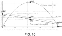
Figure 10 , the flow coming fromoxygen source 1 is of about 10 L/min (Qs1) at the onset of the delivery (t=0) to about 2 L/min (Qs3) after 20 min of operation (t=1200s). - This means that enough flow is generated over the course of the operation to have 1 L/min crossing the
injection nozzle 202 and therefore reaches the opening pressure of 500 mb inmain chamber 201. As a result, an initial flow Qb1 of 9L/min (10 L/min - 1L/min) fills theinflatable bag 230 as above explained. - As the design of the Venturi made of
injection nozzle 202 andsecond chamber 233 draws 5L/min frombag 230 for such operating conditions, a remaining 4L/min flow (i.e. 9L/min - 5L/min) is in excess and stays inbag 230. This is the inflation phase. As long as the flow coming from theoxygen source 1 is greater than 6 L/min, i.e. between Qs1 and Qs2, thebag 230 inflates to start from an initial value of 0 L (Vb1) to a maximum value of about 17 L (Vb2) after 10 minutes (t=600s). During these first 10 minutes, the flow traveling intoconduit 234 and reachingpatient 4 viabreathing pathway 3 equals 6L/min. - Once the flow coming from
oxygen source 1 is less than 6L/min (Qs2), the flow going into bag 230 (Qb2) becomes less than the flow of 5L/min drawn intochamber 233 via the Venturi effect. The accumulated volume inbag 230 can supply the demand and, as a consequence, while theflow reaching patient 4 remain steady at 6L/min, a deflation phase occurs. After about 20 min (t=1200s) the volume Vb3 inbag 230 becomes null (i.e., equals zero) and thedelivery device 2 is no longer able to provide the steady supply of 6 L/min that does progressively decrease until thecanister 10 is empty. - As described in
Figure 4D thecap 225 can be set on its position "3" which decreases the opening pressure ofmembrane 220 to, for instance, 200mb. This in turn largely affects the performances of the Venturi system made ofnozzle 202 andchamber 233. The flow going intonozzle 202 and exiting throughoutlet orifice 204 is lowered in this setting to about 0.75 L/min, which also decreases the suction capacity of said Venturi system (the amount of flow drawn frombag 230 to chamber 233) from 6 to 4-fold. This results in a total flow of about 3L/min inconduct 234, reachingpatient 4 viabreathing pathway 3. - More generally speaking, a
gas delivery device 2 according to the present invention can be from about 5 to 10 times cheaper than a pressure regulator according to the prior art, and is able to deliver steady flows of 3 or 6 L/min for about 20 minutes that is sufficient for the first responders to arrive and take care of the patient. - Of course, higher flows can be obtained with the
gas delivery device 2 according to the present invention, for instance 12 L/min in case of critical emergency such as cardiac arrest, by modifying the diameter oforifice 213, increasing theinternal volume 101 ofcanister 10 and opening pressure ofmembrane 220. - Further, a gas cylinder equipped with a
gas delivery device 2 according to the present invention constitutes a rather compact assembly that can be used in emergency vehicles, such as in ambulances or the like.
Claims (11)
- Gas delivery device (2) comprising:- a main chamber (201),- an injection nozzle (202) comprising an inner gas passage (202a) in fluid communication with the main chamber (201), said inner gas passage (202a) comprising an inlet diameter (203) and an outlet diameter (204), said inlet diameter (203) being greater than the outlet diameter (204),- a downstream chamber (233) in fluid communication with the inner gas passage (202a) of the injection nozzle (202),- an inflatable bag (230) in fluid communication with the downstream chamber (233),- a second chamber (221) fluidly communicating with the main chamber (201) and further with the inflatable bag (230), and- a gas-flow control device (220, 224) arranged between the main chamber (201) and the second chamber (221) for controlling the passage of gas from the main chamber (201) to the second chamber (221).
- Gas delivery device (2) according to the preceding claim, characterized in that the inner gas passage (202a) has a conical or tronconical shape.
- Gas delivery device (2) according to any one of the preceding claims, characterized in that the gas flow control device (220, 224) comprises a flexible membrane (220).
- Gas delivery device (2) according to any one of the preceding claims, characterized in that the gas flow control device (220, 224) further comprises an elastic element cooperating with a flexible membrane (220).
- Gas delivery device (2) according to any one of the preceding claims, characterized in that the inflatable bag (230) is in fluid communication with the second chamber (221) through a connection conduct (222).
- Gas delivery device (2) according to any one of the preceding claims, characterized in that the flexible membrane (220) is made of silicon.
- Gas delivery device (2) according to any one of the preceding claims, characterized in that the elastic element comprises a spring element.
- Gas delivery device (2) according to any one of the preceding claims, characterized in that the inflatable bag (230) is made of a flexible material.
- Gas delivery device (2) according to any one of the preceding claims, characterized in that the flexible inflatable bag (230) is made of polyethylene (PE) or a combination of polyethylene and one or several aluminum foils.
- Gas cylinder comprising a gas delivery device (2) according to any one of the preceding claims.
- Gas cylinder according to claim 10, characterized in that it is an oxygen cylinder or oxygen cartridge (10).
Applications Claiming Priority (1)
| Application Number | Priority Date | Filing Date | Title |
|---|---|---|---|
| US201862634335P | 2018-02-23 | 2018-02-23 |
Publications (2)
| Publication Number | Publication Date |
|---|---|
| EP3530308A1 true EP3530308A1 (en) | 2019-08-28 |
| EP3530308B1 EP3530308B1 (en) | 2021-05-12 |
Family
ID=65529296
Family Applications (1)
| Application Number | Title | Priority Date | Filing Date |
|---|---|---|---|
| EP19158119.8A Active EP3530308B1 (en) | 2018-02-23 | 2019-02-19 | Emergency oxygen delivery device |
Country Status (1)
| Country | Link |
|---|---|
| EP (1) | EP3530308B1 (en) |
Cited By (1)
| Publication number | Priority date | Publication date | Assignee | Title |
|---|---|---|---|---|
| CN114073794A (en) * | 2020-08-14 | 2022-02-22 | 刘齐山 | Oxygen controller and automatic control system |
Citations (5)
| Publication number | Priority date | Publication date | Assignee | Title |
|---|---|---|---|---|
| GB806471A (en) * | 1955-01-03 | 1958-12-23 | John Henry Blease | Improvements in or relating to assisted and artificial respiration, anaesthesia and the like |
| US4573462A (en) * | 1983-04-16 | 1986-03-04 | Dragerwerk Aktiengesellschaft | Respiratory system |
| US4883051A (en) * | 1988-02-18 | 1989-11-28 | Summa Vest, Inc. | Disposable breathing system and components |
| WO2004064907A1 (en) * | 2003-01-17 | 2004-08-05 | Unisearch Limited | A respiratory assist device and method of providing respiratory assistance |
| EP3019228A1 (en) * | 2013-07-10 | 2016-05-18 | Ventinova Technologies E.V. | Gas flow reversing element with bypass and method for controlling expiration of a patient |
-
2019
- 2019-02-19 EP EP19158119.8A patent/EP3530308B1/en active Active
Patent Citations (5)
| Publication number | Priority date | Publication date | Assignee | Title |
|---|---|---|---|---|
| GB806471A (en) * | 1955-01-03 | 1958-12-23 | John Henry Blease | Improvements in or relating to assisted and artificial respiration, anaesthesia and the like |
| US4573462A (en) * | 1983-04-16 | 1986-03-04 | Dragerwerk Aktiengesellschaft | Respiratory system |
| US4883051A (en) * | 1988-02-18 | 1989-11-28 | Summa Vest, Inc. | Disposable breathing system and components |
| WO2004064907A1 (en) * | 2003-01-17 | 2004-08-05 | Unisearch Limited | A respiratory assist device and method of providing respiratory assistance |
| EP3019228A1 (en) * | 2013-07-10 | 2016-05-18 | Ventinova Technologies E.V. | Gas flow reversing element with bypass and method for controlling expiration of a patient |
Cited By (1)
| Publication number | Priority date | Publication date | Assignee | Title |
|---|---|---|---|---|
| CN114073794A (en) * | 2020-08-14 | 2022-02-22 | 刘齐山 | Oxygen controller and automatic control system |
Also Published As
| Publication number | Publication date |
|---|---|
| EP3530308B1 (en) | 2021-05-12 |
Similar Documents
| Publication | Publication Date | Title |
|---|---|---|
| US20220296832A1 (en) | Optimized Breathing Assistance Device | |
| JP5095634B2 (en) | Breathing apparatus | |
| US6253767B1 (en) | Gas concentrator | |
| EP1410821B1 (en) | Breathable gas supply apparatus | |
| EP2656868A2 (en) | Breathing assistance apparatus | |
| US9072854B2 (en) | Reservoir system for gas delivery to a patient | |
| JP2000051360A (en) | Breathing aid | |
| US20130032153A1 (en) | Mask for an air delivery apparatus, system, and method | |
| US20130192597A1 (en) | Reservoir System for Gas Delivery to a Patient | |
| JP2001519213A (en) | Lung pressure modulator | |
| ES2957324T3 (en) | Gas supply device with deformable bag and differential pressure sensors | |
| KR102231592B1 (en) | Disposable Mechanical Ventilator | |
| CN111315449A (en) | Portable cyclic breathing system with staged oxygen enrichment addition | |
| AU2014336976A1 (en) | Improved oxygenating apparatus | |
| US20060124130A1 (en) | Ventilation system for respiratory devices | |
| US20170028151A1 (en) | Nasal cannula assembly with inhalation valves communicating with a deformable reservoir | |
| EP3530308B1 (en) | Emergency oxygen delivery device | |
| US12329912B2 (en) | Installation for supplying therapeutic gas to a patient while taking account of the losses of leaktightness at the mask | |
| EP2063947A2 (en) | Nebuliser valve | |
| ES2621352T3 (en) | Respiratory assist device, nasal apparatus and respiratory assistance mask | |
| EP3202449B1 (en) | Elbow connector assembly with anti-asphyxia valve structure for respiratory mask | |
| US12318547B2 (en) | Apparatus for supplying therapeutic gas to a patient, with control of the pressure at the mask | |
| US10953174B2 (en) | Pneumatic no delivery device | |
| WO2018151826A1 (en) | Method and system for gas delivery including gas conserver | |
| ES3040947T3 (en) | Closed-circuit breathing gas supply facility |
Legal Events
| Date | Code | Title | Description |
|---|---|---|---|
| PUAI | Public reference made under article 153(3) epc to a published international application that has entered the european phase |
Free format text: ORIGINAL CODE: 0009012 |
|
| STAA | Information on the status of an ep patent application or granted ep patent |
Free format text: STATUS: THE APPLICATION HAS BEEN PUBLISHED |
|
| AK | Designated contracting states |
Kind code of ref document: A1 Designated state(s): AL AT BE BG CH CY CZ DE DK EE ES FI FR GB GR HR HU IE IS IT LI LT LU LV MC MK MT NL NO PL PT RO RS SE SI SK SM TR |
|
| AX | Request for extension of the european patent |
Extension state: BA ME |
|
| STAA | Information on the status of an ep patent application or granted ep patent |
Free format text: STATUS: REQUEST FOR EXAMINATION WAS MADE |
|
| 17P | Request for examination filed |
Effective date: 20200228 |
|
| RBV | Designated contracting states (corrected) |
Designated state(s): AL AT BE BG CH CY CZ DE DK EE ES FI FR GB GR HR HU IE IS IT LI LT LU LV MC MK MT NL NO PL PT RO RS SE SI SK SM TR |
|
| GRAP | Despatch of communication of intention to grant a patent |
Free format text: ORIGINAL CODE: EPIDOSNIGR1 |
|
| STAA | Information on the status of an ep patent application or granted ep patent |
Free format text: STATUS: GRANT OF PATENT IS INTENDED |
|
| RIN1 | Information on inventor provided before grant (corrected) |
Inventor name: BOULANGER, THIERRY |
|
| INTG | Intention to grant announced |
Effective date: 20210125 |
|
| GRAS | Grant fee paid |
Free format text: ORIGINAL CODE: EPIDOSNIGR3 |
|
| GRAA | (expected) grant |
Free format text: ORIGINAL CODE: 0009210 |
|
| STAA | Information on the status of an ep patent application or granted ep patent |
Free format text: STATUS: THE PATENT HAS BEEN GRANTED |
|
| AK | Designated contracting states |
Kind code of ref document: B1 Designated state(s): AL AT BE BG CH CY CZ DE DK EE ES FI FR GB GR HR HU IE IS IT LI LT LU LV MC MK MT NL NO PL PT RO RS SE SI SK SM TR |
|
| REG | Reference to a national code |
Ref country code: GB Ref legal event code: FG4D |
|
| REG | Reference to a national code |
Ref country code: CH Ref legal event code: EP |
|
| REG | Reference to a national code |
Ref country code: DE Ref legal event code: R096 Ref document number: 602019004519 Country of ref document: DE |
|
| REG | Reference to a national code |
Ref country code: IE Ref legal event code: FG4D |
|
| REG | Reference to a national code |
Ref country code: AT Ref legal event code: REF Ref document number: 1391764 Country of ref document: AT Kind code of ref document: T Effective date: 20210615 |
|
| REG | Reference to a national code |
Ref country code: LT Ref legal event code: MG9D |
|
| REG | Reference to a national code |
Ref country code: AT Ref legal event code: MK05 Ref document number: 1391764 Country of ref document: AT Kind code of ref document: T Effective date: 20210512 |
|
| REG | Reference to a national code |
Ref country code: NL Ref legal event code: MP Effective date: 20210512 |
|
| PG25 | Lapsed in a contracting state [announced via postgrant information from national office to epo] |
Ref country code: LT Free format text: LAPSE BECAUSE OF FAILURE TO SUBMIT A TRANSLATION OF THE DESCRIPTION OR TO PAY THE FEE WITHIN THE PRESCRIBED TIME-LIMIT Effective date: 20210512 Ref country code: HR Free format text: LAPSE BECAUSE OF FAILURE TO SUBMIT A TRANSLATION OF THE DESCRIPTION OR TO PAY THE FEE WITHIN THE PRESCRIBED TIME-LIMIT Effective date: 20210512 Ref country code: FI Free format text: LAPSE BECAUSE OF FAILURE TO SUBMIT A TRANSLATION OF THE DESCRIPTION OR TO PAY THE FEE WITHIN THE PRESCRIBED TIME-LIMIT Effective date: 20210512 Ref country code: BG Free format text: LAPSE BECAUSE OF FAILURE TO SUBMIT A TRANSLATION OF THE DESCRIPTION OR TO PAY THE FEE WITHIN THE PRESCRIBED TIME-LIMIT Effective date: 20210812 Ref country code: AT Free format text: LAPSE BECAUSE OF FAILURE TO SUBMIT A TRANSLATION OF THE DESCRIPTION OR TO PAY THE FEE WITHIN THE PRESCRIBED TIME-LIMIT Effective date: 20210512 |
|
| PG25 | Lapsed in a contracting state [announced via postgrant information from national office to epo] |
Ref country code: GR Free format text: LAPSE BECAUSE OF FAILURE TO SUBMIT A TRANSLATION OF THE DESCRIPTION OR TO PAY THE FEE WITHIN THE PRESCRIBED TIME-LIMIT Effective date: 20210813 Ref country code: IS Free format text: LAPSE BECAUSE OF FAILURE TO SUBMIT A TRANSLATION OF THE DESCRIPTION OR TO PAY THE FEE WITHIN THE PRESCRIBED TIME-LIMIT Effective date: 20210912 Ref country code: PT Free format text: LAPSE BECAUSE OF FAILURE TO SUBMIT A TRANSLATION OF THE DESCRIPTION OR TO PAY THE FEE WITHIN THE PRESCRIBED TIME-LIMIT Effective date: 20210913 Ref country code: SE Free format text: LAPSE BECAUSE OF FAILURE TO SUBMIT A TRANSLATION OF THE DESCRIPTION OR TO PAY THE FEE WITHIN THE PRESCRIBED TIME-LIMIT Effective date: 20210512 Ref country code: RS Free format text: LAPSE BECAUSE OF FAILURE TO SUBMIT A TRANSLATION OF THE DESCRIPTION OR TO PAY THE FEE WITHIN THE PRESCRIBED TIME-LIMIT Effective date: 20210512 Ref country code: PL Free format text: LAPSE BECAUSE OF FAILURE TO SUBMIT A TRANSLATION OF THE DESCRIPTION OR TO PAY THE FEE WITHIN THE PRESCRIBED TIME-LIMIT Effective date: 20210512 Ref country code: NO Free format text: LAPSE BECAUSE OF FAILURE TO SUBMIT A TRANSLATION OF THE DESCRIPTION OR TO PAY THE FEE WITHIN THE PRESCRIBED TIME-LIMIT Effective date: 20210812 Ref country code: LV Free format text: LAPSE BECAUSE OF FAILURE TO SUBMIT A TRANSLATION OF THE DESCRIPTION OR TO PAY THE FEE WITHIN THE PRESCRIBED TIME-LIMIT Effective date: 20210512 |
|
| PG25 | Lapsed in a contracting state [announced via postgrant information from national office to epo] |
Ref country code: NL Free format text: LAPSE BECAUSE OF FAILURE TO SUBMIT A TRANSLATION OF THE DESCRIPTION OR TO PAY THE FEE WITHIN THE PRESCRIBED TIME-LIMIT Effective date: 20210512 |
|
| PG25 | Lapsed in a contracting state [announced via postgrant information from national office to epo] |
Ref country code: CZ Free format text: LAPSE BECAUSE OF FAILURE TO SUBMIT A TRANSLATION OF THE DESCRIPTION OR TO PAY THE FEE WITHIN THE PRESCRIBED TIME-LIMIT Effective date: 20210512 Ref country code: DK Free format text: LAPSE BECAUSE OF FAILURE TO SUBMIT A TRANSLATION OF THE DESCRIPTION OR TO PAY THE FEE WITHIN THE PRESCRIBED TIME-LIMIT Effective date: 20210512 Ref country code: SM Free format text: LAPSE BECAUSE OF FAILURE TO SUBMIT A TRANSLATION OF THE DESCRIPTION OR TO PAY THE FEE WITHIN THE PRESCRIBED TIME-LIMIT Effective date: 20210512 Ref country code: RO Free format text: LAPSE BECAUSE OF FAILURE TO SUBMIT A TRANSLATION OF THE DESCRIPTION OR TO PAY THE FEE WITHIN THE PRESCRIBED TIME-LIMIT Effective date: 20210512 Ref country code: EE Free format text: LAPSE BECAUSE OF FAILURE TO SUBMIT A TRANSLATION OF THE DESCRIPTION OR TO PAY THE FEE WITHIN THE PRESCRIBED TIME-LIMIT Effective date: 20210512 Ref country code: ES Free format text: LAPSE BECAUSE OF FAILURE TO SUBMIT A TRANSLATION OF THE DESCRIPTION OR TO PAY THE FEE WITHIN THE PRESCRIBED TIME-LIMIT Effective date: 20210512 Ref country code: SK Free format text: LAPSE BECAUSE OF FAILURE TO SUBMIT A TRANSLATION OF THE DESCRIPTION OR TO PAY THE FEE WITHIN THE PRESCRIBED TIME-LIMIT Effective date: 20210512 |
|
| REG | Reference to a national code |
Ref country code: DE Ref legal event code: R097 Ref document number: 602019004519 Country of ref document: DE |
|
| PLBE | No opposition filed within time limit |
Free format text: ORIGINAL CODE: 0009261 |
|
| STAA | Information on the status of an ep patent application or granted ep patent |
Free format text: STATUS: NO OPPOSITION FILED WITHIN TIME LIMIT |
|
| 26N | No opposition filed |
Effective date: 20220215 |
|
| PG25 | Lapsed in a contracting state [announced via postgrant information from national office to epo] |
Ref country code: IS Free format text: LAPSE BECAUSE OF FAILURE TO SUBMIT A TRANSLATION OF THE DESCRIPTION OR TO PAY THE FEE WITHIN THE PRESCRIBED TIME-LIMIT Effective date: 20210912 Ref country code: AL Free format text: LAPSE BECAUSE OF FAILURE TO SUBMIT A TRANSLATION OF THE DESCRIPTION OR TO PAY THE FEE WITHIN THE PRESCRIBED TIME-LIMIT Effective date: 20210512 |
|
| PG25 | Lapsed in a contracting state [announced via postgrant information from national office to epo] |
Ref country code: IT Free format text: LAPSE BECAUSE OF FAILURE TO SUBMIT A TRANSLATION OF THE DESCRIPTION OR TO PAY THE FEE WITHIN THE PRESCRIBED TIME-LIMIT Effective date: 20210512 |
|
| PG25 | Lapsed in a contracting state [announced via postgrant information from national office to epo] |
Ref country code: MC Free format text: LAPSE BECAUSE OF FAILURE TO SUBMIT A TRANSLATION OF THE DESCRIPTION OR TO PAY THE FEE WITHIN THE PRESCRIBED TIME-LIMIT Effective date: 20210512 |
|
| REG | Reference to a national code |
Ref country code: CH Ref legal event code: PL |
|
| REG | Reference to a national code |
Ref country code: BE Ref legal event code: MM Effective date: 20220228 |
|
| PG25 | Lapsed in a contracting state [announced via postgrant information from national office to epo] |
Ref country code: LU Free format text: LAPSE BECAUSE OF NON-PAYMENT OF DUE FEES Effective date: 20220219 |
|
| PG25 | Lapsed in a contracting state [announced via postgrant information from national office to epo] |
Ref country code: LI Free format text: LAPSE BECAUSE OF NON-PAYMENT OF DUE FEES Effective date: 20220228 Ref country code: IE Free format text: LAPSE BECAUSE OF NON-PAYMENT OF DUE FEES Effective date: 20220219 Ref country code: CH Free format text: LAPSE BECAUSE OF NON-PAYMENT OF DUE FEES Effective date: 20220228 |
|
| PG25 | Lapsed in a contracting state [announced via postgrant information from national office to epo] |
Ref country code: BE Free format text: LAPSE BECAUSE OF NON-PAYMENT OF DUE FEES Effective date: 20220228 |
|
| GBPC | Gb: european patent ceased through non-payment of renewal fee |
Effective date: 20230219 |
|
| PG25 | Lapsed in a contracting state [announced via postgrant information from national office to epo] |
Ref country code: GB Free format text: LAPSE BECAUSE OF NON-PAYMENT OF DUE FEES Effective date: 20230219 |
|
| PG25 | Lapsed in a contracting state [announced via postgrant information from national office to epo] |
Ref country code: GB Free format text: LAPSE BECAUSE OF NON-PAYMENT OF DUE FEES Effective date: 20230219 |
|
| PG25 | Lapsed in a contracting state [announced via postgrant information from national office to epo] |
Ref country code: MK Free format text: LAPSE BECAUSE OF FAILURE TO SUBMIT A TRANSLATION OF THE DESCRIPTION OR TO PAY THE FEE WITHIN THE PRESCRIBED TIME-LIMIT Effective date: 20210512 Ref country code: CY Free format text: LAPSE BECAUSE OF FAILURE TO SUBMIT A TRANSLATION OF THE DESCRIPTION OR TO PAY THE FEE WITHIN THE PRESCRIBED TIME-LIMIT Effective date: 20210512 |
|
| PG25 | Lapsed in a contracting state [announced via postgrant information from national office to epo] |
Ref country code: HU Free format text: LAPSE BECAUSE OF FAILURE TO SUBMIT A TRANSLATION OF THE DESCRIPTION OR TO PAY THE FEE WITHIN THE PRESCRIBED TIME-LIMIT; INVALID AB INITIO Effective date: 20190219 |
|
| PG25 | Lapsed in a contracting state [announced via postgrant information from national office to epo] |
Ref country code: TR Free format text: LAPSE BECAUSE OF FAILURE TO SUBMIT A TRANSLATION OF THE DESCRIPTION OR TO PAY THE FEE WITHIN THE PRESCRIBED TIME-LIMIT Effective date: 20210512 |
|
| PG25 | Lapsed in a contracting state [announced via postgrant information from national office to epo] |
Ref country code: MT Free format text: LAPSE BECAUSE OF FAILURE TO SUBMIT A TRANSLATION OF THE DESCRIPTION OR TO PAY THE FEE WITHIN THE PRESCRIBED TIME-LIMIT Effective date: 20210512 |
|
| PGFP | Annual fee paid to national office [announced via postgrant information from national office to epo] |
Ref country code: DE Payment date: 20260218 Year of fee payment: 8 |
|
| PGFP | Annual fee paid to national office [announced via postgrant information from national office to epo] |
Ref country code: FR Payment date: 20260218 Year of fee payment: 8 |