EP3530301A1 - Degasser and vent manifolds for dialysis - Google Patents
Degasser and vent manifolds for dialysis Download PDFInfo
- Publication number
- EP3530301A1 EP3530301A1 EP19158804.5A EP19158804A EP3530301A1 EP 3530301 A1 EP3530301 A1 EP 3530301A1 EP 19158804 A EP19158804 A EP 19158804A EP 3530301 A1 EP3530301 A1 EP 3530301A1
- Authority
- EP
- European Patent Office
- Prior art keywords
- fluid
- degasser
- outlet
- manifold
- pump
- Prior art date
- Legal status (The legal status is an assumption and is not a legal conclusion. Google has not performed a legal analysis and makes no representation as to the accuracy of the status listed.)
- Withdrawn
Links
Images





Classifications
-
- A—HUMAN NECESSITIES
- A61—MEDICAL OR VETERINARY SCIENCE; HYGIENE
- A61M—DEVICES FOR INTRODUCING MEDIA INTO, OR ONTO, THE BODY; DEVICES FOR TRANSDUCING BODY MEDIA OR FOR TAKING MEDIA FROM THE BODY; DEVICES FOR PRODUCING OR ENDING SLEEP OR STUPOR
- A61M1/00—Suction or pumping devices for medical purposes; Devices for carrying-off, for treatment of, or for carrying-over, body-liquids; Drainage systems
- A61M1/14—Dialysis systems; Artificial kidneys; Blood oxygenators ; Reciprocating systems for treatment of body fluids, e.g. single needle systems for hemofiltration or pheresis
- A61M1/16—Dialysis systems; Artificial kidneys; Blood oxygenators ; Reciprocating systems for treatment of body fluids, e.g. single needle systems for hemofiltration or pheresis with membranes
- A61M1/1601—Control or regulation
- A61M1/1603—Regulation parameters
- A61M1/1605—Physical characteristics of the dialysate fluid
-
- A—HUMAN NECESSITIES
- A61—MEDICAL OR VETERINARY SCIENCE; HYGIENE
- A61M—DEVICES FOR INTRODUCING MEDIA INTO, OR ONTO, THE BODY; DEVICES FOR TRANSDUCING BODY MEDIA OR FOR TAKING MEDIA FROM THE BODY; DEVICES FOR PRODUCING OR ENDING SLEEP OR STUPOR
- A61M1/00—Suction or pumping devices for medical purposes; Devices for carrying-off, for treatment of, or for carrying-over, body-liquids; Drainage systems
- A61M1/14—Dialysis systems; Artificial kidneys; Blood oxygenators ; Reciprocating systems for treatment of body fluids, e.g. single needle systems for hemofiltration or pheresis
- A61M1/16—Dialysis systems; Artificial kidneys; Blood oxygenators ; Reciprocating systems for treatment of body fluids, e.g. single needle systems for hemofiltration or pheresis with membranes
- A61M1/1601—Control or regulation
- A61M1/1603—Regulation parameters
- A61M1/1605—Physical characteristics of the dialysate fluid
- A61M1/1607—Physical characteristics of the dialysate fluid before use, i.e. upstream of dialyser
-
- A—HUMAN NECESSITIES
- A61—MEDICAL OR VETERINARY SCIENCE; HYGIENE
- A61M—DEVICES FOR INTRODUCING MEDIA INTO, OR ONTO, THE BODY; DEVICES FOR TRANSDUCING BODY MEDIA OR FOR TAKING MEDIA FROM THE BODY; DEVICES FOR PRODUCING OR ENDING SLEEP OR STUPOR
- A61M1/00—Suction or pumping devices for medical purposes; Devices for carrying-off, for treatment of, or for carrying-over, body-liquids; Drainage systems
- A61M1/14—Dialysis systems; Artificial kidneys; Blood oxygenators ; Reciprocating systems for treatment of body fluids, e.g. single needle systems for hemofiltration or pheresis
- A61M1/16—Dialysis systems; Artificial kidneys; Blood oxygenators ; Reciprocating systems for treatment of body fluids, e.g. single needle systems for hemofiltration or pheresis with membranes
- A61M1/1654—Dialysates therefor
- A61M1/1656—Apparatus for preparing dialysates
- A61M1/1658—Degasification
-
- A—HUMAN NECESSITIES
- A61—MEDICAL OR VETERINARY SCIENCE; HYGIENE
- A61M—DEVICES FOR INTRODUCING MEDIA INTO, OR ONTO, THE BODY; DEVICES FOR TRANSDUCING BODY MEDIA OR FOR TAKING MEDIA FROM THE BODY; DEVICES FOR PRODUCING OR ENDING SLEEP OR STUPOR
- A61M1/00—Suction or pumping devices for medical purposes; Devices for carrying-off, for treatment of, or for carrying-over, body-liquids; Drainage systems
- A61M1/14—Dialysis systems; Artificial kidneys; Blood oxygenators ; Reciprocating systems for treatment of body fluids, e.g. single needle systems for hemofiltration or pheresis
- A61M1/16—Dialysis systems; Artificial kidneys; Blood oxygenators ; Reciprocating systems for treatment of body fluids, e.g. single needle systems for hemofiltration or pheresis with membranes
- A61M1/1694—Dialysis systems; Artificial kidneys; Blood oxygenators ; Reciprocating systems for treatment of body fluids, e.g. single needle systems for hemofiltration or pheresis with membranes with recirculating dialysing liquid
-
- A—HUMAN NECESSITIES
- A61—MEDICAL OR VETERINARY SCIENCE; HYGIENE
- A61M—DEVICES FOR INTRODUCING MEDIA INTO, OR ONTO, THE BODY; DEVICES FOR TRANSDUCING BODY MEDIA OR FOR TAKING MEDIA FROM THE BODY; DEVICES FOR PRODUCING OR ENDING SLEEP OR STUPOR
- A61M1/00—Suction or pumping devices for medical purposes; Devices for carrying-off, for treatment of, or for carrying-over, body-liquids; Drainage systems
- A61M1/34—Filtering material out of the blood by passing it through a membrane, i.e. hemofiltration or diafiltration
- A61M1/342—Adding solutions to the blood, e.g. substitution solutions
- A61M1/3424—Substitution fluid path
- A61M1/3437—Substitution fluid path downstream of the filter, e.g. post-dilution with filtrate
-
- A—HUMAN NECESSITIES
- A61—MEDICAL OR VETERINARY SCIENCE; HYGIENE
- A61M—DEVICES FOR INTRODUCING MEDIA INTO, OR ONTO, THE BODY; DEVICES FOR TRANSDUCING BODY MEDIA OR FOR TAKING MEDIA FROM THE BODY; DEVICES FOR PRODUCING OR ENDING SLEEP OR STUPOR
- A61M1/00—Suction or pumping devices for medical purposes; Devices for carrying-off, for treatment of, or for carrying-over, body-liquids; Drainage systems
- A61M1/14—Dialysis systems; Artificial kidneys; Blood oxygenators ; Reciprocating systems for treatment of body fluids, e.g. single needle systems for hemofiltration or pheresis
- A61M1/16—Dialysis systems; Artificial kidneys; Blood oxygenators ; Reciprocating systems for treatment of body fluids, e.g. single needle systems for hemofiltration or pheresis with membranes
- A61M1/1621—Constructional aspects thereof
- A61M1/165—Constructional aspects thereof with a dialyser bypass on the dialysis fluid line
-
- A—HUMAN NECESSITIES
- A61—MEDICAL OR VETERINARY SCIENCE; HYGIENE
- A61M—DEVICES FOR INTRODUCING MEDIA INTO, OR ONTO, THE BODY; DEVICES FOR TRANSDUCING BODY MEDIA OR FOR TAKING MEDIA FROM THE BODY; DEVICES FOR PRODUCING OR ENDING SLEEP OR STUPOR
- A61M1/00—Suction or pumping devices for medical purposes; Devices for carrying-off, for treatment of, or for carrying-over, body-liquids; Drainage systems
- A61M1/14—Dialysis systems; Artificial kidneys; Blood oxygenators ; Reciprocating systems for treatment of body fluids, e.g. single needle systems for hemofiltration or pheresis
- A61M1/28—Peritoneal dialysis ; Other peritoneal treatment, e.g. oxygenation
- A61M1/287—Dialysates therefor
-
- A—HUMAN NECESSITIES
- A61—MEDICAL OR VETERINARY SCIENCE; HYGIENE
- A61M—DEVICES FOR INTRODUCING MEDIA INTO, OR ONTO, THE BODY; DEVICES FOR TRANSDUCING BODY MEDIA OR FOR TAKING MEDIA FROM THE BODY; DEVICES FOR PRODUCING OR ENDING SLEEP OR STUPOR
- A61M2205/00—General characteristics of the apparatus
- A61M2205/12—General characteristics of the apparatus with interchangeable cassettes forming partially or totally the fluid circuit
-
- A—HUMAN NECESSITIES
- A61—MEDICAL OR VETERINARY SCIENCE; HYGIENE
- A61M—DEVICES FOR INTRODUCING MEDIA INTO, OR ONTO, THE BODY; DEVICES FOR TRANSDUCING BODY MEDIA OR FOR TAKING MEDIA FROM THE BODY; DEVICES FOR PRODUCING OR ENDING SLEEP OR STUPOR
- A61M2205/00—General characteristics of the apparatus
- A61M2205/12—General characteristics of the apparatus with interchangeable cassettes forming partially or totally the fluid circuit
- A61M2205/128—General characteristics of the apparatus with interchangeable cassettes forming partially or totally the fluid circuit with incorporated valves
-
- A—HUMAN NECESSITIES
- A61—MEDICAL OR VETERINARY SCIENCE; HYGIENE
- A61M—DEVICES FOR INTRODUCING MEDIA INTO, OR ONTO, THE BODY; DEVICES FOR TRANSDUCING BODY MEDIA OR FOR TAKING MEDIA FROM THE BODY; DEVICES FOR PRODUCING OR ENDING SLEEP OR STUPOR
- A61M2205/00—General characteristics of the apparatus
- A61M2205/33—Controlling, regulating or measuring
-
- A—HUMAN NECESSITIES
- A61—MEDICAL OR VETERINARY SCIENCE; HYGIENE
- A61M—DEVICES FOR INTRODUCING MEDIA INTO, OR ONTO, THE BODY; DEVICES FOR TRANSDUCING BODY MEDIA OR FOR TAKING MEDIA FROM THE BODY; DEVICES FOR PRODUCING OR ENDING SLEEP OR STUPOR
- A61M2205/00—General characteristics of the apparatus
- A61M2205/33—Controlling, regulating or measuring
- A61M2205/3331—Pressure; Flow
-
- A—HUMAN NECESSITIES
- A61—MEDICAL OR VETERINARY SCIENCE; HYGIENE
- A61M—DEVICES FOR INTRODUCING MEDIA INTO, OR ONTO, THE BODY; DEVICES FOR TRANSDUCING BODY MEDIA OR FOR TAKING MEDIA FROM THE BODY; DEVICES FOR PRODUCING OR ENDING SLEEP OR STUPOR
- A61M2205/00—General characteristics of the apparatus
- A61M2205/50—General characteristics of the apparatus with microprocessors or computers
-
- A—HUMAN NECESSITIES
- A61—MEDICAL OR VETERINARY SCIENCE; HYGIENE
- A61M—DEVICES FOR INTRODUCING MEDIA INTO, OR ONTO, THE BODY; DEVICES FOR TRANSDUCING BODY MEDIA OR FOR TAKING MEDIA FROM THE BODY; DEVICES FOR PRODUCING OR ENDING SLEEP OR STUPOR
- A61M2205/00—General characteristics of the apparatus
- A61M2205/75—General characteristics of the apparatus with filters
- A61M2205/7518—General characteristics of the apparatus with filters bacterial
Definitions
- the invention relates to a degasser manifold and a vent manifold for use with a degasser in a dialysis system.
- the degasser manifold and vent manifold include a plurality of fluid passageways that convey dialysate or gases into and out of the degasser.
- the degasser manifold and vent manifold can also include components such as valves and sensors for control over the degassing of dialysate.
- certain amounts of gas such as carbon dioxide can be created by the breakdown of urea into ammonia and carbon dioxide by urease. The resulting gas can go into solution in a fluid such as a dialysate and/or form gas bubbles.
- the bicarbonate buffer system can also contribute to the creation of excess carbon dioxide in dialysis fluid. Removal of carbon dioxide and other dissolved and undissolved gases in a dialysis system can be important in order to maintain a required pH, certain fluid conditions such as bicarbonate or ion concentration, and avoid the creation of gas bubbles.
- Known systems generally use tubing or fluid lines to direct dialysate into and out of the degasser and to remove gases from the degasser. The tubing creates a risk of leaking, kinking, and occlusions. Using excess tubing also increases costs and space required for the system.
- the first aspect of the invention is drawn to a degasser manifold.
- the degasser manifold can comprise a plurality of passageways fluidly connectable to one or more inlets and one or more outlets in a dialysis system; the one or more inlets comprising a first inlet fluidly connectable to a first fluid line, the first fluid line fluidly connectable to a dialysate flow path, and a second inlet fluidly connectable to a second fluid line; the second fluid line fluidly connectable to an outlet of a degasser; the one or more outlets comprising a first outlet fluidly connectable to an inlet of the degasser and a second outlet fluidly connectable to a third fluid line, the third fluid line fluidly connectable to the dialysate flow path downstream of the first fluid line.
- the degasser manifold can comprise a pressure sensor in a fluid passageway between the first inlet and the first outlet.
- first inlet and first outlet can define a first fluid passageway.
- the degasser manifold can comprise a second fluid passageway from the second inlet to the first fluid passageway.
- the degasser manifold can comprise a second fluid passageway from the first fluid passageway to the second outlet.
- the second fluid line can comprise a first fluid pump.
- the degasser manifold can comprise a controller; the controller controlling the first fluid pump and a dialysate pump to control a ratio of fluid passing to the first outlet and second outlet.
- the controller can control the ratio of fluid passing to the first outlet and second outlet based on a fluid pressure measured by the pressure sensor in the fluid passageway and a gas pressure in the degasser.
- the controller can control the ratio of fluid passing to the first outlet and second outlet by controlling a ratio of pump rates of the first fluid pump and the dialysate pump.
- the second aspect of the invention is drawn to a method.
- the method can comprise a) pumping a dialysate from a dialysate flow path into a first inlet of a degasser manifold; b) pumping a portion of the dialysate through a fluid passageway of the degasser manifold to a first outlet of the degasser manifold; wherein the first outlet of the degasser manifold is fluidly connected to an inlet of a degasser; c) pumping a portion of the dialysate through a fluid passageway of the degasser manifold to a second outlet of the degasser manifold; wherein the second outlet of the degasser manifold is fluidly connected to the dialysate flow path; and d) pumping fluid from an outlet of the degasser into a second inlet of the degasser manifold; wherein the second inlet of the degasser manifold is fluidly connected to
- the method can comprise the step of the step of measuring a fluid pressure with a pressure sensor in the fluid passageway.
- the method can comprise the step of controlling a ratio of fluid pumped to first outlet of the degasser manifold to fluid pumped to the second outlet of the degasser manifold based on the fluid pressure.
- the step of controlling a ratio of fluid pumped to first outlet of the degasser manifold to fluid pumped to the second outlet of the degasser manifold can comprise controlling a ratio of pump rates of first pump positioned between an outlet of the degasser and the second inlet and a second pump positioned downstream of the second outlet.
- the method can comprise the step of pumping gas from a gas outlet of the degasser to a first inlet of a vent manifold with a vacuum pump and from the first inlet of the vent manifold to a first outlet of the vent manifold.
- the method can comprise the step of selectively operating a valve positioned between the first inlet of the vent manifold and the first outlet of the vent manifold to control a gas pressure in the degasser.
- the step of selectively operating the valve can be performed by a controller.
- the third aspect of the invention is drawn to a system.
- the system can comprise the degasser manifold of the first aspect of the invention; and a vent manifold; the vent manifold comprising a plurality of passageways fluidly connectable to one or more inlets and one or more outlets in a dialysis system; the one or more inlets comprising a first inlet fluidly connectable to a first fluid line and a first passageway, the first fluid line fluidly connectable to a gas outlet of the degasser; at least a first valve fluidly connecting the first inlet to a first outlet; the first outlet fluidly connected to a vacuum pump.
- the vent manifold can comprise a second valve; the second valve fluidly connecting a second inlet of the vent manifold to the first inlet; the second inlet connected to a filter.
- the vent manifold can comprise a second valve; the second valve fluidly connecting the first inlet to a second outlet; the second outlet fluidly connected to the dialysate flow path.
- the system can comprise a controller; the controller controlling the first valve to maintain a desired pressure in the degasser.
- an element means one element or more than one element.
- control can refer to the ability of one component to direct the actions of a second component.
- a “controller,” “controller,” “processor,” or “microprocessor” is a device which monitors and affects the operational conditions of a given system.
- the operational conditions are typically referred to as output variables of the system wherein the output variables can be affected by adjusting certain input variables.
- a “degasser” is a component for removing dissolved and undissolved gasses from fluids.
- the term “degasser” can encompass a degassing vessel, and a fluid pump and a vacuum pump connected to the degassing vessel and working in concert to create a vacuum in the fluid flowing through the degassing vessel and to evacuate gas from the degassing vessel.
- a “degasser manifold” can refer to a component containing one or more fluid passageways and optionally one or more components such as valves and sensors.
- the degasser manifold can be used as part of a dialysis system for conveying fluid, gas, or a combination thereof, to and from a degasser.
- dialysate describes a fluid into or out of which solutes from a fluid to be dialyzed diffuse through a membrane.
- a dialysate typically contains electrolytes close in concentration to the physiological concentration of electrolytes found in blood.
- dialysate flow loop refers to any portion of a fluid pathway that conveys a dialysate and is configured to form at least part of a fluid circuit for hemodialysis, hemofiltration, ultrafiltration, hemodiafiltration or ultrafiltration.
- the fluid pathway can contain priming fluid during a priming step or cleaning fluid during a cleaning step.
- dialysate pump can be a pump configured to move fluid, gas, or a combination thereof through a dialysate flow path.
- Dialysis can be a type of filtration, or a process of selective diffusion through a membrane. Dialysis removes solutes of a specific range of molecular weights via diffusion through a membrane from a fluid to be dialyzed into a dialysate. During dialysis, a fluid to be dialyzed is passed over a filter membrane, while dialysate is passed over the other side of that membrane. Dissolved solutes are transported across the filter membrane by diffusion between the fluids. The dialysate is used to remove solutes from the fluid to be dialyzed. The dialysate can also provide enrichment to the other fluid.
- dialysis system can refer to a set of components configured to carry out dialysis therapy of any type including peritoneal dialysis, hemodialysis, hemofiltration, hemodiafiltration, or ultrafiltration.
- downstream refers to a position of a first component in a flow path relative to a second component wherein fluid, gas, or combinations thereof, will pass by the second component prior to the first component during normal operation.
- the first component can be said to be “downstream” of the second component, while the second component is “upstream” of the first component.
- a “filter” can refer to a component having openings or pores through which fluid, gas or a combination thereof, can pass, but that prevents particles larger than the pores or openings from passing through the filter.
- fluidly connectable refers to the ability of providing for the passage of fluid, gas, or combination thereof, from one point to another point.
- the ability of providing such passage can be any connection, fastening, or forming between two points to permit the flow of fluid, gas, or combinations thereof.
- the two points can be within or between any one or more of compartments, modules, systems, components, and rechargers, all of any type.
- fluidly connected refers to a particular state such that the passage of fluid, gas, or combination thereof, is provided from one point to another point.
- the connection state can also include an unconnected state, such that the two points are disconnected from each other to discontinue flow. It will be further understood that the two "fluidly connectable" points, as defined above, can from a “fluidly connected” state.
- the two points can be within or between any one or more of compartments, modules, systems, components, and rechargers, all of any type.
- a “fluid line” can refer to a tubing or conduit through which a fluid, gas, or combination thereof can pass.
- the fluid line can also contain air during different modes of operation such as cleaning or purging of a line.
- fluid pressure refers to a force exerted by a fluid on the walls of a container or conduit.
- a “fluid pump” can refer to a pump used to move fluid, gas, or combination thereof throughout a system.
- gas outlet refers to a portion of a component through which gas can be pulled out of the component in a fluid line, conduit, or fluid passageway of any type.
- the component can be a degasser or degas vessel.
- gas pressure refers to a force exerted by a gas.
- the gas pressure can also refer to the pressure exerted by the gas on the walls of a container or conduit.
- outlet can refer to a portion of a component through which fluid, gas, or combination thereof can be drawn into the component.
- the component can be a manifold.
- a desired pressure or “maintaining a desired pressure” refers to operating a system in such a way that the fluid or gas pressure in a component or conduit remains within a specified range.
- measuring can refer to determining any parameter or variable.
- the parameter or variable can relate to any state or value of a system, component, fluid, gas, or mixtures of one or more gases or fluid.
- outlet refers to a portion of a component through which fluid, gas, or a combination thereof can be pulled out of the component in a fluid line, conduit, or fluid passageway of any type.
- the component can be a manifold.
- passageway refers to a fluid path through which fluid, gas, or combinations thereof can flow from one location to another location, where the passageway has walls to restrain the fluid or air within the passageway and the walls at least in-part surround the fluid or gas and connect the two locations.
- plurality can refer to two or more of any type of object. In one embodiment, the term can be used to describe the existence of two or more components, systems, passageways, or fluid paths.
- pump refers to moving a fluid, gas, or combinations thereof through a flow path with a pump.
- Pulp rate refers to a volume of a fluid, gas, or combinations thereof moved by a pump per unit time.
- pressure sensor refers to a device for measuring the pressure of a gas, a fluid, or a combination thereof in a vessel, container, or fluid line.
- ratio of fluid refers to relative amounts of fluid moving in differing flow paths.
- ratio of pump rates refers to the relative amounts of fluid, gas, or combinations thereof moved by different pumps in a given amount of time.
- valve refers to opening or closing the valve to create a specified fluid flow path.
- upstream refers to a position of a first component in a flow path relative to a second component, wherein fluid, gas, or a combination thereof, will pass by the first component prior to the second component during normal operation.
- the first component can be said to be “upstream” of the second component, while the second component is “downstream” of the first component.
- a “vacuum pump” is a pump used to create negative pressure in a component.
- a “valve” is a device capable of directing the flow of fluid, gas, or combination thereof, by opening, closing or obstructing one or more pathways to allow the fluid, gas, or combination thereof to travel in a path.
- One or more valves configured to accomplish a desired flow can be configured into a "valve assembly.”
- vent manifold refers to a component containing one or more fluid passageways and optionally one or more components such as valves and sensors.
- the vent manifold can be connected to a gas outlet of a degasser in a dialysate flow path.
- the first, second and third aspects of the invention relate to a degasser and related systems and methods for removing gas, and specifically carbon dioxide, generated from the breakdown of urea in the sorbent cartridge.
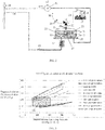
- a degassing module in accordance with the first, second and third aspects of the invention is shown in FIG. 1a .
- the direction of dialysate flow is shown by the arrows.
- the degassing module can be placed in the dialysis circuit preferably at a point between the sorbent cartridge (not shown) and the dialyzer (not shown).
- the degassing module can have a degassing flow loop providing fluid flow that is in parallel to the dialysate flow path.
- the parallel configuration allows the fluid flow through the degassing loop to be independent of the fluid flow rate through the dialyzer such that the fluid flow rate through the degassing loop can be either less than or greater than the dialysate flow rate through the dialyzer.
- the parallel configuration provides control flexibility to adjust the degassing loop flow rate for optimal degassing without requiring the dialysate flow rate through the dialyzer to change.
- the fluid flow through the degassing module can be arranged in series with the dialysate flow to the dialyzer.
- the dialysate can pass a degas restrictor 13 of FIG. 1a .
- the degas restrictor 13 can serve to restrict the flow of fluid through the degassing system.
- the degas restrictor 13 may be a narrow tube or any portion of the flow path that can be narrowed in a controlled fashion.
- restriction can be provided by a portion of the flow path being crushable and having roller portions to create a portion of the flow path having a narrowed inner diameter to thereby restrict flow. Any other mechanical structures known to those of ordinary skill to restrict flow is also contemplated by the first, second and third aspects of the invention.
- the fluid pump 12 fluidly connected to the degas restrictor 13 , pulls fluid through the degas restrictor 13 , creating a reduced pressure in the degassing vessel 11 side of the degas restrictor 13 .
- a vacuum can be created in the degassing vessel 11 side of the degas restrictor 13 .
- a pressure sensor (not shown) can be placed after the degas restrictor 13 to determine the pressure of fluid in the degasser.
- the fluid pump 12 of the present invention can be located downstream of the degassing vessel 11 to allow for improved removal of carbon dioxide.
- the vacuum that can be created by pulling the fluid through the degas restrictor 13 helps to draw dissolved gases, including carbon dioxide, out of solution by reducing the pressure of the fluid below the partial pressure of the dissolved gas in the liquid.
- the degas restrictor 13 need not be a separate component. Instead, the fluid inlet of the degassing vessel 11 can be narrow, and therefore operate as a flow restrictor.
- Vacuum pump 14 on the gas removal pump assembly 15 can be fluidly connected to the degassing vessel 11 by gas removal line 23 and can desirably remove the gases in the low pressure environment inside degassing vessel 11 via mechanical vent valve 20 .
- the fluid enters the degassing vessel 11 , by crossing through the base 25 of the degassing vessel 11 and through degas sprayer 18 .
- the degas sprayer 18 creates a thin spray or mist, which can increase release of dissolved gases from solution by increasing the surface area of liquid in contact with the low pressure atmosphere in the gas space 21 inside degassing vessel 11 to increase the rate at which gas can be liberated from the liquid.
- the fluid can enter the degassing vessel 11 at other locations than the base 25 .
- fluid can enter the degassing vessel 11 at a location on the side of the degassing vessel 11 .
- the degas sprayer 18 can be positioned within the degassing vessel 11 so that the degas sprayer 18 is above the maximum fluid level 26 .
- the degas sprayer 18 is optional and not required to remove carbon dioxide or other gases from the dialysate solution.
- vent valve 10 can be any combination of one or more valves suitable for accomplishing the desired control of gas flow.
- FIG. 1a the pathways open in vent valve 10 are shown in black.
- Vacuum pump 14 on the gas removal pump assembly 15 is attached to the degassing vessel 11 by gas removal line 23 , and provides the force necessary to move gases from the lower pressure degassing vessel 11 out into the atmosphere.
- the vacuum pump 14 exerts a vacuum that is greater than or equal to the vacuum created by the fluid pump 12 pulling fluid through the degas restrictor 13 , which allows the removal of the accumulated gas from the degassing vessel 11 .
- the degassing vessel 11 of the first, second and third aspects of the invention can be operated at a pressure lower than atmospheric pressure due to the presence of vacuum pump 14 .
- the vent valve 10 can allow gas to leave directly into the atmosphere through filter 29 , as represented by arrow 30 .
- the filter 29 is a particle filter that serves to remove particulate matter from air flowing through filter 29 .
- the gases may travel through gas removal line 23 , to the gas removal pump assembly 15 and into the atmosphere as represented by arrow 24 .
- Vent valve 10 can be a three way valve, as shown in FIG. 1a . This can allow air to be removed from the degassing vessel 11 through the gas removal line 23 , and also allow air to be drawn into the degas flow loop when fluid is being drained from the system.
- Overflow float 19 and mechanical vent valve 20 can provide a mechanism for an automatic shutdown, preventing fluid from leaving the degassing vessel 11 through the vent valve 10, but allowing air to be added or removed during filling or draining of the system. If the fluid level in the degassing vessel 11 reaches above a certain point, overflow float 19 can block, either directly or indirectly, the fluid from passing through mechanical vent valve 20 .
- the maximum fluid level in the degassing vessel 11 can be shown by line 26 , while the minimum fluid level can be shown by line 22 .
- a degas float channel 27 can be used to ensure that the overflow float 19 properly engages with the mechanical vent valve 20 .
- the degas float channel 27 can be placed directly underneath the mechanical vent valve 20 so that when the overflow float 19 rises to the top of the degassing vessel 11 , the overflow float 19 will properly cover the mechanical vent valve 20 .
- the float can move an actuator so that the mechanical vent valve 20 is closed.
- the degas float channel 27 can be made with a fluid permeable substance, such as mesh, so that fluid can still move freely through the degassing vessel 11 .
- the function of the degas float channel 27 can be accomplished by a rod through the overflow float 19 wherein the rod is anchored to the degassing vessel 11 .
- the overflow float 19 can be tethered to actuators (not shown). If the overflow float 19 rises, the tethers (not shown) can activate the actuators by pulling on the actuators to either shut off, or modulate the pump rate of, the vacuum pump 14 and fluid pump 12 .
- Lower level sensor 17 and upper level sensor 16 can sense the fluid level in the degassing vessel 11 .
- the fluid level in the degassing vessel 11 can be a function of the vacuum created by fluid pump 12 and vacuum pump 14 working independently or in concert.
- the pump rate of the fluid pump 12 and vacuum pump 14 can be adjusted as necessary to maintain the correct fluid level in the degassing vessel 11 .
- the lower level sensor 17 and upper level sensor 16 can be in electronic communication with a controller (not shown).
- the pump rates of the fluid pump 12 and vacuum pump 14 can be automatically adjusted by the controller to maintain the proper level of fluid in the degassing vessel 11 .
- the pump rates of the fluid pump 12 can be increased, and/or vacuum pump 14 can be reduced. If the fluid level in the degassing vessel 11 is near or below the minimum fluid level 22 , the pump rates of the fluid pump 12 can be reduced and/or vacuum pump 14 can be increased.
- only one sensor is necessary to detect the fluid level in the degassing vessel 11 .
- an ultrasonic sensor or mechanical float can be used to determine the fluid level in the degassing vessel 11 .
- Any other type of fluid level sensor known in the art is contemplated by the first, second and third aspects of the invention.
- Carbon dioxide sensor 28 can determine the amount of carbon dioxide present in the dialysate flow path after dialysate has passed through the degasser.
- the pump rates of fluid pump 12 and vacuum pump 14 can be adjusted as discussed below in response to signals received from the carbon dioxide sensor 28 in order to remove more or less carbon dioxide from the dialysate, and therefore deliver more or less carbon dioxide to the main dialysate flow path.
- the pumps can be adjusted automatically if the level of carbon dioxide detected in the dialysate by carbon dioxide sensor 28 is higher or lower than a pre-set value. Alternatively, the pumps can be adjusted manually in response to output from the carbon dioxide sensor 28 .
- the system can control the degasser to maintain a carbon dioxide level in fluid exiting the degasser between any of 50 and 200 mmHg partial pressure, 50 and 120 mmHg partial pressure, 50 and 80 mmHg partial pressure, 70 and 100 mmHg partial pressure, 80 and 120 mmHg partial pressure, 50 and 200 mmHg partial pressure, or 100 and 200 mmHg partial pressure.
- the carbon dioxide sensor 28 can be placed anywhere in the dialysate flow path, but preferably between the outlet of the degassing flow path and the inlet of the dialyzer (not shown).
- the carbon dioxide sensor 28 can be any components capable of measuring the carbon dioxide in a fluid, directly or indirectly.
- Carbon dioxide sensors and sensors are known in the art. Examples include non-dispersive infrared (NDIR) detectors that detect carbon dioxide concentration in a gas and which are commercially available from a number of manufacturers, for example Gas Sensing Solutions, Glasgow Scotland; colormetric optical detectors that detect carbon dioxide in a liquid by means of a substrate that produce color change when the concentration of carbon dioxide in the liquid changes (PreSens Precision Sensing GmbH, Regensburg Germany); and sensors that utilize Severinghaus electrodes, such as the InPro CO 2 sensor from Mettler Toledo, Leicester England.
- NDIR non-dispersive infrared
- the pumps of the degassing module can be of any type known in the art.
- fluid pump 12 and vacuum pump 14 can be the same type of pump.
- fluid pump 12 and vacuum pump 14 may be different types of pumps.
- the fluid pump 12 and vacuum pump 14 can be a gear pump.
- fluid pump 12 and vacuum pump 14 can be a peristaltic pump, a diaphragm pump or an impeller pump.
- Fluid pump 12 can also have a sensor 31 attached to the fluid pump 12 to monitor performance of the fluid pump 12 and detect wear. The fluid pump 12 must be selected for operating with the pump inlet at a low absolute pressure necessary to efficiently remove carbon dioxide.
- Flow of fluid through the degassing module can be variable. Control over the flow can be provided by fluid pump 12 . Under certain operating conditions the flow rate provided by fluid pump 12 can be less than the flow rate through the main dialysate loop. Fluid pump 12 can be operated so that flow through the degassing module is significantly greater than flow through the main dialysate loop. Fluid pump 12 can be operated to move fluid through the degassing flow loop at a rate of 2-3 times that of the dialysate flow path.
- the fluid pump 12 can be operated to move fluid through the degassing flow loop at a rate between 1-6 times that of the dialysate flow path, 1-2 times that of the dialysate flow path, 3-4 times that of the dialysate flow path, 4-5 times that of the dialysate flow path or 5-6 times that of the dialysate flow path.
- the flow through the degassing module can be controlled automatically by a controller in communication with the fluid pump 12 depending on the amount of carbon dioxide that is to be removed.
- the invention can utilize the vacuum pump 14 to remove gas from the degassing vessel 11 to the atmosphere when the degassing vessel 11 is operated under vacuum.
- Known degassing systems pump fluid into a vessel at ambient pressure where bubbles are allowed to escape.
- providing a second pump or any one of the specific pump configurations described in the first, second and third aspects of the invention to keep a degassing vessel 11 under vacuum can unexpectedly result in higher amount of gases such as carbon dioxide being removed.
- the passage from the degassing vessel 11 to vent valve 10 can be covered by a hydrophobic membrane (not shown).
- a hydrophobic membrane will prevent fluid from escaping the degassing vessel 11 through mechanical vent valve 20 . This, in turn, protects the vacuum pump 14 from being damaged by liquid and prevents undesired loss of liquid from the system while still enabling gas to be removed.
- the hydrophobic membrane can be positioned in any appropriate location to guard against inadvertent fluid flow to the vacuum pump 14 , and thereby prevent fluid damage.
- a hydrophobic membrane is Polytetrafluoroethylene, or PTFE.
- the hydrophobic membrane can be made of any material.
- air can be drawn into the system in order to drain out the fluid in the fluid pathways of the system.
- Air can be added to the system through vent valve 10 as shown in FIG. 1b .
- vent valve 10 the pathways of vent valve 10 that are open are shown in black.
- Air can be passed through filter 29 , which can remove any particulate matter and microorganisms before the air enters the dialysis system, and into the degassing vessel 11 through vent valve 10 .
- Fluid pump 12 can force this air into the dialysate flow path (not shown).
- nucleation chamber 32 contains a high surface area medium, such as fiber mesh, filter or beads, or other configuration known to those of ordinary skill.
- the high surface area provides sites where gas bubbles can nucleate and collect to form larger bubbles, making removal of the gases more efficient.
- the bubbles rise through the fluid as the fluid enters the degassing vessel 11 and collect at the gas space 21 , similar to what is shown in FIG. 1a .
- the nucleation chamber 32 can be placed inside of the degassing vessel 11 , so that fluid moves through the nucleation chamber 32 as the fluid moves through the degassing vessel 11 and gas bubbles, once freed from the high surface area medium in the nucleation chamber 32 , are immediately collected in the gas space 21 of the degassing vessel 11 .
- both a nucleation chamber and a degas sprayer can be used. Such an arrangement can further help gas to be released from solution to collect at the top of the degassing vessel 11 .
- only one of a degas sprayer or nucleation chamber can be used.
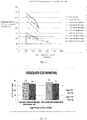
- FIG. 3 is a graph showing the CO 2 outlet concentration, stated as partial pressures, at the outlet of the degasser as a function of the absolute pressure in the degassing vessel 11 for a variety of CO 2 inlet concentrations, stated as partial pressures.
- the block labeled 130 is a desired operating CO 2 concentration, expressed as a partial pressure, of between 50 and 120 mmHg.
- the absolute pressure in the degassing vessel 11 shown in FIG.'s 1 and 2 is a function of the fluid pressure, determined by the pump rate of the fluid pump 12 , and the vacuum pressure, determined by the pump rate of the vacuum pump 14 . By controlling the two pumps, the pressure in the degassing vessel 11 can be accurately controlled. As shown in FIG.
- the degasser of the first, second and third aspects of the invention is capable of removing enough CO 2 to maintain a carbon dioxide level at the outlet of the degasser between 50 and 120 mmHg for a large range of inlet CO 2 concentrations and dialysate flow rates.
- a degassing vessel pressure of between 60 and 200 mmHg absolute pressure can allow for optimal CO 2 removal across a range of inlet CO 2 concentrations and dialysate flow rates.
- degassing vessel pressure of between any of 40 mmHg and 2000 mmHg, 40 mmHg and 300 mmHg, 40 mmHg and 100 mmHg, 80 mmHg and 150 mmHg, 120 mmHg and 250 mmHg or 200 mmHg and 300 mmHg, can allow for optimal CO 2 removal.
- the desired outlet concentration of CO 2 can be obtained for the entire range of inlet CO 2 concentrations and flow rates tested by adjusting the pump rates of the two pumps to arrive at the necessary degassing vessel pressure.
- the vacuum pump 14 may be shut off if the CO 2 concentration is below the lower limit. In such cases, the pressure in the degassing vessel 11 will be the same as the pressure of the dialysate fluid, which can be up to 2000 mmHg.
- FIG. 4 provides comparative data for known systems operating at ambient pressures showing an outlet CO 2 concentration, stated as partial pressure, in a system that does not use a vacuum pump as in the first, second and third aspects of the invention. Because no vacuum pump is used in known systems, and the known degassing vessels are not able to operate at low absolute pressures, the amount of CO 2 removed is limited by the need to maintain sufficient pressure in the degassing vessel to vent the released gas. As can be seen in FIG. 4 , a degasser without a degassing vessel under vacuum can only operate to obtain an outlet CO 2 concentration of between 50 and 120 mmHg when the inlet concentration of CO 2 is around 200 mmHg or below.
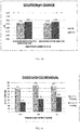
- FIG. 5a shows the amount of CO 2 removed from dialysate without operating the degas vessel under vacuum by means of a fluid pump placed downstream of the degas vessel.
- FIG. 5b shows the change in pH in the same system.
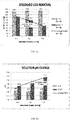
- FIG.'s 6a and 6b show the amount of CO 2 removed, and the effect on pH, in the same system with a fluid pump added downstream of a degassing vessel, shown for a dialysate flow path flow rate from 150 mL/min to 500 mL/min.
- the location of the degasser upstream or downstream with respect to a microbial filter does not alter the amount of CO 2 removed.
- the described configuration with degasser upstream of the microbial filter can provide for the removal of gas from the dialysate prior to reaching the microbial filter, and thereby advantageously reduce gas accumulation in the microbial filter.
- FIG. 7 shows the amount of CO 2 removed as a function of the rate of flow through the degassing flow loop.
- the dialysate flow rate was 600 mL/min.
- the amount of CO2 removed can increase as the flow rate through the degassing flow loop increases.
- FIG.'s 8a and 8b show the amount of CO 2 removed, and the effect on pH, as a function of the absolute pressure in the degassing flow loop.
- the dialysate flow rate and degassing flow rate were held constant at 300 mL/min.
- the degassing flow loop pressure can have a linear relationship with outlet CO 2 concentration.
- the pressure in the degassing flow loop, and in the degas vessel in particular can be affected by the action of the fluid pump pulling fluid through the degas flow restrictor and the vacuum pump acting to remove the released gases from the degassing vessel.
- the action of the vacuum pump allows released gases to be vented from the degas vessel when the degas vessel is operated at pressures substantially below ambient. This, in turn, can allow for the removal of additional CO 2 .
- the outlet CO 2 concentration can be dependent on the inlet CO 2 concentration, the fluid pressures within the degassing flow loop, and the rates of flow through dialysate flow path and the degassing flow loop.
- the dialysate flow path and the degassing flow loop can operate in parallel or in series.
- FIG.'s 9a and 9b show the amount of CO 2 removed, and the effect on pH with differing inlet CO 2 concentrations.
- the flow rates through the dialysate flow path and degassing flow loop were held at 300 mL/min and the degassing loop fluid pressure was held constant at 630 mmHg vacuum.
- the outlet CO 2 concentration is not significantly affected by large changes in the inlet CO 2 concentration. In all cases, the outlet CO 2 concentration was reduced to between 75-85 mmHg, despite the variations in inlet CO 2 concentrations.
- FIG. 10 shows a flow diagram, explaining one non-limiting embodiment of the operation of the vacuum pump and fluid pump of the first, second and third aspects of the invention in relation to the data received from the CO 2 sensor.
- both the vacuum pump and the liquid pump may be operated simultaneously.
- Data received from the CO 2 sensor 111 is transmitted to controller 112 . If the CO 2 concentration detected by the CO 2 sensor 111 is within the desired range in step 117 , the controller 112 can continue operating the pumps in the same manner in step 113 . If the CO 2 concentration detected by the CO 2 sensor 111 is too low 118 , the controller 112 can do either of two options.
- the controller 112 can cause the fluid pump to decrease the flow rate in the degassing flow loop in step 114 , causing the absolute pressure of the fluid in the degassing loop to increase and thereby reduce the amount of CO 2 removed by the degasser as shown in FIG.'s 3 and 7.
- Step 114 can alternatively involve that the fluid pump is shut off completely, thereby stopping the removal of CO 2 from the dialysate.
- the controller 112 can decrease the pump rate of, or shut off completely, the vacuum pump in step 115 .
- both steps 114 and step 115 can be carried out in response to a signal showing the CO 2 level to be too low.
- the controller 112 can cause the fluid pump to increase the flow rate through the degassing flow loop in step 116 , and thereby increase the amount of CO 2 removed by the degasser as shown in FIG.'s 3 and 7.
- the controller 112 can increase the pump rate of the vacuum pump in step 110 , to remove the increased amount of gas being released from solution when the flow rate through the fluid pump is increased 116 which also enables the proper liquid level to be maintained in the degas vessel when the pressure within the degas vessel is reduced and causes the removal of more CO 2 .
- Steps 116 and 110 can both be carried out in response to a signal showing that the CO 2 concentration is too high. Regardless of the action taken in response to the data received by the CO 2 sensor 111 , the CO 2 concentration in the dialysate can be continuously monitored, as represented by arrow 120 , and further adjustments to the rate of the fluid pump can be made as the CO 2 concentration in the dialysate changes.
- the vacuum pump may run continuously with the exception of step 115 , to draw out the CO 2 from the degas vessel as the CO 2 accumulates.
- FIG. 11 shows an alternative embodiment to that shown in FIG. 10 , where the vacuum pump and fluid pump are run alternately.
- the fluid pump can be operated to pull fluid through the degassing flow loop. Data is sent from the CO 2 sensor 121 to the controller 122 showing the CO 2 concentration in the dialysate. While the CO 2 concentration in the dialysate is above the desired range 123 , the fluid pump can be operated as explained above to remove CO 2 from the dialysate. The CO 2 concentration can be continuously monitored as the fluid pump operates, as shown by arrow 128 . Once the CO 2 concentration has decreased into the desired range 127 , the controller 112 can cause the fluid pump to shut off 124 .
- the vacuum pump can be turned on 125 to remove the gases that have collected in the degas vessel. While the fluid pump is shut down, the CO 2 concentration in the dialysate will increase, due to the fact that dialysate is not being directed through the degasser, and will be monitored as shown by arrow 129 . When the CO 2 concentration has risen 126 to a desired range 123 , the fluid pump can again be operated and the vacuum pump shut off.
- the controller can set initial pump rates for both the vacuum pump and fluid pump based on the initial carbon dioxide concentration in the dialysate. For example, if the initial carbon dioxide concentration in the dialysate is 415 mmHg partial pressure, the fluid pump and vacuum pump may be set to maintain an absolute pressure in the degas vessel of 100 mmHg. As shown in FIG. 3 , this would allow for an outlet CO 2 concentration of between 50-120 mmHg partial pressure. If, during operation, the concentration of carbon dioxide were to become reduced to 117 mmHg partial pressure, the controller can alter the pump rates of the fluid pump and/or vacuum pump as described above to maintain an absolute pressure in the degas vessel of 190 mmHg. As shown in FIG. 3 , this would maintain a carbon dioxide level above 50 mmHg partial pressure.
- the degasser can be located in a fluid flow path in a position directly after the sorbent cartridge.
- the position of the degasser is not limited to any one position.
- the degassing module may be located in other positions between the sorbent cartridge and the dialyzer.
- valves and pumps may be operated by a programmable controller or computer system that can be programmed to regulate flow through the pumps and valves and into and out of the reservoirs.
- a rotometer or turbine with optical sensor, photocell, magnetic sensor, or other flow sensing apparatus may detect the flow of fluid through any two points in the degassing system.
- an optical fluid flow device can be provided for measuring flow wherein the device includes an optical fluid pressure measuring device having sensors positioned in any one of the flow paths between the reservoirs, in the connectors, or in the valves or valve assemblies.
- a flow sensing apparatus can have a flow-responsive element projecting into a fluid flow path, and a position sensor associated with the element which detects a change in position of the flow-responsive element in response to the fluid flow.
- the flow-responsive element can be made of a wide variety of materials having the desired properties known to those of ordinary skill in the art.
- FIG. 8a demonstrates the relationship between the pressure in the degasser and the concentration of dissolved carbon dioxide in the fluid that has passed through the degasser
- FIG. 9a which demonstrates that the carbon dioxide concentration in the fluid that has passed through the degasser remained constant in a tight range when the carbon dioxide concentration in the fluid entering the degasser was more than doubled.
- the operating pressure of the degasser can be used to control the concentration of carbon dioxide in the fluid exiting the degasser.
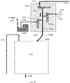
- Blood enters dialyzer 50 as shown by arrow 51 and exits the dialyzer 50 as shown by arrow 52 .
- Dialysate recirculating in dialysate flow path 55 enters the dialyzer 50 at connector 54 and exits the dialyzer 50 at connector 53 with urea that has been removed from the blood.
- the dialysate is pumped by dialysate pump 49 through valve 47 and through sorbent cartridge 48 where the urea is removed from the dialysate by an exchange process that results in carbon dioxide being added to the dialysate as the dialysate flows through sorbent cartridge 48 .
- the dialysate exiting the sorbent cartridge 48 is drawn into the degassing system by action of fluid pump 12 through inlet line 65 .
- the dialysate passes through degas flow restrictor 67 where the fluid pressure is reduced by the pressure drop that occurs as the dialysate flows through the degas flow restrictor 67 .
- the dialysate enters degassing vessel 68 and passes through optional degas sprayer 18 that acts to increase the surface area of the liquid and thereby increase the rate at which the dissolved carbon dioxide is released from the fluid to the gas space 21 at the top of the degassing vessel 68 .
- Carbon dioxide gas is collected in the gas space 21 and the degassed fluid is collected in the liquid space of degassing vessel 11 .
- Gas bubbles in the liquid rise to be collected in gas space 21 and the liquid exits the base 25 of degassing vessel 68 and passes through fluid pump 12 and is returned to the recirculating dialysate flow path 55 through return line 66 .
- the released gas can exit the degassing vessel 68 at outlet connector 33 and pass through vent line 63 to vent control valve 40 through outflow line 42 to outflow valve 41.
- outflow valve 41 directs the flow path to gas removal pump assembly 15 through gas removal line 64 .
- Vacuum pump 14 pulls the gas from the low pressure environment of degassing vessel 68 and pumps the gas out through degassing outlet line 43 .
- Degassing outlet line 43 can optionally be connected to drain line 46 . Connecting degassing outlet line 43 to drain line 46 muffles the noise of the vacuum pump 14 and directs any condensed water vapor to reservoir 60 through drain line 46 and connector 59. The removed gas flows out of reservoir 60 through vent 58 .
- Level sensor 61 can measure the liquid level 26 in degassing vessel 68 .
- Level sensor 61 can be an ultrasonic sensor.
- Level sensor 61 can be an array of reed switches that detect the height of a magnetic float.
- Level sensor 61 can include a linear array of hall-effect sensors.
- the rate of vacuum pump 14 can be increased to increase the liquid level 26 when level sensor 61 detects that the liquid level 26 is below a predetermined level.
- the rate of vacuum pump 14 can be reduced when the level sensor 61 detects that the liquid level 26 is above a predetermined level.
- the vacuum pump 14 can act as a check valve preventing air or liquid from returning to the degasser through degassing outlet line 43 , but can allow gas outflow from the degasser through degassing outlet line 43 including when the gas removal pump is deenergized or turned off.
- Air can be rapidly evacuated from the dialysate flow path 55 through outlet connector 33 , vent line 63 , vent control valve 40 , degassing outflow valve 41 and gas removal pump assembly 15 and degassing outlet line 43 during priming operations when the liquid entering the dialysate flow path 55 causes the pressure to increase, forcing the air in the gas space 21 of degassing vessel 68 through outlet connector 33 when the pressure in gas space 21 is greater than atmospheric pressure.
- Vent control valve 40 can be switched to filter 29 and air can be drawn into the degassing vessel 68 as depicted by arrow 45 when liquid is being drained from the recirculating dialysate flow path 55 through drain valve 47 through drain line 46 and connector 59 to reservoir 60 .
- Filter 29 can have a pore size that excludes microbes and particulate to prevent contamination of the system when air is drawn in.
- degassing vessel 68 can be completely filled with liquid and liquid can be passed out through outlet connector 33 through vent line 63 , vent control valve 40 , and degassing outflow valve 41 to recirculation line 44 .
- This flow path enables cleaning and disinfection solutions, including the non-limiting examples of hot water, heated citric acid solution, and bleach to be recirculate through the outlet connector 33 , vent line 63 , and vent control valve 40 .
- microbiological contamination and biofilms can be minimize in the degassing vessel 68 and also in the flow path used to bring air into the system when liquid is being drained from the system.
- the flow restrictor 67 can have a fixed restriction, or can comprise a pressure regulator that changes the amount of flow restriction as the pumping rate of fluid pump 12 changes, such that a predetermined pressure is maintained in the dialysate exiting the restrictor across a range of operating rates of fluid pump 12 .
- the amount of restriction caused by flow restrictor 67 can be controlled to achieve a predetermined pressure in the fluid passing through the degasser.
- Pressure sensor 62 can measure the fluid pressure in the degassing system. Pressure sensor 62 can be located on the degassing vessel 11 and can measure the pressure in the liquid or the gas. Pressure sensor 62 can be located at any point in the degasser between the flow restrictor 67 and fluid pump 12 . The pressure measurement obtained from pressure sensor 62 can be used to adjust the restriction of flow restrictor 67 to obtain a predetermined pressure in the degassing system.
- the rate of fluid pump 12 can be controlled to achieve a predetermined fluid pressure in the degassing system. The rate of fluid pump 12 can be increased to reduce the fluid pressure in the degasser if the fluid pressure measured by pressure sensor 62 is above the predetermined pressure. The rate of fluid pump 12 can be decreased to increase the fluid pressure in the degasser if the fluid pressure measured by pressure sensor 62 is below the predetermined fluid pressure.
- an alternative control scheme can be employed in any embodiment of the invention, wherein the pressure in the gas space 21 can be controlled by vacuum pump 14.
- the pressure in the gas space 21 can be measured by pressure sensor 62 and a controller can adjust the rate of vacuum pump 14 to keep the pressure in gas space 21 at a predetermined level.
- the rate of fluid pump 12 can be increased to decrease the liquid level 26 in degassing vessel 68 or the rate of fluid pump 12 can be decreased to increase the liquid level 26 in degassing vessel 68 .
- liquid level measurements from level sensor 61 can be used to determine whether the rate of fluid pump 12 should be increased or decreased.
- the rate of fluid pump 12 can be maintained at a constant rate while increasing the amount of flow restriction caused by flow restrictor 67 to decrease the liquid level 26 in degassing vessel 68 or decreasing the amount of flow restriction caused by flow restrictor 67 to increase liquid level 26 in degassing vessel 68 .
- FIG. 13 is an alternative degassing system for use in dialysis that reduces foaming.
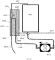
- dialysate is pumped from a dialyzer (not shown) through dialysate line 201 .
- Dialysate can enter degassing vessel 206 through a fluid inlet, shown as degas sprayer 207 , which enters the degassing vessel 206 through a top portion 208 of degassing vessel 206 .
- a fluid inlet can be located at the bottom of the degassing vessel 206 or at any other location relative to the degassing vessel 206 .
- An internal conduit or passageway can convey the fluid to the degas sprayer 207 at the top of the degassing vessel 206 .
- the top portion 208 of the degassing vessel 206 can also be referred to as the "headspace.”
- the degas sprayer 207 sprays dialysate downwardly into the degassing vessel 206 .
- Foaming can be controlled by spraying downwardly onto a liquid pool in the degassing vessel 206 .
- the downward spray cuts the upward growth of foam, as described.
- the degassing vessel 206 can be separated into a spray chamber 210 and a float chamber 209 by separator 229 .
- a channel (not shown) can be included in separator 229 to allow fluid to move from the spray chamber 210 to the float chamber 209 to provide an accurate reading on fluid level.
- the float chamber 209 can include one or more level sensors. As illustrated in FIG. 13 , the level sensor can include a magnetic float 231 on guide 230 . A linear array of Hall effect sensors (not shown) can be included to measure the level of the float 231 and determine the fluid level in the degassing vessel 206 .
- the float 231 can be magnetic, and a linear array of Hall effect sensors can measure the height of the float directly.
- a magnet can be affixed to the float 231.
- the level sensors can include a capacitive or ultrasonic sensor to measure the height of the liquid directly.
- An ultrasonic sensor emits an ultrasonic wave and measures the distance to the liquid based on the time between emission of the wave and detection of the wave reflected back by the liquid.
- a capacitive sensor measures distance to the liquid by measuring changes in capacitance as the liquid moves closer to or further away from the sensor.
- the height of the fluid in the degassing vessel 206 can be controlled to within a predetermined range to ensure that the liquid level is below the degas sprayer 207 , ensuring that the degas sprayer 207 nozzle is exposed and that atomized fluid is exposed to the low pressure in the top portion 208 of the degassing vessel 206 .
- the fluid level should also remain low enough that loss of liquid through the gas outlet line 217 is prevented, and high enough such that undissolved gas bubbles in the liquid are separated and captured.
- Fluid can be sprayed into the spray chamber 210 of the degassing vessel 206 .
- Gas can be removed from the fluid through a gas outlet fluidly connected to gas outlet line 217 .
- a gage pressure sensor 216 in the gas outlet can measure the pressure inside the degassing vessel 206 .
- Gas bubble nucleation can occur as the fluid is sprayed into the spray chamber 210 .
- the gas bubbles rise through the liquid and are captured and collected in a headspace of the degassing vessel 206 . Bubble capture can be ensured when the downward velocity of the liquid in the degassing vessel 206 is less than the rise velocity of the bubbles through the liquid.
- the degas sprayer 207 atomizes the fluid and creates a high surface area to volume ratio between the liquid droplets and gas in the degas vessel headspace.
- vacuum pump 218 is used to lower the pressure in the degassing vessel 206 , and is fluidly connected to gas outlet line 217 by valve 219 and vacuum line 220 and can be controlled by a controller to maintain a desired pressure within the degassing vessel 206 .
- the vacuum pump 218 is continuously run at a high rate, and the controller can pulse width modulate valve 219 to control the pressure in the degassing vessel 206 to a desired target.
- the removed gases are expelled through gas line 221 , which can be vented to the air, or alternatively, connected to a waste reservoir.
- Degassed fluid can exit the degassing vessel 206 through a liquid outlet 212 in a base 211 of the degassing vessel 206 , fluidly connected to fluid line 204 .
- the liquid outlet 212 is located at a lower elevation in the degassing vessel 206 than the gas outlet at gas outlet line 217 .
- Fluid can be pumped by fluid pump 213 , through fluid line 205 , and back to dialysate line 201 at junction 227 .
- the fluid pump 213 provides the force necessary to move fluid from the low pressure degassing vessel 206 to the higher pressure in dialysate line 201 .
- Fluid can be pumped from the degassing flow path at junction 232 into the main dialysate flow path through fluid line 203 by dialysate pump 214 into dialysate line 202 .
- the flow rate of fluid through the main dialysate flow path can be controlled by dialysate pump 214 , and optionally one or more additional dialysate pumps. As such, the flow rate of fluid through the degassing flow loop can be controlled independently of the flow rate of fluid in the main dialysate flow path.
- fluid pump 213 By operating fluid pump 213 at a higher pump rate than dialysate pump 214 , fluid can be recirculated through the degassing vessel 206 multiple times prior to returning to the main dialysate flow path, allowing additional control over the amount of gas removed.
- the rate of liquid recirculation through the degassing vessel 206 can help to ensure sufficient exposure to the headspace of the degassing vessel 206 so that dissolved gases in the liquid come into equilibrium with the gas partial pressures in the degassing vessel 206 .
- the flow rate of fluid through the degassing flow loop can be set to about two times the dialysate flow rate.
- the fluid pump 213 and dialysate pump 214 can be controlled by a controller (not shown) to operate at the desired ratio.
- a vent valve 223 fluidly connected to the gas outlet line 217 can be controlled to allow air into the degassing vessel 206 when the degassing vessel 206 is drained.
- Filter 224 prevents contamination of the degassing vessel 206 , and can have a pore size that excludes microbes and particulate matter to prevent contamination of the system when air is drawn in through vent valve 223 .
- degassing vessel 206 can be completely filled with liquid and liquid can be passed out through gas outlet line 217 through valve 225 and fluid line 226 , to dialysate line 202 at junction 228 .
- the flow path enables cleaning and disinfection solutions, including the non-limiting examples of hot water, heated citric acid solution, and bleach to be recirculate through all of the lines of the degassing system. In this manner, microbiological contamination and biofilms can be minimized in the degassing vessel 206 and also in the flow path used to bring air into the system when liquid is being drained from the system.
- a temperature sensor (not shown) can be included to monitor the temperature during disinfection, and to measure the temperature of dialysate prior to reaching a heater (not shown) in the dialysate flow path.
- An ambient pressure sensor 222 can measure the atmospheric pressure outside of the degassing system, and is used in control of gas removal from the fluid.
- the degassing system should control carbon dioxide removal to maintain a carbon dioxide level within a desired range.
- the desired range can be between 40mmHg - 150mmHg pCO 2 .
- the concentration of the dissolved gases in the dialysate exiting the degassing vessel 206 are proportional to the absolute partial pressures of the gas in the top portion 208 , and as such, the environmental pressure as measured by ambient pressure sensor 222 can be used to control the gas pressure within the degassing vessel 206 .
- Ambient pressure sensor 222 measures the absolute pressure of the environment outside of the degassing vessel 206.
- Gage pressure sensor 216 measures a gage pressure referenced to the ambient pressure sensor 222 .
- the pressure as measured by ambient pressure sensor 222 plus the gage pressure measured by gage pressure sensor 216 provides the absolute pressure in the top portion 208 of the degassing vessel 206 .
- the gage pressure sensor 216 can be replaced by an absolute pressure sensor, and the ambient pressure sensor 222 is not required.
- the dialysate flow rate also controls the amount of gas removed.
- the dialysate flow rate through the degassing flow loop can be between 100mL/min to 800mL/min.
- the dialysate flow path can include a heater (not shown) to heat the dialysate to a desired temperature prior to reaching the dialyzer.
- the degassing flow loop can be positioned either upstream or downstream of the heater.
- the degassing system should be able to operate over the entire possible range of dialysate temperatures.
- the dialysate temperature in the degassing flow loop should be between about 35°C to about 39.5°C.
- the possible temperature range of dialysate in the dialysate flow path can be larger, including from between about 10°C to about 45°C.
- the amount of gas removed by the degassing system is a function of the absolute headspace pressure in the degassing vessel 206 , as well as the degassing flow loop flow rate.
- the headspace pressure of the degassing vessel 206 an estimated degasser inlet carbon dioxide concentration is used, as described.
- the size and flow rate through the degassing flow loop and degas sprayer 207 is sufficient to ensure that dissolved gases in the liquid exiting the degassing vessel 206 through fluid line 204 are in approximate equilibrium with the gas partial pressure in the top portion 208 , or headspace, of the degassing vessel 206.
- the carbon dioxide pressure can be controlled by controlling the absolute headspace pressure.
- the carbon dioxide pressure can be controlled across a very wide range of inlet carbon dioxide pressures.
- the headspace pressure can be controlled to a predetermined target, irrespective of the estimated carbon dioxide concentration in the liquid entering the degassing vessel through dialysate line 201.
- the vacuum pump 218 is operated by the controller at a fixed rate.
- the absolute headspace pressure in the degassing vessel 206 is equal to the degassing vessel pressure as measured by gage pressure sensor 216 plus the atmospheric pressure as measured by absolute ambient pressure sensor 222 .
- Valves 219 and 223 can be selectively operated by the controller to allow the vacuum pump 218 to remove air from the degassing vessel 206 or to allow air to flow into degassing vessel 206 , thereby controlling the headspace pressure to the headspace pressure set point.
- the estimated degasser inlet carbon dioxide concentration can vary as a profile during a dialysis session, and as such, the headspace pressure set point can also vary during treatment.
- the degassing flow loop flow rate can be controlled by using a fixed pressure change to achieve a desired flow rate. The pressure change can be measured by the difference between the incoming fluid pressure as measured by pressure sensor 215 and the pressure within the degassing vessel 206 measured by gage pressure sensor 216.
- a pressure change set point can be set, and the fluid pressure at pressure sensor 215 varied by changing the fluid pump 213 rate until the pressure change set point is reached.
- the relationship between the pressure change and the flow rate can be empirically determined. Alternatively, the relationship can be calculated using an algorithm.
- the degassing flow loop flow rate should be set at a rate sufficient to ensure the dialysate comes into approximate equilibrium with the gas pressures in the degassing vessel 206 , but low enough to avoid over degassing, erratic level behavior, or excess foam generation. In certain embodiments, the degassing flow loop flow rate can be set between 750 and 800 mL/min.
- a protective system can be used.
- the protective system can receive the dialysate flow rate from a flow sensor (not shown) in the dialysate flow path and determine the change in pressure set point to operate the degassing flow loop flow rate at a set ratio to the dialysate flow path flow rate.
- the protective system can determine an expected operating rate (RPM) of the fluid pump 213 corresponding to the pressure change set point, and calculate a running average operating rate for fluid pump 213 .
- the protective system can generate an alert if the running average of RPM for fluid pump 213 is outside of a predetermined range of the expected value.
- the predetermined range can be ⁇ 10% of the expected value.
- the protective system can also monitor the pressure in the headspace of the degassing vessel 206.
- the protective system can measure the ambient pressure with ambient pressure sensor 222 and the pressure inside the degassing vessel 206 with gage pressure sensor 216 to calculate the absolute pressure within the degassing vessel 206 and can calculate a running average of the absolute pressure.
- the running average of absolute pressure can be compared to a predetermined limit, and an alert generated if the absolute pressure is outside of the predetermined limit.
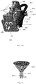
- FIG. 14 shows a cross-section of a degassing vessel 301 for use in dialysis.
- the degassing vessel 301 can be divided into a spray chamber 302 and a float chamber 303 .
- the float chamber 303 can contain one or more level sensors in communication with a controller.
- the level sensors can be a magnetic float and a linear array of Hall effect sensors (not shown).
- Fluid enters the degassing vessel 301 through a fluid inlet 304 fluidly connected to a degas sprayer 305 .
- the degas sprayer 305 sprays the fluid into the spray chamber 302 .
- One or more channels (not shown) connect the spray chamber 302 to the float chamber 303 equilibrating the fluid level in each chamber.
- Degassed fluid exits the degassing vessel 301 through opening 306 fluidly connected to liquid outlet 307 .
- the liquid outlet 307 is located in a bottom portion of the spray chamber 302 .
- fluid may enter or exit the float chamber 303 only when the fluid level in the degassing vessel 301 is changing, reducing turbulence in the float chamber 303 and reducing the amount of gas bubbles that come out of solution in the float chamber 303 .
- a more accurate and stable detection of fluid level may be achieved.
- the liquid outlet 307 can be positioned in a bottom portion of the float chamber 303 or between the spray chamber 302 and float chamber 303 . Further, placing the liquid outlet 307 at the bottom portion of the spray chamber 302 increases the recirculating flow rate of fluid in the degassing flow loop, which beneficially increases the gas removal rate.
- Gases can be removed from the degassing vessel 301 through gas outlet 308 , which can be fluidly connected to a vacuum pump (not shown) by one or more valves.
- the gas outlet 308 is positioned at a top portion of the degassing vessel 301 between the spray chamber 302 and the float chamber 303 . Placing the gas outlet 308 between the spray chamber 302 and float chamber 303 allows symmetrical gas removal from both chambers while preserving the filling, draining, and disinfection capabilities of the degassing vessel 301 .
- Holes 309 can be included for securing a circuit board including the linear array of Hall effect sensors to detect the level of the float (not shown) and therefore the liquid level in the degassing vessel 301 .
- the spray chamber 302 can have a substantially conical shape, as opposed to a tubular or other shape.
- the conical shape of the spray chamber 302 can cause spraying fluid to contact the walls of the spray chamber 302 at a shallower angle than if the spray chamber 302 has a tubular shape.
- the shallow angle of spray contacting the walls of the spray chamber 302 may result in less turbulence, reducing foaming of the fluid in the degassing vessel 301 and allowing more accurate measurements of the fluid level.
- the conical film of spray existing the nozzle of degas sprayer 305 and impinging on the cone wall creates a foam cutting barrier above which the foam cannot grow.
- Reducing foaming also reduces gas flow restrictions out of the degassing vessel 301 , allowing for a higher gas removal volume and faster headspace recovery.
- foam exits thru gas outlet 308 the foam can impede the gas flow thru the vacuum pump, causing an abrupt increase in headspace pressure. Preventing the foam from rising to gas outlet 308 prevents the gas flow from the vacuum pump from being restricted by the foam and the headspace can more quickly recover from any perturbation.
- the spray chamber 302 can be any length and diameter sufficient to effectively capture bubbles in the fluid sprayed into the spray chamber 302 .
- the spray chamber 302 can have a diameter of about 75 mm and a height of about 10 cm, which gives a balance of degassing capacity and foam control without excessive size or fluid volume.
- the diameter can be between about 50 mm to about 100 mm, including between 50 mm and 75 mm, between 50 mm and 60 mm, between 60 mm and 100 mm, or between 75 mm and 100 mm.
- the height of the spray chamber 302 can be between about 60 mm and about 200 mm, including between 60 mm and 100 mm, between 60 mm and 75 mm, between 70 mm and 100 mm, between 90 mm and 125 mm, between 100 mm and 150 mm, between 125 mm and 200 mm or between 150 mm and 200 mm.
- a larger length and diameter of the spray chamber 302 can further reduce foaming by creating a better transition zone when fluid is sprayed into the spray chamber 302 .
- a larger diameter spray chamber 302 also increases the surface area of the fluid and causes the sprayed liquid to have a greater contact time with the headspace, allowing more efficient gas removal.
- the degas sprayer 305 can be constructed to create an even cone shaped spray, rather than a more coarse "fountain like" spray, which can further reduce foaming in the spray chamber 302 .
- the sprayer can reduce foaming by acting as a cap to control the foam.
- a finer spray cone, rather than a fountain type spray, can also increase atomization of the fluid and accelerate gas removal, increasing the efficiency of the degasser.
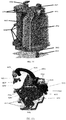
- FIG. 15a is a top view of a degassing vessel 401 for use in dialysis and FIG. 15b is a side view of the degassing vessel 401 .
- the degassing vessel 401 can include a spray chamber 407 and a float chamber 408 .
- One or more level sensors (not shown) can be included in float chamber 408 to measure a fluid level in the degassing vessel 401 .
- a manifold 410 can house fluid flow paths in a degassing flow loop. Fluid enters the manifold 410 from a dialysate flow path (not shown) through inlet 411 .
- the fluid flows through fluid line 403 and fluid inlet 404 in a top portion 402 of the degassing vessel 401 .
- the fluid inlet 404 can be fluidly connected to a degas sprayer (not shown in FIG.'s 15a-b) in an interior of the spray chamber 407 . Gases are removed via gas outlet 409 , as illustrated in FIG. 15a , which can be fluidly connected to a vacuum pump (not shown).
- a vacuum pump not shown
- Fluid lines can connect the liquid outlet 416 to a fluid pump (not shown), and back to the manifold 410 through a second inlet 412 to recirculate the fluid in the degassing flow loop. Fluid can be directed back to a dialysate flow path, parallel to the degassing flow loop, through outlet 417 in manifold 410 .
- Gage pressure sensor 405 can measure the pressure in the headspace of the degassing vessel 401 .
- Pressure sensor 413 can measure the pressure of the incoming liquid, which may be used to control the pump rates of the fluid pumps.
- Mounting bases 414 , 415 , and 418 can be included to attach the circuit board including the linear array of Hall effect sensors to detect the float in the float chamber 408 .
- FIG. 16 illustrates a non-limiting embodiment of a spray nozzle 501 for use in a degassing system.
- the spray nozzle 501 includes an internal conduit 502 through which fluid flows.
- the internal conduit 502 can include one or more swirl inducing sets 503 , which force the fluid into a vortex motion within the internal conduit 502 , breaking the fluid apart.
- fluid exiting the spray nozzle 501 produces a full cone 504 that evenly distributes a spray pattern.
- the high surface area to volume ratio in the cone 504 allows gas to rapidly move from solution into equilibrium with the low gas pressure inside the degassing vessel.
- the spray nozzle 501 used with a degasser influences the relationship between the flow rate and the pressure change from the fluid inlet to the inside of the degassing vessel.
- the relationship between the flow rate and pressure change can be used to control the degassing flow loop flow rate, and the pressure change set point can be adjusted based on the spray nozzle used.
- the spray is a dense conical film that smashes foam bubbles as the foam head grows upward, thus limiting the upward growth of the foam to the surface height defined by the spray cone.
- the degassing system should be able to control the carbon dioxide concentration in the dialysate flow path at the dialyzer inlet to a specified range, which in certain embodiments can be between 40mmHg - 150mmHg pCO 2 .
- the expected range of CO 2 concentrations at the inlet to the degassing flow loop can vary from between 85 to 650 mmHg pCO 2 .
- FIG.'s 17a and 17b illustrate the expected pCO 2 minima and maxima, respectively. A summary of the simulations are shown in Table 1.
- the 99 th percentile for the minimum range for carbon dioxide concentration in dialysate exiting a sorbent cartridge, or the minimum range for carbon dioxide concentration in dialysate entering the degassing system is 130 mmHg.
- the 99.99 th percentile for the minimum range for carbon dioxide concentration is 85 mmHg, even with a built-in engineering margin of 10%.
- the 99 th percentile for the maximum range for carbon dioxide concentration is 415 mmHg.
- the 99.99 th percentile for the maximum range for carbon dioxide concentration is 650 mmHg, even with a built-in engineering margin of 10%.
- Fluid entering the degassing system will also contain dissolved nitrogen and oxygen gases.
- Table 2 summarizes the results of simulated treatments to determine the expected concentration ranges of oxygen and nitrogen when exiting the degasser as a function of the blood flow rate QB, the dialysate flow rate QD, the type of blood access, the dialyzer used, the initial patient nitrogen and oxygen blood concentrations CBin and the degasser inlet concentrations for both nitrogen and oxygen CDin.
- the simulations provided the dialysance D, as well as the degasser outlet concentration for oxygen and nitrogen C Dout .
- the data in Table 2 was obtained assuming that the concentration of nitrogen in the patient's blood was approximately equal to atmospheric nitrogen concentration, or 600 mmHg.
- a low blood oxygen concentration was assumed to be 30 mmHg, while a high blood oxygen concentration was assumed to be 100 mmHg.
- the dialysance of oxygen and nitrogen was approximated by the KoA for urea. Table 3 summarizes the findings for possible ranges of each gas in the dialysate based on high or low values for each gas.
- Table 3 summarizes the findings for possible ranges of each gas in the dialysate based on high or low values for each gas. As described, the possible ranges for carbon dioxide, nitrogen, and oxygen concentrations in the dialysate are used to control the degasser by setting a headspace pressure set point and degassing loop flow rate.
- portions of the degasser flow path can be contained within a degasser manifold 601 , as illustrated in FIG. 18 .
- Dialysate from a dialysate flow path (not shown) can enter the degasser manifold 601 from fluid line 603 through an inlet 604 of the degasser manifold 601 .
- the dialysate can pass through a first fluid passageway 606 to a first outlet 605 of the degasser manifold 601 .
- the first outlet 605 is fluidly connectable to a fluid line 607 and a degasser 602 .
- the degasser 602 can be the degasser illustrated in FIG. 13 .
- the dialysate after being pumped through the degasser 602 can exit the degasser 602 through fluid line 610 and re-enter the degasser manifold 601 through a second inlet 608 .
- the dialysate can be pumped through a second fluid passageway 609 to the first fluid passageway 606 , allowing the dialysate to recirculate through the degasser 602 .
- a third fluid passageway 612 can connect to a second outlet 611 of the degasser manifold 601 and connect to fluid line 614 .
- Fluid line 614 can connect to the dialysate flow path downstream of fluid line 603 .
- Fluid pump 613 can pump the dialysate through the degasser 602 and degasser manifold 601 .
- a dialysate pump (not shown) can be fluidly connected to fluid line 614 to draw fluid out of the degasser flow path and back into the main dialysate flow path.
- a controller can control the pump rates of the fluid pump 613 and the dialysate pump (not shown) as described herein to control the fluid pressure entering the degasser 602 .
- the ratio of fluid passing to the first outlet 605 and second outlet 611 of the degasser manifold 601 is controlled.
- Pressure sensor 615 can be located inside or outside of the degasser manifold 601 and can provide the fluid pressure of the fluid entering the degasser 602 .
- a pressure change set point can be set, and the fluid pressure at pressure sensor 615 varied by changing the fluid pump 613 pump rate, thereby controlling the ratio of fluid passing to the first outlet 605 and second outlet 611 until the pressure change set point is reached.
- FIG. 19 illustrates a non-limiting embodiment of a degasser system using a vent manifold 701 .
- Dialysate can enter the degasser 702 through fluid line 717 and exit through fluid line 718 .
- the degasser 702 can be the same degasser as illustrated in FIG. 13 .
- Gas removed from the fluid can exit the degasser 702 through gas outlet 703 fluidly connected to fluid line 704 and enter the vent manifold 701 through inlet 705.
- a vacuum pump 709 can be fluidly connected to an outlet 708 of the vent manifold 701 .
- Valve 707 can be selectively operated to control the movement of gas from fluid passageway 706 to the outlet 708 . Removed gases are expelled from the vacuum pump 709 through gas line 710 .
- a vent valve 711 fluidly connectable to the fluid passageway 706 can be selectively operated to allow air into the degasser 702 through inlet 712 of the vent manifold 701 when the degasser 702 is drained. Filter 713 connected to inlet 712 prevents contamination of the degasser 702 , as described.
- the degasser 702 can be completely filled with liquid and liquid can be passed out of the degasser 702 through fluid passageway 706 through valve 714 to outlet 715 and fluid line 716 , to a dialysate line.
- a controller can control valve 707 to maintain a desired pressure within the degasser 702 .
- the vacuum pump 709 is continuously run at a high rate, and the controller can pulse width modulate valve 707 to control the pressure in the degasser 702 to a desired target.
- a pressure sensor (not shown) can be included in the degasser 702 for control over the gas pressure. Alternatively, the pressure sensor can be included within the vent manifold 701 . The removed gases are expelled through gas line 710 , which can be vented to the air, or alternatively, connected to a waste reservoir.
- degassing systems can use either or both of the degasser manifold 601 illustrated in FIG. 18 and/or the vent manifold 701 illustrated in FIG. 19 .
- the degasser manifold 601 and vent manifold 701 can be combined into a single manifold that controls both fluid and gas movement into and out of the degasser.
- the degasser manifold 601 and vent manifold 701 can be made of any biocompatible materials and can be in any shape suitable for being placed in the dialysate flow path.
- the manifolds can be produced using a standard injection molding, or by any other known methods.
- the sensors and the valves or other internal structures can be fixed or attached to the degasser manifold 601 and vent manifold 701 using techniques suitable to a person of skill in the art. In certain embodiments, the sensors and the valves can be welded to the main body of the degasser manifold 601 and vent manifold 701 .
Landscapes
- Health & Medical Sciences (AREA)
- Heart & Thoracic Surgery (AREA)
- Urology & Nephrology (AREA)
- Hematology (AREA)
- Vascular Medicine (AREA)
- Engineering & Computer Science (AREA)
- Anesthesiology (AREA)
- Biomedical Technology (AREA)
- Life Sciences & Earth Sciences (AREA)
- Animal Behavior & Ethology (AREA)
- General Health & Medical Sciences (AREA)
- Public Health (AREA)
- Veterinary Medicine (AREA)
- Emergency Medicine (AREA)
- External Artificial Organs (AREA)
- Degasification And Air Bubble Elimination (AREA)
Abstract
Description
- This application claims the benefit of and priority to
U.S. Provisional Patent Application No. 62/634,777 filed February 23, 2018 - The invention relates to a degasser manifold and a vent manifold for use with a degasser in a dialysis system. The degasser manifold and vent manifold include a plurality of fluid passageways that convey dialysate or gases into and out of the degasser. The degasser manifold and vent manifold can also include components such as valves and sensors for control over the degassing of dialysate.
- In dialysis systems including sorbent based systems, certain amounts of gas such as carbon dioxide can be created by the breakdown of urea into ammonia and carbon dioxide by urease. The resulting gas can go into solution in a fluid such as a dialysate and/or form gas bubbles. The bicarbonate buffer system can also contribute to the creation of excess carbon dioxide in dialysis fluid. Removal of carbon dioxide and other dissolved and undissolved gases in a dialysis system can be important in order to maintain a required pH, certain fluid conditions such as bicarbonate or ion concentration, and avoid the creation of gas bubbles. Known systems generally use tubing or fluid lines to direct dialysate into and out of the degasser and to remove gases from the degasser. The tubing creates a risk of leaking, kinking, and occlusions. Using excess tubing also increases costs and space required for the system.
- Hence, there is a need for systems that can direct fluid from a dialysate flow path into and out of a degasser without the use of complicated and unreliable tubing or fluid lines. The need extends to the removal of gases from the degasser. There is a need for systems that can accurately control the amount of gas removed by the degasser, and in particular carbon dioxide, without the use of tubing. To decrease costs and improve manufacturability, there is a need for systems that use manifolds, rather than fluid lines, to control fluid and gas movement into and out of the degasser.
- The first aspect of the invention is drawn to a degasser manifold. In any embodiment, the degasser manifold can comprise a plurality of passageways fluidly connectable to one or more inlets and one or more outlets in a dialysis system; the one or more inlets comprising a first inlet fluidly connectable to a first fluid line, the first fluid line fluidly connectable to a dialysate flow path, and a second inlet fluidly connectable to a second fluid line; the second fluid line fluidly connectable to an outlet of a degasser; the one or more outlets comprising a first outlet fluidly connectable to an inlet of the degasser and a second outlet fluidly connectable to a third fluid line, the third fluid line fluidly connectable to the dialysate flow path downstream of the first fluid line.
- In any embodiment, the degasser manifold can comprise a pressure sensor in a fluid passageway between the first inlet and the first outlet.
- In any embodiment, he first inlet and first outlet can define a first fluid passageway.
- In any embodiment, the degasser manifold can comprise a second fluid passageway from the second inlet to the first fluid passageway.
- In any embodiment, the degasser manifold can comprise a second fluid passageway from the first fluid passageway to the second outlet.
- In any embodiment, the second fluid line can comprise a first fluid pump.
- In any embodiment, the degasser manifold can comprise a controller; the controller controlling the first fluid pump and a dialysate pump to control a ratio of fluid passing to the first outlet and second outlet.
- In any embodiment, the controller can control the ratio of fluid passing to the first outlet and second outlet based on a fluid pressure measured by the pressure sensor in the fluid passageway and a gas pressure in the degasser.
- In any embodiment, the controller can control the ratio of fluid passing to the first outlet and second outlet by controlling a ratio of pump rates of the first fluid pump and the dialysate pump.
- Any of the features disclosed as being part of the first aspect of the invention can be included in the first aspect of the invention, either alone or in combination.
- The second aspect of the invention is drawn to a method. In any embodiment, the method can comprise a) pumping a dialysate from a dialysate flow path into a first inlet of a degasser manifold; b) pumping a portion of the dialysate through a fluid passageway of the degasser manifold to a first outlet of the degasser manifold; wherein the first outlet of the degasser manifold is fluidly connected to an inlet of a degasser; c) pumping a portion of the dialysate through a fluid passageway of the degasser manifold to a second outlet of the degasser manifold; wherein the second outlet of the degasser manifold is fluidly connected to the dialysate flow path; and d) pumping fluid from an outlet of the degasser into a second inlet of the degasser manifold; wherein the second inlet of the degasser manifold is fluidly connected to the fluid passageway.
- In any embodiment, the method can comprise the step of the step of measuring a fluid pressure with a pressure sensor in the fluid passageway.
- In any embodiment, the method can comprise the step of controlling a ratio of fluid pumped to first outlet of the degasser manifold to fluid pumped to the second outlet of the degasser manifold based on the fluid pressure.
- In any embodiment, the step of controlling a ratio of fluid pumped to first outlet of the degasser manifold to fluid pumped to the second outlet of the degasser manifold can comprise controlling a ratio of pump rates of first pump positioned between an outlet of the degasser and the second inlet and a second pump positioned downstream of the second outlet.
- In any embodiment, the method can comprise the step of pumping gas from a gas outlet of the degasser to a first inlet of a vent manifold with a vacuum pump and from the first inlet of the vent manifold to a first outlet of the vent manifold.
- In any embodiment, the method can comprise the step of selectively operating a valve positioned between the first inlet of the vent manifold and the first outlet of the vent manifold to control a gas pressure in the degasser.
- In any embodiment, the step of selectively operating the valve can be performed by a controller.
- Any of the features disclosed as being part of the second aspect of the invention can be included in the second aspect of the invention, either alone or in combination.
- The third aspect of the invention is drawn to a system. In any embodiment, the system can comprise the degasser manifold of the first aspect of the invention; and a vent manifold; the vent manifold comprising a plurality of passageways fluidly connectable to one or more inlets and one or more outlets in a dialysis system; the one or more inlets comprising a first inlet fluidly connectable to a first fluid line and a first passageway, the first fluid line fluidly connectable to a gas outlet of the degasser; at least a first valve fluidly connecting the first inlet to a first outlet; the first outlet fluidly connected to a vacuum pump.
- In any embodiment, the vent manifold can comprise a second valve; the second valve fluidly connecting a second inlet of the vent manifold to the first inlet; the second inlet connected to a filter.
- In any embodiment, the vent manifold can comprise a second valve; the second valve fluidly connecting the first inlet to a second outlet; the second outlet fluidly connected to the dialysate flow path.
- In any embodiment, the system can comprise a controller; the controller controlling the first valve to maintain a desired pressure in the degasser.
- Any of the features disclosed as being part of the third aspect of the invention can be included in the third aspect of the invention, either alone or in combination.
-
-
FIG. 1a shows a schematic of a degassing module for use in sorbent dialysis configured to degas dialysate. -
FIG. 1b shows a schematic of a degassing module for use in sorbent dialysis configured to allow air to be drawn into the system. -
FIG. 2 shows a schematic of a degassing module for use in sorbent dialysis configured to degas dialysate utilizing a nucleation chamber. -
FIG. 3 is a graph showing the outlet CO2 concentration in a degasser as a function of the absolute pressure in the degassing vessel. -
FIG. 4 is a graph showing the outlet CO2 concentration in a degasser as a function of the flow rate in a system with a degasser at ambient pressure. -
FIG. 5a is a graph showing the amount of dissolved CO2 removed by a degasser with a fluid pump upstream of the degassing vessel for two locations in a dialysis circuit. -
FIG. 5b is a graph showing the change in pH of a fluid passing through a degasser with a fluid pump upstream of the degassing vessel for two locations in a dialysis circuit. -
FIG. 6a is a graph showing the amount of dissolved CO2 removed by a degasser with a fluid pump downstream of the degassing vessel as a function of the dialysate flow loop flow rate. -
FIG. 6b is a graph showing the change in pH of a fluid passing through a degasser with a fluid pump downstream of the degassing vessel as a function of the dialysate flow loop flow rate. -
FIG. 7 is a graph showing the amount of dissolved CO2 removed by a degasser with a fluid pump downstream of the degassing vessel as a function of the degassing flow loop flow rate. -
FIG. 8a is a graph showing the amount of dissolved CO2 removed by a degasser with a fluid pump downstream of the degassing vessel as a function of the vacuum level in the degassing flow loop. -
FIG. 8b is a graph showing the change in pH of a fluid passing through a degasser with a fluid pump downstream of the degassing vessel as a function of the vacuum level in the degassing flow loop. -
FIG. 9a is a graph showing the amount of dissolved CO2 removed by a degasser with a fluid pump downstream of the degassing vessel as a function of the CO2 concentration at the inlet of the degasser. -
FIG. 9b is a graph showing the change in pH of a fluid passing through a degasser with a fluid pump downstream of the degassing vessel as a function of the pH at the inlet of the degasser. -
FIG. 10 is a flow diagram showing the operation of the pumps in relation to the carbon dioxide present in the dialysate. -
FIG. 11 is a flow diagram showing an alternative operation of the pumps in relation to the carbon dioxide present in the dialysate. -
FIG. 12 is a schematic of a degassing system having a pressure sensor to measure the pressure within the degasser; and having control valves to alternately connect the vent port of the degassing vessel to an air inlet filter, a drain line for gas removal through a vacuum pump, or a dialysate flow path for recirculation of fluid. -
FIG. 13 shows a degassing vessel with a degas sprayer entering through a top of the degassing vessel. -
FIG. 14 shows a cross-sectional view of a degassing vessel. - FIG.'s 15a-b show top and side views of a degassing vessel.
-
FIG. 16 shows a non-limiting embodiment of a spray nozzle for use in a degassing system. - FIG.'s 17a-b show expected carbon dioxide levels entering a degassing system based on simulated treatments.
-
FIG. 18 illustrates a degasser manifold for use in a degassing system. -
FIG. 19 illustrates a vent manifold for use in a degassing system. - Unless defined otherwise, all technical and scientific terms used herein generally have the same meaning as commonly understood by one of ordinary skill in the relevant art.
- The articles "a" and "an" are used herein to refer to one or to more than one (i.e., to at least one) of the grammatical object of the article. By way of example, "an element" means one element or more than one element.
- The term "comprising" includes, but is not limited to, whatever follows the word "comprising." Thus, use of the term indicates that the listed elements are required or mandatory but that other
- The term "consisting of' includes and is limited to whatever follows the phrase "consisting of." Thus, the phrase indicates that the limited elements are required or mandatory and that no other elements may be present.
- The term "consisting essentially of' includes whatever follows the term "consisting essentially of' and additional elements, structures, acts or features that do not affect the basic operation of the apparatus, structure or method described.
- The terms "control," "controlling," or "controls" can refer to the ability of one component to direct the actions of a second component.
- A "controller," "controller," "processor," or "microprocessor" is a device which monitors and affects the operational conditions of a given system. The operational conditions are typically referred to as output variables of the system wherein the output variables can be affected by adjusting certain input variables.
- A "degasser" is a component for removing dissolved and undissolved gasses from fluids. The term "degasser" can encompass a degassing vessel, and a fluid pump and a vacuum pump connected to the degassing vessel and working in concert to create a vacuum in the fluid flowing through the degassing vessel and to evacuate gas from the degassing vessel.
- A "degasser manifold" can refer to a component containing one or more fluid passageways and optionally one or more components such as valves and sensors. The degasser manifold can be used as part of a dialysis system for conveying fluid, gas, or a combination thereof, to and from a degasser.
- The term "dialysate" describes a fluid into or out of which solutes from a fluid to be dialyzed diffuse through a membrane. A dialysate typically contains electrolytes close in concentration to the physiological concentration of electrolytes found in blood.
- The term "dialysate flow loop," "dialysate flow path" or "dialysate conduit flow path" refers to any portion of a fluid pathway that conveys a dialysate and is configured to form at least part of a fluid circuit for hemodialysis, hemofiltration, ultrafiltration, hemodiafiltration or ultrafiltration. Optionally, the fluid pathway can contain priming fluid during a priming step or cleaning fluid during a cleaning step.
- A "dialysate pump" can be a pump configured to move fluid, gas, or a combination thereof through a dialysate flow path.
- "Dialysis" can be a type of filtration, or a process of selective diffusion through a membrane. Dialysis removes solutes of a specific range of molecular weights via diffusion through a membrane from a fluid to be dialyzed into a dialysate. During dialysis, a fluid to be dialyzed is passed over a filter membrane, while dialysate is passed over the other side of that membrane. Dissolved solutes are transported across the filter membrane by diffusion between the fluids. The dialysate is used to remove solutes from the fluid to be dialyzed. The dialysate can also provide enrichment to the other fluid.
- The term "dialysis system" can refer to a set of components configured to carry out dialysis therapy of any type including peritoneal dialysis, hemodialysis, hemofiltration, hemodiafiltration, or ultrafiltration.
- The term "downstream" refers to a position of a first component in a flow path relative to a second component wherein fluid, gas, or combinations thereof, will pass by the second component prior to the first component during normal operation. The first component can be said to be "downstream" of the second component, while the second component is "upstream" of the first component.
- A "filter" can refer to a component having openings or pores through which fluid, gas or a combination thereof, can pass, but that prevents particles larger than the pores or openings from passing through the filter.
- The term "fluidly connectable" refers to the ability of providing for the passage of fluid, gas, or combination thereof, from one point to another point. The ability of providing such passage can be any connection, fastening, or forming between two points to permit the flow of fluid, gas, or combinations thereof. The two points can be within or between any one or more of compartments, modules, systems, components, and rechargers, all of any type.
- The term "fluidly connected" refers to a particular state such that the passage of fluid, gas, or combination thereof, is provided from one point to another point. The connection state can also include an unconnected state, such that the two points are disconnected from each other to discontinue flow. It will be further understood that the two "fluidly connectable" points, as defined above, can from a "fluidly connected" state. The two points can be within or between any one or more of compartments, modules, systems, components, and rechargers, all of any type.
- A "fluid line" can refer to a tubing or conduit through which a fluid, gas, or combination thereof can pass. The fluid line can also contain air during different modes of operation such as cleaning or purging of a line.
- The term "fluid pressure" refers to a force exerted by a fluid on the walls of a container or conduit.
- A "fluid pump" can refer to a pump used to move fluid, gas, or combination thereof throughout a system.
- The term "gas outlet" refers to a portion of a component through which gas can be pulled out of the component in a fluid line, conduit, or fluid passageway of any type. In one non-limiting embodiment, the component can be a degasser or degas vessel.
- The term "gas pressure" refers to a force exerted by a gas. The gas pressure can also refer to the pressure exerted by the gas on the walls of a container or conduit.
- The term "inlet" can refer to a portion of a component through which fluid, gas, or combination thereof can be drawn into the component. In one non-limiting example, the component can be a manifold.
- To "maintain a desired pressure" or "maintaining a desired pressure" refers to operating a system in such a way that the fluid or gas pressure in a component or conduit remains within a specified range.
- The term "measuring" or "to measure" can refer to determining any parameter or variable. The parameter or variable can relate to any state or value of a system, component, fluid, gas, or mixtures of one or more gases or fluid.
- The term "outlet" refers to a portion of a component through which fluid, gas, or a combination thereof can be pulled out of the component in a fluid line, conduit, or fluid passageway of any type. In one non-limiting embodiment, the component can be a manifold.
- The term "passageway" refers to a fluid path through which fluid, gas, or combinations thereof can flow from one location to another location, where the passageway has walls to restrain the fluid or air within the passageway and the walls at least in-part surround the fluid or gas and connect the two locations.
- The term "plurality" can refer to two or more of any type of object. In one embodiment, the term can be used to describe the existence of two or more components, systems, passageways, or fluid paths.
- The terms "pumping" or to "pump" refer to moving a fluid, gas, or combinations thereof through a flow path with a pump.
- "Pump rate" refers to a volume of a fluid, gas, or combinations thereof moved by a pump per unit time.
- The term "pressure sensor" refers to a device for measuring the pressure of a gas, a fluid, or a combination thereof in a vessel, container, or fluid line.
- The term "ratio of fluid" refers to relative amounts of fluid moving in differing flow paths.
- The term "ratio of pump rates" refers to the relative amounts of fluid, gas, or combinations thereof moved by different pumps in a given amount of time.
- The term "selectively operating" a valve refers to opening or closing the valve to create a specified fluid flow path.
- The term "upstream" refers to a position of a first component in a flow path relative to a second component, wherein fluid, gas, or a combination thereof, will pass by the first component prior to the second component during normal operation. The first component can be said to be "upstream" of the second component, while the second component is "downstream" of the first component.
- A "vacuum pump" is a pump used to create negative pressure in a component.
- A "valve" is a device capable of directing the flow of fluid, gas, or combination thereof, by opening, closing or obstructing one or more pathways to allow the fluid, gas, or combination thereof to travel in a path. One or more valves configured to accomplish a desired flow can be configured into a "valve assembly."
- A "vent manifold" refers to a component containing one or more fluid passageways and optionally one or more components such as valves and sensors. The vent manifold can be connected to a gas outlet of a degasser in a dialysate flow path.
- The first, second and third aspects of the invention relate to a degasser and related systems and methods for removing gas, and specifically carbon dioxide, generated from the breakdown of urea in the sorbent cartridge. A degassing module in accordance with the first, second and third aspects of the invention is shown in
FIG. 1a . The direction of dialysate flow is shown by the arrows. The degassing module can be placed in the dialysis circuit preferably at a point between the sorbent cartridge (not shown) and the dialyzer (not shown). The degassing module can have a degassing flow loop providing fluid flow that is in parallel to the dialysate flow path. The parallel configuration allows the fluid flow through the degassing loop to be independent of the fluid flow rate through the dialyzer such that the fluid flow rate through the degassing loop can be either less than or greater than the dialysate flow rate through the dialyzer. Thus, the parallel configuration provides control flexibility to adjust the degassing loop flow rate for optimal degassing without requiring the dialysate flow rate through the dialyzer to change. Alternatively, the fluid flow through the degassing module can be arranged in series with the dialysate flow to the dialyzer. - As the dialysate enters the degassing module, the dialysate can pass a
degas restrictor 13 ofFIG. 1a . The degas restrictor 13 can serve to restrict the flow of fluid through the degassing system. The degas restrictor 13 may be a narrow tube or any portion of the flow path that can be narrowed in a controlled fashion. For example, restriction can be provided by a portion of the flow path being crushable and having roller portions to create a portion of the flow path having a narrowed inner diameter to thereby restrict flow. Any other mechanical structures known to those of ordinary skill to restrict flow is also contemplated by the first, second and third aspects of the invention. Thefluid pump 12, fluidly connected to thedegas restrictor 13, pulls fluid through thedegas restrictor 13, creating a reduced pressure in thedegassing vessel 11 side of thedegas restrictor 13. A vacuum can be created in thedegassing vessel 11 side of thedegas restrictor 13. A pressure sensor (not shown) can be placed after the degas restrictor 13 to determine the pressure of fluid in the degasser. Importantly, thefluid pump 12 of the present invention can be located downstream of the degassingvessel 11 to allow for improved removal of carbon dioxide. The vacuum that can be created by pulling the fluid through the degas restrictor 13 helps to draw dissolved gases, including carbon dioxide, out of solution by reducing the pressure of the fluid below the partial pressure of the dissolved gas in the liquid. The degas restrictor 13 need not be a separate component. Instead, the fluid inlet of the degassingvessel 11 can be narrow, and therefore operate as a flow restrictor.Vacuum pump 14 on the gasremoval pump assembly 15 can be fluidly connected to thedegassing vessel 11 bygas removal line 23 and can desirably remove the gases in the low pressure environment inside degassingvessel 11 viamechanical vent valve 20. The fluid enters the degassingvessel 11, by crossing through thebase 25 of the degassingvessel 11 and throughdegas sprayer 18. However, there is no particular requirement of the first, second or third aspects of the invention for the fluid to enter or exit through the base. Thedegas sprayer 18 creates a thin spray or mist, which can increase release of dissolved gases from solution by increasing the surface area of liquid in contact with the low pressure atmosphere in thegas space 21 inside degassingvessel 11 to increase the rate at which gas can be liberated from the liquid. In certain embodiments, the fluid can enter thedegassing vessel 11 at other locations than thebase 25. For example, fluid can enter thedegassing vessel 11 at a location on the side of the degassingvessel 11. Thedegas sprayer 18 can be positioned within the degassingvessel 11 so that thedegas sprayer 18 is above themaximum fluid level 26. Thedegas sprayer 18 is optional and not required to remove carbon dioxide or other gases from the dialysate solution. Flow restrictions indegas sprayer 18 cause sufficient pressure reduction in the fluid and degas restrictor 13 is not required. Carbon dioxide and other gases collect in thegas space 21 of the degassingvessel 11 and leave thedegassing vessel 11 throughvent valve 10, positioned on aconnector 33 fluidly connected to thedegassing vessel 11. Although depicted as a 3-way valve, ventvalve 10 can be any combination of one or more valves suitable for accomplishing the desired control of gas flow. InFIG. 1a , the pathways open invent valve 10 are shown in black.Vacuum pump 14 on the gasremoval pump assembly 15 is attached to thedegassing vessel 11 bygas removal line 23, and provides the force necessary to move gases from the lowerpressure degassing vessel 11 out into the atmosphere. Thevacuum pump 14 exerts a vacuum that is greater than or equal to the vacuum created by thefluid pump 12 pulling fluid through thedegas restrictor 13, which allows the removal of the accumulated gas from the degassingvessel 11. - The degassing
vessel 11 of the first, second and third aspects of the invention can be operated at a pressure lower than atmospheric pressure due to the presence ofvacuum pump 14. By maintaining the degassingvessel 11 at a pressure less than atmospheric pressure, carbon dioxide present in the fluid can be more easily removed than in the absence of the described system of pumps of the first, second and third aspects of the invention. Thevent valve 10 can allow gas to leave directly into the atmosphere throughfilter 29, as represented byarrow 30. Thefilter 29 is a particle filter that serves to remove particulate matter from air flowing throughfilter 29. The gases may travel throughgas removal line 23, to the gasremoval pump assembly 15 and into the atmosphere as represented byarrow 24. -
Vent valve 10 can be a three way valve, as shown inFIG. 1a . This can allow air to be removed from the degassingvessel 11 through thegas removal line 23, and also allow air to be drawn into the degas flow loop when fluid is being drained from the system.Overflow float 19 andmechanical vent valve 20 can provide a mechanism for an automatic shutdown, preventing fluid from leaving the degassingvessel 11 through thevent valve 10, but allowing air to be added or removed during filling or draining of the system. If the fluid level in thedegassing vessel 11 reaches above a certain point,overflow float 19 can block, either directly or indirectly, the fluid from passing throughmechanical vent valve 20. The maximum fluid level in thedegassing vessel 11 can be shown byline 26, while the minimum fluid level can be shown byline 22. Adegas float channel 27 can be used to ensure that theoverflow float 19 properly engages with themechanical vent valve 20. Thedegas float channel 27 can be placed directly underneath themechanical vent valve 20 so that when theoverflow float 19 rises to the top of the degassingvessel 11, theoverflow float 19 will properly cover themechanical vent valve 20. Alternatively, the float can move an actuator so that themechanical vent valve 20 is closed. Thedegas float channel 27 can be made with a fluid permeable substance, such as mesh, so that fluid can still move freely through the degassingvessel 11. In certain embodiments, the function of thedegas float channel 27 can be accomplished by a rod through theoverflow float 19 wherein the rod is anchored to thedegassing vessel 11. Theoverflow float 19 can be tethered to actuators (not shown). If theoverflow float 19 rises, the tethers (not shown) can activate the actuators by pulling on the actuators to either shut off, or modulate the pump rate of, thevacuum pump 14 andfluid pump 12. -
Lower level sensor 17 andupper level sensor 16 can sense the fluid level in thedegassing vessel 11. The fluid level in thedegassing vessel 11 can be a function of the vacuum created byfluid pump 12 andvacuum pump 14 working independently or in concert. The pump rate of thefluid pump 12 andvacuum pump 14 can be adjusted as necessary to maintain the correct fluid level in thedegassing vessel 11. Thelower level sensor 17 andupper level sensor 16 can be in electronic communication with a controller (not shown). The pump rates of thefluid pump 12 andvacuum pump 14 can be automatically adjusted by the controller to maintain the proper level of fluid in thedegassing vessel 11. If the fluid level in thedegassing vessel 11 is near or above themaximum fluid level 26, the pump rates of thefluid pump 12 can be increased, and/orvacuum pump 14 can be reduced. If the fluid level in thedegassing vessel 11 is near or below theminimum fluid level 22, the pump rates of thefluid pump 12 can be reduced and/orvacuum pump 14 can be increased. - In certain embodiments, only one sensor is necessary to detect the fluid level in the
degassing vessel 11. For example, an ultrasonic sensor or mechanical float can be used to determine the fluid level in thedegassing vessel 11. Any other type of fluid level sensor known in the art is contemplated by the first, second and third aspects of the invention. -
Carbon dioxide sensor 28 can determine the amount of carbon dioxide present in the dialysate flow path after dialysate has passed through the degasser. The pump rates offluid pump 12 andvacuum pump 14 can be adjusted as discussed below in response to signals received from thecarbon dioxide sensor 28 in order to remove more or less carbon dioxide from the dialysate, and therefore deliver more or less carbon dioxide to the main dialysate flow path. The pumps can be adjusted automatically if the level of carbon dioxide detected in the dialysate bycarbon dioxide sensor 28 is higher or lower than a pre-set value. Alternatively, the pumps can be adjusted manually in response to output from thecarbon dioxide sensor 28. The system can control the degasser to maintain a carbon dioxide level in fluid exiting the degasser between any of 50 and 200 mmHg partial pressure, 50 and 120 mmHg partial pressure, 50 and 80 mmHg partial pressure, 70 and 100 mmHg partial pressure, 80 and 120 mmHg partial pressure, 50 and 200 mmHg partial pressure, or 100 and 200 mmHg partial pressure. Thecarbon dioxide sensor 28 can be placed anywhere in the dialysate flow path, but preferably between the outlet of the degassing flow path and the inlet of the dialyzer (not shown). One of skill in the art will understand that thecarbon dioxide sensor 28 can be any components capable of measuring the carbon dioxide in a fluid, directly or indirectly. - Carbon dioxide sensors and sensors are known in the art. Examples include non-dispersive infrared (NDIR) detectors that detect carbon dioxide concentration in a gas and which are commercially available from a number of manufacturers, for example Gas Sensing Solutions, Glasgow Scotland; colormetric optical detectors that detect carbon dioxide in a liquid by means of a substrate that produce color change when the concentration of carbon dioxide in the liquid changes (PreSens Precision Sensing GmbH, Regensburg Germany); and sensors that utilize Severinghaus electrodes, such as the InPro CO2 sensor from Mettler Toledo, Leicester England.
- The pumps of the degassing module can be of any type known in the art. In certain embodiments,
fluid pump 12 andvacuum pump 14 can be the same type of pump. Alternatively,fluid pump 12 andvacuum pump 14 may be different types of pumps. In certain embodiments, thefluid pump 12 andvacuum pump 14 can be a gear pump. Alternatively,fluid pump 12 andvacuum pump 14 can be a peristaltic pump, a diaphragm pump or an impeller pump.Fluid pump 12 can also have asensor 31 attached to thefluid pump 12 to monitor performance of thefluid pump 12 and detect wear. Thefluid pump 12 must be selected for operating with the pump inlet at a low absolute pressure necessary to efficiently remove carbon dioxide. - Flow of fluid through the degassing module can be variable. Control over the flow can be provided by
fluid pump 12. Under certain operating conditions the flow rate provided byfluid pump 12 can be less than the flow rate through the main dialysate loop.Fluid pump 12 can be operated so that flow through the degassing module is significantly greater than flow through the main dialysate loop.Fluid pump 12 can be operated to move fluid through the degassing flow loop at a rate of 2-3 times that of the dialysate flow path. Alternatively, thefluid pump 12 can be operated to move fluid through the degassing flow loop at a rate between 1-6 times that of the dialysate flow path, 1-2 times that of the dialysate flow path, 3-4 times that of the dialysate flow path, 4-5 times that of the dialysate flow path or 5-6 times that of the dialysate flow path. The flow through the degassing module can be controlled automatically by a controller in communication with thefluid pump 12 depending on the amount of carbon dioxide that is to be removed. - The invention can utilize the
vacuum pump 14 to remove gas from the degassingvessel 11 to the atmosphere when the degassingvessel 11 is operated under vacuum. Known degassing systems pump fluid into a vessel at ambient pressure where bubbles are allowed to escape. However, providing a second pump or any one of the specific pump configurations described in the first, second and third aspects of the invention to keep a degassingvessel 11 under vacuum can unexpectedly result in higher amount of gases such as carbon dioxide being removed. - The passage from the degassing
vessel 11 to ventvalve 10 can be covered by a hydrophobic membrane (not shown). A hydrophobic membrane will prevent fluid from escaping the degassingvessel 11 throughmechanical vent valve 20. This, in turn, protects thevacuum pump 14 from being damaged by liquid and prevents undesired loss of liquid from the system while still enabling gas to be removed. The hydrophobic membrane can be positioned in any appropriate location to guard against inadvertent fluid flow to thevacuum pump 14, and thereby prevent fluid damage. One example of a hydrophobic membrane is Polytetrafluoroethylene, or PTFE. However, the hydrophobic membrane can be made of any material. - During draining of the dialysis system of the first, second and third aspects of the invention, air can be drawn into the system in order to drain out the fluid in the fluid pathways of the system. Air can be added to the system through
vent valve 10 as shown inFIG. 1b . InFIG. 1b , the pathways ofvent valve 10 that are open are shown in black. Air can be passed throughfilter 29, which can remove any particulate matter and microorganisms before the air enters the dialysis system, and into the degassingvessel 11 throughvent valve 10.Fluid pump 12 can force this air into the dialysate flow path (not shown). - As shown in
FIG. 2 , the function of the degas sprayer can be replaced by anucleation chamber 32.Nucleation chamber 32 contains a high surface area medium, such as fiber mesh, filter or beads, or other configuration known to those of ordinary skill. The high surface area provides sites where gas bubbles can nucleate and collect to form larger bubbles, making removal of the gases more efficient. The bubbles rise through the fluid as the fluid enters the degassingvessel 11 and collect at thegas space 21, similar to what is shown inFIG. 1a . Thenucleation chamber 32 can be placed inside of the degassingvessel 11, so that fluid moves through thenucleation chamber 32 as the fluid moves through the degassingvessel 11 and gas bubbles, once freed from the high surface area medium in thenucleation chamber 32, are immediately collected in thegas space 21 of the degassingvessel 11. - In certain embodiments, both a nucleation chamber and a degas sprayer can be used. Such an arrangement can further help gas to be released from solution to collect at the top of the degassing
vessel 11. However, in certain embodiments, only one of a degas sprayer or nucleation chamber can be used. -
FIG. 3 is a graph showing the CO2 outlet concentration, stated as partial pressures, at the outlet of the degasser as a function of the absolute pressure in thedegassing vessel 11 for a variety of CO2 inlet concentrations, stated as partial pressures. The block labeled 130 is a desired operating CO2 concentration, expressed as a partial pressure, of between 50 and 120 mmHg. The absolute pressure in thedegassing vessel 11 shown in FIG.'s 1 and 2 is a function of the fluid pressure, determined by the pump rate of thefluid pump 12, and the vacuum pressure, determined by the pump rate of thevacuum pump 14. By controlling the two pumps, the pressure in thedegassing vessel 11 can be accurately controlled. As shown inFIG. 3 , the degasser of the first, second and third aspects of the invention is capable of removing enough CO2 to maintain a carbon dioxide level at the outlet of the degasser between 50 and 120 mmHg for a large range of inlet CO2 concentrations and dialysate flow rates. A degassing vessel pressure of between 60 and 200 mmHg absolute pressure can allow for optimal CO2 removal across a range of inlet CO2 concentrations and dialysate flow rates. In certain embodiments, degassing vessel pressure of between any of 40 mmHg and 2000 mmHg, 40 mmHg and 300 mmHg, 40 mmHg and 100 mmHg, 80 mmHg and 150 mmHg, 120 mmHg and 250 mmHg or 200 mmHg and 300 mmHg, can allow for optimal CO2 removal. The desired outlet concentration of CO2 can be obtained for the entire range of inlet CO2 concentrations and flow rates tested by adjusting the pump rates of the two pumps to arrive at the necessary degassing vessel pressure. Thevacuum pump 14 may be shut off if the CO2 concentration is below the lower limit. In such cases, the pressure in thedegassing vessel 11 will be the same as the pressure of the dialysate fluid, which can be up to 2000 mmHg. -
FIG. 4 provides comparative data for known systems operating at ambient pressures showing an outlet CO2 concentration, stated as partial pressure, in a system that does not use a vacuum pump as in the first, second and third aspects of the invention. Because no vacuum pump is used in known systems, and the known degassing vessels are not able to operate at low absolute pressures, the amount of CO2 removed is limited by the need to maintain sufficient pressure in the degassing vessel to vent the released gas. As can be seen inFIG. 4 , a degasser without a degassing vessel under vacuum can only operate to obtain an outlet CO2 concentration of between 50 and 120 mmHg when the inlet concentration of CO2 is around 200 mmHg or below. - As shown in FIG.'s 5 and 6, the addition of the fluid pump downstream from the degassing vessel can be important to the first, second and third aspects of the invention. By placing the fluid pump downstream of the degas vessel, the efficiency of removing CO2 was increased.
FIG. 5a shows the amount of CO2 removed from dialysate without operating the degas vessel under vacuum by means of a fluid pump placed downstream of the degas vessel.FIG. 5b shows the change in pH in the same system. By contrast, FIG.'s 6a and 6b show the amount of CO2 removed, and the effect on pH, in the same system with a fluid pump added downstream of a degassing vessel, shown for a dialysate flow path flow rate from 150 mL/min to 500 mL/min. As can be seen in FIG.'s 6a and 6b, by adding the fluid pump to a downstream location, between 1/3 and 2/3 of CO2 can be removed, depending on the dialysate flow rate. By contrast, as shown in FIG.'s 5a and 5b, much less CO2 is removed when the fluid pump is placed upstream of a degas vessel. - As can be seen in
FIG. 5 , the location of the degasser upstream or downstream with respect to a microbial filter does not alter the amount of CO2 removed. The described configuration with degasser upstream of the microbial filter can provide for the removal of gas from the dialysate prior to reaching the microbial filter, and thereby advantageously reduce gas accumulation in the microbial filter. -
FIG. 7 shows the amount of CO2 removed as a function of the rate of flow through the degassing flow loop. In all runs shown inFIG. 7 the dialysate flow rate was 600 mL/min. As is shown, the amount of CO2 removed can increase as the flow rate through the degassing flow loop increases. - FIG.'s 8a and 8b show the amount of CO2 removed, and the effect on pH, as a function of the absolute pressure in the degassing flow loop. In these trials, the dialysate flow rate and degassing flow rate were held constant at 300 mL/min. As can be seen, more CO2 is removed as the absolute pressure in the degassing flow loop is reduced. As is shown in FIG.'s 8a and 8b, the degassing flow loop pressure can have a linear relationship with outlet CO2 concentration. The pressure in the degassing flow loop, and in the degas vessel in particular, can be affected by the action of the fluid pump pulling fluid through the degas flow restrictor and the vacuum pump acting to remove the released gases from the degassing vessel. The action of the vacuum pump allows released gases to be vented from the degas vessel when the degas vessel is operated at pressures substantially below ambient. This, in turn, can allow for the removal of additional CO2.
- The outlet CO2 concentration can be dependent on the inlet CO2 concentration, the fluid pressures within the degassing flow loop, and the rates of flow through dialysate flow path and the degassing flow loop. The dialysate flow path and the degassing flow loop can operate in parallel or in series. FIG.'s 9a and 9b show the amount of CO2 removed, and the effect on pH with differing inlet CO2 concentrations. In all trials, the flow rates through the dialysate flow path and degassing flow loop were held at 300 mL/min and the degassing loop fluid pressure was held constant at 630 mmHg vacuum. As can be seen, the outlet CO2 concentration is not significantly affected by large changes in the inlet CO2 concentration. In all cases, the outlet CO2 concentration was reduced to between 75-85 mmHg, despite the variations in inlet CO2 concentrations.
-
FIG. 10 shows a flow diagram, explaining one non-limiting embodiment of the operation of the vacuum pump and fluid pump of the first, second and third aspects of the invention in relation to the data received from the CO2 sensor. InFIG. 10 , both the vacuum pump and the liquid pump may be operated simultaneously. Data received from the CO2 sensor 111 is transmitted tocontroller 112. If the CO2 concentration detected by the CO2 sensor 111 is within the desired range instep 117, thecontroller 112 can continue operating the pumps in the same manner instep 113. If the CO2 concentration detected by the CO2 sensor 111 is too low 118, thecontroller 112 can do either of two options. Thecontroller 112 can cause the fluid pump to decrease the flow rate in the degassing flow loop instep 114, causing the absolute pressure of the fluid in the degassing loop to increase and thereby reduce the amount of CO2 removed by the degasser as shown in FIG.'s 3 and 7. Step 114 can alternatively involve that the fluid pump is shut off completely, thereby stopping the removal of CO2 from the dialysate. Alternatively, thecontroller 112 can decrease the pump rate of, or shut off completely, the vacuum pump instep 115. In certain embodiments, bothsteps 114 and step 115 can be carried out in response to a signal showing the CO2 level to be too low. Decreasing the pump rate of the vacuum pump, or shutting the vacuum pump off completely, will result in less gas being removed from the degas vessel. If the CO2 concentration detected by the CO2 sensor 111 is too high 119, thecontroller 112 can cause the fluid pump to increase the flow rate through the degassing flow loop instep 116, and thereby increase the amount of CO2 removed by the degasser as shown in FIG.'s 3 and 7. Thecontroller 112 can increase the pump rate of the vacuum pump instep 110, to remove the increased amount of gas being released from solution when the flow rate through the fluid pump is increased 116 which also enables the proper liquid level to be maintained in the degas vessel when the pressure within the degas vessel is reduced and causes the removal of more CO2.Steps arrow 120, and further adjustments to the rate of the fluid pump can be made as the CO2 concentration in the dialysate changes. The vacuum pump may run continuously with the exception ofstep 115, to draw out the CO2 from the degas vessel as the CO2 accumulates. -
FIG. 11 shows an alternative embodiment to that shown inFIG. 10 , where the vacuum pump and fluid pump are run alternately. The fluid pump can be operated to pull fluid through the degassing flow loop. Data is sent from the CO2 sensor 121 to thecontroller 122 showing the CO2 concentration in the dialysate. While the CO2 concentration in the dialysate is above the desiredrange 123, the fluid pump can be operated as explained above to remove CO2 from the dialysate. The CO2 concentration can be continuously monitored as the fluid pump operates, as shown byarrow 128. Once the CO2 concentration has decreased into the desiredrange 127, thecontroller 112 can cause the fluid pump to shut off 124. Simultaneously, the vacuum pump can be turned on 125 to remove the gases that have collected in the degas vessel. While the fluid pump is shut down, the CO2 concentration in the dialysate will increase, due to the fact that dialysate is not being directed through the degasser, and will be monitored as shown byarrow 129. When the CO2 concentration has risen 126 to a desiredrange 123, the fluid pump can again be operated and the vacuum pump shut off. - The controller can set initial pump rates for both the vacuum pump and fluid pump based on the initial carbon dioxide concentration in the dialysate. For example, if the initial carbon dioxide concentration in the dialysate is 415 mmHg partial pressure, the fluid pump and vacuum pump may be set to maintain an absolute pressure in the degas vessel of 100 mmHg. As shown in
FIG. 3 , this would allow for an outlet CO2 concentration of between 50-120 mmHg partial pressure. If, during operation, the concentration of carbon dioxide were to become reduced to 117 mmHg partial pressure, the controller can alter the pump rates of the fluid pump and/or vacuum pump as described above to maintain an absolute pressure in the degas vessel of 190 mmHg. As shown inFIG. 3 , this would maintain a carbon dioxide level above 50 mmHg partial pressure. - In certain embodiments, the degasser can be located in a fluid flow path in a position directly after the sorbent cartridge. The position of the degasser, however, is not limited to any one position. Alternatively, the degassing module may be located in other positions between the sorbent cartridge and the dialyzer.
- To make use of the dialysis system of the first, second and third aspects of the invention easier, the valves and pumps may be operated by a programmable controller or computer system that can be programmed to regulate flow through the pumps and valves and into and out of the reservoirs. A rotometer or turbine with optical sensor, photocell, magnetic sensor, or other flow sensing apparatus may detect the flow of fluid through any two points in the degassing system. For example, an optical fluid flow device can be provided for measuring flow wherein the device includes an optical fluid pressure measuring device having sensors positioned in any one of the flow paths between the reservoirs, in the connectors, or in the valves or valve assemblies. The optical fluid sensors described above can be connected to an interferometer associated with an opto-electronic demodulator which has an output signal representing the differential pressure between the two sensed areas. In certain embodiments, a flow sensing apparatus can have a flow-responsive element projecting into a fluid flow path, and a position sensor associated with the element which detects a change in position of the flow-responsive element in response to the fluid flow. The flow-responsive element can be made of a wide variety of materials having the desired properties known to those of ordinary skill in the art.
- The reader is directed to
FIG. 8a , which demonstrates the relationship between the pressure in the degasser and the concentration of dissolved carbon dioxide in the fluid that has passed through the degasser, and also toFIG. 9a , which demonstrates that the carbon dioxide concentration in the fluid that has passed through the degasser remained constant in a tight range when the carbon dioxide concentration in the fluid entering the degasser was more than doubled. As illustrated inFIG. 8a andFIG. 9a , the operating pressure of the degasser can be used to control the concentration of carbon dioxide in the fluid exiting the degasser. - Referring to
FIG. 12 , a description is provided of how the concentration of dissolved carbon dioxide in the dialysate can be controlled by controlling the operating fluid pressure in the degasser to a predetermined level. Blood entersdialyzer 50 as shown byarrow 51 and exits thedialyzer 50 as shown byarrow 52. Dialysate recirculating indialysate flow path 55 enters thedialyzer 50 atconnector 54 and exits thedialyzer 50 atconnector 53 with urea that has been removed from the blood. The dialysate is pumped bydialysate pump 49 throughvalve 47 and throughsorbent cartridge 48 where the urea is removed from the dialysate by an exchange process that results in carbon dioxide being added to the dialysate as the dialysate flows throughsorbent cartridge 48. The dialysate exiting thesorbent cartridge 48 is drawn into the degassing system by action offluid pump 12 throughinlet line 65. The dialysate passes through degas flow restrictor 67 where the fluid pressure is reduced by the pressure drop that occurs as the dialysate flows through the degas flow restrictor 67. The dialysate enters degassing vessel 68 and passes throughoptional degas sprayer 18 that acts to increase the surface area of the liquid and thereby increase the rate at which the dissolved carbon dioxide is released from the fluid to thegas space 21 at the top of the degassing vessel 68. Carbon dioxide gas is collected in thegas space 21 and the degassed fluid is collected in the liquid space of degassingvessel 11. Gas bubbles in the liquid rise to be collected ingas space 21 and the liquid exits thebase 25 of degassing vessel 68 and passes throughfluid pump 12 and is returned to the recirculatingdialysate flow path 55 throughreturn line 66. - The released gas can exit the degassing vessel 68 at
outlet connector 33 and pass through vent line 63 to ventcontrol valve 40 throughoutflow line 42 tooutflow valve 41. During degassing,outflow valve 41 directs the flow path to gasremoval pump assembly 15 throughgas removal line 64.Vacuum pump 14 pulls the gas from the low pressure environment of degassing vessel 68 and pumps the gas out throughdegassing outlet line 43.Degassing outlet line 43 can optionally be connected to drainline 46. Connectingdegassing outlet line 43 to drainline 46 muffles the noise of thevacuum pump 14 and directs any condensed water vapor toreservoir 60 throughdrain line 46 and connector 59. The removed gas flows out ofreservoir 60 through vent 58. -
Level sensor 61 can measure theliquid level 26 in degassing vessel 68.Level sensor 61 can be an ultrasonic sensor.Level sensor 61 can be an array of reed switches that detect the height of a magnetic float.Level sensor 61 can include a linear array of hall-effect sensors. The rate ofvacuum pump 14 can be increased to increase theliquid level 26 whenlevel sensor 61 detects that theliquid level 26 is below a predetermined level. The rate ofvacuum pump 14 can be reduced when thelevel sensor 61 detects that theliquid level 26 is above a predetermined level. Thevacuum pump 14 can act as a check valve preventing air or liquid from returning to the degasser throughdegassing outlet line 43, but can allow gas outflow from the degasser throughdegassing outlet line 43 including when the gas removal pump is deenergized or turned off. Air can be rapidly evacuated from thedialysate flow path 55 throughoutlet connector 33, vent line 63,vent control valve 40, degassingoutflow valve 41 and gasremoval pump assembly 15 anddegassing outlet line 43 during priming operations when the liquid entering thedialysate flow path 55 causes the pressure to increase, forcing the air in thegas space 21 of degassing vessel 68 throughoutlet connector 33 when the pressure ingas space 21 is greater than atmospheric pressure. -
Vent control valve 40 can be switched to filter 29 and air can be drawn into the degassing vessel 68 as depicted byarrow 45 when liquid is being drained from the recirculatingdialysate flow path 55 throughdrain valve 47 throughdrain line 46 and connector 59 toreservoir 60.Filter 29 can have a pore size that excludes microbes and particulate to prevent contamination of the system when air is drawn in. - During flushing, cleaning and disinfection of the dialysis system, degassing vessel 68 can be completely filled with liquid and liquid can be passed out through
outlet connector 33 through vent line 63,vent control valve 40, and degassingoutflow valve 41 torecirculation line 44. This flow path enables cleaning and disinfection solutions, including the non-limiting examples of hot water, heated citric acid solution, and bleach to be recirculate through theoutlet connector 33, vent line 63, and ventcontrol valve 40. In this manner microbiological contamination and biofilms can be minimize in the degassing vessel 68 and also in the flow path used to bring air into the system when liquid is being drained from the system. - The flow restrictor 67 can have a fixed restriction, or can comprise a pressure regulator that changes the amount of flow restriction as the pumping rate of
fluid pump 12 changes, such that a predetermined pressure is maintained in the dialysate exiting the restrictor across a range of operating rates offluid pump 12. The amount of restriction caused by flow restrictor 67 can be controlled to achieve a predetermined pressure in the fluid passing through the degasser. -
Pressure sensor 62 can measure the fluid pressure in the degassing system.Pressure sensor 62 can be located on thedegassing vessel 11 and can measure the pressure in the liquid or the gas.Pressure sensor 62 can be located at any point in the degasser between the flow restrictor 67 andfluid pump 12. The pressure measurement obtained frompressure sensor 62 can be used to adjust the restriction of flow restrictor 67 to obtain a predetermined pressure in the degassing system. The rate offluid pump 12 can be controlled to achieve a predetermined fluid pressure in the degassing system. The rate offluid pump 12 can be increased to reduce the fluid pressure in the degasser if the fluid pressure measured bypressure sensor 62 is above the predetermined pressure. The rate offluid pump 12 can be decreased to increase the fluid pressure in the degasser if the fluid pressure measured bypressure sensor 62 is below the predetermined fluid pressure. - In
FIG. 12 , an alternative control scheme can be employed in any embodiment of the invention, wherein the pressure in thegas space 21 can be controlled byvacuum pump 14. The pressure in thegas space 21 can be measured bypressure sensor 62 and a controller can adjust the rate ofvacuum pump 14 to keep the pressure ingas space 21 at a predetermined level. In this alternative control scheme, the rate offluid pump 12 can be increased to decrease theliquid level 26 in degassing vessel 68 or the rate offluid pump 12 can be decreased to increase theliquid level 26 in degassing vessel 68. In this scheme, liquid level measurements fromlevel sensor 61 can be used to determine whether the rate offluid pump 12 should be increased or decreased. Those of skill in the art will note that the rate offluid pump 12 can be maintained at a constant rate while increasing the amount of flow restriction caused by flow restrictor 67 to decrease theliquid level 26 in degassing vessel 68 or decreasing the amount of flow restriction caused by flow restrictor 67 to increaseliquid level 26 in degassing vessel 68. -
FIG. 13 is an alternative degassing system for use in dialysis that reduces foaming. During treatment, dialysate is pumped from a dialyzer (not shown) throughdialysate line 201. Dialysate can enterdegassing vessel 206 through a fluid inlet, shown asdegas sprayer 207, which enters thedegassing vessel 206 through atop portion 208 of degassingvessel 206. In certain embodiments, a fluid inlet can be located at the bottom of thedegassing vessel 206 or at any other location relative to thedegassing vessel 206. An internal conduit or passageway can convey the fluid to thedegas sprayer 207 at the top of thedegassing vessel 206. Thetop portion 208 of thedegassing vessel 206 can also be referred to as the "headspace." Thedegas sprayer 207 sprays dialysate downwardly into thedegassing vessel 206. Foaming can be controlled by spraying downwardly onto a liquid pool in thedegassing vessel 206. The downward spray cuts the upward growth of foam, as described. Thedegassing vessel 206 can be separated into aspray chamber 210 and afloat chamber 209 byseparator 229. A channel (not shown) can be included inseparator 229 to allow fluid to move from thespray chamber 210 to thefloat chamber 209 to provide an accurate reading on fluid level. Any fluid connections in addition to a channel such as a passageway or other means to equilibrate the fluid level between thespray chamber 210 and afloat chamber 209 is contemplated. In a preferred embodiment, the fluid connections connecting thespray chamber 210 and thefloat chamber 209 are located in a lower portion of thedegassing vessel 206. Thefloat chamber 209 can include one or more level sensors. As illustrated inFIG. 13 , the level sensor can include amagnetic float 231 onguide 230. A linear array of Hall effect sensors (not shown) can be included to measure the level of thefloat 231 and determine the fluid level in thedegassing vessel 206. In certain embodiments, thefloat 231 can be magnetic, and a linear array of Hall effect sensors can measure the height of the float directly. Alternatively, a magnet can be affixed to thefloat 231. In alternative embodiments, the level sensors can include a capacitive or ultrasonic sensor to measure the height of the liquid directly. An ultrasonic sensor emits an ultrasonic wave and measures the distance to the liquid based on the time between emission of the wave and detection of the wave reflected back by the liquid. A capacitive sensor measures distance to the liquid by measuring changes in capacitance as the liquid moves closer to or further away from the sensor. The height of the fluid in thedegassing vessel 206 can be controlled to within a predetermined range to ensure that the liquid level is below thedegas sprayer 207, ensuring that thedegas sprayer 207 nozzle is exposed and that atomized fluid is exposed to the low pressure in thetop portion 208 of thedegassing vessel 206. The fluid level should also remain low enough that loss of liquid through thegas outlet line 217 is prevented, and high enough such that undissolved gas bubbles in the liquid are separated and captured. - Fluid can be sprayed into the
spray chamber 210 of thedegassing vessel 206. Gas can be removed from the fluid through a gas outlet fluidly connected togas outlet line 217. Agage pressure sensor 216 in the gas outlet can measure the pressure inside thedegassing vessel 206. Gas bubble nucleation can occur as the fluid is sprayed into thespray chamber 210. Before the gas bubbles can exit thedegassing vessel 206, the gas bubbles rise through the liquid and are captured and collected in a headspace of thedegassing vessel 206. Bubble capture can be ensured when the downward velocity of the liquid in thedegassing vessel 206 is less than the rise velocity of the bubbles through the liquid. Thedegas sprayer 207 atomizes the fluid and creates a high surface area to volume ratio between the liquid droplets and gas in the degas vessel headspace. In certain embodiments,vacuum pump 218 is used to lower the pressure in thedegassing vessel 206, and is fluidly connected togas outlet line 217 byvalve 219 andvacuum line 220 and can be controlled by a controller to maintain a desired pressure within thedegassing vessel 206. In a preferred embodiment, thevacuum pump 218 is continuously run at a high rate, and the controller can pulse width modulatevalve 219 to control the pressure in thedegassing vessel 206 to a desired target. The removed gases are expelled throughgas line 221, which can be vented to the air, or alternatively, connected to a waste reservoir. - Degassed fluid can exit the
degassing vessel 206 through aliquid outlet 212 in abase 211 of thedegassing vessel 206, fluidly connected tofluid line 204. Theliquid outlet 212 is located at a lower elevation in thedegassing vessel 206 than the gas outlet atgas outlet line 217. Fluid can be pumped byfluid pump 213, throughfluid line 205, and back todialysate line 201 atjunction 227. Thefluid pump 213 provides the force necessary to move fluid from the lowpressure degassing vessel 206 to the higher pressure indialysate line 201. The fluid lines 204, 205, and 201, with degassingvessel 206, form a degassing flow path that is parallel to a main dialysate flow path. Fluid can be pumped from the degassing flow path atjunction 232 into the main dialysate flow path throughfluid line 203 bydialysate pump 214 intodialysate line 202. The flow rate of fluid through the main dialysate flow path can be controlled bydialysate pump 214, and optionally one or more additional dialysate pumps. As such, the flow rate of fluid through the degassing flow loop can be controlled independently of the flow rate of fluid in the main dialysate flow path. By operatingfluid pump 213 at a higher pump rate thandialysate pump 214, fluid can be recirculated through thedegassing vessel 206 multiple times prior to returning to the main dialysate flow path, allowing additional control over the amount of gas removed. The rate of liquid recirculation through thedegassing vessel 206 can help to ensure sufficient exposure to the headspace of thedegassing vessel 206 so that dissolved gases in the liquid come into equilibrium with the gas partial pressures in thedegassing vessel 206. In certain embodiments, the flow rate of fluid through the degassing flow loop can be set to about two times the dialysate flow rate. Thefluid pump 213 anddialysate pump 214 can be controlled by a controller (not shown) to operate at the desired ratio. - A
vent valve 223 fluidly connected to thegas outlet line 217 can be controlled to allow air into thedegassing vessel 206 when thedegassing vessel 206 is drained.Filter 224 prevents contamination of thedegassing vessel 206, and can have a pore size that excludes microbes and particulate matter to prevent contamination of the system when air is drawn in throughvent valve 223. During flushing, cleaning and disinfection of the dialysis system, degassingvessel 206 can be completely filled with liquid and liquid can be passed out throughgas outlet line 217 throughvalve 225 andfluid line 226, todialysate line 202 atjunction 228. The flow path enables cleaning and disinfection solutions, including the non-limiting examples of hot water, heated citric acid solution, and bleach to be recirculate through all of the lines of the degassing system. In this manner, microbiological contamination and biofilms can be minimized in thedegassing vessel 206 and also in the flow path used to bring air into the system when liquid is being drained from the system. A temperature sensor (not shown) can be included to monitor the temperature during disinfection, and to measure the temperature of dialysate prior to reaching a heater (not shown) in the dialysate flow path. Anambient pressure sensor 222 can measure the atmospheric pressure outside of the degassing system, and is used in control of gas removal from the fluid. - During treatment, the degassing system should control carbon dioxide removal to maintain a carbon dioxide level within a desired range. In certain embodiments, the desired range can be between 40mmHg - 150mmHg pCO2. The concentration of the dissolved gases in the dialysate exiting the
degassing vessel 206 are proportional to the absolute partial pressures of the gas in thetop portion 208, and as such, the environmental pressure as measured byambient pressure sensor 222 can be used to control the gas pressure within thedegassing vessel 206.Ambient pressure sensor 222 measures the absolute pressure of the environment outside of thedegassing vessel 206.Gage pressure sensor 216 measures a gage pressure referenced to theambient pressure sensor 222. The pressure as measured byambient pressure sensor 222 plus the gage pressure measured bygage pressure sensor 216 provides the absolute pressure in thetop portion 208 of thedegassing vessel 206. Alternatively, thegage pressure sensor 216 can be replaced by an absolute pressure sensor, and theambient pressure sensor 222 is not required. The dialysate flow rate also controls the amount of gas removed. In certain embodiments, the dialysate flow rate through the degassing flow loop can be between 100mL/min to 800mL/min. In certain embodiments, the dialysate flow path can include a heater (not shown) to heat the dialysate to a desired temperature prior to reaching the dialyzer. The degassing flow loop can be positioned either upstream or downstream of the heater. The degassing system should be able to operate over the entire possible range of dialysate temperatures. When positioned downstream of the heater, the dialysate temperature in the degassing flow loop should be between about 35°C to about 39.5°C. When positioned upstream of the heater, the possible temperature range of dialysate in the dialysate flow path can be larger, including from between about 10°C to about 45°C. - The amount of gas removed by the degassing system is a function of the absolute headspace pressure in the
degassing vessel 206, as well as the degassing flow loop flow rate. In some embodiments, the headspace pressure of thedegassing vessel 206, an estimated degasser inlet carbon dioxide concentration is used, as described. In a preferred embodiment, the size and flow rate through the degassing flow loop anddegas sprayer 207 is sufficient to ensure that dissolved gases in the liquid exiting thedegassing vessel 206 throughfluid line 204 are in approximate equilibrium with the gas partial pressure in thetop portion 208, or headspace, of thedegassing vessel 206. When the dissolved gases in the liquid are in approximate equilibrium with the gas partial pressure in thetop portion 208 of thedegassing vessel 206, the carbon dioxide pressure can be controlled by controlling the absolute headspace pressure. As such, the carbon dioxide pressure can be controlled across a very wide range of inlet carbon dioxide pressures. The headspace pressure can be controlled to a predetermined target, irrespective of the estimated carbon dioxide concentration in the liquid entering the degassing vessel throughdialysate line 201. In certain embodiments, thevacuum pump 218 is operated by the controller at a fixed rate. The absolute headspace pressure in thedegassing vessel 206 is equal to the degassing vessel pressure as measured bygage pressure sensor 216 plus the atmospheric pressure as measured by absoluteambient pressure sensor 222.Valves vacuum pump 218 to remove air from thedegassing vessel 206 or to allow air to flow intodegassing vessel 206, thereby controlling the headspace pressure to the headspace pressure set point. In certain embodiments, the estimated degasser inlet carbon dioxide concentration can vary as a profile during a dialysis session, and as such, the headspace pressure set point can also vary during treatment. The degassing flow loop flow rate can be controlled by using a fixed pressure change to achieve a desired flow rate. The pressure change can be measured by the difference between the incoming fluid pressure as measured bypressure sensor 215 and the pressure within thedegassing vessel 206 measured bygage pressure sensor 216. Using the fixed pressure change, a pressure change set point can be set, and the fluid pressure atpressure sensor 215 varied by changing thefluid pump 213 rate until the pressure change set point is reached. In certain embodiments, the relationship between the pressure change and the flow rate can be empirically determined. Alternatively, the relationship can be calculated using an algorithm. The degassing flow loop flow rate should be set at a rate sufficient to ensure the dialysate comes into approximate equilibrium with the gas pressures in thedegassing vessel 206, but low enough to avoid over degassing, erratic level behavior, or excess foam generation. In certain embodiments, the degassing flow loop flow rate can be set between 750 and 800 mL/min. Over degassing with a degassing flow loop flow rate of ∼800 mL/min and a dialysate flow rate of about 100 mL/min has not been observed. If the pump rate offluid pump 213 deviates from the normal relationship with the pressure change, an obstruction in the inlet of thedegassing vessel 206 or an error in the control over the pressure change may be indicated. - If an error is indicated, the system can generate an alert informing the user of the error and/or stop treatment. In certain embodiments, a protective system can be used. The protective system can receive the dialysate flow rate from a flow sensor (not shown) in the dialysate flow path and determine the change in pressure set point to operate the degassing flow loop flow rate at a set ratio to the dialysate flow path flow rate. The protective system can determine an expected operating rate (RPM) of the
fluid pump 213 corresponding to the pressure change set point, and calculate a running average operating rate forfluid pump 213. The protective system can generate an alert if the running average of RPM forfluid pump 213 is outside of a predetermined range of the expected value. In certain embodiments, the predetermined range can be ±10% of the expected value. The protective system can also monitor the pressure in the headspace of thedegassing vessel 206. The protective system can measure the ambient pressure withambient pressure sensor 222 and the pressure inside thedegassing vessel 206 withgage pressure sensor 216 to calculate the absolute pressure within thedegassing vessel 206 and can calculate a running average of the absolute pressure. The running average of absolute pressure can be compared to a predetermined limit, and an alert generated if the absolute pressure is outside of the predetermined limit. -
FIG. 14 shows a cross-section of adegassing vessel 301 for use in dialysis. Thedegassing vessel 301 can be divided into aspray chamber 302 and afloat chamber 303. As described, thefloat chamber 303 can contain one or more level sensors in communication with a controller. In certain embodiments, the level sensors can be a magnetic float and a linear array of Hall effect sensors (not shown). Fluid enters thedegassing vessel 301 through afluid inlet 304 fluidly connected to adegas sprayer 305. Thedegas sprayer 305 sprays the fluid into thespray chamber 302. One or more channels (not shown) connect thespray chamber 302 to thefloat chamber 303 equilibrating the fluid level in each chamber. Degassed fluid exits thedegassing vessel 301 throughopening 306 fluidly connected toliquid outlet 307. In certain embodiments, theliquid outlet 307 is located in a bottom portion of thespray chamber 302. By placing theliquid outlet 307 at the bottom portion of thespray chamber 302, fluid may enter or exit thefloat chamber 303 only when the fluid level in thedegassing vessel 301 is changing, reducing turbulence in thefloat chamber 303 and reducing the amount of gas bubbles that come out of solution in thefloat chamber 303. By reducing turbulence and gas bubbles in thefloat chamber 303, a more accurate and stable detection of fluid level may be achieved. Alternatively, theliquid outlet 307 can be positioned in a bottom portion of thefloat chamber 303 or between thespray chamber 302 andfloat chamber 303. Further, placing theliquid outlet 307 at the bottom portion of thespray chamber 302 increases the recirculating flow rate of fluid in the degassing flow loop, which beneficially increases the gas removal rate. - Gases can be removed from the
degassing vessel 301 throughgas outlet 308, which can be fluidly connected to a vacuum pump (not shown) by one or more valves. In a preferred embodiment, thegas outlet 308 is positioned at a top portion of thedegassing vessel 301 between thespray chamber 302 and thefloat chamber 303. Placing thegas outlet 308 between thespray chamber 302 andfloat chamber 303 allows symmetrical gas removal from both chambers while preserving the filling, draining, and disinfection capabilities of thedegassing vessel 301.Holes 309 can be included for securing a circuit board including the linear array of Hall effect sensors to detect the level of the float (not shown) and therefore the liquid level in thedegassing vessel 301. - As illustrated in
FIG. 14 , thespray chamber 302 can have a substantially conical shape, as opposed to a tubular or other shape. The conical shape of thespray chamber 302 can cause spraying fluid to contact the walls of thespray chamber 302 at a shallower angle than if thespray chamber 302 has a tubular shape. The shallow angle of spray contacting the walls of thespray chamber 302 may result in less turbulence, reducing foaming of the fluid in thedegassing vessel 301 and allowing more accurate measurements of the fluid level. The conical film of spray existing the nozzle ofdegas sprayer 305 and impinging on the cone wall creates a foam cutting barrier above which the foam cannot grow. Reducing foaming also reduces gas flow restrictions out of thedegassing vessel 301, allowing for a higher gas removal volume and faster headspace recovery. When foam exits thrugas outlet 308 the foam can impede the gas flow thru the vacuum pump, causing an abrupt increase in headspace pressure. Preventing the foam from rising togas outlet 308 prevents the gas flow from the vacuum pump from being restricted by the foam and the headspace can more quickly recover from any perturbation. - The
spray chamber 302 can be any length and diameter sufficient to effectively capture bubbles in the fluid sprayed into thespray chamber 302. In certain embodiments, thespray chamber 302 can have a diameter of about 75 mm and a height of about 10 cm, which gives a balance of degassing capacity and foam control without excessive size or fluid volume. In other embodiments, the diameter can be between about 50 mm to about 100 mm, including between 50 mm and 75 mm, between 50 mm and 60 mm, between 60 mm and 100 mm, or between 75 mm and 100 mm. The height of thespray chamber 302 can be between about 60 mm and about 200 mm, including between 60 mm and 100 mm, between 60 mm and 75 mm, between 70 mm and 100 mm, between 90 mm and 125 mm, between 100 mm and 150 mm, between 125 mm and 200 mm or between 150 mm and 200 mm. A larger length and diameter of thespray chamber 302 can further reduce foaming by creating a better transition zone when fluid is sprayed into thespray chamber 302. A largerdiameter spray chamber 302 also increases the surface area of the fluid and causes the sprayed liquid to have a greater contact time with the headspace, allowing more efficient gas removal. - In certain embodiments, the
degas sprayer 305 can be constructed to create an even cone shaped spray, rather than a more coarse "fountain like" spray, which can further reduce foaming in thespray chamber 302. Importantly, by placing the degas sprayer at a top of thedegassing vessel 301 rather than at a base of thedegassing vessel 301, the sprayer can reduce foaming by acting as a cap to control the foam. A finer spray cone, rather than a fountain type spray, can also increase atomization of the fluid and accelerate gas removal, increasing the efficiency of the degasser. -
FIG. 15a is a top view of adegassing vessel 401 for use in dialysis andFIG. 15b is a side view of thedegassing vessel 401. Thedegassing vessel 401 can include aspray chamber 407 and afloat chamber 408. One or more level sensors (not shown) can be included infloat chamber 408 to measure a fluid level in thedegassing vessel 401. In certain embodiments, a manifold 410 can house fluid flow paths in a degassing flow loop. Fluid enters the manifold 410 from a dialysate flow path (not shown) throughinlet 411. The fluid flows throughfluid line 403 andfluid inlet 404 in atop portion 402 of thedegassing vessel 401. Thefluid inlet 404 can be fluidly connected to a degas sprayer (not shown in FIG.'s 15a-b) in an interior of thespray chamber 407. Gases are removed viagas outlet 409, as illustrated inFIG. 15a , which can be fluidly connected to a vacuum pump (not shown). As illustrated inFIG. 15b , fluid exits thedegassing vessel 401 through aliquid outlet 416 in abase 406 of thedegassing vessel 401. Fluid lines (not shown) can connect theliquid outlet 416 to a fluid pump (not shown), and back to the manifold 410 through asecond inlet 412 to recirculate the fluid in the degassing flow loop. Fluid can be directed back to a dialysate flow path, parallel to the degassing flow loop, throughoutlet 417 inmanifold 410.Gage pressure sensor 405 can measure the pressure in the headspace of thedegassing vessel 401.Pressure sensor 413 can measure the pressure of the incoming liquid, which may be used to control the pump rates of the fluid pumps. Mountingbases float chamber 408. - As described, a cone-like spray from the degas sprayer reduces foaming in the degassing vessel.
FIG. 16 illustrates a non-limiting embodiment of aspray nozzle 501 for use in a degassing system. Thespray nozzle 501 includes aninternal conduit 502 through which fluid flows. Theinternal conduit 502 can include one or moreswirl inducing sets 503, which force the fluid into a vortex motion within theinternal conduit 502, breaking the fluid apart. As a result, fluid exiting thespray nozzle 501 produces afull cone 504 that evenly distributes a spray pattern. The high surface area to volume ratio in thecone 504 allows gas to rapidly move from solution into equilibrium with the low gas pressure inside the degassing vessel. Thespray nozzle 501 used with a degasser influences the relationship between the flow rate and the pressure change from the fluid inlet to the inside of the degassing vessel. As described, the relationship between the flow rate and pressure change can be used to control the degassing flow loop flow rate, and the pressure change set point can be adjusted based on the spray nozzle used. In a preferred embodiment, the spray is a dense conical film that smashes foam bubbles as the foam head grows upward, thus limiting the upward growth of the foam to the surface height defined by the spray cone. - The degassing system should be able to control the carbon dioxide concentration in the dialysate flow path at the dialyzer inlet to a specified range, which in certain embodiments can be between 40mmHg - 150mmHg pCO2. The expected range of CO2 concentrations at the inlet to the degassing flow loop can vary from between 85 to 650 mmHg pCO2. To predict the expected degasser inlet CO2 concentration, 10,000 simulated treatments were conducted. FIG.'s 17a and 17b illustrate the expected pCO2 minima and maxima, respectively. A summary of the simulations are shown in Table 1.
Table 1 Expected Sorbent Outlet PCO2 Level from Model Scenario Minimum (mmHg) Maximum (mmHg) Range (mmHg) 99 th Percentile 130 415 130 - 415 99.9 th Percentile 110 510 110 - 510 99.99 th Percentile 95 590 95-590 99.99 th Percentile with Engineering Margin of 10% 85 650 85 - 650 - As illustrated in FIG.'s 17a and b and Table 1, the 99th percentile for the minimum range for carbon dioxide concentration in dialysate exiting a sorbent cartridge, or the minimum range for carbon dioxide concentration in dialysate entering the degassing system is 130 mmHg. The 99.99th percentile for the minimum range for carbon dioxide concentration is 85 mmHg, even with a built-in engineering margin of 10%. The 99th percentile for the maximum range for carbon dioxide concentration is 415 mmHg. The 99.99th percentile for the maximum range for carbon dioxide concentration is 650 mmHg, even with a built-in engineering margin of 10%.
- Fluid entering the degassing system will also contain dissolved nitrogen and oxygen gases. Table 2 summarizes the results of simulated treatments to determine the expected concentration ranges of oxygen and nitrogen when exiting the degasser as a function of the blood flow rate QB, the dialysate flow rate QD, the type of blood access, the dialyzer used, the initial patient nitrogen and oxygen blood concentrations CBin and the degasser inlet concentrations for both nitrogen and oxygen CDin. The simulations provided the dialysance D, as well as the degasser outlet concentration for oxygen and nitrogen CDout. The data in Table 2 was obtained assuming that the concentration of nitrogen in the patient's blood was approximately equal to atmospheric nitrogen concentration, or 600 mmHg. A low blood oxygen concentration was assumed to be 30 mmHg, while a high blood oxygen concentration was assumed to be 100 mmHg. The dialysance of oxygen and nitrogen was approximated by the KoA for urea. Table 3 summarizes the findings for possible ranges of each gas in the dialysate based on high or low values for each gas.

Table 3 Sorbent Outlet (Degasser Inlet) Gas Concentration Summary TEST CASE pO2 (mmHg) pN2 (mmHg) pCO2 (mmHg) % CO2 Test Gas Mix Low N2, Low O2, Low CO2 3 50 85 62% 60% Low N2, Low O2, High CO2 3 50 650 92% 90% Nominal N2, O2, CO2 52 338 300 43% 40% High N2, High O2, Low CO2 100 600 85 11% 10% High N2, High O2, High CO2 100 600 650 48% 50% - Table 3 summarizes the findings for possible ranges of each gas in the dialysate based on high or low values for each gas. As described, the possible ranges for carbon dioxide, nitrogen, and oxygen concentrations in the dialysate are used to control the degasser by setting a headspace pressure set point and degassing loop flow rate.
- In certain embodiments, portions of the degasser flow path can be contained within a
degasser manifold 601, as illustrated inFIG. 18 . Dialysate from a dialysate flow path (not shown) can enter thedegasser manifold 601 fromfluid line 603 through aninlet 604 of thedegasser manifold 601. The dialysate can pass through afirst fluid passageway 606 to afirst outlet 605 of thedegasser manifold 601. Thefirst outlet 605 is fluidly connectable to afluid line 607 and adegasser 602. In a non-limiting embodiment, thedegasser 602 can be the degasser illustrated inFIG. 13 . The dialysate, after being pumped through thedegasser 602 can exit thedegasser 602 throughfluid line 610 and re-enter thedegasser manifold 601 through asecond inlet 608. The dialysate can be pumped through asecond fluid passageway 609 to thefirst fluid passageway 606, allowing the dialysate to recirculate through thedegasser 602. Athird fluid passageway 612 can connect to asecond outlet 611 of thedegasser manifold 601 and connect tofluid line 614.Fluid line 614 can connect to the dialysate flow path downstream offluid line 603.Fluid pump 613 can pump the dialysate through thedegasser 602 anddegasser manifold 601. A dialysate pump (not shown) can be fluidly connected tofluid line 614 to draw fluid out of the degasser flow path and back into the main dialysate flow path. - A controller (not shown) can control the pump rates of the
fluid pump 613 and the dialysate pump (not shown) as described herein to control the fluid pressure entering thedegasser 602. By varying the ratio of pump rates of thefluid pump 613 and dialysate pump, the ratio of fluid passing to thefirst outlet 605 andsecond outlet 611 of thedegasser manifold 601 is controlled.Pressure sensor 615 can be located inside or outside of thedegasser manifold 601 and can provide the fluid pressure of the fluid entering thedegasser 602. As described, by using a fixed pressure change between the pressure as measured bypressure sensor 615 and the pressure within thedegasser 602, a pressure change set point can be set, and the fluid pressure atpressure sensor 615 varied by changing thefluid pump 613 pump rate, thereby controlling the ratio of fluid passing to thefirst outlet 605 andsecond outlet 611 until the pressure change set point is reached. -
FIG. 19 illustrates a non-limiting embodiment of a degasser system using avent manifold 701. Dialysate can enter thedegasser 702 throughfluid line 717 and exit throughfluid line 718. In a non-limiting embodiment, thedegasser 702 can be the same degasser as illustrated inFIG. 13 . Gas removed from the fluid can exit thedegasser 702 throughgas outlet 703 fluidly connected tofluid line 704 and enter thevent manifold 701 throughinlet 705. Avacuum pump 709 can be fluidly connected to anoutlet 708 of thevent manifold 701.Valve 707 can be selectively operated to control the movement of gas fromfluid passageway 706 to theoutlet 708. Removed gases are expelled from thevacuum pump 709 throughgas line 710. - A
vent valve 711 fluidly connectable to thefluid passageway 706 can be selectively operated to allow air into thedegasser 702 throughinlet 712 of thevent manifold 701 when thedegasser 702 is drained.Filter 713 connected toinlet 712 prevents contamination of thedegasser 702, as described. During flushing, cleaning and disinfection of the dialysis system, thedegasser 702 can be completely filled with liquid and liquid can be passed out of thedegasser 702 throughfluid passageway 706 throughvalve 714 tooutlet 715 andfluid line 716, to a dialysate line. - As described, a controller (not shown) can control
valve 707 to maintain a desired pressure within thedegasser 702. In a preferred embodiment, thevacuum pump 709 is continuously run at a high rate, and the controller can pulse width modulatevalve 707 to control the pressure in thedegasser 702 to a desired target. A pressure sensor (not shown) can be included in thedegasser 702 for control over the gas pressure. Alternatively, the pressure sensor can be included within thevent manifold 701. The removed gases are expelled throughgas line 710, which can be vented to the air, or alternatively, connected to a waste reservoir. - One of skill in the art will understand that the described degassing systems can use either or both of the
degasser manifold 601 illustrated inFIG. 18 and/or thevent manifold 701 illustrated inFIG. 19 . In certain embodiments, thedegasser manifold 601 and vent manifold 701 can be combined into a single manifold that controls both fluid and gas movement into and out of the degasser. - The
degasser manifold 601 and vent manifold 701 can be made of any biocompatible materials and can be in any shape suitable for being placed in the dialysate flow path. The manifolds can be produced using a standard injection molding, or by any other known methods. The sensors and the valves or other internal structures can be fixed or attached to thedegasser manifold 601 and vent manifold 701 using techniques suitable to a person of skill in the art. In certain embodiments, the sensors and the valves can be welded to the main body of thedegasser manifold 601 and ventmanifold 701. - It will be apparent to one skilled in the art that various combinations and/or modifications and variations can be made in the dialysis system depending upon the specific needs for operation. Moreover, features illustrated or described as being part of an aspect of the invention can be included in the aspect of the invention, either alone or in combination.
The invention may be described by reference to the following numbered paragraphs:- - 1. A degasser manifold, comprising:
- a plurality of passageways fluidly connectable to one or more inlets and one or more outlets in a dialysis system;
- the one or more inlets comprising a first inlet fluidly connectable to a first fluid line, the first fluid line fluidly connectable to a dialysate flow path, and a second inlet fluidly connectable to a second fluid line; the second fluid line fluidly connectable to an outlet of a degasser;
- the one or more outlets comprising a first outlet fluidly connectable to an inlet of the degasser and a second outlet fluidly connectable to a third fluid line, the third fluid line fluidly connectable to the dialysate flow path downstream of the first fluid line.
- 2. The degasser manifold of
paragraph 1, further comprising a second fluid passageway from the second inlet to the first fluid passageway. - 3. The degasser manifold of paragraph 2, further comprising a pressure sensor in a fluid passageway between the first inlet and the first outlet.
- 4. The degasser manifold of
paragraphs 1, 2, or 3, further comprising a second fluid passageway from the first fluid passageway to the second outlet. - 5. The degasser manifold of
paragraph 1, the second fluid line comprising a first fluid pump. - 6. The degasser manifold of paragraph 5, further comprising a controller; the controller controlling the first fluid pump and a dialysate pump to control a ratio of fluid passing to the first outlet and second outlet.
- 7. The degasser manifold of paragraph 6, the controller controlling the ratio of fluid passing to the first outlet and the second outlet based on a fluid pressure measured by the pressure sensor in the fluid passageway and a gas pressure in the degasser.
- 8. The degasser manifold of paragraph 6, the controller controlling the ratio of fluid passing to the first outlet and the second outlet by controlling a ratio of pump rates of the first fluid pump and the dialysate pump.
- 9. A method, comprising the steps of:
- a) pumping a dialysate from a dialysate flow path into a first inlet of a degasser manifold;
- b) pumping a portion of the dialysate through a fluid passageway of the degasser manifold to a first outlet of the degasser manifold; wherein the first outlet of the degasser manifold is fluidly connected to an inlet of a degasser;
- c) pumping a portion of the dialysate through a fluid passageway of the degasser manifold to a second outlet of the degasser manifold; wherein the second outlet of the degasser manifold is fluidly connected to the dialysate flow path; and
- d) pumping fluid from an outlet of the degasser into a second inlet of the degasser manifold; wherein the second inlet of the degasser manifold is fluidly connected to the fluid passageway.
- 10. The method of paragraph 9, further comprising the step of measuring a fluid pressure with a pressure sensor in at least one fluid passageway.
- 11. The method of
paragraph 10, further comprising the step of controlling a ratio of fluid pumped to first outlet of the degasser manifold to fluid pumped to the second outlet of the degasser manifold based on the fluid pressure. - 12. The method of
paragraph 11, wherein the step of controlling a ratio of fluid pumped to first outlet of the degasser manifold to fluid pumped to the second outlet of the degasser manifold comprising controlling a ratio of pump rates of first pump positioned between an outlet of the degasser and the second inlet and a second pump positioned downstream of the second outlet. - 13. The method of any of paragraphs 9, further comprising the step of pumping gas from a gas outlet of the degasser to a first inlet of a vent manifold with a vacuum pump and from the first inlet of the vent manifold to a first outlet of the vent manifold.
- 14. The method of any of paragraphs 9; further comprising the step of selectively operating a valve positioned between the first inlet of the vent manifold and the first outlet of the vent manifold to control a gas pressure in the degasser.
- 15. The method of
paragraph 14, wherein the step of selectively operating the valve is performed by a controller. - 16. A system, comprising:
the degasser manifold ofparagraph 1; and further comprising:
a vent manifold; the vent manifold comprising a plurality of passageways fluidly connectable to one or more inlets and one or more outlets in a dialysis system; the one or more inlets comprising a first inlet fluidly connectable to a first fluid line and a first passageway, the first fluid line fluidly connectable to a gas outlet of the degasser; at least a first valve fluidly connecting the first inlet to a first outlet; the first outlet fluidly connected to a vacuum pump. - 17. The system of
paragraph 16, the vent manifold further comprising a second valve; the second valve fluidly connecting a second inlet of the vent manifold to the first inlet; the second inlet connected to a filter. - 18. The system of
paragraphs - 19. The system of any of paragraphs 16-18, further comprising a controller, the controller controlling the first valve to maintain a desired pressure in the degasser.
Claims (15)
- A degasser manifold, comprising:a plurality of passageways fluidly connectable to one or more inlets and one or more outlets in a dialysis system;the one or more inlets comprising a first inlet fluidly connectable to a first fluid line, the first fluid line fluidly connectable to a dialysate flow path, and a second inlet fluidly connectable to a second fluid line; the second fluid line fluidly connectable to an outlet of a degasser;the one or more outlets comprising a first outlet fluidly connectable to an inlet of the degasser and a second outlet fluidly connectable to a third fluid line, the third fluid line fluidly connectable to the dialysate flow path downstream of the first fluid line.
- The degasser manifold of claim 1, further comprising a second fluid passageway from the second inlet to the first fluid passageway.
- The degasser manifold of claim 2, further comprising a pressure sensor in a fluid passageway between the first inlet and the first outlet.
- The degasser manifold of claims 1, 2, or 3, further comprising a second fluid passageway from the first fluid passageway to the second outlet.
- The degasser manifold of claim 1, the second fluid line comprising a first fluid pump.
- The degasser manifold of claim 5, further comprising a controller; the controller controlling the first fluid pump and a dialysate pump to control a ratio of fluid passing to the first outlet and second outlet.
- The degasser manifold of claim 6, the controller controlling the ratio of fluid passing to the first outlet and the second outlet based on a fluid pressure measured by the pressure sensor in the fluid passageway and a gas pressure in the degasser.
- The degasser manifold of claim 6, the controller controlling the ratio of fluid passing to the first outlet and the second outlet by controlling a ratio of pump rates of the first fluid pump and the dialysate pump.
- A method, comprising the steps of:e) pumping a dialysate from a dialysate flow path into a first inlet of a degasser manifold;f) pumping a portion of the dialysate through a fluid passageway of the degasser manifold to a first outlet of the degasser manifold; wherein the first outlet of the degasser manifold is fluidly connected to an inlet of a degasser;g) pumping a portion of the dialysate through a fluid passageway of the degasser manifold to a second outlet of the degasser manifold; wherein the second outlet of the degasser manifold is fluidly connected to the dialysate flow path; andd) pumping fluid from an outlet of the degasser into a second inlet of the degasser manifold; wherein the second inlet of the degasser manifold is fluidly connected to the fluid passageway,optionally further comprising the step ofe) measuring a fluid pressure with a pressure sensor in at least one fluid passageway, in addition or alternatively optionally further comprising the step off) controlling a ratio of fluid pumped to first outlet of the degasser manifold to fluid pumped to the second outlet of the degasser manifold based on the fluid pressure.
- The method of claim 9, including step (f), wherein the step of controlling a ratio of fluid pumped to first outlet of the degasser manifold to fluid pumped to the second outlet of the degasser manifold comprising controlling a ratio of pump rates of first pump positioned between an outlet of the degasser and the second inlet and a second pump positioned downstream of the second outlet.
- The method of any of claims 9 or 10, further comprising the step of pumping gas from a gas outlet of the degasser to a first inlet of a vent manifold with a vacuum pump and from the first inlet of the vent manifold to a first outlet of the vent manifold.
- The method of any of claims 9-11; further comprising the step of selectively operating a valve positioned between the first inlet of the vent manifold and the first outlet of the vent manifold to control a gas pressure in the degasser,
preferably wherein the step of selectively operating the valve is performed by a controller. - A system, comprising:
the degasser manifold of claim 1; and further comprising:
a vent manifold; the vent manifold comprising a plurality of passageways fluidly connectable to one or more inlets and one or more outlets in a dialysis system; the one or more inlets comprising a first inlet fluidly connectable to a first fluid line and a first passageway, the first fluid line fluidly connectable to a gas outlet of the degasser; at least a first valve fluidly connecting the first inlet to a first outlet; the first outlet fluidly connected to a vacuum pump, optionally further comprising a controller, the controller controlling the first valve to maintain a desired pressure in the degasser. - The system of claim 13, the vent manifold further comprising a second valve; the second valve fluidly connecting a second inlet of the vent manifold to the first inlet; the second inlet connected to a filter.
- The system of claims 13 or 14, the vent manifold further comprising a second valve; the second valve fluidly connecting the first inlet to a second outlet; the second outlet fluidly connected to the dialysate flow path.
Applications Claiming Priority (2)
| Application Number | Priority Date | Filing Date | Title |
|---|---|---|---|
| US201862634777P | 2018-02-23 | 2018-02-23 | |
| US16/192,979 US11110215B2 (en) | 2018-02-23 | 2018-11-16 | Degasser and vent manifolds for dialysis |
Publications (1)
| Publication Number | Publication Date |
|---|---|
| EP3530301A1 true EP3530301A1 (en) | 2019-08-28 |
Family
ID=65529516
Family Applications (1)
| Application Number | Title | Priority Date | Filing Date |
|---|---|---|---|
| EP19158804.5A Withdrawn EP3530301A1 (en) | 2018-02-23 | 2019-02-22 | Degasser and vent manifolds for dialysis |
Country Status (3)
| Country | Link |
|---|---|
| US (1) | US11110215B2 (en) |
| EP (1) | EP3530301A1 (en) |
| CN (1) | CN110180044B (en) |
Cited By (9)
| Publication number | Priority date | Publication date | Assignee | Title |
|---|---|---|---|---|
| US11712501B2 (en) | 2019-11-12 | 2023-08-01 | Fresenius Medical Care Deutschland Gmbh | Blood treatment systems |
| US11730871B2 (en) | 2019-11-12 | 2023-08-22 | Fresenius Medical Care Deutschland Gmbh | Blood treatment systems |
| US11752247B2 (en) | 2019-11-12 | 2023-09-12 | Fresenius Medical Care Deutschland Gmbh | Blood treatment systems |
| US11925736B2 (en) | 2019-11-12 | 2024-03-12 | Fresenius Medical Care Deutschland Gmbh | Blood treatment systems |
| US12285553B2 (en) | 2019-11-12 | 2025-04-29 | Fresenius Medical Care Deutschland Gmbh | Blood treatment systems |
| US12329890B2 (en) | 2019-11-12 | 2025-06-17 | Fresenius Medical Care Deutschland Gmbh | Blood treatment systems |
| CN120789371A (en) * | 2025-08-13 | 2025-10-17 | 天津大学 | Multifunctional hydrothorax and ascites drainage device for treating lung injury and system thereof |
| EP4486408A4 (en) * | 2022-02-28 | 2025-11-12 | Fresenius Medical Care Deutschland Gmbh | HYDRAULIC BLOCK FOR DIALYSIS, HYDRAULIC SYSTEM FOR DIALYSIS AND METHOD FOR MANUFACTURING THE HYDRAULIC BLOCK |
| US12558468B2 (en) | 2019-12-12 | 2026-02-24 | Fresenius Medical Care Holdings, Inc. | Blood treatment systems |
Families Citing this family (6)
| Publication number | Priority date | Publication date | Assignee | Title |
|---|---|---|---|---|
| JP7620008B2 (en) * | 2019-10-01 | 2025-01-22 | エレメンタル・サイエンティフィック・インコーポレイテッド | Automated in-line preparation and degassing of volatile samples for in-line analysis |
| CN114728109A (en) * | 2019-11-12 | 2022-07-08 | 费森尤斯医疗护理德国有限责任公司 | Blood treatment system |
| CN112146716A (en) * | 2020-09-27 | 2020-12-29 | 唐山海森电子股份有限公司 | Silt and flow measuring system for channel |
| CN113058091A (en) * | 2021-03-05 | 2021-07-02 | 苏州爱力想电子科技有限公司 | Heater for peritoneal dialysis |
| CN117120117A (en) * | 2021-04-09 | 2023-11-24 | 甘布罗伦迪亚股份公司 | Perfusion of forward osmosis unit |
| CN117205390B (en) * | 2023-10-31 | 2024-09-20 | 淮安市第一人民医院(淮安市第一红十字医院) | Hemodialysis defoamer |
Citations (3)
| Publication number | Priority date | Publication date | Assignee | Title |
|---|---|---|---|---|
| US4202760A (en) * | 1978-07-24 | 1980-05-13 | Cordis Dow Corp. | Apparatus and method for preparation of a hemodialysis solution optionally containing bicarbonate |
| US20140216250A1 (en) * | 2013-02-01 | 2014-08-07 | Medtronic, Inc. | Degassing module for a controlled compliant flow path |
| US20160166751A1 (en) * | 2014-12-10 | 2016-06-16 | Medtronic, Inc. | Degassing system for dialysis |
Family Cites Families (421)
| Publication number | Priority date | Publication date | Assignee | Title |
|---|---|---|---|---|
| US3091098A (en) | 1961-05-04 | 1963-05-28 | Pfaudler Permutit Inc | Vacuum deaerator |
| US3370710A (en) | 1966-05-11 | 1968-02-27 | Research Corp | Compact blood dialyzer with a pleated membrane therein |
| GB1189458A (en) | 1967-09-27 | 1970-04-29 | Nat Res Dev | Improvements in or relating to dialysers |
| US3506126A (en) | 1968-05-03 | 1970-04-14 | Milton Roy Co | Closed recirculating hemodialysis system |
| US3669878A (en) | 1968-12-02 | 1972-06-13 | Health Education And Welfare U | Treatment of dialysate solution for removal of urea |
| US3669880A (en) | 1969-06-30 | 1972-06-13 | Cci Aerospace Corp | Recirculation dialysate system for use with an artificial kidney machine |
| US3776819A (en) | 1969-12-22 | 1973-12-04 | Monsanto Co | Urea determination and electrode therefor |
| US3692648A (en) | 1970-03-24 | 1972-09-19 | Meditech Energy And Environmen | Process for oxygenating blood and apparatus for carrying out same |
| DE2239254C2 (en) | 1970-12-30 | 1983-08-04 | Organon Teknika Corp., Oklahoma City, Okla. | "Column for regenerating a circulating dialysate solution and using this column". |
| US3850835A (en) | 1971-11-08 | 1974-11-26 | Cci Life Systems Inc | Method of making granular zirconium hydrous oxide ion exchangers, such as zirconium phosphate and hydrous zirconium oxide, particularly for column use |
| BE792314A (en) | 1971-12-06 | 1973-06-05 | Rhone Poulenc Sa | DEVELOPMENT IN ARTIFICIAL KIDNEYS |
| US3809241A (en) | 1973-02-23 | 1974-05-07 | Electro Sys Eng Inc | Self-container kidney dialysis apparatus |
| US3884808A (en) | 1973-06-20 | 1975-05-20 | Res Dev Systems Inc | Wearable, self-regenerating dialysis appliance |
| FR2237639A1 (en) | 1973-07-20 | 1975-02-14 | Gensollen Yves | Degasser for artificial kidney dialysis liquid - senses growing gas vol. in degasser to actuate connection with vacuum system |
| IT997981B (en) * | 1973-11-15 | 1975-12-30 | Dasco Spa | DEVICE FOR DEGASING THE DIALYSIS LIQUID AND CHECKING THE PARAMETERS RELATED TO EXTRACORPOREAL HEMODIALYSIS IN THE TREATMENT OF KIDNEY INSUFFICIENCY |
| JPS5852681B2 (en) | 1973-12-10 | 1983-11-24 | 工業技術院長 | Think Udatsuki Souchi |
| US3902490A (en) | 1974-03-27 | 1975-09-02 | Univ Utah | Portable artificial kidney system |
| US4060485A (en) | 1975-06-09 | 1977-11-29 | I T L Technology, Inc. | Dialysis apparatus |
| US4142845A (en) | 1976-02-20 | 1979-03-06 | Lepp William A | Dialysis pump system having over-center cam tracks to lock rollers against tubing |
| US4430098A (en) | 1976-03-24 | 1984-02-07 | Bowman Donald B | Apparatus for degassing hemodialysis liquid and the like |
| US4201555A (en) | 1976-12-30 | 1980-05-06 | Joseph Tkach | Method and apparatus for degasification of liquid by induced vortexing |
| US4094775A (en) | 1977-02-28 | 1978-06-13 | California Institute Of Technology | Dialysis system |
| US4136708A (en) | 1977-06-08 | 1979-01-30 | Renal Systems, Inc. | Hemodialysate blending system |
| US4581141A (en) | 1978-02-27 | 1986-04-08 | Purdue Research Foundation | Dialysis material and method for removing uremic substances |
| IT1174707B (en) | 1978-05-03 | 1987-07-01 | Bonomini Vittorio | PORTABLE ARTIFICIAL KIDNEY FOR DIALYSIS |
| US4209392A (en) | 1978-05-15 | 1980-06-24 | Wallace Richard A | Portable hepatic-assist method and apparatus for same |
| US4376707A (en) | 1979-05-21 | 1983-03-15 | Gambro Dialysatoren G.M.B.H. & Co. K.G. | Process for the removal of urea from blood wash fluids and blood |
| US4278092A (en) | 1979-07-05 | 1981-07-14 | American Hospital Supply Corporation | Peritoneal catheter |
| NO148701C (en) | 1979-10-16 | 1983-11-30 | Akers Mek Verksted As | PROCEDURE FOR DEGRADING LIQUID, AND DEVICE FOR CARRYING OUT THE PROCEDURE |
| US4556063A (en) | 1980-10-07 | 1985-12-03 | Medtronic, Inc. | Telemetry system for a medical device |
| US4374382A (en) | 1981-01-16 | 1983-02-15 | Medtronic, Inc. | Marker channel telemetry system for a medical device |
| US4371385A (en) | 1981-04-28 | 1983-02-01 | Cobe Laboratories, Inc. | Deaerating liquid |
| US4381999A (en) | 1981-04-28 | 1983-05-03 | Cobe Laboratories, Inc. | Automatic ultrafiltration control system |
| US4750494A (en) | 1981-05-12 | 1988-06-14 | Medtronic, Inc. | Automatic implantable fibrillation preventer |
| US4612122A (en) | 1981-06-29 | 1986-09-16 | Clara Ambrus | Removing heavy metal ions from blood |
| DE3215003C2 (en) | 1982-04-22 | 1985-04-04 | Fresenius AG, 6380 Bad Homburg | Process for separating air from a dialysis fluid and dialysis machine |
| US4650587A (en) | 1982-09-09 | 1987-03-17 | Akzona Incorporated | Ammonia scavenger |
| US4460555A (en) | 1983-08-25 | 1984-07-17 | Organon Teknika Corporation | Ammonia scavenger |
| US4490135A (en) | 1982-09-24 | 1984-12-25 | Extracorporeal Medical Specialties, Inc. | Single needle alternating blood flow system |
| US4685903A (en) | 1984-01-06 | 1987-08-11 | Pacesetter Infusion, Ltd. | External infusion pump apparatus |
| US4678408A (en) | 1984-01-06 | 1987-07-07 | Pacesetter Infusion, Ltd. | Solenoid drive apparatus for an external infusion pump |
| US4562751A (en) | 1984-01-06 | 1986-01-07 | Nason Clyde K | Solenoid drive apparatus for an external infusion pump |
| DE3422435A1 (en) | 1984-06-16 | 1986-01-16 | B. Braun Melsungen Ag, 3508 Melsungen | METHOD AND DEVICE FOR SELECTIVELY SEPARATING PATHOLOGICAL AND / OR TOXIC SPECIES FROM BLOOD OR BLOOD PLASMA USING FILTER CANDLES |
| US4747822A (en) | 1984-07-09 | 1988-05-31 | Peabody Alan M | Continuous flow peritoneal dialysis system and method |
| US5643201A (en) | 1984-07-09 | 1997-07-01 | Peabody; Alan M. | Continuous peritoneal dialysis apparatus |
| FR2574664B1 (en) | 1984-12-14 | 1987-03-06 | Issautier Gerald | HEMODIALYSIS DEVICE FOR AUTOMATICALLY CONTROLLING WEIGHT LOSS |
| US4739492A (en) | 1985-02-21 | 1988-04-19 | Cochran Michael J | Dialysis machine which verifies operating parameters |
| US4695385A (en) | 1985-04-29 | 1987-09-22 | Colorado Medical, Inc. | Dialyzer reuse system |
| IT1191613B (en) | 1985-05-15 | 1988-03-23 | Eniricerche Spa | ZIRCONIUM PHOSPHATE AND ITS PREPARATION METHOD |
| DE3634763A1 (en) | 1986-10-11 | 1988-04-28 | Josef Magasi | DEVICE AND METHOD FOR CLEANING BLOOD |
| DE3777327D1 (en) | 1986-10-24 | 1992-04-16 | Siemens Ag | LIQUID CIRCUIT FOR A DEVICE FOR THE CRUSHING OF CONCRETE IN THE BODY OF A LIVING BEING. |
| US4715398A (en) | 1986-10-30 | 1987-12-29 | Cobe Laboratories, Inc. | Liquid level control |
| DE3785147T2 (en) | 1986-11-07 | 1996-09-19 | Asahi Chemical Ind | Regenerated cellulose membrane and process for its manufacture. |
| US4950230A (en) | 1987-03-19 | 1990-08-21 | Delmed, Inc. | Method and apparatus for bagless continuous ambulatory peritoneal dialysis |
| US4827430A (en) | 1987-05-11 | 1989-05-02 | Baxter International Inc. | Flow measurement system |
| US4900308A (en) | 1987-05-27 | 1990-02-13 | Level 1 Technologies, Inc. | Gas elimination device |
| US4828693A (en) | 1987-09-22 | 1989-05-09 | Baxter Travenol Laboratories, Inc. | Water pressure regulator for hemodialysis apparatus |
| GB8722854D0 (en) | 1987-09-29 | 1987-11-04 | Hardy S M | Implantable artificial kidney |
| FR2628974A1 (en) | 1988-03-25 | 1989-09-29 | Hospal Ind | INTEGRATED DEVICE FOR THE BIOSPECIFIC PURIFICATION OF A LIQUID COMPRISING CELLULAR ELEMENTS |
| US4885001A (en) | 1988-06-03 | 1989-12-05 | Cobe Laboratories, Inc. | Pump with plural flow lines |
| CA1327838C (en) | 1988-06-13 | 1994-03-15 | Fred Zacouto | Implantable device to prevent blood clotting disorders |
| US4915713A (en) | 1989-03-13 | 1990-04-10 | Beckman Instruments, Inc. | Liquid degassing system and method |
| US5114580A (en) | 1989-06-20 | 1992-05-19 | The Board Of Regents Of The University Of Washington | Combined hemofiltration and hemodialysis system |
| JPH0334802U (en) | 1989-08-07 | 1991-04-05 | ||
| US5127404A (en) | 1990-01-22 | 1992-07-07 | Medtronic, Inc. | Telemetry format for implanted medical device |
| US5141493A (en) | 1990-01-26 | 1992-08-25 | Sarcos Group | Peritoneal dialysis system |
| US5097122A (en) | 1990-04-16 | 1992-03-17 | Pacesetter Infusion, Ltd. | Medication infusion system having optical motion sensor to detect drive mechanism malfunction |
| US5080653A (en) | 1990-04-16 | 1992-01-14 | Pacesetter Infusion, Ltd. | Infusion pump with dual position syringe locator |
| US5032265A (en) | 1990-06-20 | 1991-07-16 | Millipore Corporation | Method and system for producing sterile aqueous solutions |
| JPH0673603B2 (en) | 1990-11-26 | 1994-09-21 | 野村マイクロ・サイエンス株式会社 | Method for removing dissolved oxygen in pure water or ultrapure water |
| US5230702A (en) | 1991-01-16 | 1993-07-27 | Paradigm Biotechnologies Partnership | Hemodialysis method |
| US5486286A (en) | 1991-04-19 | 1996-01-23 | Althin Medical, Inc. | Apparatus for performing a self-test of kidney dialysis membrane |
| FR2680976B1 (en) | 1991-09-10 | 1998-12-31 | Hospal Ind | ARTIFICIAL KIDNEY PROVIDED WITH BLOOD CHARACTERISTIC MEANS OF DETERMINATION AND CORRESPONDING DETERMINATION METHOD. |
| US5192132A (en) | 1991-12-12 | 1993-03-09 | Mobil Oil Corporation | Temperature monitoring of a fixed-bed catalytic reactor |
| FR2687307B1 (en) | 1992-02-14 | 1999-06-04 | Lascombes Jean Jacques | DEVICE FOR THE PREPARATION OF A SOLUTION FOR MEDICAL USE. |
| FR2693110B1 (en) | 1992-07-06 | 1994-08-19 | Hospal Ind | Method for verifying the operation of sensors located on a dialysis liquid circuit and device using it. |
| DE69320619T2 (en) | 1992-10-13 | 1999-05-06 | Baxter International Inc., Deerfield, Ill. 60015 | HEMODIALYSIS MONITORING SYSTEM FOR HEMODIALYSTS |
| US5849179A (en) | 1992-10-13 | 1998-12-15 | Baxter International Inc. | Automatic apparatus for obtaining equilibration samples of dialysate |
| ES2132260T3 (en) | 1992-10-13 | 1999-08-16 | Baxter Int | FLUID SAMPLING MODULE. |
| US5284470A (en) | 1992-11-02 | 1994-02-08 | Beltz Alex D | Wearable, portable, light-weight artificial kidney |
| US5419347A (en) | 1992-11-16 | 1995-05-30 | Ssi Medical Services, Inc. | Automated flushing module |
| US5441049A (en) | 1992-12-28 | 1995-08-15 | Automata Medical Instrumentation, Inc. | Conductivity meter |
| US5302288A (en) | 1993-03-19 | 1994-04-12 | Zimpro Environmental, Inc. | Treatment of highly colored wastewaters |
| SE9900043D0 (en) | 1999-01-11 | 1999-01-11 | Astra Ab | New use |
| DE4321927C2 (en) | 1993-07-01 | 1998-07-09 | Sartorius Gmbh | Filter unit with degassing device |
| US5308315A (en) | 1993-07-27 | 1994-05-03 | Raja N. Khuri | Method for determining the adequacy of dialysis |
| US5685988A (en) | 1993-09-15 | 1997-11-11 | Malchesky; Paul | Dialysis process and system |
| US5507723A (en) | 1994-05-24 | 1996-04-16 | Baxter International, Inc. | Method and system for optimizing dialysis clearance |
| US6114176A (en) | 1994-07-29 | 2000-09-05 | Gambro Ab | Method for measuring the concentration of a substance in a solution |
| US5591344A (en) | 1995-02-13 | 1997-01-07 | Aksys, Ltd. | Hot water disinfection of dialysis machines, including the extracorporeal circuit thereof |
| US5634893A (en) | 1995-04-24 | 1997-06-03 | Haemonetics Corporation | Autotransfusion apparatus |
| US5685835A (en) | 1995-06-07 | 1997-11-11 | Cobe Laboratories, Inc. | Technique for using a dialysis machine to disinfect a blood tubing set |
| IT1276468B1 (en) | 1995-07-04 | 1997-10-31 | Hospal Dasco Spa | AUTOMATIC DIALYSIS METHOD AND EQUIPMENT |
| US5944684A (en) | 1995-08-31 | 1999-08-31 | The Regents Of The University Of California | Wearable peritoneum-based system for continuous renal function replacement and other biomedical applications |
| US6363279B1 (en) | 1996-01-08 | 2002-03-26 | Impulse Dynamics N.V. | Electrical muscle controller |
| US5683432A (en) | 1996-01-11 | 1997-11-04 | Medtronic, Inc. | Adaptive, performance-optimizing communication system for communicating with an implanted medical device |
| US5961831A (en) | 1996-06-24 | 1999-10-05 | Board Of Regents, The University Of Texas System | Automated closed recirculating aquaculture filtration system and method |
| US6048732A (en) | 1996-10-16 | 2000-04-11 | Board Of Regents, The University Of Texas System | Receptor and method for citrate determination |
| US5858186A (en) | 1996-12-20 | 1999-01-12 | The Regents Of The University Of California | Urea biosensor for hemodialysis monitoring |
| SE513034C2 (en) | 1997-06-02 | 2000-06-19 | Gambro Lundia Ab | Calculation of dialysis efficiency, especially by monitoring urea concentration |
| EP1927370B1 (en) | 1997-08-13 | 2013-10-02 | Fresenius Medical Care Deutschland GmbH | Method for setting parameters for hemodialysis and blood processing device with a device for setting parameters for hemodialysis |
| SE9703600D0 (en) | 1997-10-02 | 1997-10-02 | Pacesetter Ab | Heart stimulator |
| US6088608A (en) | 1997-10-20 | 2000-07-11 | Alfred E. Mann Foundation | Electrochemical sensor and integrity tests therefor |
| SE9703958D0 (en) | 1997-10-29 | 1997-10-29 | Pacesetter Ab | Method and device for determination of concentration |
| US6648845B1 (en) | 1998-01-07 | 2003-11-18 | Fresenius Medical Care North America | Method and apparatus for determining hemodialysis parameters |
| SE520638C2 (en) | 1998-01-21 | 2003-08-05 | Gambro Lundia Ab | Safety device for dialysis machine |
| DE69922354T2 (en) | 1998-01-23 | 2005-11-24 | Viacirq, Inc. | DEVICE AND METHOD FOR FULL-BODY HYPERTHERMAL TREATMENT |
| SE9800407D0 (en) | 1998-02-12 | 1998-02-12 | Pacesetter Ab | Heart stimulator |
| US6197197B1 (en) | 1998-04-23 | 2001-03-06 | Dialysis Systems, Inc. | Method for fluid delivery in a dialysis clinic |
| US6058331A (en) | 1998-04-27 | 2000-05-02 | Medtronic, Inc. | Apparatus and method for treating peripheral vascular disease and organ ischemia by electrical stimulation with closed loop feedback control |
| US6358422B1 (en) | 1998-05-14 | 2002-03-19 | Amcol International Corporation | Method and apparatus for removing oil from water including monitoring of absorbent saturation |
| SE525639C2 (en) | 1998-06-04 | 2005-03-22 | Thore Falkvall | Determination of slag products in dialysis fluid by means of optical sensor |
| US6554798B1 (en) | 1998-08-18 | 2003-04-29 | Medtronic Minimed, Inc. | External infusion device with remote programming, bolus estimator and/or vibration alarm capabilities |
| US6593747B2 (en) | 1998-10-05 | 2003-07-15 | The University Of Western Ontario | Method and apparatus for monitoring adsorbent activity in situ |
| US6726647B1 (en) | 1998-10-23 | 2004-04-27 | Gambro Ab | Method and device for measuring access flow |
| EP1124599B1 (en) | 1998-10-23 | 2013-07-24 | Gambro Lundia AB | Device for measuring access flow by dialysis |
| US6248093B1 (en) | 1998-10-29 | 2001-06-19 | Minimed Inc. | Compact pump drive system |
| DE69928827T2 (en) | 1998-10-29 | 2006-08-31 | Medtronic MiniMed, Inc., Northridge | RESERVOIR CONNECTION |
| DE59914211D1 (en) | 1998-12-24 | 2007-04-05 | Fresenius Medical Care De Gmbh | DEVICE FOR DETERMINING THE DISTRIBUTION VOLUME OF A BLOOD INGREDIENT DURING A BLOOD TREATMENT |
| US6254567B1 (en) | 1999-02-26 | 2001-07-03 | Nxstage Medical, Inc. | Flow-through peritoneal dialysis systems and methods with on-line dialysis solution regeneration |
| JP4274699B2 (en) | 1999-03-02 | 2009-06-10 | アンフォムド ソシエテ アノニム | Tubes and applications for extracorporeal blood purification |
| US6274103B1 (en) | 1999-03-26 | 2001-08-14 | Prismedical Corporation | Apparatus and method for preparation of a peritoneal dialysis solution |
| US6230059B1 (en) | 1999-03-17 | 2001-05-08 | Medtronic, Inc. | Implantable monitor |
| SE9901165D0 (en) | 1999-03-30 | 1999-03-30 | Gambro Lundia Ab | Method, apparatus and components of dialysis systems |
| BR0009799B1 (en) | 1999-04-30 | 2009-01-13 | control and continuous hemoinfiltration systems. | |
| US7247138B2 (en) | 1999-07-01 | 2007-07-24 | Medtronic Minimed, Inc. | Reusable analyte sensor site and method of using the same |
| US6251167B1 (en) | 1999-10-21 | 2001-06-26 | Berson Research Corp. | Machine and process for removing dissolved gasses from liquids |
| US6602399B1 (en) | 2000-03-22 | 2003-08-05 | Max-Planck-Gesellschaft Zur Forderung Der Wissenchaften E.V. | Signal recording of a receptor-effector-system by an extracellular planar potential-sensitive electrode |
| US20010041869A1 (en) | 2000-03-23 | 2001-11-15 | Causey James D. | Control tabs for infusion devices and methods of using the same |
| IL136079A0 (en) | 2000-04-19 | 2001-05-20 | Cheetah Medical Inc C O Pepper | Method and apparatus for monitoring the cardiovascular condition, particularly the degree of arteriosclerosis in individuals |
| AU2001259469A1 (en) | 2000-05-05 | 2001-11-20 | Hemocleanse, Inc. | Use of magnetic particles or other particles having relatively high density in afluid for mixing and/or leak detection |
| US6589229B1 (en) | 2000-07-31 | 2003-07-08 | Becton, Dickinson And Company | Wearable, self-contained drug infusion device |
| EP1195171B1 (en) | 2000-10-04 | 2012-08-15 | Terumo Kabushiki Kaisha | Peritoneal dialysis apparatus |
| US6627164B1 (en) | 2000-11-28 | 2003-09-30 | Renal Solutions, Inc. | Sodium zirconium carbonate and zirconium basic carbonate and methods of making the same |
| US7033498B2 (en) | 2000-11-28 | 2006-04-25 | Renal Solutions, Inc. | Cartridges useful in cleaning dialysis solutions |
| WO2002048044A2 (en) | 2000-12-12 | 2002-06-20 | Jurag Separation Aps | A method and apparatus for isolation of ionic species by electrodialysis |
| CA2431431C (en) | 2000-12-20 | 2010-03-16 | Nephros, Inc. | Multistage hemodiafiltration/hemofiltration method and apparatus |
| EP1364666A1 (en) | 2000-12-27 | 2003-11-26 | Philips Japan, Ltd | Biological information and blood treating device information control system, biological information and blood treating device information control device, and biological information and blood treating device information control method |
| US20030034305A1 (en) | 2001-01-05 | 2003-02-20 | Gambro, Inc. | Purified water supply system for high demand devices and applications |
| MXPA03007068A (en) | 2001-02-07 | 2003-11-18 | Nephros Inc | Method and apparatus for a hemodiafiltration delivery module. |
| JP2002306904A (en) | 2001-04-13 | 2002-10-22 | Fujisaki Denki Kk | Deaeration device and method for removing gaseous component dissolved in liquid |
| US20030010717A1 (en) | 2001-07-13 | 2003-01-16 | Nx Stage Medical, Inc. | Systems and methods for handling air and/or flushing fluids in a fluid circuit |
| US7241272B2 (en) | 2001-11-13 | 2007-07-10 | Baxter International Inc. | Method and composition for removing uremic toxins in dialysis processes |
| US7597677B2 (en) | 2001-11-16 | 2009-10-06 | National Quality Care, Inc. | Wearable ultrafiltration device |
| US6960179B2 (en) | 2001-11-16 | 2005-11-01 | National Quality Care, Inc | Wearable continuous renal replacement therapy device |
| US7871390B2 (en) | 2001-11-16 | 2011-01-18 | Fresenius Medical Care Holdings, Inc. | Enhanced clearance in an artificial kidney incorporating a pulsatile pump |
| US7309323B2 (en) | 2001-11-16 | 2007-12-18 | National Quality Care, Inc. | Wearable continuous renal replacement therapy device |
| SE525132C2 (en) | 2001-11-23 | 2004-12-07 | Gambro Lundia Ab | Method of operation of dialysis device |
| US6878283B2 (en) | 2001-11-28 | 2005-04-12 | Renal Solutions, Inc. | Filter cartridge assemblies and methods for filtering fluids |
| US20030114787A1 (en) | 2001-12-13 | 2003-06-19 | Victor Gura | Wearable peritoneal dialysis system |
| US6711439B1 (en) | 2002-02-14 | 2004-03-23 | Pacesetter, Inc. | Evoked response variability as an indicator of autonomic tone and surrogate for patient condition |
| JP3820163B2 (en) | 2002-02-22 | 2006-09-13 | 三井化学株式会社 | Urea concentration measuring method and apparatus |
| US7023359B2 (en) | 2002-03-15 | 2006-04-04 | Medtronic, Inc. | Telemetry module with configurable physical layer for use with an implantable medical device |
| SE522692C2 (en) | 2002-03-27 | 2004-03-02 | Gambro Lundia Ab | Method and apparatus for removing partially protein bound substances |
| US7153286B2 (en) | 2002-05-24 | 2006-12-26 | Baxter International Inc. | Automated dialysis system |
| AU2003251567A1 (en) | 2002-06-19 | 2004-01-06 | The Board Of Regents Of The University Of Texas System | Dialysis system for treatment of vulnerable patients and methods of use |
| US7238164B2 (en) | 2002-07-19 | 2007-07-03 | Baxter International Inc. | Systems, methods and apparatuses for pumping cassette-based therapies |
| EP2298377A1 (en) | 2002-07-19 | 2011-03-23 | Baxter International Inc. | Systems and methods for peritoneal dialysis |
| JP4890761B2 (en) | 2002-07-19 | 2012-03-07 | バクスター・インターナショナル・インコーポレイテッド | System and method for performing peritoneal dialysis |
| AU2003274901A1 (en) | 2002-07-19 | 2004-02-09 | Baxter Healthcare S.A. | Systems and methods for performing peritoneal dialysis |
| DE60204883T3 (en) | 2002-09-05 | 2013-10-24 | Gambro Lundia Ab | Control for a blood treatment device |
| US7510632B2 (en) | 2002-09-10 | 2009-03-31 | Wisconsin Alumni Research Foundation | Plasma treatment within dielectric fluids |
| US20060157335A1 (en) | 2002-09-20 | 2006-07-20 | Levine Michael R | Low energy vacuum distillation method and apparatus |
| US7144384B2 (en) | 2002-09-30 | 2006-12-05 | Insulet Corporation | Dispenser components and methods for patient infusion device |
| US7128727B2 (en) | 2002-09-30 | 2006-10-31 | Flaherty J Christopher | Components and methods for patient infusion device |
| DE60325404D1 (en) | 2002-10-30 | 2009-01-29 | Gambro Lundia Ab | DEVICE FOR DETERMINING THE DIALYSIS EFFICIENCY |
| US20040099593A1 (en) | 2002-11-25 | 2004-05-27 | Potito De Paolis | Concurrent dialysate purification cartridge |
| WO2004062710A2 (en) | 2003-01-07 | 2004-07-29 | Nxstage Medical Inc. | Batch filtration system for preparation of sterile replacement fluid for renal therapy |
| US7276042B2 (en) | 2003-01-23 | 2007-10-02 | National Quality Care, Inc. | Low hydraulic resistance cartridge |
| US6861473B2 (en) | 2003-02-28 | 2005-03-01 | Baxter International Inc. | Macromolecular ketoaldehydes |
| US20060076295A1 (en) | 2004-03-15 | 2006-04-13 | The Trustees Of Columbia University In The City Of New York | Systems and methods of blood-based therapies having a microfluidic membraneless exchange device |
| US7326576B2 (en) | 2003-04-09 | 2008-02-05 | Prescient Medical, Inc. | Raman spectroscopic monitoring of hemodialysis |
| DE10317024A1 (en) | 2003-04-11 | 2004-11-11 | Fresenius Medical Care Deutschland Gmbh | Blood treatment device |
| ITPD20030076A1 (en) | 2003-04-16 | 2003-07-15 | Federico Nalesso | PLASMA MACHINE COMBINED PLASMA PURIFICATION ADSORPTION-PERFUSION BY USING A THREE-COMPARTMENTAL DIALIZER |
| US7330750B2 (en) | 2003-04-25 | 2008-02-12 | Instrumentarium Corp. | Estimation of cardiac death risk |
| WO2004105589A2 (en) | 2003-05-28 | 2004-12-09 | Hemocleanse Technologies, Llc | Sorbent reactor for extracorporeal blood treatment systems, peritoneal dialysis systems, and other body fluid treatment systems |
| US7169599B2 (en) | 2003-06-20 | 2007-01-30 | Groton Biosystems, Llc | Fluid interface for bioprocessor systems |
| US7920906B2 (en) | 2005-03-10 | 2011-04-05 | Dexcom, Inc. | System and methods for processing analyte sensor data for sensor calibration |
| US8026729B2 (en) | 2003-09-16 | 2011-09-27 | Cardiomems, Inc. | System and apparatus for in-vivo assessment of relative position of an implant |
| US20050065760A1 (en) | 2003-09-23 | 2005-03-24 | Robert Murtfeldt | Method for advising patients concerning doses of insulin |
| SE0302698A0 (en) | 2003-10-13 | 2005-04-14 | Gambro Lundia Ab | Device for performing a peritoneal dialysis treatment |
| EP1691863B1 (en) | 2003-10-13 | 2008-02-20 | Gambro Lundia AB | A device for carrying out a peritoneal dialysis treatment |
| MX351817B (en) | 2003-10-28 | 2017-10-30 | Baxter Healthcare Sa | Improved priming, integrity and head height methods and apparatuses for medical fluid systems. |
| US8029454B2 (en) | 2003-11-05 | 2011-10-04 | Baxter International Inc. | High convection home hemodialysis/hemofiltration and sorbent system |
| US7776006B2 (en) | 2003-11-05 | 2010-08-17 | Baxter International Inc. | Medical fluid pumping system having real time volume determination |
| WO2005049113A1 (en) | 2003-11-20 | 2005-06-02 | Gambro Lundia Ab | Method, apparatus and software program for measurement of a parameter relating to a heart-lung system of a mammal. |
| US7279031B1 (en) | 2003-11-25 | 2007-10-09 | Wright David W | Emboli elimination apparatus |
| US7744553B2 (en) | 2003-12-16 | 2010-06-29 | Baxter International Inc. | Medical fluid therapy flow control systems and methods |
| US7435342B2 (en) | 2003-12-24 | 2008-10-14 | Chemica Technologies, Inc. | Dialysate regeneration system for portable human dialysis |
| DE102004013814A1 (en) | 2004-03-20 | 2005-10-13 | B. Braun Medizintechnologie Gmbh | A method of allowing operator input on a medical device |
| EP1784248B1 (en) | 2004-06-09 | 2014-07-30 | Renal Solutions, Inc. | Dialysis system |
| JP4500617B2 (en) | 2004-07-22 | 2010-07-14 | テルモ株式会社 | Bubble removal device |
| ITMO20040191A1 (en) | 2004-07-23 | 2004-10-23 | Gambro Lundia Ab | MACHINE AND METHOD FOR EXTRA-BODY BLOOD TREATMENT. |
| US7356366B2 (en) | 2004-08-02 | 2008-04-08 | Cardiac Pacemakers, Inc. | Device for monitoring fluid status |
| US8202248B2 (en) | 2004-08-18 | 2012-06-19 | Sequana Medical Ag | Dialysis implant and methods of use |
| JP4868772B2 (en) | 2004-08-24 | 2012-02-01 | 日機装株式会社 | Blood purification equipment |
| AU2005322322B2 (en) | 2004-12-28 | 2010-04-01 | Renal Solutions, Inc. | Method of synthesizing zirconium phosphate particles |
| US7756572B1 (en) | 2005-01-25 | 2010-07-13 | Pacesetter, Inc. | System and method for efficiently distinguishing among cardiac ischemia, hypoglycemia and hyperglycemia using an implantable medical device and an external system |
| US20060217771A1 (en) | 2005-02-07 | 2006-09-28 | Medtronic, Inc. | Potassium monitoring |
| US20060195064A1 (en) | 2005-02-28 | 2006-08-31 | Fresenius Medical Care Holdings, Inc. | Portable apparatus for peritoneal dialysis therapy |
| JP4726045B2 (en) | 2005-04-08 | 2011-07-20 | 日機装株式会社 | Hemodialysis machine |
| US7569050B2 (en) | 2005-05-06 | 2009-08-04 | Medtronic Minimed, Inc. | Infusion device and method with drive device in infusion device and method with drive device in separable durable housing portion |
| AU2006245567A1 (en) | 2005-05-06 | 2006-11-16 | Imi Vision Limited | Dialysis machine |
| CN101237918B (en) | 2005-05-17 | 2013-01-09 | 弗雷塞尼斯医疗保健控股公司 | Hemodialysis methods and apparatus |
| ATE479843T1 (en) | 2005-05-18 | 2010-09-15 | Gambro Lundia Ab | DEVICE FOR CONTROLLING BLOOD FLOW IN AN EXTRACORPORAL CIRCUIT |
| WO2006126497A1 (en) | 2005-05-23 | 2006-11-30 | Asahi Kasei Medical Co., Ltd. | Body fluid treating filter device |
| JP4655296B2 (en) | 2005-05-23 | 2011-03-23 | 日機装株式会社 | Container holder |
| FR2888672B1 (en) | 2005-07-18 | 2011-05-27 | Mat Equipement | ANTENNA WITH INCLINATION ANGLE AND CONFORMATION OF THE ADJUSTABLE RADIATION LOBE |
| US7674231B2 (en) | 2005-08-22 | 2010-03-09 | Massachusetts Institute Of Technology | Wearable pulse wave velocity blood pressure sensor and methods of calibration thereof |
| US8372025B2 (en) | 2005-09-22 | 2013-02-12 | Baxter International Inc. | Automation and optimization of CRRT treatment using regional citrate anticoagulation |
| EP1938848A4 (en) | 2005-10-18 | 2012-09-19 | Jms Co Ltd | Peritoneal membrane function test method, peritoneal membrane function test apparatus and peritoneal membrane function test program |
| US20100137693A1 (en) | 2005-11-01 | 2010-06-03 | Fresenius Medical Care Holdings, Inc. | Methods and systems for patient care |
| WO2007071613A1 (en) | 2005-12-20 | 2007-06-28 | Tecan Trading Ag | Conditioning device for liquid handling system liquids |
| DE102005060866B4 (en) | 2005-12-20 | 2009-01-15 | Bruker Biospin Gmbh | Combined titration and pH electrode for the preparation of liquid samples, especially for NMR spectroscopy |
| CN101374558B (en) | 2006-01-30 | 2013-06-12 | 加利福尼亚大学董事会 | Peritoneal dialysis methods and apparatus |
| US8246563B2 (en) | 2006-02-02 | 2012-08-21 | Cardiac Pacemakers, Inc. | Cardiac rhythm management device and sensor-suite for the optimal control of ultrafiltration and renal replacement therapies |
| US8715221B2 (en) | 2006-03-08 | 2014-05-06 | Fresenius Medical Care Holdings, Inc. | Wearable kidney |
| US8012118B2 (en) | 2006-03-08 | 2011-09-06 | Fresenius Medical Care Holdings, Inc. | Artificial kidney dialysis system |
| US7785463B2 (en) | 2006-03-17 | 2010-08-31 | Children's Hospital Medical Center | Extracorporeal renal replacement modeling system |
| WO2007118235A2 (en) | 2006-04-07 | 2007-10-18 | Nxstage Medical Inc. | Filtration system for preparation of fluids for medical applications. |
| US20070243113A1 (en) | 2006-04-12 | 2007-10-18 | Dileo Anthony | Filter with memory, communication and concentration sensor |
| US7794141B2 (en) | 2006-04-14 | 2010-09-14 | Deka Products Limited Partnership | Thermal and coductivity sensing systems, devices and methods |
| US8366316B2 (en) | 2006-04-14 | 2013-02-05 | Deka Products Limited Partnership | Sensor apparatus systems, devices and methods |
| US20070255125A1 (en) | 2006-04-28 | 2007-11-01 | Moberg Sheldon B | Monitor devices for networked fluid infusion systems |
| JP4838352B2 (en) | 2006-05-12 | 2011-12-14 | ダウ グローバル テクノロジーズ エルエルシー | Modified membrane |
| US8496809B2 (en) | 2006-06-05 | 2013-07-30 | Baxter International Inc. | Dynamic weight balancing of flow in kidney failure treatment systems |
| US7763097B2 (en) | 2006-06-08 | 2010-07-27 | University of Pittsburgh—of the Commonwealth System of Higher Education | Devices, systems and methods for reducing the concentration of a chemical entity in fluids |
| US7572232B2 (en) | 2006-07-24 | 2009-08-11 | Cardiac Pacemakers, Inc. | Cardiac signal display and event detection using multiresolution Z-score transform |
| SE532971C2 (en) | 2006-08-16 | 2010-05-25 | Triomed Ab | Liquid regeneration system |
| US7887502B2 (en) | 2006-09-15 | 2011-02-15 | University Of Florida Research Foundation, Inc. | Method for using photoplethysmography to optimize fluid removal during renal replacement therapy by hemodialysis or hemofiltration |
| WO2008036011A1 (en) | 2006-09-19 | 2008-03-27 | Gambro Lundia Ab | Estimation of propensity to symptomatic hypotension |
| DE102006045437A1 (en) | 2006-09-26 | 2008-04-03 | Fresenius Medical Care Deutschland Gmbh | Apparatus and method for prescribing a dialysis fluid rate or blood flow rate for extracorporeal blood treatment |
| JP2010507464A (en) | 2006-10-23 | 2010-03-11 | アルビオス システムズ インコーポレーティッド | Liquid-saving cascade hemofiltration |
| DE102006050272B4 (en) | 2006-10-23 | 2008-07-24 | Fresenius Medical Care Deutschland Gmbh | Hemodialysis machine, hemodiafiltration device, method of sampling such devices, and sampling set for use with such devices and methods |
| CA2671010C (en) | 2006-12-01 | 2012-04-24 | Gambro Lundia Ab | Blood treatment apparatus |
| US20110247973A1 (en) | 2006-12-08 | 2011-10-13 | Ohio University | Exfiltration apparatus |
| EP2101842B1 (en) | 2006-12-21 | 2015-07-29 | Nederlandse Organisatie voor toegepast- natuurwetenschappelijk onderzoek TNO | Device for the removal of toxic substances from blood |
| US8449839B2 (en) | 2006-12-22 | 2013-05-28 | Abbott Laboratories | Liquid waste management system |
| US9403126B2 (en) | 2007-01-10 | 2016-08-02 | The Regents Of The University Of Michigan | Ultrafiltration membrane, device, bioartificial organ, and related methods |
| US8183046B2 (en) | 2007-01-11 | 2012-05-22 | The Board Of Trustees Of The University Of Illinois | Temperature resistant pH buffers for use at low temperatures |
| EP2116269B1 (en) | 2007-02-15 | 2013-10-16 | Asahi Kasei Medical Co., Ltd. | Blood purification system |
| DE102007009269B4 (en) | 2007-02-26 | 2010-11-11 | Fresenius Medical Care Deutschland Gmbh | Device and method for filling and / or emptying a dialysis machine |
| US20090107335A1 (en) | 2007-02-27 | 2009-04-30 | Deka Products Limited Partnership | Air trap for a medical infusion device |
| US8562834B2 (en) | 2007-02-27 | 2013-10-22 | Deka Products Limited Partnership | Modular assembly for a portable hemodialysis system |
| US9028691B2 (en) | 2007-02-27 | 2015-05-12 | Deka Products Limited Partnership | Blood circuit assembly for a hemodialysis system |
| US8491184B2 (en) | 2007-02-27 | 2013-07-23 | Deka Products Limited Partnership | Sensor apparatus systems, devices and methods |
| US8409441B2 (en) | 2007-02-27 | 2013-04-02 | Deka Products Limited Partnership | Blood treatment systems and methods |
| US8042563B2 (en) | 2007-02-27 | 2011-10-25 | Deka Products Limited Partnership | Cassette system integrated apparatus |
| US8366655B2 (en) | 2007-02-27 | 2013-02-05 | Deka Products Limited Partnership | Peritoneal dialysis sensor apparatus systems, devices and methods |
| CA2681912C (en) * | 2007-02-27 | 2015-09-29 | Deka Products Limited Partnership | Hemodialysis systems and methods |
| US7621407B2 (en) | 2007-03-23 | 2009-11-24 | Daniel Patrick Herbst | Extracorporeal blood filter system |
| EP2005982B1 (en) | 2007-06-20 | 2010-08-18 | B. Braun Avitum AG | Apparatus for determining the reduction ratio or the Kt/V value of a kidney substitution treatment |
| US7790103B2 (en) | 2007-07-05 | 2010-09-07 | Baxter International Inc. | Extended use dialysis system |
| AU2008279379B2 (en) | 2007-07-20 | 2016-03-24 | Mayo Foundation For Medical Education And Research | Natriuretic polypeptides |
| DE102008005516B4 (en) | 2007-07-31 | 2018-05-03 | Fresenius Medical Care Deutschland Gmbh | Dialysis fluid circuit, dialysis machine with dialysis fluid circuit, method for detecting air in a dialysis fluid flowing through a dialysis fluid circuit and use of a gas sensor in a dialysis fluid circuit |
| US7981082B2 (en) | 2007-08-21 | 2011-07-19 | Hospira, Inc. | System and method for reducing air bubbles in a fluid delivery line |
| DE102007039939B4 (en) | 2007-08-23 | 2013-03-14 | Albutec Gmbh | Device for saving diafiltrate |
| AT505690B1 (en) | 2007-08-31 | 2012-09-15 | Zentrum Fuer Biomedizinische Technologie Der Donau Uni Krems | METHOD OF DETERMINING ION CONCENTRATION IN CITRATE ANTICOAGULATED EXTRACORPORAL BLOOD CLEANING |
| KR101071402B1 (en) | 2007-09-11 | 2011-10-07 | (주) 비에이치케이 | Apparatus for purifying blood |
| US8137553B2 (en) | 2007-11-29 | 2012-03-20 | Fresenius Medical Care Holdings, Inc. | Priming system and method for dialysis systems |
| US8105487B2 (en) | 2007-09-25 | 2012-01-31 | Fresenius Medical Care Holdings, Inc. | Manifolds for use in conducting dialysis |
| US20090101577A1 (en) | 2007-09-28 | 2009-04-23 | Fulkerson Barry N | Methods and Systems for Controlling Ultrafiltration Using Central Venous Pressure Measurements |
| US8597505B2 (en) | 2007-09-13 | 2013-12-03 | Fresenius Medical Care Holdings, Inc. | Portable dialysis machine |
| US20090084199A1 (en) | 2007-09-28 | 2009-04-02 | Wright James E | Quick-change sorbent trap module and method |
| US7892332B2 (en) | 2007-10-01 | 2011-02-22 | Baxter International Inc. | Dialysis systems having air traps with internal structures to enhance air removal |
| US7871462B2 (en) | 2007-10-01 | 2011-01-18 | Baxter International Inc. | Dialysis systems having air separation chambers with internal structures to enhance air removal |
| US8691097B2 (en) | 2007-10-14 | 2014-04-08 | 1612017 Alberta Ltd. | Solids removal system and method |
| US9415150B2 (en) | 2007-11-09 | 2016-08-16 | Baxter Healthcare S.A. | Balanced flow dialysis machine |
| CA2704011C (en) | 2007-11-16 | 2016-07-05 | Fresenius Medical Care Holdings, Inc. | Dialysis systems and methods |
| US8889004B2 (en) | 2007-11-16 | 2014-11-18 | Fresenius Medical Care Holdings, Inc. | Dialysis systems and methods |
| US8414772B2 (en) | 2007-11-19 | 2013-04-09 | Pacar Holding Ab | Method for differentiation of substances |
| CA2706919C (en) | 2007-11-29 | 2018-03-06 | Fresenius Medical Care Holdings, Inc. | System and method for conducting hemodialysis and hemofiltration |
| FR2924349B1 (en) | 2007-12-03 | 2010-01-01 | Dbv Tech | ALLERGEN DISENSIBILITY METHOD |
| DE602007013824D1 (en) | 2007-12-03 | 2011-05-19 | Hepa Wash Gmbh | Dialysate REGENERATION UNIT |
| AU2007362189B2 (en) | 2007-12-04 | 2012-04-19 | Gambro Lundia Ab | An extracorporeal blood circuit |
| US8545425B2 (en) | 2008-01-18 | 2013-10-01 | Baxter International | Reusable effluent drain container for dialysis and other medical fluid therapies |
| NZ586924A (en) | 2008-01-18 | 2012-08-31 | Fresenius Med Care Hldg Inc | Carbon dioxide gas removal from a fluid circuit of a dialysis device with device having annular concentric housings |
| EP3620191B1 (en) | 2008-01-23 | 2023-12-13 | DEKA Products Limited Partnership | Fluid line autoconnect apparatus and methods for medical treatment system |
| US7687041B2 (en) | 2008-02-27 | 2010-03-30 | Kellogg Brown & Root Llc | Apparatus and methods for urea production |
| WO2009114043A1 (en) | 2008-03-07 | 2009-09-17 | Automation Technology, Inc. | Solar wafer cleaning systems, apparatus and methods |
| US8019406B2 (en) | 2008-03-10 | 2011-09-13 | Biotronik Crm Patent Ag | Apparatus and method to assess the risk of R-on-T event |
| WO2009132839A1 (en) | 2008-04-30 | 2009-11-05 | Gambro Lundia Ab | Hydrophobic deaeration membrane |
| US8882700B2 (en) | 2008-05-02 | 2014-11-11 | Baxter International Inc. | Smart patient transfer set for peritoneal dialysis |
| US8233973B2 (en) | 2008-05-02 | 2012-07-31 | Spacelabs Healthcare, Llc | Methods for detection of cardiac arrhythmias |
| US8220643B2 (en) | 2008-06-06 | 2012-07-17 | Fresenius Medical Care Holdings, Inc. | Urea sorbent |
| JP2011525403A (en) | 2008-06-23 | 2011-09-22 | テマセク ポリテクニック | Adsorbent for dialysis machine |
| US9821105B2 (en) | 2008-07-01 | 2017-11-21 | Baxter International Inc. | Nanoclay sorbents for dialysis |
| US8057679B2 (en) | 2008-07-09 | 2011-11-15 | Baxter International Inc. | Dialysis system having trending and alert generation |
| JP5172508B2 (en) | 2008-07-09 | 2013-03-27 | 株式会社ジャパンディスプレイセントラル | Liquid crystal display |
| US8883008B2 (en) | 2008-07-15 | 2014-11-11 | Mirimedical, Llc | Double fiber bundle dialyzer |
| CN102164645B (en) | 2008-07-24 | 2014-02-19 | 史派隆公司 | Device and method for degassing a liquid |
| US8696626B2 (en) | 2008-07-30 | 2014-04-15 | Claudia F. E. Kirsch | Debubbler |
| US20100051552A1 (en) | 2008-08-28 | 2010-03-04 | Baxter International Inc. | In-line sensors for dialysis applications |
| EP2331452A4 (en) | 2008-08-28 | 2014-09-10 | Deka Products Lp | Product dispensing system |
| EP2163272B1 (en) | 2008-09-15 | 2014-06-25 | B. Braun Avitum AG | Device to early predict the Kt/V parameter in kidney substitution treatments |
| US8409444B2 (en) | 2008-09-30 | 2013-04-02 | Fresenius Medical Care Holdings, Inc. | Acid zirconium phosphate and alkaline hydrous zirconium oxide materials for sorbent dialysis |
| EP2331688B1 (en) | 2008-09-30 | 2018-01-17 | Fresenius Medical Care Holdings, Inc. | Covalently immobilized enzyme and method to make the same |
| JP5712131B2 (en) | 2008-10-03 | 2015-05-07 | フレセニウス メディカル ケア ホールディングス インコーポレーテッド | Zirconium phosphate particles with improved adsorption capacity and method for synthesizing the zirconium phosphate particles |
| CN101725811A (en) | 2008-10-24 | 2010-06-09 | 鸿富锦精密工业(深圳)有限公司 | Supporting device |
| JP5628186B2 (en) | 2008-10-30 | 2014-11-19 | フレセニウス メディカル ケア ホールディングス インコーポレーテッド | Modular portable dialysis system |
| MX2011004631A (en) | 2008-11-03 | 2011-06-17 | Fresenius Med Care Hldg Inc | Portable peritoneal dialysis system. |
| CA2959048A1 (en) | 2008-11-06 | 2010-05-14 | Xerem Medical Ltd. | Blood filtering device and method |
| US20100199670A1 (en) | 2009-02-06 | 2010-08-12 | Siemens Energy, Inc. | Power Generation Plant Having Inert Gas Deaerator and Associated Methods |
| US8521482B2 (en) | 2009-02-20 | 2013-08-27 | Baxter International Inc. | Simulation of patient drain phase in peritoneal dialysis |
| MX346913B (en) | 2009-03-06 | 2017-04-05 | Baxter Int | Hemodialysis and peritoneal dialysis systems having electrodeionization capabilities. |
| WO2010114932A1 (en) | 2009-03-31 | 2010-10-07 | Xcorporeal, Inc. | Modular reservoir assembly for a hemodialysis and hemofiltration system |
| DE102009018806A1 (en) | 2009-04-24 | 2010-11-25 | Fresenius Medical Care Deutschland Gmbh | A computer system and method for generating at least one machine-readable file for a medical treatment device |
| US20100312172A1 (en) | 2009-06-06 | 2010-12-09 | Hoffman Josef C A | Method of Peritoneal Dialysis |
| US20100312174A1 (en) | 2009-06-06 | 2010-12-09 | Hoffman Josef C A | Peritoneal Dialysis System |
| US8080161B2 (en) | 2009-06-11 | 2011-12-20 | Baxter International Inc. | Dialysis treatment devices for removing urea |
| CA2766597A1 (en) | 2009-07-01 | 2011-01-06 | Board Of Regents, The University Of Texas System | Methods of determining the presence and/or concentration of an analyte in a sample |
| US8180574B2 (en) | 2009-07-07 | 2012-05-15 | Baxter International | Simplified peritoneal equilibration test for peritoneal dialysis |
| AU2010279725B2 (en) | 2009-08-04 | 2014-10-02 | Fresenius Medical Care Holdings, Inc. | Dialysis systems, components, and methods |
| US8404091B2 (en) | 2009-08-27 | 2013-03-26 | Baxter International Inc. | Dialysis treatment devices for removing urea |
| US20110066043A1 (en) | 2009-09-14 | 2011-03-17 | Matt Banet | System for measuring vital signs during hemodialysis |
| US9399091B2 (en) | 2009-09-30 | 2016-07-26 | Medtronic, Inc. | System and method to regulate ultrafiltration |
| US8518260B2 (en) | 2009-10-01 | 2013-08-27 | Fresenius Medical Care Holdings, Inc. | Method of controlling diffusive sodium transport in dialysis |
| US8409445B2 (en) | 2009-11-25 | 2013-04-02 | Fresenius Medical Care Holdings, Inc. | Method for removing gases from a container having a powdered concentrate for use in hemodialysis |
| US20110130666A1 (en) | 2009-11-30 | 2011-06-02 | Yanting Dong | Enhanced reporting of pathological episodes |
| US8753515B2 (en) | 2009-12-05 | 2014-06-17 | Home Dialysis Plus, Ltd. | Dialysis system with ultrafiltration control |
| WO2011069110A1 (en) | 2009-12-05 | 2011-06-09 | Home Dialysis Plus, Ltd. | Modular dialysis system |
| EP2512966B1 (en) | 2009-12-17 | 2018-02-07 | Reel-Tech Pty Ltd | Hose reel rewind speed control |
| US8529491B2 (en) | 2009-12-31 | 2013-09-10 | Fresenius Medical Care Holdings, Inc. | Detecting blood flow degradation |
| US8500994B2 (en) | 2010-01-07 | 2013-08-06 | Fresenius Medical Care Holdings, Inc. | Dialysis systems and methods |
| US9220832B2 (en) | 2010-01-07 | 2015-12-29 | Fresenius Medical Care Holdings, Inc. | Dialysis systems and methods |
| US8425780B2 (en) | 2010-03-11 | 2013-04-23 | Fresenius Medical Care Holdings, Inc. | Dialysis system venting devices and related systems and methods |
| DE102010011464A1 (en) | 2010-03-15 | 2011-09-15 | Fresenius Medical Care Deutschland Gmbh | Blood treatment device |
| DE102010011465A1 (en) | 2010-03-15 | 2011-09-15 | Fresenius Medical Care Deutschland Gmbh | System for performing a blood treatment |
| GB2479130A (en) | 2010-03-29 | 2011-10-05 | Richard Geoffrey John Franklin | Fluid decontamination |
| US9132219B2 (en) | 2010-04-16 | 2015-09-15 | Baxter International Inc. | Therapy prediction and optimization of serum potassium for renal failure blood therapy, especially home hemodialysis |
| US20110272337A1 (en) | 2010-05-04 | 2011-11-10 | C-Tech Biomedical, Inc. | Dual mode hemodialysis machine |
| DE102010022201A1 (en) | 2010-05-20 | 2011-11-24 | Fresenius Medical Care Deutschland Gmbh | Medical treatment arrangement |
| EP2388030B2 (en) | 2010-05-20 | 2022-03-16 | B. Braun Avitum AG | Kidney substitution device to automate blood sampling procedure in a kidney substitution treatment machine |
| MX360794B (en) | 2010-05-24 | 2018-11-16 | Baxter Healthcare S A Star | Systems and methods for removing hydrogen peroxide from water purification systems. |
| US20110315632A1 (en) | 2010-05-24 | 2011-12-29 | Freije Iii William F | Membrane filtration system |
| US20100327586A1 (en) | 2010-05-28 | 2010-12-30 | Technology Patents, Llc | Drainage, filtration, and electricity generating systems and methods |
| CN102971023B (en) | 2010-07-05 | 2016-06-15 | 甘布罗伦迪亚股份公司 | Ambulatory ultrafiltration device |
| CN103298538B (en) | 2010-08-25 | 2017-05-10 | 瑞普利根公司 | Fluid Filtration System |
| US8395213B2 (en) | 2010-08-27 | 2013-03-12 | Acorn Technologies, Inc. | Strained semiconductor using elastic edge relaxation of a stressor combined with buried insulating layer |
| EP2433662B1 (en) | 2010-09-27 | 2014-06-04 | Gambro Lundia AB | Apparatus for extracorporeal treatment of blood |
| US8784668B2 (en) | 2010-10-12 | 2014-07-22 | Fresenius Medical Care Holdings, Inc. | Systems and methods for compensation of compliant behavior in regenerative dialysis systems |
| DE102010048771A1 (en) | 2010-10-14 | 2012-05-16 | B. Braun Avitum Ag | Method and device for measuring and correcting system changes in a device for treating blood |
| DE102010042637A1 (en) | 2010-10-19 | 2012-04-19 | Endress + Hauser Conducta Gesellschaft für Mess- und Regeltechnik GmbH + Co. KG | conductivity sensor |
| US8404491B2 (en) | 2010-10-29 | 2013-03-26 | Hewlett-Packard Development Company, L.P. | Luminescent chemical sensor integrated with at least one molecular trap |
| GB201019228D0 (en) | 2010-11-15 | 2010-12-29 | Corp | Dialysis device and method of dialysis |
| EP2654825B1 (en) | 2010-12-20 | 2017-08-02 | Fresenius Medical Care Holdings, Inc. | Medical fluid cassettes and related systems and methods |
| US20120199205A1 (en) | 2011-02-03 | 2012-08-09 | Fresenius Medical Care Deutschland Gmbh | System for preparing a medical fluid and method for preparing a medical fluid |
| US8641659B2 (en) | 2011-02-17 | 2014-02-04 | Medtronic, Inc. | Method and device to treat kidney disease |
| US20120220528A1 (en) | 2011-02-25 | 2012-08-30 | Medtronic, Inc. | Systems and methods for therapy of kidney disease and/or heart failure using chimeric natriuretic peptides |
| ITMI20110441A1 (en) | 2011-03-21 | 2012-09-22 | Gambro Lundia Ab | EQUIPMENT FOR EXTRACORPROUS TREATMENT OF BLOOD. |
| CN103619372A (en) | 2011-03-23 | 2014-03-05 | 纳科斯达格医药股份有限公司 | Peritoneal dialysis system, device and method |
| US8945936B2 (en) | 2011-04-06 | 2015-02-03 | Fresenius Medical Care Holdings, Inc. | Measuring chemical properties of a sample fluid in dialysis systems |
| WO2013012463A1 (en) | 2011-04-08 | 2013-01-24 | Life Technologies Corporation | AUTOMATED ON-INSTRUMENT pH ADJUSTMENT |
| EP2701758A1 (en) | 2011-04-29 | 2014-03-05 | Medtronic, Inc. | Multimodal dialysis system |
| EP3838307A1 (en) | 2011-04-29 | 2021-06-23 | Medtronic, Inc. | Device to monitor patients with kidney disease |
| US9320842B2 (en) | 2011-04-29 | 2016-04-26 | Medtronic, Inc. | Multimodal dialysis system |
| US9132217B2 (en) | 2011-04-29 | 2015-09-15 | Medtronic, Inc. | Multimodal dialysis system |
| US9061099B2 (en) | 2011-04-29 | 2015-06-23 | Medtronic, Inc. | Cardiovascular monitoring for fluid removal processes |
| US9848778B2 (en) | 2011-04-29 | 2017-12-26 | Medtronic, Inc. | Method and device to monitor patients with kidney disease |
| US9456755B2 (en) | 2011-04-29 | 2016-10-04 | Medtronic, Inc. | Method and device to monitor patients with kidney disease |
| CN202105667U (en) | 2011-05-06 | 2012-01-11 | 广州科方生物技术有限公司 | Improved special reagent bottle for Beckman biochemical analyzer |
| AU2012258687C1 (en) | 2011-05-24 | 2018-03-08 | Deka Products Limited Partnership | Hemodial ysis system |
| DE102011105824B3 (en) | 2011-05-27 | 2012-05-31 | Fresenius Medical Care Deutschland Gmbh | Method for determination of air in e.g. blood, involves detecting operational parameters of pump, and determining gas concentration from operational parameters under consideration of system compressibility in pump |
| CH705330A2 (en) | 2011-07-20 | 2013-01-31 | Ras Technology Sarl | The portable rapid inflation of a bag. |
| DE102011052188A1 (en) | 2011-07-27 | 2013-01-31 | Maquet Vertrieb Und Service Deutschland Gmbh | Arrangement for removing carbon dioxide from blood flow or for enriching blood flow with oxygen, has filter, which has membrane, where membrane separates blood region, through which blood flow is guided |
| US20130030356A1 (en) | 2011-07-29 | 2013-01-31 | Baxter Healthcare S.A. | Sodium management for dialysis systems |
| KR101840088B1 (en) | 2011-07-29 | 2018-03-19 | 백스터 인터내셔널 인코포레이티드 | Sodium management for dialysis systems |
| EP3165245B1 (en) | 2011-08-02 | 2019-02-20 | Medtronic, Inc. | Hemodialysis system having a flow path with a controlled compliant volume |
| WO2013025844A2 (en) | 2011-08-16 | 2013-02-21 | Medtronic, Inc. | Modular hemodialysis system |
| WO2013027214A2 (en) | 2011-08-22 | 2013-02-28 | Bar-Ilan University | Nanop article dialysis |
| EP2747808B1 (en) | 2011-08-22 | 2016-11-30 | Medtronic Inc. | Dual flow sorbent cartridge |
| US8906240B2 (en) | 2011-08-29 | 2014-12-09 | Fresenius Medical Care Holdings, Inc. | Early detection of low bicarbonate level |
| US20130256227A1 (en) | 2011-09-12 | 2013-10-03 | Medtronic, Inc. | Polystyrene sulfonate resin for use with a hemodialysis system having a controlled compliance dialysis circuit |
| CN103957960B (en) | 2011-10-07 | 2016-04-13 | 霍姆透析普拉斯有限公司 | Heat-exchange fluid for dialysis system purifies |
| JP5099464B1 (en) | 2011-12-29 | 2012-12-19 | 富田製薬株式会社 | Bicarbonate ion concentration-variable dialysate preparation device and preparation method, bicarbonate ion concentration-variable dialysate, and bicarbonate ion concentration-variable dialyzing system |
| US9616163B2 (en) | 2012-01-04 | 2017-04-11 | Fresenius Medical Care Holdings, Inc. | Method and system of enhancing removal of toxic anions and organic solutes in sorbent dialysis |
| WO2013103906A1 (en) | 2012-01-04 | 2013-07-11 | Medtronic, Inc. | Multi-staged filtration system for blood fluid removal |
| GB201201330D0 (en) | 2012-01-26 | 2012-03-14 | Quanta Fluid Solutions Ltd | Dialysis machine |
| WO2013114063A1 (en) | 2012-02-02 | 2013-08-08 | Quanta Fluid Solutions Ltd. | Dialysis machine |
| US9682183B2 (en) | 2012-02-14 | 2017-06-20 | Quanta Fluid Solutions Ltd. | Dialysis machine |
| ES2570804T3 (en) | 2012-03-21 | 2016-05-20 | Gambro Lundia Ab | Supply of treatment solution in an extracorporeal blood treatment apparatus |
| DE112012006079T5 (en) | 2012-03-23 | 2014-12-04 | Nxstage Medical, Inc. | Peritoneal dialysis systems, devices and methods |
| US9610392B2 (en) | 2012-06-08 | 2017-04-04 | Fresenius Medical Care Holdings, Inc. | Medical fluid cassettes and related systems and methods |
| US9500188B2 (en) | 2012-06-11 | 2016-11-22 | Fresenius Medical Care Holdings, Inc. | Medical fluid cassettes and related systems and methods |
| ES2645988T3 (en) | 2012-06-15 | 2017-12-11 | University Of Pittsburgh - Of The Commonwealth System Of Higher Education | Systems to reduce the concentration of carbon dioxide in the blood |
| JP5999333B2 (en) * | 2012-07-26 | 2016-09-28 | 澁谷工業株式会社 | Dialysis machine |
| JP6478393B2 (en) | 2012-08-09 | 2019-03-06 | 日機装株式会社 | Blood purification apparatus and priming method thereof |
| US9231692B2 (en) | 2012-09-04 | 2016-01-05 | Viasat Inc. | Paired-beam transponder satellite communication |
| US9138520B2 (en) | 2012-10-22 | 2015-09-22 | Baxter International Inc. | Total chlorine water detection system and method for medical fluid treatments |
| US9162021B2 (en) | 2012-10-22 | 2015-10-20 | Baxter International Inc. | Integrated water testing system and method for ultra-low total chlorine detection |
| JP2014097224A (en) | 2012-11-15 | 2014-05-29 | Tatsunori Kato | Dialysis unit and method for measuring access recirculation rate |
| US9399090B2 (en) | 2012-12-10 | 2016-07-26 | Medtronic, Inc. | Potassium loaded ion-exchange material for use in a dialysate regeneration system |
| US10905816B2 (en) * | 2012-12-10 | 2021-02-02 | Medtronic, Inc. | Sodium management system for hemodialysis |
| US20140158588A1 (en) | 2012-12-10 | 2014-06-12 | Medtronic, Inc. | pH AND BUFFER MANAGEMENT SYSTEM FOR HEMODIALYSIS SYSTEMS |
| US9956335B2 (en) | 2012-12-21 | 2018-05-01 | Fresenius Medical Care Holdings, Inc. | Manifold for wearable artificial kidney |
| US11565029B2 (en) | 2013-01-09 | 2023-01-31 | Medtronic, Inc. | Sorbent cartridge with electrodes |
| US9707328B2 (en) | 2013-01-09 | 2017-07-18 | Medtronic, Inc. | Sorbent cartridge to measure solute concentrations |
| US9713666B2 (en) | 2013-01-09 | 2017-07-25 | Medtronic, Inc. | Recirculating dialysate fluid circuit for blood measurement |
| US11154648B2 (en) | 2013-01-09 | 2021-10-26 | Medtronic, Inc. | Fluid circuits for sorbent cartridge with sensors |
| WO2014117000A2 (en) | 2013-01-24 | 2014-07-31 | Nxstage Medical, Inc. | Water treatment systems, devices, and methods for fluid preparation |
| US10543052B2 (en) | 2013-02-01 | 2020-01-28 | Medtronic, Inc. | Portable dialysis cabinet |
| WO2014121162A1 (en) | 2013-02-01 | 2014-08-07 | Medtronic, Inc. | Sorbent cartridge to measure solute concentrations |
| US10850016B2 (en) | 2013-02-01 | 2020-12-01 | Medtronic, Inc. | Modular fluid therapy system having jumpered flow paths and systems and methods for cleaning and disinfection |
| US9623164B2 (en) | 2013-02-01 | 2017-04-18 | Medtronic, Inc. | Systems and methods for multifunctional volumetric fluid control |
| US9526822B2 (en) | 2013-02-01 | 2016-12-27 | Medtronic, Inc. | Sodium and buffer source cartridges for use in a modular controlled compliant flow path |
| US10010663B2 (en) * | 2013-02-01 | 2018-07-03 | Medtronic, Inc. | Fluid circuit for delivery of renal replacement therapies |
| US9827361B2 (en) | 2013-02-02 | 2017-11-28 | Medtronic, Inc. | pH buffer measurement system for hemodialysis systems |
| US9144640B2 (en) | 2013-02-02 | 2015-09-29 | Medtronic, Inc. | Sorbent cartridge configurations for improved dialysate regeneration |
| DE102013002395A1 (en) | 2013-02-13 | 2014-08-14 | Fresenius Medical Care Deutschland Gmbh | Device and method for controlling a treatment device |
| US9433720B2 (en) | 2013-03-14 | 2016-09-06 | Fresenius Medical Care Holdings, Inc. | Universal portable artificial kidney for hemodialysis and peritoneal dialysis |
| WO2015031310A1 (en) | 2013-08-26 | 2015-03-05 | Mason Roger Alan | Improved system and method for administering peritoneal dialysis |
| CN104623750B (en) | 2013-11-13 | 2017-09-12 | 甘布罗伦迪亚股份公司 | The use of monitor, the method related to fluid heating of dialysing and monitor battery unit of dialysing |
| US10004839B2 (en) | 2013-11-26 | 2018-06-26 | Medtronic, Inc. | Multi-use sorbent cartridge |
| US9943780B2 (en) | 2013-11-26 | 2018-04-17 | Medtronic, Inc. | Module for in-line recharging of sorbent materials with optional bypass |
| US9884145B2 (en) | 2013-11-26 | 2018-02-06 | Medtronic, Inc. | Parallel modules for in-line recharging of sorbents using alternate duty cycles |
| US9764073B2 (en) | 2014-02-26 | 2017-09-19 | Medtronic, Inc. | Authentication and tracking system |
| US9452251B2 (en) | 2014-12-10 | 2016-09-27 | Medtronic, Inc. | Degassing membrane for dialysis |
| US10098993B2 (en) | 2014-12-10 | 2018-10-16 | Medtronic, Inc. | Sensing and storage system for fluid balance |
| US9895479B2 (en) | 2014-12-10 | 2018-02-20 | Medtronic, Inc. | Water management system for use in dialysis |
| US10874787B2 (en) * | 2014-12-10 | 2020-12-29 | Medtronic, Inc. | Degassing system for dialysis |
| WO2017001358A1 (en) | 2015-06-29 | 2017-01-05 | Gambro Lundia Ab | Extracorporeal blood circuit for single-needle treatments |
-
2018
- 2018-11-16 US US16/192,979 patent/US11110215B2/en active Active
-
2019
- 2019-02-22 CN CN201910130847.4A patent/CN110180044B/en active Active
- 2019-02-22 EP EP19158804.5A patent/EP3530301A1/en not_active Withdrawn
Patent Citations (3)
| Publication number | Priority date | Publication date | Assignee | Title |
|---|---|---|---|---|
| US4202760A (en) * | 1978-07-24 | 1980-05-13 | Cordis Dow Corp. | Apparatus and method for preparation of a hemodialysis solution optionally containing bicarbonate |
| US20140216250A1 (en) * | 2013-02-01 | 2014-08-07 | Medtronic, Inc. | Degassing module for a controlled compliant flow path |
| US20160166751A1 (en) * | 2014-12-10 | 2016-06-16 | Medtronic, Inc. | Degassing system for dialysis |
Cited By (9)
| Publication number | Priority date | Publication date | Assignee | Title |
|---|---|---|---|---|
| US11712501B2 (en) | 2019-11-12 | 2023-08-01 | Fresenius Medical Care Deutschland Gmbh | Blood treatment systems |
| US11730871B2 (en) | 2019-11-12 | 2023-08-22 | Fresenius Medical Care Deutschland Gmbh | Blood treatment systems |
| US11752247B2 (en) | 2019-11-12 | 2023-09-12 | Fresenius Medical Care Deutschland Gmbh | Blood treatment systems |
| US11925736B2 (en) | 2019-11-12 | 2024-03-12 | Fresenius Medical Care Deutschland Gmbh | Blood treatment systems |
| US12285553B2 (en) | 2019-11-12 | 2025-04-29 | Fresenius Medical Care Deutschland Gmbh | Blood treatment systems |
| US12329890B2 (en) | 2019-11-12 | 2025-06-17 | Fresenius Medical Care Deutschland Gmbh | Blood treatment systems |
| US12558468B2 (en) | 2019-12-12 | 2026-02-24 | Fresenius Medical Care Holdings, Inc. | Blood treatment systems |
| EP4486408A4 (en) * | 2022-02-28 | 2025-11-12 | Fresenius Medical Care Deutschland Gmbh | HYDRAULIC BLOCK FOR DIALYSIS, HYDRAULIC SYSTEM FOR DIALYSIS AND METHOD FOR MANUFACTURING THE HYDRAULIC BLOCK |
| CN120789371A (en) * | 2025-08-13 | 2025-10-17 | 天津大学 | Multifunctional hydrothorax and ascites drainage device for treating lung injury and system thereof |
Also Published As
| Publication number | Publication date |
|---|---|
| CN110180044A (en) | 2019-08-30 |
| US11110215B2 (en) | 2021-09-07 |
| US20190262523A1 (en) | 2019-08-29 |
| CN110180044B (en) | 2024-07-05 |
Similar Documents
| Publication | Publication Date | Title |
|---|---|---|
| US11110215B2 (en) | Degasser and vent manifolds for dialysis | |
| US10420872B2 (en) | Degassing system for dialysis | |
| US10874787B2 (en) | Degassing system for dialysis | |
| US7278981B2 (en) | Disposable cartridge for a blood perfusion system | |
| US9452251B2 (en) | Degassing membrane for dialysis | |
| CA2671010A1 (en) | Blood treatment apparatus | |
| JP2018501856A5 (en) | ||
| US20080027368A1 (en) | Disposable cartridge for a blood perfusion system | |
| US10098993B2 (en) | Sensing and storage system for fluid balance | |
| JP2001514938A5 (en) | ||
| ES2670604T3 (en) | Apparatus and method for discharging gas from a liquid related application | |
| EP3520870B1 (en) | Degassing system for dialysis | |
| US20140052044A1 (en) | Apparatus and method for venting gas from a liquid | |
| US20250114503A1 (en) | Dual stage degasser |
Legal Events
| Date | Code | Title | Description |
|---|---|---|---|
| PUAI | Public reference made under article 153(3) epc to a published international application that has entered the european phase |
Free format text: ORIGINAL CODE: 0009012 |
|
| STAA | Information on the status of an ep patent application or granted ep patent |
Free format text: STATUS: THE APPLICATION HAS BEEN PUBLISHED |
|
| AK | Designated contracting states |
Kind code of ref document: A1 Designated state(s): AL AT BE BG CH CY CZ DE DK EE ES FI FR GB GR HR HU IE IS IT LI LT LU LV MC MK MT NL NO PL PT RO RS SE SI SK SM TR |
|
| AX | Request for extension of the european patent |
Extension state: BA ME |
|
| STAA | Information on the status of an ep patent application or granted ep patent |
Free format text: STATUS: REQUEST FOR EXAMINATION WAS MADE |
|
| 17P | Request for examination filed |
Effective date: 20200228 |
|
| RBV | Designated contracting states (corrected) |
Designated state(s): AL AT BE BG CH CY CZ DE DK EE ES FI FR GB GR HR HU IE IS IT LI LT LU LV MC MK MT NL NO PL PT RO RS SE SI SK SM TR |
|
| STAA | Information on the status of an ep patent application or granted ep patent |
Free format text: STATUS: EXAMINATION IS IN PROGRESS |
|
| 17Q | First examination report despatched |
Effective date: 20200904 |
|
| GRAP | Despatch of communication of intention to grant a patent |
Free format text: ORIGINAL CODE: EPIDOSNIGR1 |
|
| STAA | Information on the status of an ep patent application or granted ep patent |
Free format text: STATUS: GRANT OF PATENT IS INTENDED |
|
| INTG | Intention to grant announced |
Effective date: 20211207 |
|
| STAA | Information on the status of an ep patent application or granted ep patent |
Free format text: STATUS: THE APPLICATION IS DEEMED TO BE WITHDRAWN |
|
| 18D | Application deemed to be withdrawn |
Effective date: 20220420 |