EP3529960B1 - Pilot sequence generator and corresponding method and channel estimator and corresponding method - Google Patents
Pilot sequence generator and corresponding method and channel estimator and corresponding method Download PDFInfo
- Publication number
- EP3529960B1 EP3529960B1 EP16805842.8A EP16805842A EP3529960B1 EP 3529960 B1 EP3529960 B1 EP 3529960B1 EP 16805842 A EP16805842 A EP 16805842A EP 3529960 B1 EP3529960 B1 EP 3529960B1
- Authority
- EP
- European Patent Office
- Prior art keywords
- pilot sequence
- processed
- pilot
- sequence sub
- orthogonal
- Prior art date
- Legal status (The legal status is an assumption and is not a legal conclusion. Google has not performed a legal analysis and makes no representation as to the accuracy of the status listed.)
- Active
Links
Images


Classifications
-
- H—ELECTRICITY
- H04—ELECTRIC COMMUNICATION TECHNIQUE
- H04L—TRANSMISSION OF DIGITAL INFORMATION, e.g. TELEGRAPHIC COMMUNICATION
- H04L27/00—Modulated-carrier systems
- H04L27/26—Systems using multi-frequency codes
- H04L27/2601—Multicarrier modulation systems
- H04L27/2602—Signal structure
- H04L27/261—Details of reference signals
- H04L27/2613—Structure of the reference signals
-
- H—ELECTRICITY
- H04—ELECTRIC COMMUNICATION TECHNIQUE
- H04L—TRANSMISSION OF DIGITAL INFORMATION, e.g. TELEGRAPHIC COMMUNICATION
- H04L25/00—Baseband systems
- H04L25/02—Details ; arrangements for supplying electrical power along data transmission lines
- H04L25/0202—Channel estimation
- H04L25/0204—Channel estimation of multiple channels
-
- H—ELECTRICITY
- H04—ELECTRIC COMMUNICATION TECHNIQUE
- H04L—TRANSMISSION OF DIGITAL INFORMATION, e.g. TELEGRAPHIC COMMUNICATION
- H04L25/00—Baseband systems
- H04L25/02—Details ; arrangements for supplying electrical power along data transmission lines
- H04L25/0202—Channel estimation
- H04L25/0224—Channel estimation using sounding signals
- H04L25/0226—Channel estimation using sounding signals sounding signals per se
-
- H—ELECTRICITY
- H04—ELECTRIC COMMUNICATION TECHNIQUE
- H04L—TRANSMISSION OF DIGITAL INFORMATION, e.g. TELEGRAPHIC COMMUNICATION
- H04L5/00—Arrangements affording multiple use of the transmission path
- H04L5/003—Arrangements for allocating sub-channels of the transmission path
- H04L5/0048—Allocation of pilot signals, i.e. of signals known to the receiver
- H04L5/0051—Allocation of pilot signals, i.e. of signals known to the receiver of dedicated pilots, i.e. pilots destined for a single user or terminal
Definitions
- the present invention is directed to generation of pilot sequences for uplink and/or downlink transmission.
- the present invention relates to a pilot sequence generator (i.e. a device configured to generate corresponding pilot sequences) and to a corresponding method.
- the present invention is directed to channel estimation.
- the channel estimation is executed by use of the generated pilot sequences.
- the present invention is directed to a channel estimator (i.e. a device configured to execute the channel estimation) and a corresponding method.
- CSI channel state information
- user-specific reference signals or user-specific pilots
- the CSI that is thus obtained can be used to coherently demodulate the uplink signals sent by the user terminals, as coherent demodulation is known to provide higher spectral efficiencies than non-coherent demodulation.
- This CSI can also help the BS take scheduling decisions for subsequent transmissions to/from the user terminals to determine which of them transmit/receive on which time-frequency radio resources.
- the BS has multiple antennas
- multiple (co-scheduled) users can transmit on the same time-frequency resources to the BS using multiuser multiple-input multiple-output (MU-MIMO) techniques, thus creating interference for each other's signal at the BS side.
- MU-MIMO multiuser multiple-input multiple-output
- the CSI obtained from user-specific pilots is used by the BS to help in the detection of the signal of each one of the co-scheduled users.
- One practical MU-MIMO uplink scheme is spatial linear combining (also called receive beamforming) which consists in multiplying the signals received at the BS antennas with user and antenna dependent coefficients that are selected based on the CSI of the co-scheduled users, and then in adding (combining) the resulting signals before passing them to the signal detection and modulation module.
- spatial linear combining also called receive beamforming
- CSI acquired at the multi-antenna BS thanks to uplink user-specific pilots can be exploited in the reverse transmission, i.e. in the downlink, as CSI at the transmitter (CSIT), which again allows improving performance when simultaneously transmitting to spatially multiplexed user terminals using MU-MIMO techniques.
- CSIT CSI at the transmitter
- spatial linear precoding also called beamforming
- each user terminal can get its useful signal with sufficient strength while undergoing attenuated interference from the signals intended to the other co-scheduled users.
- pilots are sent by the BS in MU-MIMO systems that employ downlink spatial precoding and they pass through the same precoding that the BS applies to data symbols.
- user terminals can learn their respective effective downlink channels, i.e. the scalar channel that is experienced at the terminal side as a result of applying spatial precoding at the BS side. This knowledge of the effective downlink channel is necessary for equalization and coherent demodulation purposes at the user terminals.
- the resources (in time and/or frequency) devoted to user-specific pilots are subtracted from those used for data transmission and thus represent an overhead for the wireless system.
- this overhead is even larger since user-specific pilots are multiplexed on the same time-frequency resources and thus their length should be made to increase with the number of user terminals that are co-scheduled on these resources. Otherwise, the quality of channel estimation based on user-specific pilots might suffer severe degradation due to excessive interference among the pilot sequences.
- the pilot overhead might significantly reduce the spectral efficiency and ultimately the achievable data rates of these users.
- the need to simultaneously serve such a large number of user terminals could arise in scenarios of practical interest.
- One example is the multi-service scenario in which the BS is required to serve a large number of machine-to-machine (M2M) connections while continuing to support the more conventional broadband links to/from user handheld terminals.
- M2M machine-to-machine
- Another example is the crowd scenario in which the BS needs to operate in an area with a very dense deployment of user terminals, such as a sports venues, for example. Using state-of-the-art user-specific pilots in such situations could result in a severe reduction of the system throughput and of the achievable data rates of the individual links due to excessive pilot overhead and/or to degraded CSI.
- International patent application WO 2016/180 450 A1 provides an apparatus and method for allocating time-frequency resource, which comprises allocating a first group-specific data time-frequency resource to data sequences associated to UEs comprised in a first UE group of the plurality of UE groups, and allocating a second group-specific data time-frequency data resource to data sequences associated to UEs comprised in a second UE group of the plurality of UE groups, where the first and the second group-specific data time-frequency resources at least partly overlap in time domain.
- MOMA multi-service oriented multiple access
- M2M machine-to-machine
- the object of the present invention is improving the generation of pilot sequences for an uplink and/or for a downlink transmission.
- the object of the present invention is achieved by the solution provided in the enclosed independent claims.
- Advantageous implementations of the present invention are further defined in the respective dependent claims, in the description, and/or in the appended figures.
- the invention, described herein allows generation of pilot sequences for a large number of user terminals by maintaining the system throughput and/or achievable data rates of (individual) data transmission links.
- the generation of pilot sequences, implemented according to the present invention is intended to avoid the reduction of the system throughput and/or of the achievable data rates of (individual) data transmission links.
- the present invention proposes a pilot construction and, thus, a multiplexing method for both uplink and downlink user-specific reference signals.
- the proposed method makes use of the code domain in the aim of creating different sub-sets of pilots.
- One of these sub-sets is made up of sequences that are orthogonal both to each other and to the other pilot sub-sets.
- the users that are assigned pilots from this sub-set will be interference free and will get the best possible channel estimation quality, but their maximum number will be limited due to the orthogonality constraint.
- the other sub-sets are also orthogonal to each other but are made up of sequences that are non-orthogonal in a controlled manner. A controlled non-orthogonality leads on one hand to a controlled degradation of the channel estimation quality.
- Fig. 1 shows an exemplary arrangement of a pilot sequence generator 1 according to an embodiment of the present invention.
- the pilot sequence generator 1 is arranged to generate pilot sequences for uplink and/or for downlink transmissions.
- the pilot sequence generator 1 comprises a transmitting entity 12, configured to execute transmission of data, and a receiving entity 13, configured to execute reception of data.
- the transmitting entity 12 and the receiving entity 13 are provided as one entity (e.g., transceiver), as indicated in Fig. 1 by the box with dashed lines.
- any one of the transmission steps, which is described herein as being executed by the pilot sequence generator 1 is particularly executed by the transmitting entity 12.
- Any one of the reception steps, which is described herein as being executed by the pilot sequence generator 1, is particularly executed by the receiving entity 13.
- the pilot sequence generator 1 comprises one or more processing entities 11 configured to execute different processing steps, except for the transmission and reception of data, which are executed accordingly by the transmitting entity 12 and the receiving entity 13.
- any one of the steps, which is described herein as being executed by the pilot sequence generator 1 and which does not refer to data transmission or reception, is particularly executed by at least one of the one or more processing entities 11.
- the presence of the transmitting entity 12, receiving entity 13 and/or transceiver in the pilot sequence generator 1 is optional. Their presence is implementation-specific and depends on the environment of the pilot sequence generator 1 and/or its further functions in a particular implementation of the pilot sequence generator 1.
- Fig. 2 shows steps 21, 22 executed by the pilot sequence generator 1 according to an embodiment of the present invention. Said steps 21, 22 are executed for generating pilot sequences for an uplink and/or a downlink transmission. Steps 21, 22 are executed, for example, by the one or more processing entities 11 of the pilot sequence generator 1.
- the pilot sequence generator 1 generates a pilot sequence set with M+1 pilot sequence sub-sets, wherein M is a positive integer that is equal to or greater than one.
- each pilot sequence sub-set is orthogonal or at least partially orthogonal to each further pilot sequence sub-set of the M+1 pilot sequence sub-sets of said pilot sequence set.
- each pilot sequence sub-set is orthogonal or at least partially orthogonal in the code domain, frequency domain and/or time domain to each further pilot sequence sub-set of the M+1 pilot sequence sub-sets of said pilot sequence set.
- the pilot sequence generator 1 assigns the M+1 pilot sequence sub-sets to M+1 groups of user communication devices, wherein each pilot sequence sub-set of the M+1 pilot sequence sub-sets is assigned to one group of user communication devices.
- each group of user communication devices comprises one or more user communication devices.
- the one or more user communication devices of each group of user communication devices are configured to use, for the uplink and/or for the downlink transmission, pilot sequences of the pilot sequence sub-set assigned to the respective group of user communication devices.
- the user communication devices comprise any kind of user communication devices.
- user communication devices comprise static and/or mobile communication devices.
- the user communication devices comprise communication devices that are involved in an IoT communication.
- the present invention is not limited by a specific kind of user communication devices.
- the user communication devices comprise devices that do not constitute a communication network, but use the communication network for communication purposes.
- the assignment 22 is based on criteria including at least one of the following: user communication device service requirements, user communication device channel conditions, user communication device position within the cell and/or user communication device distance to a serving base station.
- the assigning 22 comprises, for each pilot sequence sub-set of the M+1 pilot sequence sub-sets, assigning 22 pilot sequences of the pilot sequence sub-set to the one or more user communication devices of the group of user communication devices, which is assigned to the pilot sequence sub-set.
- the assigning 22 comprises, for each pilot sequence sub-set of the M+1 pilot sequence sub-sets, assigning 22 pilot sequences of the pilot sequence sub-set to the one or more user communication devices of the group of user communication devices, which is assigned to the pilot sequence sub-set.
- the pilot sequence generator 1 is configured to execute the assignment 22 by permitting the one or more user communication devices of a group of user communication devices of the M+1 groups of user communication devices to select their own pilot sequences out of the pilot sequences of the pilot sequence sub-set assigned to the group of user communication devices.
- Fig. 3 shows an exemplary assignment of M+1 pilot sequence sub-sets to M+1 groups of communication devices according to an embodiment of the present invention.
- One or more, i.e. any one of features explained by use of Fig. 3 are combinable with one or more, i.e. any one of the embodiments described herein.
- Fig. 3 shows a result of a pilot sequence generation (see, for example, steps of Fig. 2 ) executed by the pilot sequence generator 1.
- a pilot sequence set 31 has been generated 21 by the pilot sequence generator 1.
- the generated 21 pilot sequence set 31 comprises M+1 pilot sequence sub-sets 311_1, 311_2, ..., 311_M+1, wherein M is an integer and M ⁇ 1.
- the M+1 pilot sequence sub-sets 311_1, 311_2, ..., 311_M+1 are generated 21 such that they are orthogonal or at least partially orthogonal to each other.
- the M+1 pilot sequence sub-sets 311_1, 311_2, ..., 311_M+1 may comprise different numbers of user communication devices. I.e.
- each pilot sequence sub-set 311_1, 311_2, ..., 311_M+1 may comprise a number of pilot sequences that it different from a number of pilot sequences of at least one further pilot sequence sub-set 311_1, 311_2, ..., 311_M+1.
- M+1 groups 32_1, 32_2, ..., 32_M+1 of user communication devices are present according to the embodiment of Fig. 3 .
- Each one of the M+1 groups 32_1, 32_2, ..., 32_M+1 of user communication devices comprises one or more user communication devices.
- the M+1 groups 32_1, 32_2, ..., 32_M+1 of user communication devices comprise different numbers of user communication devices.
- each group 32_1, 32_2, ..., 32_M+1 of user communication devices comprises a number of user communication devices that is different from a number of user communication devices of at least one further group 32_1, 32_2, ..., 32_M+1 of user communication devices.
- Fig. 4 shows exemplary sub-steps 41, 42 of the pilot sequence set 31 generation step 21 according to an embodiment of the present invention.
- the embodiment of Fig. 4 can be seen as an embodiment that supplements the above-described embodiments.
- one or more, i.e. any one of the features of the embodiment of Fig. 4 are combinable with one or more, i.e. any one of the embodiments described herein.
- the pilot sequence generator 1 when generating 21 the pilot sequence set 31, divides 41 an initial pilot sequence set, comprising orthogonal or at least partially orthogonal pilot sequences, in a non-processed pilot sequence sub-set and M to-be-processed pilot sequence sub-sets.
- a division of the initial pilot sequence set into M+1 initial sub-sets one non-processed pilot sequence sub-set and M to-be-processed pilot sequence sub-sets
- the each pilot sequence of the initial pilot sequence set is orthogonal or at least partially orthogonal (e.g., in the code domain, frequency domain and/or time domain) to each further pilot sequence in the initial pilot sequence set.
- the non-processed pilot sequence sub-set comprises at least on pilot sequence
- each to-be-processed pilot sequence sub-set of the M to-be-processed pilot sequence sub-sets comprises at least two pilot sequences.
- the M to-be-processed pilot sequence sub-sets are arranged such that at least one to-be-processed pilot sequence sub-set of the M to-be-processed pilot sequence sub-sets has a number of pilot sequences that is different from a number of a pilot sequences of at least one another to-be-processed pilot sequence sub-set of the M to-be-processed pilot sequence sub-sets. Additionally, according to an embodiment combinable with one or more, i.e.
- the non-processed pilot sequence sub-set comprises at least two pilot sequences and each one of the pilot sequences of the non-processed pilot sequence sub-set is orthogonal to each further pilot sequence of the non-processed pilot sequence sub-set.
- each one of the pilot sequences of the non-processed pilot sequence sub-set is orthogonal in the code domain, frequency domain and/or time domain to each further pilot sequence of the non-processed pilot sequence sub-set.
- the pilot sequence generator 1 uses the M to-be-processed pilot sequence sub-sets to generate M processed non-orthogonal pilot sequence sub-sets.
- the pilot sequence generator 1 executes with regard to each to-be-processed pilot sequence sub-set of the M to-be-processed pilot sequence sub-sets the following: the pilot sequence generator 1 generates for the respective to-be-processed pilot sequence sub-set a processed non-orthogonal pilot sequence sub-set by multiplying a to-be-processed pilot sequence sub-set matrix, comprising pilot sequences of the respective to-be-processed pilot sequence sub-set as columns, with a complex matrix. The columns of matrix resulting from the respective multiplication represent the respective processed non-orthogonal pilot sequence sub-set.
- the number of rows of the complex matrix is equal to the number of columns of the to-be-processed pilot sequence sub-set matrix, comprising pilot sequences of the respective to-be-processed pilot sequence sub-set as columns, and a number of columns of the complex matrix is greater than the number of rows of the complex matrix.
- non-orthogonal pilot sequence sub-set means that the pilot sequences of the respective sub-set are not orthogonal (e.g., in code domain, in time domain and/or in frequency domain) to each other.
- each non-orthogonal pilot sequence sub-set of the M non-orthogonal pilot sequence sub-sets is orthogonal (e.g., in code domain, in time domain and/or in frequency domain) to each other non-orthogonal pilot sequence sub-set of the M non-orthogonal pilot sequence sub-sets.
- At least one processed non-orthogonal pilot sequence sub-set of the M processed non-orthogonal pilot sequence sub-sets has a number of pilot sequences that is different from a number of pilot sequences of at least one further processed non-orthogonal pilot sequence sub-set of the M processed non-orthogonal pilot sequence sub-sets.
- the non-processed pilot sequence sub-set, resulting from the execution of step 41, and the M processed non-orthogonal pilot sequence sub-sets, resulting from the execution of step 42, represent the M+1 pilot sequence sub-sets 311_1, 311_2, ..., 311_M+1 of the generated 21 pilot sequence set 31.
- the M+1 pilot sequence sub-sets i.e. the non-processed pilot sequence sub-set and the M processed non-orthogonal pilot sequence sub-sets
- 311_1, 311_2, ..., 311_M+1 are assigned 22 to the M+1 groups 32_1, 32_2, ..., 32_M+1 of user communication devices.
- Fig. 5 shows an exemplary execution of pilot sequence generation according to an embodiment of the present invention.
- the embodiment of Fig. 5 shows some specific arrangement of the features of the present invention. It has to be pointed out that one or more, i.e. any one of the features of the embodiment of Fig. 5 are combinable with one or more, i.e. any one of the embodiments described herein.
- a baseline code matrix U composed of N orthogonal or at least partially orthogonal columns is provided as an initial pilot sequence set 31', wherein the N columns of the code matrix U represent the initial pilot sequences of the initial pilot sequence set 31'.
- the orthogonality is considered, for example, in the time, frequency and/or code domain.
- matrix U is divided 41 in a non-processed pilot sequence sub-set 311_1, represented in Fig. 5 by matrix U orth , and in one to-be-processed pilot sequence sub-set 311_2', represented in Fig. 5 by matrix U non-orth .
- U ⁇ U orth
- U non-orth ⁇ where U orth is composed of N orth columns or N orth orthogonal pilot sequences, which are orthogonal among each other, and U non-orth is composed of N non-orth columns or N non-orth non-orthogonal pilot sequences.
- the columns (i.e. pilot sequences) of U orth and the columns (i.e. pilot sequences) of U non-orth are orthogonal to each other.
- the abbreviation “orth” stands for “orthogonal”
- the abbreviation “non-orth” stands for “non-orthogonal” or “not orthogonal”, respectively.
- W non-ortn be a N non-orth ⁇ K non-orth (generally complex) matrix 5.
- N non-orth , K non-orth are chosen such that N non-orth ⁇ K non-orth .
- the entries of W non-orth their selection will be addressed later on.
- each "non-orth" pilot sequence is a linear combination of all the columns of U non-orth with coefficients that are taken from one of the columns of W non-orth .
- the matrix U non-orth representing the to-be-processed pilot sequence sub-set 311_2', is multiplied with the complex matrix W non-ortn 5 to obtain a processed non-orthogonal pilot sequence set 311_2 represented by U non-orth ⁇ W non-ortn .
- Columns of the matrix U non-orth ⁇ W non-orth represent the non-orthogonal pilot sequences of the processed non-orthogonal pilot sequence set 311 2.
- the non-orthogonality of the "non-orthogonal" user communication devices will cause no interference/contamination to the pilot sequences of the "orthogonal" user communication devices.
- the number of generated pilots and, hence, the number of user communication devices that can be simultaneously served is K ⁇ N non ⁇ orth + K non ⁇ orth .
- the present invention increases the number of generated pilots and also the number of user communication devices that can be simultaneously served
- Fig. 6 shows exemplary sequences of steps executed according to an embodiment of the present invention, said steps starting from pilot sequence generation and ending at channel estimation.
- the exemplary sequences of steps are implementable, for example, in MU-MIMO where user communication device specific pilot sequences are generated.
- Fig. 6 is based on the above-described embodiments and, in particular, supplements them. It has to be pointed out that one or more, i.e. any one of the features of the embodiment of Fig. 6 are combinable with one or more, i.e. any one of the embodiments described herein.
- the embodiment of Fig. 6 is exemplary based on the embodiment of Fig. 5 .
- columns of the matrix U orth (being the non-processed pilot sequence sub-set 311_1) of Fig. 5 are used as signatures to distinguish between the channels of the different (orthogonal) user communication devices 321_1, ..., 321_k of the first group 32_1 of user communication devices.
- columns of matrix W non-orth are used as signatures to distinguish between the channels of the different (non-orthogonal) user communication devices 322_1, ..., 322_z of the second group of user communication devices.
- W non-orth is thus such that the minimum cross-correlation among its columns is as low as possible.
- Fig. 6 visualizes the utilization of the generated pilot sequence sub-sets.
- a non-processed pilot sequence sub-set 311_1 or matrix U orth respectively has been obtained by executing step 41 on the initial pilot sequence set or matrix U respectively, and the pilot sequences of the non-processed pilot sequence sub-set 311_1 or columns of matrix U orth respectively have been assigned 22 to the first group 32_1 of user communication devices 321_1, ..., 321_k.
- the number k of the pilot sequences of the non-processed pilot sequence sub-set 311_1 or columns of matrix U orth respectively corresponds to the number k of the user communication devices 321_1, ..., 321_k of the first group 32_1 of user communication devices.
- Each i-th (1 ⁇ i ⁇ k) user communication device 321_1, ..., 321_k of the first group 32_1 of user communication devices transmits one respective pilot sequence to BS 62 via a respective uplink channel (e.g., MU-MOMO uplink channel) 61, wherein the respective pilot sequence corresponds to a respective (i.e. i-th) column of the matrix U orth .
- a respective uplink channel e.g., MU-MOMO uplink channel
- a processed non-orthogonal pilot sequence sub-set 311_2 or matrix U non-orth ⁇ W non-orth respectively has been obtained by executing step 42, and the pilot sequences of the processed non-orthogonal pilot sequence sub-set 311_2 or the columns of the matrix U non-orth ⁇ W non-orth respectively have been assigned 22 to the second group 32_2 of user communication devices 322_1, ..., 322_z. As shown in Fig.
- the number z of the pilot sequences of the processed non-orthogonal pilot sequence sub-set 311_2 or columns of matrix U non-orth ⁇ W non-orth respectively corresponds to the number z of the user communication devices 322_1, ..., 322_z of the second group 32_2 of user communication devices.
- Each j-th (1 ⁇ j ⁇ z) user communication device 322_1, ..., 322_z of the second group 32_2 of user communication devices transmits one respective pilot sequence to BS 62 via a respective uplink channel (e.g., MU-MIMO uplink channel) 61, wherein the respective pilot sequence corresponds to a respective (i.e.
- the BS 62 uses combining/precoding schemes that are aware of the "orthogonal" and "non-orthogonal" grouping of user communication devices.
- the BS 62 is configured to execute any one of conventional channel estimation methods, e.g. a legacy channel estimation as indicated in Fig. 6 .
- the BS 62 executes channel estimation for the respective user communication devices 322_1, ..., 322_z based on pilot sequences of the processed non-orthogonal pilot sequence sub-set 311_2, said pilot sequences being the columns of the matrix U non-orth ⁇ W non-orth .
- the BS 62 is configured to execute a joint channel estimation method as indicated in Fig. 6 .
- the joint channel estimation method comprises, for example, a multiuser least squares (LS) method or multiuser minimum mean square error (MMSE) method, both being well known and, therefore, being not described in more detail herein.
- the BS 62 itself can be seen as a channel estimator or the BS 62 comprises a channel estimator as a component of the BS 62.
- the scheme used herein is a hybrid (orthogonal/non-orthogonal) sequence construction and multiplexing method that allows to precondition the user communication device specific pilot sequences of a number of user communication devices 321_1, ..., 321_k, 322_1, ..., 322_z in a way that they can be sent using a much smaller number of orthogonal codes or pilot sequences respectively.
- pilot sequence transmission scheme is the possibility of multiplexing the user communication device specific pilots of a much larger number of simultaneous connections than what can be accommodated with existing solutions while requiring the same pilot overhead as them, thus allowing the BS 62 to communicate simultaneously with larger numbers of connected user communication devices 321_1, ..., 321_k, 322_1, ..., 322_z. This is done while guaranteeing the best possible channel estimation precision for one category of user communication devices 321_1, ..., 321_k, 322_1, ..., 322_z, typically those with broadband/high data rate requirements, who need the most such channel estimation quality.
- Another advantage is the possibility of increasing the system throughput as compared to existing user communication device specific pilot multiplexing solutions by means of reducing the average pilot overhead needed to communicate with the active devices in the system. Again, this is achieved while maintaining for a sub-set of user communication devices, e.g., those running broadband services, the best possible channel estimates. As shown below in more detail, with numerical results, that neither purely orthogonal nor purely non-orthogonal user-specific pilot sequences can outperform the proposed design in terms of system throughput.
- the novel hybrid orthogonal/non-orthogonal pilot sequence construction is guaranteed to achieve a sum data rate that is at worst equal to, but typically larger than, the sum data rate of existing solutions.
- the present invention provides a method to simultaneously transmit a (possibly large) number of user specific reference signals that are needed either by the base station 62 of a wireless system to acquire uplink channel state information from a possibly large number of user communication devices 321_1, ..., 321_k, 322_1, ..., 322_z that are scheduled on the same time-frequency resources; or by these user communication devices 321_1, ..., 321_k, 322_1, ..., 322_z to learn their respective effective downlink channels.
- the user communication devices 321_1, ..., 321_k, 322_1, ..., 322_z may belong to different service classes with different quality of service requirements.
- the method consists in creating M+1 ⁇ 2 sub-sets of communication device specific pilot sequences starting from a set of orthogonal sequences 31'. These sub-sets will be assigned in a flexible manner to M+1 distinct groups 32_1, 32_2, ..., 32_M+1 of user communication devices 321_1, ..., 321_k, 322_1, ..., 322_z, each possibly with a different service requirement.
- the method uses a hierarchical spreading technique to achieve the following.
- the pilots of the first sub-set or the non-processed pilot sequence sub-set 311_1 respectively are orthogonal to each other by design, resulting in the best possible channel estimation quality for the first group 32_1 of user communication devices 321_1, ..., 321_k.
- the pilot sequences of each of the remaining M sub-sets or to-be-processed pilot sequence sub-sets are non-orthogonal to each other, thus allowing to serve larger numbers of simultaneous connections in their respective user communication device groups by means of overloading their available resources.
- This overloading causes contamination (interference) among the pilot sequences.
- contamination can be maintained within a controlled level by proper tuning of the scheme parameters.
- the M+1 pilot sequence sub-sets 311_1, 311_2, ..., 311_M+1 are additionally orthogonal to each other by design, so that there is no inter-group pilot contamination. This means that overloading in the M non-orthogonal sub-sets 311_2, ..., 311_M+1 does not affect channel estimation quality for user communication devices in the first orthogonal group 311_1.
- the present invention also provides a method to perform channel estimation based on this pilot sequence design.
- Fig. 7 shows an exemplary arrangement of a general channel estimator 7 according to an embodiment of the present invention.
- the channel estimator 7 is arranged to execute channel estimation as described herein.
- Fig. 7 supplements the embodiments described herein. It has to be pointed out that one or more, i.e. any one of the features of the embodiment of Fig. 7 are combinable with one or more, i.e. any one of the embodiments described herein.
- the channel estimator 7 comprises a transmitting entity 72, configured to execute transmission of data, and a receiving entity 73, configured to execute reception of data.
- the transmitting entity 72 and the receiving entity 73 are provided as one entity (e.g., transceiver), as indicated in Fig. 7 by the box with dashed lines.
- any one of the transmission steps, which is described herein as being executed by the channel estimator 7, is particularly executed by the transmitting entity 72.
- Any one of the reception steps, which is described herein as being executed by the channel estimator 7, is particularly executed by the receiving entity 73.
- the channel estimator 7 comprises one or more processing entities 71 configured to execute different processing steps, except for the transmission and reception of data, which are executed accordingly by the transmitting entity 72 and the receiving entity 73.
- any one of the steps, which is described herein as being executed by the channel estimator 7 and which does not refer to data transmission or reception, is particularly executed by at least one of the one or more processing entities 71.
- the presence of the transmitting entity 72, receiving entity 73 and/or transceiver in the pilot sequence generator 7 in the channel estimator 7 is optional. Their presence is implementation-specific and depends on the environment of the channel estimator 7 and/or its further functions in a particular implementation of the channel estimator 7.
- Fig. 8 shows two alternative steps 81, 82 executed by the channel estimator 7 according to an embodiment of the present invention. Said alternative steps 81, 82 are particularly executed by the channel estimator 7 to estimate a channel of a user communication device 322_1, ..., 322_z to which a pilot sequence of a processed non-orthogonal pilot sequence sub-set 311_2 of the M processed non-orthogonal pilot sequence sub-sets has been assigned.
- Fig. 8 supplements the embodiments described herein. It has to be pointed out that one or more, i.e. any one of the features of the embodiment of Fig. 8 are combinable with one or more, i.e. any one of the embodiments described herein.
- the channel estimator 7 executes a single user channel estimation method by use of one or more signal samples received in response to a transmission of symbols of the pilot sequence of the processed non-orthogonal pilot sequence sub-set 311_2 and by use of a single column of the complex matrix 5, which has been used for generating the processed non-orthogonal pilot sequence sub-set 311_2 of the M processed non-orthogonal pilot sequence sub-sets, wherein the single column is a column of the complex matrix that has been used to generate the pilot sequence, and by use of the to-be-processed pilot sequence sub-set 311_2' of the pilot sequences, based on which the processed non-orthogonal pilot sequence sub-set 311_2 has been generated.
- the channel estimator 7 executes a joint channel estimation method by use of: the one or more signal samples, the complex matrix 5, and the to-be-processed pilot sequence sub-set 311_2'.
- Fig. 9 shows a generation of user communication device specific pilot sequences 311_1, 311_2 from orthogonal cover codes (OCCs) 31' according to an embodiment of the present invention, wherein the number of user communication device specific pilot sequences 311_1, 311_2 is larger than the number of OCCs 31'.
- Fig. 9 supplements the embodiments described herein. It has to be pointed out that one or more, i.e. any one of the features of the embodiment of Fig. 9 are combinable with one or more, i.e. any one of the embodiments described herein.
- the matrix U corresponding to the initial pilot sequence set 31' is exemplary any N ⁇ N orthogonal (OCC) matrix, e.g. Walsh-Hadamard or Discrete Fourier Transform (DFT) matrices, wherein N is a positive integer that is greater than or equal to 2.
- OCC orthogonal
- DFT Discrete Fourier Transform
- the "non-orthogonal" user communication devices 322_1, ..., 322_z from the “non-orthogonal” group 32_2 their respective channels are estimatable, according to the present embodiment, by use of single-user channel estimation methods 81, such as single-user least squares (LS), that only use the column from the matrix W non-orth 5 corresponding to the user communication device 322_1, ..., 322_z. More precisely, let p m denote the particular column of matrix U non-orth ⁇ W non-orth (i.e. processed on-orthogonal pilot sequence sub-set 311_2) assigned as the pilot sequence of user device m and let N p be the length in symbols of this pilot sequence.
- LS single-user least squares
- H m the frequency-domain channel coefficient that is desired to be estimated at the BS 61 using the pilot p m . It has to be noted that H m does not depend on the resource element index n because OCC pilot sequences are typically chosen short enough to fit in a region of the resource grid where the channel is almost constant. Let y n designate the received sample at the BS corrupted by both thermal noise z n and interference from other "non-orthogonal" user communication devices pilot sequences.
- [ w non-orth ] i , m is the m-th entry of the i-th column of the matrix W non-orth 5 and U non-orth is the i-th column of the matrix U non-orth 311_2'.
- the notation M H for some matrix M, is used to designate the conjugate transpose of M.
- a better method for channel estimation for "non-orthogonal" pilot sequence subsets 311_2 is joint channel estimation 82, such as multiuser least squares (LS) or multiuser minimum mean square error (MMSE), in which all the columns of the matrix W non-orth 5 are used while estimating the channel responses of all the "non-orthogonal" user communication devices 322_1, ..., 322_z.
- LS multiuser least squares
- MMSE multiuser minimum mean square error
- H ⁇ MMSE R 1 2 H U non ⁇ orth W non ⁇ orth H ⁇ 2 I + U non ⁇ orth W non ⁇ orth R U non ⁇ orth W non ⁇ orth H ⁇ 1 y .
- R 1 2 designates the square root of the covariance matrix R and ⁇ 2 designates the variance of the additive noise z n .
- Fig. 10 shows a generation of user communication device specific pilot sequences 311_1, 311_2 from cyclic shift (CS) sequences 31' according to an embodiment of the present invention, wherein the number of user communication device specific pilot sequences 311_1, 311_2 is larger than the number of CS sequences 31'.
- Fig. 10 supplements the embodiments described herein. It has to be pointed out that one or more, i.e. any one of the features of the embodiment of Fig. 10 are combinable with one or more, i.e. any one of the embodiments described herein.
- the matrix U 31' used as the basis in our pilot construction is selected as the rectangular matrix whose columns are N CS sequences constructed from the same base sequence.
- any conventional CS-based channel estimation method can be used to estimate the channels of user communication devices 321_1, ..., 321_k from the "orthogonal" group 32_1 based on the pilot sequences u 1 orth ⁇ u N orth orth .
- the shifted channel impulse responses of the "non-orthogonal" user communication devices 322_1, ..., 322_z will still be separable from the impulse responses of the channels of the "orthogonal" user communication devices 321_1, ..., 321_k.
- each one of the pilot sequences of the "non-orthogonal" user communication devices 322_1, ..., 322_z is a linear combination of multiple CS sequences, their respective channel impulse responses will no longer be separable from each other by time domain windowing.
- the columns of the complex matrix W non-orth 5 can be used to distinguish between the channels of "non-orthogonal" the "non-orthogonal" user communication devices 322_1, ..., 322_z by means of coherently combining on a sample basis the N non-orth shifted versions of each "non-orthogonal" channel impulse response using the corresponding column of the complex matrix W non-orth 5.
- [ w non-orth ] i , m is the m-th entry of the i-th column of the matrix W non-orth 5 and u i non ⁇ orth is the i -th column of the matrix U non-orth (i.e. to-be-processed pilot sequence sub-set 311_2').
- H m n the frequency-domain channel coefficient at the position of the subcarrier n that is desired to be estimated at the BS 62 using the pilot p m and let y n designate the received sample at the BS 62 corrupted by both thermal noise z n and interference from other non-orthogonal user communication device 322_1, ..., 322_z pilot sequences.
- IDFT inverse discrete Fourier transform
- N non-orth shifted versions are respectively weighted with the coefficients ⁇ [w non-orth ] i , m ⁇ 1 ⁇ i ⁇ N non-orth and are corrupted by both thermal noise and interference. All of the interference from the "orthogonal" user communication devices 321_1, ..., 321_k and much of this noise can be mitigated by applying a time-domain window, e.g., rectangular window, ⁇ w i,t ⁇ 1 ⁇ i ⁇ N non-orth ,1 ⁇ t ⁇ L to each shifted version to cancel noise samples from outside the interval covered by the L samples of the channel impulse resonse.
- a time-domain window e.g., rectangular window
- the final frequency domain channel estimates denoted as ⁇ H ⁇ m , n ⁇ 1 ⁇ n ⁇ N p is obtainable as the discrete Fourier transform (DFT) of the time-domain estimates ⁇ m,t ⁇ 1 ⁇ t ⁇ L .
- DFT discrete Fourier transform
- the present invention relates to generation of pilot sequences for uplink and/or for downlink transmission.
- a pilot sequence set 31 comprising M+1 pilot sequence sub-sets 311_1, 311_2, ..., 311_M+1 is generated, M being positive integer that is equal to or greater than one (i.e.
- each pilot sequence sub-set 311_1, 311_2, ..., 311_M+1 of the M+1 pilot sequence sub-sets 311_1, 311_2, ..., 311_M+1 being orthogonal or at least partially orthogonal to each further pilot sequence sub-set 311_1, 311_2, ..., 311_M+1 of the M+1 pilot sequence sub-sets 311_1, 311_2, ..., 311_M+1.
- the M+1 pilot sequence sub-sets 311_1, 311_2, ..., 311_M+1 can have different sizes corresponding to different desired degrees of pilot symbol time/frequency resource overloading and/or different desired degrees of pilot overhead reduction.
- the M+1 pilot sequence sub-sets 311_1, 311_2, ..., 311_M+1 are assigned to M+1 groups 32_1, 32_2, 32_M+1 of user communication devices, wherein each pilot sequence sub-set 311_1, 311_2, ..., 311_M+1 is assigned to one group 32_1, 32_2, ..., 32_M+1 of user communication devices, wherein each group 32_1, 32_2, ..., 32_M+1 of user communication devices comprises one or more user communication devices, and wherein, by the assignment, the one or more user communication devices of each group 32_1, 32 2, ..., 32_M+1 of user communication devices are configured to use, for the uplink and/or downlink transmission, pilot sequences of the pilot sequence sub-set 311_1, 311_2, ..., 311_M+1 assigned to the respective group 32_1, 32_2, ..., 32_M+1 of user communication devices. Additionally, the present invention relates to corresponding channel estimation.
- some of the advantages achieved by the present invention comprise at least one of the following: allowing the BS 62 to communicate simultaneously with large numbers of connected user communication devices 321_1, ..., 321_k, 322_1, ..., 32_z by enabling the simultaneous transmission of large numbers of user communication device specific pilot sequences; increasing system throughput by reducing the average pilot overhead needed to communicate with the active user communication devices 321_1, ..., 321_k, 322_1, ..., 32_z in the system; achieving the best possible channel estimation quality for user communication devices 321_1, ..., 321_k, 322_1, ..., 32_z who need it, e.g., broadband user communication devices 321_1, ..., 321_k, 322_1, ..., 32_z.
- Fig. 11 shows a plurality 111 of L look-up tables 1111_1, 1111_2, ..., 1111_L, where L is a strictly positive integer, i.e. L>1.
- L is a strictly positive integer, i.e. L>1.
- Each one of the L look-up tables 1111_1, 1111_2, ..., 1111_L is arranged to store a plurality of pilot sequences, according to an embodiment of the present invention.
- the first look-up table 1111_1 comprises a set of N 1 orth orthogonal sequences stored in the matrix U 1 orth , another set of N 1 non ⁇ orth orthogonal sequences stored in the matrix U 1 non ⁇ orth and K 1 non ⁇ orth coefficient sequences stored in the matrix W 1 non ⁇ orth .
- the second look-up table 1111_2 comprises a set of N 2 orth orthogonal sequences stored in the matrix U 2 orth , another set of N 2 non ⁇ orth orthogonal sequences stored in the matrix U 2 non ⁇ orth and K 2 non ⁇ orth coefficient sequences stored in the matrix W 2 non ⁇ orth .
- the L-th look-up table 1111_L comprises a set of N L orth orthogonal sequences stored in the matrix U L orth , another set of N L non ⁇ orth orthogonal sequences stored in the matrix U L non ⁇ orth and K L non ⁇ orth coefficient sequences stored in the matrix W L non ⁇ orth .
- Fig. 12 shows an exemplary arrangement of a user communication device 112 according to an embodiment of the present invention.
- the user communication device 112 is arranged to use one or more pilot sequences, generated by the pilot sequence generator 1 for uplink and/or for downlink transmissions.
- the user communication device 112 is an exemplary representative of any of the above mentioned user communication devices 321_1, ..., 321_k, 322_1, ..., 32_z.
- the user communication device 112 comprises a transmitting entity 1122, configured to execute transmission of data and pilot symbols, and a receiving entity 1123, configured to execute reception of data and of pilot symbols.
- the transmitting entity 1122 and the receiving entity 1123 are provided as one entity (e.g., transceiver), as indicated in Fig. 12 by the box with dashed lines.
- any one of the transmission steps, which is described herein as being executed by a user communication device 112 is particularly executed by the transmitting entity 1122.
- Any one of the reception steps, which is described herein as being executed by a user communication device 112 is particularly executed by the receiving entity 1123.
- the receiving entity is configured to receive instructions from the pilot sequence generator 1.
- the user communication device 112 comprises one or more data storing entities 1124 configured to store data.
- the one or more storing entities 1124 is configured to store a plurality 111 of look-up tables 1111_1, 1111_2, ..., 1111_L.
- a plurality of pilot sequences is stored, wherein the plurality of pilot sequences is generated by the pilot sequence generator 1.
- a first plurality of pilot sequences of a first look-up table 1111_1 is generated by applying a first M value, which is different from a second M value used for generating a second plurality of pilot sequences of a second look-up table 1111_2, ..., 111 1_L of the plurality of look-up tables 111, and/or by applying a first complex matrix W 1 non ⁇ orth , which is different from a second complex matrix W 2 non ⁇ orth used for generating the second plurality of pilot sequences of the second look-up table 1111_2, ..., 1111_L.
- the plurality 111 of look-up tables 1111_1, 1111_2, ..., 1111_L comprises look-up tables 1111_1, 1111_2, ..., 1111_L that differ from each other with respect to the M value and/or with respect to the complex matrix W non-orth .
- the user communication device 112 comprises also one or more processing entities 1121 configured to execute different processing steps, except for the transmission and reception of data or pilot symbols, which are executed accordingly by the transmitting entity 1122 and the receiving entity 1123.
- any one of the steps, which is executed by the user communication device 112 and which does not refer to data or pilot transmission, reception or storage, is particularly executed by at least one of the one or more processing entities 1121.
- the user communication device 112 (particularly, the receiving entity 1123 of the user communication device 112) is configured to receive, for example, a signaling message comprising one or more instructions from the pilot sequence generator 1 and to pass it to the processing entity 1121 which interprets the signaling message to extract the instructions incorporated in it.
- the instructions and thus the signaling message comprise an index of a look-up table 1111_1, 1111_2, ..., 1111_L, from the plurality 111 of L look-up tables 1111_1, 1111_2, ..., 111 1_L, storing a plurality of pilot sequences, and an index of a pilot sequence of the look-up table 1111_1, 1111_2, ..., 1111_L to be used by the user communication device 112 for uplink pilot transmission and/or downlink channel estimation.
- uplink pilot transmission is executed by the transmitting entity 1122 of the user communication device 112 which transmits the symbols of the pilot sequence selected by at least one of the one or more processing entities 1121 based on the signaling message received by the receiving entity 1123.
Landscapes
- Engineering & Computer Science (AREA)
- Signal Processing (AREA)
- Computer Networks & Wireless Communication (AREA)
- Power Engineering (AREA)
- Mobile Radio Communication Systems (AREA)
Description
- The present invention is directed to generation of pilot sequences for uplink and/or downlink transmission. Particularly, the present invention relates to a pilot sequence generator (i.e. a device configured to generate corresponding pilot sequences) and to a corresponding method. Further, the present invention is directed to channel estimation. The channel estimation is executed by use of the generated pilot sequences. Particularly, the present invention is directed to a channel estimator (i.e. a device configured to execute the channel estimation) and a corresponding method.
- In a wireless multiuser access scenario where multiple user terminals need to communicate with a base station (BS), special signals known by the BS are normally transmitted by the terminals so that the BS can get channel state information (CSI) about the wireless links from these terminals. These special signals are called user-specific reference signals (or user-specific pilots). The CSI that is thus obtained can be used to coherently demodulate the uplink signals sent by the user terminals, as coherent demodulation is known to provide higher spectral efficiencies than non-coherent demodulation. This CSI can also help the BS take scheduling decisions for subsequent transmissions to/from the user terminals to determine which of them transmit/receive on which time-frequency radio resources. Furthermore, if the BS has multiple antennas, multiple (co-scheduled) users can transmit on the same time-frequency resources to the BS using multiuser multiple-input multiple-output (MU-MIMO) techniques, thus creating interference for each other's signal at the BS side. In this case, the CSI obtained from user-specific pilots is used by the BS to help in the detection of the signal of each one of the co-scheduled users. One practical MU-MIMO uplink scheme is spatial linear combining (also called receive beamforming) which consists in multiplying the signals received at the BS antennas with user and antenna dependent coefficients that are selected based on the CSI of the co-scheduled users, and then in adding (combining) the resulting signals before passing them to the signal detection and modulation module.
- When reciprocity is applicable, CSI acquired at the multi-antenna BS thanks to uplink user-specific pilots can be exploited in the reverse transmission, i.e. in the downlink, as CSI at the transmitter (CSIT), which again allows improving performance when simultaneously transmitting to spatially multiplexed user terminals using MU-MIMO techniques. This is the case, for instance, when the BS uses spatial linear precoding (also called beamforming) which is a MU-MIMO downlink scheme that consists in multiplying the signal destined to each user by coefficients derived from that user (in addition possibly to the other co-scheduled users') CSIT before passing the signal to the BS antennas. By properly setting these precoding coefficients, each user terminal can get its useful signal with sufficient strength while undergoing attenuated interference from the signals intended to the other co-scheduled users.
- Another kind of user-specific reference signals is downlink user-specific pilots. These pilots are sent by the BS in MU-MIMO systems that employ downlink spatial precoding and they pass through the same precoding that the BS applies to data symbols. This way, user terminals can learn their respective effective downlink channels, i.e. the scalar channel that is experienced at the terminal side as a result of applying spatial precoding at the BS side. This knowledge of the effective downlink channel is necessary for equalization and coherent demodulation purposes at the user terminals.
- Whether used for coherent demodulation, scheduling decisions, spatial combining or spatial precoding, the resources (in time and/or frequency) devoted to user-specific pilots are subtracted from those used for data transmission and thus represent an overhead for the wireless system. In MU-MIMO, this overhead is even larger since user-specific pilots are multiplexed on the same time-frequency resources and thus their length should be made to increase with the number of user terminals that are co-scheduled on these resources. Otherwise, the quality of channel estimation based on user-specific pilots might suffer severe degradation due to excessive interference among the pilot sequences. If the number of user terminals that need to be served on the same time-frequency resources with MU-MIMO is very large, the pilot overhead might significantly reduce the spectral efficiency and ultimately the achievable data rates of these users. The need to simultaneously serve such a large number of user terminals could arise in scenarios of practical interest. One example is the multi-service scenario in which the BS is required to serve a large number of machine-to-machine (M2M) connections while continuing to support the more conventional broadband links to/from user handheld terminals. Another example is the crowd scenario in which the BS needs to operate in an area with a very dense deployment of user terminals, such as a sports venues, for example. Using state-of-the-art user-specific pilots in such situations could result in a severe reduction of the system throughput and of the achievable data rates of the individual links due to excessive pilot overhead and/or to degraded CSI.
- Thus, it is crucial to propose new methods to construct and multiplex user-specific pilots such that the throughput gain is recovered.
- International patent application
WO 2016/180 450 A1 provides an apparatus and method for allocating time-frequency resource, which comprises allocating a first group-specific data time-frequency resource to data sequences associated to UEs comprised in a first UE group of the plurality of UE groups, and allocating a second group-specific data time-frequency data resource to data sequences associated to UEs comprised in a second UE group of the plurality of UE groups, where the first and the second group-specific data time-frequency resources at least partly overlap in time domain. - K. Nassar et al., "A Multi-Service Oriented Multiple-Access Scheme for Next-Generation Mobile Networks", 2016 European Conference on Networks and Communications (EUCNC), IEEE, 27 June 2016, pp. 355-359, presents multi-service oriented multiple access (MOMA), an integrated access scheme for massive connections with diverse QoS profiles and/or traffic patterns originating from both handheld devices and machine-to-machine (M2M) transmissions. MOMA is based on a) establishing separate classes of users based on relevant criteria that go beyond the simple handheld/M2M split, b) class dependent hierarchical spreading of the data signal and c) a mix of multiuser and single-user detection schemes at the receiver.
- The object of the present invention is improving the generation of pilot sequences for an uplink and/or for a downlink transmission.
- The object of the present invention is achieved by the solution provided in the enclosed independent claims. Advantageous implementations of the present invention are further defined in the respective dependent claims, in the description, and/or in the appended figures. In particular, the invention, described herein, allows generation of pilot sequences for a large number of user terminals by maintaining the system throughput and/or achievable data rates of (individual) data transmission links. Particularly the generation of pilot sequences, implemented according to the present invention, is intended to avoid the reduction of the system throughput and/or of the achievable data rates of (individual) data transmission links. The present invention proposes a pilot construction and, thus, a multiplexing method for both uplink and downlink user-specific reference signals. The proposed method makes use of the code domain in the aim of creating different sub-sets of pilots. One of these sub-sets is made up of sequences that are orthogonal both to each other and to the other pilot sub-sets. The users that are assigned pilots from this sub-set will be interference free and will get the best possible channel estimation quality, but their maximum number will be limited due to the orthogonality constraint. The other sub-sets are also orthogonal to each other but are made up of sequences that are non-orthogonal in a controlled manner. A controlled non-orthogonality leads on one hand to a controlled degradation of the channel estimation quality. On the other hand, it allows to overload the available resources so that the number of pilots in each one of the overloaded sub-sets is larger than the length (in symbols) of their pilot sequences. Furthermore, different degrees of overloading across the different pilot sub-sets are possible, so that some of these sub-sets can be severely overloaded, to serve a large number of terminals. Exemplary environments with large number of terminals or with very dense deployment of terminals respectively comprise, for example, massive deployments of IoT (Internet of Things) devices and/or a large crowd in a stadium using low-demanding services such as social networks messaging. Thanks to the way the proposed pilot design scheme uses the code domain, this kind of extreme overloading will not generate interference for the other pilot sub-sets that are assigned to more demanding applications in terms of their quality of service, such as live video streaming.
- The above-described aspects and implementation forms of the present invention will be explained in the following description of specific embodiments in relation to the enclosed drawings, in which:
- Fig. 1
- shows an exemplary arrangement of a pilot sequence generator according to an embodiment of the present invention.
- Fig. 2
- shows steps executed by the pilot sequence generator according to an embodiment of the present invention.
- Fig. 3
- shows an exemplary assignment of M+1 pilot sequence sub-sets to M+1 groups of communication devices according to an embodiment of the present invention.
- Fig. 4
- shows exemplary sub-steps of the pilot sequence set generation step according to an embodiment of the present invention.
- Fig. 5
- shows an exemplary execution of pilot sequence generation according to an embodiment of the present invention.
- Fig. 6
- shows exemplary sequences of steps executed according to an embodiment of the present invention, said steps starting from pilot sequence generation and ending at channel estimation.
- Fig. 7
- shows an exemplary arrangement of a channel estimator according to an embodiment of the present invention.
- Fig. 8
- shows steps executed by the channel estimator according to an embodiment of the present invention.
- Fig. 9
- shows a generation of user communication device specific pilot sequences from orthogonal cover codes (OCCs) according to an embodiment of the present invention, wherein the number of user communication device specific pilot sequences is larger than the number of OCCs.
- Fig. 10
- shows a generation of user communication device specific pilot sequences from cyclic shift (CS) sequences according to an embodiment of the present invention, wherein the number of user communication device specific pilot sequences is larger than the number of CS sequences.
- Fig. 11
- shows a look-up table, arranged to store a plurality of pilot sequences, according to an embodiment of the present invention.
- Fig. 12
- shows an exemplary arrangement of a user communication device according to an embodiment of the present invention.
- Generally, it has to be noted that all arrangements, devices, modules, components, models, elements, units, entities, and means and so forth described in the present application could be implemented by software or hardware elements or any kind of combination thereof. All steps which are performed by the various entities described in the present application as well as the functionality described to be performed by the various entities are intended to mean that the respective entity is adapted to or configured to perform the respective steps and functionalities. Even if in the following description of the specific embodiments, a specific functionality or step to be performed by a general entity is not reflected in the description of a specific detailed element of the entity which performs the specific step or functionality, it should be clear for a skilled person that these methods and functionalities can be implemented in respective hardware or software elements, or any kind of combination thereof. Further, the method of the present invention and its various steps are embodied in the functionalities of the various described apparatus elements.
- Moreover, any of the embodiments and features of any of the embodiments, described herein, may be combined with each other, unless a combination is explicitly excluded.
-
Fig. 1 shows an exemplary arrangement of apilot sequence generator 1 according to an embodiment of the present invention. Thepilot sequence generator 1 is arranged to generate pilot sequences for uplink and/or for downlink transmissions. - According to the present embodiment, the
pilot sequence generator 1 comprises a transmittingentity 12, configured to execute transmission of data, and a receivingentity 13, configured to execute reception of data. According to an embodiment, the transmittingentity 12 and the receivingentity 13 are provided as one entity (e.g., transceiver), as indicated inFig. 1 by the box with dashed lines. Thus, any one of the transmission steps, which is described herein as being executed by thepilot sequence generator 1, is particularly executed by the transmittingentity 12. Any one of the reception steps, which is described herein as being executed by thepilot sequence generator 1, is particularly executed by the receivingentity 13. - Further, the
pilot sequence generator 1 comprises one ormore processing entities 11 configured to execute different processing steps, except for the transmission and reception of data, which are executed accordingly by the transmittingentity 12 and the receivingentity 13. Thus, any one of the steps, which is described herein as being executed by thepilot sequence generator 1 and which does not refer to data transmission or reception, is particularly executed by at least one of the one ormore processing entities 11. - In has to be noted, that the presence of the transmitting
entity 12, receivingentity 13 and/or transceiver in thepilot sequence generator 1 is optional. Their presence is implementation-specific and depends on the environment of thepilot sequence generator 1 and/or its further functions in a particular implementation of thepilot sequence generator 1. -
Fig. 2 showssteps pilot sequence generator 1 according to an embodiment of the present invention.Said steps Steps more processing entities 11 of thepilot sequence generator 1. - In
step 21, thepilot sequence generator 1 generates a pilot sequence set with M+1 pilot sequence sub-sets, wherein M is a positive integer that is equal to or greater than one. In the generated pilot sequence set, each pilot sequence sub-set is orthogonal or at least partially orthogonal to each further pilot sequence sub-set of the M+1 pilot sequence sub-sets of said pilot sequence set. According to an embodiment, each pilot sequence sub-set is orthogonal or at least partially orthogonal in the code domain, frequency domain and/or time domain to each further pilot sequence sub-set of the M+1 pilot sequence sub-sets of said pilot sequence set. - In
step 22, thepilot sequence generator 1 assigns the M+1 pilot sequence sub-sets to M+1 groups of user communication devices, wherein each pilot sequence sub-set of the M+1 pilot sequence sub-sets is assigned to one group of user communication devices. According to the present embodiment, each group of user communication devices comprises one or more user communication devices. By theassignment 22, the one or more user communication devices of each group of user communication devices are configured to use, for the uplink and/or for the downlink transmission, pilot sequences of the pilot sequence sub-set assigned to the respective group of user communication devices. - The user communication devices comprise any kind of user communication devices. For example, user communication devices comprise static and/or mobile communication devices. According to an embodiment, the user communication devices comprise communication devices that are involved in an IoT communication. The present invention is not limited by a specific kind of user communication devices. In general, the user communication devices comprise devices that do not constitute a communication network, but use the communication network for communication purposes.
- According to an embodiment combinable with one or more, i.e. any one of the embodiments described herein, the
assignment 22 is based on criteria including at least one of the following: user communication device service requirements, user communication device channel conditions, user communication device position within the cell and/or user communication device distance to a serving base station. According to a further embodiment combinable with one or more, i.e. any one of the embodiments described herein, the assigning 22 comprises, for each pilot sequence sub-set of the M+1 pilot sequence sub-sets, assigning 22 pilot sequences of the pilot sequence sub-set to the one or more user communication devices of the group of user communication devices, which is assigned to the pilot sequence sub-set. Additionally, according to a further embodiment combinable with one or more, i.e. any one of the embodiments described herein, thepilot sequence generator 1 is configured to execute theassignment 22 by permitting the one or more user communication devices of a group of user communication devices of the M+1 groups of user communication devices to select their own pilot sequences out of the pilot sequences of the pilot sequence sub-set assigned to the group of user communication devices. -
Fig. 3 shows an exemplary assignment of M+1 pilot sequence sub-sets to M+1 groups of communication devices according to an embodiment of the present invention. One or more, i.e. any one of features explained by use ofFig. 3 are combinable with one or more, i.e. any one of the embodiments described herein. In particular,Fig. 3 shows a result of a pilot sequence generation (see, for example, steps ofFig. 2 ) executed by thepilot sequence generator 1. - According to the embodiment of
Fig. 3 , a pilot sequence set 31 has been generated 21 by thepilot sequence generator 1. The generated 21 pilot sequence set 31 comprises M+1 pilot sequence sub-sets 311_1, 311_2, ..., 311_M+1, wherein M is an integer and M ≥ 1. The M+1 pilot sequence sub-sets 311_1, 311_2, ..., 311_M+1 are generated 21 such that they are orthogonal or at least partially orthogonal to each other. The M+1 pilot sequence sub-sets 311_1, 311_2, ..., 311_M+1 may comprise different numbers of user communication devices. I.e. each pilot sequence sub-set 311_1, 311_2, ..., 311_M+1 may comprise a number of pilot sequences that it different from a number of pilot sequences of at least one further pilot sequence sub-set 311_1, 311_2, ...,311_M+ 1. - Further, M+1 groups 32_1, 32_2, ..., 32_M+1 of user communication devices are present according to the embodiment of
Fig. 3 . Each one of the M+1 groups 32_1, 32_2, ..., 32_M+1 of user communication devices comprises one or more user communication devices. According to an embodiment combinable with one or more, i.e. any one of the embodiments described herein, the M+1 groups 32_1, 32_2, ..., 32_M+1 of user communication devices comprise different numbers of user communication devices. I.e., in this case, each group 32_1, 32_2, ..., 32_M+1 of user communication devices comprises a number of user communication devices that is different from a number of user communication devices of at least one further group 32_1, 32_2, ..., 32_M+1 of user communication devices. -
Fig. 4 showsexemplary sub-steps generation step 21 according to an embodiment of the present invention. Thus, the embodiment ofFig. 4 can be seen as an embodiment that supplements the above-described embodiments. Particularly, one or more, i.e. any one of the features of the embodiment ofFig. 4 are combinable with one or more, i.e. any one of the embodiments described herein. - According to the embodiment of
Fig. 4 , when generating 21 the pilot sequence set 31, thepilot sequence generator 1 divides 41 an initial pilot sequence set, comprising orthogonal or at least partially orthogonal pilot sequences, in a non-processed pilot sequence sub-set and M to-be-processed pilot sequence sub-sets. Thus, a division of the initial pilot sequence set into M+1 initial sub-sets (one non-processed pilot sequence sub-set and M to-be-processed pilot sequence sub-sets) is done. As mentioned above, according to an embodiment combinable with one or more, i.e. any one of the embodiments described herein, the each pilot sequence of the initial pilot sequence set is orthogonal or at least partially orthogonal (e.g., in the code domain, frequency domain and/or time domain) to each further pilot sequence in the initial pilot sequence set. - According to an embodiment combinable with one or more, i.e. any one of the embodiments described herein, the non-processed pilot sequence sub-set comprises at least on pilot sequence, and/or each to-be-processed pilot sequence sub-set of the M to-be-processed pilot sequence sub-sets comprises at least two pilot sequences. Further, according to an embodiment combinable with one or more, i.e. any one of the embodiments described herein, the M to-be-processed pilot sequence sub-sets are arranged such that at least one to-be-processed pilot sequence sub-set of the M to-be-processed pilot sequence sub-sets has a number of pilot sequences that is different from a number of a pilot sequences of at least one another to-be-processed pilot sequence sub-set of the M to-be-processed pilot sequence sub-sets. Additionally, according to an embodiment combinable with one or more, i.e. any one of the embodiments described herein, the non-processed pilot sequence sub-set comprises at least two pilot sequences and each one of the pilot sequences of the non-processed pilot sequence sub-set is orthogonal to each further pilot sequence of the non-processed pilot sequence sub-set. For example, each one of the pilot sequences of the non-processed pilot sequence sub-set is orthogonal in the code domain, frequency domain and/or time domain to each further pilot sequence of the non-processed pilot sequence sub-set.
- Subsequently, in
step 42, thepilot sequence generator 1 uses the M to-be-processed pilot sequence sub-sets to generate M processed non-orthogonal pilot sequence sub-sets. For this purpose, thepilot sequence generator 1 executes with regard to each to-be-processed pilot sequence sub-set of the M to-be-processed pilot sequence sub-sets the following: thepilot sequence generator 1 generates for the respective to-be-processed pilot sequence sub-set a processed non-orthogonal pilot sequence sub-set by multiplying a to-be-processed pilot sequence sub-set matrix, comprising pilot sequences of the respective to-be-processed pilot sequence sub-set as columns, with a complex matrix. The columns of matrix resulting from the respective multiplication represent the respective processed non-orthogonal pilot sequence sub-set. - According to an embodiment combinable with one or more, i.e. any one of the embodiments described herein, the number of rows of the complex matrix is equal to the number of columns of the to-be-processed pilot sequence sub-set matrix, comprising pilot sequences of the respective to-be-processed pilot sequence sub-set as columns, and a number of columns of the complex matrix is greater than the number of rows of the complex matrix. In this way, by multiplying a to-be-processed pilot sequence sub-set with the complex matrix, more pilot sequences are present in the respective processed non-orthogonal pilot sequence sub-set resulting from the multiplication. This contributes to the solution of the present invention because more pilot sequences are provided and a reduction of system throughput and/or achievable data rates can be avoided in particular in environments where a large number of user terminals is present.
- After the
step 42 has been executed with regard to each one of the M to-be-processed pilot sequence sub-sets, M processed non-orthogonal pilot sequence sub-sets are present. It has to be noted that the term "non-orthogonal pilot sequence sub-set" means that the pilot sequences of the respective sub-set are not orthogonal (e.g., in code domain, in time domain and/or in frequency domain) to each other. However, each non-orthogonal pilot sequence sub-set of the M non-orthogonal pilot sequence sub-sets is orthogonal (e.g., in code domain, in time domain and/or in frequency domain) to each other non-orthogonal pilot sequence sub-set of the M non-orthogonal pilot sequence sub-sets. - According to an embodiment combinable with one or more, i.e. any one of the embodiments described herein, at least one processed non-orthogonal pilot sequence sub-set of the M processed non-orthogonal pilot sequence sub-sets has a number of pilot sequences that is different from a number of pilot sequences of at least one further processed non-orthogonal pilot sequence sub-set of the M processed non-orthogonal pilot sequence sub-sets.
- The non-processed pilot sequence sub-set, resulting from the execution of
step 41, and the M processed non-orthogonal pilot sequence sub-sets, resulting from the execution ofstep 42, represent the M+1 pilot sequence sub-sets 311_1, 311_2, ..., 311_M+1 of the generated 21 pilot sequence set 31. - As mentioned above, subsequently, the M+1 pilot sequence sub-sets (i.e. the non-processed pilot sequence sub-set and the M processed non-orthogonal pilot sequence sub-sets) 311_1, 311_2, ..., 311_M+1 are assigned 22 to the M+1 groups 32_1, 32_2, ..., 32_M+1 of user communication devices.
-
Fig. 5 shows an exemplary execution of pilot sequence generation according to an embodiment of the present invention. The embodiment ofFig. 5 shows some specific arrangement of the features of the present invention. It has to be pointed out that one or more, i.e. any one of the features of the embodiment ofFig. 5 are combinable with one or more, i.e. any one of the embodiments described herein. - According to the embodiment of
Fig. 5 , a baseline code matrix U composed of N orthogonal or at least partially orthogonal columns is provided as an initial pilot sequence set 31', wherein the N columns of the code matrix U represent the initial pilot sequences of the initial pilot sequence set 31'. As mentioned above, the orthogonality is considered, for example, in the time, frequency and/or code domain. - For generating 21 the M+1 pilot sequence sub-sets 311_1, 311_2, ..., 311_M+1, matrix U is divided 41 in a non-processed pilot sequence sub-set 311_1, represented in
Fig. 5 by matrix U orth, and in one to-be-processed pilot sequence sub-set 311_2', represented inFig. 5 by matrix U non-orth. According to the embodiment ofFig. 5 , M is set to be one (i.e. M=1) for sake of simplicity. Thus, U = 〈U orth|U non-orth〉, where U orth is composed of N orth columns or N orth orthogonal pilot sequences, which are orthogonal among each other, and U non-orth is composed of N non-orth columns or N non-orth non-orthogonal pilot sequences. The columns (i.e. pilot sequences) of U orth and the columns (i.e. pilot sequences) of U non-orth are orthogonal to each other. Here, the abbreviation "orth" stands for "orthogonal", and the abbreviation "non-orth" stands for "non-orthogonal" or "not orthogonal", respectively. - The columns (i.e. pilot sequences) of U orth are assigned 22 to N orth user communication devices of a first group of communication devices. Because M=1, two groups of user communication devices are handled according to the embodiment of
Fig. 5 . - Let W non-ortn be a N non-orth × K non-orth (generally complex)
matrix 5. According to the present embodiment, N non-orth,K non-orth are chosen such that N non-orth < K non-orth. As for the entries of W non-orth, their selection will be addressed later on. - Instead of directly considering or assigning the columns (i.e., pilot sequences) of U non-orthas or to pilot sequences, columns (i.e., pilot sequences) of the matrix multiplication U non-orth× W non-ortn are assigned to K non-orth "non-orthogonal" user communication devices of the second group of user communication devices. The expression "non-orthogonal user communication devices" means that the respective user communication devices of the second group of communication devices will get assigned 22 non-orthogonal pilot sequences. Indeed, each "non-orth" pilot sequence is a linear combination of all the columns of U non-orthwith coefficients that are taken from one of the columns of W non-orth.
- Thus, the matrix U non-orth, representing the to-be-processed pilot sequence sub-set 311_2', is multiplied with the
complex matrix W non-ortn 5 to obtain a processed non-orthogonal pilot sequence set 311_2 represented by U non-orth × W non-ortn . Columns of the matrix U non-orth× W non-orth represent the non-orthogonal pilot sequences of the processed non-orthogonal pilot sequence set 311 2. - Due to this non-orthogonality, the channel estimation step for each "non-orthogonal" user communication device at the base station will undergo interference/contamination from the signals of the other "non-orthogonal" transmissions. However, a proper choice of W non-orth (and implicitly of N non-orth , K non-orth) as well as the use of joint channel estimation for the "non-orthogonal" user communication devices will help keep this contamination at controlled levels. Moreover, thanks to the orthogonality between the sub-matrices or sub-sets U orth and U non-orth, the non-orthogonality of the "non-orthogonal" user communication devices will cause no interference/contamination to the pilot sequences of the "orthogonal" user communication devices.
- It has to be noted that with the pilot sequence generation method of the present invention, the number of generated pilots and, hence, the number of user communication devices that can be simultaneously served is

-
Fig. 6 shows exemplary sequences of steps executed according to an embodiment of the present invention, said steps starting from pilot sequence generation and ending at channel estimation. The exemplary sequences of steps are implementable, for example, in MU-MIMO where user communication device specific pilot sequences are generated. -
Fig. 6 is based on the above-described embodiments and, in particular, supplements them. It has to be pointed out that one or more, i.e. any one of the features of the embodiment ofFig. 6 are combinable with one or more, i.e. any one of the embodiments described herein. The embodiment ofFig. 6 is exemplary based on the embodiment ofFig. 5 . - In
Fig. 6 , columns of the matrix U orth (being the non-processed pilot sequence sub-set 311_1) ofFig. 5 are used as signatures to distinguish between the channels of the different (orthogonal) user communication devices 321_1, ..., 321_k of the first group 32_1 of user communication devices. Further, inFig. 6 , columns of matrix W non-orth are used as signatures to distinguish between the channels of the different (non-orthogonal) user communication devices 322_1, ..., 322_z of the second group of user communication devices. One way of selecting W non-orth is thus such that the minimum cross-correlation among its columns is as low as possible. This is equivalent to setting these columns to be any K non-orth points on a N non-orth-dimensional complex sphere ofradius 1 with a minimal pairwise angle that is as large as possible. Other ways of selecting W non-orth that exploit additional knowledge about the channels of the "non-orthogonal" user communication devices 322_1, ..., 322_z of the second group 32_2 of user communication devices, e.g., their statistics, can also be used when such knowledge is available, for example, at the base station (BS). - Left side of
Fig. 6 visualizes the utilization of the generated pilot sequence sub-sets. Here, a non-processed pilot sequence sub-set 311_1 or matrix U orth respectively has been obtained by executingstep 41 on the initial pilot sequence set or matrix U respectively, and the pilot sequences of the non-processed pilot sequence sub-set 311_1 or columns of matrix U orth respectively have been assigned 22 to the first group 32_1 of user communication devices 321_1, ..., 321_k. InFig. 6 , the number k of the pilot sequences of the non-processed pilot sequence sub-set 311_1 or columns of matrix U orth respectively corresponds to the number k of the user communication devices 321_1, ..., 321_k of the first group 32_1 of user communication devices. Each i-th (1 ≤ i ≤ k) user communication device 321_1, ..., 321_k of the first group 32_1 of user communication devices transmits one respective pilot sequence toBS 62 via a respective uplink channel (e.g., MU-MOMO uplink channel) 61, wherein the respective pilot sequence corresponds to a respective (i.e. i-th) column of the matrix U orth. - Further, a processed non-orthogonal pilot sequence sub-set 311_2 or matrix U non-orth × W non-orth respectively has been obtained by executing
step 42, and the pilot sequences of the processed non-orthogonal pilot sequence sub-set 311_2 or the columns of the matrix U non-orth × W non-orth respectively have been assigned 22 to the second group 32_2 of user communication devices 322_1, ..., 322_z. As shown inFig. 6 , the number z of the pilot sequences of the processed non-orthogonal pilot sequence sub-set 311_2 or columns of matrix U non-orth × W non-orth respectively corresponds to the number z of the user communication devices 322_1, ..., 322_z of the second group 32_2 of user communication devices. Each j-th (1 ≤ j ≤ z) user communication device 322_1, ..., 322_z of the second group 32_2 of user communication devices transmits one respective pilot sequence toBS 62 via a respective uplink channel (e.g., MU-MIMO uplink channel) 61, wherein the respective pilot sequence corresponds to a respective (i.e. j-th) column of the matrix U non-orth × W non-orth. InFig. 6 , only the matrix W non-orth is indicated for sake of simplicity ofFig. 6 because the number of columns of W non-orth is the same as the number of columns of U non-orth × W non-orth, i.e. z. In response to the reception of the pilot sequences, according to the present embodiment, theBS 62 uses combining/precoding schemes that are aware of the "orthogonal" and "non-orthogonal" grouping of user communication devices. In this way, one can maintain the effect of the by-design pilot contamination within the "non-orthogonal" group 32_2 leaving the "orthogonal" group 32_1 contamination free. One example of such combining/precoding is single-user detection/precoding at theBS 62. As for signaling, only a slight modification of existing pilot assignment bits in scheduling grants and radio resource control (RRC) messages in current wireless communications standards is needed. This change only incurs log2 (X) - log2 (N) additional bits in these signaling messages. For example, with 4-times overloading (K = 4N) only 2 additional bits are needed. These additional bits are needed to inform the user communication devices 322_1, ..., 322_z of the "non-orthogonal" group 32_2 of the particular column of the matrix W non-orth that they should use as their own signature. - According to the embodiment of
Fig. 6 , theBS 62 executes channel estimation for the user communication devices 321_1, ..., 321_k of the first or "orthogonal" group 32_1 of user communication devices 321_1, ..., 321_k based on thepilot sequences 


BS 62 is configured to execute any one of conventional channel estimation methods, e.g. a legacy channel estimation as indicated inFig. 6 . - As to the second or "non-orthogonal" group 32_2 of user communication devices 322_1, ..., 322_z, the
BS 62 executes channel estimation for the respective user communication devices 322_1, ..., 322_z based on pilot sequences of the processed non-orthogonal pilot sequence sub-set 311_2, said pilot sequences being the columns of the matrix U non-orth × W non-orth. For the second or "non-orthogonal" group 32_2 of user communication devices322_1, ..., 322_z, theBS 62 is configured to execute a joint channel estimation method as indicated inFig. 6 . The joint channel estimation method comprises, for example, a multiuser least squares (LS) method or multiuser minimum mean square error (MMSE) method, both being well known and, therefore, being not described in more detail herein. - Thus, in
Fig. 6 theBS 62 itself can be seen as a channel estimator or theBS 62 comprises a channel estimator as a component of theBS 62. - As can be gathered from the aforesaid and as shown throughout the whole application, the scheme used herein is a hybrid (orthogonal/non-orthogonal) sequence construction and multiplexing method that allows to precondition the user communication device specific pilot sequences of a number of user communication devices 321_1, ..., 321_k, 322_1, ..., 322_z in a way that they can be sent using a much smaller number of orthogonal codes or pilot sequences respectively.
- One advantage of this pilot sequence transmission scheme is the possibility of multiplexing the user communication device specific pilots of a much larger number of simultaneous connections than what can be accommodated with existing solutions while requiring the same pilot overhead as them, thus allowing the
BS 62 to communicate simultaneously with larger numbers of connected user communication devices 321_1, ..., 321_k, 322_1, ..., 322_z. This is done while guaranteeing the best possible channel estimation precision for one category of user communication devices 321_1, ..., 321_k, 322_1, ..., 322_z, typically those with broadband/high data rate requirements, who need the most such channel estimation quality. This performance is not possible with existing solutions which can only accommodate a small number of simultaneous connections with accepted channel estimation quality and which result in severe degradation of this quality if the number of simultaneous connections is increased. For instance, getting CSI on a given frequency band from a large number of user communication devices using orthogonal pilot sequences can only be achieved by time-multiplexing these pilot sequences. This will have the negative effect of making the subsequent pilot transmissions from each user communication device less periodic and more separated in time, thus degrading their channel estimation quality. A similar degradation also occurs if non-orthogonal pilots are used instead. Indeed, with non-orthogonal pilots, the channel estimate computed for each connection at theBS 62 will be contaminated with the interference coming from the pilot transmissions of the other simultaneous connections. In contrast, the proposed method offers the possibility of balancing orthogonal and non-orthogonal user communication device specific pilot transmissions. - Another advantage is the possibility of increasing the system throughput as compared to existing user communication device specific pilot multiplexing solutions by means of reducing the average pilot overhead needed to communicate with the active devices in the system. Again, this is achieved while maintaining for a sub-set of user communication devices, e.g., those running broadband services, the best possible channel estimates. As shown below in more detail, with numerical results, that neither purely orthogonal nor purely non-orthogonal user-specific pilot sequences can outperform the proposed design in terms of system throughput. Indeed, with the possibility of tuning the percentage of connections that get orthogonal pilot sequences 311_1 and of those that get non-orthogonal pilot sequences 311_2, the novel hybrid orthogonal/non-orthogonal pilot sequence construction is guaranteed to achieve a sum data rate that is at worst equal to, but typically larger than, the sum data rate of existing solutions.
- Thus, the present invention provides a method to simultaneously transmit a (possibly large) number of user specific reference signals that are needed either by the
base station 62 of a wireless system to acquire uplink channel state information from a possibly large number of user communication devices 321_1, ..., 321_k, 322_1, ..., 322_z that are scheduled on the same time-frequency resources; or by these user communication devices 321_1, ..., 321_k, 322_1, ..., 322_z to learn their respective effective downlink channels. The user communication devices 321_1, ..., 321_k, 322_1, ..., 322_z may belong to different service classes with different quality of service requirements. - As shown herein, the method consists in creating M+1≥2 sub-sets of communication device specific pilot sequences starting from a set of orthogonal sequences 31'. These sub-sets will be assigned in a flexible manner to M+1 distinct groups 32_1, 32_2, ..., 32_M+1 of user communication devices 321_1, ..., 321_k, 322_1, ..., 322_z, each possibly with a different service requirement. The method uses a hierarchical spreading technique to achieve the following.
- The pilots of the first sub-set or the non-processed pilot sequence sub-set 311_1 respectively are orthogonal to each other by design, resulting in the best possible channel estimation quality for the first group 32_1 of user communication devices 321_1, ..., 321_k.
- The pilot sequences of each of the remaining M sub-sets or to-be-processed pilot sequence sub-sets are non-orthogonal to each other, thus allowing to serve larger numbers of simultaneous connections in their respective user communication device groups by means of overloading their available resources. This overloading causes contamination (interference) among the pilot sequences. However this contamination can be maintained within a controlled level by proper tuning of the scheme parameters.
- Different degrees of overloading can be used in user communication device groups 32_1, 32_2, 32_M+1 that have possibly different service requirements.
- The M+1 pilot sequence sub-sets 311_1, 311_2, ..., 311_M+1 are additionally orthogonal to each other by design, so that there is no inter-group pilot contamination. This means that overloading in the M non-orthogonal sub-sets 311_2, ..., 311_M+1 does not affect channel estimation quality for user communication devices in the first orthogonal group 311_1.
- Further, the present invention also provides a method to perform channel estimation based on this pilot sequence design.
-
Fig. 7 shows an exemplary arrangement of ageneral channel estimator 7 according to an embodiment of the present invention. Thechannel estimator 7 is arranged to execute channel estimation as described herein.Fig. 7 supplements the embodiments described herein. It has to be pointed out that one or more, i.e. any one of the features of the embodiment ofFig. 7 are combinable with one or more, i.e. any one of the embodiments described herein. - According to the present embodiment, the
channel estimator 7 comprises a transmittingentity 72, configured to execute transmission of data, and a receivingentity 73, configured to execute reception of data. According to an embodiment, the transmittingentity 72 and the receivingentity 73 are provided as one entity (e.g., transceiver), as indicated inFig. 7 by the box with dashed lines. Thus, any one of the transmission steps, which is described herein as being executed by thechannel estimator 7, is particularly executed by the transmittingentity 72. Any one of the reception steps, which is described herein as being executed by thechannel estimator 7, is particularly executed by the receivingentity 73. - Further, the
channel estimator 7 comprises one ormore processing entities 71 configured to execute different processing steps, except for the transmission and reception of data, which are executed accordingly by the transmittingentity 72 and the receivingentity 73. Thus, any one of the steps, which is described herein as being executed by thechannel estimator 7 and which does not refer to data transmission or reception, is particularly executed by at least one of the one ormore processing entities 71. - In has to be noted, that the presence of the transmitting
entity 72, receivingentity 73 and/or transceiver in thepilot sequence generator 7 in thechannel estimator 7 is optional. Their presence is implementation-specific and depends on the environment of thechannel estimator 7 and/or its further functions in a particular implementation of thechannel estimator 7. -
Fig. 8 shows twoalternative steps channel estimator 7 according to an embodiment of the present invention. Saidalternative steps channel estimator 7 to estimate a channel of a user communication device 322_1, ..., 322_z to which a pilot sequence of a processed non-orthogonal pilot sequence sub-set 311_2 of the M processed non-orthogonal pilot sequence sub-sets has been assigned.Fig. 8 supplements the embodiments described herein. It has to be pointed out that one or more, i.e. any one of the features of the embodiment ofFig. 8 are combinable with one or more, i.e. any one of the embodiments described herein. - According to the first
alternative step 81, thechannel estimator 7 executes a single user channel estimation method by use of one or more signal samples received in response to a transmission of symbols of the pilot sequence of the processed non-orthogonal pilot sequence sub-set 311_2 and by use of a single column of thecomplex matrix 5, which has been used for generating the processed non-orthogonal pilot sequence sub-set 311_2 of the M processed non-orthogonal pilot sequence sub-sets, wherein the single column is a column of the complex matrix that has been used to generate the pilot sequence, and by use of the to-be-processed pilot sequence sub-set 311_2' of the pilot sequences, based on which the processed non-orthogonal pilot sequence sub-set 311_2 has been generated. - According to the second
alternative step 82, thechannel estimator 7 executes a joint channel estimation method by use of: the one or more signal samples, thecomplex matrix 5, and the to-be-processed pilot sequence sub-set 311_2'. -
Fig. 9 shows a generation of user communication device specific pilot sequences 311_1, 311_2 from orthogonal cover codes (OCCs) 31' according to an embodiment of the present invention, wherein the number of user communication device specific pilot sequences 311_1, 311_2 is larger than the number of OCCs 31'.Fig. 9 supplements the embodiments described herein. It has to be pointed out that one or more, i.e. any one of the features of the embodiment ofFig. 9 are combinable with one or more, i.e. any one of the embodiments described herein. - In the embodiment of
Fig. 9 , the matrix U corresponding to the initial pilot sequence set 31' is exemplary any N × N orthogonal (OCC) matrix, e.g. Walsh-Hadamard or Discrete Fourier Transform (DFT) matrices, wherein N is a positive integer that is greater than or equal to 2. According to the exemplary embodiment ofFig. 9 K = 12 pilot sequences are generated starting from N = 9 OCC sequences by setting N orth = 4, Nnon-orth = 5 and K non-orth = 8. It has to be noted that numbers used in the embodiment ofFig. 9 are exemplary and do not limit the present invention. In the embodiment ofFig. 9 , the columns of thecomplex matrix W non-orth 5 are any 8 points (Knon-orth = 8) on a 5-dimensional (Nnon-orth = 5) complex sphere ofradius 1. Particularly, the columns of thecomplex matrix W non-orth 5 are chosen such that their minimal pairwise angle is as large as possible. - When the pilot sequence construction of
Fig. 9 is applied, any conventional channel estimation method is usable to estimate the channels of user communication devices 321_1, ..., 321_k from the "orthogonal" group 32_1 based on thepilot sequences 

channel estimation methods 81, such as single-user least squares (LS), that only use the column from thematrix W non-orth 5 corresponding to the user communication device 322_1, ..., 322_z. More precisely, let p m denote the particular column of matrix U non-orth × W non-orth (i.e. processed on-orthogonal pilot sequence sub-set 311_2) assigned as the pilot sequence of user device m and let Np be the length in symbols of this pilot sequence. Denote by H m the frequency-domain channel coefficient that is desired to be estimated at theBS 61 using the pilot p m . It has to be noted that Hm does not depend on the resource element index n because OCC pilot sequences are typically chosen short enough to fit in a region of the resource grid where the channel is almost constant. Let yn designate the received sample at the BS corrupted by both thermal noise zn and interference from other "non-orthogonal" user communication devices pilot sequences. Then, we have


- Here, [w non-orth] i,m is the m-th entry of the i-th column of the
matrix W non-orth 5 and U non-orthis the i-th column of the matrix U non-orth 311_2'. The notation MH , for some matrix M, is used to designate the conjugate transpose of M. - A better method for channel estimation for "non-orthogonal" pilot sequence subsets 311_2 is
joint channel estimation 82, such as multiuser least squares (LS) or multiuser minimum mean square error (MMSE), in which all the columns of thematrix W non-orth 5 are used while estimating the channel responses of all the "non-orthogonal" user communication devices 322_1, ..., 322_z. More precisely, denote by H the vector of channel coefficients [H 1 ... H Knon-orth ] from the K non-orth "non-orthogonal" user communication devices 322_1, ..., 322_z that we want to jointly estimate. The multiuser LS estimate of H, denoted as Ĥ LS, is given by
- If the covariance matrix of the vector H, denoted as R, is known to the
BS 62, then multiuser MMSE can be used. In this case channel estimate of the K non-orth "non-orthogonal" user communication devices, denoted as Ĥ MMSE, can be computed as follows:
- Here,

-
Fig. 10 shows a generation of user communication device specific pilot sequences 311_1, 311_2 from cyclic shift (CS) sequences 31' according to an embodiment of the present invention, wherein the number of user communication device specific pilot sequences 311_1, 311_2 is larger than the number of CS sequences 31'.Fig. 10 supplements the embodiments described herein. It has to be pointed out that one or more, i.e. any one of the features of the embodiment ofFig. 10 are combinable with one or more, i.e. any one of the embodiments described herein. - In the embodiment of
Fig. 10 , the matrix U 31' used as the basis in our pilot construction is selected as the rectangular matrix whose columns are N CS sequences constructed from the same base sequence.Figure 10 shows an example of how the proposed method can be used to construct K = 6 user-specific pilots starting from N = 5 CS sequences by seting N orth = 2, N non-orth = 3 and K non-orth = 4, It has to be noted that numbers used in the embodiment ofFig. 9 are exemplary and do not limit the present invention. In the embodiment ofFig. 10 , thematrix W non-orth 5 is exemplary selected by setting its columns to be any 4 points (K non-orth = 4) on a 3-dimensional complex sphere (N non-ortn = 3) ofradius 1 chosen such that their minimal pairwise angle that is as large as possible. - Any conventional CS-based channel estimation method can be used to estimate the channels of user communication devices 321_1, ..., 321_k from the "orthogonal" group 32_1 based on the
pilot sequences 
complex matrix W non-orth 5 can be used to distinguish between the channels of "non-orthogonal" the "non-orthogonal" user communication devices 322_1, ..., 322_z by means of coherently combining on a sample basis the N non-orth shifted versions of each "non-orthogonal" channel impulse response using the corresponding column of thecomplex matrix W non-orth 5. More precisely, let p m denote the particular column of matrix U non-orth× W non-orth (i.e. processed non-orthogonal pilot sequence sub-set 311_2) assigned as the pilot sequence of user communication device m and let Np be the length in symbols of this pilot. Note that by construction:
- Here, [w non-orth] i,m is the m-th entry of the i-th column of the
matrix W non-orth 5 and
BS 62 using the pilot p m and let yn designate the received sample at theBS 62 corrupted by both thermal noise zn and interference from other non-orthogonal user communication device 322_1, ..., 322_z pilot sequences. Then yn writes as

- Then, a Np -point inverse discrete Fourier transform (IDFT) is applied on the samples {Ĥm,n }1≤n≤Np . Due to the N non-ortn CS sequences

non-orth ,1≤t≤L of "non-orthogonal" user communication device m (as shown inFig. 10 in the case where N non-orth = 3) where L is the length of the channel impulse response. These N non-orth shifted versions are respectively weighted with the coefficients {[w non-orth] i,m }1≤i≤Nnon-orth and are corrupted by both thermal noise and interference. All of the interference from the "orthogonal" user communication devices 321_1, ..., 321_k and much of this noise can be mitigated by applying a time-domain window, e.g., rectangular window, {wi,t }1≤i≤Nnon-orth ,1≤t≤L to each shifted version to cancel noise samples from outside the interval covered by the L samples of the channel impulse resonse. To mitigate the effect of interference from the remaining "non-orthogonal" user communication devices 322_1, ..., 322_z, combining operation is executed, which gives the time-domain channel estimate ĥm,t given by
- Finally, the final frequency domain channel estimates, denoted as {H̃ m,n }1≤n≤Np is obtainable as the discrete Fourier transform (DFT) of the time-domain estimates {ĥm,t }1≤ t≤L.
- Thus, the present invention relates to generation of pilot sequences for uplink and/or for downlink transmission. For this purpose, a pilot sequence set 31 comprising M+1 pilot sequence sub-sets 311_1, 311_2, ..., 311_M+1 is generated, M being positive integer that is equal to or greater than one (i.e. M≥1), each pilot sequence sub-set 311_1, 311_2, ..., 311_M+1 of the M+1 pilot sequence sub-sets 311_1, 311_2, ..., 311_M+1 being orthogonal or at least partially orthogonal to each further pilot sequence sub-set 311_1, 311_2, ..., 311_M+1 of the M+1 pilot sequence sub-sets 311_1, 311_2, ...,
311_M+ 1. The M+1 pilot sequence sub-sets 311_1, 311_2, ..., 311_M+1 can have different sizes corresponding to different desired degrees of pilot symbol time/frequency resource overloading and/or different desired degrees of pilot overhead reduction. The M+1 pilot sequence sub-sets 311_1, 311_2, ..., 311_M+1 are assigned to M+1 groups 32_1, 32_2, 32_M+1 of user communication devices, wherein each pilot sequence sub-set 311_1, 311_2, ..., 311_M+1 is assigned to one group 32_1, 32_2, ..., 32_M+1 of user communication devices, wherein each group 32_1, 32_2, ..., 32_M+1 of user communication devices comprises one or more user communication devices, and wherein, by the assignment, the one or more user communication devices of each group 32_1, 32 2, ..., 32_M+1 of user communication devices are configured to use, for the uplink and/or downlink transmission, pilot sequences of the pilot sequence sub-set 311_1, 311_2, ..., 311_M+1 assigned to the respective group 32_1, 32_2, ..., 32_M+1 of user communication devices. Additionally, the present invention relates to corresponding channel estimation. - As already discussed, some of the advantages achieved by the present invention comprise at least one of the following: allowing the
BS 62 to communicate simultaneously with large numbers of connected user communication devices 321_1, ..., 321_k, 322_1, ..., 32_z by enabling the simultaneous transmission of large numbers of user communication device specific pilot sequences; increasing system throughput by reducing the average pilot overhead needed to communicate with the active user communication devices 321_1, ..., 321_k, 322_1, ..., 32_z in the system; achieving the best possible channel estimation quality for user communication devices 321_1, ..., 321_k, 322_1, ..., 32_z who need it, e.g., broadband user communication devices 321_1, ..., 321_k, 322_1, ..., 32_z. -
Fig. 11 shows aplurality 111 of L look-up tables 1111_1, 1111_2, ..., 1111_L, where L is a strictly positive integer, i.e. L>1. Each one of the L look-up tables 1111_1, 1111_2, ..., 1111_L is arranged to store a plurality of pilot sequences, according to an embodiment of the present invention. - The first look-up table 1111_1 comprises a set of

matrix 

matrix 

matrix 
- The second look-up table 1111_2 comprises a set of

matrix 

matrix 

matrix 
- The L-th look-up table 1111_L comprises a set of
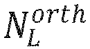


-
Fig. 12 shows an exemplary arrangement of auser communication device 112 according to an embodiment of the present invention. Theuser communication device 112 is arranged to use one or more pilot sequences, generated by thepilot sequence generator 1 for uplink and/or for downlink transmissions. Theuser communication device 112 is an exemplary representative of any of the above mentioned user communication devices 321_1, ..., 321_k, 322_1, ..., 32_z. - According to the present embodiment, the
user communication device 112 comprises atransmitting entity 1122, configured to execute transmission of data and pilot symbols, and areceiving entity 1123, configured to execute reception of data and of pilot symbols. According to an embodiment, the transmittingentity 1122 and the receivingentity 1123 are provided as one entity (e.g., transceiver), as indicated inFig. 12 by the box with dashed lines. Thus, any one of the transmission steps, which is described herein as being executed by auser communication device 112, is particularly executed by the transmittingentity 1122. Any one of the reception steps, which is described herein as being executed by auser communication device 112, is particularly executed by the receivingentity 1123. For example, the receiving entity is configured to receive instructions from thepilot sequence generator 1. - Further, the
user communication device 112 comprises one or moredata storing entities 1124 configured to store data. For example, at least one of the one ormore storing entities 1124 is configured to store aplurality 111 of look-up tables 1111_1, 1111_2, ..., 1111_L. As stated above, in each look-up table 1111_1, 1111_2, ..., 1111_L of theplurality 111 of look-up tables 1111_1, 1111_2, ..., 1111_L a plurality of pilot sequences is stored, wherein the plurality of pilot sequences is generated by thepilot sequence generator 1. In case of presence of more than one look-up table 1111_1, 1111_2, ..., 1111_L in the one ormore storing entities 1124, a first plurality of pilot sequences of a first look-up table 1111_1 is generated by applying a first M value, which is different from a second M value used for generating a second plurality of pilot sequences of a second look-up table 1111_2, ..., 111 1_L of the plurality of look-up tables 111, and/or by applying a firstcomplex matrix 
complex matrix 
plurality 111 of look-up tables 1111_1, 1111_2, ..., 1111_L comprises look-up tables 1111_1, 1111_2, ..., 1111_L that differ from each other with respect to the M value and/or with respect to the complex matrix W non-orth. - The
user communication device 112 comprises also one ormore processing entities 1121 configured to execute different processing steps, except for the transmission and reception of data or pilot symbols, which are executed accordingly by the transmittingentity 1122 and the receivingentity 1123. Thus, any one of the steps, which is executed by theuser communication device 112 and which does not refer to data or pilot transmission, reception or storage, is particularly executed by at least one of the one ormore processing entities 1121. - Particularly, according to an embodiment, the user communication device 112 (particularly, the receiving
entity 1123 of the user communication device 112) is configured to receive, for example, a signaling message comprising one or more instructions from thepilot sequence generator 1 and to pass it to theprocessing entity 1121 which interprets the signaling message to extract the instructions incorporated in it. The instructions and thus the signaling message comprise an index of a look-up table 1111_1, 1111_2, ..., 1111_L, from theplurality 111 of L look-up tables 1111_1, 1111_2, ..., 111 1_L, storing a plurality of pilot sequences, and an index of a pilot sequence of the look-up table 1111_1, 1111_2, ..., 1111_L to be used by theuser communication device 112 for uplink pilot transmission and/or downlink channel estimation. For instance, uplink pilot transmission is executed by the transmittingentity 1122 of theuser communication device 112 which transmits the symbols of the pilot sequence selected by at least one of the one ormore processing entities 1121 based on the signaling message received by the receivingentity 1123. - The invention has been described in conjunction with various embodiments herein. However, other variations to the enclosed embodiments can be understood and effected by those skilled in the art and practicing the claimed invention, from a study of the drawings, the disclosure and the appended claims. In the claims, the word "comprising" does not exclude other elements or steps, and the indefinite article "a" or "an" does not exclude a plurality. The mere fact that certain measures are recited in mutually different dependent claims does not indicate that a combination of these measures cannot be used to advantage.
Claims (13)
- A pilot sequence generator (1) arranged to generate pilot sequences for an uplink and/or for a downlink transmission, wherein the pilot sequence generator is configured to:- generate (21) a pilot sequence set comprising M+1 pilot sequence sub-sets, wherein M is a positive integer that is equal to or greater than one, wherein the pilot sequence generator (1) is configured to generate the pilot sequence set comprising the M+1 pilot sequence sub-sets by executing the following:- dividing (41) an initial pilot sequence set, comprising orthogonal pilot sequences, in a non-processed pilot sequence sub-set and M to-be-processed pilot sequence sub-sets; and- generating (42) M processed non-orthogonal pilot sequence sub-sets, wherein a processing unit (11) is configured, for each to-be-processed pilot sequence sub-set of the M to-be-processed pilot sequence sub-sets, to generate a processed non-orthogonal pilot sequence sub-set by multiplying a to-be-processed pilot sequence sub-set matrix, comprising pilot sequences of the respective to-be-processed pilot sequence sub-set as columns, with a complex matrix, wherein columns of matrix resulting from the multiplication represent the respective processed non-orthogonal pilot sequence sub-set; the M+1 pilot sequence sub-sets comprise the non-processed pilot sequence sub-set and the M processed non-orthogonal pilot sequence sub-sets, wherein the complex matrix is a Nnon-orth × Knon-orth matrix, Nnon-orth < Knon-orth , and columns of the complex matrix are any Knon-orth points on a Nnon-orth -dimensional complex sphere of radius 1 with a minimal pairwise angle that is as large as possible, wherein the pilot sequences of the respective non-orthogonal pilot sequence sub-set are not orthogonal to each other, wherein each non-orthogonal pilot sequence sub-set of the M non-orthogonal pilot sequence sub-sets is orthogonal to each other non-orthogonal pilot sequence sub-set of the M non-orthogonal pilot sequence sub-sets;- assign (22) the M+1 pilot sequence sub-sets to M+1 groups of user communication devices, wherein each pilot sequence sub-set of the M+1 pilot sequence sub-sets is assigned to one group of user communication devices, wherein each group of user communication devices comprises one or more user communication devices, and wherein, by the assignment, the one or more user communication devices of each group of user communication devices of the M+1 groups of user communication devices are configured to use, for the uplink and/or for the downlink transmission, pilot sequences of the pilot sequence sub-set assigned to the respective group of user communication devices.
- The pilot sequence generator according to claim 1, wherein the pilot sequence generator is configured to execute the assignment based on criteria including at least one of the following: user communication device service requirements, user communication device channel conditions, including channel statistics, user communication device position within the cell and/or user communication device distance to a serving base station.
- The pilot sequence generator according to any one of the preceding claims, wherein the assigning (22) comprises, for each pilot sequence sub-set of the M+1 pilot sequence sub-sets, assigning pilot sequences of the pilot sequence sub-set to the one or more user communication devices of the group of user communication devices, which is assigned to the pilot sequence sub-set.
- The pilot sequence generator according to claim 1, wherein the non-processed pilot sequence sub-set comprises at least one pilot sequence, and/or wherein each to-be-processed pilot sequence sub-set of the M to-be-processed pilot sequence sub-sets comprises at least two pilot sequences.
- The pilot sequence generator according to claim 1 or 4, wherein a first to-be-processed pilot sequence sub-set of the M to-be-processed pilot sequence sub-sets has a number of pilot sequences that is different from a number of pilot sequences of a second to-be-processed pilot sequence sub-set of the M to-be-processed pilot sequence sub-sets, and/or wherein a first processed non-orthogonal pilot sequence sub-set of the M processed non-orthogonal pilot sequence sub-sets has a number of pilot sequences that is different from a number of pilot sequences of a second processed non-orthogonal pilot sequence sub-set of the M processed non-orthogonal pilot sequence sub-sets.
- The pilot sequence generator according to any one of claims 1, 4 to 5, wherein, the non-processed pilot sequence sub-set is empty and all the generated pilot sequences are in the M processed non-orthogonal pilot sequence sub-sets.
- The pilot sequence generator according to any one of claims 1, 4 to 6, wherein, the non-processed pilot sequence sub-set comprises at least two pilot sequences, and wherein each one of the pilot sequences of the non-processed pilot sequence sub-set is orthogonal to each further pilot sequence of the non-processed pilot sequence sub-set.
- The pilot sequence generator according to any one of claims 1, 4 to 7, wherein the number of rows of the complex matrix is equal to the number of columns of the to-be-processed pilot sequence sub-set matrix, comprising pilot sequences of the respective to-be-processed pilot sequence sub-set as columns, and wherein a number of columns of the complex matrix is greater than the number of rows of the complex matrix.
- The pilot sequence generator according to any one of claims 1, 4 to 8, wherein the pilot sequence generator is configured to execute said assigning by: assigning pilot sequences of the non-processed pilot sequence sub-set to a first group of user communication devices of the M+1 groups of user communication devices; and by assigning pilot sequences of each processed non-orthogonal pilot sequence sub-set of the M processed non-orthogonal pilot sequence sub-sets to a corresponding further group of user communication devices of the M+1 groups of user communication devices.
- The pilot sequence generator according to any one of claims 1 to 9, wherein the pilot sequence generator is configured to transmit a signaling message to a user communication device of a group of user communication devices of the M+1 groups of user communication devices, wherein the signaling message comprises an index of a look-up table, storing a plurality of pilot sequences, and an index of a pilot sequence of the look-up table to be used by the user communication device.
- A method arranged to generate pilot sequences for an uplink and/or for a downlink transmission wherein the method comprises the following steps of:- generating (21) a pilot sequence set comprising M+1 pilot sequence sub-sets, wherein M is a positive integer that is equal to or greater than one, wherein the generating (21) the pilot sequence set comprising the M+1 pilot sequence sub-sets comprises the following sub-steps:- dividing (41) an initial pilot sequence set, comprising orthogonal pilot sequences, in a non-processed pilot sequence sub-set and M to-be-processed pilot sequence sub-sets; and- generating (42) M processed non-orthogonal pilot sequence sub-sets, wherein a processing unit (11) is configured, for each to-be-processed pilot sequence sub-set of the M to-be-processed pilot sequence sub-sets, to generate a processed non-orthogonal pilot sequence sub-set by multiplying a to-be-processed pilot sequence sub-set matrix, comprising pilot sequences of the respective to-be-processed pilot sequence sub-set as columns, with a complex matrix, wherein columns of matrix resulting from the multiplication represent the respective processed non-orthogonal pilot sequence sub-set; the M+1 pilot sequence sub-sets comprise the non-processed pilot sequence sub-set and the M processed non-orthogonal pilot sequence sub-sets, wherein the complex matrix is a Nnon-orth × Knon-orth matrix, Nnon-orth < Knon-orth , and columns of the complex matrix are any Knon-orth points on a Nnon-orth -dimensional complex sphere of radius 1 with a minimal pairwise angle that is as large as possible, wherein the pilot sequences of the respective non-orthogonal pilot sequence sub-set are not orthogonal to each other, wherein each non-orthogonal pilot sequence sub-set of the M non-orthogonal pilot sequence sub-sets is orthogonal to each other non-orthogonal pilot sequence sub-set of the M non-orthogonal pilot sequence sub-sets;- assigning (22) the M+1 pilot sequence sub-sets to M+1 groups of user communication devices, wherein each pilot sequence sub-set of the M+1 pilot sequence sub-sets is assigned to one group of user communication devices, wherein each group of user communication devices comprises one or more user communication devices, and wherein, by the assignment, the one or more user communication devices of each group of user communication devices of the M+1 groups of user communication devices are configured to use, for the uplink and/or for the downlink transmission, pilot sequences of the pilot sequence sub-set assigned to the respective group of user communication devices.
- A channel estimator (7) arranged to execute a channel estimation with regard to pilot sequences generated by a pilot sequence generator (1) according to any one of claims 1, 4 to 10, wherein the channel estimator is configured to estimate a channel of a user communication device, to which a pilot sequence of a processed non-orthogonal pilot sequence sub-set of the M processed non-orthogonal pilot sequence sub-sets has been assigned, by executing one of the following:- a single user channel estimation method (81) by use of one or more signal samples received in response to a transmission of symbols of the pilot sequence, and by use of a single column of the complex matrix, which has been used for generating the processed non-orthogonal pilot sequence sub-set of the M processed non-orthogonal pilot sequence sub-sets, and by use of the to-be-processed pilot sequence sub-set of the pilot sequences, based on which the processed non-orthogonal pilot sequence sub-set has been generated;- a joint channel estimation method (82) by use of: the one or more signal samples, the complex matrix, and the to-be-processed pilot sequence sub-set.
- A method arranged to execute a channel estimation with regard to pilot sequences generated by a pilot sequence generator (1) according to any one of claims 1, 4 to 10, wherein the method comprises an estimation of a channel of a user communication device, to which a pilot sequence of a processed non-orthogonal pilot sequence sub-set of the M processed non-orthogonal pilot sequence sub-sets has been assigned, said estimation comprising one of the following:- execution of a single user channel estimation method (81) by use of one or more signal samples received in response to a transmission of symbols of the pilot sequence, and by use of a single column of the complex matrix, which has been used for generating the processed non-orthogonal pilot sequence sub-set of the M processed non-orthogonal pilot sequence sub-sets, and by use of the to-be-processed pilot sequence sub-set of the pilot sequences, based on which the processed non-orthogonal pilot sequence sub-set has been generated;- execution of a joint channel estimation method (82) by use of: the one or more signal samples, the complex matrix, and the to-be-processed pilot sequence sub-set.
Applications Claiming Priority (1)
| Application Number | Priority Date | Filing Date | Title |
|---|---|---|---|
| PCT/EP2016/079751 WO2018103815A1 (en) | 2016-12-05 | 2016-12-05 | Pilot sequence generator and corresponding method and channel estimator and corresponding method |
Publications (2)
| Publication Number | Publication Date |
|---|---|
| EP3529960A1 EP3529960A1 (en) | 2019-08-28 |
| EP3529960B1 true EP3529960B1 (en) | 2023-02-22 |
Family
ID=57482439
Family Applications (1)
| Application Number | Title | Priority Date | Filing Date |
|---|---|---|---|
| EP16805842.8A Active EP3529960B1 (en) | 2016-12-05 | 2016-12-05 | Pilot sequence generator and corresponding method and channel estimator and corresponding method |
Country Status (3)
| Country | Link |
|---|---|
| EP (1) | EP3529960B1 (en) |
| CN (1) | CN110050451B (en) |
| WO (1) | WO2018103815A1 (en) |
Families Citing this family (2)
| Publication number | Priority date | Publication date | Assignee | Title |
|---|---|---|---|---|
| CN113938864B (en) * | 2020-06-29 | 2025-12-12 | 华为技术有限公司 | A sequence generation method and related equipment |
| CN112564874B (en) * | 2020-11-04 | 2022-09-13 | 展讯通信(上海)有限公司 | Pilot frequency sequence generation method and device |
Family Cites Families (6)
| Publication number | Priority date | Publication date | Assignee | Title |
|---|---|---|---|---|
| CN101056152B (en) * | 2006-04-30 | 2010-08-04 | 华为技术有限公司 | Transmission method and system in universal mobile communication system |
| US8705642B2 (en) * | 2009-10-20 | 2014-04-22 | King Fahd University Of Petroleum And Minerals | Method for mitigating interference in OFDM communications systems |
| WO2015020290A1 (en) * | 2013-08-09 | 2015-02-12 | Lg Electronics Inc. | Antenna combining for massive mimo scheme |
| EP3419201A1 (en) * | 2014-06-24 | 2018-12-26 | Huawei Technologies Co., Ltd. | Method and apparatus for multiple access in a wireless communication system |
| US9774613B2 (en) * | 2014-12-15 | 2017-09-26 | Sophos Limited | Server drift monitoring |
| CN111432486B (en) * | 2015-05-08 | 2023-11-21 | 华为技术有限公司 | Device and method for controlling resource allocation in wireless communication network |
-
2016
- 2016-12-05 EP EP16805842.8A patent/EP3529960B1/en active Active
- 2016-12-05 WO PCT/EP2016/079751 patent/WO2018103815A1/en not_active Ceased
- 2016-12-05 CN CN201680091422.1A patent/CN110050451B/en active Active
Also Published As
| Publication number | Publication date |
|---|---|
| CN110050451A (en) | 2019-07-23 |
| EP3529960A1 (en) | 2019-08-28 |
| CN110050451B (en) | 2020-12-15 |
| WO2018103815A1 (en) | 2018-06-14 |
Similar Documents
| Publication | Publication Date | Title |
|---|---|---|
| JP5663163B2 (en) | Method, terminal and uplink system for determining uplink demodulated pilot sequence | |
| CN102804630B (en) | Method and apparatus for transmitting reference signals in uplink multiple-input multiple-output (MIMO) transmission | |
| US9425936B2 (en) | Method and apparatus for generating a reference signal sequence in a wireless communication system | |
| US9584275B2 (en) | Method and apparatus for generating an uplink reference signal sequence in a wireless communication system | |
| CN102362443B (en) | Method and device for transmitting a reference signal in a multi-antenna system | |
| CN102437986B (en) | Reference signal mapping method and device | |
| CN101877689B (en) | Data transmitting method and device thereof as well as data receiving method and device thereof | |
| US20140369311A1 (en) | Method, Terminal And Base Station For Multi-User Interference Suppression | |
| JP2012524453A (en) | Method and apparatus for transmitting a reference signal | |
| EP3780527B1 (en) | Method and apparatus for estimating channel in wireless communication system | |
| CN102100045B (en) | Data transmission processing method and device, data reception processing method and device | |
| WO2019030894A1 (en) | Transmission device | |
| JP2021106394A (en) | Transmission device, receiving device, base station, terminal, and transmission method | |
| CN111556570B (en) | Apparatus, method and computer program for wireless communication using multiple access | |
| EP2352246B1 (en) | Multi-user mimo system, receiver apparatus and transmitter apparatus | |
| US20130343320A1 (en) | Terminal device, base station device, and wireless communication system | |
| Mukherjee et al. | Timing advance estimation and beamforming of random access response in crowded TDD massive MIMO systems | |
| US10917221B2 (en) | Base station apparatus, terminal apparatus, and communication method | |
| CN110050451B (en) | Pilot sequence generator and corresponding method and channel estimator and corresponding method | |
| CN114172778A (en) | Parameter configuration, parameter receiving method and device, and storage medium | |
| WO2012140847A1 (en) | Transmitter apparatus, receiver apparatus, signal generating method and quality estimating method | |
| Moyella et al. | Downlink Beamforming in 5G Massive MU-MIMO Systems Using SRS-Based Channel Estimation |
Legal Events
| Date | Code | Title | Description |
|---|---|---|---|
| STAA | Information on the status of an ep patent application or granted ep patent |
Free format text: STATUS: UNKNOWN |
|
| STAA | Information on the status of an ep patent application or granted ep patent |
Free format text: STATUS: THE INTERNATIONAL PUBLICATION HAS BEEN MADE |
|
| PUAI | Public reference made under article 153(3) epc to a published international application that has entered the european phase |
Free format text: ORIGINAL CODE: 0009012 |
|
| STAA | Information on the status of an ep patent application or granted ep patent |
Free format text: STATUS: REQUEST FOR EXAMINATION WAS MADE |
|
| 17P | Request for examination filed |
Effective date: 20190521 |
|
| AK | Designated contracting states |
Kind code of ref document: A1 Designated state(s): AL AT BE BG CH CY CZ DE DK EE ES FI FR GB GR HR HU IE IS IT LI LT LU LV MC MK MT NL NO PL PT RO RS SE SI SK SM TR |
|
| AX | Request for extension of the european patent |
Extension state: BA ME |
|
| DAV | Request for validation of the european patent (deleted) | ||
| DAX | Request for extension of the european patent (deleted) | ||
| STAA | Information on the status of an ep patent application or granted ep patent |
Free format text: STATUS: EXAMINATION IS IN PROGRESS |
|
| 17Q | First examination report despatched |
Effective date: 20210416 |
|
| GRAP | Despatch of communication of intention to grant a patent |
Free format text: ORIGINAL CODE: EPIDOSNIGR1 |
|
| STAA | Information on the status of an ep patent application or granted ep patent |
Free format text: STATUS: GRANT OF PATENT IS INTENDED |
|
| INTG | Intention to grant announced |
Effective date: 20221031 |
|
| GRAS | Grant fee paid |
Free format text: ORIGINAL CODE: EPIDOSNIGR3 |
|
| GRAA | (expected) grant |
Free format text: ORIGINAL CODE: 0009210 |
|
| STAA | Information on the status of an ep patent application or granted ep patent |
Free format text: STATUS: THE PATENT HAS BEEN GRANTED |
|
| AK | Designated contracting states |
Kind code of ref document: B1 Designated state(s): AL AT BE BG CH CY CZ DE DK EE ES FI FR GB GR HR HU IE IS IT LI LT LU LV MC MK MT NL NO PL PT RO RS SE SI SK SM TR |
|
| REG | Reference to a national code |
Ref country code: GB Ref legal event code: FG4D |
|
| REG | Reference to a national code |
Ref country code: CH Ref legal event code: EP |
|
| REG | Reference to a national code |
Ref country code: AT Ref legal event code: REF Ref document number: 1550218 Country of ref document: AT Kind code of ref document: T Effective date: 20230315 Ref country code: IE Ref legal event code: FG4D |
|
| REG | Reference to a national code |
Ref country code: DE Ref legal event code: R096 Ref document number: 602016077967 Country of ref document: DE |
|
| REG | Reference to a national code |
Ref country code: SE Ref legal event code: TRGR |
|
| REG | Reference to a national code |
Ref country code: LT Ref legal event code: MG9D |
|
| P01 | Opt-out of the competence of the unified patent court (upc) registered |
Effective date: 20230524 |
|
| REG | Reference to a national code |
Ref country code: NL Ref legal event code: MP Effective date: 20230222 |
|
| REG | Reference to a national code |
Ref country code: AT Ref legal event code: MK05 Ref document number: 1550218 Country of ref document: AT Kind code of ref document: T Effective date: 20230222 |
|
| PG25 | Lapsed in a contracting state [announced via postgrant information from national office to epo] |
Ref country code: RS Free format text: LAPSE BECAUSE OF FAILURE TO SUBMIT A TRANSLATION OF THE DESCRIPTION OR TO PAY THE FEE WITHIN THE PRESCRIBED TIME-LIMIT Effective date: 20230222 Ref country code: PT Free format text: LAPSE BECAUSE OF FAILURE TO SUBMIT A TRANSLATION OF THE DESCRIPTION OR TO PAY THE FEE WITHIN THE PRESCRIBED TIME-LIMIT Effective date: 20230622 Ref country code: NO Free format text: LAPSE BECAUSE OF FAILURE TO SUBMIT A TRANSLATION OF THE DESCRIPTION OR TO PAY THE FEE WITHIN THE PRESCRIBED TIME-LIMIT Effective date: 20230522 Ref country code: NL Free format text: LAPSE BECAUSE OF FAILURE TO SUBMIT A TRANSLATION OF THE DESCRIPTION OR TO PAY THE FEE WITHIN THE PRESCRIBED TIME-LIMIT Effective date: 20230222 Ref country code: LV Free format text: LAPSE BECAUSE OF FAILURE TO SUBMIT A TRANSLATION OF THE DESCRIPTION OR TO PAY THE FEE WITHIN THE PRESCRIBED TIME-LIMIT Effective date: 20230222 Ref country code: LT Free format text: LAPSE BECAUSE OF FAILURE TO SUBMIT A TRANSLATION OF THE DESCRIPTION OR TO PAY THE FEE WITHIN THE PRESCRIBED TIME-LIMIT Effective date: 20230222 Ref country code: HR Free format text: LAPSE BECAUSE OF FAILURE TO SUBMIT A TRANSLATION OF THE DESCRIPTION OR TO PAY THE FEE WITHIN THE PRESCRIBED TIME-LIMIT Effective date: 20230222 Ref country code: ES Free format text: LAPSE BECAUSE OF FAILURE TO SUBMIT A TRANSLATION OF THE DESCRIPTION OR TO PAY THE FEE WITHIN THE PRESCRIBED TIME-LIMIT Effective date: 20230222 Ref country code: AT Free format text: LAPSE BECAUSE OF FAILURE TO SUBMIT A TRANSLATION OF THE DESCRIPTION OR TO PAY THE FEE WITHIN THE PRESCRIBED TIME-LIMIT Effective date: 20230222 |
|
| PG25 | Lapsed in a contracting state [announced via postgrant information from national office to epo] |
Ref country code: PL Free format text: LAPSE BECAUSE OF FAILURE TO SUBMIT A TRANSLATION OF THE DESCRIPTION OR TO PAY THE FEE WITHIN THE PRESCRIBED TIME-LIMIT Effective date: 20230222 Ref country code: IS Free format text: LAPSE BECAUSE OF FAILURE TO SUBMIT A TRANSLATION OF THE DESCRIPTION OR TO PAY THE FEE WITHIN THE PRESCRIBED TIME-LIMIT Effective date: 20230622 Ref country code: GR Free format text: LAPSE BECAUSE OF FAILURE TO SUBMIT A TRANSLATION OF THE DESCRIPTION OR TO PAY THE FEE WITHIN THE PRESCRIBED TIME-LIMIT Effective date: 20230523 Ref country code: FI Free format text: LAPSE BECAUSE OF FAILURE TO SUBMIT A TRANSLATION OF THE DESCRIPTION OR TO PAY THE FEE WITHIN THE PRESCRIBED TIME-LIMIT Effective date: 20230222 |
|
| PG25 | Lapsed in a contracting state [announced via postgrant information from national office to epo] |
Ref country code: SM Free format text: LAPSE BECAUSE OF FAILURE TO SUBMIT A TRANSLATION OF THE DESCRIPTION OR TO PAY THE FEE WITHIN THE PRESCRIBED TIME-LIMIT Effective date: 20230222 Ref country code: RO Free format text: LAPSE BECAUSE OF FAILURE TO SUBMIT A TRANSLATION OF THE DESCRIPTION OR TO PAY THE FEE WITHIN THE PRESCRIBED TIME-LIMIT Effective date: 20230222 Ref country code: EE Free format text: LAPSE BECAUSE OF FAILURE TO SUBMIT A TRANSLATION OF THE DESCRIPTION OR TO PAY THE FEE WITHIN THE PRESCRIBED TIME-LIMIT Effective date: 20230222 Ref country code: DK Free format text: LAPSE BECAUSE OF FAILURE TO SUBMIT A TRANSLATION OF THE DESCRIPTION OR TO PAY THE FEE WITHIN THE PRESCRIBED TIME-LIMIT Effective date: 20230222 Ref country code: CZ Free format text: LAPSE BECAUSE OF FAILURE TO SUBMIT A TRANSLATION OF THE DESCRIPTION OR TO PAY THE FEE WITHIN THE PRESCRIBED TIME-LIMIT Effective date: 20230222 |
|
| REG | Reference to a national code |
Ref country code: DE Ref legal event code: R097 Ref document number: 602016077967 Country of ref document: DE |
|
| PG25 | Lapsed in a contracting state [announced via postgrant information from national office to epo] |
Ref country code: SK Free format text: LAPSE BECAUSE OF FAILURE TO SUBMIT A TRANSLATION OF THE DESCRIPTION OR TO PAY THE FEE WITHIN THE PRESCRIBED TIME-LIMIT Effective date: 20230222 |
|
| PLBE | No opposition filed within time limit |
Free format text: ORIGINAL CODE: 0009261 |
|
| STAA | Information on the status of an ep patent application or granted ep patent |
Free format text: STATUS: NO OPPOSITION FILED WITHIN TIME LIMIT |
|
| 26N | No opposition filed |
Effective date: 20231123 |
|
| PG25 | Lapsed in a contracting state [announced via postgrant information from national office to epo] |
Ref country code: SI Free format text: LAPSE BECAUSE OF FAILURE TO SUBMIT A TRANSLATION OF THE DESCRIPTION OR TO PAY THE FEE WITHIN THE PRESCRIBED TIME-LIMIT Effective date: 20230222 |
|
| PG25 | Lapsed in a contracting state [announced via postgrant information from national office to epo] |
Ref country code: IT Free format text: LAPSE BECAUSE OF FAILURE TO SUBMIT A TRANSLATION OF THE DESCRIPTION OR TO PAY THE FEE WITHIN THE PRESCRIBED TIME-LIMIT Effective date: 20230222 |
|
| REG | Reference to a national code |
Ref country code: DE Ref legal event code: R119 Ref document number: 602016077967 Country of ref document: DE |
|
| REG | Reference to a national code |
Ref country code: CH Ref legal event code: PL |
|
| PG25 | Lapsed in a contracting state [announced via postgrant information from national office to epo] |
Ref country code: LU Free format text: LAPSE BECAUSE OF NON-PAYMENT OF DUE FEES Effective date: 20231205 |
|
| PG25 | Lapsed in a contracting state [announced via postgrant information from national office to epo] |
Ref country code: MC Free format text: LAPSE BECAUSE OF FAILURE TO SUBMIT A TRANSLATION OF THE DESCRIPTION OR TO PAY THE FEE WITHIN THE PRESCRIBED TIME-LIMIT Effective date: 20230222 |
|
| PG25 | Lapsed in a contracting state [announced via postgrant information from national office to epo] |
Ref country code: MC Free format text: LAPSE BECAUSE OF FAILURE TO SUBMIT A TRANSLATION OF THE DESCRIPTION OR TO PAY THE FEE WITHIN THE PRESCRIBED TIME-LIMIT Effective date: 20230222 Ref country code: LU Free format text: LAPSE BECAUSE OF NON-PAYMENT OF DUE FEES Effective date: 20231205 |
|
| REG | Reference to a national code |
Ref country code: IE Ref legal event code: MM4A |
|
| PG25 | Lapsed in a contracting state [announced via postgrant information from national office to epo] |
Ref country code: DE Free format text: LAPSE BECAUSE OF NON-PAYMENT OF DUE FEES Effective date: 20240702 Ref country code: IE Free format text: LAPSE BECAUSE OF NON-PAYMENT OF DUE FEES Effective date: 20231205 |
|
| PG25 | Lapsed in a contracting state [announced via postgrant information from national office to epo] |
Ref country code: FR Free format text: LAPSE BECAUSE OF NON-PAYMENT OF DUE FEES Effective date: 20231231 |
|
| PG25 | Lapsed in a contracting state [announced via postgrant information from national office to epo] |
Ref country code: CH Free format text: LAPSE BECAUSE OF NON-PAYMENT OF DUE FEES Effective date: 20231231 |
|
| PG25 | Lapsed in a contracting state [announced via postgrant information from national office to epo] |
Ref country code: IE Free format text: LAPSE BECAUSE OF NON-PAYMENT OF DUE FEES Effective date: 20231205 Ref country code: FR Free format text: LAPSE BECAUSE OF NON-PAYMENT OF DUE FEES Effective date: 20231231 Ref country code: DE Free format text: LAPSE BECAUSE OF NON-PAYMENT OF DUE FEES Effective date: 20240702 Ref country code: CH Free format text: LAPSE BECAUSE OF NON-PAYMENT OF DUE FEES Effective date: 20231231 |
|
| PG25 | Lapsed in a contracting state [announced via postgrant information from national office to epo] |
Ref country code: BG Free format text: LAPSE BECAUSE OF FAILURE TO SUBMIT A TRANSLATION OF THE DESCRIPTION OR TO PAY THE FEE WITHIN THE PRESCRIBED TIME-LIMIT Effective date: 20230222 |
|
| PG25 | Lapsed in a contracting state [announced via postgrant information from national office to epo] |
Ref country code: BG Free format text: LAPSE BECAUSE OF FAILURE TO SUBMIT A TRANSLATION OF THE DESCRIPTION OR TO PAY THE FEE WITHIN THE PRESCRIBED TIME-LIMIT Effective date: 20230222 |
|
| PG25 | Lapsed in a contracting state [announced via postgrant information from national office to epo] |
Ref country code: CY Free format text: LAPSE BECAUSE OF FAILURE TO SUBMIT A TRANSLATION OF THE DESCRIPTION OR TO PAY THE FEE WITHIN THE PRESCRIBED TIME-LIMIT; INVALID AB INITIO Effective date: 20161205 |
|
| PG25 | Lapsed in a contracting state [announced via postgrant information from national office to epo] |
Ref country code: HU Free format text: LAPSE BECAUSE OF FAILURE TO SUBMIT A TRANSLATION OF THE DESCRIPTION OR TO PAY THE FEE WITHIN THE PRESCRIBED TIME-LIMIT; INVALID AB INITIO Effective date: 20161205 |
|
| PG25 | Lapsed in a contracting state [announced via postgrant information from national office to epo] |
Ref country code: TR Free format text: LAPSE BECAUSE OF FAILURE TO SUBMIT A TRANSLATION OF THE DESCRIPTION OR TO PAY THE FEE WITHIN THE PRESCRIBED TIME-LIMIT Effective date: 20230222 |
|
| PGFP | Annual fee paid to national office [announced via postgrant information from national office to epo] |
Ref country code: GB Payment date: 20251030 Year of fee payment: 10 |
|
| PGFP | Annual fee paid to national office [announced via postgrant information from national office to epo] |
Ref country code: BE Payment date: 20251117 Year of fee payment: 10 |
|
| PGFP | Annual fee paid to national office [announced via postgrant information from national office to epo] |
Ref country code: SE Payment date: 20251112 Year of fee payment: 10 |