EP3529957B1 - Synthesis of near-constant modulus waveform for high frequency transmission - Google Patents
Synthesis of near-constant modulus waveform for high frequency transmission Download PDFInfo
- Publication number
- EP3529957B1 EP3529957B1 EP16791638.6A EP16791638A EP3529957B1 EP 3529957 B1 EP3529957 B1 EP 3529957B1 EP 16791638 A EP16791638 A EP 16791638A EP 3529957 B1 EP3529957 B1 EP 3529957B1
- Authority
- EP
- European Patent Office
- Prior art keywords
- signal
- auxiliary
- primary
- sequence
- processor
- Prior art date
- Legal status (The legal status is an assumption and is not a legal conclusion. Google has not performed a legal analysis and makes no representation as to the accuracy of the status listed.)
- Active
Links
Images






Classifications
-
- H—ELECTRICITY
- H04—ELECTRIC COMMUNICATION TECHNIQUE
- H04L—TRANSMISSION OF DIGITAL INFORMATION, e.g. TELEGRAPHIC COMMUNICATION
- H04L27/00—Modulated-carrier systems
- H04L27/26—Systems using multi-frequency codes
- H04L27/2601—Multicarrier modulation systems
- H04L27/2614—Peak power aspects
-
- G—PHYSICS
- G06—COMPUTING OR CALCULATING; COUNTING
- G06F—ELECTRIC DIGITAL DATA PROCESSING
- G06F17/00—Digital computing or data processing equipment or methods, specially adapted for specific functions
- G06F17/10—Complex mathematical operations
- G06F17/14—Fourier, Walsh or analogous domain transformations, e.g. Laplace, Hilbert, Karhunen-Loeve, transforms
- G06F17/141—Discrete Fourier transforms
-
- H—ELECTRICITY
- H04—ELECTRIC COMMUNICATION TECHNIQUE
- H04B—TRANSMISSION
- H04B7/00—Radio transmission systems, i.e. using radiation field
- H04B7/02—Diversity systems; Multi-antenna system, i.e. transmission or reception using multiple antennas
- H04B7/04—Diversity systems; Multi-antenna system, i.e. transmission or reception using multiple antennas using two or more spaced independent antennas
- H04B7/0413—MIMO systems
-
- H—ELECTRICITY
- H04—ELECTRIC COMMUNICATION TECHNIQUE
- H04L—TRANSMISSION OF DIGITAL INFORMATION, e.g. TELEGRAPHIC COMMUNICATION
- H04L25/00—Baseband systems
- H04L25/02—Details ; arrangements for supplying electrical power along data transmission lines
- H04L25/03—Shaping networks in transmitter or receiver, e.g. adaptive shaping networks
- H04L25/03828—Arrangements for spectral shaping; Arrangements for providing signals with specified spectral properties
- H04L25/03834—Arrangements for spectral shaping; Arrangements for providing signals with specified spectral properties using pulse shaping
-
- H—ELECTRICITY
- H04—ELECTRIC COMMUNICATION TECHNIQUE
- H04L—TRANSMISSION OF DIGITAL INFORMATION, e.g. TELEGRAPHIC COMMUNICATION
- H04L27/00—Modulated-carrier systems
- H04L27/18—Phase-modulated carrier systems, i.e. using phase-shift keying
- H04L27/20—Modulator circuits; Transmitter circuits
- H04L27/2032—Modulator circuits; Transmitter circuits for discrete phase modulation, e.g. in which the phase of the carrier is modulated in a nominally instantaneous manner
- H04L27/2053—Modulator circuits; Transmitter circuits for discrete phase modulation, e.g. in which the phase of the carrier is modulated in a nominally instantaneous manner using more than one carrier, e.g. carriers with different phases
- H04L27/206—Modulator circuits; Transmitter circuits for discrete phase modulation, e.g. in which the phase of the carrier is modulated in a nominally instantaneous manner using more than one carrier, e.g. carriers with different phases using a pair of orthogonal carriers, e.g. quadrature carriers
- H04L27/2067—Modulator circuits; Transmitter circuits for discrete phase modulation, e.g. in which the phase of the carrier is modulated in a nominally instantaneous manner using more than one carrier, e.g. carriers with different phases using a pair of orthogonal carriers, e.g. quadrature carriers with more than two phase states
- H04L27/2078—Modulator circuits; Transmitter circuits for discrete phase modulation, e.g. in which the phase of the carrier is modulated in a nominally instantaneous manner using more than one carrier, e.g. carriers with different phases using a pair of orthogonal carriers, e.g. quadrature carriers with more than two phase states in which the phase change per symbol period is constrained
-
- H—ELECTRICITY
- H04—ELECTRIC COMMUNICATION TECHNIQUE
- H04L—TRANSMISSION OF DIGITAL INFORMATION, e.g. TELEGRAPHIC COMMUNICATION
- H04L27/00—Modulated-carrier systems
- H04L27/26—Systems using multi-frequency codes
- H04L27/2601—Multicarrier modulation systems
- H04L27/2602—Signal structure
-
- H—ELECTRICITY
- H04—ELECTRIC COMMUNICATION TECHNIQUE
- H04L—TRANSMISSION OF DIGITAL INFORMATION, e.g. TELEGRAPHIC COMMUNICATION
- H04L27/00—Modulated-carrier systems
- H04L27/26—Systems using multi-frequency codes
- H04L27/2601—Multicarrier modulation systems
- H04L27/2626—Arrangements specific to the transmitter only
- H04L27/2627—Modulators
- H04L27/2634—Inverse fast Fourier transform [IFFT] or inverse discrete Fourier transform [IDFT] modulators in combination with other circuits for modulation
- H04L27/2636—Inverse fast Fourier transform [IFFT] or inverse discrete Fourier transform [IDFT] modulators in combination with other circuits for modulation with FFT or DFT modulators, e.g. standard single-carrier frequency-division multiple access [SC-FDMA] transmitter or DFT spread orthogonal frequency division multiplexing [DFT-SOFDM]
-
- H—ELECTRICITY
- H04—ELECTRIC COMMUNICATION TECHNIQUE
- H04L—TRANSMISSION OF DIGITAL INFORMATION, e.g. TELEGRAPHIC COMMUNICATION
- H04L27/00—Modulated-carrier systems
- H04L27/26—Systems using multi-frequency codes
- H04L27/2601—Multicarrier modulation systems
- H04L27/2626—Arrangements specific to the transmitter only
- H04L27/2646—Arrangements specific to the transmitter only using feedback from receiver for adjusting OFDM transmission parameters, e.g. transmission timing or guard interval length
-
- H—ELECTRICITY
- H04—ELECTRIC COMMUNICATION TECHNIQUE
- H04L—TRANSMISSION OF DIGITAL INFORMATION, e.g. TELEGRAPHIC COMMUNICATION
- H04L5/00—Arrangements affording multiple use of the transmission path
- H04L5/0001—Arrangements for dividing the transmission path
- H04L5/0003—Two-dimensional division
- H04L5/0005—Time-frequency
- H04L5/0007—Time-frequency the frequencies being orthogonal, e.g. OFDM(A) or DMT
- H04L5/001—Time-frequency the frequencies being orthogonal, e.g. OFDM(A) or DMT the frequencies being arranged in component carriers
-
- H—ELECTRICITY
- H04—ELECTRIC COMMUNICATION TECHNIQUE
- H04L—TRANSMISSION OF DIGITAL INFORMATION, e.g. TELEGRAPHIC COMMUNICATION
- H04L27/00—Modulated-carrier systems
- H04L27/26—Systems using multi-frequency codes
- H04L27/2601—Multicarrier modulation systems
- H04L27/2626—Arrangements specific to the transmitter only
- H04L27/2627—Modulators
Definitions
- the present invention in some embodiments thereof, relates to generating a high frequency (HF) signal having a low Peak to Average Power Ratio (PAPR) and, more specifically, but not exclusively, to generating a low-PAPR HF signal by complementing the signal with one or more auxiliary signals to increase constancy of the signal's amplitude.
- HF high frequency
- PAPR Peak to Average Power Ratio
- Wireless communication in particular cellular communication, is rapidly evolving to provide higher performance, for example, increased throughput, improved Band-Width (BW) utilization, enhanced coverage, reduced cost equipment and/or the like.
- BW Band-Width
- SC-FDM Single-Carrier Frequency Division Multiplexing
- DFT-s-OFDM Discrete Fourier Transform spread Orthogonal Frequency Division Multiplexing
- EP 1841158 A1 discloses a transmitter for a communication system having high peak-to-average power ratios, including a transmitter for reducing this high ratio by way of a modulation process.
- US 2005/153675 A1 discloses a power amplification device for improving the efficiency in which an amplifier operates with a signal having a peak-to-average power ratio that is high.
- a transmitter comprising a processor adapted to convert a primary sequence of modulation symbols into a primary signal, using a primary pulse shape, convert an auxiliary sequence of modulation symbols, created from the primary sequence, to an auxiliary signal using an auxiliary pulse shape and create a joint output signal based on the primary signal and on the auxiliary signal, wherein the processor is configured to create the auxiliary sequence from the primary sequence by generating each modulation symbol of the auxiliary sequence from a corresponding modulation symbol of the primary sequence and at least two preceding modulation symbols of the primary sequence.
- the processor is configured to perform at one or more of the following operations to the primary sequence, or to the auxiliary sequence, or to a compounded sequence thereof:
- a plurality of finite sub-sequences of consecutive symbols of the primary sequence are cyclically extended to create a plurality of respective finite sub-sequences of consecutive symbols of the auxiliary sequence.
- the processor is adapted for transmission of the output signal using any one of a group:
- the processor is adapted to periodically insert one or more fixed finite sequence of symbols, including a unique word, UW, into the primary sequence.
- the processor is adapted to convert the primary sequence and the auxiliary sequence to frequency domain signals to create the output signal, wherein the resulting frequency domain output signal is converted back to time domain prior to transmission.
- the processor is adapted to periodically insert guard intervals, GIs, into the time domain output signal.
- the guard intervals include one or more member of: a cyclic prefix (CP), a cyclic postfix, a zero prefix (ZP) and a zero tail (ZT).
- the primary sequence modulation symbols map the data stream according to a Binary-Phase Shift Keying (BPSK) modulation scheme.
- BPSK Binary-Phase Shift Keying
- a Peak to Average Power Ratio (PAPR) of the output signal is lower than the PAPR of the primary signal.
- a power of the auxiliary pulse shape used for converting the auxiliary signal is smaller than the power of the primary pulse shape used for converting the primary signal by at least 10dB such that the power of the auxiliary signal is negligible with respect to the power of the primary signal.
- the primary pulse shape and auxiliary pulse shape comply with one or more of a plurality of pulse duration constraints.
- the processor is adapted to create the output signal to comply with at least one of a plurality of signal spectral constraints.
- the primary pulse shape and the auxiliary pulse shape are constructed using an ancestor function.
- the auxiliary pulse shape is based on the primary pulse shape.
- the processor is adapted to perform the superposition in the frequency domain after separately converting the primary sequence and the auxiliary sequence into the frequency and the processor is adapted to join the primary signal and the auxiliary signal through a first partial join in the time domain of the respective primary and auxiliary sequences and a second partial join in the frequency domain.
- the output signal is transmitted simultaneously as a plurality of partial output signals through a plurality of power amplifiers to support a multi input multi output, MIMO, transmission.
- the output signal is transmitted simultaneously as a plurality of partial output signals through a plurality of power amplifiers divided to a plurality of subsets.
- the processor is adapted to create one or more demodulation reference signal similarly to the output signal.
- Another embodiment of the invention relates to a computer program claimed in claim 19.
- the present invention in some embodiments thereof, relates to generating a low-PAPR HF signal and, more specifically, but not exclusively, to generating a low-PAPR HF signal by complementing the signal with one or more auxiliary signals to increase constancy of the signal's amplitude.
- the present invention presents devices, systems and methods for generating SynThesis Of a neaR-constant Modulus (STORM) signals exhibiting high amplitude constancy and hence reduced PAPR.
- the STORM technique may be applied for generating wireless transmission signals compliant with one or more of a plurality of modulation, multiplexing and multiple access (MA) schemes, for example, a Frequency Division Multiplexing (FDM), a Discrete Fourier Transform spread Orthogonal FDM (DFT-s-OFDM), a Single Carrier FDM (SC-FDM), a transmission based on Frequency Division Multiple Access (FDMA) and/or the like utilizing a High Frequency (HF) band, for example, above 6 GHz.
- FDM Frequency Division Multiplexing
- DFT-s-OFDM Discrete Fourier Transform spread Orthogonal FDM
- SC-FDM Single Carrier FDM
- FDMA Frequency Division Multiple Access
- HF High Frequency
- the STORM technique may be further applied for generating Single Carrier (SC) signals.
- the STORM technique is based on generating one or more auxiliary signals that are created from a primary signal carrying a (to be) transmitted data stream.
- the primary signal is combined with the auxiliary signal(s) that complement the primary signal, where the auxiliary signal(s) rectifies the nonzero PAPR of the primary signal to form the STORM signal having increased amplitude constancy and thus reduced PAPR.
- the primary and auxiliary signals are generated using carefully selected and/or constructed primary and auxiliary pulse shapes, respectively. Power of the auxiliary pulse shape(s) is significantly smaller than the power of the primary pulse shape, implying that the power of the auxiliary signal is significantly lower than the power of the primary signal.
- auxiliary sequences of modulation symbols from which the auxiliary signal(s) are generated comprise modulation symbols which depend on a plurality of respective modulation symbols of a primary sequence from which the primary signal is generated.
- the primary sequence modulation symbols maps a (to be) transmitted data bit stream in one or more of a plurality of modulation schemes, for example, Binary Phase-shift Keying (BPSK), Quadrature Phase-shift Keying (QPSK), 8 Phase-shift Keying (8PSK) and/or the like.
- BPSK Binary Phase-shift Keying
- QPSK Quadrature Phase-shift Keying
- 8PSK 8 Phase-shift Keying
- the STORM technique may present multiple advantages compared to currently existing systems and/or methods used for reducing the PAPR of wireless transmission signals.
- the high PAPR implies that the maximum (peak) amplitude may be significantly higher than the mean amplitude of the transmitted signal.
- the high PAPR forces the transmitted signals to be significantly attenuated before being fed into a non-linear Power Amplifier (PA) of a wireless transmitter.
- PA Power Amplifier
- the attenuation is required in order to ensure that the (non-linear) PA is operating in its (near-optimal) operational region and to prevent the PA from entering its saturation region when the amplitude of the (to be) transmitted signal at the PA input is relatively high, thus limiting an undesirable distortion of the transmitted signal.
- some of the currently existing methods may apply one or more add-ons to the transmitter (at different digital-baseband processing stages), for example, clipping or companding and filtering (CAF), Tone Reservation (TR), Tone Insertion/Injection (TI), Peak Cancellation, Selective Mapping (SLM), Partial Transmit Sequences (PTS) and Active Constellation Extension (ACE).
- CAF clipping or companding and filtering
- TR Tone Reservation
- TI Tone Insertion/Injection
- SLM Peak Cancellation
- SLM Selective Mapping
- PTS Partial Transmit Sequences
- ACE Active Constellation Extension
- Some of the currently existing methods may further employ Weighted OverLap & Add (WOLA) and/or filtering (i.e. filtered-OFDM) on the concatenated sequence of OFDM symbols to improve the spectral properties of the overall signal.
- WOLA Weighted OverLap & Add
- filtered-OFDM filtering
- the existing PAPR reduction techniques present some disadvantages due to tradeoffs between one or more characteristics of the transmitted signal, for example:
- Another approach used by the existing techniques of PAPR reduction of OFDM-based waveforms is to perform a DFT precoding (or spreading) of the modulated Quadrature Amplitude Modulation symbols (QAMs) to process their sequence in the frequency domain before mapping it onto the Inverse Fast Fourier Transform (IFFT) input of the OFDM modulator.
- This may allow taking advantage of the Frequency Domain Equalization (FDE) of the OFDM signal at the receiver while reducing the PAPR of the signal to be transmitted.
- the filters used in the frequency domain processing at the transmitter may be typically constrained to satisfy the Nyquist criterion in order to avoid introduction of Inter-Symbol Interference (ISI) between the QAMs within each OFDM symbol.
- ISI Inter-Symbol Interference
- the STORM technique may significantly reduce the PAPR of the transmitted signal, thus reducing the OBO of the PA. Consequently, the STORM technique presents a plurality of additional advantages, for example:
- the present invention may be a system, a method, and/or a computer program product.
- the computer program product may include a computer readable storage medium (or media) having computer readable program instructions thereon for causing a processor to carry out aspects of the present invention.
- the computer readable storage medium can be a tangible device that can retain and store instructions for use by an instruction execution device.
- the computer readable storage medium may be, for example, but is not limited to, an electronic storage device, a magnetic storage device, an optical storage device, an electromagnetic storage device, a semiconductor storage device, or any suitable combination of the foregoing.
- Computer readable program instructions described herein can be downloaded to respective computing/processing devices from a computer readable storage medium or to an external computer or external storage device via a network, for example, the Internet, a local area network, a wide area network and/or a wireless network.
- a network for example, the Internet, a local area network, a wide area network and/or a wireless network.
- the computer readable program instructions may execute entirely on the user's computer, partly on the user's computer such as the user equipment (UE), as a stand-alone software package, partly on the user's computer and partly on a remote computer such as the network apparatus or entirely on the remote computer or server.
- the remote computer may be connected to the user's computer through any type of network, including a local area network (LAN) or a wide area network (WAN), or the connection may be made to an external computer (for example, through the Internet using an Internet Service Provider).
- LAN local area network
- WAN wide area network
- Internet Service Provider for example, AT&T, MCI, Sprint, EarthLink, MSN, GTE, etc.
- electronic circuitry including, for example, programmable logic circuitry, field-programmable gate arrays (FPGA), or programmable logic arrays (PLA) may execute the computer readable program instructions by utilizing state information of the computer readable program instructions to personalize the electronic circuitry, in order to perform aspects of the present invention.
- FPGA field-programmable gate arrays
- PLA programmable logic arrays
- each block in the flowchart or block diagrams may represent a module, segment, or portion of instructions, which comprises one or more executable instructions for implementing the specified logical function(s).
- the functions noted in the block may occur out of the order noted in the figures.
- two blocks shown in succession may, in fact, be executed substantially concurrently, or the blocks may sometimes be executed in the reverse order, depending upon the functionality involved.
- FIG. 1 is a schematic illustration of an exemplary system for reducing PAPR of an HF signal by complementing the signal with one or more auxiliary signals to increase constancy of the signal's amplitude, according to some embodiments of the present invention.
- An exemplary system 100 includes a transmitter 102 transmitting to a receiver 104 a wireless HF signal compliant with one of a plurality of radio access physical layer specifications, for example, based on FDM, DFT-s-OFDM, SC-FDM, FDMA and/or the like in one of a plurality of frequency bands, for example, between 6-100 GHz.
- the HF signal may be utilized for one or more of a plurality of cellular communication applications, for example, a cellular uplink (UL), a cellular downlink (DL), and/or the like.
- the HF signal may be further utilized for one or more of a plurality of general wireless applications, for example, a Wireless Local area Network (WLAN) such as, for example, Wi-Fi and/or the like.
- WLAN Wireless Local area Network
- the HF signal is utilized for uplink such that the transmitter 102 may be integrated in an endpoint device, for example, a cellular user equipment (UE), a WLAN node and/or the like, while the receiver 104 may typically, but not exclusively, be integrated in a network infrastructure apparatus, for example, a node B, an evolved Node B (eNB), a Base Station (BS) and/or a WLAN Access Point (AP).
- a network infrastructure apparatus for example, a node B, an evolved Node B (eNB), a Base Station (BS) and/or a WLAN Access Point (AP).
- eNB evolved Node B
- BS Base Station
- AP WLAN Access Point
- the transmitter 102 and/or the receiver 104 may be integrated in any one or more network apparatuses of the network to be used at either end (uplink, downlink, sidelink, general transmission and/or the like) of the network.
- the transmitter 102 comprises a processor(s) 110 for collecting (receiving) the (to be) transmitted data and generating the transmitted output signal, a signal modulator 112 for modulating the output signal and one or more Power Amplifiers (PA) 114 for transmitting the output signal.
- the signal modulator 112 may be integrated with the processor(s) 110 such that the processor(s) 110 performs the signal modulation.
- the processor(s) 110 may include one or more processors (homogenous or heterogeneous), which may be arranged for parallel processing, as clusters and/or as one or more multi core processing units.
- the processor(s) 110 may include one or more co-processors, support hardware processing units, function specific processors and/or the like.
- the processor(s) 110 may include a Digital Signals Processor (DSP), a communication processor, a hardware signal processing Integrated circuit (IC) and/or the like for creating, modulating and/or adjusting the output signal.
- the processor(s) 110 may execute one or more software modules for creating, modulating and/or adjusting the output signal.
- Each of the software module(s) comprises a plurality of program instructions that may be executed by the processor(s) 110 from one or more persistent and/or volatile memory devices, for example, a Read Only Memory (ROM), a Random Access Memory (RAM), a Flash array, a memory card and/or the like. Since typically, the transmitter 102 is integrated in the end devices that in many application may be a mobile device, the PA(s) 114 are typically smaller, cheaper and more power saving oriented.
- the receiver 104 comprises a receiver 116 for receiving the output signal from the transmitter 102, a signal demodulator 118 for demodulating the output signal and a processor 120 such as the processor(s) 110 for extracting, reconstructing and/or processing the data received in the output signal.
- the signal demodulator 118 may be integrated with the processor(s) 120 such that the processor(s) 120 performs the signal demodulation.
- the processor(s) 120 execute one or more software modules and/or may use one or more of the co-processors, the support hardware processing units, the function specific processors and/or the like for extracting, reconstructing and/or processing the data received in the output signal.
- the transmitter 102 and receiver 104 may contain additional components and modules whose roles are irrelevant for the current presentation and are therefore not shown in FIG. 1 for reasons of clarity.
- a process 200A may be executed by a processor such as the processor(s) 110 of a transmitter such as the transmitter 102 transmitting an output signal to a receiver such as the receiver 104 in a system such as the system 100.
- the processor(s) 110 receives a coded bit stream that is to be transmitted and applies Quadrature Amplitude Modulation (QAM) mapping 202 to map the coded bit stream to a sequence of modulation symbols ⁇ a n ⁇ 250.
- the processor(s) 110 may create the sequence ⁇ a n ⁇ 250 using a plurality of modulation schemes, for example, BPSK, QPSK and/or the like.
- the processor(s) 110 may apply a serial to parallel (S/P) conversion 204 to the sequence ⁇ a n ⁇ 250 to produce M QAM symbols arranged in parallel to allow further processing in the processor(s) 110.
- the processor(s) 110 performs subcarrier mapping 206 to map the symbols of the sequence ⁇ a n ⁇ 250 to a plurality of subcarriers according to the specification of the OFDM signal applied in the system 100.
- the processor(s) 110 applies an N-Point Inverse Fast Fourier Transform (IFFT) 208 to convert the sequence to the time domain and inserts a Cyclic Prefix (CP) 210 guard interval between the resulting OFDM symbols in order to reduce the ISI in the generated signal.
- IFFT N-Point Inverse Fast Fourier Transform
- CP Cyclic Prefix
- the guard intervals may include for example, a cyclic prefix (CP), a cyclic postfix, a zero prefix (ZP), a zero tail (ZT) and/or the like.
- the processor(s) 110 applies a parallel to serial (P/S) conversion 212 to the resulting stream of samples at the output of CP insertion 210 to produce a serial output data stream.
- the subcarrier mapping 206, the IFFT 208, the CP insertion 210 and the P/S conversion 212 are designated herein after as OFDM modulation 230.
- the processor(s) 110 then drives the serial output stream of samples to a digital to analog converter (D2A) 214 that converts the output sample stream to an analog signal that is fed to one or more power amplifiers such as the PA 114 for transmission.
- D2A digital to analog converter
- Other optional operations such as WOLA (e.g. between the CP insertion 210 and the P/S conversion 212) and/or time domain filtering (e.g. between the P/S conversion 212 and the D2A conversion 214), are omitted from FIG. 2A for clarity.
- the generated OFDM signal may be represented as a complex function of time as expressed in equation 1 below (applicable for a time interval containing a single OFDM symbol).
- the gain of the PA(s) 114 may be significantly reduced to prevent the PA(s) 114 from operating in the saturation region, thus leading to a high Output power Back-Off (OBO) at the PA(s) 114.
- a plurality of techniques are known in the art to overcome the problem by reducing the PAPR of the OFDM signal while benefitting from the Frequency Domain Equalization (FDE) advantage of the OFDM scheme.
- FDE Frequency Domain Equalization
- One of these techniques comprises performing a Discrete Fourier Transform (DFT) precoding (or spreading) of the sequence ⁇ a n ⁇ 250 (modulated QAMs) before mapping the sequence ⁇ a n ⁇ 250 onto the IFFT 208 as part of the OFDM modulation 230.
- DFT Discrete Fourier Transform
- FIG. 2B is a block diagram of an exemplary process comprising a DFT for creating an OFDM-based signal, specifically DFT-s-OFDM (or SC-FDM) signal.
- a process 200B may be executed by the processor(s) 110 of the transmitter 102 transmitting an output signal to the receiver 104 in the system 100.
- the process 200B is similar to the process 200A (including the D2A 214 and the PA(s) 114), with the addition that prior to applying the OFDM modulation the processor(s) 110 applies an M -Point DFT 218 to the sequence ⁇ a n ⁇ 250, after S/P 204, to create a Frequency Domain (FD) sequence of symbols ⁇ A k ⁇ , thus forming an SC-FDM modulation scheme 200B.
- the size M of the DFT 218 is set to be sufficiently smaller than the size N of the IFFT 208.
- DFT-s-OFDM Single-Carrier FDM
- SC-FDM Single-Carrier FDM
- the bin-mapping operation of the M outputs from the DFT 218 must be equal-spaced, e.g., perform the subcarrier mapping 206 onto M contiguous subcarriers during the OFDM modulation 230.
- one or more additional techniques, methods and/or processes may be applied to the process 200A (for creating the OFDM signal) and/or the process 200B (for creating the SC-FDM signal) as known in the art.
- These additional methods may include, for example, complex phase rotation between consecutive QAM symbols, for example, rotation of ⁇ 2 for BPSK and/or ⁇ 4 for other modulation schemes.
- the additional methods may also include, for example, creating a PAPR Optimized SC-FDM (POSC) in which some tradeoff is made to sacrifice (increase) some BW to achieve reduced PAPR.
- PSC PAPR Optimized SC-FDM
- FIG. 2C is a block diagram of an exemplary process for creating a POSC signal.
- a process 200C may be executed by the processor(s) 110 of the transmitter 102 transmitting an output signal to the receiver 104 in the system 100.
- the process 200C adds some additional steps to the process 200B, in particular, an optional phase rotation 220 and a POSC modulation process comprising the SC-FDM modulation 232 with the addition of a cyclic extension 222 and a FD filter g 224.
- the process 200C comprises the D2A 214 and the PA(s) 114 (even though not present in FIG. 2C ).
- phase rotation 220 is applied to the sequence ⁇ a n ⁇ 250 the resulting phase rotated sequence ⁇ n 255 is injected to the DFT 218 to create an FD sequence ⁇ A k ⁇ .
- the processor(s) 110 applies the spectral shaping filter g 224, for example, using FD PAPR Reduction Filter (PRF) taps g k to create a pulse shape applied to the FD sequence ⁇ A k ⁇ for generating an FD POSC signal s 260.
- PRF FD PAPR Reduction Filter
- the taps g k of the filter g 224 are typically constrained to satisfy the Nyquist zero-ISI criterion, for example, a Root-Raised Cosine (RRC) filter tap applied to create the FD POSC signal s 260 in order to prevent ISI between the M QAMs of the sequence ⁇ a n ⁇ 250.
- the processor(s) 110 applies the OFDM modulator to the FD POSC signal s 260 to convert the signal back to the time domain (TD) and create a TD POSC output signal S 360 ( S POSC ) as expressed in equation 3 below.
- POSC As a special case of POSC, when QAM mapping 202 in FIG. 2C degenerates into Pulse Amplitude Modulation (PAM) mapping and ⁇ 2 phase rotation 220 is performed, the resulting POSC signal is referred to as Offset-QAM (OQAM) POSC, OQPSK-POSC being a particular example.
- PAM Pulse Amplitude Modulation
- OQAM Offset-QAM
- the PAPR is reduced for a signal such as the POSC signal by creating a STORM signal comprising a primary POSC signal carrying the (to be) transmitted data that is combined with one or more auxiliary POSC signals, such that the joint output signal has an amplitude with increased constancy and hence with significantly reduced PAPR.
- the following description for the STORM signal generation demonstrates BPSK ( a n ⁇ ⁇ 1 ⁇ ) mapping for QAM mapping of the sequence ⁇ a n ⁇ 250, however the described STORM signal implementation may be extended to higher order modulation schemes such as QPSK, 8PSK and the like.
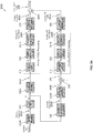
- FIG. 3A is a block diagram of an exemplary process of a first embodiment for creating a STORM signal, according to some embodiments of the present invention.
- An exemplary process 300A may be executed by a processor such as the processor(s) 110 of a transmitter such as the transmitter 102 transmitting an output signal to a receiver such as the receiver 104 in a system such as the system 100.
- the process 300A may be applied for generating a STORM signal compliant with one or more of a plurality of radio access physical layer specifications, for example, based on FDM, DFT-s-OFDM, SC-FDM, FDMA and/or the like.
- the process 300A extends a POSC process such as the process 200C and is applied to a primary sequence ⁇ a n ⁇ 250A such as the sequence of modulation symbols ⁇ a n ⁇ 250 mapping coded data, and an auxiliary sequence of modulation symbols ⁇ b n ⁇ 250B created from the primary sequence ⁇ a n ⁇ 250A.
- the extended POSC process is applied to the primary sequence ⁇ a n ⁇ 250A to generate a primary FD POSC signal s 1 260A such as the FD POSC signal s 260, and to the auxiliary sequence ⁇ b n ⁇ 250B to generate an auxiliary FD POSC signal s 2 260B such as the FD POSC signal s 260.
- the process 300A may be applied to constellations of high order, the process 300A is presented for BPSK modulation hence the primary sequence ⁇ a n ⁇ 250A is created by the processor(s) 110 applying a BPSK mapping 202A to the input coded bit stream.
- the processor(s) 110 may apply an auxiliary sequence generation 302 to the primary sequence ⁇ a n ⁇ 250A in order to create the auxiliary sequence ⁇ b n ⁇ 250B.
- the processor(s) 110 may cyclically extend a plurality of finite sub-sequences of M consecutive symbols of the primary sequence ⁇ a n ⁇ 250A to create a plurality of respective finite sub-sequences of consecutive symbols of the auxiliary sequence. This may allow creating b 0 from a 0 , a M -1 , and a M -2 and creating b 1 from a 1 , a 0 , and a M -1 in the example under consideration.
- the processor(s) 110 applies to both the primary sequence ⁇ a n ⁇ 250A and the auxiliary sequence ⁇ b n ⁇ 250B the phase rotation 220, which for the process 300A may be ⁇ 2 phase rotations 220A and 220B, respectively, as BPSK is used for mapping the primary sequence ⁇ a n ⁇ 250A.
- the outcome of the phase rotations 220A and 220B are a phase rotated primary sequence ⁇ ⁇ n ⁇ 255A and a phase rotated auxiliary sequence ⁇ b ⁇ n ⁇ 255B, respectively, that are driven to their respective DFT modules 218 to create an FD primary sequence ⁇ A k ⁇ and an FD auxiliary sequence ⁇ B k ⁇ , respectively.
- the processor(s) 110 may apply an additional phase shift 304 to apply an additional overall relative phase shift of ⁇ 2 (namely a relative factor of j) to the modulation symbols of the rotated auxiliary sequence ⁇ b ⁇ n ⁇ 255B to create a shifted auxiliary sequence ⁇ b ⁇ n ⁇ 257 that is driven into the respective DFT 218.
- an additional phase shift 304 to apply an additional overall relative phase shift of ⁇ 2 (namely a relative factor of j) to the modulation symbols of the rotated auxiliary sequence ⁇ b ⁇ n ⁇ 255B to create a shifted auxiliary sequence ⁇ b ⁇ n ⁇ 257 that is driven into the respective DFT 218.
- the primary FD POSC signal s 1 260A is generated by the processor(s) 110 through a primary POSC modulation process applied to the primary sequence ⁇ a n ⁇ 250A using a pulse shape ⁇ ( t ) constructed using a FD filter g (0) 224A.
- the auxiliary FD POSC signal s 2 260B is generated by the processor(s) 110 through an auxiliary POSC modulation process applied to the auxiliary sequence ⁇ b n ⁇ 250B using a pulse shape ⁇ ( t ) constructed using a FD filter g (1) 224B. Selection and construction of the pulse shapes ⁇ ( t ) and ⁇ ( t ) is described herein after.
- the pulse shapes ⁇ ( t ) and ⁇ ( t ) are assumed to decay fast enough away from 0, within a time interval shorter than 1 2 T g .
- the frequency domain representation of the pulses may be given by the Fourier coefficients g k 0 and g k 1 satisfying (to a relative high accuracy) the relations expressed in equation 5 below.
- the gain of the pulse shape ⁇ ( t ) used by the processor(s) 110 to create the auxiliary POSC signal is significantly smaller, i.e. by at least 10dB, than the gain of the pulse shape ⁇ ( t ) used by the processor(s) 110 to create the primary POSC signal.
- the processor(s) 110 applies an OFDM modulation such as the OFDM modulation 230 to convert each of the primary FD POSC signal s 1 260A and the auxiliary FD POSC signal s 2 to the time domain, creating a primary TD S 1 POSC signal 360A and an auxiliary TD POSC signal S 2 360B.
- the processor(s) 110 may combine (join), for example, through a summation operation (superposition) 306A the primary TD POSC signal S 1 360A and the auxiliary TD POSC signal S 2 360B to create a TD STORM output signal S STORM 365.
- the processor(s) 110 drives the TD STORM output signal S STORM 365 to a D2A such as the D2A 214 to create an analog signal that is fed to one or more PAs such as the PA 114 to be transmitted to the receiver 104.
- S STORM 365 is expressed in equation 6 below.
- the first and second summands in the equation 6 represent the primary POSC signal and the auxiliary POSC signal, respectively (represented in FD by s 1 260A and s 2 260B in the process 300A).
- M is selected to be an integer multiple of 4.
- equations 4 and 6 may be re-written as expressed in equations 7 and 8 respectively.
- the primary POSC signal and the auxiliary POSC signal may complement each other such that when summed together the amplitude constancy of the joined STORM output signal S STORM 365 may be significantly increased, thus reducing its PAPR.
- the transmitter 102 may transmit a Demodulation Reference Signal (DMRS), carrying predefined (known to both transmitter 102 and receiver 104) pilot symbols, in addition to the data carrying signal.
- DMRS Demodulation Reference Signal
- CE Channel Estimation
- the DMRS symbols may also be created using the process 300A with insertion of one or more pre-defined symbols into the primary sequence ⁇ a n ⁇ 250A.
- a STORM output signal such as the STORM output signal S STORM 365 containing the DMRS in addition to the (to be) transmitted data.
- This may serve to avoid and/or reduce performance deterioration through undesirable degradations in CE quality.
- the CE losses in the detection of the generated STORM output signal S STORM 365 may be negligible ( ⁇ 0.2 dB).
- a receiver frontend such as the receiver frontend 116 of receiver 104 converts the received signal into a STORM output baseband signal ( S STORM , up to some additional noise and/or distortion), and transfers it to a signal demodulator such as the signal demodulator 118, typically integrated with the processor(s) 120 of the receiver 104.
- the processor(s) 120 demodulates the received STORM baseband signal to extract the encoded data.
- the processor(s) 120 may disregard the contribution of the auxiliary POSC signal to the STORM signal and process the received STORM signal as it was a plain POSC signal.
- the processor(s) 120 may use the DMRS symbols embedded in the STORM output signal S STORM 365 to demodulate the received STORM signal.
- the process 300A for generating the STORM output signal S STORM 365 is modified with one or more modifications, for example, adding, removing, adapting and/or unifying one or more steps of the process 300A.
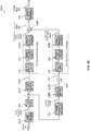
- FIG. 3B is a block diagram of an exemplary process of a second embodiment for creating a STORM signal, according to some embodiments of the present invention.
- An exemplary process 300B may be executed by the processor(s) 110 of the transmitter 102 transmitting an output signal to the receiver 104 in the system 100.
- the process 300B follows the flow of the process 300A with the exception that combining (joining) the primary POSC signal and the auxiliary POSC signal is done in the frequency domain before applying the OFDM modulation 230.
- the process 300B follows the same flow as the process 300A up to the point where the primary FD POSC signal s 1 260A and the auxiliary FD POSC signal s 2 are generated each through its POSC processing pipe.
- the processor(s) 110 may combine (join), for example, through a summation operation (superposition) 306B the primary FD POSC signal s 1 260A and the auxiliary FD POSC signal s 2 260B to create an FD STORM output signal s STORM 265.
- the FD STORM output signal s STORM 265 is driven to the OFDM modulator 230 generating the TD STORM output signal S STORM 365 that is driven to the D2A 214 to create an analog signal fed to one or more of the PAs 114 to be transmitted to the receiver 104.
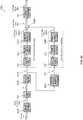
- FIG. 3C is a block diagram of an exemplary process of a third embodiment for creating a STORM signal, according to some embodiments of the present invention.
- An exemplary process 300C may be executed by the processor(s) 110 of the transmitter 102 transmitting an output signal to the receiver 104 in the system 100.
- the process 300C follows the same steps and operations of the process 300B with the exception that the processor(s) 110 applies the alternative auxiliary sequence generation 302A after rotating the primary sequence ⁇ a n ⁇ 250A, thus implementing the mathematical operation expressed in equation 8 instead of the one in equation 4 implemented by the auxiliary sequence generation 302.
- the processor(s) 110 therefore applies an alternative auxiliary sequence generation 302A to the phase rotated primary sequence ⁇ ⁇ n ⁇ 255A to create directly the phase shifted auxiliary sequence ⁇ b ⁇ n ⁇ 257 in the process 300C.
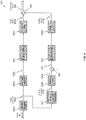
- FIG. 3D is a block diagram of an exemplary process of a fourth embodiment for creating a STORM signal, according to some embodiments of the present invention.
- An exemplary process 300D may be executed the processor(s) 110 of the transmitter 102 transmitting an output signal to the receiver 104 in the system 100.
- the process 300D follows the same steps and operations of the process 300B with some exception, in particular applying a single DFT 218 in the process of generation the FD STORM output signal s STORM 265.
- processor(s) 110 After processor(s) 110 applies the phase rotations 220A and 220B to the primary sequence ⁇ a n ⁇ 250A and the auxiliary sequence ⁇ b n ⁇ 250B, respectively, and after applying the additional phase shift 304 to the rotated auxiliary sequence ⁇ b ⁇ n ⁇ , the processor(s) 110 performs a first partial join operation 306C, for example, a summation operation (superposition) to join the phase rotated primary sequence ⁇ ⁇ n ⁇ 255A and the shifted auxiliary sequence ⁇ b ⁇ n ⁇ 257, and feeds the joined sequence to a single DFT such as the DFT 218 to create a FD joint sequence ⁇ X k ⁇ .
- a first partial join operation 306C for example, a summation operation (superposition) to join the phase rotated primary sequence ⁇ ⁇ n ⁇ 255A and the shifted auxiliary sequence ⁇ b ⁇ n ⁇ 257, and feeds the joined sequence
- the processor(s) 110 may apply a frequency domain split 308 to easily separate the FD joined sequence ⁇ X k ⁇ to the FD primary sequence ⁇ A k ⁇ and the FD auxiliary sequence ⁇ B k ⁇ .
- the frequency domain split 308 may be implemented to derive the FD primary sequence ⁇ A k ⁇ and the FD auxiliary sequence ⁇ B k ⁇ from the FD joined sequence ⁇ X k ⁇ by using, for example, the formulas expressed in equation 9 below.
- a k X k + X M / 2 ⁇ k mod M ⁇ 2
- B k X k ⁇ X M / 2 ⁇ k mod M ⁇ 2
- k 0,1 , ... , M ⁇ 1
- the process 300D proceeds as the process 300B to create the primary FD POSC signal s 1 260A and the auxiliary FD POSC signal s 2 260B using the pulse shapes ⁇ ( t ) and ⁇ ( t ), respectively, constructed with the respective FD filters, filter g (0) 224A and filter g (1) 224B.
- the processor(s) 110 may apply a second partial join operation 306D, for example, a summation operation (superposition), the primary FD POSC signal s 1 260A and the auxiliary FD POSC signal s 2 260B in order to create the FD STORM output signal s STORM 265.
- the single DFT implementation in the process 300D may lead to a more efficient (lower complexity) algorithm for generating the STORM output signal S STORM 365 which in turn may lead to reduced design complexity, reduced computation resources, reduced production complexity and thus to reduced costs and/or power consumption.
- one or more of the modifications applied to the process 300A, 300B, 300C and/or 300D may be combined together to further reduce complexity, computing resources and/or cost of the process for generating the STORM output signal S STORM 365.
- the concept of generating the STORM output signal by joining a primary signal and an auxiliary signal complementing each other to increase amplitude constancy of the output signal, thus reducing its PAPR may be applied to SC (non-FDM) signals processed in the time domain with a time domain implementation of the signals' waveform construction.
- FIG. 4 is a block diagram of an exemplary process for creating an SC-STORM signal, according to some embodiments of the present invention.
- An exemplary process 400 may be executed a processor such as the processor(s) 110 of a transmitter such as the transmitter 102 transmitting an output signal to a receiver such as the receiver 104 in a system such as the system 100.
- the process 400 extends a standard SC generation process with the addition of an auxiliary sequence generation 402, a phase rotation and possible additional phase rotation (shift) to a generated auxiliary sequence and applying pulse shaping constructed with respective filters to a primary sequence and an auxiliary sequence joined together to create an SC-STORM output signal.
- the process 400 may be applied to constellations of high order, the process 400 is presented for BPSK modulation hence the primary sequence ⁇ a n ⁇ 250A is created by the processor(s) 110 applying a BPSK mapping 202A to the input coded bit stream.
- the processor(s) 110 may generate an auxiliary sequence ⁇ b n ⁇ 250B by applying auxiliary sequence generation 402 to the primary sequence ⁇ a n ⁇ 250A.
- the auxiliary sequence generation 402 applies the same design concept of the auxiliary sequence generation 302 presented for the process 300B, the auxiliary sequence generation 402 may be somewhat adjusted since no S/P is applied to the SC signal and hence a cyclic extension of sub-sequences of the primary sequence may not be mandatory.
- the auxiliary sequence generation 402 may generate the auxiliary sequence ⁇ b n ⁇ 250B by applying a formula as expressed in equation 10 below (slightly modified compared to the equation 4).
- the equation 10 is relevant for a very long primary sequence of symbols ⁇ a n ⁇ , with a -1 and a -2 being set to some arbitrary initial values taken from the set ⁇ 1 ⁇ , without affecting the essence of this embodiment.
- b m ⁇ a m a m ⁇ 1 a m ⁇ 2
- m 0 , 1,2 , ...
- the processor(s) 110 applies to both the primary sequence ⁇ a n ⁇ 250A and the auxiliary sequence ⁇ b n ⁇ 250B phase rotation such as the phase rotation 220, for example, a ⁇ 2 phase rotation 220A as BPSK is used for mapping the primary sequence ⁇ a n ⁇ 250A.
- the outcome of the phase rotation 220A is a phase rotated primary sequence ⁇ ⁇ n ⁇ 255A and a phase rotated auxiliary sequence ⁇ b ⁇ n ⁇ 255B.
- the processor(s) 110 may apply an additional phase shift such as the additional phase shift 304 to apply an additional relative overall phase shift (expressed by the multiplicative factor j) to the modulation symbols of the rotated auxiliary sequence ⁇ b ⁇ n ⁇ 255B to create a shifted auxiliary sequence ⁇ b ⁇ n ⁇ 257.
- an additional phase shift such as the additional phase shift 304 to apply an additional relative overall phase shift (expressed by the multiplicative factor j) to the modulation symbols of the rotated auxiliary sequence ⁇ b ⁇ n ⁇ 255B to create a shifted auxiliary sequence ⁇ b ⁇ n ⁇ 257.
- the symbols of the phase rotated primary sequence ⁇ ⁇ n ⁇ 255A may be used to formulate the shifted auxiliary sequence ⁇ b ⁇ n ⁇ 257 as expressed in equation 11 below (slightly modified compared to the equation 8).
- the processor(s) 110 applies up-sampling 404 to the phase rotated primary sequence ⁇ ⁇ n ⁇ 255A and the shifted auxiliary sequence ⁇ b ⁇ n ⁇ 257 before applying pulse shaping onto them, using pulse shapes constructed using a primary filter 406A and an auxiliary filter 406B, respectively, to generate a primary signal S 1 410A and an auxiliary signal S 2 410B.
- Performing the filtering operations 406A and 406B at a higher sampling rate, after up-sampling, is required in order to achieve a desirable accuracy for the selected pulse shapes, which inherently increase the processed signals BW.
- the up-sampling factor is determined according to some tradeoff between accuracy and/or complexity and/or spectral efficiency.
- the processor(s) 110 then combines, for example, through summation 306 the primary signal S 1 410A and an auxiliary signal S 2 410B to generate an SC-STORM output signal S SC-STORM 420.
- the SC-STORM output signal S SC-STORM 420 may be formally expressed through equation 12 below.
- the process 400 may be applied for generating the SC-STORM output signal S SC-STORM 420 created from a primary sequence such as the primary sequence ⁇ a n ⁇ 250A in which fixed sub-sequences of BPSK symbols are embedded, for example, pilot symbols and/or the like.
- the process 400 may be applied to a primary sequence such as the primary sequence ⁇ a n ⁇ 250A embedded with a pre-fixed contiguous sequence of U symbols cyclically inserted within each block
- This implementation may allow the receiver 104 to perform Frequency Domain Equalization (FDE) at the detector, as typically done in OFDM-based receivers while benefiting from the advantages entailed in the STORM process 400, for example, power-efficiency, improved coverage and/or the like.
- FDE Frequency Domain Equalization
- a receiver frontend such as the receiver frontend 116 of receiver 104 converts the received signal into an output baseband signal S SC - STORM 420, up to some additional noise and/or distortion) and transfers it to a signal demodulator such as the signal demodulator 118, typically integrated with the processor(s) 120 of the receiver 104.
- the processor(s) 120 demodulates the received SC-STORM baseband signal to extract the encoded data.
- the processor(s) 120 of the receiver 104 may disregard the contribution of the auxiliary signal S 2 410B and process the received SC-STORM baseband signal as if it were a plain SC signal.
- the processor(s) 120 of the receiver 104 may use the (non-data-carrying) UW symbols embedded in the transmitted SC-STORM signal S SC - STORM 420 to improve its detection.
- the SC-STORM signal may be equivalently generated in the frequency domain, using a process implementation similar to the processes 300A, 300B, 300C and/or 300D.
- FIG. 5 is a block diagram of an exemplary process for creating an SC-STORM signal via frequency domain processing, according to some embodiments of the present invention.
- An exemplary process 500 may be executed by the processor(s) 110 of the transmitter 102 transmitting an output signal to the receiver 104 in the system 100.
- the process 500 is similar to the process 300D with two main exceptions.
- the processor(s) 110 applies a UW insertion 502 to the primary sequence ⁇ a n ⁇ 250A.
- an S/P operation 204A applied onto the primary sequence ⁇ a n ⁇ 250A is assumed to generate sub-sequences (blocks) of M - U symbols.
- the S/P operation 204A is an adaptation of the S/P operation 204 (applied in the process 300D) which generates sub-sequences of M symbols.
- the second modification to the process 500 compared to the process 300D relates to adjusting the OFDM modulation 230 to remove the CP insertion 210, resulting in a modified OFDM modulation 235.
- the processor(s) 110 creates the auxiliary sequence ⁇ b n ⁇ 250B using the formula expressed in the equation 4 as is done in the process 300D.
- the processor(s) 110 applies a DFT such as the DFT 118 to the joined sequence.
- the processor(s) 110 may then split the FD joined sequence by applying the frequency domain split 308 using the formula expressed in the equation 9.
- the design criterion (2) may imply that the design criterion (1) and the design criterion (4) are essentially desirable for the primary FD POSC signal s 1 260A by itself, and not only for the overall STORM output signal S STORM 365.
- the design criterion (4) implies that in order to efficiently generate the STORM output signal S STORM 365, one or more operational characteristics of the PA 114 must be considered with respect to the spectral constraint(s).
- the design criterion (4) expresses some degrees of freedom of the STORM concept, making it adaptable to different communication scenarios and applications, as it involves the one or more operational characteristics of the PA 114, represented, for example, through PA modeling as well as specifying regulatory and/or specification-based spectral constraints.
- a first exemplary method for constructing the pulse shapes ⁇ ( t ) and ⁇ ( t ) in the frequency domain for use in the equation 6 (and/or the equation 7) is based on creating the pulse shapes ⁇ ( t ) and ⁇ ( t ) based on some real symmetric ancestor function p (t).
- the pulse shapes ⁇ ( t ) and ⁇ ( t ) may be constructed by the processor(s) 110 of the transmitter 102 using the FD filters g (0) 224A and g (1) 224B, respectively.
- one or more additional restrictions may be applied.
- an ancestor function p ( t ) which is continuous and sufficiently smooth within its support, and which satisfies the conditions (a) and (b) in equation 16 below.
- the restriction(s) 15, 16(a) and 16(b) may be further appended by another condition as expressed in equation 16(c) below to construct particularly nicely-behaved pulse shapes ⁇ ( t ) and/or ⁇ ( t ).
- a p L T ⁇ 2 1 2
- the pulse shapes ⁇ ( t ) and ⁇ ( t ) may be constructed by the processor(s) 110, and/or prepared in advance in some offline process, using the ancestor function p ( t ) according to the formulas expressed in equation 17 below.
- both (intimately coupled) pulse shapes ⁇ ( t ) and ⁇ ( t ) are also symmetric, each relative to the center of its own support region (pulse duration), as expressed in equation 19 below.
- FIG. 6 is a graph of an exemplary ancestor function used for constructing pulse shapes used to generate a STORM signal, according to some embodiments of the present invention.
- a primary pulse shape ⁇ ( t ) 612 and an auxiliary pulse shape ⁇ ( t ) 614 are generated from an ancestor function p ( t ) 610 such as the ancestor function p 3 ( t ).
- the power of the auxiliary pulse shape ⁇ ( t ) 614 is significantly smaller than the power of the primary pulse shape ⁇ ( t ) 612.
- Equation 22 Another exemplary ancestor function p ( t ) that may be used to generate a STORM output signal such as the STORM output signal S STORM 365, having particularly low PAPR and improved spectral behavior, is presented in equation 22 below.
- p t cos ⁇ 2 ⁇ ⁇ 1 2 L T ⁇ t ⁇ 1 2 L T ⁇ d ⁇ K ⁇ ; ⁇ , 1 2 L T ⁇ , 0 ⁇ t ⁇ L T ⁇
- Q t ⁇ t ⁇ dx 2 ⁇ e ⁇ x 2 / 2 where ⁇ is some positive parameter, and the restrictions expressed in the
- a second exemplary method for constructing the pulse shapes ⁇ ( t ) and ⁇ ( t ) in the frequency domain for use in the equation 6 (and/or the equation 7) is based on deriving the auxiliary pulse shape ⁇ ( t ) directly from the primary pulse shape ⁇ ( t ), without requiring the ancestor function p ( t ).
- the auxiliary pulse shape ⁇ ( t ) may be constructed by the processor(s) 110 of the transmitter 102, and/or prepared in advance in some offline process, based on a primary pulse shape ⁇ ( t ) whose support satisfies supp( ⁇ ) ⁇ (- LT ⁇ , T ⁇ ) for some integer L ⁇ 2, by using a formula expressed in equation 23 below.
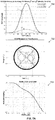
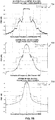
- FIG. 7A and FIG. 7B are graphs presenting results of validation experiments for validating performance of a STORM signal, according to some embodiments of the present invention.
- FIG. 7A presents graphs of a spectral representation of a primary and an auxiliary pulse shapes used to create a STORM signal used for validation experiments, a representation of the resulting STORM signal in the time domain, and the resulting PAPR performance.
- FIG. 7B presents graphs of comparison results of experiments conducted to validate performance of a STORM signal, according to some embodiments of the present invention.
- the power of an auxiliary pulse shape ⁇ ( t ) 712 is -17 dB below the power of a primary pulse shape ⁇ ( t ) 710.
- a STORM signal generated by superposition of the auxiliary pulse shape ⁇ ( t ) 712 and the primary pulse shape ⁇ ( t ) 710 exhibits the near-constant modulus property in which the amplitude is near constant for the vast majority of time samples, hence the PAPR may be very small.
- the dots inside the unit circle in the graph 702 are due to the CP windowing, namely they represent the (relatively few) samples within the tailored boundaries between consecutive OFDM symbols.
- a graph 703 presents results of a PAPR measurement of the STORM signal, whose time domain behavior is presented in the graph 702, in the form of the Complementary Cumulative Distribution Function (CCDF) of the observed PAPR values over a multitude of time segments of the STORM signal.
- CCDF Complementary Cumulative Distribution Function
- the STORM signal presents a significant output power advantage, namely ⁇ 6.4dB and ⁇ 2.2dB gains relative to SC-FDM and OQPSK-POSC, respectively.
- the STORM output signal S STORM 365 may suffer from some (controlled) ISI that may result in some detection loss at a receiver such as the receiver 104.
- the detection performance was evaluated when deploying a low-complexity (8-state, for BPSK) BCJR demodulator, for generating soft bits at the input to a decoder implemented, for example, in processor(s) 120 in the receiver 104.
- the detection loss at the receiver 104 due to the ISI turned out to be much smaller than the gain in output power (reduced PA OBO).
- the total gain of the STORM signal in Additive White Gaussian Noise (AWGN) channel, with a receiver 104 that ignores the auxiliary POSC signal ( s 2 260B in FD or S 2 360B in TD) is presented in Table 1 below.
- the table 1 presents a comparison of the three signals - the SC-FDM, the OQPSK-POSC and the STORM signal, where all signals are configured to deliver the same throughput.
- the detection loss is defined as the offset in the required Rx Signal-to-Noise Ratio (SNR) for maintaining Block Error Rate (BLER) of 10%, using Turbo channel coding as specified in 3GPP TS 36.212 V13.0.0 (2015-12), Evolved Universal Terrestrial Radio Access (E-UTRA); Multiplexing and channel coding (Release 13) .
- SNR Signal-to-Noise Ratio
- BLER Block Error Rate
- the processes 300A, 300B, 300C and/or 300D for generating the STORM output signal S STORM 365 may be extended to join the primary FD POSC signal s 1 260A with a plurality of R auxiliary FD POSC signals s 2_1 260B_1 through s 2_ R 260B_R (R ⁇ 2). This may allow higher flexibility and/or granularity in complementing the primary FD POSC signal s 1 260A with a plurality of auxiliary FD POSC signals s 2_1 260B_1 through s 2_ R 260B R to further reduce the PAPR of the overall STORM output signal S STORM 365.
- This implementation may also serve to generate the STORM output signal S STORM 365 for (symbol) constellations (modulation schemes) of order greater than 2, i.e. higher than BPSK. While extending the processes 300A, 300B, 300C and/or 300D may entail cost and/or complexity increase, it may provide the advantages of lower PAPR and/or higher spectral efficiency that may be desired for one or more applications.
- FIG. 8 is a block diagram of an exemplary process for creating a STORM signal with a plurality of auxiliary signals, according to some embodiments of the present invention.
- An exemplary process 800 may be executed by a processor such as the processor(s) 110 of a processor such as the transmitter 102 transmitting an output signal to a receiver such as the receiver 104 in a system such as the system 100.
- the process 800 is an extension of the process 300C in which the plurality (R) of auxiliary FD POSC signals s 2_1 260B_1 through s 2_ R 260B_R are combined (joined) with the primary FD POSC signal s 1 260A to create the STORM output signal S STORM 365.
- the process 800 may support high order modulation schemes
- the exemplary process 800 and supporting mathematical description is provided for BPSK mapping 202A.
- the processor(s) 110 may apply an extended auxiliary sequence generation 802 to the phase rotated primary sequence ⁇ ⁇ n ⁇ 255A in order to create a plurality of shifted auxiliary sequences ⁇ b ⁇ r 1 ,n ⁇ 257_1 through ⁇ b ⁇ r R ,n ⁇ 257_R.
- the extended auxiliary sequence generation 802 may be an extension of an auxiliary sequence generation operation such as the alternative auxiliary sequence generation operation 302A.
- the extended auxiliary sequence generation 802 may produce each of the shifted auxiliary sequences ⁇ b ⁇ r 1 , n ⁇ 257_1 through ⁇ b ⁇ r R ,n ⁇ 257_R depending in a specific manner on the symbols of the rotated primary sequence ⁇ ⁇ n ⁇ .
- the processor(s) 110 may apply the DFT 218 to each of the shifted auxiliary sequences ⁇ b ⁇ r 1 , n ⁇ 257_1 through ⁇ b ⁇ r R ,n ⁇ 257_R to create a plurality of FD auxiliary sequences ⁇ B r 1 , k ⁇ through ⁇ B r R ,k ⁇ , respectively.
- the processor(s) 110 may apply the cyclic extension 222 to each of the FD auxiliary sequences ⁇ B r 1 ,k ⁇ through ⁇ B r R ,k ⁇ .
- the processor(s) 110 then may apply a plurality of pulse shapes constructed using a plurality of FD filters g ( r 1 ) 224B_1 through g ( r R ) 224B_R to the plurality of FD auxiliary sequences ⁇ B r 1 , k ⁇ through ⁇ B r R , k ⁇ to create a plurality of auxiliary FD POSC signals s 2_1 260B_1 through s 2_ R 260B_R, respectively.
- the processor(s) 110 combines, for example, through summation operation 306B, the primary FD POSC signal s 1 260A with the plurality of auxiliary FD POSC signals s 2_1 260B_1 through s 2_ R 260B_R to create the FD STORM output signal s STORM 265, which may then be processed by OFDM modulation 230 to generate the TD STORM output signal S STORM 365 to be transmitted.
- TD STORM output signal S STORM 365 is expressed in equation 24 below.
- the equation 24 presents the general expression for the TD STORM output signal S STORM 365.
- Each of the shifted auxiliary sequence ⁇ b ⁇ r,n ⁇ 257B may be created by the processor(s) 110 applying the extended auxiliary sequence generation 802 as expressed in equation 25 below, which is a generalization of the equation 8.
- the binary variables d r,m ⁇ ⁇ 0,1 ⁇ are (uniquely) defined in terms of the binary representation of r as expressed in equation 26 below.
- r ⁇ m + 1 L ⁇ 1 2 m ⁇ 1 d r , m
- the ancestor function p ( t ) complies with the conditions expressed in the equation 15 and optionally, one or more of the additional restrictions as expressed in the equation 16 (a), (b) and/or (c).
- the primary pulse shape ⁇ ( t ) and the auxiliary pulse shapes ⁇ r i ( t ) are created according to a generalization of the equation 17 as expressed in equation 27 below.
- the primary shape ⁇ ( t ) and the auxiliary pulse shapes ⁇ r i ( t ) are created according to a generalization of the equation 23 as expressed in equation 28 below.
- ⁇ r max m 1 ⁇ m ⁇ L ⁇ 1 d r , m ⁇ 0 .
- the equation 14 is generalized such that the power of the auxiliary pulse shape ⁇ ( t ) in the equation 14 is replaced by the sum of the plurality of the auxiliary pulse shapes ⁇ r i ( t ) as expressed in equation 29 below.
- auxiliary pulse shapes ⁇ r i ( t ) with smaller values of r i are expected to be more dominant, and so their inclusion in the design of the STORM output signal S STORM 365 is more likely to benefit the communication system 100 via coverage extension.
- the process 800 involves R + 1 DFT operations 218 (reaching a maximum of 2 L -1 in the extreme case of including all possible 2 L -1 - 1 auxiliary pulse shapes ⁇ r i ( t ) in the generation of the STORM output signal S STORM 365.
- This complexity-reduction aspect may affect the decision of whether or not to include a certain additional auxiliary FD POSC signal s 2_ i in the design if its symbol sequence is orthogonal to that of another unpaired auxiliary FD POSC signal s 2_ i which is already included in the set of auxiliary FD POSC signal s 2_ i , so that the addition would less significantly increase the complexity of the transmitter 102 and thus its inclusion may be considered more favorably.
- extending the STORM methods to include multiple auxiliary signals may also apply to the SC signals construction (in both the time domain and the frequency domain) by extending the expression of the SC-STORM output signal S SC - STORM 420 as expressed in the equation 12 (generated through the process 400 or process 500) to a plurality of auxiliary signals as is described above for the STORM output signal S STORM 365.
- Applying the process 800 to generate the S STORM signal and/or the S SC - STORM signal using the plurality of auxiliary signals may be applied to support higher-order constellations (beyond BPSK) for mapping the data stream into the primary sequence ⁇ a n ⁇ .
- a BPSK mapping such as the BPSK mapping 202A may be extended into a more general Phase Shift Keying (PSK) mapping, for example, a QPSK mapping, an 8PSK mapping and/or the like.
- PSK Phase Shift Keying
- the general PSK mapping may further include mapping the modulation symbols in a differential manner, with (finite-length) memory.
- a complex phase rotation such as the phase rotation 220A may be extended into a more general phase rotation, for example, by a fraction, not necessarily 1 2 , of ⁇ .
- one or more of the STORM signal generation processes 300A, 300B, 300C, 300D, 400, 500 and/or 800 may be extended to support a multiple PA HF transmitter such as the transmitter 102 comprising a plurality of PAs such as the PA 114, for example, 4 or 8 or 16 PAs 114.
- each of the PAs 114 may be of limited power
- the plurality of PAs 114 may be used to simultaneously transmit a respective one of a plurality of partial STORM signals that constitute together the overall STORM signal such that the power of the overall STORM signal is divided among the plurality of PAs 114, each one operating with a relatively small OBO, taking advantage of the respective law-PAPR partial STORM waveform fed into it.
- the plurality of partial STORM signals may be spatially multiplexed and transmitted by, for example, a HF Multiple Input Multiple Output (MIMO) transmitter 102 comprising the plurality of PAs 114, each providing a separate HF transmission path and each fed with one of the plurality of low-PAPR partial STORM signals.
- MIMO Multiple Input Multiple Output
- This implementation may be of particularly use in case Analog and/or Digital Beam-Forming (BF), so called Hybrid BF (HBF), is deployed by both the transmitter 102 and a receiver such as the receiver 104 in a system such as the system 100, and where the HF MIMO channel essentially degenerates into a set of nearly disjoint Single Input Multiple Output (SIMO) channels with low delay spreads.
- BF Analog and/or Digital Beam-Forming
- HBF Hybrid BF
- the plurality of partial STORM signals may be multiplexed using frequency multiplexing, optionally with some band-width overlap between successive pairs of the plurality of partial STORM signals, where each of the plurality of partial STORM signals is transmitted from a disjoint subset of PAs 114, so as to increase the overall number of SC-FDM subcarriers exploited for the transmission, yet each PA 114 operating with a relatively small OBO by virtue of the law-PAPR partial STORM waveform fed into it.
- composition or method may include additional ingredients and/or steps, but only if the additional ingredients and/or steps do not materially alter the basic and novel characteristics of the claimed composition or method.
- a compound or “at least one compound” may include a plurality of compounds, including mixtures thereof.
- range format is merely for convenience and brevity and should not be construed as an inflexible limitation on the scope of the invention. Accordingly, the description of a range should be considered to have specifically disclosed all the possible subranges as well as individual numerical values within that range. For example, description of a range such as from 1 to 6 should be considered to have specifically disclosed subranges such as from 1 to 3, from 1 to 4, from 1 to 5, from 2 to 4, from 2 to 6, from 3 to 6 etc., as well as individual numbers within that range, for example, 1, 2, 3, 4, 5, and 6. This applies regardless of the breadth of the range.
Landscapes
- Engineering & Computer Science (AREA)
- Signal Processing (AREA)
- Computer Networks & Wireless Communication (AREA)
- Physics & Mathematics (AREA)
- General Physics & Mathematics (AREA)
- Mathematical Physics (AREA)
- Discrete Mathematics (AREA)
- Pure & Applied Mathematics (AREA)
- Theoretical Computer Science (AREA)
- Mathematical Optimization (AREA)
- Computational Mathematics (AREA)
- Mathematical Analysis (AREA)
- Data Mining & Analysis (AREA)
- Power Engineering (AREA)
- Spectroscopy & Molecular Physics (AREA)
- Algebra (AREA)
- General Engineering & Computer Science (AREA)
- Software Systems (AREA)
- Databases & Information Systems (AREA)
- Transmitters (AREA)
- Synchronisation In Digital Transmission Systems (AREA)
Description
- The present invention, in some embodiments thereof, relates to generating a high frequency (HF) signal having a low Peak to Average Power Ratio (PAPR) and, more specifically, but not exclusively, to generating a low-PAPR HF signal by complementing the signal with one or more auxiliary signals to increase constancy of the signal's amplitude.
- Wireless communication, in particular cellular communication, is rapidly evolving to provide higher performance, for example, increased throughput, improved Band-Width (BW) utilization, enhanced coverage, reduced cost equipment and/or the like.
- The superior behavior of Single-Carrier Frequency Division Multiplexing (SC-FDM) signals, also known as Discrete Fourier Transform spread Orthogonal Frequency Division Multiplexing (DFT-s-OFDM) signals, over OFDM in terms of performance, in particular due to having reduced PAPR, was the main motivation for adopting SC-FDM as the modulation technique for a plurality of applications, for example, the Long Term Evolution (LTE) uplink.
-
EP 1841158 A1 discloses a transmitter for a communication system having high peak-to-average power ratios, including a transmitter for reducing this high ratio by way of a modulation process.US 2005/153675 A1 discloses a power amplification device for improving the efficiency in which an amplifier operates with a signal having a peak-to-average power ratio that is high. - According to an aspect of some embodiments of the present invention there is provided a transmitter, comprising a processor adapted to convert a primary sequence of modulation symbols into a primary signal, using a primary pulse shape, convert an auxiliary sequence of modulation symbols, created from the primary sequence, to an auxiliary signal using an auxiliary pulse shape and create a joint output signal based on the primary signal and on the auxiliary signal, wherein the processor is configured to create the auxiliary sequence from the primary sequence by generating each modulation symbol of the auxiliary sequence from a corresponding modulation symbol of the primary sequence and at least two preceding modulation symbols of the primary sequence.
- According to some embodiments of the invention, the processor is configured to perform at one or more of the following operations to the primary sequence, or to the auxiliary sequence, or to a compounded sequence thereof:
- When the processing is in frequency domain:
- a complex phase shift by π/2 or a multiple thereof;
- a discrete Fourier transformation, DFT;
- a cyclic extension;
- a filter process with information about the primary pulse shape for the primary sequence and/or about the auxiliary pulse shape for the auxiliary sequence; and
- When the processing is in time domain:
- an up-sampling;
- a filter process with information about the primary pulse shape for the primary sequence and/or about the auxiliary pulse shape for the auxiliary sequence.
- Optionally, according to some embodiments of the invention, a plurality of finite sub-sequences of consecutive symbols of the primary sequence are cyclically extended to create a plurality of respective finite sub-sequences of consecutive symbols of the auxiliary sequence.
- According to some embodiments of the invention, the processor is adapted for transmission of the output signal using any one of a group:
- frequency division multiplexing, FDM;
- discrete-Fourier-transform spread orthogonal FDM, DFT-s-OFDM;
- single carrier FDM, SC-FDM;
- According to some embodiments of the invention, the processor is adapted to periodically insert one or more fixed finite sequence of symbols, including a unique word, UW, into the primary sequence.
- According to some embodiments of the invention, the processor is adapted to convert the primary sequence and the auxiliary sequence to frequency domain signals to create the output signal, wherein the resulting frequency domain output signal is converted back to time domain prior to transmission.
- According to some embodiments of the invention, the processor is adapted to periodically insert guard intervals, GIs, into the time domain output signal. The guard intervals include one or more member of: a cyclic prefix (CP), a cyclic postfix, a zero prefix (ZP) and a zero tail (ZT).
- According to some embodiments of the invention, the primary sequence modulation symbols map the data stream according to a Binary-Phase Shift Keying (BPSK) modulation scheme.
- According to some embodiments of the invention, a Peak to Average Power Ratio (PAPR) of the output signal is lower than the PAPR of the primary signal.
- According to some embodiments of the invention, a power of the auxiliary pulse shape used for converting the auxiliary signal is smaller than the power of the primary pulse shape used for converting the primary signal by at least 10dB such that the power of the auxiliary signal is negligible with respect to the power of the primary signal.
- According to some embodiments of the invention, the primary pulse shape and auxiliary pulse shape comply with one or more of a plurality of pulse duration constraints.
- According to some embodiments of the invention, the processor is adapted to create the output signal to comply with at least one of a plurality of signal spectral constraints.
- According to some embodiments of the invention, the primary pulse shape and the auxiliary pulse shape are constructed using an ancestor function.
- According to some embodiments of the invention, the auxiliary pulse shape is based on the primary pulse shape.
- According to some embodiments of the invention, the processor is adapted to perform the superposition in the frequency domain after separately converting the primary sequence and the auxiliary sequence into the frequency and the processor is adapted to join the primary signal and the auxiliary signal through a first partial join in the time domain of the respective primary and auxiliary sequences and a second partial join in the frequency domain.
- According to some embodiments of the invention, the output signal is transmitted simultaneously as a plurality of partial output signals through a plurality of power amplifiers to support a multi input multi output, MIMO, transmission.
- According to some embodiments of the invention, the output signal is transmitted simultaneously as a plurality of partial output signals through a plurality of power amplifiers divided to a plurality of subsets.
- According to some embodiments of the invention, the processor is adapted to create one or more demodulation reference signal similarly to the output signal.
- Another embodiment of the invention relates to a computer program claimed in claim 19.
- Unless otherwise defined, all technical and/or scientific terms used herein have the same meaning as commonly understood by one of ordinary skill in the art to which the invention pertains. Although methods and materials similar or equivalent to those described herein can be used in the practice or testing of embodiments of the invention, exemplary methods and/or materials are described below. In case of conflict, the patent specification, including definitions, will control. In addition, the materials, methods, and examples are illustrative only and are not intended to be necessarily limiting.
- Some embodiments of the invention are herein described, by way of example only, with reference to the accompanying drawings. With specific reference now to the drawings in detail, it is stressed that the particulars shown are by way of example and for purposes of illustrative discussion of embodiments of the invention. In this regard, the description taken with the drawings makes apparent to those skilled in the art how embodiments of the invention may be practiced.
- In the drawings:
-
FIG. 1 is a schematic illustration of an exemplary system for reducing PAPR of an HF signal by complementing the signal with one or more auxiliary signals to increase constancy of the signal's amplitude, according to some embodiments of the present invention; -
FIG. 2A is a block diagram of an exemplary process for creating an OFDM signal; -
FIG. 2B is a block diagram of an exemplary process comprising a DFT for creating a SC-FDM, also known as DFT-s-OFDM, signal; -
FIG. 2C is a block diagram of an exemplary process for creating a PAPR-Optimized SC-FDM (POSC) signal; -
FIG. 3A is a block diagram of an exemplary process of a first embodiment for creating a SynThesis Of a neaR-constant Modulus (STORM) signal, according to some embodiments of the present invention; -
FIG. 3B is a block diagram of an exemplary process of a second embodiment for creating a STORM signal, according to some embodiments of the present invention; -
FIG. 3C is a block diagram of an exemplary process of a third embodiment for creating a STORM signal, according to some embodiments of the present invention; -
FIG. 3D is a block diagram of an exemplary process of a fourth embodiment for creating a STORM signal, according to some embodiments of the present invention; -
FIG. 4 is a block diagram of an exemplary process for creating a Single Carrier (SC) STORM signal, according to some embodiments of the present invention; -
FIG. 5 is a block diagram of an exemplary process for creating an SC-STORM signal via frequency domain processing, according to some embodiments of the present invention; -
FIG. 6 is a graph of an exemplary ancestor function and resulting pulse functions of time used for constructing pulse shapes used to generate a STORM signal, according to some embodiments of the present invention; -
FIG. 7A presents graphs of a spectral representation of a primary and an auxiliary pulse shapes used to create a STORM signal, and a representation of the resulting exemplary STORM signal in the time domain and its PAPR behavior, according to some embodiments of the present invention; -
FIG. 7B presents graphs of comparison results of simulations conducted to evaluate the performance of a STORM signal, according to some embodiments of the present invention; and -
FIG. 8 is a block diagram of an exemplary process for creating a STORM signal with a plurality of auxiliary signals, according to some embodiments of the present invention. - The present invention, in some embodiments thereof, relates to generating a low-PAPR HF signal and, more specifically, but not exclusively, to generating a low-PAPR HF signal by complementing the signal with one or more auxiliary signals to increase constancy of the signal's amplitude.
- The present invention presents devices, systems and methods for generating SynThesis Of a neaR-constant Modulus (STORM) signals exhibiting high amplitude constancy and hence reduced PAPR. The STORM technique may be applied for generating wireless transmission signals compliant with one or more of a plurality of modulation, multiplexing and multiple access (MA) schemes, for example, a Frequency Division Multiplexing (FDM), a Discrete Fourier Transform spread Orthogonal FDM (DFT-s-OFDM), a Single Carrier FDM (SC-FDM), a transmission based on Frequency Division Multiple Access (FDMA) and/or the like utilizing a High Frequency (HF) band, for example, above 6 GHz. The STORM technique may be further applied for generating Single Carrier (SC) signals. The STORM technique is based on generating one or more auxiliary signals that are created from a primary signal carrying a (to be) transmitted data stream. The primary signal is combined with the auxiliary signal(s) that complement the primary signal, where the auxiliary signal(s) rectifies the nonzero PAPR of the primary signal to form the STORM signal having increased amplitude constancy and thus reduced PAPR. In order to efficiently complement each other, the primary and auxiliary signals are generated using carefully selected and/or constructed primary and auxiliary pulse shapes, respectively. Power of the auxiliary pulse shape(s) is significantly smaller than the power of the primary pulse shape, implying that the power of the auxiliary signal is significantly lower than the power of the primary signal.
- To further increase the amplitude constancy of the STORM signal, auxiliary sequences of modulation symbols from which the auxiliary signal(s) are generated comprise modulation symbols which depend on a plurality of respective modulation symbols of a primary sequence from which the primary signal is generated. The primary sequence modulation symbols maps a (to be) transmitted data bit stream in one or more of a plurality of modulation schemes, for example, Binary Phase-shift Keying (BPSK), Quadrature Phase-shift Keying (QPSK), 8 Phase-shift Keying (8PSK) and/or the like.
- The STORM technique may present multiple advantages compared to currently existing systems and/or methods used for reducing the PAPR of wireless transmission signals.
- One of the main problems involved with wireless transmission signals, in particular for OFDM signals, SC-FDM signals, SC signals and/or the like is their relatively high PAPR. The high PAPR implies that the maximum (peak) amplitude may be significantly higher than the mean amplitude of the transmitted signal. The high PAPR forces the transmitted signals to be significantly attenuated before being fed into a non-linear Power Amplifier (PA) of a wireless transmitter. The attenuation is required in order to ensure that the (non-linear) PA is operating in its (near-optimal) operational region and to prevent the PA from entering its saturation region when the amplitude of the (to be) transmitted signal at the PA input is relatively high, thus limiting an undesirable distortion of the transmitted signal. This means that the entire amplitude scale of the transmitted signal may be reduced, due to the required attenuation, such that the maximal amplitude is still within the operational region of the PA. This attenuation is referred to as Input power Back-Off (IBO), resulting in an Output power Back-Off (OBO) of the PA. It is naturally desired to reduce the OBO as much as possible in order to achieve increased gain for the transmitted signal for one or more reasons, for example, increase communication link coverage range, enabling usage of lower efficiency PAs (i.e. cheaper PAs) in the transmitting equipment and/or the like, while still maintaining spectral containment of the transmitted signal.
- To mitigate the PAPR problem of various waveforms, including and particularly OFDM-based waveforms, some of the currently existing methods may apply one or more add-ons to the transmitter (at different digital-baseband processing stages), for example, clipping or companding and filtering (CAF), Tone Reservation (TR), Tone Insertion/Injection (TI), Peak Cancellation, Selective Mapping (SLM), Partial Transmit Sequences (PTS) and Active Constellation Extension (ACE). Some of the currently existing methods may further employ Weighted OverLap & Add (WOLA) and/or filtering (i.e. filtered-OFDM) on the concatenated sequence of OFDM symbols to improve the spectral properties of the overall signal. Although occasionally having only a marginal impact on the PAPR, such processing may allow further reduction in the OBO, which is of particular interest when the transmitted signal should comply with strict requirements on the In-Band Emission (IBE) and/or Out-Of-Band Emission (OOBE), including a constraint defined, for example, in terms of a Spectral Emission Mask (SEM).
- The existing PAPR reduction techniques, present some disadvantages due to tradeoffs between one or more characteristics of the transmitted signal, for example:
- An explicit Spectral Efficiency (SE) loss implied by decreasing the number of data-carrying subcarriers and/or an implicit SE loss due to unavoidable detection losses of the modified waveform of the signal.
- A distortion of the transmitted signal which cannot be compensated at the receiver, thus causing undesired OOBE and/or IBE, the latter being measured in terms of Error Vector Magnitude (EVM).
- An Increased complexity in the design and/or production of the transmitting and/or receiving equipment that may translate to, for example, increased costs, increased power consumption, reduced battery life and/or the like.
- Another approach used by the existing techniques of PAPR reduction of OFDM-based waveforms is to perform a DFT precoding (or spreading) of the modulated Quadrature Amplitude Modulation symbols (QAMs) to process their sequence in the frequency domain before mapping it onto the Inverse Fast Fourier Transform (IFFT) input of the OFDM modulator. This may allow taking advantage of the Frequency Domain Equalization (FDE) of the OFDM signal at the receiver while reducing the PAPR of the signal to be transmitted. However, the filters used in the frequency domain processing at the transmitter may be typically constrained to satisfy the Nyquist criterion in order to avoid introduction of Inter-Symbol Interference (ISI) between the QAMs within each OFDM symbol.
- Application of the STORM technique to SC-FDM-based waveforms may significantly reduce the PAPR of the transmitted signal, thus reducing the OBO of the PA. Consequently, the STORM technique presents a plurality of additional advantages, for example:
- The STORM implementation is based on the SC-FDM modulator with minor modifications hence presenting insignificant complexity increase to the transmitter.
- Using specially crafted pulse shapes for generating the STORM signal allows compliance with requirements of SEM, Adjacent-Carrier Leakage Ratio (ACLR) and EVM
- Since the power of the auxiliary signal is significantly smaller than the power of the primary signal, for example, by 17dB, a receiver receiving the STORM signal may process the STORM signal while ignoring the auxiliary signal, which may be implemented with a small complexity increase relative to a standard SC-FDM receiver.
- Before explaining at least one embodiment of the invention in detail, it is to be understood that the invention is not necessarily limited in its application to the details of construction and the arrangement of the components and/or methods set forth in the following description and/or illustrated in the drawings and/or the Examples. The invention is capable of other embodiments or of being practiced or carried out in various ways.
- The present invention may be a system, a method, and/or a computer program product. The computer program product may include a computer readable storage medium (or media) having computer readable program instructions thereon for causing a processor to carry out aspects of the present invention.
- The computer readable storage medium can be a tangible device that can retain and store instructions for use by an instruction execution device. The computer readable storage medium may be, for example, but is not limited to, an electronic storage device, a magnetic storage device, an optical storage device, an electromagnetic storage device, a semiconductor storage device, or any suitable combination of the foregoing.
- Computer readable program instructions described herein can be downloaded to respective computing/processing devices from a computer readable storage medium or to an external computer or external storage device via a network, for example, the Internet, a local area network, a wide area network and/or a wireless network.
- The computer readable program instructions may execute entirely on the user's computer, partly on the user's computer such as the user equipment (UE), as a stand-alone software package, partly on the user's computer and partly on a remote computer such as the network apparatus or entirely on the remote computer or server. In the latter scenario, the remote computer may be connected to the user's computer through any type of network, including a local area network (LAN) or a wide area network (WAN), or the connection may be made to an external computer (for example, through the Internet using an Internet Service Provider). In some embodiments, electronic circuitry including, for example, programmable logic circuitry, field-programmable gate arrays (FPGA), or programmable logic arrays (PLA) may execute the computer readable program instructions by utilizing state information of the computer readable program instructions to personalize the electronic circuitry, in order to perform aspects of the present invention.
- Aspects of the present invention are described herein with reference to flowchart illustrations and/or block diagrams of methods, apparatus (systems), and computer program products according to embodiments of the invention. It will be understood that each block of the flowchart illustrations and/or block diagrams, and combinations of blocks in the flowchart illustrations and/or block diagrams, can be implemented by computer readable program instructions.
- The flowchart and block diagrams in the Figures illustrate the architecture, functionality, and operation of possible implementations of systems, methods, and computer program products according to various embodiments of the present invention. In this regard, each block in the flowchart or block diagrams may represent a module, segment, or portion of instructions, which comprises one or more executable instructions for implementing the specified logical function(s). In some alternative implementations, the functions noted in the block may occur out of the order noted in the figures. For example, two blocks shown in succession may, in fact, be executed substantially concurrently, or the blocks may sometimes be executed in the reverse order, depending upon the functionality involved. It will also be noted that each block of the block diagrams and/or flowchart illustration, and combinations of blocks in the block diagrams and/or flowchart illustration, can be implemented by special purpose hardware-based systems that perform the specified functions or acts or carry out combinations of special purpose hardware and computer instructions.
- Reference is now made to
FIG. 1 , which is a schematic illustration of an exemplary system for reducing PAPR of an HF signal by complementing the signal with one or more auxiliary signals to increase constancy of the signal's amplitude, according to some embodiments of the present invention. Anexemplary system 100 includes atransmitter 102 transmitting to a receiver 104 a wireless HF signal compliant with one of a plurality of radio access physical layer specifications, for example, based on FDM, DFT-s-OFDM, SC-FDM, FDMA and/or the like in one of a plurality of frequency bands, for example, between 6-100 GHz. The HF signal may be utilized for one or more of a plurality of cellular communication applications, for example, a cellular uplink (UL), a cellular downlink (DL), and/or the like. The HF signal may be further utilized for one or more of a plurality of general wireless applications, for example, a Wireless Local area Network (WLAN) such as, for example, Wi-Fi and/or the like. Typically, but not exclusively, the HF signal is utilized for uplink such that thetransmitter 102 may be integrated in an endpoint device, for example, a cellular user equipment (UE), a WLAN node and/or the like, while thereceiver 104 may typically, but not exclusively, be integrated in a network infrastructure apparatus, for example, a node B, an evolved Node B (eNB), a Base Station (BS) and/or a WLAN Access Point (AP). However, as discussed before, since in some applications the HF may be utilized for downlink and/or general wireless transmission, thetransmitter 102 and/or thereceiver 104 may be integrated in any one or more network apparatuses of the network to be used at either end (uplink, downlink, sidelink, general transmission and/or the like) of the network. - The
transmitter 102 comprises a processor(s) 110 for collecting (receiving) the (to be) transmitted data and generating the transmitted output signal, asignal modulator 112 for modulating the output signal and one or more Power Amplifiers (PA) 114 for transmitting the output signal. Thesignal modulator 112 may be integrated with the processor(s) 110 such that the processor(s) 110 performs the signal modulation. The processor(s) 110 may include one or more processors (homogenous or heterogeneous), which may be arranged for parallel processing, as clusters and/or as one or more multi core processing units. The processor(s) 110 may include one or more co-processors, support hardware processing units, function specific processors and/or the like. For example, the processor(s) 110 may include a Digital Signals Processor (DSP), a communication processor, a hardware signal processing Integrated circuit (IC) and/or the like for creating, modulating and/or adjusting the output signal. The processor(s) 110 may execute one or more software modules for creating, modulating and/or adjusting the output signal. Each of the software module(s) comprises a plurality of program instructions that may be executed by the processor(s) 110 from one or more persistent and/or volatile memory devices, for example, a Read Only Memory (ROM), a Random Access Memory (RAM), a Flash array, a memory card and/or the like. Since typically, thetransmitter 102 is integrated in the end devices that in many application may be a mobile device, the PA(s) 114 are typically smaller, cheaper and more power saving oriented. - The
receiver 104 comprises areceiver 116 for receiving the output signal from thetransmitter 102, asignal demodulator 118 for demodulating the output signal and aprocessor 120 such as the processor(s) 110 for extracting, reconstructing and/or processing the data received in the output signal. Thesignal demodulator 118 may be integrated with the processor(s) 120 such that the processor(s) 120 performs the signal demodulation. The processor(s) 120 execute one or more software modules and/or may use one or more of the co-processors, the support hardware processing units, the function specific processors and/or the like for extracting, reconstructing and/or processing the data received in the output signal. - The
transmitter 102 andreceiver 104 may contain additional components and modules whose roles are irrelevant for the current presentation and are therefore not shown inFIG. 1 for reasons of clarity. - Before further explaining the methods and processes for generating the STORM signal, some general terms, concepts, methods and/or processes for creating OFDM-based signals and/or SC(-FDM)-based signals as known in the art are first described.
- Reference is now made to
FIG. 2A , which is a block diagram of an exemplary process for creating an OFDM signal. Aprocess 200A may be executed by a processor such as the processor(s) 110 of a transmitter such as thetransmitter 102 transmitting an output signal to a receiver such as thereceiver 104 in a system such as thesystem 100. The processor(s) 110 receives a coded bit stream that is to be transmitted and applies Quadrature Amplitude Modulation (QAM)mapping 202 to map the coded bit stream to a sequence of modulation symbols {an } 250. The processor(s) 110 may create the sequence {an } 250 using a plurality of modulation schemes, for example, BPSK, QPSK and/or the like. The processor(s) 110 may apply a serial to parallel (S/P)conversion 204 to the sequence {an } 250 to produce M QAM symbols arranged in parallel to allow further processing in the processor(s) 110. The processor(s) 110 performssubcarrier mapping 206 to map the symbols of the sequence {an } 250 to a plurality of subcarriers according to the specification of the OFDM signal applied in thesystem 100. The processor(s) 110 applies an N-Point Inverse Fast Fourier Transform (IFFT) 208 to convert the sequence to the time domain and inserts a Cyclic Prefix (CP) 210 guard interval between the resulting OFDM symbols in order to reduce the ISI in the generated signal. The guard intervals may include for example, a cyclic prefix (CP), a cyclic postfix, a zero prefix (ZP), a zero tail (ZT) and/or the like. The processor(s) 110 applies a parallel to serial (P/S)conversion 212 to the resulting stream of samples at the output ofCP insertion 210 to produce a serial output data stream. Thesubcarrier mapping 206, theIFFT 208, theCP insertion 210 and the P/S conversion 212 are designated herein after asOFDM modulation 230. The processor(s) 110 then drives the serial output stream of samples to a digital to analog converter (D2A) 214 that converts the output sample stream to an analog signal that is fed to one or more power amplifiers such as thePA 114 for transmission. Other optional operations, such as WOLA (e.g. between theCP insertion 210 and the P/S conversion 212) and/or time domain filtering (e.g. between the P/S conversion 212 and the D2A conversion 214), are omitted fromFIG. 2A for clarity. The generated OFDM signal may be represented as a complex function of time as expressed inequation 1 below (applicable for a time interval containing a single OFDM symbol).


- Since the PAPR of the waveform of the generic OFDM signal is typically high, in order to reduce distortions (in-band and/or out-of-band), the gain of the PA(s) 114 may be significantly reduced to prevent the PA(s) 114 from operating in the saturation region, thus leading to a high Output power Back-Off (OBO) at the PA(s) 114. A plurality of techniques are known in the art to overcome the problem by reducing the PAPR of the OFDM signal while benefitting from the Frequency Domain Equalization (FDE) advantage of the OFDM scheme. One of these techniques comprises performing a Discrete Fourier Transform (DFT) precoding (or spreading) of the sequence {an } 250 (modulated QAMs) before mapping the sequence {an } 250 onto the
IFFT 208 as part of theOFDM modulation 230. - Reference is also made to
FIG. 2B , which is a block diagram of an exemplary process comprising a DFT for creating an OFDM-based signal, specifically DFT-s-OFDM (or SC-FDM) signal. Aprocess 200B may be executed by the processor(s) 110 of thetransmitter 102 transmitting an output signal to thereceiver 104 in thesystem 100. Theprocess 200B is similar to theprocess 200A (including theD2A 214 and the PA(s) 114), with the addition that prior to applying the OFDM modulation the processor(s) 110 applies an M -Point DFT 218 to the sequence {an } 250, after S/P 204, to create a Frequency Domain (FD) sequence of symbols {Ak }, thus forming an SC-FDM modulation scheme 200B. The size M of theDFT 218 is set to be sufficiently smaller than the size N of theIFFT 208. The resulting output signal as expressed inequation 2 below is referred to as DFT-s-OFDM, or Single-Carrier FDM (SC-FDM), as it is essentially an interpolated SC signal up to the CP insertion.
- To ensure the interpolative nature of the combined operation of
DFT 218 followed by theIFFT 208, thus ensuring reduced PAPR of the resulting signal, the bin-mapping operation of the M outputs from theDFT 218 must be equal-spaced, e.g., perform thesubcarrier mapping 206 onto M contiguous subcarriers during theOFDM modulation 230. - In order to further reduce the PAPR and consequently reduce the OBO of the PA(s) 114, one or more additional techniques, methods and/or processes may be applied to the
process 200A (for creating the OFDM signal) and/or theprocess 200B (for creating the SC-FDM signal) as known in the art. These additional methods may include, for example, complex phase rotation between consecutive QAM symbols, for example, rotation of

- Reference is also made to
FIG. 2C , which is a block diagram of an exemplary process for creating a POSC signal. Aprocess 200C may be executed by the processor(s) 110 of thetransmitter 102 transmitting an output signal to thereceiver 104 in thesystem 100. Theprocess 200C adds some additional steps to theprocess 200B, in particular, anoptional phase rotation 220 and a POSC modulation process comprising the SC-FDM modulation 232 with the addition of acyclic extension 222 and aFD filter g 224. Naturally theprocess 200C comprises theD2A 214 and the PA(s) 114 (even though not present inFIG. 2C ). In case thephase rotation 220 is applied to the sequence {an } 250 the resulting phase rotatedsequence ã n 255 is injected to theDFT 218 to create an FD sequence {Ak }. The processor(s) 110 applies the spectralshaping filter g 224, for example, using FD PAPR Reduction Filter (PRF) taps gk to create a pulse shape applied to the FD sequence {Ak } for generating an FDPOSC signal s 260. The taps gk of thefilter g 224 are typically constrained to satisfy the Nyquist zero-ISI criterion, for example, a Root-Raised Cosine (RRC) filter tap applied to create the FD POSC signal s 260 in order to prevent ISI between the M QAMs of the sequence {an } 250. The processor(s) 110 applies the OFDM modulator to the FD POSC signal s 260 to convert the signal back to the time domain (TD) and create a TD POSC output signal S 360 (SPOSC ) as expressed inequation 3 below.
- As a special case of POSC, when
QAM mapping 202 inFIG. 2C degenerates into Pulse Amplitude Modulation (PAM) mapping and
phase rotation 220 is performed, the resulting POSC signal is referred to as Offset-QAM (OQAM) POSC, OQPSK-POSC being a particular example. - According to some embodiments of the present invention the PAPR is reduced for a signal such as the POSC signal by creating a STORM signal comprising a primary POSC signal carrying the (to be) transmitted data that is combined with one or more auxiliary POSC signals, such that the joint output signal has an amplitude with increased constancy and hence with significantly reduced PAPR.
- The following description for the STORM signal generation demonstrates BPSK (an ∈ {±1}) mapping for QAM mapping of the sequence {an } 250, however the described STORM signal implementation may be extended to higher order modulation schemes such as QPSK, 8PSK and the like.
- Reference is now made to
FIG. 3A , which is a block diagram of an exemplary process of a first embodiment for creating a STORM signal, according to some embodiments of the present invention. Anexemplary process 300A may be executed by a processor such as the processor(s) 110 of a transmitter such as thetransmitter 102 transmitting an output signal to a receiver such as thereceiver 104 in a system such as thesystem 100. Theprocess 300A may be applied for generating a STORM signal compliant with one or more of a plurality of radio access physical layer specifications, for example, based on FDM, DFT-s-OFDM, SC-FDM, FDMA and/or the like. Theprocess 300A extends a POSC process such as theprocess 200C and is applied to a primary sequence {an } 250A such as the sequence of modulation symbols {an } 250 mapping coded data, and an auxiliary sequence of modulation symbols {bn } 250B created from the primary sequence {an } 250A. The extended POSC process is applied to the primary sequence {an } 250A to generate a primary FD POSC signal s 1 260A such as the FD POSC signal s 260, and to the auxiliary sequence {bn } 250B to generate an auxiliary FD POSC signal s 2 260B such as the FDPOSC signal s 260. While theprocess 300A may be applied to constellations of high order, theprocess 300A is presented for BPSK modulation hence the primary sequence {an } 250A is created by the processor(s) 110 applying aBPSK mapping 202A to the input coded bit stream. - The processor(s) 110 may apply an
auxiliary sequence generation 302 to the primary sequence {an } 250A in order to create the auxiliary sequence {bn } 250B. Theauxiliary sequence generation 302 may be based on creating each of the modulation symbols (bm, m = 0,1, ..., M - 1) of the auxiliary sequence {bn } 250B depending on a series of respective modulation symbols of the primary sequence {an } 250A, for example, 3 consecutive symbols such as, for example, bm (where 2 ≤ m < M) is created from the current primary symbol am and two previous modulation symbols (a m-1 and a m-2) as expressed in equation 4 below. For creating the initial two symbols b 0 and b 1, the processor(s) 110 may cyclically extend a plurality of finite sub-sequences of M consecutive symbols of the primary sequence {an } 250A to create a plurality of respective finite sub-sequences of consecutive symbols of the auxiliary sequence. This may allow creating b 0 from a 0, a M-1 , and a M-2 and creating b 1 from a 1, a 0, and a M-1 in the example under consideration. The resulting cyclic extension procedure is expressed by the modulus operator (mod M) in the equation 4, which formulates the generation of the auxiliary sequence {bn } from the primary sequence {an }.
- The processor(s) 110 applies to both the primary sequence {an } 250A and the auxiliary sequence {bn } 250B the
phase rotation 220, which for theprocess 300A may be
phase rotations phase rotations respective DFT modules 218 to create an FD primary sequence {Ak } and an FD auxiliary sequence {Bk }, respectively. - The processor(s) 110 may apply an
additional phase shift 304 to apply an additional overall relative phase shift of
respective DFT 218. - The primary FD POSC signal s 1 260A is generated by the processor(s) 110 through a primary POSC modulation process applied to the primary sequence {an } 250A using a pulse shape φ(t) constructed using a
FD filter g (0) 224A. The auxiliary FD POSC signal s 2 260B is generated by the processor(s) 110 through an auxiliary POSC modulation process applied to the auxiliary sequence {bn } 250B using a pulse shape ϕ(t) constructed using aFD filter g (1) 224B. Selection and construction of the pulse shapes φ(t) and ϕ(t) is described herein after. - The pulse shapes φ(t) and ϕ(t) are assumed to decay fast enough away from 0, within a time interval shorter than

coefficients 

equation 5 below.
- The gain of the pulse shape ϕ(t) used by the processor(s) 110 to create the auxiliary POSC signal is significantly smaller, i.e. by at least 10dB, than the gain of the pulse shape φ(t) used by the processor(s) 110 to create the primary POSC signal. This naturally results in the auxiliary FD POSC signal s 2 260B having power that is significantly smaller than the power of the primary FD POSC signal s 1 260A, and similarly the auxiliary TD
POSC signal S 2 360B having power that is significantly smaller than the power of the TD POSC signal S 1 360A. - The processor(s) 110 applies an OFDM modulation such as the
OFDM modulation 230 to convert each of the primary FD POSC signal s 1 260A and the auxiliary FD POSC signal s 2 to the time domain, creating a primary TD S 1 POSC signal 360A and an auxiliary TDPOSC signal S 2 360B. The processor(s) 110 may combine (join), for example, through a summation operation (superposition) 306A the primary TD POSC signal S 1 360A and the auxiliary TDPOSC signal S 2 360B to create a TD STORMoutput signal S STORM 365. The processor(s) 110 drives the TD STORMoutput signal S STORM 365 to a D2A such as theD2A 214 to create an analog signal that is fed to one or more PAs such as thePA 114 to be transmitted to thereceiver 104. - The resulting STORM time domain
output signal S STORM 365 is expressed in equation 6 below.
- The first and second summands in the equation 6 represent the primary POSC signal and the auxiliary POSC signal, respectively (represented in FD by s 1 260A and s 2 260B in the
process 300A). Here M is selected to be an integer multiple of 4. - Using the expressions of the phase rotated primary sequence {ãn } 255A and the shifted auxiliary sequence {b̂n } 257, the equations 4 and 6 may be re-written as expressed in equations 7 and 8 respectively.


- By generating the symbols of the auxiliary sequence {bn } 250B as dependent on several respective symbols of the primary sequence {an } 250A and selecting appropriate pulse shapes φ(t) and ϕ(t) for generating the primary POSC signal and the auxiliary POSC signal, respectively, the primary POSC signal and the auxiliary POSC signal (represented in FD by s 1 260A and s 2 260B and in TD by S 1 360A and
S 2 360B, respectively, in theprocess 300A) may complement each other such that when summed together the amplitude constancy of the joined STORMoutput signal S STORM 365 may be significantly increased, thus reducing its PAPR. - In order to be able to detect the transmitted signal at the
receiver 104, where the signal is received after passing through an unknown channel, thetransmitter 102 may transmit a Demodulation Reference Signal (DMRS), carrying predefined (known to bothtransmitter 102 and receiver 104) pilot symbols, in addition to the data carrying signal. The DMRS may be used at thereceiver 104 for Channel Estimation (CE) purposes. In order to maintain the low PAPR property throughout the transmission of the output signal, including the DMRS, the DMRS symbols may also be created using theprocess 300A with insertion of one or more pre-defined symbols into the primary sequence {an } 250A. For example, in an OFDM and/or SC-FDM signal, one or more DMRS symbols may be inserted over one middle OFDM symbol every X OFDM symbols in a slot of consecutive OFDM symbols (for instance X = 7 or 6) to create a STORM output signal such as the STORMoutput signal S STORM 365 containing the DMRS in addition to the (to be) transmitted data. This may serve to avoid and/or reduce performance deterioration through undesirable degradations in CE quality. In channels with a low delay spread, that may be typical for HF transmission, the CE losses in the detection of the generated STORMoutput signal S STORM 365 may be negligible (∼0.2 dB). - On the receiver side, a receiver frontend such as the
receiver frontend 116 ofreceiver 104 converts the received signal into a STORM output baseband signal (SSTORM, up to some additional noise and/or distortion), and transfers it to a signal demodulator such as thesignal demodulator 118, typically integrated with the processor(s) 120 of thereceiver 104. The processor(s) 120 demodulates the received STORM baseband signal to extract the encoded data. Since the main contribution to the power of the STORMoutput signal S STORM 365 originates from the primary TD POSC signal S 1 360A (the power of the primary TD POSC signal S 1 360A being significantly larger than the power of the auxiliary TDPOSC signal S 2 360B), the processor(s) 120 may disregard the contribution of the auxiliary POSC signal to the STORM signal and process the received STORM signal as it was a plain POSC signal. The processor(s) 120 may use the DMRS symbols embedded in the STORMoutput signal S STORM 365 to demodulate the received STORM signal. - Optionally, the
process 300A for generating the STORMoutput signal S STORM 365 is modified with one or more modifications, for example, adding, removing, adapting and/or unifying one or more steps of theprocess 300A. - Reference is also made to
FIG. 3B , which is a block diagram of an exemplary process of a second embodiment for creating a STORM signal, according to some embodiments of the present invention. Anexemplary process 300B may be executed by the processor(s) 110 of thetransmitter 102 transmitting an output signal to thereceiver 104 in thesystem 100. Theprocess 300B follows the flow of theprocess 300A with the exception that combining (joining) the primary POSC signal and the auxiliary POSC signal is done in the frequency domain before applying theOFDM modulation 230. Theprocess 300B follows the same flow as theprocess 300A up to the point where the primary FD POSC signal s 1 260A and the auxiliary FD POSC signal s 2 are generated each through its POSC processing pipe. At that point, the processor(s) 110 may combine (join), for example, through a summation operation (superposition) 306B the primary FD POSC signal s 1 260A and the auxiliary FD POSC signal s 2 260B to create an FD STORMoutput signal s STORM 265. The FD STORM output signal sSTORM 265 is driven to theOFDM modulator 230 generating the TD STORMoutput signal S STORM 365 that is driven to theD2A 214 to create an analog signal fed to one or more of thePAs 114 to be transmitted to thereceiver 104. - Reference is also made to
FIG. 3C , which is a block diagram of an exemplary process of a third embodiment for creating a STORM signal, according to some embodiments of the present invention. Anexemplary process 300C may be executed by the processor(s) 110 of thetransmitter 102 transmitting an output signal to thereceiver 104 in thesystem 100. Theprocess 300C follows the same steps and operations of theprocess 300B with the exception that the processor(s) 110 applies the alternativeauxiliary sequence generation 302A after rotating the primary sequence {an } 250A, thus implementing the mathematical operation expressed in equation 8 instead of the one in equation 4 implemented by theauxiliary sequence generation 302. The processor(s) 110 therefore applies an alternativeauxiliary sequence generation 302A to the phase rotated primary sequence {ãn } 255A to create directly the phase shifted auxiliary sequence {b̂n } 257 in theprocess 300C. - Reference is also made to
FIG. 3D , which is a block diagram of an exemplary process of a fourth embodiment for creating a STORM signal, according to some embodiments of the present invention. Anexemplary process 300D may be executed the processor(s) 110 of thetransmitter 102 transmitting an output signal to thereceiver 104 in thesystem 100. Theprocess 300D follows the same steps and operations of theprocess 300B with some exception, in particular applying asingle DFT 218 in the process of generation the FD STORMoutput signal s STORM 265. After processor(s) 110 applies thephase rotations additional phase shift 304 to the rotated auxiliary sequence {b̃n }, the processor(s) 110 performs a firstpartial join operation 306C, for example, a summation operation (superposition) to join the phase rotated primary sequence {ãn } 255A and the shifted auxiliary sequence {b̂n } 257, and feeds the joined sequence to a single DFT such as theDFT 218 to create a FD joint sequence {Xk }. Since the shifted auxiliary sequence {b̂n } 257 has an overallrelative 

- After splitting the FD joined sequence {Xk }, the
process 300D proceeds as theprocess 300B to create the primary FD POSC signal s 1 260A and the auxiliary FD POSC signal s 2 260B using the pulse shapes φ(t) and ϕ(t), respectively, constructed with the respective FD filters,filter g (0) 224A andfilter g (1) 224B. The processor(s) 110 may apply a secondpartial join operation 306D, for example, a summation operation (superposition), the primary FD POSC signal s 1 260A and the auxiliary FD POSC signal s 2 260B in order to create the FD STORMoutput signal s STORM 265. The single DFT implementation in theprocess 300D may lead to a more efficient (lower complexity) algorithm for generating the STORMoutput signal S STORM 365 which in turn may lead to reduced design complexity, reduced computation resources, reduced production complexity and thus to reduced costs and/or power consumption. - Naturally, one or more of the modifications applied to the
process output signal S STORM 365. - According to some embodiments of the present invention, the concept of generating the STORM output signal by joining a primary signal and an auxiliary signal complementing each other to increase amplitude constancy of the output signal, thus reducing its PAPR, may be applied to SC (non-FDM) signals processed in the time domain with a time domain implementation of the signals' waveform construction.
- Reference is now made to
FIG. 4 , which is a block diagram of an exemplary process for creating an SC-STORM signal, according to some embodiments of the present invention. Anexemplary process 400 may be executed a processor such as the processor(s) 110 of a transmitter such as thetransmitter 102 transmitting an output signal to a receiver such as thereceiver 104 in a system such as thesystem 100. Theprocess 400 extends a standard SC generation process with the addition of anauxiliary sequence generation 402, a phase rotation and possible additional phase rotation (shift) to a generated auxiliary sequence and applying pulse shaping constructed with respective filters to a primary sequence and an auxiliary sequence joined together to create an SC-STORM output signal. - While the
process 400 may be applied to constellations of high order, theprocess 400 is presented for BPSK modulation hence the primary sequence {an } 250A is created by the processor(s) 110 applying aBPSK mapping 202A to the input coded bit stream. The processor(s) 110 may generate an auxiliary sequence {bn } 250B by applyingauxiliary sequence generation 402 to the primary sequence {an } 250A. While theauxiliary sequence generation 402 applies the same design concept of theauxiliary sequence generation 302 presented for theprocess 300B, theauxiliary sequence generation 402 may be somewhat adjusted since no S/P is applied to the SC signal and hence a cyclic extension of sub-sequences of the primary sequence may not be mandatory. Theauxiliary sequence generation 402 may generate the auxiliary sequence {bn } 250B by applying a formula as expressed inequation 10 below (slightly modified compared to the equation 4). Theequation 10 is relevant for a very long primary sequence of symbols {an }, with a -1 and a -2 being set to some arbitrary initial values taken from the set {±1}, without affecting the essence of this embodiment.
- Similarly to what is done in the
process 300A, the processor(s) 110 applies to both the primary sequence {an } 250A and the auxiliary sequence {bn } 250B phase rotation such as thephase rotation 220, for example, a
phase rotation 220A as BPSK is used for mapping the primary sequence {an } 250A. The outcome of thephase rotation 220A is a phase rotated primary sequence {ãn } 255A and a phase rotated auxiliary sequence {b̃n } 255B. The processor(s) 110 may apply an additional phase shift such as theadditional phase shift 304 to apply an additional relative overall phase shift (expressed by the multiplicative factor j) to the modulation symbols of the rotated auxiliary sequence {b̃n } 255B to create a shifted auxiliary sequence {b̂n } 257. - Similarly to the equation 8, the symbols of the phase rotated primary sequence {ãn } 255A may be used to formulate the shifted auxiliary sequence {b̂n } 257 as expressed in
equation 11 below (slightly modified compared to the equation 8). In the equation 8, ã -1 and ã -2 can be set to arbitrary initial values from the set {±1, ±j}, yet satisfying the constraint Re(ã -1 ã -2) = 0, without affecting the essence of this embodiment.
- The processor(s) 110 applies up-sampling 404 to the phase rotated primary sequence {ãn } 255A and the shifted auxiliary sequence {b̂n } 257 before applying pulse shaping onto them, using pulse shapes constructed using a
primary filter 406A and anauxiliary filter 406B, respectively, to generate aprimary signal S 1 410A and anauxiliary signal S 2 410B. Performing thefiltering operations summation 306 theprimary signal S 1 410A and anauxiliary signal S 2 410B to generate an SC-STORMoutput signal S SC-STORM 420. - The resulting SC-STORM
output signal S SC-STORM 420 may be expressed by a noncyclic variant of the expression in equation 6, with no insertion of a guard interval of a CP type, i.e. Tg = 0, and hence with no WOLA (CP windowing) processing between consecutive OFDM symbols. The SC-STORMoutput signal S SC-STORM 420 may be formally expressed through equation 12 below.
primary filter 406A and theauxiliary filter 406B utilizing digital filters whose coefficients Φm = φ(mTs + δφ ), m = 0,1, ...,Mφ - 1 and Ψm = ϕ(mTs + δϕ ), m = 0,1, ...,Mϕ - 1 may be some sampled (at rate
- The
process 400 may be applied for generating the SC-STORMoutput signal S SC-STORM 420 created from a primary sequence such as the primary sequence {an } 250A in which fixed sub-sequences of BPSK symbols are embedded, for example, pilot symbols and/or the like. In particular, theprocess 400 may be applied to a primary sequence such as the primary sequence {an } 250A embedded with a pre-fixed contiguous sequence of U symbols cyclically inserted within each block
1 -1 , a lm-U2 , a lm-U2 +1 , ..., a lm-1}is a (fixed) Unique Word (UW) of U = U 1 + U 2 (where U 1, U 2 are non-negative integers) symbols, each ∈ {±1} or all zeros, that repeats itself for any block of M symbols. This implementation may allow thereceiver 104 to perform Frequency Domain Equalization (FDE) at the detector, as typically done in OFDM-based receivers while benefiting from the advantages entailed in theSTORM process 400, for example, power-efficiency, improved coverage and/or the like. - On the receiver side, similarly to the detection of a
STORM signal S STORM 365, a receiver frontend such as thereceiver frontend 116 ofreceiver 104 converts the received signal into an outputbaseband signal S SC-STORM 420, up to some additional noise and/or distortion) and transfers it to a signal demodulator such as thesignal demodulator 118, typically integrated with the processor(s) 120 of thereceiver 104. The processor(s) 120 demodulates the received SC-STORM baseband signal to extract the encoded data. Since the main contribution to the power of the SC-STORMoutput signal S SC-STORM 420 originates from theprimary signal S 1 410A (as the power of theprimary signal S 1 410A is significantly larger than the power of theauxiliary signal S 2 410B), the processor(s) 120 of thereceiver 104 may disregard the contribution of theauxiliary signal S 2 410B and process the received SC-STORM baseband signal as if it were a plain SC signal. The processor(s) 120 of thereceiver 104 may use the (non-data-carrying) UW symbols embedded in the transmitted SC-STORM signal S SC-STORM 420 to improve its detection. - In the scenario(s) in which the SC signal is based on the primary sequence {an } 250A embedded with (copies of) the UW, the SC-STORM signal may be equivalently generated in the frequency domain, using a process implementation similar to the
processes - Reference is also made to
FIG. 5 , which is a block diagram of an exemplary process for creating an SC-STORM signal via frequency domain processing, according to some embodiments of the present invention. Anexemplary process 500 may be executed by the processor(s) 110 of thetransmitter 102 transmitting an output signal to thereceiver 104 in thesystem 100. Theprocess 500 is similar to theprocess 300D with two main exceptions. First, the processor(s) 110 applies aUW insertion 502 to the primary sequence {an } 250A. To maintain consistency, an S/P operation 204A applied onto the primary sequence {an } 250A is assumed to generate sub-sequences (blocks) of M - U symbols. The S/P operation 204A is an adaptation of the S/P operation 204 (applied in theprocess 300D) which generates sub-sequences of M symbols. The second modification to theprocess 500 compared to theprocess 300D relates to adjusting theOFDM modulation 230 to remove theCP insertion 210, resulting in a modifiedOFDM modulation 235. The processor(s) 110 creates the auxiliary sequence {bn } 250B using the formula expressed in the equation 4 as is done in theprocess 300D. After performing the firstpartial join 306C, the processor(s) 110 applies a DFT such as theDFT 118 to the joined sequence. The processor(s) 110 may then split the FD joined sequence by applying the frequency domain split 308 using the formula expressed in the equation 9. - In order to maintain smooth transitions between consecutive modulated blocks, the processor(s) 110 may be adapted to perform the
UW insertion 502 by inserting the first U 2 symbols of the UW as a postfix to each block of M - U data symbols following the S/P 204A, while inserting the remaining last U 1 symbols as a prefix to each block. Furthermore, beyond satisfying U 1 + U 2 = U, both U 1 and U 2 must be sufficiently larger than L, which is the ISI length in units of T̃ introduced by the FD pulse shaping filters g (i=0,1) . - As discussed above for both generation of the STORM
output signal S STORM 365 as well as the SC-STORMoutput signal S SC-STORM 420, selection and/or construction of appropriate pulse shapes φ(t) and ϕ(t) used to create the primary and the auxiliary POSC signals, respectively, has a crucial impact on the resulting signals with respect to constant amplitude and hence reduced PAPR of the output signals. This means that the FD filtersg (0) 224A and g (1) 224Bfor the SC STORM signals and/or the TD filters 406A and 406B for the SC-STORM signals need to be properly selected. - When constructing the pulse shapes φ(t) and ϕ(t), for example, in the frequency domain, to be used with the equation 6 (and/or the equation 7), several design criteria may be followed to achieve range extension of the
communication system 100, in addition to spectral containment and the near-constant amplitude and hence reduced PAPR for the STORM output signal SSTORM 365: - (1) The PAPR of the overall STORM waveform as expressed in the equation 6 (and respectively in the equation 7) should be very small. Formally this may be expressed through equation 13 below.

- (2) The power of the pulse shape ϕ(t) used to create the auxiliary TD
POSC signal S 2 360B should be much smaller than the power of the pulse shape φ(t) used to create the primary TD POSC signal S 1 360A. Formally this may be expressed throughequation 14 below.
- (3) One or more pulse duration constraints (time support) may be applied to the pulse shape φ(t) and/or the pulse shape ϕ(t) (in units of the basic SC-FDM signaling interval T̃ =

receiver 104. - (4) One or more spectral constraints may be applied to the STORM
output signal S STORM 365. For example, the Power Spectral Density (PSD) of the STORMoutput signal S STORM 365 should be sufficiently "narrow", constrained, for example, by a spectral requirement of Spectral Emission Mask (SEM) and/or Adjacent-Carrier Leakage Ratio (ACLR), after passing through a (non-linear) PA such as thePA 114, with as small OBO as possible. - The design criterion (2) may imply that the design criterion (1) and the design criterion (4) are essentially desirable for the primary FD POSC signal s 1 260A by itself, and not only for the overall STORM
output signal S STORM 365. - The design criterion (4) implies that in order to efficiently generate the STORM
output signal S STORM 365, one or more operational characteristics of thePA 114 must be considered with respect to the spectral constraint(s). Hence the design criterion (4) expresses some degrees of freedom of the STORM concept, making it adaptable to different communication scenarios and applications, as it involves the one or more operational characteristics of thePA 114, represented, for example, through PA modeling as well as specifying regulatory and/or specification-based spectral constraints. - A first exemplary method for constructing the pulse shapes φ(t) and ϕ(t) in the frequency domain for use in the equation 6 (and/or the equation 7) is based on creating the pulse shapes φ(t) and ϕ(t) based on some real symmetric ancestor function p(t). The pulse shapes φ(t) and ϕ(t) may be constructed by the processor(s) 110 of the
transmitter 102 using the FD filtersg (0) 224A andg (1) 224B, respectively. The range in which the ancestor function p(t) does not vanish, namely the support (denoted supp(p)) of the function p(t), is between -LT̃ and +LT̃, where
equation 15 below.
- To further facilitate fulfilment of one or more of the design criteria (1-4), one or more additional restrictions may be applied. For example, it is preferable to choose an ancestor function p(t) which is continuous and sufficiently smooth within its support, and which satisfies the conditions (a) and (b) in equation 16 below. The restriction(s) 15, 16(a) and 16(b) may be further appended by another condition as expressed in equation 16(c) below to construct particularly nicely-behaved pulse shapes φ(t) and/or ϕ(t).

- The pulse shapes φ(t) and ϕ(t) may be constructed by the processor(s) 110, and/or prepared in advance in some offline process, using the ancestor function p(t) according to the formulas expressed in equation 17 below.

- It should be noted that due to the restricted support specified above for the ancestor function p(t), the resulting support in time of the pulse shape functions φ(t) and ϕ(t) is given by equation 18 below.

- As is evident from the equation 18, the auxiliary pulse shape ϕ(t) is narrower in time domain (having shorter pulse duration) than the primary pulse shape φ(t), and therefore the
auxiliary filter g (1) 224B is required to be wider in frequency domain than theprimary filter g (0) 224A. Furthermore, by virtue of the symmetry (around 0) of the ancestor function p(t), both (intimately coupled) pulse shapes φ(t) and ϕ(t) are also symmetric, each relative to the center of its own support region (pulse duration), as expressed in equation 19 below.
- The ancestor function p(t) may be selected from a plurality of functions. Some exemplary ancestor functions p(t) are provided in equation 20 below, however other functions may be selected as well for representing the ancestor function p(t). The exemplary ancestor functions p(t) are specified in the equation 20 in the range of 0 ≤ t ≤ LT̃, and their values for negative values of t are determined by exploiting the symmetry relation p(-t) = p(t).

- Using, for example, the ancestor function p 3(t) that satisfies the additional restrictions of the equation 16 and setting L = 2, the constructed pulse shapes φ(t) and ϕ(t) are expressed in equation 21 below.
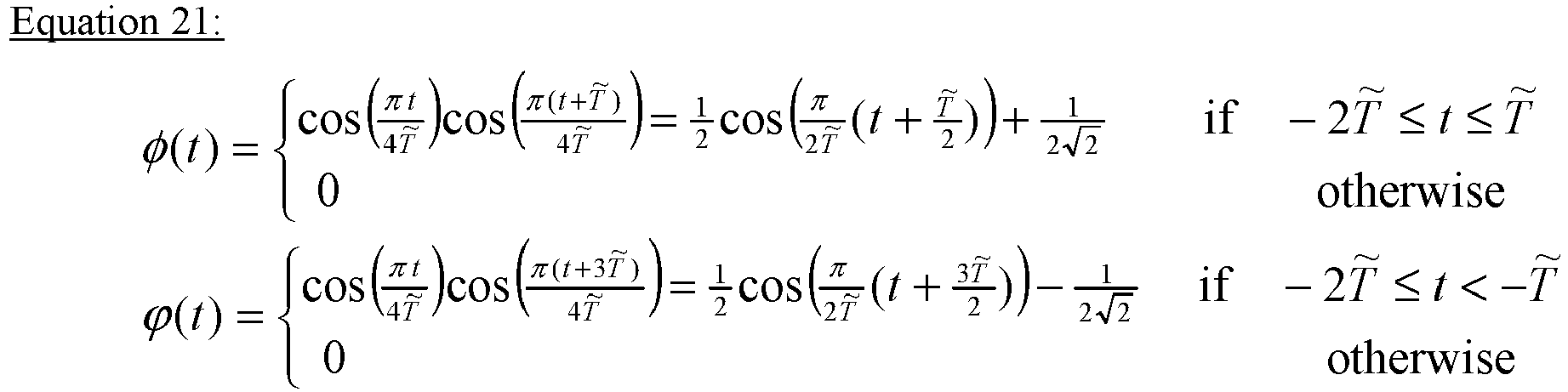
- Reference is now made to
FIG. 6 , which is a graph of an exemplary ancestor function used for constructing pulse shapes used to generate a STORM signal, according to some embodiments of the present invention. As shown in a graph 600 a primary pulse shape φ(t) 612 and an auxiliary pulse shape ϕ(t) 614 are generated from an ancestor function p(t) 610 such as the ancestor function p 3(t). As evident from thegraph 600 the power of the auxiliary pulse shape ϕ(t) 614 is significantly smaller than the power of the primary pulse shape φ(t) 612. - Another exemplary ancestor function p(t) that may be used to generate a STORM output signal such as the STORM
output signal S STORM 365, having particularly low PAPR and improved spectral behavior, is presented in equation 22 below.
- A second exemplary method for constructing the pulse shapes φ(t) and ϕ(t) in the frequency domain for use in the equation 6 (and/or the equation 7) is based on deriving the auxiliary pulse shape ϕ(t) directly from the primary pulse shape φ(t), without requiring the ancestor function p(t). The auxiliary pulse shape ϕ(t) may be constructed by the processor(s) 110 of the
transmitter 102, and/or prepared in advance in some offline process, based on a primary pulse shape φ(t) whose support satisfies supp(φ) ⊆ (-LT̃, T̃) for some integer L ≥ 2, by using a formula expressed in equation 23 below.
- The primary pulse shape φ(t) may not be completely arbitrary, and must satisfy at least the
symmetry constraint 
output signal S STORM 365, the primary pulse shape φ(t) should be continuous and sufficiently smooth, and if it has zeros within its support region, namely there exist discrete values ti ∈ (-LT̃, T̃) s. t. φ(ti ) = 0, then the ti must be arranged T̃ apart from one another and in such a manner that the limit in the equation 23 exists. This implies certain constraints on the derivatives of the primary pulse shape φ(t) at the zero(s) ti , and possibly also at the support boundaries. To satisfy the desirable properties summarized by the design criteria (1-4) of the construction of the primary and auxiliary pulse shapes φ(t) and ϕ(t), further judicious selection of the specific form of the primary pulse shape φ(t) may be applied. However, such restrictions are not mandatory. - The filter coefficients

equation 5 are satisfied with minimal deviations due to finite numerical accuracy and truncation effects, for example, stemming from the fact that in practice Q is bounded by the IFFT size N. - In order to validate the proposed systems and methods for generating the STORM signals and evaluate the potential benefits and/or advantages of the STORM implementation, some simulation experiments were conducted. The experiments use a modified RAPP PA model, namely the one specified in 11-09-0296-16-00ad-evaluation-methodology (section 3.2, as well as section 2.2.3 in 11-15-0866-02-00ay-11ay-evaluation-methodology), as part of the methodology agreed by the IEEE 802.11ad/ay task groups for link performance evaluation at 60 GHz. The spectral constraints are based on those agreed by 3GPP for the New Radio (NR) Study Item (cf. the TSG RAN WG1 email discussion "[85-18] PA assumption for NR", June 2016), with simple rescaling adaptation required for the PA model class. LTE OFDM "10 MHz numerology" is assumed, namely that M ≤ 600 where 600 subcarriers occupy 90% of the total system BW.
- Reference is now made to
FIG. 7A andFIG. 7B , which are graphs presenting results of validation experiments for validating performance of a STORM signal, according to some embodiments of the present invention.FIG. 7A presents graphs of a spectral representation of a primary and an auxiliary pulse shapes used to create a STORM signal used for validation experiments, a representation of the resulting STORM signal in the time domain, and the resulting PAPR performance.FIG. 7B presents graphs of comparison results of experiments conducted to validate performance of a STORM signal, according to some embodiments of the present invention. Agraph 700 presents the FD filter coefficients (taps)

graph 702 presents the distribution in the complex plain of the resulting STORM signal samples in the time domain. As expressed in thegraph 700, the power of an auxiliary pulse shape ϕ(t) 712 is -17 dB below the power of a primary pulse shape φ(t) 710. As expressed in thegraph 702, a STORM signal generated by superposition of the auxiliary pulse shape ϕ(t) 712 and the primary pulse shape φ(t) 710 exhibits the near-constant modulus property in which the amplitude is near constant for the vast majority of time samples, hence the PAPR may be very small. The dots inside the unit circle in thegraph 702 are due to the CP windowing, namely they represent the (relatively few) samples within the tailored boundaries between consecutive OFDM symbols. Agraph 703 presents results of a PAPR measurement of the STORM signal, whose time domain behavior is presented in thegraph 702, in the form of the Complementary Cumulative Distribution Function (CCDF) of the observed PAPR values over a multitude of time segments of the STORM signal. As shown ingraphs PA 114 is tuned to the maximum value possible while making sure the corresponding signals at the output of thePA 114 comply with the spectral constraints. Thegraph 704 presents the spectral behavior of an SC-FDM baseline signal (generated with M = 600 and
graph 706 presents the spectral behavior of an OQPSK-POSC signal (generated with M = 300 and QPSK modulation scheme), and thegraph 708 presents the spectral behavior of the STORM signal generated using the auxiliary pulse shape ϕ(t) 712 and the primary pulse shape φ(t) 710. As evident from thegraphs - Since in the STORM implementation a special choice of non-Nyquist pulse shaping is used, particularly for the primary pulse shape φ(t), the STORM
output signal S STORM 365 may suffer from some (controlled) ISI that may result in some detection loss at a receiver such as thereceiver 104. To cope with the ISI (of length ∼4 in the evaluated example), the detection performance was evaluated when deploying a low-complexity (8-state, for BPSK) BCJR demodulator, for generating soft bits at the input to a decoder implemented, for example, in processor(s) 120 in thereceiver 104. The detection loss at thereceiver 104 due to the ISI turned out to be much smaller than the gain in output power (reduced PA OBO). The total gain of the STORM signal in Additive White Gaussian Noise (AWGN) channel, with areceiver 104 that ignores the auxiliary POSC signal (s 2 260B in FD orS 2 360B in TD) is presented in Table 1 below. The table 1 presents a comparison of the three signals - the SC-FDM, the OQPSK-POSC and the STORM signal, where all signals are configured to deliver the same throughput. The detection loss is defined as the offset in the required Rx Signal-to-Noise Ratio (SNR) for maintaining Block Error Rate (BLER) of 10%, using Turbo channel coding as specified in 3GPP TS 36.212 V13.0.0 (2015-12), Evolved Universal Terrestrial Radio Access (E-UTRA); Multiplexing and channel coding (Release 13).Table 1: Signal DFT Size M Turbo Code Rate Output Power [dBm] OBO Gain [dB] Detection Loss Total Gain [dB] SC- FDM 
600 
13.9 0 0 0 OQPSK-POSC with Excess BW 100%300 
18.1 4.2 0 4.2 SC-FDM- STORM 600 
20.3 6.4 0.2 6.2 - In a similar performance analysis, for a higher Modulation Coding Scheme (MCS) of
BPSK rate 
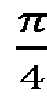
code rate 
- According to some embodiments of the present invention, the
processes output signal S STORM 365 may be extended to join the primary FD POSC signal s 1 260A with a plurality of R auxiliary FD POSC signals s 2_1 260B_1 through s 2_R 260B_R (R ≥ 2). This may allow higher flexibility and/or granularity in complementing the primary FD POSC signal s 1 260A with a plurality of auxiliary FD POSC signals s 2_1 260B_1 through s 2_R 260B R to further reduce the PAPR of the overall STORMoutput signal S STORM 365. This implementation may also serve to generate the STORMoutput signal S STORM 365 for (symbol) constellations (modulation schemes) of order greater than 2, i.e. higher than BPSK. While extending theprocesses - Reference is also made to
FIG. 8 , which is a block diagram of an exemplary process for creating a STORM signal with a plurality of auxiliary signals, according to some embodiments of the present invention. Anexemplary process 800 may be executed by a processor such as the processor(s) 110 of a processor such as thetransmitter 102 transmitting an output signal to a receiver such as thereceiver 104 in a system such as thesystem 100. Theprocess 800 is an extension of theprocess 300C in which the plurality (R) of auxiliary FD POSC signals s 2_1 260B_1 through s 2_R 260B_R are combined (joined) with the primary FD POSC signal s 1 260A to create the STORMoutput signal S STORM 365. - As discussed before for the
processes process 800 may support high order modulation schemes, theexemplary process 800 and supporting mathematical description is provided forBPSK mapping 202A. - The processor(s) 110 may apply an extended
auxiliary sequence generation 802 to the phase rotated primary sequence {ãn } 255A in order to create a plurality of shifted auxiliary sequences {b̂ r1 ,n } 257_1 through {b̂rR ,n } 257_R. The extendedauxiliary sequence generation 802 may be an extension of an auxiliary sequence generation operation such as the alternative auxiliarysequence generation operation 302A. The extendedauxiliary sequence generation 802 may produce each of the shifted auxiliary sequences {b̂ r1 ,n } 257_1 through {b̂rR ,n } 257_R depending in a specific manner on the symbols of the rotated primary sequence {ãn }. The processor(s) 110 may apply theDFT 218 to each of the shifted auxiliary sequences {b̂ r1 ,n } 257_1 through {b̂rR ,n } 257_R to create a plurality of FD auxiliary sequences {B r1 ,k } through {BrR ,k }, respectively. The processor(s) 110 may apply thecyclic extension 222 to each of the FD auxiliary sequences {B r1 ,k } through {BrR ,k }. The processor(s) 110 then may apply a plurality of pulse shapes constructed using a plurality of FD filters g (r1 ) 224B_1 through g (rR ) 224B_R to the plurality of FD auxiliary sequences {B r1 ,k } through {B rR ,k } to create a plurality of auxiliary FD POSC signals s 2_1 260B_1 through s 2_R 260B_R, respectively. The processor(s) 110 combines, for example, throughsummation operation 306B, the primary FD POSC signal s 1 260A with the plurality of auxiliary FD POSC signals s 2_1 260B_1 through s 2_R 260B_R to create the FD STORM output signal sSTORM 265, which may then be processed byOFDM modulation 230 to generate the TD STORMoutput signal S STORM 365 to be transmitted. - The resulting TD STORM
output signal S STORM 365 is expressed in equation 24 below.
- Here R, restricted by 1 ≤ R ≤ 2 L-1, is the number of auxiliary FD POSC signals s 2_1 260B_1 through s 2_R 260B_R that are characterized by (generated using) pulse shaping functions ϕr
i (t), (i = 1,2, ..., R), where

- The equation 24 presents the general expression for the TD STORM
output signal S STORM 365. As evident, the equation 6 is a special case of the equation 8 in which R = 1 and r 1 = 1 (assuming L ≥ 2). - Each of the shifted auxiliary sequence {b̂r,n } 257B may be created by the processor(s) 110 applying the extended
auxiliary sequence generation 802 as expressed in equation 25 below, which is a generalization of the equation 8.


- In an embodiment of the construction of the generalized TD STORM
output signal S STORM 365 as expressed in the equation 24, the primary pulse shape φ(t) and the auxiliary pulse shapes ϕri (t) (i = 1, 2, ... , R) are all generated from a single ancestor function p(t) as described in the first exemplary method for constructing the pulse shapes φ(t) and ϕ(t). The ancestor function p(t) complies with the conditions expressed in theequation 15 and optionally, one or more of the additional restrictions as expressed in the equation 16 (a), (b) and/or (c). The primary pulse shape φ(t) and the auxiliary pulse shapes ϕri (t) are created according to a generalization of the equation 17 as expressed in equation 27 below.
- In another embodiment of the construction of the generalized TD STORM
output signal S STORM 365 as expressed in the equation 24, the auxiliary pulse shapes ϕri (t) (i = 1, 2, ..., R) are generated from the primary pulse shape φ(t) as described in the second exemplary method for constructing the pulse shapes φ(t) and ϕ(t). The primary shape φ(t) and the auxiliary pulse shapes ϕri (t) are created according to a generalization of the equation 23 as expressed in equation 28 below.
- Where

- The specific selection of the primary pulse shape φ(t) and the auxiliary pulse shapes ϕr
i (t) used for generating the primary FD POSC signal s 1 260A and the auxiliary FD POSC signal s 2_i 260B_i (i = 1, 2, ..., R), including the number R and the associated specific set of indices
equation 14 is generalized such that the power of the auxiliary pulse shape ϕ(t) in theequation 14 is replaced by the sum of the plurality of the auxiliary pulse shapes ϕri (t) as expressed in equation 29 below.
- The complexity involved in the inclusion of any additional auxiliary FD POSC signal s 2_i in the design of the TD STORM output signal SSTORM 365 (through the index set

output signal S STORM 365. From this perspective, it may be desirable to include in the set of the auxiliary pulse shapes ϕri (t) at least the first member ϕ 1(t) that is the auxiliary pulse shape with widest support in time (pulse duration), namely select r 1 = 1. In general, the auxiliary pulse shapes ϕri (t) with smaller values of ri are expected to be more dominant, and so their inclusion in the design of the STORMoutput signal S STORM 365 is more likely to benefit thecommunication system 100 via coverage extension. - An implementation of the generalized STORM construction with multiple auxiliary signals in frequency domain as in
process 800 may require generating the R + 1 sets of filter coefficients
blocks 224A, and 224B_1 through 224_R in theFIG. 8 ), respectively, satisfying to within some reasonable accuracy the relations expressed in equation 30 below.
- The
process 800 involves R + 1 DFT operations 218 (reaching a maximum of 2 L-1 in the extreme case of including all possible 2 L-1 - 1 auxiliary pulse shapes ϕri (t) in the generation of the STORMoutput signal S STORM 365. Within the
1 ,n }, ..., {b̂rR ,n } combined viasummation 306B by the processor(s) 110 to create the FD STORM output signal sSTORM 265, it may be possible to find P pairs (where P satisfiesmax 
process 800 form such a pair, since ∀n, Re (ãn ·b̂ 1,n ) = 0 as is evident from the equation 8 (and its generalization, the equation 25). Consequently, theprocess 300D may be generalized for the extended STORM signal, using onlyP DFT operations 218 per SC-FDM symbol. This complexity-reduction aspect may affect the decision of whether or not to include a certain additional auxiliary FD POSC signal s 2_i in the design if its symbol sequence is orthogonal to that of another unpaired auxiliary FD POSC signal s 2_i which is already included in the set of auxiliary FD POSC signal s 2_i , so that the addition would less significantly increase the complexity of thetransmitter 102 and thus its inclusion may be considered more favorably. - The straightforward generalization of the above embodiments, extending the STORM methods to include multiple auxiliary signals may also apply to the SC signals construction (in both the time domain and the frequency domain) by extending the expression of the SC-STORM
output signal S SC-STORM 420 as expressed in the equation 12 (generated through theprocess 400 or process 500) to a plurality of auxiliary signals as is described above for the STORMoutput signal S STORM 365. - Applying the
process 800 to generate the SSTORM signal and/or the S SC-STORM signal using the plurality of auxiliary signals may be applied to support higher-order constellations (beyond BPSK) for mapping the data stream into the primary sequence {an }. In that case, a BPSK mapping such as theBPSK mapping 202A may be extended into a more general Phase Shift Keying (PSK) mapping, for example, a QPSK mapping, an 8PSK mapping and/or the like. The general PSK mapping may further include mapping the modulation symbols in a differential manner, with (finite-length) memory. Namely, each symbol in the resulting primary sequence {an } may now depend on more than log2 q bits of the input data stream, where q is the constellation size, for example, q = 4 for QPSK mapping, q = 8 for 8PSK mapping, and so on. Moreover, a complex phase rotation such as thephase rotation 220A may be extended into a more general phase rotation, for example, by a fraction, not necessarily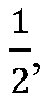
- According to some embodiments of the present invention, one or more of the STORM signal generation processes 300A, 300B, 300C, 300D, 400, 500 and/or 800 may be extended to support a multiple PA HF transmitter such as the
transmitter 102 comprising a plurality of PAs such as thePA 114, for example, 4 or 8 or 16PAs 114. In particular, while each of thePAs 114 may be of limited power, the plurality ofPAs 114 may be used to simultaneously transmit a respective one of a plurality of partial STORM signals that constitute together the overall STORM signal such that the power of the overall STORM signal is divided among the plurality ofPAs 114, each one operating with a relatively small OBO, taking advantage of the respective law-PAPR partial STORM waveform fed into it. - In some embodiments of the
multiple PA 114transmitter 102, the plurality of partial STORM signals may be spatially multiplexed and transmitted by, for example, a HF Multiple Input Multiple Output (MIMO)transmitter 102 comprising the plurality ofPAs 114, each providing a separate HF transmission path and each fed with one of the plurality of low-PAPR partial STORM signals. This implementation may be of particularly use in case Analog and/or Digital Beam-Forming (BF), so called Hybrid BF (HBF), is deployed by both thetransmitter 102 and a receiver such as thereceiver 104 in a system such as thesystem 100, and where the HF MIMO channel essentially degenerates into a set of nearly disjoint Single Input Multiple Output (SIMO) channels with low delay spreads. - In other embodiments of the
multiple PA 114transmitter 102, the plurality of partial STORM signals may be multiplexed using frequency multiplexing, optionally with some band-width overlap between successive pairs of the plurality of partial STORM signals, where each of the plurality of partial STORM signals is transmitted from a disjoint subset ofPAs 114, so as to increase the overall number of SC-FDM subcarriers exploited for the transmission, yet eachPA 114 operating with a relatively small OBO by virtue of the law-PAPR partial STORM waveform fed into it. - The descriptions of the various embodiments of the present invention have been presented for purposes of illustration, but are not intended to be exhaustive or limited to the embodiments disclosed. Many modifications and variations will be apparent to those of ordinary skill in the art without departing from the scope of the described embodiments. The terminology used herein was chosen to best explain the principles of the embodiments, the practical application or technical improvement over technologies found in the marketplace, or to enable others of ordinary skill in the art to understand the embodiments disclosed herein.
- It is expected that during the life of a patent maturing from this application many relevant FDM and/or SC transmission technologies will be developed and the scope of the terms FDM and/or SC transmission technologies respectively are intended to include all such new technologies a priori.
- As used herein the term "about" refers to ± 10 %.
- The terms "comprises", "comprising", "includes", "including", "having" and their conjugates mean "including but not limited to". This term encompasses the terms "consisting of' and "consisting essentially of".
- The phrase "consisting essentially of' means that the composition or method may include additional ingredients and/or steps, but only if the additional ingredients and/or steps do not materially alter the basic and novel characteristics of the claimed composition or method.
- As used herein, the singular form "a", "an" and "the" include plural references unless the context clearly dictates otherwise. For example, the term "a compound" or "at least one compound" may include a plurality of compounds, including mixtures thereof.
- The word "exemplary" is used herein to mean "serving as an example, instance or illustration". Any embodiment described as "exemplary" is not necessarily to be construed as preferred or advantageous over other embodiments and/or to exclude the incorporation of features from other embodiments.
- The word "optionally" is used herein to mean "is provided in some embodiments and not provided in other embodiments". Any particular embodiment of the invention may include a plurality of "optional" features unless such features conflict.
- Throughout this application, various embodiments of this invention may be presented in a range format. It should be understood that the description in range format is merely for convenience and brevity and should not be construed as an inflexible limitation on the scope of the invention. Accordingly, the description of a range should be considered to have specifically disclosed all the possible subranges as well as individual numerical values within that range. For example, description of a range such as from 1 to 6 should be considered to have specifically disclosed subranges such as from 1 to 3, from 1 to 4, from 1 to 5, from 2 to 4, from 2 to 6, from 3 to 6 etc., as well as individual numbers within that range, for example, 1, 2, 3, 4, 5, and 6. This applies regardless of the breadth of the range.
- Whenever a numerical range is indicated herein, it is meant to include any cited numeral (fractional or integral) within the indicated range. The phrases "ranging/ranges between" a first indicate number and a second indicate number and "ranging/ranges from" a first indicate number "to" a second indicate number are used herein interchangeably and are meant to include the first and second indicated numbers and all the fractional and integral numerals there between.
- It is appreciated that certain features of the invention, which are, for clarity, described in the context of separate embodiments, may also be provided in combination in a single embodiment. Conversely, various features of the invention, which are, for brevity, described in the context of a single embodiment, may also be provided separately or in any suitable subcombination or as suitable in any other described embodiment of the invention. Certain features described in the context of various embodiments are not to be considered essential features of those embodiments, unless the embodiment is inoperative without those elements.
Claims (19)
- A transmitter (102), comprising:a processor (110) adapted to:convert a primary sequence of modulation symbols (250A) into a primary signal (410A), using a primary pulse shape;convert an auxiliary sequence of modulation symbols (250B), created from the primary sequence, to an auxiliary signal (410B) using an auxiliary pulse shape; andcreate a joint output signal based on the primary signal and on the auxiliary signal,wherein the processor (110) is configured to create the auxiliary sequence (250B) from the primary sequence (250A) by generating each modulation symbol of the auxiliary sequence from a corresponding modulation symbol of the primary sequence and at least two preceding modulation symbols of the primary sequence.
- The transmitter of claim 1, wherein the processor (110) is configured to perform at least one of the following operations to the primary sequence (250A), or to the auxiliary sequence (250B), or to a compounded sequence thereof:when the processing is in frequency domain:- a complex phase shift by π/2 or a multiple thereof;- a discrete Fourier transformation, DFT;- a cyclic extension;- a filter process with information about the primary pulse shape for the primary sequence and/or about the auxiliary pulse shape for the auxiliary sequence; andwhen the processing is in time domain:- an up-sampling;- a filter process with information about the primary pulse shape for the primary sequence and/or about the auxiliary pulse shape for the auxiliary sequence.
- The transmitter of claim 1, the processor (110) being further configured to cyclically extend a plurality of finite sub-sequences of consecutive symbols of the primary sequence (250A) to create a plurality of respective finite sub-sequences of consecutive symbols of the auxiliary sequence.
- The transmitter of any of the previous claims, wherein the processor (110) is adapted for transmission of the output signal using any one of a group:- frequency division multiplexing, FDM;- discrete-Fourier-transform spread orthogonal FDM, DFT-s-OFDM;- single carrier FDM, SC-FDM;and/or a transmission based on frequency division multiple access (FDMA).
- The transmitter of any of the previous claims, wherein the processor (110) is adapted to periodically insert at least one fixed finite sequence of symbols, including a unique word, UW, into the primary sequence (250A).
- The transmitter of any of the previous claims, wherein the processor (110) is adapted to convert the primary sequence (250A) and the auxiliary sequence (250B) to frequency domain signals to create the output signal, wherein the resulting frequency domain output signal is converted back to time domain prior to transmission.
- The transmitter of claim 6, wherein the processor (110) is adapted to periodically insert guard intervals, GIs, into the time domain output signal, the guard intervals include at least one member of:- a cyclic prefix, CP;- a cyclic postfix;- a zero prefix, ZP;- and a zero tail, ZT.
- The transmitter of any of the previous claims, configured such that the primary sequence modulation symbols map a data stream to be transmitted according to a Binary-Phase Shift Keying, BPSK, modulation scheme.
- The transmitter of any of the previous claims, wherein a Peak to Average Power Ratio, PAPR, of the output signal is lower than the PAPR of the primary signal.
- The transmitter of any of the previous claims, wherein a power of the auxiliary pulse shape used for converting the auxiliary signal is smaller than a power of the primary pulse shape used for converting the primary signal by at least 10dB such that the power of the auxiliary signal is negligible with respect to the power of the primary signal.
- The transmitter of any of the previous claims, wherein the primary pulse shape and auxiliary pulse shape comply with at least one of a plurality of pulse duration constraints.
- The transmitter of any of the previous claims, wherein the processor (110) is adapted to create the output signal to comply with at least one of a plurality of signal spectral constraints.
- The transmitter of any of the previous claims, wherein the primary pulse shape and the auxiliary pulse shape are constructed using an ancestor function.
- The transmitter of any of the previous claims, wherein the auxiliary pulse shape is based on the primary pulse shape.
- The transmitter of any of claim 6 wherein the processor (110) is adapted to perform superposition in the frequency domain after separately converting the primary signal and the auxiliary signal into the frequency domain, and wherein the processor (110) is adapted to join the primary signal and the auxiliary signal through a first partial join in the time domain of the respective primary and auxiliary sequences and a second partial join in the frequency domain.
- The transmitter of any of the previous claims, configured such that the output signal is transmitted simultaneously as a plurality of partial output signals through a plurality of power amplifiers to support a multi input multi output, MIMO, transmission.
- The transmitter of any of the previous claims, configured such that the output signal is transmitted simultaneously as a plurality of partial output signals through a plurality of power amplifiers divided to a plurality of subsets.
- The transmitter of any of the previous claims, wherein the processor (110) is adapted to create at least one demodulation reference signal similarly to the output signal.
- A computer program which, when executed by a processor (110) of a transmitter (102), causes the processor to:convert a primary sequence of modulation symbols (250A) into a primary signal (410A), using a primary pulse shape;convert an auxiliary sequence of modulation symbols (250B), created from the primary sequence, to an auxiliary signal (410B) using an auxiliary pulse shape; andcreate a joint output signal based on the primary signal and on the auxiliary signal,wherein the auxiliary sequence is created from the primary sequence by generating each modulation symbol of the auxiliary sequence from a corresponding modulation symbol of the primary sequence and at least two preceding modulation symbols of the primary sequence.
Applications Claiming Priority (1)
| Application Number | Priority Date | Filing Date | Title |
|---|---|---|---|
| PCT/EP2016/077147 WO2018086684A1 (en) | 2016-11-09 | 2016-11-09 | Synthesis of near-constant modulus waveform for high frequency transmission |
Publications (2)
| Publication Number | Publication Date |
|---|---|
| EP3529957A1 EP3529957A1 (en) | 2019-08-28 |
| EP3529957B1 true EP3529957B1 (en) | 2021-09-08 |
Family
ID=57249826
Family Applications (1)
| Application Number | Title | Priority Date | Filing Date |
|---|---|---|---|
| EP16791638.6A Active EP3529957B1 (en) | 2016-11-09 | 2016-11-09 | Synthesis of near-constant modulus waveform for high frequency transmission |
Country Status (5)
| Country | Link |
|---|---|
| US (1) | US10680870B2 (en) |
| EP (1) | EP3529957B1 (en) |
| JP (1) | JP2019536391A (en) |
| CN (1) | CN109952748B (en) |
| WO (1) | WO2018086684A1 (en) |
Cited By (1)
| Publication number | Priority date | Publication date | Assignee | Title |
|---|---|---|---|---|
| US20240080233A1 (en) * | 2022-09-01 | 2024-03-07 | Qualcomm Incorporated | Techniques for waveform compression |
Families Citing this family (21)
| Publication number | Priority date | Publication date | Assignee | Title |
|---|---|---|---|---|
| US10855503B2 (en) * | 2017-01-20 | 2020-12-01 | Wisig Networks Private Limited | System and method for generating spreaded sequence with low peak-to-average power ratio (PAPR) waveform |
| EP3639490A1 (en) | 2017-08-29 | 2020-04-22 | Huawei Technologies Co., Ltd. | Efficient design and implementation of synthesis of near-constant modulus (storm) waveform |
| US10652062B2 (en) * | 2018-09-20 | 2020-05-12 | Nokia Technologies Oy | Configurable waveform for beyond 52.6GHz |
| CN111200571B (en) * | 2018-11-19 | 2021-10-01 | 华为技术有限公司 | A kind of signal transmission method and device |
| US11483870B2 (en) * | 2019-03-28 | 2022-10-25 | Qualcomm Incorporated | Resource mapping and waveform generation for uplink transmission |
| FR3102265B1 (en) * | 2019-10-16 | 2023-06-30 | Thales Sa | Zero-latency filtering method and related devices |
| WO2021112726A1 (en) | 2019-12-02 | 2021-06-10 | Telefonaktiebolaget Lm Ericsson (Publ) | Pulse-shaping optimization for high frequency radio networks |
| US11115248B2 (en) * | 2019-12-02 | 2021-09-07 | Telefonaktiebolaget Lm Ericsson (Publ) | Pulse-shaping for high frequency radio networks |
| US11063711B2 (en) * | 2019-12-03 | 2021-07-13 | Telefonaktiebolaget Lm Ericsson (Publ) | EVM for pulse-shaped signaling for high frequency radio networks |
| US11177995B2 (en) * | 2020-02-05 | 2021-11-16 | Huawei Technologies Co., Ltd. | Methods and apparatus for communicating a single carrier waveform |
| WO2021216760A1 (en) * | 2020-04-23 | 2021-10-28 | Spectral DSP Corp | Systems and methods for shaped single carrier orthogonal frequency division multiplexing with low peak to average power ratio |
| US20230049687A1 (en) * | 2020-04-23 | 2023-02-16 | Spectral DSP Corp | Systems and Methods for Shaped Single Carrier Orthogonal Frequency Division Multiplexing with Low Peak to Average Power Ratio |
| CN111817997A (en) * | 2020-07-21 | 2020-10-23 | 西安电子科技大学 | Joint Rotational Precoding and PTS Peak-to-Average Ratio Suppression Method in OFDM System |
| CN116438766A (en) * | 2020-10-15 | 2023-07-14 | 华为技术有限公司 | A method and device for transmitting signals |
| US12218785B2 (en) * | 2020-10-26 | 2025-02-04 | Samsung Electronics Co., Ltd. | Transmitter using symbol constellation rotation and spectrum shaping, transmission method thereof, receiver and reception method thereof in communication system |
| CN112383494B (en) * | 2020-11-26 | 2022-10-28 | 西安烽火电子科技有限责任公司 | Burst communication receiving system based on DSSS-OQPSK |
| CN112804180A (en) * | 2021-01-07 | 2021-05-14 | 电子科技大学 | Amplitude limiting OQAM/FBMC system signal transceiving method based on compressed sensing |
| US12348349B2 (en) * | 2021-05-13 | 2025-07-01 | Samsung Electronics Co., Ltd. | Spectrum shaping method for generating signal having almost constant envelope in communication system, and transmitter performing same |
| EP4348840A1 (en) * | 2021-05-31 | 2024-04-10 | Nokia Solutions and Networks Oy | Radio transmitter |
| CN113691265B (en) * | 2021-08-30 | 2022-05-31 | 海华电子企业(中国)有限公司 | Solid-state transmitter monitoring control protection circuit and control method thereof |
| WO2024092376A1 (en) * | 2022-10-31 | 2024-05-10 | Huawei Technologies Co., Ltd. | Systems and methods for fast beam acquisition |
Family Cites Families (18)
| Publication number | Priority date | Publication date | Assignee | Title |
|---|---|---|---|---|
| US20070211829A1 (en) * | 2001-10-22 | 2007-09-13 | Matsushita Electric Industrial Co., Ltd. | Method and apparatus for pulse optimization for non-linear filtering |
| WO2003053021A1 (en) * | 2001-12-18 | 2003-06-26 | Nokia Corporation | Method and system for generating higher order modulations with qpsk modulator |
| US7065150B2 (en) * | 2003-06-16 | 2006-06-20 | Motorola, Inc. | System and method for generating a root raised cosine orthogonal frequency division multiplexing (RRC OFDM) modulation |
| KR101009778B1 (en) * | 2003-10-23 | 2011-01-19 | 삼성전자주식회사 | Power amplification device and method having high peak power to average power ratio |
| JP4823013B2 (en) * | 2006-10-18 | 2011-11-24 | 株式会社日立製作所 | Peak factor reduction device and baseband signal processing device |
| US7859987B2 (en) * | 2005-12-20 | 2010-12-28 | Samsung Electronic Co., Ltd. | Interleaver for IEEE 802.11n standard |
| KR101100209B1 (en) * | 2005-12-27 | 2011-12-28 | 엘지전자 주식회사 | Apparatus and method for transmitting data using multiple carriers |
| JP4646845B2 (en) * | 2006-03-30 | 2011-03-09 | 富士通株式会社 | Transmitter |
| JP2007329588A (en) * | 2006-06-06 | 2007-12-20 | Fujitsu Ltd | Transmitter and transmission method |
| EP2179524B1 (en) * | 2007-08-14 | 2018-04-04 | LG Electronics Inc. | Peak to average power ratio reduction |
| US8295335B2 (en) * | 2009-12-31 | 2012-10-23 | Intel Corporation | Techniques to control uplink power |
| US9144012B2 (en) * | 2010-09-23 | 2015-09-22 | Samsung Electronics Co., Ltd. | Method and system of MIMO and beamforming transmitter and receiver architecture |
| KR101754100B1 (en) * | 2010-10-05 | 2017-07-06 | 한국전자통신연구원 | Method of multiple input multiple output transmission in digital video broadcasting system and apparatus for the same |
| US8731027B2 (en) * | 2011-12-05 | 2014-05-20 | Battelle Energy Alliance, Llc | Methods and apparatuses using filter banks for multi-carrier spread-spectrum signals |
| US8767876B2 (en) * | 2011-12-31 | 2014-07-01 | St-Ericsson Sa | Filter offset compensation |
| CN105307260A (en) * | 2014-07-24 | 2016-02-03 | 普天信息技术有限公司 | Method for sending synchronous signal sequence |
| US10686914B2 (en) * | 2014-11-04 | 2020-06-16 | Texas Instruments Incorporated | Automatic selection of MAC protocol to support multiple prime PLC standards |
| EP3384648A1 (en) * | 2015-12-03 | 2018-10-10 | IDAC Holdings, Inc. | Zero tail and unique word based waveforms for dft-s ofdm and ofdm |
-
2016
- 2016-11-09 EP EP16791638.6A patent/EP3529957B1/en active Active
- 2016-11-09 JP JP2019544770A patent/JP2019536391A/en not_active Ceased
- 2016-11-09 CN CN201680090715.8A patent/CN109952748B/en active Active
- 2016-11-09 WO PCT/EP2016/077147 patent/WO2018086684A1/en not_active Ceased
-
2019
- 2019-05-09 US US16/408,067 patent/US10680870B2/en active Active
Cited By (2)
| Publication number | Priority date | Publication date | Assignee | Title |
|---|---|---|---|---|
| US20240080233A1 (en) * | 2022-09-01 | 2024-03-07 | Qualcomm Incorporated | Techniques for waveform compression |
| US12401557B2 (en) * | 2022-09-01 | 2025-08-26 | Qualcomm Incorporated | Techniques for waveform compression |
Also Published As
| Publication number | Publication date |
|---|---|
| EP3529957A1 (en) | 2019-08-28 |
| CN109952748B (en) | 2020-11-10 |
| CN109952748A (en) | 2019-06-28 |
| WO2018086684A1 (en) | 2018-05-17 |
| US20190268202A1 (en) | 2019-08-29 |
| US10680870B2 (en) | 2020-06-09 |
| JP2019536391A (en) | 2019-12-12 |
Similar Documents
| Publication | Publication Date | Title |
|---|---|---|
| US10680870B2 (en) | Synthesis of near-constant modulus waveform for high frequency transmission | |
| US11108609B2 (en) | Efficient design and implementation of synthesis of near-constant modulus (STORM) waveform | |
| US10938876B2 (en) | Method and system for low data rate transmission | |
| JP5632457B2 (en) | Reducing peak-to-average power ratio in multicarrier signals | |
| US20150304153A1 (en) | Wireless communications device providing peak-to-average power ratio (papr) reduction based upon walsh transformation matrix permutations and related methods | |
| WO2016023495A1 (en) | System and method for generating waveforms and utilization thereof | |
| TW201012145A (en) | Peak-to-average power ratio (PAPR) reduction scheme for wireless communication | |
| US20140016721A1 (en) | Method and system for multiple training sequences for peak-to-average power ratio reduction in precoded bursts | |
| CN1956433A (en) | Multi-carrier communication system | |
| CN102160349A (en) | Technique for transmitting on multiple frequency resources in telecommunication system | |
| JP2012531127A (en) | Method and apparatus for processing component carriers aggregated for transmission | |
| CN102130875A (en) | Generation method of downlink reference signal in carrier aggregation technology | |
| Lin et al. | Modified selective mapping technique for PAPR reduction in OFDM systems | |
| CN107483379B (en) | Optimized calibration device and method for TDD-OFDM system | |
| CN111901278A (en) | Data modulation method, equipment and storage medium | |
| EP3241322B1 (en) | Method for symbol compensation and receiver | |
| Ismail et al. | Performance evaluation of PAPR in OFDM for UMTS-LTE system | |
| Eras et al. | Analysis of the PAPR Behavior of the OFDM Passband Signal | |
| Al-Rayif et al. | Experimental demonstration for PAPR reduction in OFDM system using partial-OSLM technique | |
| Mostafa et al. | Software implementation of LTE-advanced using matlab Simulink | |
| EP4300904A2 (en) | Multi-layer papr reduction | |
| EP3089416A1 (en) | Wireless communications device providing peak-to-average power ratio (papr) reduction based upon walsh transformation matrix permutations and related methods | |
| Hassanet et al. | Physical Layer Famous Waveform Approaches for Fifth Generation Cellular Network | |
| Alausta et al. | BER Performance of OFDM-QAM over AWGN and RICAIN Channels Using Error Correcting Codes | |
| Rashwan et al. | PAPR reduction in OFMD WiMAX application |
Legal Events
| Date | Code | Title | Description |
|---|---|---|---|
| STAA | Information on the status of an ep patent application or granted ep patent |
Free format text: STATUS: UNKNOWN |
|
| STAA | Information on the status of an ep patent application or granted ep patent |
Free format text: STATUS: THE INTERNATIONAL PUBLICATION HAS BEEN MADE |
|
| PUAI | Public reference made under article 153(3) epc to a published international application that has entered the european phase |
Free format text: ORIGINAL CODE: 0009012 |
|
| STAA | Information on the status of an ep patent application or granted ep patent |
Free format text: STATUS: REQUEST FOR EXAMINATION WAS MADE |
|
| 17P | Request for examination filed |
Effective date: 20190521 |
|
| AK | Designated contracting states |
Kind code of ref document: A1 Designated state(s): AL AT BE BG CH CY CZ DE DK EE ES FI FR GB GR HR HU IE IS IT LI LT LU LV MC MK MT NL NO PL PT RO RS SE SI SK SM TR |
|
| AX | Request for extension of the european patent |
Extension state: BA ME |
|
| DAV | Request for validation of the european patent (deleted) | ||
| DAX | Request for extension of the european patent (deleted) | ||
| STAA | Information on the status of an ep patent application or granted ep patent |
Free format text: STATUS: EXAMINATION IS IN PROGRESS |
|
| 17Q | First examination report despatched |
Effective date: 20200604 |
|
| GRAP | Despatch of communication of intention to grant a patent |
Free format text: ORIGINAL CODE: EPIDOSNIGR1 |
|
| STAA | Information on the status of an ep patent application or granted ep patent |
Free format text: STATUS: GRANT OF PATENT IS INTENDED |
|
| INTG | Intention to grant announced |
Effective date: 20210323 |
|
| GRAS | Grant fee paid |
Free format text: ORIGINAL CODE: EPIDOSNIGR3 |
|
| GRAA | (expected) grant |
Free format text: ORIGINAL CODE: 0009210 |
|
| STAA | Information on the status of an ep patent application or granted ep patent |
Free format text: STATUS: THE PATENT HAS BEEN GRANTED |
|
| AK | Designated contracting states |
Kind code of ref document: B1 Designated state(s): AL AT BE BG CH CY CZ DE DK EE ES FI FR GB GR HR HU IE IS IT LI LT LU LV MC MK MT NL NO PL PT RO RS SE SI SK SM TR |
|
| REG | Reference to a national code |
Ref country code: GB Ref legal event code: FG4D |
|
| REG | Reference to a national code |
Ref country code: CH Ref legal event code: EP Ref country code: AT Ref legal event code: REF Ref document number: 1429579 Country of ref document: AT Kind code of ref document: T Effective date: 20210915 |
|
| REG | Reference to a national code |
Ref country code: DE Ref legal event code: R096 Ref document number: 602016063487 Country of ref document: DE |
|
| REG | Reference to a national code |
Ref country code: IE Ref legal event code: FG4D |
|
| REG | Reference to a national code |
Ref country code: LT Ref legal event code: MG9D |
|
| REG | Reference to a national code |
Ref country code: NL Ref legal event code: MP Effective date: 20210908 |
|
| PG25 | Lapsed in a contracting state [announced via postgrant information from national office to epo] |
Ref country code: HR Free format text: LAPSE BECAUSE OF FAILURE TO SUBMIT A TRANSLATION OF THE DESCRIPTION OR TO PAY THE FEE WITHIN THE PRESCRIBED TIME-LIMIT Effective date: 20210908 Ref country code: ES Free format text: LAPSE BECAUSE OF FAILURE TO SUBMIT A TRANSLATION OF THE DESCRIPTION OR TO PAY THE FEE WITHIN THE PRESCRIBED TIME-LIMIT Effective date: 20210908 Ref country code: FI Free format text: LAPSE BECAUSE OF FAILURE TO SUBMIT A TRANSLATION OF THE DESCRIPTION OR TO PAY THE FEE WITHIN THE PRESCRIBED TIME-LIMIT Effective date: 20210908 Ref country code: NO Free format text: LAPSE BECAUSE OF FAILURE TO SUBMIT A TRANSLATION OF THE DESCRIPTION OR TO PAY THE FEE WITHIN THE PRESCRIBED TIME-LIMIT Effective date: 20211208 Ref country code: LT Free format text: LAPSE BECAUSE OF FAILURE TO SUBMIT A TRANSLATION OF THE DESCRIPTION OR TO PAY THE FEE WITHIN THE PRESCRIBED TIME-LIMIT Effective date: 20210908 Ref country code: BG Free format text: LAPSE BECAUSE OF FAILURE TO SUBMIT A TRANSLATION OF THE DESCRIPTION OR TO PAY THE FEE WITHIN THE PRESCRIBED TIME-LIMIT Effective date: 20211208 Ref country code: RS Free format text: LAPSE BECAUSE OF FAILURE TO SUBMIT A TRANSLATION OF THE DESCRIPTION OR TO PAY THE FEE WITHIN THE PRESCRIBED TIME-LIMIT Effective date: 20210908 Ref country code: SE Free format text: LAPSE BECAUSE OF FAILURE TO SUBMIT A TRANSLATION OF THE DESCRIPTION OR TO PAY THE FEE WITHIN THE PRESCRIBED TIME-LIMIT Effective date: 20210908 |
|
| REG | Reference to a national code |
Ref country code: AT Ref legal event code: MK05 Ref document number: 1429579 Country of ref document: AT Kind code of ref document: T Effective date: 20210908 |
|
| PG25 | Lapsed in a contracting state [announced via postgrant information from national office to epo] |
Ref country code: LV Free format text: LAPSE BECAUSE OF FAILURE TO SUBMIT A TRANSLATION OF THE DESCRIPTION OR TO PAY THE FEE WITHIN THE PRESCRIBED TIME-LIMIT Effective date: 20210908 Ref country code: GR Free format text: LAPSE BECAUSE OF FAILURE TO SUBMIT A TRANSLATION OF THE DESCRIPTION OR TO PAY THE FEE WITHIN THE PRESCRIBED TIME-LIMIT Effective date: 20211209 |
|
| PG25 | Lapsed in a contracting state [announced via postgrant information from national office to epo] |
Ref country code: AT Free format text: LAPSE BECAUSE OF FAILURE TO SUBMIT A TRANSLATION OF THE DESCRIPTION OR TO PAY THE FEE WITHIN THE PRESCRIBED TIME-LIMIT Effective date: 20210908 |
|
| PG25 | Lapsed in a contracting state [announced via postgrant information from national office to epo] |
Ref country code: IS Free format text: LAPSE BECAUSE OF FAILURE TO SUBMIT A TRANSLATION OF THE DESCRIPTION OR TO PAY THE FEE WITHIN THE PRESCRIBED TIME-LIMIT Effective date: 20220108 Ref country code: SM Free format text: LAPSE BECAUSE OF FAILURE TO SUBMIT A TRANSLATION OF THE DESCRIPTION OR TO PAY THE FEE WITHIN THE PRESCRIBED TIME-LIMIT Effective date: 20210908 Ref country code: SK Free format text: LAPSE BECAUSE OF FAILURE TO SUBMIT A TRANSLATION OF THE DESCRIPTION OR TO PAY THE FEE WITHIN THE PRESCRIBED TIME-LIMIT Effective date: 20210908 Ref country code: RO Free format text: LAPSE BECAUSE OF FAILURE TO SUBMIT A TRANSLATION OF THE DESCRIPTION OR TO PAY THE FEE WITHIN THE PRESCRIBED TIME-LIMIT Effective date: 20210908 Ref country code: PT Free format text: LAPSE BECAUSE OF FAILURE TO SUBMIT A TRANSLATION OF THE DESCRIPTION OR TO PAY THE FEE WITHIN THE PRESCRIBED TIME-LIMIT Effective date: 20220110 Ref country code: PL Free format text: LAPSE BECAUSE OF FAILURE TO SUBMIT A TRANSLATION OF THE DESCRIPTION OR TO PAY THE FEE WITHIN THE PRESCRIBED TIME-LIMIT Effective date: 20210908 Ref country code: NL Free format text: LAPSE BECAUSE OF FAILURE TO SUBMIT A TRANSLATION OF THE DESCRIPTION OR TO PAY THE FEE WITHIN THE PRESCRIBED TIME-LIMIT Effective date: 20210908 Ref country code: EE Free format text: LAPSE BECAUSE OF FAILURE TO SUBMIT A TRANSLATION OF THE DESCRIPTION OR TO PAY THE FEE WITHIN THE PRESCRIBED TIME-LIMIT Effective date: 20210908 Ref country code: CZ Free format text: LAPSE BECAUSE OF FAILURE TO SUBMIT A TRANSLATION OF THE DESCRIPTION OR TO PAY THE FEE WITHIN THE PRESCRIBED TIME-LIMIT Effective date: 20210908 Ref country code: AL Free format text: LAPSE BECAUSE OF FAILURE TO SUBMIT A TRANSLATION OF THE DESCRIPTION OR TO PAY THE FEE WITHIN THE PRESCRIBED TIME-LIMIT Effective date: 20210908 |
|
| REG | Reference to a national code |
Ref country code: DE Ref legal event code: R097 Ref document number: 602016063487 Country of ref document: DE |
|
| PG25 | Lapsed in a contracting state [announced via postgrant information from national office to epo] |
Ref country code: MC Free format text: LAPSE BECAUSE OF FAILURE TO SUBMIT A TRANSLATION OF THE DESCRIPTION OR TO PAY THE FEE WITHIN THE PRESCRIBED TIME-LIMIT Effective date: 20210908 |
|
| REG | Reference to a national code |
Ref country code: CH Ref legal event code: PL |
|
| PLBE | No opposition filed within time limit |
Free format text: ORIGINAL CODE: 0009261 |
|
| STAA | Information on the status of an ep patent application or granted ep patent |
Free format text: STATUS: NO OPPOSITION FILED WITHIN TIME LIMIT |
|
| PG25 | Lapsed in a contracting state [announced via postgrant information from national office to epo] |
Ref country code: LU Free format text: LAPSE BECAUSE OF NON-PAYMENT OF DUE FEES Effective date: 20211109 Ref country code: DK Free format text: LAPSE BECAUSE OF FAILURE TO SUBMIT A TRANSLATION OF THE DESCRIPTION OR TO PAY THE FEE WITHIN THE PRESCRIBED TIME-LIMIT Effective date: 20210908 Ref country code: BE Free format text: LAPSE BECAUSE OF NON-PAYMENT OF DUE FEES Effective date: 20211130 |
|
| REG | Reference to a national code |
Ref country code: BE Ref legal event code: MM Effective date: 20211130 |
|
| 26N | No opposition filed |
Effective date: 20220609 |
|
| GBPC | Gb: european patent ceased through non-payment of renewal fee |
Effective date: 20211208 |
|
| PG25 | Lapsed in a contracting state [announced via postgrant information from national office to epo] |
Ref country code: SI Free format text: LAPSE BECAUSE OF FAILURE TO SUBMIT A TRANSLATION OF THE DESCRIPTION OR TO PAY THE FEE WITHIN THE PRESCRIBED TIME-LIMIT Effective date: 20210908 |
|
| PG25 | Lapsed in a contracting state [announced via postgrant information from national office to epo] |
Ref country code: IE Free format text: LAPSE BECAUSE OF NON-PAYMENT OF DUE FEES Effective date: 20211109 Ref country code: GB Free format text: LAPSE BECAUSE OF NON-PAYMENT OF DUE FEES Effective date: 20211208 |
|
| PG25 | Lapsed in a contracting state [announced via postgrant information from national office to epo] |
Ref country code: FR Free format text: LAPSE BECAUSE OF NON-PAYMENT OF DUE FEES Effective date: 20211130 |
|
| PG25 | Lapsed in a contracting state [announced via postgrant information from national office to epo] |
Ref country code: IT Free format text: LAPSE BECAUSE OF FAILURE TO SUBMIT A TRANSLATION OF THE DESCRIPTION OR TO PAY THE FEE WITHIN THE PRESCRIBED TIME-LIMIT Effective date: 20210908 |
|
| PG25 | Lapsed in a contracting state [announced via postgrant information from national office to epo] |
Ref country code: CY Free format text: LAPSE BECAUSE OF FAILURE TO SUBMIT A TRANSLATION OF THE DESCRIPTION OR TO PAY THE FEE WITHIN THE PRESCRIBED TIME-LIMIT Effective date: 20210908 |
|
| PG25 | Lapsed in a contracting state [announced via postgrant information from national office to epo] |
Ref country code: LI Free format text: LAPSE BECAUSE OF NON-PAYMENT OF DUE FEES Effective date: 20220630 Ref country code: HU Free format text: LAPSE BECAUSE OF FAILURE TO SUBMIT A TRANSLATION OF THE DESCRIPTION OR TO PAY THE FEE WITHIN THE PRESCRIBED TIME-LIMIT; INVALID AB INITIO Effective date: 20161109 Ref country code: CH Free format text: LAPSE BECAUSE OF NON-PAYMENT OF DUE FEES Effective date: 20220630 |
|
| PG25 | Lapsed in a contracting state [announced via postgrant information from national office to epo] |
Ref country code: MK Free format text: LAPSE BECAUSE OF FAILURE TO SUBMIT A TRANSLATION OF THE DESCRIPTION OR TO PAY THE FEE WITHIN THE PRESCRIBED TIME-LIMIT Effective date: 20210908 |
|
| PG25 | Lapsed in a contracting state [announced via postgrant information from national office to epo] |
Ref country code: TR Free format text: LAPSE BECAUSE OF FAILURE TO SUBMIT A TRANSLATION OF THE DESCRIPTION OR TO PAY THE FEE WITHIN THE PRESCRIBED TIME-LIMIT Effective date: 20210908 |
|
| PG25 | Lapsed in a contracting state [announced via postgrant information from national office to epo] |
Ref country code: MT Free format text: LAPSE BECAUSE OF FAILURE TO SUBMIT A TRANSLATION OF THE DESCRIPTION OR TO PAY THE FEE WITHIN THE PRESCRIBED TIME-LIMIT Effective date: 20210908 |
|
| PGFP | Annual fee paid to national office [announced via postgrant information from national office to epo] |
Ref country code: DE Payment date: 20250930 Year of fee payment: 10 |