EP3529522B1 - Lattice control cage for a regulator - Google Patents
Lattice control cage for a regulator Download PDFInfo
- Publication number
- EP3529522B1 EP3529522B1 EP17795104.3A EP17795104A EP3529522B1 EP 3529522 B1 EP3529522 B1 EP 3529522B1 EP 17795104 A EP17795104 A EP 17795104A EP 3529522 B1 EP3529522 B1 EP 3529522B1
- Authority
- EP
- European Patent Office
- Prior art keywords
- cage
- lattice structure
- lattice
- fluid
- trim assembly
- Prior art date
- Legal status (The legal status is an assumption and is not a legal conclusion. Google has not performed a legal analysis and makes no representation as to the accuracy of the status listed.)
- Active
Links
Images



Classifications
-
- F—MECHANICAL ENGINEERING; LIGHTING; HEATING; WEAPONS; BLASTING
- F16—ENGINEERING ELEMENTS AND UNITS; GENERAL MEASURES FOR PRODUCING AND MAINTAINING EFFECTIVE FUNCTIONING OF MACHINES OR INSTALLATIONS; THERMAL INSULATION IN GENERAL
- F16K—VALVES; TAPS; COCKS; ACTUATING-FLOATS; DEVICES FOR VENTING OR AERATING
- F16K1/00—Lift valves or globe valves, i.e. cut-off apparatus with closure members having at least a component of their opening and closing motion perpendicular to the closing faces
- F16K1/32—Details
- F16K1/34—Cutting-off parts, e.g. valve members, seats
- F16K1/36—Valve members
-
- F—MECHANICAL ENGINEERING; LIGHTING; HEATING; WEAPONS; BLASTING
- F16—ENGINEERING ELEMENTS AND UNITS; GENERAL MEASURES FOR PRODUCING AND MAINTAINING EFFECTIVE FUNCTIONING OF MACHINES OR INSTALLATIONS; THERMAL INSULATION IN GENERAL
- F16K—VALVES; TAPS; COCKS; ACTUATING-FLOATS; DEVICES FOR VENTING OR AERATING
- F16K47/00—Means in valves for absorbing fluid energy
- F16K47/08—Means in valves for absorbing fluid energy for decreasing pressure or noise level and having a throttling member separate from the closure member, e.g. screens, slots, labyrinths
- F16K47/14—Means in valves for absorbing fluid energy for decreasing pressure or noise level and having a throttling member separate from the closure member, e.g. screens, slots, labyrinths the throttling member being a perforated membrane
-
- B—PERFORMING OPERATIONS; TRANSPORTING
- B01—PHYSICAL OR CHEMICAL PROCESSES OR APPARATUS IN GENERAL
- B01D—SEPARATION
- B01D35/00—Filtering devices having features not specifically covered by groups B01D24/00 - B01D33/00, or for applications not specifically covered by groups B01D24/00 - B01D33/00; Auxiliary devices for filtration; Filter housing constructions
- B01D35/02—Filters adapted for location in special places, e.g. pipe-lines, pumps, stop-cocks
- B01D35/04—Plug, tap, or cock filters filtering elements mounted in or on a faucet
-
- F—MECHANICAL ENGINEERING; LIGHTING; HEATING; WEAPONS; BLASTING
- F16—ENGINEERING ELEMENTS AND UNITS; GENERAL MEASURES FOR PRODUCING AND MAINTAINING EFFECTIVE FUNCTIONING OF MACHINES OR INSTALLATIONS; THERMAL INSULATION IN GENERAL
- F16K—VALVES; TAPS; COCKS; ACTUATING-FLOATS; DEVICES FOR VENTING OR AERATING
- F16K1/00—Lift valves or globe valves, i.e. cut-off apparatus with closure members having at least a component of their opening and closing motion perpendicular to the closing faces
- F16K1/32—Details
-
- F—MECHANICAL ENGINEERING; LIGHTING; HEATING; WEAPONS; BLASTING
- F16—ENGINEERING ELEMENTS AND UNITS; GENERAL MEASURES FOR PRODUCING AND MAINTAINING EFFECTIVE FUNCTIONING OF MACHINES OR INSTALLATIONS; THERMAL INSULATION IN GENERAL
- F16K—VALVES; TAPS; COCKS; ACTUATING-FLOATS; DEVICES FOR VENTING OR AERATING
- F16K3/00—Gate valves or sliding valves, i.e. cut-off apparatus with closing members having a sliding movement along the seat for opening and closing
- F16K3/22—Gate valves or sliding valves, i.e. cut-off apparatus with closing members having a sliding movement along the seat for opening and closing with sealing faces shaped as surfaces of solids of revolution
- F16K3/24—Gate valves or sliding valves, i.e. cut-off apparatus with closing members having a sliding movement along the seat for opening and closing with sealing faces shaped as surfaces of solids of revolution with cylindrical valve members
- F16K3/246—Combination of a sliding valve and a lift valve
-
- F—MECHANICAL ENGINEERING; LIGHTING; HEATING; WEAPONS; BLASTING
- F16—ENGINEERING ELEMENTS AND UNITS; GENERAL MEASURES FOR PRODUCING AND MAINTAINING EFFECTIVE FUNCTIONING OF MACHINES OR INSTALLATIONS; THERMAL INSULATION IN GENERAL
- F16K—VALVES; TAPS; COCKS; ACTUATING-FLOATS; DEVICES FOR VENTING OR AERATING
- F16K47/00—Means in valves for absorbing fluid energy
- F16K47/08—Means in valves for absorbing fluid energy for decreasing pressure or noise level and having a throttling member separate from the closure member, e.g. screens, slots, labyrinths
Definitions
- the disclosure relates generally to fluid valves and, more particularly, to trim assemblies that include a lattice control cage.
- Control valves are commonly used in process plants to control the flow of a fluid (e.g., a gas, a liquid, etc.) or any other substance through pipes and/or vessels to which they are connected.
- a control valve is typically composed of one or more inlets and outlets, and includes a fluid control element or member (e.g., a valve gate, a piston, a valve plug, a control member, etc.) that operates to control fluid flow through apertures that fluidly couple the inlet(s) to the outlet(s).
- a control member is typically coupled to a valve bonnet that is mechanically coupled (e.g., bolted, clamped, threaded into, etc.) to the valve body.
- the control member is configured to engage a sealing structure (e.g., a valve seat) that encompasses a flow path through the valve.
- a regulator is a self-controlling form of a control valve.
- valve trim or “trim assembly” in the art.
- a trim assembly may be used that includes a cage with a plurality of openings that are drilled, cast, punched, machined etc., through a wall of the cage.
- the openings may be sized and shaped to characterize fluid flow as the fluid flows through the openings in the cage, for example by decreasing pressure as the fluid moves through the valve trim. This characterization or pressure reducing process generates unwanted noise.
- the present application refers to a trim assembly for a fluid valve according to claim 1.
- the examples described herein relate to fluid control valves having a trim assembly that includes a cage having a lattice structure.
- Such cage lattice structures allow the trim assembly to control cavitation and flow characteristics (and thus noise) by wake, pressure drop, and bubble nuclei generation.
- the examples described herein substantially reduce the amount of noise generated by the trim assembly, which extends the useful life of valve components.
- the cage lattice structures may be manufactured with additive or non-standard manufacturing techniques, such as 3D printing, which allows the cages to be custom produced if needed and delivered quickly. Standard manufacturing techniques are subtractive techniques, such as drilling, machining, punching, and casting. Moreover, the cage lattice structures provide more structural support for a given open area than conventional cages. Still further, the cage lattice structures eliminate the no-flow areas needed by conventional cages that have windows.
- the cage lattice structures described below are customizable to optimize strength, opening speed, linear flow, hybrid linear quick-open flow, cavitation reduction, noise reduction, and material reduction, while at the same time the lattice density (or lattice density gradient) may be varied across the lattice structure to simulate a quick-opening, linear, or hybrid flow response.
- a regulator is a self-controlling form of a control valve and the disclosed lattice structures may be applied equally to control valves and to regulators.
- control valve and “regulator” may be used interchangeably.
- the term "lattice structure" is defined to include a plurality of diagonal (or horizontal and vertical) structural elements that form a plurality of diamond, square-shaped, round, or spherical openings in a pattern.
- the plurality of structural elements may be separate elements, or the elements may be joined together (or formed together) so make an integral structure having a lattice pattern.
- lattice density is defined to include the amount of open space in the lattice structure that is available for fluid flow for a given square millimeter.
- lattice density may include values between 0.3 mm 2 per square mm and 0.6 mm 2 per square mm.
- the lattice density above may be stated as 30% open area to 60% open area.
- the structure of the lattice would take up the remaining 0.7 mm 2 to 0.4 mm 2 , respectively.
- lattice densities between 1% and 99% are possible in the lattice structures described below.
- the term "lattice density gradient" is defined to include the rate of change in the lattice density across a certain spatial dimension.
- the lattice density may change across a thickness of the lattice structure or across a height of the lattice structure. The rate of such change is defined as the "lattice density gradient.”
- FIG. 1 illustrates an example fluid valve 100 that has a valve body 102 including a fluid flow passageway 104 between an inlet 106 and an outlet 108.
- a bonnet 110 is coupled to the valve body 102 via a plurality of fasteners 112 and includes a bore 114 to receive a stem 116.
- An end 118 of the stem 116 extends from a bonnet body 120 and is operatively coupled to an actuator (not shown), and an opposite end 122 of the stem 116 is coupled to a control member 124 (e.g., a valve plug).
- a control member 124 e.g., a valve plug
- a valve trim assembly 126 of the example fluid valve 100 includes a cage retainer 128 (e.g., an upper cage retainer or guide), a cage 130, and a seat 142.
- a cage retainer 128 e.g., an upper cage retainer or guide
- the cage retainer 128 and the cage 130 are illustrated as separate and distinct structural elements.
- the cage 130 and the cage retainer 128 may be formed as a single unitary structural element.
- an end 132 of the cage retainer 128 is positioned at least partially within the valve body 102 and adjacent the bonnet 110 and an opposing end 134 of the cage retainer 128 engages an end 136 of the cage 130 such that the cage retainer 128 and the cage 130 are coaxially aligned.
- the cage 130 is positioned within the valve body 102 such that opposing steps or shoulders 138 and 140 of the cage 130 and the seat 142 (e.g., a seat ring) engage and/or interlock to secure the seat 142 at least partially within an aperture 144 of the valve body 102.
- Such an approach eliminates the need for a plurality of fasteners to secure the seat 142 relative to the valve body 102 and, thus, the distortion caused, in some instances, when coupling a seat ring to a valve body. Additionally, by eliminating the need for a plurality of fasteners to secure the seat 142, the seat 142 may be more easily removed from and/or assembled within the example fluid valve 100 during, for example, routine maintenance.
- the cages 130 described herein may be used in valves without a cage retainer 128 and/or with an integrally formed cage retainer 128.
- the cage 130 includes a lattice structure 160 formed in a central portion of the cage 130.
- the lattice structure 160 includes a plurality of openings 162 that allow fluid to flow through the cage 130.
- the lattice structure 160 forms part of a cage wall 164. The lattice structure 160 will be described further below.
- the cage retainer 128, the seat 142, the valve body 102 and/or any other valve components may include a dynamic joint 152.
- the dynamic joint 152 may be eliminated and the cage retainer 128 may be directly coupled to the bonnet 110. Where the dynamic joint 152 is included, it allows the cage 130 and the cage retainer 128 to expand/contract (e.g., in response to thermal cycles) while enabling the cage 130 to remain in contact with the seat 142 to maintain the seat 142 in sealing engagement with the aperture 144.
- the trim assembly 126 cooperates with the control member 124 to control fluid flow through the fluid passageway 104, the trim assembly 126 includes the cage 130 and the cage retainer 128. In some embodiments, the trim assembly 126 may also include the seat 142.
- an example of lattice structure 160 includes a plurality of structural elements 166 that form a pattern of openings 162.
- the openings may be diamond-shaped or square-shaped, as illustrated. In other embodiments, the openings may have other shapes.
- the structural elements 166 are oriented at 45 degree angles relative to a longitudinal axis A of the cage in the embodiment of FIGS. 2 and 3 .
- the lattice structure 160 is located between a first or upper cage ring 170 and a second or lower cage ring 172, the lattice structure 160 forming part of the cage wall 164.
- the lattice structure 160 may be recessed radially inward from an exterior edge 174 of the first cage ring 170 and/or from an exterior edge 176 of the second cage ring 172.
- the lattice structure 160 may be joined to the first cage ring 170 and to the second cage ring 172 with a radius or fillet. The radius reduces stress between the lattice structure 160 and between the first and second cage rings 170, 172.
- a filter 180 is disposed adjacent to the lattice structure 160.
- the filter 180 is located on an upstream side of the lattice structure 160 to prevent any large particles from entering the lattice structure 160, which could damage the lattice structure 160.
- the filter 180 is located radially inward of the lattice structure.
- the filter 180 includes a plurality of openings 182. The openings in the plurality of openings 182 are smaller than the openings 162 in the lattice structure 160.
- the filter 180 is printed adjacent to the lattice structure 160 by a 3D printing technique.
- the filter 180 may be inserted into the cage 130 adjacent to the lattice structure 160.
- the filter 180 extends into first and second cage rings 170, 172. More specifically, a first end 184 of the filter 180 may be located within a channel 185 formed in the first cage ring 170 and a second end of the filter 188 may be located within a channel 190 of the second cage ring 172.
- the channels 185, 188 positively retain the filter 180 within the cage 130.
- the lattice density and/or lattice density gradient may be customized to act as both a flow characteristic control and as a filter.
- the lattice structure 160 may include the structural elements 166, which are oriented perpendicular to and parallel to the longitudinal axis A of the cage 130.
- the lattice structure has a uniform lattice density.
- the openings 162 are uniform in size and shape, and the openings 162 are uniformly spaced about the lattice structure 160.
- the lattice structure 160 may include a non-uniform lattice density. More specifically, the lattice density changes from an inner surface 191 to an outer surface 192 (i.e., along a thickness of the lattice structure 160, radially from inside the cage 130 to outside of the cage 130).
- the lattice structure 160 is most dense (i.e., has the least open area per mm 2 ) at the inner surface 191 and the lattice structure 160 is the least dense (i.e., has the most open area per mm 2 ) at the outer surface 192.
- the lattice structure 160 may have a density of about 0.3 mm open area per mm 2 at the inner surface 191 and a density of about 0.60 mm open area per mm 2 at the outer surface 192.
- the lattice structure 160 may have a density of about 30% open area at the inner surface 191 and about 60% open area at the outer surface 192.
- the lattice density changes in discrete sections. In a first section 193, the lattice density is about 30%. In a second section 195, the lattice density is about 37.5%. In a third section 197, the lattice density is about 45%. In a fourth section 198, the lattice density is about 52.5%. In a fifth section 199, the lattice density is about 60%.
- the lattice structure 160 in other examples may include any range of lattice densities between 1% and 99%. While the lattice density is illustrated in FIG. 7 as changing in discrete sections, in other examples the lattice density may change continuously and smoothly from the inner surface 191 to the outer surface 192. While the lattice density is illustrated in FIG. 7 to be the most dense near the inner surface 191 and the least dense near the outer surface 192, in other examples, the lattice density may be least dense near the inner surface 191 and most dense near the outer surface 192. In yet other examples, the lattice density may increase and decrease one or more times across a thickness of the lattice structure 160. For example, the lattice density may be most dense at a location somewhere between the inner surface 191 and the outer surface 192.
- the lattice density gradient across the lattice structure 160 may be linear or non-linear.
- the example of FIG. 7 with non-uniform lattice density, reduces cavitation more effectively than current cages because the non-uniform lattice density reduces cavitation in three different ways simultaneously.
- the non-uniform lattice density reduces cavitation by reducing pressure.
- the non-uniform lattice density reduces cavitation by controlling wake behavior.
- the non-uniform lattice density reduces cavitation by triggering nuclei formation. As a result, the lattice structure 160 is very effective in reducing cavitation.
- the lattice structure 160 may include a non-uniform lattice density, similar to the example of FIG. 7 .
- the example of FIG. 8 includes non-uniform lattice density in the axial (longitudinal) direction B.
- the lattice density changes from a bottom edge 194 to an upper edge 196 (i.e., along a height of the lattice structure 160, from bottom to top).
- the lattice structure 160 is most dense (i.e., has the least open area per mm 2 ) near the bottom edge 194 and the lattice structure 160 is the least dense (i.e., has the most open area per mm 2 ) at near the top edge 196.
- the lattice structure 160 in other examples may include any range of lattice densities between 1% and 99%. While the lattice density is illustrated in FIG. 8 as changing continuously and smoothly, in other examples, the lattice density may change in discrete sections from the bottom edge 194 to the upper edge 196. While the lattice density is illustrated in FIG. 8 to be the most dense near the bottom edge 194 and the least dense near the upper edge 196, in other examples, the lattice density may be least dense near the bottom edge 194 and most dense near the upper edge 196. In yet other examples, the lattice density may increase and decrease one or more times across a height of the lattice structure 160. For example, the lattice density may be most dense at a location somewhere between the bottom edge 194 and the upper edge 196.
- FIG. 8 is more effective at reducing cavitation than conventional cages for the same reasons as the example of FIG. 7 .
- the example of FIG. 8 produces different flow characteristics based on the location of the plug (e.g., how open or closed is the valve).
- the lattice structure 160 includes a non-uniform lattice density, similar to the examples of FIGS. 7 and 8 .
- the embodiment of FIG. 9 includes non-uniform lattice density in both the axial direction B and in the radial direction (inside out).
- the lattice density changes from the bottom edge 194 to the upper edge 196 (i.e., along a height of the lattice structure 160, from bottom to top) and also from the inner surface 191 to the outer surface 192.
- FIG. 9 includes non-uniform lattice density in both the axial direction B and in the radial direction (inside out).
- the lattice density changes from the bottom edge 194 to the upper edge 196 (i.e., along a height of the lattice structure 160, from bottom to top) and also from the inner surface 191 to the outer surface 192.
- the lattice structure 160 is most dense (i.e., has the least open area per mm 2 ) near the intersection of the bottom edge 194 and the inner surface 191 and the lattice structure 160 is the least dense (i.e., has the most open area per mm 2 ) near the intersection of the top edge 196 and the outer surface 192.
- the lattice structure 160 in other embodiments may include any range of lattice densities between 1% and 99%. While the lattice density is illustrated in FIG. 9 as changing continuously and smoothly, in other embodiments, the lattice density may change in discrete sections from the bottom edge 194 to the upper edge 196 and from the inner surface 191 to the outer surface 193. While the lattice density is illustrated in FIG. 9 to be the most dense near the bottom edge 194 and near the inner surface 191 and the least dense near the upper edge 196 and near the outer surface 192, in other embodiments, the lattice density may be least dense near the bottom edge 194 and near the inner surface 191 and most dense near the upper edge 196 and near the outer surface 192.
- the lattice density may increase and decrease one or more times across a height and radius of the lattice structure 160.
- the lattice density may be most dense at a location somewhere between the bottom edge 194 and the upper edge 196 and between the inner surface 191 and the outer surface 192.
- FIG. 9 is more effective at reducing cavitation than conventional cages for the same reasons as the examples of FIGS. 7 and 8 .
- the embodiment of FIG. 9 combines advantages of both the example of FIG. 7 and the example of FIG. 8 .
Landscapes
- Engineering & Computer Science (AREA)
- General Engineering & Computer Science (AREA)
- Mechanical Engineering (AREA)
- Water Supply & Treatment (AREA)
- Chemical & Material Sciences (AREA)
- Chemical Kinetics & Catalysis (AREA)
- Details Of Valves (AREA)
- Sliding Valves (AREA)
Description
- The disclosure relates generally to fluid valves and, more particularly, to trim assemblies that include a lattice control cage.
- Control valves are commonly used in process plants to control the flow of a fluid (e.g., a gas, a liquid, etc.) or any other substance through pipes and/or vessels to which they are connected. A control valve is typically composed of one or more inlets and outlets, and includes a fluid control element or member (e.g., a valve gate, a piston, a valve plug, a control member, etc.) that operates to control fluid flow through apertures that fluidly couple the inlet(s) to the outlet(s). A control member is typically coupled to a valve bonnet that is mechanically coupled (e.g., bolted, clamped, threaded into, etc.) to the valve body. Typically, the control member is configured to engage a sealing structure (e.g., a valve seat) that encompasses a flow path through the valve. A regulator is a self-controlling form of a control valve.
- Generally speaking the control elements (including the fluid control member, the seat, and a cage) are known as "valve trim" or "trim assembly" in the art. In some cases it may be desirable to characterize fluid as it flows through the valve, for example, to reduce pressure. In these cases, a trim assembly may be used that includes a cage with a plurality of openings that are drilled, cast, punched, machined etc., through a wall of the cage. The openings may be sized and shaped to characterize fluid flow as the fluid flows through the openings in the cage, for example by decreasing pressure as the fluid moves through the valve trim. This characterization or pressure reducing process generates unwanted noise. Currently, cavitation is controlled by using pressure drops and sound reduction is done by cages having a plurality of holes drilled, cast, punched, machined, etc., into a cage wall. A known control valve trim assembly having a cage with diamond-shaped openings is described in the document
US-A-2015/0108379 . DocumentUS-A-2003/0192601 describes a low noise fluid control valve. DocumentUS-A-3722854 describes a valve with perforated ribbon silencing element. - The present application refers to a trim assembly for a fluid valve according to claim 1.
-
-
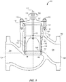
FIG. 1 illustrates a cross-sectional view of a fluid control valve constructed in accordance with the teachings of the disclosure; -
FIG. 2 illustrates a perspective view of a cage of a trim assembly, not part of the present invention. -
FIG. 3 illustrates a cross-sectional view of the cage ofFIG. 2 . -
FIG. 4 illustrates a cross-sectional view of a second example of a cage of a trim assembly, which is not part of the present invention, the cage having a printed inner filter. -
FIG. 5 illustrates a cross-sectional view of a third example of a cage of a trim assembly, which is not part of the present invention, the cage having a trapped inner filter. -
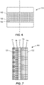
FIG. 6 illustrates a plan view of a fourth example of trim assembly, which is not part of the present invention, the lattice structure having uniform lattice density. -
FIG. 7 illustrates a plan view of a fifth example of a cage of a trim assembly, which is not part of the present invention, the lattice structure having a lattice that differs in density through a thickness of the cage. -
FIG. 8 illustrates a plan view of a sixth example of a cage of a trim assembly, which is not part of the present invention, the lattice structure having a lattice that differs in density along a height of the cage. -
FIG. 9 illustrates a plan view of the cage of the trim assembly according to the invention, the lattice structure having a lattice that differs in density through a thickness of the cage and along a height of the cage. - Certain examples are shown in the above-identified figures and described in detail below. In describing these examples, like or identical reference numbers are used to identify the same or similar elements. The figures are not necessarily to scale and certain features and certain views of the figures may be shown exaggerated in scale or in schematic for clarity and/or conciseness. Additionally, several examples have been described throughout this specification. Any features from any example may be included with, a replacement for, or otherwise combined with other features from other examples.
- The examples described herein relate to fluid control valves having a trim assembly that includes a cage having a lattice structure. Such cage lattice structures allow the trim assembly to control cavitation and flow characteristics (and thus noise) by wake, pressure drop, and bubble nuclei generation. The examples described herein substantially reduce the amount of noise generated by the trim assembly, which extends the useful life of valve components.
- Furthermore, the cage lattice structures may be manufactured with additive or non-standard manufacturing techniques, such as 3D printing, which allows the cages to be custom produced if needed and delivered quickly. Standard manufacturing techniques are subtractive techniques, such as drilling, machining, punching, and casting. Moreover, the cage lattice structures provide more structural support for a given open area than conventional cages. Still further, the cage lattice structures eliminate the no-flow areas needed by conventional cages that have windows. The cage lattice structures described below are customizable to optimize strength, opening speed, linear flow, hybrid linear quick-open flow, cavitation reduction, noise reduction, and material reduction, while at the same time the lattice density (or lattice density gradient) may be varied across the lattice structure to simulate a quick-opening, linear, or hybrid flow response.
- A regulator is a self-controlling form of a control valve and the disclosed lattice structures may be applied equally to control valves and to regulators. For the purposes of this patent, the terms "control valve" and "regulator" may be used interchangeably.
- As used herein, the term "lattice structure" is defined to include a plurality of diagonal (or horizontal and vertical) structural elements that form a plurality of diamond, square-shaped, round, or spherical openings in a pattern. The plurality of structural elements may be separate elements, or the elements may be joined together (or formed together) so make an integral structure having a lattice pattern.
- As used herein, the term "lattice density" is defined to include the amount of open space in the lattice structure that is available for fluid flow for a given square millimeter. For example, lattice density may include values between 0.3 mm2 per square mm and 0.6 mm2 per square mm. On a percentage basis, the lattice density above may be stated as 30% open area to 60% open area. In such lattice density values, the structure of the lattice would take up the remaining 0.7 mm2 to 0.4 mm2, respectively. Generally, lattice densities between 1% and 99% are possible in the lattice structures described below.
- As used herein, the term "lattice density gradient" is defined to include the rate of change in the lattice density across a certain spatial dimension. For example, the lattice density may change across a thickness of the lattice structure or across a height of the lattice structure. The rate of such change is defined as the "lattice density gradient."
-
FIG. 1 illustrates anexample fluid valve 100 that has avalve body 102 including afluid flow passageway 104 between aninlet 106 and anoutlet 108. Abonnet 110 is coupled to thevalve body 102 via a plurality offasteners 112 and includes abore 114 to receive astem 116. Anend 118 of thestem 116 extends from abonnet body 120 and is operatively coupled to an actuator (not shown), and anopposite end 122 of thestem 116 is coupled to a control member 124 (e.g., a valve plug). - As used herein, a
valve trim assembly 126 of theexample fluid valve 100 includes a cage retainer 128 (e.g., an upper cage retainer or guide), acage 130, and aseat 142. In the embodiments illustrated in the figures, thecage retainer 128 and thecage 130 are illustrated as separate and distinct structural elements. In other embodiments, thecage 130 and thecage retainer 128 may be formed as a single unitary structural element. - Generally, an
end 132 of thecage retainer 128 is positioned at least partially within thevalve body 102 and adjacent thebonnet 110 and anopposing end 134 of thecage retainer 128 engages anend 136 of thecage 130 such that thecage retainer 128 and thecage 130 are coaxially aligned. Thecage 130 is positioned within thevalve body 102 such that opposing steps orshoulders cage 130 and the seat 142 (e.g., a seat ring) engage and/or interlock to secure theseat 142 at least partially within anaperture 144 of thevalve body 102. Such an approach eliminates the need for a plurality of fasteners to secure theseat 142 relative to thevalve body 102 and, thus, the distortion caused, in some instances, when coupling a seat ring to a valve body. Additionally, by eliminating the need for a plurality of fasteners to secure theseat 142, theseat 142 may be more easily removed from and/or assembled within the examplefluid valve 100 during, for example, routine maintenance. In other embodiments, thecages 130 described herein may be used in valves without acage retainer 128 and/or with an integrally formedcage retainer 128. - The
cage 130 includes alattice structure 160 formed in a central portion of thecage 130. Thelattice structure 160 includes a plurality ofopenings 162 that allow fluid to flow through thecage 130. Thelattice structure 160 forms part of a cage wall 164. Thelattice structure 160 will be described further below. - In one example, the
cage retainer 128, theseat 142, thevalve body 102 and/or any other valve components, may include a dynamic joint 152. In other embodiments, the dynamic joint 152 may be eliminated and thecage retainer 128 may be directly coupled to thebonnet 110. Where the dynamic joint 152 is included, it allows thecage 130 and thecage retainer 128 to expand/contract (e.g., in response to thermal cycles) while enabling thecage 130 to remain in contact with theseat 142 to maintain theseat 142 in sealing engagement with theaperture 144. - The
trim assembly 126 cooperates with thecontrol member 124 to control fluid flow through thefluid passageway 104, thetrim assembly 126 includes thecage 130 and thecage retainer 128. In some embodiments, thetrim assembly 126 may also include theseat 142. - As illustrated in
FIGS. 2 and 3 , an example oflattice structure 160 includes a plurality ofstructural elements 166 that form a pattern ofopenings 162. The openings may be diamond-shaped or square-shaped, as illustrated. In other embodiments, the openings may have other shapes. Thestructural elements 166 are oriented at 45 degree angles relative to a longitudinal axis A of the cage in the embodiment ofFIGS. 2 and 3 . - The
lattice structure 160 is located between a first orupper cage ring 170 and a second orlower cage ring 172, thelattice structure 160 forming part of the cage wall 164. Thelattice structure 160 may be recessed radially inward from anexterior edge 174 of thefirst cage ring 170 and/or from anexterior edge 176 of thesecond cage ring 172. In some embodiments, thelattice structure 160 may be joined to thefirst cage ring 170 and to thesecond cage ring 172 with a radius or fillet. The radius reduces stress between thelattice structure 160 and between the first and second cage rings 170, 172. - A
filter 180 is disposed adjacent to thelattice structure 160. Thefilter 180 is located on an upstream side of thelattice structure 160 to prevent any large particles from entering thelattice structure 160, which could damage thelattice structure 160. In the example ofFIG. 4 , thefilter 180 is located radially inward of the lattice structure. Thefilter 180 includes a plurality ofopenings 182. The openings in the plurality ofopenings 182 are smaller than theopenings 162 in thelattice structure 160. In the example ofFIG. 4 , thefilter 180 is printed adjacent to thelattice structure 160 by a 3D printing technique. - In yet other examples, for instance in
FIG. 5 , thefilter 180 may be inserted into thecage 130 adjacent to thelattice structure 160. Thefilter 180 extends into first and second cage rings 170, 172. More specifically, afirst end 184 of thefilter 180 may be located within achannel 185 formed in thefirst cage ring 170 and a second end of thefilter 188 may be located within achannel 190 of thesecond cage ring 172. Thechannels filter 180 within thecage 130. - In yet other examples, the lattice density and/or lattice density gradient may be customized to act as both a flow characteristic control and as a filter.
- Turning now to
FIG. 6 , in one example, thelattice structure 160 may include thestructural elements 166, which are oriented perpendicular to and parallel to the longitudinal axis A of thecage 130. In the example ofFIG. 6 , the lattice structure has a uniform lattice density. In other words, theopenings 162 are uniform in size and shape, and theopenings 162 are uniformly spaced about thelattice structure 160. - Turning now to
FIG. 7 , in one example, thelattice structure 160 may include a non-uniform lattice density. More specifically, the lattice density changes from aninner surface 191 to an outer surface 192 (i.e., along a thickness of thelattice structure 160, radially from inside thecage 130 to outside of the cage 130). In the example ofFIG. 7 , thelattice structure 160 is most dense (i.e., has the least open area per mm2) at theinner surface 191 and thelattice structure 160 is the least dense (i.e., has the most open area per mm2) at theouter surface 192. In one example, thelattice structure 160 may have a density of about 0.3 mm open area per mm2 at theinner surface 191 and a density of about 0.60 mm open area per mm2 at theouter surface 192. For this example, on a percentage basis, thelattice structure 160 may have a density of about 30% open area at theinner surface 191 and about 60% open area at theouter surface 192. In the embodiment illustrated inFIG. 7 , the lattice density changes in discrete sections. In afirst section 193, the lattice density is about 30%. In asecond section 195, the lattice density is about 37.5%. In athird section 197, the lattice density is about 45%. In afourth section 198, the lattice density is about 52.5%. In afifth section 199, the lattice density is about 60%. - While certain lattice densities are illustrated in
FIG. 7 , thelattice structure 160 in other examples may include any range of lattice densities between 1% and 99%. While the lattice density is illustrated inFIG. 7 as changing in discrete sections, in other examples the lattice density may change continuously and smoothly from theinner surface 191 to theouter surface 192. While the lattice density is illustrated inFIG. 7 to be the most dense near theinner surface 191 and the least dense near theouter surface 192, in other examples, the lattice density may be least dense near theinner surface 191 and most dense near theouter surface 192. In yet other examples, the lattice density may increase and decrease one or more times across a thickness of thelattice structure 160. For example, the lattice density may be most dense at a location somewhere between theinner surface 191 and theouter surface 192. - The lattice density gradient across the
lattice structure 160 may be linear or non-linear. The example ofFIG. 7 , with non-uniform lattice density, reduces cavitation more effectively than current cages because the non-uniform lattice density reduces cavitation in three different ways simultaneously. First, the non-uniform lattice density reduces cavitation by reducing pressure. Second, the non-uniform lattice density reduces cavitation by controlling wake behavior. Third, the non-uniform lattice density reduces cavitation by triggering nuclei formation. As a result, thelattice structure 160 is very effective in reducing cavitation. - Turning now to
FIG. 8 , in one example, thelattice structure 160 may include a non-uniform lattice density, similar to the example ofFIG. 7 . However, the example ofFIG. 8 includes non-uniform lattice density in the axial (longitudinal) direction B. For example, the lattice density changes from abottom edge 194 to an upper edge 196 (i.e., along a height of thelattice structure 160, from bottom to top). In the example ofFIG. 8 , thelattice structure 160 is most dense (i.e., has the least open area per mm2) near thebottom edge 194 and thelattice structure 160 is the least dense (i.e., has the most open area per mm2) at near thetop edge 196. - The
lattice structure 160 in other examples may include any range of lattice densities between 1% and 99%. While the lattice density is illustrated inFIG. 8 as changing continuously and smoothly, in other examples, the lattice density may change in discrete sections from thebottom edge 194 to theupper edge 196. While the lattice density is illustrated inFIG. 8 to be the most dense near thebottom edge 194 and the least dense near theupper edge 196, in other examples, the lattice density may be least dense near thebottom edge 194 and most dense near theupper edge 196. In yet other examples, the lattice density may increase and decrease one or more times across a height of thelattice structure 160. For example, the lattice density may be most dense at a location somewhere between thebottom edge 194 and theupper edge 196. - The example of
FIG. 8 is more effective at reducing cavitation than conventional cages for the same reasons as the example ofFIG. 7 . The example ofFIG. 8 , however, produces different flow characteristics based on the location of the plug (e.g., how open or closed is the valve). - Turning now to
FIG. 9 , in one embodiment according to the present invention, thelattice structure 160 includes a non-uniform lattice density, similar to the examples ofFIGS. 7 and8 . However, the embodiment ofFIG. 9 includes non-uniform lattice density in both the axial direction B and in the radial direction (inside out). For example, the lattice density changes from thebottom edge 194 to the upper edge 196 (i.e., along a height of thelattice structure 160, from bottom to top) and also from theinner surface 191 to theouter surface 192. In the embodiment ofFIG. 9 , thelattice structure 160 is most dense (i.e., has the least open area per mm2) near the intersection of thebottom edge 194 and theinner surface 191 and thelattice structure 160 is the least dense (i.e., has the most open area per mm2) near the intersection of thetop edge 196 and theouter surface 192. - The
lattice structure 160 in other embodiments may include any range of lattice densities between 1% and 99%. While the lattice density is illustrated inFIG. 9 as changing continuously and smoothly, in other embodiments, the lattice density may change in discrete sections from thebottom edge 194 to theupper edge 196 and from theinner surface 191 to theouter surface 193. While the lattice density is illustrated inFIG. 9 to be the most dense near thebottom edge 194 and near theinner surface 191 and the least dense near theupper edge 196 and near theouter surface 192, in other embodiments, the lattice density may be least dense near thebottom edge 194 and near theinner surface 191 and most dense near theupper edge 196 and near theouter surface 192. In yet other embodiments, the lattice density may increase and decrease one or more times across a height and radius of thelattice structure 160. For example, the lattice density may be most dense at a location somewhere between thebottom edge 194 and theupper edge 196 and between theinner surface 191 and theouter surface 192. - The embodiment of
FIG. 9 is more effective at reducing cavitation than conventional cages for the same reasons as the examples ofFIGS. 7 and8 . The embodiment ofFIG. 9 , however, combines advantages of both the example ofFIG. 7 and the example ofFIG. 8 . - Although certain example methods, apparatus and articles of manufacture have been described herein, the scope of coverage of this patent is not limited thereto. On the contrary, this patent covers all methods, apparatus and articles of manufacture falling within the scope of the appended claims.
Claims (13)
- A trim assembly (126) for a fluid control valve (100), the trim assembly (126) comprising:a cage (130); anda seat (142) located adjacent to the cage (130);characterized in that the cage (130) includes a first cage ring (170) and a second cage ring (172) separated by a lattice structure (160), the lattice structure (160) forming part of a cage wall (164), the lattice structure (160) being recessed radially inward from an exterior edge (174) of the first cage ring (170) and from an exterior edge (176) of the second cage ring (172) and comprising a plurality of structural elements (166) that form a pattern of openings (162), the lattice structure (160) having a lattice density that changes along a longitudinal axis (A) of the cage (130) and in a radial direction, along a thickness of the cage wall (164); andthe trim assembly (126) comprises a filter (180) disposed adjacent to the lattice structure (160) on an upstream side of the lattice structure (160), the filter (180) including a plurality of openings (182) that are smaller than the plurality of openings in the lattice structure (160).
- The trim assembly of claim 1, wherein a first end (184) of the filter (180) is located within a channel (185) formed in the first cage ring (170) and a second end (188) of the filter (180) is located within a channel (190) formed in the second cage ring (172).
- The trim assembly of claim 1, wherein the openings (162) are one of diamond-shaped and square-shaped.
- The trim assembly of claim 1, wherein the structural elements (166) are oriented perpendicular to and parallel to a longitudinal axis (A) of the cage (130).
- The trim assembly of claim 1, wherein structural elements (166) are oriented at 45 degree angles relative to the longitudinal axis (A) of the cage (130).
- The trim assembly of claim 1, wherein the filter (180) is printed adjacent to the lattice structure (160).
- The trim assembly of claim 1, wherein the filter (180) is inserted adjacent to the lattice structure (160), the filter (180) extending into the cage wall (164).
- A fluid valve (100) including the trim assembly (126) of claim 1, the fluid valve comprising:a valve body (102) having a fluid inlet (106) and a fluid outlet (108);a fluid passageway (104) connecting the fluid inlet (106) and the fluid outlet (108);wherein the trim assembly (126) is located within the fluid passageway (104) and cooperates with a control member (124) to control fluid flow through the fluid passageway (124).
- The fluid valve of claim 8, wherein the openings (162) are one of diamond-shaped and square-shaped.
- The fluid valve of claim 8, wherein the structural elements (166) are oriented perpendicular to and parallel to the longitudinal axis (A) of the cage (130).
- The fluid control valve of claim 8, wherein the structural elements (166) are oriented at 45 degree angles relative to the longitudinal axis (A) of the cage.
- The fluid control valve of any preceding claim 8 to 11, wherein the filter (180) is printed adjacent to the lattice structure (160).
- The fluid control valve of any preceding claim 8 to 11, wherein the filter (180) is inserted adjacent to the lattice structure (160), the filter (180) extending into the cage wall (164).
Applications Claiming Priority (2)
| Application Number | Priority Date | Filing Date | Title |
|---|---|---|---|
| US15/331,394 US10359128B2 (en) | 2016-10-21 | 2016-10-21 | Lattice control cage for a regulator |
| PCT/US2017/056839 WO2018075422A1 (en) | 2016-10-21 | 2017-10-17 | Lattice control cage for a regulator |
Publications (2)
| Publication Number | Publication Date |
|---|---|
| EP3529522A1 EP3529522A1 (en) | 2019-08-28 |
| EP3529522B1 true EP3529522B1 (en) | 2023-01-04 |
Family
ID=60269920
Family Applications (1)
| Application Number | Title | Priority Date | Filing Date |
|---|---|---|---|
| EP17795104.3A Active EP3529522B1 (en) | 2016-10-21 | 2017-10-17 | Lattice control cage for a regulator |
Country Status (5)
| Country | Link |
|---|---|
| US (2) | US10359128B2 (en) |
| EP (1) | EP3529522B1 (en) |
| CN (2) | CN208185485U (en) |
| MX (1) | MX2019004720A (en) |
| WO (1) | WO2018075422A1 (en) |
Families Citing this family (19)
| Publication number | Priority date | Publication date | Assignee | Title |
|---|---|---|---|---|
| US10359128B2 (en) * | 2016-10-21 | 2019-07-23 | Emerson Process Management Regulator Technologies, Inc. | Lattice control cage for a regulator |
| US10487961B2 (en) * | 2017-09-29 | 2019-11-26 | Fisher Controls International Llc | Control valve trim assembly |
| US11448323B2 (en) | 2018-04-30 | 2022-09-20 | Fisher Controls International Llc | Rotary valve with control element |
| US11079031B2 (en) | 2018-05-17 | 2021-08-03 | Fisher Controls International Llc | Valve cage with lattice structure |
| US10883626B2 (en) | 2018-06-28 | 2021-01-05 | Fisher Controls International Llc | Valve trim apparatus for use with control valves |
| DE102019207003B4 (en) * | 2019-05-14 | 2022-07-07 | Filtration Group Gmbh | Filter element for a filter unit and filter unit |
| US11320064B2 (en) * | 2020-03-04 | 2022-05-03 | Fisher Controls International Llc | Valve cage |
| US11156241B2 (en) | 2020-03-25 | 2021-10-26 | Fisher Controls International Llc | Diffuser |
| US11353139B1 (en) * | 2021-01-05 | 2022-06-07 | Fisher Controls International Llc | Apparatus for reducing noise and cavitation in valves |
| KR20230158524A (en) * | 2021-03-22 | 2023-11-20 | 아이커 시스템즈, 인크. | Guided flow valve assembly and system comprising same |
| US11808378B2 (en) * | 2021-04-13 | 2023-11-07 | Michael Pellegrini | Globe valve assembly |
| US12078264B2 (en) * | 2021-05-27 | 2024-09-03 | Fisher Controls International Llc | Anti-cavitation cage for valve assembly and method of manufacture |
| US11708912B2 (en) * | 2021-09-30 | 2023-07-25 | Fisher Controls International Llc | Valve trim apparatus for use with control valves |
| CN115451137B (en) * | 2022-08-22 | 2025-07-04 | 上海阀特流体控制阀门有限公司 | A labyrinth regulating valve |
| US12085193B2 (en) * | 2022-09-06 | 2024-09-10 | Fisher Controls International Llc | Apparatus for noise reduction in valves |
| CN120883000A (en) * | 2023-03-15 | 2025-10-31 | 费希尔控制产品国际有限公司 | Valve cage with grid structure |
| US12460745B2 (en) * | 2023-04-05 | 2025-11-04 | Fisher Controls International Llc | Valve trim apparatus for use with fluid valves |
| WO2025259555A1 (en) * | 2024-06-10 | 2025-12-18 | Kidde-Fenwal, Llc | Acoustic dampener device and a nozzle assembly having an acoustic dampener device |
| KR102826546B1 (en) * | 2024-11-14 | 2025-06-27 | 송성호 | Fluid flow control regulator |
Citations (4)
| Publication number | Priority date | Publication date | Assignee | Title |
|---|---|---|---|---|
| US3722854A (en) * | 1971-12-01 | 1973-03-27 | Grove Valve & Regulator Co | Valve with perforated ribbon silencing element |
| GB2199674A (en) * | 1987-01-06 | 1988-07-13 | Roland Malcolm Scott | Fluid flow control valves |
| US20030192601A1 (en) * | 2002-04-12 | 2003-10-16 | Baumann Hans D. | Low noise fluid control valve |
| US20070272316A1 (en) * | 2006-05-24 | 2007-11-29 | O.M.T. Officina Meccanica Tartarini S.R.L. | Gas Pressure Regulator |
Family Cites Families (18)
| Publication number | Priority date | Publication date | Assignee | Title |
|---|---|---|---|---|
| JPS4736425Y1 (en) * | 1968-09-02 | 1972-11-04 | ||
| US3693659A (en) * | 1971-02-08 | 1972-09-26 | Grove Valve & Regulator Co | Silent operating valve |
| JPS4736425U (en) | 1971-05-06 | 1972-12-22 | ||
| US4108210A (en) * | 1973-10-09 | 1978-08-22 | Fisher Controls Company | Control valve trim assembly |
| DE2439225A1 (en) | 1974-08-16 | 1976-02-26 | Honeywell Gmbh | Noise attenuation control valve - uses throttling elements of sintered globular particles of chromium steel |
| US4041982A (en) * | 1976-01-09 | 1977-08-16 | Kieley & Mueller, Inc. | Double wall plug control valve |
| US5014746A (en) * | 1990-01-16 | 1991-05-14 | Westinghouse Electric Corp. | Hole pattern for valve muffler |
| KR100280893B1 (en) * | 1998-07-14 | 2001-11-02 | 권갑주 | Valve's Fluid Flow Control |
| JP2004028195A (en) | 2002-06-25 | 2004-01-29 | Toshiba Corp | Steam valve |
| US7802592B2 (en) * | 2006-04-18 | 2010-09-28 | Fisher Controls International, Llc | Fluid pressure reduction devices |
| CN2916284Y (en) * | 2006-06-16 | 2007-06-27 | 天津精通控制仪表技术有限公司 | High performance cage type control valve resistant to high temperature and low temperature |
| CN102834655B (en) * | 2010-03-26 | 2014-08-20 | 韩国电力系统开发设计有限公司 | Fluid flow control device |
| EP2395267B1 (en) * | 2010-06-10 | 2021-05-05 | Control Components, Inc. | Valve with shut-off trim |
| US9587764B2 (en) * | 2013-10-22 | 2017-03-07 | Fisher Controls International Llc | Control valve trim assembly having a cage with diamond-shaped openings |
| CN103629432B (en) * | 2013-12-18 | 2016-05-25 | 哈尔滨工程大学 | A kind of valve cage structure for heavy caliber low noise control valve |
| CN204254015U (en) * | 2014-09-18 | 2015-04-08 | 成都市蜀科科技有限责任公司 | A kind of multiple filtration decompression valve cage |
| US9528632B2 (en) * | 2014-10-14 | 2016-12-27 | General Electric Company | Tortuous path control valve trim |
| US10359128B2 (en) * | 2016-10-21 | 2019-07-23 | Emerson Process Management Regulator Technologies, Inc. | Lattice control cage for a regulator |
-
2016
- 2016-10-21 US US15/331,394 patent/US10359128B2/en active Active
-
2017
- 2017-10-17 EP EP17795104.3A patent/EP3529522B1/en active Active
- 2017-10-17 WO PCT/US2017/056839 patent/WO2018075422A1/en not_active Ceased
- 2017-10-17 MX MX2019004720A patent/MX2019004720A/en unknown
- 2017-10-23 CN CN201721374696.XU patent/CN208185485U/en active Active
- 2017-10-23 CN CN201710995881.9A patent/CN107975605B/en active Active
-
2019
- 2019-07-22 US US16/518,694 patent/US11209101B2/en active Active
Patent Citations (4)
| Publication number | Priority date | Publication date | Assignee | Title |
|---|---|---|---|---|
| US3722854A (en) * | 1971-12-01 | 1973-03-27 | Grove Valve & Regulator Co | Valve with perforated ribbon silencing element |
| GB2199674A (en) * | 1987-01-06 | 1988-07-13 | Roland Malcolm Scott | Fluid flow control valves |
| US20030192601A1 (en) * | 2002-04-12 | 2003-10-16 | Baumann Hans D. | Low noise fluid control valve |
| US20070272316A1 (en) * | 2006-05-24 | 2007-11-29 | O.M.T. Officina Meccanica Tartarini S.R.L. | Gas Pressure Regulator |
Also Published As
| Publication number | Publication date |
|---|---|
| MX2019004720A (en) | 2019-07-18 |
| US20180112800A1 (en) | 2018-04-26 |
| WO2018075422A1 (en) | 2018-04-26 |
| CN208185485U (en) | 2018-12-04 |
| CN107975605B (en) | 2022-01-04 |
| US11209101B2 (en) | 2021-12-28 |
| EP3529522A1 (en) | 2019-08-28 |
| CN107975605A (en) | 2018-05-01 |
| US20190338865A1 (en) | 2019-11-07 |
| US10359128B2 (en) | 2019-07-23 |
Similar Documents
| Publication | Publication Date | Title |
|---|---|---|
| US11209101B2 (en) | Lattice control cage for a regulator | |
| JP5715818B2 (en) | Device for increasing the flow of fluid in a valve | |
| EP3688354B1 (en) | Control valve trim assembly | |
| US11339897B2 (en) | Valve trim apparatus for use with control valves | |
| EP2831476B1 (en) | Flow straightening seat ring and control valve having flow straightening seat ring | |
| EP4182588B1 (en) | Compact multi-stage control valve trim | |
| EP3529523B1 (en) | Trim assembly having a side branch resonator array and fluid control valve comprising same | |
| CN113357431B (en) | Valve cage | |
| CN215891190U (en) | Fluid valves and plugs for fluid control valves | |
| CN218208103U (en) | Fluid flow control device and valve trim therefor | |
| US11112032B2 (en) | Tapered anti-cavitation cage | |
| US20210215257A1 (en) | Fluid flow control devices and related systems and methods | |
| US20250012377A1 (en) | Aerodynamic noise reducing element and control valve comprising same | |
| CN121025185A (en) | Cage control valve |
Legal Events
| Date | Code | Title | Description |
|---|---|---|---|
| STAA | Information on the status of an ep patent application or granted ep patent |
Free format text: STATUS: UNKNOWN |
|
| STAA | Information on the status of an ep patent application or granted ep patent |
Free format text: STATUS: THE INTERNATIONAL PUBLICATION HAS BEEN MADE |
|
| PUAI | Public reference made under article 153(3) epc to a published international application that has entered the european phase |
Free format text: ORIGINAL CODE: 0009012 |
|
| STAA | Information on the status of an ep patent application or granted ep patent |
Free format text: STATUS: REQUEST FOR EXAMINATION WAS MADE |
|
| 17P | Request for examination filed |
Effective date: 20190510 |
|
| AK | Designated contracting states |
Kind code of ref document: A1 Designated state(s): AL AT BE BG CH CY CZ DE DK EE ES FI FR GB GR HR HU IE IS IT LI LT LU LV MC MK MT NL NO PL PT RO RS SE SI SK SM TR |
|
| AX | Request for extension of the european patent |
Extension state: BA ME |
|
| DAV | Request for validation of the european patent (deleted) | ||
| DAX | Request for extension of the european patent (deleted) | ||
| STAA | Information on the status of an ep patent application or granted ep patent |
Free format text: STATUS: EXAMINATION IS IN PROGRESS |
|
| 17Q | First examination report despatched |
Effective date: 20201130 |
|
| GRAP | Despatch of communication of intention to grant a patent |
Free format text: ORIGINAL CODE: EPIDOSNIGR1 |
|
| STAA | Information on the status of an ep patent application or granted ep patent |
Free format text: STATUS: GRANT OF PATENT IS INTENDED |
|
| INTG | Intention to grant announced |
Effective date: 20220722 |
|
| GRAS | Grant fee paid |
Free format text: ORIGINAL CODE: EPIDOSNIGR3 |
|
| GRAA | (expected) grant |
Free format text: ORIGINAL CODE: 0009210 |
|
| STAA | Information on the status of an ep patent application or granted ep patent |
Free format text: STATUS: THE PATENT HAS BEEN GRANTED |
|
| AK | Designated contracting states |
Kind code of ref document: B1 Designated state(s): AL AT BE BG CH CY CZ DE DK EE ES FI FR GB GR HR HU IE IS IT LI LT LU LV MC MK MT NL NO PL PT RO RS SE SI SK SM TR |
|
| REG | Reference to a national code |
Ref country code: GB Ref legal event code: FG4D |
|
| REG | Reference to a national code |
Ref country code: DE Ref legal event code: R096 Ref document number: 602017065235 Country of ref document: DE |
|
| REG | Reference to a national code |
Ref country code: CH Ref legal event code: EP |
|
| REG | Reference to a national code |
Ref country code: AT Ref legal event code: REF Ref document number: 1542163 Country of ref document: AT Kind code of ref document: T Effective date: 20230115 |
|
| REG | Reference to a national code |
Ref country code: IE Ref legal event code: FG4D |
|
| REG | Reference to a national code |
Ref country code: LT Ref legal event code: MG9D |
|
| REG | Reference to a national code |
Ref country code: NL Ref legal event code: MP Effective date: 20230104 |
|
| REG | Reference to a national code |
Ref country code: AT Ref legal event code: MK05 Ref document number: 1542163 Country of ref document: AT Kind code of ref document: T Effective date: 20230104 |
|
| PG25 | Lapsed in a contracting state [announced via postgrant information from national office to epo] |
Ref country code: NL Free format text: LAPSE BECAUSE OF FAILURE TO SUBMIT A TRANSLATION OF THE DESCRIPTION OR TO PAY THE FEE WITHIN THE PRESCRIBED TIME-LIMIT Effective date: 20230104 |
|
| P01 | Opt-out of the competence of the unified patent court (upc) registered |
Effective date: 20230526 |
|
| PG25 | Lapsed in a contracting state [announced via postgrant information from national office to epo] |
Ref country code: RS Free format text: LAPSE BECAUSE OF FAILURE TO SUBMIT A TRANSLATION OF THE DESCRIPTION OR TO PAY THE FEE WITHIN THE PRESCRIBED TIME-LIMIT Effective date: 20230104 Ref country code: PT Free format text: LAPSE BECAUSE OF FAILURE TO SUBMIT A TRANSLATION OF THE DESCRIPTION OR TO PAY THE FEE WITHIN THE PRESCRIBED TIME-LIMIT Effective date: 20230504 Ref country code: NO Free format text: LAPSE BECAUSE OF FAILURE TO SUBMIT A TRANSLATION OF THE DESCRIPTION OR TO PAY THE FEE WITHIN THE PRESCRIBED TIME-LIMIT Effective date: 20230404 Ref country code: LV Free format text: LAPSE BECAUSE OF FAILURE TO SUBMIT A TRANSLATION OF THE DESCRIPTION OR TO PAY THE FEE WITHIN THE PRESCRIBED TIME-LIMIT Effective date: 20230104 Ref country code: LT Free format text: LAPSE BECAUSE OF FAILURE TO SUBMIT A TRANSLATION OF THE DESCRIPTION OR TO PAY THE FEE WITHIN THE PRESCRIBED TIME-LIMIT Effective date: 20230104 Ref country code: HR Free format text: LAPSE BECAUSE OF FAILURE TO SUBMIT A TRANSLATION OF THE DESCRIPTION OR TO PAY THE FEE WITHIN THE PRESCRIBED TIME-LIMIT Effective date: 20230104 Ref country code: ES Free format text: LAPSE BECAUSE OF FAILURE TO SUBMIT A TRANSLATION OF THE DESCRIPTION OR TO PAY THE FEE WITHIN THE PRESCRIBED TIME-LIMIT Effective date: 20230104 Ref country code: AT Free format text: LAPSE BECAUSE OF FAILURE TO SUBMIT A TRANSLATION OF THE DESCRIPTION OR TO PAY THE FEE WITHIN THE PRESCRIBED TIME-LIMIT Effective date: 20230104 |
|
| PG25 | Lapsed in a contracting state [announced via postgrant information from national office to epo] |
Ref country code: SE Free format text: LAPSE BECAUSE OF FAILURE TO SUBMIT A TRANSLATION OF THE DESCRIPTION OR TO PAY THE FEE WITHIN THE PRESCRIBED TIME-LIMIT Effective date: 20230104 Ref country code: PL Free format text: LAPSE BECAUSE OF FAILURE TO SUBMIT A TRANSLATION OF THE DESCRIPTION OR TO PAY THE FEE WITHIN THE PRESCRIBED TIME-LIMIT Effective date: 20230104 Ref country code: IS Free format text: LAPSE BECAUSE OF FAILURE TO SUBMIT A TRANSLATION OF THE DESCRIPTION OR TO PAY THE FEE WITHIN THE PRESCRIBED TIME-LIMIT Effective date: 20230504 Ref country code: GR Free format text: LAPSE BECAUSE OF FAILURE TO SUBMIT A TRANSLATION OF THE DESCRIPTION OR TO PAY THE FEE WITHIN THE PRESCRIBED TIME-LIMIT Effective date: 20230405 Ref country code: FI Free format text: LAPSE BECAUSE OF FAILURE TO SUBMIT A TRANSLATION OF THE DESCRIPTION OR TO PAY THE FEE WITHIN THE PRESCRIBED TIME-LIMIT Effective date: 20230104 |
|
| REG | Reference to a national code |
Ref country code: DE Ref legal event code: R097 Ref document number: 602017065235 Country of ref document: DE |
|
| PG25 | Lapsed in a contracting state [announced via postgrant information from national office to epo] |
Ref country code: SM Free format text: LAPSE BECAUSE OF FAILURE TO SUBMIT A TRANSLATION OF THE DESCRIPTION OR TO PAY THE FEE WITHIN THE PRESCRIBED TIME-LIMIT Effective date: 20230104 Ref country code: RO Free format text: LAPSE BECAUSE OF FAILURE TO SUBMIT A TRANSLATION OF THE DESCRIPTION OR TO PAY THE FEE WITHIN THE PRESCRIBED TIME-LIMIT Effective date: 20230104 Ref country code: EE Free format text: LAPSE BECAUSE OF FAILURE TO SUBMIT A TRANSLATION OF THE DESCRIPTION OR TO PAY THE FEE WITHIN THE PRESCRIBED TIME-LIMIT Effective date: 20230104 Ref country code: DK Free format text: LAPSE BECAUSE OF FAILURE TO SUBMIT A TRANSLATION OF THE DESCRIPTION OR TO PAY THE FEE WITHIN THE PRESCRIBED TIME-LIMIT Effective date: 20230104 Ref country code: CZ Free format text: LAPSE BECAUSE OF FAILURE TO SUBMIT A TRANSLATION OF THE DESCRIPTION OR TO PAY THE FEE WITHIN THE PRESCRIBED TIME-LIMIT Effective date: 20230104 |
|
| PLBE | No opposition filed within time limit |
Free format text: ORIGINAL CODE: 0009261 |
|
| STAA | Information on the status of an ep patent application or granted ep patent |
Free format text: STATUS: NO OPPOSITION FILED WITHIN TIME LIMIT |
|
| PG25 | Lapsed in a contracting state [announced via postgrant information from national office to epo] |
Ref country code: SK Free format text: LAPSE BECAUSE OF FAILURE TO SUBMIT A TRANSLATION OF THE DESCRIPTION OR TO PAY THE FEE WITHIN THE PRESCRIBED TIME-LIMIT Effective date: 20230104 |
|
| 26N | No opposition filed |
Effective date: 20231005 |
|
| PG25 | Lapsed in a contracting state [announced via postgrant information from national office to epo] |
Ref country code: SI Free format text: LAPSE BECAUSE OF FAILURE TO SUBMIT A TRANSLATION OF THE DESCRIPTION OR TO PAY THE FEE WITHIN THE PRESCRIBED TIME-LIMIT Effective date: 20230104 |
|
| REG | Reference to a national code |
Ref country code: DE Ref legal event code: R119 Ref document number: 602017065235 Country of ref document: DE |
|
| PG25 | Lapsed in a contracting state [announced via postgrant information from national office to epo] |
Ref country code: MC Free format text: LAPSE BECAUSE OF FAILURE TO SUBMIT A TRANSLATION OF THE DESCRIPTION OR TO PAY THE FEE WITHIN THE PRESCRIBED TIME-LIMIT Effective date: 20230104 |
|
| REG | Reference to a national code |
Ref country code: CH Ref legal event code: PL |
|
| REG | Reference to a national code |
Ref country code: BE Ref legal event code: MM Effective date: 20231031 |
|
| PG25 | Lapsed in a contracting state [announced via postgrant information from national office to epo] |
Ref country code: LU Free format text: LAPSE BECAUSE OF NON-PAYMENT OF DUE FEES Effective date: 20231017 |
|
| GBPC | Gb: european patent ceased through non-payment of renewal fee |
Effective date: 20231017 |
|
| PG25 | Lapsed in a contracting state [announced via postgrant information from national office to epo] |
Ref country code: LU Free format text: LAPSE BECAUSE OF NON-PAYMENT OF DUE FEES Effective date: 20231017 |
|
| PG25 | Lapsed in a contracting state [announced via postgrant information from national office to epo] |
Ref country code: GB Free format text: LAPSE BECAUSE OF NON-PAYMENT OF DUE FEES Effective date: 20231017 |
|
| PG25 | Lapsed in a contracting state [announced via postgrant information from national office to epo] |
Ref country code: CH Free format text: LAPSE BECAUSE OF NON-PAYMENT OF DUE FEES Effective date: 20231031 |
|
| PG25 | Lapsed in a contracting state [announced via postgrant information from national office to epo] |
Ref country code: GB Free format text: LAPSE BECAUSE OF NON-PAYMENT OF DUE FEES Effective date: 20231017 Ref country code: FR Free format text: LAPSE BECAUSE OF NON-PAYMENT OF DUE FEES Effective date: 20231031 Ref country code: DE Free format text: LAPSE BECAUSE OF NON-PAYMENT OF DUE FEES Effective date: 20240501 Ref country code: CH Free format text: LAPSE BECAUSE OF NON-PAYMENT OF DUE FEES Effective date: 20231031 |
|
| PG25 | Lapsed in a contracting state [announced via postgrant information from national office to epo] |
Ref country code: BE Free format text: LAPSE BECAUSE OF NON-PAYMENT OF DUE FEES Effective date: 20231031 |
|
| PG25 | Lapsed in a contracting state [announced via postgrant information from national office to epo] |
Ref country code: IE Free format text: LAPSE BECAUSE OF NON-PAYMENT OF DUE FEES Effective date: 20231017 |
|
| PG25 | Lapsed in a contracting state [announced via postgrant information from national office to epo] |
Ref country code: IE Free format text: LAPSE BECAUSE OF NON-PAYMENT OF DUE FEES Effective date: 20231017 |
|
| PG25 | Lapsed in a contracting state [announced via postgrant information from national office to epo] |
Ref country code: BG Free format text: LAPSE BECAUSE OF FAILURE TO SUBMIT A TRANSLATION OF THE DESCRIPTION OR TO PAY THE FEE WITHIN THE PRESCRIBED TIME-LIMIT Effective date: 20230104 |
|
| PG25 | Lapsed in a contracting state [announced via postgrant information from national office to epo] |
Ref country code: BG Free format text: LAPSE BECAUSE OF FAILURE TO SUBMIT A TRANSLATION OF THE DESCRIPTION OR TO PAY THE FEE WITHIN THE PRESCRIBED TIME-LIMIT Effective date: 20230104 |
|
| PG25 | Lapsed in a contracting state [announced via postgrant information from national office to epo] |
Ref country code: CY Free format text: LAPSE BECAUSE OF FAILURE TO SUBMIT A TRANSLATION OF THE DESCRIPTION OR TO PAY THE FEE WITHIN THE PRESCRIBED TIME-LIMIT; INVALID AB INITIO Effective date: 20171017 |
|
| PG25 | Lapsed in a contracting state [announced via postgrant information from national office to epo] |
Ref country code: HU Free format text: LAPSE BECAUSE OF FAILURE TO SUBMIT A TRANSLATION OF THE DESCRIPTION OR TO PAY THE FEE WITHIN THE PRESCRIBED TIME-LIMIT; INVALID AB INITIO Effective date: 20171017 |
|
| PGFP | Annual fee paid to national office [announced via postgrant information from national office to epo] |
Ref country code: IT Payment date: 20250923 Year of fee payment: 9 |
|
| PG25 | Lapsed in a contracting state [announced via postgrant information from national office to epo] |
Ref country code: TR Free format text: LAPSE BECAUSE OF FAILURE TO SUBMIT A TRANSLATION OF THE DESCRIPTION OR TO PAY THE FEE WITHIN THE PRESCRIBED TIME-LIMIT Effective date: 20230104 |