EP3529217B1 - Purge device for an optical fiber draw system - Google Patents
Purge device for an optical fiber draw system Download PDFInfo
- Publication number
- EP3529217B1 EP3529217B1 EP17794517.7A EP17794517A EP3529217B1 EP 3529217 B1 EP3529217 B1 EP 3529217B1 EP 17794517 A EP17794517 A EP 17794517A EP 3529217 B1 EP3529217 B1 EP 3529217B1
- Authority
- EP
- European Patent Office
- Prior art keywords
- optical fiber
- inlet
- slow
- tube
- purge gas
- Prior art date
- Legal status (The legal status is an assumption and is not a legal conclusion. Google has not performed a legal analysis and makes no representation as to the accuracy of the status listed.)
- Active
Links
Images




Classifications
-
- C—CHEMISTRY; METALLURGY
- C03—GLASS; MINERAL OR SLAG WOOL
- C03B—MANUFACTURE, SHAPING, OR SUPPLEMENTARY PROCESSES
- C03B37/00—Manufacture or treatment of flakes, fibres, or filaments from softened glass, minerals, or slags
- C03B37/01—Manufacture of glass fibres or filaments
- C03B37/02—Manufacture of glass fibres or filaments by drawing or extruding, e.g. direct drawing of molten glass from nozzles; Cooling fins therefor
- C03B37/025—Manufacture of glass fibres or filaments by drawing or extruding, e.g. direct drawing of molten glass from nozzles; Cooling fins therefor from reheated softened tubes, rods, fibres or filaments, e.g. drawing fibres from preforms
- C03B37/029—Furnaces therefor
-
- C—CHEMISTRY; METALLURGY
- C03—GLASS; MINERAL OR SLAG WOOL
- C03B—MANUFACTURE, SHAPING, OR SUPPLEMENTARY PROCESSES
- C03B37/00—Manufacture or treatment of flakes, fibres, or filaments from softened glass, minerals, or slags
- C03B37/01—Manufacture of glass fibres or filaments
- C03B37/02—Manufacture of glass fibres or filaments by drawing or extruding, e.g. direct drawing of molten glass from nozzles; Cooling fins therefor
- C03B37/025—Manufacture of glass fibres or filaments by drawing or extruding, e.g. direct drawing of molten glass from nozzles; Cooling fins therefor from reheated softened tubes, rods, fibres or filaments, e.g. drawing fibres from preforms
-
- C—CHEMISTRY; METALLURGY
- C03—GLASS; MINERAL OR SLAG WOOL
- C03B—MANUFACTURE, SHAPING, OR SUPPLEMENTARY PROCESSES
- C03B37/00—Manufacture or treatment of flakes, fibres, or filaments from softened glass, minerals, or slags
- C03B37/01—Manufacture of glass fibres or filaments
- C03B37/02—Manufacture of glass fibres or filaments by drawing or extruding, e.g. direct drawing of molten glass from nozzles; Cooling fins therefor
- C03B37/025—Manufacture of glass fibres or filaments by drawing or extruding, e.g. direct drawing of molten glass from nozzles; Cooling fins therefor from reheated softened tubes, rods, fibres or filaments, e.g. drawing fibres from preforms
- C03B37/027—Fibres composed of different sorts of glass, e.g. glass optical fibres
- C03B37/02718—Thermal treatment of the fibre during the drawing process, e.g. cooling
-
- C—CHEMISTRY; METALLURGY
- C03—GLASS; MINERAL OR SLAG WOOL
- C03B—MANUFACTURE, SHAPING, OR SUPPLEMENTARY PROCESSES
- C03B2205/00—Fibre drawing or extruding details
- C03B2205/60—Optical fibre draw furnaces
- C03B2205/90—Manipulating the gas flow through the furnace other than by use of upper or lower seals, e.g. by modification of the core tube shape or by using baffles
- C03B2205/91—Manipulating the gas flow through the furnace other than by use of upper or lower seals, e.g. by modification of the core tube shape or by using baffles by controlling the furnace gas flow rate into or out of the furnace
-
- Y—GENERAL TAGGING OF NEW TECHNOLOGICAL DEVELOPMENTS; GENERAL TAGGING OF CROSS-SECTIONAL TECHNOLOGIES SPANNING OVER SEVERAL SECTIONS OF THE IPC; TECHNICAL SUBJECTS COVERED BY FORMER USPC CROSS-REFERENCE ART COLLECTIONS [XRACs] AND DIGESTS
- Y02—TECHNOLOGIES OR APPLICATIONS FOR MITIGATION OR ADAPTATION AGAINST CLIMATE CHANGE
- Y02P—CLIMATE CHANGE MITIGATION TECHNOLOGIES IN THE PRODUCTION OR PROCESSING OF GOODS
- Y02P40/00—Technologies relating to the processing of minerals
- Y02P40/50—Glass production, e.g. reusing waste heat during processing or shaping
- Y02P40/57—Improving the yield, e-g- reduction of reject rates
Definitions
- the present disclosure generally relates to a fiber draw system, and more specifically, to a system for reducing optical fiber breaks in the fiber draw system.
- the present disclosure further relates to a method of forming an optical fiber.
- Graphite is widely used in fiber draw furnaces due to its high operational temperature. In the hot zone of the furnace, reactions with the furnace wall cause erosion and formation of saturated SiC and SiO vapor. This saturated vapor is cooled as it moves lower in the furnace and away from the hot zone which results in deposition of SiC on the furnace wall. In addition SiO precipitates out and forms SiO particles. These particles typically agglomerate into larger particles which may eventually break loose from the draw furnace wall, get reintroduced into the gas stream and contact the fiber. Large graphite and SiO particles can cause fiber breaks when they adhere to the fiber and create flaws on its surface. Smaller graphite particulate that becomes incorporated into the fiber during the draw process may cause unacceptable product losses due to draw-induced point defects.
- particulate can be transported out of the draw furnace and into a slow-cooling device due to momentum diffusion from the fiber motion. Due to the small diameter of the slow-cooling treatment device (SCD), these particles are in close proximity to the fiber and may cause additional point defects and fiber breaks as the fiber is still hot and therefore vulnerable to damage. In addition, equipment and process changes may contribute to increased number of particulates that flow into the SCD and increase the potential of breaks.
- SCD slow-cooling treatment device
- US 4 030 901 describes a method of drawing an optical fiber including flushing the preform and the fiber with an inert gas flow for protecting the preform and the fiber from contamination.
- an optical fiber production system according to claim 1.
- the term "and/or,” when used in a list of two or more items, means that any one of the listed items can be employed by itself, or any combination of two or more of the listed items can be employed.
- the composition can contain A alone; B alone; C alone; A and B in combination; A and C in combination; B and C in combination; or A, B, and C in combination.
- relational terms such as first and second, top and bottom, and the like, are used solely to distinguish one entity or action from another entity or action, without necessarily requiring or implying any actual such relationship or order between such entities or actions.
- an optical fiber production system 10 is schematically shown, according to one embodiment.
- the system 10 includes a furnace 14 that may be heated to a temperature of about 2,000°C.
- a glass optical fiber preform 18 is placed in the furnace 14 and fiber is drawn therefrom to create a bare optical fiber 22.
- the preform 18 may be constructed of any glass or material and may be doped suitable for the manufacture of optical fibers.
- the bare optical fiber 22 may be cooled in a slow-cooling treatment device 26 ("SCD") shown and described herein as a treatment tube according to one embodiment.
- SCD slow-cooling treatment device 26
- the slow-cooling tube or treatment device 26 is shown distanced from the exit of the furnace 14, according to one embodiment. However, it should be appreciated that treatment device 26 could otherwise be coupled to the furnace 14 or otherwise connected thereto according to other embodiments.
- the slow-cooling treatment device 26 is a device downstream from the draw furnace 14 in which the bare optical fiber 22 is cooled at a rate that is slower than the cooling rate of the fiber 22 in air at 25°C and a pressure of 1 atm.
- a purge device 30 including a tube 32, as shown in FIG. 2 may be positioned above the treatment device 26 as shown and described herein.
- the treatment device 26 may be positioned proximate to the output or exit port of the furnace 14 so that the bare optical fiber 22 enters the treatment device 26 at a temperature between, for example, about 1,600°C and 2, 100°C.
- the bare optical fiber 22 exits the treatment device 26 at a temperature preferably greater than 500°C.
- the bare optical fiber 22 is preferably treated in the slow-cooling treatment device 26 for a time which is sufficient to result in a decrease in attenuation compared to a fiber of identical design which is not treated in the treatment device 26.
- the fiber 22 is preferably treated (slow cooled) within the treatment device during the time period that the fiber temperature is between 1,200°C and 1,800°C, more preferably while the fiber temperature is between 1,200°C and 1,700°C, and even more preferably while the fiber temperature is between 1,300°C and 1,600°C.
- the fiber 22 is preferably treated (slow cooled) within the treatment device during the time period that the fiber temperature is between 900°C and 1,600°C, more preferably while the fiber temperature is between 1,000°C and 1,500°C, and even more preferably while the fiber temperature is between 1,000°C and 1,400°C.
- the treatment device 26 utilizes lower than atmospheric pressures, these temperature ranges can be achieved in the treatment device 26 while simultaneously adding an amount of heat which is less than the amount which would otherwise be added if the treatment device was at or above atmospheric pressure.
- the average cooling rate of the fiber 22 in the treatment device 26 is defined as the fiber surface temperature at the entry point of the fiber 22 into the treatment device 26 (the fiber entry surface temperature) minus the fiber's surface temperature at an exit point of the fiber 22 out of the treatment device 26 (the fiber exit surface temperature) divided by the total residence time of the fiber 22 in the treatment device 26.
- the treatment device 26 may be configured to cool the bare optical fiber 22 as it passes from the furnace 14 to an exit port 38.
- a gas inlet 42 is shown for providing an inert gas, shown as G1 in FIG. 1 , as an input to the furnace 14.
- the gas G1 may include argon, according to one embodiment, to reduce the amount of ambient air reaching the furnace 14.
- the inert gas G1 may include nitrogen. It will be understood that more than one gas inlet 42 may be employed at various locations of the furnace 14 and treatment device 26.
- the bare optical fiber 22 drawn from preform 18 passes out through the bottom of the furnace 14, through the treatment device 26 out the exit port 38, and, after sufficient cooling, into a coating unit 60.
- a primary protective coating layer is applied to an outer surface of the bare optical fiber 22.
- the optical fiber 22, with a protective layer can pass through a variety of processing stages within the production system 10 such as tractors or rollers 64 and onto fiber storage spool 38.
- One of the rollers 64 may be used to provide the necessary tension on the optical fiber 22 as it is drawn through the entire system and eventually wound onto a storage spool 38.
- the nozzle assembly 76 includes a nozzle body 76A and a nozzle tube 76B.
- a nozzle passageway 76C is defined by the nozzle assembly 76 through the nozzle body 76A and the nozzle tube 76B.
- Positioned above the slow-cooling treatment device 26 is the purge device 30.
- the purge device 30 includes the tube 32 and an upper member 96.
- the tube 32 includes an upper tube 34 and a lower tube 80.
- the lower tube 80 is positioned on the nozzle assembly 76 and extends around the nozzle tube 76B.
- Positioned on top of the lower tube 80 is the upper tube 34.
- the nozzle assembly 76 fluidly connects the slow-cooling treatment device 26 and the purge device 30.
- the upper tube 34 and the lower tube 80 cooperate to define an inlet manifold 84, inlet 88 and a tube passageway 92.
- the tube passageway 92 may be five times greater in length than its internal diameter.
- the inlet 88 fluidly couples the inlet manifold 84 with the tube passageway 92.
- the tube passageway 92 includes a first portion 92A defined by the lower tube 80 and a second portion 92B defined by the upper tube 34. Positioned above the upper tube 34 is the upper member 96.
- the upper member 96 defines both a straight portion 96A and a tapered portion 96B, with the tapered portion 96B being positioned above the straight portion 96A.
- a gap 100 is defined between the upper tube 34 and the straight portion 96A of the purge device 30.
- a member passageway 96C is defined by the upper member 96 through the straight portion 96A and the tapered portion 96B.
- a fiber cutter 104 Positioned above the upper member 96 is a fiber cutter 104.
- the fiber cutter 104 may be configured to cut the optical fiber 22 during an end of run sequence of the optical fiber production system 10 (e.g., when the preform 18 ( FIG. 1 ) is spent).
- the optical fiber 22 extends downwardly through the fiber cutter 104, the upper member 96, the upper tube 34, the lower tube 80, the nozzle assembly 76 and into the slow-cooling treatment device 26.
- Included within the tube passageway 92 or elsewhere may be a laser micrometer or other device configured to measure a diameter or other property (e.g. temperature, shape, location, etc.) of the optical fiber 22.
- the nozzle assembly 76 may be sized and configured to decrease the flow of a treatment gas present inside of the slow-cooling treatment device 26 into the tube passageway 92.
- the heated treatment gas may tend to float upwards towards the upper tube 34 in such a manner that the slow-cooling treatment device 26 acts like a chimney.
- the nozzle passageway 76C of the nozzle assembly 76 is sized to a smaller diameter than that of the slow-cooling treatment device 26 such that a reduction in the amount of treatment gas escaping into the upper tube 34 may be achieved.
- the upper member 96 includes both the straight portion 96A and the tapered portion 96B.
- the straight portion and the tapered portion 96A, 96B are defined by straight and tapered exterior surfaces of the upper member 96.
- the member passageway 96C which extends through both the straight portion 96A and the tapered portion 96B, may likewise be straight and tapered in the corresponding straight and tapered portions 96A, 96B.
- the straight and tapered portions 96A, 96B may be internally straight and tapered, respectively.
- an internal diameter of the straight portion 96A of the upper member 96 may be smaller than the internal diameter of the tube passageway 92.
- the internal diameter of the straight portion 96A and the member passageway 96C may be between about 7 mm and about 12 mm.
- the tube passageway 29 may have an internal diameter of between about 6 mm and about 12 mm.
- the gap 100 may be used as a camera window or sight port for viewing the optical fiber 22 during production. Further, as explained in greater detail below, the gap 100 may be used to purge injected gas and furnace particles from the upper tube 34 and generally the optical fiber production system 10.
- the straight portion 96A of the upper member 96 is shorter than the tapered portion 96B. In other embodiments, the straight portion 96A may be longer than the tapered portion 96B.
- the relative lengths of the straight and tapered portions 96A, 96B may affect the direction and trajectory of the purged injected gas and particles.
- the lower tube 80 is positioned around the nozzle tube 76B.
- the inlet manifold 84 is fluidly coupled with the tube passageway 92 through the inlet 88.
- the inlet manifold 84 extends around the tube passageway 92 in a toroidal fashion.
- the inlet manifold 84 is configured to receive purge gas which is to be passed into the tube passageway 92 through the inlet 88 and against the optical fiber 22.
- the inlet manifold 84 may create a laminar flow of the purge gas.
- the toroidal shape of the inlet manifold 84 allows for the substantially uniform distribution of the purge gas to the inlet 88.
- the inlet 88 is defined by an interface between the lower tube 80 and the upper tube 34. As such, the inlet 88 extends fully around a circumference of the tube passageway 92. It will be understood that the inlet 88 may be a continuous, or discontinuous, structure. For example, the inlet 88 may include a plurality of holes, slots or a combination thereof around the circumference of the tube passageway 92.
- the inlet 88 may have a height, of between about 0.1 mm to about 10.0 mm, or between about 0.25 mm to about 3.0 mm, or between about 0.5 mm to about 2.5 mm. According to various embodiments, the inlet 88 may be angled with respect to an X-Y horizontal plane of the optical fiber production system 10.
- the angle of the inlet 88 may be between about 0° and about 40°, about 10° to about 35°, with respect to an X-Y plane of the optical fiber production system 10. In a specific example, the angle of the inlet 88 may be about 20°. In some embodiments, the inlet 88 is angled upwardly. By angling the inlet 88 upward, the injection of the purge gas toward and against the optical fiber 22 is in a direction generally opposite the drawing direction (the fiber draw direction downward in a Z-direction) of the optical fiber 22. It will be understood that the angle of the inlet 88 may vary with location around the circumference of the tube passageway 92.
- the inlet 88 may inject the purge gas at a volume flow rate of between about 0.1 standard liters per minute (SLPM) and about 80 SLPM, or between about 10 SLPM and about 40 SLPM. It will be understood that the height of the inlet 88 and the volume flow rate of purge gas supplied to the inlet 88 may be altered to achieve a desired static gas pressure on the optical fiber 22. The static pressure is generated by the purge gas impinging on the optical fiber 22. According to various embodiments, injection of the purge gas from the inlet 88 contacts the fiber 22 and strips a boundary layer of gases proximate the fiber 22. As explained in greater detail above and below, the boundary layer of gases proximate the optical fiber 22 may contain particulates from the furnace 14.
- SLPM standard liters per minute
- the purge gas injected from the inlet 88 strips the boundary layer and particulates from the fiber 22 and ejects the boundary layer gases and particulates through the gap 100 or to the ambient environment above the tapered portion 96B of the upper portion 96.
- the purge device 30 is configured to inject a purge gas into the passageway 92 through the inlet 88 and against the optical fiber 22 such that the purge gas disrupts a boundary layer of gas present along the optical fiber 22.
- the injection of the purge gas disrupts the boundary layer of gas present along the optical fiber 22 sufficiently to result in a reduction of particles present in the boundary layer from flowing into the slow-cooling treatment device 26.
- the nozzle passageway 76C is fluidly coupled with the tube passageway 92.
- the nozzle passageway 76C may be tapered proximate the tube passageway 92 such that the nozzle passageway 76C has a smaller internal diameter than the tube passageway 92.
- injection of the gas in an upward, or Z-direction, through the tube passageway 92 may result in the generation of low pressure within the first portion 92A of the tube passageway 92.
- the low pressure, and a high temperature of the process gases of the slow-cooling treatment device 26 may result in a buoyant flow of process gases within the slow-cooling treatment device 26 ( FIG. 2A ) moving into the tube passageway 92.
- the nozzle passageway 76C hasa smaller internal diameter than the tube passageway 92 advantageously decreasing a "chimney” effect, or the buoyant flow of the processed gases from the slow-cooling treatment device 26 into the tube passageway 92.
- the inlet 88 is configured to inject the purge gas into the tube passageway 92 and onto the optical fiber 22.
- Injection of the purge gas through the inlet 88 may be of a sufficient volume and pressure such that the boundary layer, and any associated particles, following the optical fiber 22 are blown off of the optical fiber 22 and moved toward a top of the upper tube 34 and removed from the optical fiber production system 10.
- the furnace atmosphere and its associated particles may be purged from the optical fiber production system 10 through the gap 100, out a top of the tapered portion 96B of the upper member 96, or combinations thereof.
- the straight portion 96A of the upper member 96 may have a smaller internal diameter than an internal diameter of the upper tube 34.
- the smaller internal diameter of the straight portion 96A relative to the upper tube 34 may result in a majority of the furnace atmosphere, particles, and gas injected from the inlet 88 to be expelled through the gap 100.
- the internal diameter of the tube passageway 92 may be larger than the straight portion 96A of the upper member 96, ambient air and/or latent environment particles may be prevented from entering into the upper member 96 or the upper tube 34 through the gap 100. In other words, a possible point of Venturi effect may be eliminated such that there is a net out-flux of the purge gas through the gap 100.
- the movement of purge gas upwards through the upper tube 34 may result in the buoyant flow of process gas from within the slow-cooling treatment device 26 into the upper tube 34.
- the purge gas injected through the inlet 88 and the buoyant flow drawn from the slow-cooling treatment device 26 may synergistically cooperate to strip the boundary layer and its particles upwards away from the slow-cooling treatment device 26 and through the upper tube 34 towards the gap 100.
- the synergistic action of the purge gas and buoyant flow may result in a significant reduction of the particles that flow into the slow-cooling treatment device 26.
- Use of the presently disclosed optical fiber production system 10 may result in the attainment of a number of advantages.
- use of the inlet 88 allows for particles to be removed from the optical fiber production system 10 prior to their entrance into the slow-cooling treatment device 26. As explained above, removal of particles from the slow-cooling treatment device 26 may reduce the adherence of the particles to the optical fiber 22 thereby resulting in an increased yield of usable optical fiber 22 per process run.
- use of the inlet 88, the upper member 96 and the upper tube 34 may allow for particle removal efficiency in excess of 90%.
- the purge gas may prevent the entrance of contaminants (e.g., glass shards, particles, debris) from entering the slow-cooling treatment device 26.
- contaminants may enter the optical fiber production system 10.
- Use of the purge gas and the buoyant flow may prevent the entrance of these contaminants into the slow-cooling treatment device 26.
- the use of a smaller internal diameter of the straight portion 96A of the upper member 96 may reduce the entrance of ambient air into the furnace 14. Reduction in the amount of ambient air entering the furnace 14 may reduce the production of SiO particles within the furnace 14 (i.e., due to less oxygen being present in the furnace 14).
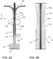
- FIGS. 3A and 3B depicted is a computational fluid dynamics simulation of gas flow within the optical fiber production system 10 with a schematic representation of the upper member 96, the upper tube 34, the nozzle assembly 76, and the slow-cooling treatment device 26.
- the purge gas injected through the inlet 88 has a volume flow rate of 40 SLPM and the inlet 88 has an angle with respect to an X-Y plane of the optical fiber production system 10 of about 20 degrees.
- the purge gas works in synergy with the buoyant flow gas of the slow-cooling treatment device 26 to counteract the boundary layer present proximate the optical fiber 22.
- the inner diameter of the straight portion 96A of the upper member 96 to have a smaller internal diameter than the first portion 92A of the upper tube 34, ambient air is prevented from entering the upper member 96 and the upper tube 34. Further, as explained above, the purge gas which exits the gap 100 may carry the particles with it, thereby removing the particles from the optical fiber production system 10.
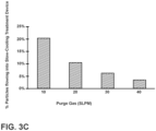
- an increase in the flow rate of the purge gas through the inlet 88 results in a decrease of particles flowing into the slow-cooling treatment device 26.
- particles flowing into the slow-cooling treatment device 26 For example, only those particles that are as close as about 0.1 mm to the optical fiber 22 flow into the slow-cooling treatment device 26. Particles that are further than about 0.1 mm from the fiber surface are deterred from entering the slow-cooling treatment device 26 and purged from the fiber production system 10.
- FIGS. 4A and 4B the depicted simulations were based on a flow rate through the inlet 88 of about 40 SLPM at an angle of about 20° relative to an X-Y plane of the optical fiber production system 10.
- the static pressure on the optical fiber 22 decreases and a percentage of particles entering the slow-cooling treatment device 26 increases.
- the velocity of the purge gas decreases (i.e., due to the same volume of purge gas moving through a larger inlet 88) less particles are stripped from the boundary layer and are removed from the optical fiber production system 10 through the gap 100 and/or the upper member 96.
- FIGS. 5A and 5B the effect of the relationship between the length of the straight portion 96A and the tapered portion 96B of the upper member 96 is shown.
- the straight portion 96A is shorter than the tapered portion 96B (i.e., FIG. 5A ) the purge gas, the stripped boundary layer and the buoyant flow of the slow-cooling treatment device 26 are more spread out along the fiber cutter 104 as opposed to embodiments where the straight portion 96A is of a longer length than the tapered portion 96B of the upper member 96 ( FIG. 5B ).
- the straight portion 96A channels the purge gas, boundary layer and buoyant flow.
- the purge gas works in synergy with the buoyant flow to strip the boundary layer. Furthermore, the simulation shows that a slight improvement to the performance of the purge gas can be realized if the straight portion 96A of the upper member 96 above the gap 100 is extended. The simulation shows that the boundary layer is stripped further away from the upper tube 34. This can be seen from a comparison of the pathlines in FIGS. 5A and 5B . Additionally, a slight reduction in the percentage of particles that flow into the slow-cooling treatment device 26 is also achieved by extending the straight portion 96A of the upper member 96 to 38 mm from about 9.5 mm.
- the temperature delta of the y-axis refers to the difference in temperature of the fiber 22 versus the temperature at which the optical fiber 22 leaves the furnace 14.
- the fiber 22 cools in the slow-cooling treatment device 26 slower than the embodiment of the inlet 88 which is not angled.
- Embodiments of the inlet 88 which are not angled may result in the purge gas entering the slow-cooling treatment device 26 resulting in an increased cooling rate as opposed to the angled embodiment of the inlet 88.
- Such an embodiment may be disadvantageous in cooling the optical fiber 22 faster than a predetermined desirable rate.
- the term "coupled” in all of its forms: couple, coupling, coupled, etc. generally means the joining of two components (electrical or mechanical) directly or indirectly to one another. Such joining may be stationary in nature or movable in nature. Such joining may be achieved with the two components (electrical or mechanical) and any additional intermediate members being integrally formed as a single unitary body with one another or with the two components. Such joining may be permanent in nature, or may be removable or releasable in nature, unless otherwise stated.
Landscapes
- Engineering & Computer Science (AREA)
- Chemical & Material Sciences (AREA)
- Life Sciences & Earth Sciences (AREA)
- General Life Sciences & Earth Sciences (AREA)
- Geochemistry & Mineralogy (AREA)
- Manufacturing & Machinery (AREA)
- Materials Engineering (AREA)
- Organic Chemistry (AREA)
- Physics & Mathematics (AREA)
- Thermal Sciences (AREA)
- Manufacture, Treatment Of Glass Fibers (AREA)
Description
- The present disclosure generally relates to a fiber draw system, and more specifically, to a system for reducing optical fiber breaks in the fiber draw system. The present disclosure further relates to a method of forming an optical fiber.
- Graphite is widely used in fiber draw furnaces due to its high operational temperature. In the hot zone of the furnace, reactions with the furnace wall cause erosion and formation of saturated SiC and SiO vapor. This saturated vapor is cooled as it moves lower in the furnace and away from the hot zone which results in deposition of SiC on the furnace wall. In addition SiO precipitates out and forms SiO particles. These particles typically agglomerate into larger particles which may eventually break loose from the draw furnace wall, get reintroduced into the gas stream and contact the fiber. Large graphite and SiO particles can cause fiber breaks when they adhere to the fiber and create flaws on its surface. Smaller graphite particulate that becomes incorporated into the fiber during the draw process may cause unacceptable product losses due to draw-induced point defects.
- In addition to causing defects in the draw furnace, particulate can be transported out of the draw furnace and into a slow-cooling device due to momentum diffusion from the fiber motion. Due to the small diameter of the slow-cooling treatment device (SCD), these particles are in close proximity to the fiber and may cause additional point defects and fiber breaks as the fiber is still hot and therefore vulnerable to damage. In addition, equipment and process changes may contribute to increased number of particulates that flow into the SCD and increase the potential of breaks.
US 4 030 901 describes a method of drawing an optical fiber including flushing the preform and the fiber with an inert gas flow for protecting the preform and the fiber from contamination. - According to at least one aspect of the present disclosure, there is provided an optical fiber production system according to claim 1.
- According to another aspect of the present disclosure, there is provided a method of forming an optical fiber according to
claim 10. - These and other features, advantages, and objects of the present disclosure will be further understood and appreciated by those skilled in the art by reference to the following specification, claims, and appended drawings.
- In the drawings:
-
FIG. 1 is a schematic diagram illustrating an optical fiber production system having a slow-cooling device, according to one embodiment; -
FIG. 2A is an enhanced cross-sectional view of a top region of the slow-cooling device taken at section IIA ofFIG. 1 , according to one embodiment; -
FIG. 3A is a computational fluid dynamics simulation of a schematic optical fiber production system; -
FIG. 3B is an enlarged view of section IIIB ofFIG. 3A ; -
FIG. 3C is a graph depicting the percentage of particles flowing into the slow-cooling treatment device vs. the purge gas flow rate; -
FIG. 4A is a graph depicting the static pressure on the optical fiber vs. the inlet height for a purge gas volume flow rate of 40 SLPM and 20° inlet angle; -
FIG. 4B is a graph depicting the percentage of particles flowing into the slow-cooling treatment device vs. the inlet height for a purge gas volume flow rate of 40 SLPM and 20 inlet angle; -
FIG. 5A is a computational fluid dynamics simulation of a schematic optical fiber production system; -
FIG. 5B is a computational fluid dynamics simulation of a schematic optical fiber production system; and -
FIG. 6 is a graph illustrating the change in fiber temperature vs. the position of the optical fiber within the slow-cooling treatment device. - Additional features and advantages of the invention will be set forth in the detailed description which follows and will be apparent to those skilled in the art from the description, or recognized by practicing the invention as described in the following description, together with the claims and appended drawings.
- As used herein, the term "and/or," when used in a list of two or more items, means that any one of the listed items can be employed by itself, or any combination of two or more of the listed items can be employed. For example, if a composition is described as containing components A, B, and/or C, the composition can contain A alone; B alone; C alone; A and B in combination; A and C in combination; B and C in combination; or A, B, and C in combination.
- In this document, relational terms, such as first and second, top and bottom, and the like, are used solely to distinguish one entity or action from another entity or action, without necessarily requiring or implying any actual such relationship or order between such entities or actions.
- Referring to
FIG. 1 , an opticalfiber production system 10 is schematically shown, according to one embodiment. Thesystem 10 includes afurnace 14 that may be heated to a temperature of about 2,000°C. A glassoptical fiber preform 18 is placed in thefurnace 14 and fiber is drawn therefrom to create a bareoptical fiber 22. Thepreform 18 may be constructed of any glass or material and may be doped suitable for the manufacture of optical fibers. Once the bareoptical fiber 22 is drawn from thepreform 18, the bareoptical fiber 22 may be cooled in a slow-cooling treatment device 26 ("SCD") shown and described herein as a treatment tube according to one embodiment. The slow-cooling tube ortreatment device 26 is shown distanced from the exit of thefurnace 14, according to one embodiment. However, it should be appreciated thattreatment device 26 could otherwise be coupled to thefurnace 14 or otherwise connected thereto according to other embodiments. - According to various embodiments, the slow-
cooling treatment device 26 is a device downstream from thedraw furnace 14 in which the bareoptical fiber 22 is cooled at a rate that is slower than the cooling rate of thefiber 22 in air at 25°C and a pressure of 1 atm. Apurge device 30 including atube 32, as shown inFIG. 2 , may be positioned above thetreatment device 26 as shown and described herein. Thetreatment device 26 may be positioned proximate to the output or exit port of thefurnace 14 so that the bareoptical fiber 22 enters thetreatment device 26 at a temperature between, for example, about 1,600°C and 2, 100°C. The bareoptical fiber 22 exits thetreatment device 26 at a temperature preferably greater than 500°C. The bareoptical fiber 22 is preferably treated in the slow-cooling treatment device 26 for a time which is sufficient to result in a decrease in attenuation compared to a fiber of identical design which is not treated in thetreatment device 26. For example, foroptical fibers 22 having less than 0.5 wt percent germanium oxide in the core (and also forfibers 22 having cores which are free of germanium oxide), thefiber 22 is preferably treated (slow cooled) within the treatment device during the time period that the fiber temperature is between 1,200°C and 1,800°C, more preferably while the fiber temperature is between 1,200°C and 1,700°C, and even more preferably while the fiber temperature is between 1,300°C and 1,600°C. For examples of theoptical fibers 22 having greater than 0.5 wt percent germanium oxide in the core, thefiber 22 is preferably treated (slow cooled) within the treatment device during the time period that the fiber temperature is between 900°C and 1,600°C, more preferably while the fiber temperature is between 1,000°C and 1,500°C, and even more preferably while the fiber temperature is between 1,000°C and 1,400°C. However, because thetreatment device 26 utilizes lower than atmospheric pressures, these temperature ranges can be achieved in thetreatment device 26 while simultaneously adding an amount of heat which is less than the amount which would otherwise be added if the treatment device was at or above atmospheric pressure. The average cooling rate of thefiber 22 in thetreatment device 26 is defined as the fiber surface temperature at the entry point of thefiber 22 into the treatment device 26 (the fiber entry surface temperature) minus the fiber's surface temperature at an exit point of thefiber 22 out of the treatment device 26 (the fiber exit surface temperature) divided by the total residence time of thefiber 22 in thetreatment device 26. Thetreatment device 26 may be configured to cool the bareoptical fiber 22 as it passes from thefurnace 14 to anexit port 38. - In addition, a
gas inlet 42 is shown for providing an inert gas, shown as G1 inFIG. 1 , as an input to thefurnace 14. The gas G1 may include argon, according to one embodiment, to reduce the amount of ambient air reaching thefurnace 14. According to another embodiment, the inert gas G1 may include nitrogen. It will be understood that more than onegas inlet 42 may be employed at various locations of thefurnace 14 andtreatment device 26. - In the embodiment shown in
FIG. 1 , the bareoptical fiber 22 drawn frompreform 18 passes out through the bottom of thefurnace 14, through thetreatment device 26 out theexit port 38, and, after sufficient cooling, into acoating unit 60. In thecoating unit 60, a primary protective coating layer is applied to an outer surface of the bareoptical fiber 22. After leaving thecoating unit 60, theoptical fiber 22, with a protective layer, can pass through a variety of processing stages within theproduction system 10 such as tractors orrollers 64 and ontofiber storage spool 38. One of therollers 64 may be used to provide the necessary tension on theoptical fiber 22 as it is drawn through the entire system and eventually wound onto astorage spool 38. - Referring now to
FIG. 2A , positioned above the slow-coolingtreatment device 26 is anozzle assembly 76. Thenozzle assembly 76 includes anozzle body 76A and anozzle tube 76B. Anozzle passageway 76C is defined by thenozzle assembly 76 through thenozzle body 76A and thenozzle tube 76B. Positioned above the slow-coolingtreatment device 26 is thepurge device 30. Thepurge device 30 includes thetube 32 and anupper member 96. Thetube 32 includes anupper tube 34 and alower tube 80. Thelower tube 80 is positioned on thenozzle assembly 76 and extends around thenozzle tube 76B. Positioned on top of thelower tube 80 is theupper tube 34. Thenozzle assembly 76 fluidly connects the slow-coolingtreatment device 26 and thepurge device 30. Theupper tube 34 and thelower tube 80 cooperate to define aninlet manifold 84,inlet 88 and atube passageway 92. Thetube passageway 92, according to one embodiment, may be five times greater in length than its internal diameter. As shown inFIG. 2B , theinlet 88 fluidly couples theinlet manifold 84 with thetube passageway 92. Thetube passageway 92 includes afirst portion 92A defined by thelower tube 80 and asecond portion 92B defined by theupper tube 34. Positioned above theupper tube 34 is theupper member 96. Theupper member 96 defines both astraight portion 96A and atapered portion 96B, with the taperedportion 96B being positioned above thestraight portion 96A. Agap 100 is defined between theupper tube 34 and thestraight portion 96A of thepurge device 30. A member passageway 96C is defined by theupper member 96 through thestraight portion 96A and the taperedportion 96B. Positioned above theupper member 96 is afiber cutter 104. Thefiber cutter 104 may be configured to cut theoptical fiber 22 during an end of run sequence of the optical fiber production system 10 (e.g., when the preform 18 (FIG. 1 ) is spent). As is shown, theoptical fiber 22 extends downwardly through thefiber cutter 104, theupper member 96, theupper tube 34, thelower tube 80, thenozzle assembly 76 and into the slow-coolingtreatment device 26. Included within thetube passageway 92 or elsewhere may be a laser micrometer or other device configured to measure a diameter or other property (e.g. temperature, shape, location, etc.) of theoptical fiber 22. - According to various embodiments, the
nozzle assembly 76 may be sized and configured to decrease the flow of a treatment gas present inside of the slow-coolingtreatment device 26 into thetube passageway 92. In operation, the heated treatment gas may tend to float upwards towards theupper tube 34 in such a manner that the slow-coolingtreatment device 26 acts like a chimney. As such, thenozzle passageway 76C of thenozzle assembly 76 is sized to a smaller diameter than that of the slow-coolingtreatment device 26 such that a reduction in the amount of treatment gas escaping into theupper tube 34 may be achieved. - As explained above, the
upper member 96 includes both thestraight portion 96A and the taperedportion 96B. The straight portion and the taperedportion upper member 96. The member passageway 96C, which extends through both thestraight portion 96A and the taperedportion 96B, may likewise be straight and tapered in the corresponding straight andtapered portions tapered portions straight portion 96A of theupper member 96 may be smaller than the internal diameter of thetube passageway 92. The internal diameter of thestraight portion 96A and the member passageway 96C may be between about 7 mm and about 12 mm. The tube passageway 29 may have an internal diameter of between about 6 mm and about 12 mm. Thegap 100 may be used as a camera window or sight port for viewing theoptical fiber 22 during production. Further, as explained in greater detail below, thegap 100 may be used to purge injected gas and furnace particles from theupper tube 34 and generally the opticalfiber production system 10. In the depicted embodiment, thestraight portion 96A of theupper member 96 is shorter than the taperedportion 96B. In other embodiments, thestraight portion 96A may be longer than the taperedportion 96B. The relative lengths of the straight andtapered portions - Referring now to
FIG. 2B , thelower tube 80 is positioned around thenozzle tube 76B. As explained above, theinlet manifold 84 is fluidly coupled with thetube passageway 92 through theinlet 88. Theinlet manifold 84 extends around thetube passageway 92 in a toroidal fashion. Theinlet manifold 84 is configured to receive purge gas which is to be passed into thetube passageway 92 through theinlet 88 and against theoptical fiber 22. Theinlet manifold 84 may create a laminar flow of the purge gas. The toroidal shape of theinlet manifold 84 allows for the substantially uniform distribution of the purge gas to theinlet 88. Theinlet 88, as depicted, is defined by an interface between thelower tube 80 and theupper tube 34. As such, theinlet 88 extends fully around a circumference of thetube passageway 92. It will be understood that theinlet 88 may be a continuous, or discontinuous, structure. For example, theinlet 88 may include a plurality of holes, slots or a combination thereof around the circumference of thetube passageway 92. Theinlet 88 may have a height, of between about 0.1 mm to about 10.0 mm, or between about 0.25 mm to about 3.0 mm, or between about 0.5 mm to about 2.5 mm. According to various embodiments, theinlet 88 may be angled with respect to an X-Y horizontal plane of the opticalfiber production system 10. For example, the angle of theinlet 88 may be between about 0° and about 40°, about 10° to about 35°, with respect to an X-Y plane of the opticalfiber production system 10. In a specific example, the angle of theinlet 88 may be about 20°. In some embodiments, theinlet 88 is angled upwardly. By angling theinlet 88 upward, the injection of the purge gas toward and against theoptical fiber 22 is in a direction generally opposite the drawing direction (the fiber draw direction downward in a Z-direction) of theoptical fiber 22. It will be understood that the angle of theinlet 88 may vary with location around the circumference of thetube passageway 92. Theinlet 88 may inject the purge gas at a volume flow rate of between about 0.1 standard liters per minute (SLPM) and about 80 SLPM, or between about 10 SLPM and about 40 SLPM. It will be understood that the height of theinlet 88 and the volume flow rate of purge gas supplied to theinlet 88 may be altered to achieve a desired static gas pressure on theoptical fiber 22. The static pressure is generated by the purge gas impinging on theoptical fiber 22. According to various embodiments, injection of the purge gas from theinlet 88 contacts thefiber 22 and strips a boundary layer of gases proximate thefiber 22. As explained in greater detail above and below, the boundary layer of gases proximate theoptical fiber 22 may contain particulates from thefurnace 14. The purge gas injected from theinlet 88 strips the boundary layer and particulates from thefiber 22 and ejects the boundary layer gases and particulates through thegap 100 or to the ambient environment above the taperedportion 96B of theupper portion 96. Put another way, thepurge device 30 is configured to inject a purge gas into thepassageway 92 through theinlet 88 and against theoptical fiber 22 such that the purge gas disrupts a boundary layer of gas present along theoptical fiber 22. According to various embodiments, the injection of the purge gas disrupts the boundary layer of gas present along theoptical fiber 22 sufficiently to result in a reduction of particles present in the boundary layer from flowing into the slow-coolingtreatment device 26. - The
nozzle passageway 76C is fluidly coupled with thetube passageway 92. Thenozzle passageway 76C may be tapered proximate thetube passageway 92 such that thenozzle passageway 76C has a smaller internal diameter than thetube passageway 92. In angled embodiments of theinlet 88, injection of the gas in an upward, or Z-direction, through thetube passageway 92 may result in the generation of low pressure within thefirst portion 92A of thetube passageway 92. The low pressure, and a high temperature of the process gases of the slow-coolingtreatment device 26, may result in a buoyant flow of process gases within the slow-cooling treatment device 26 (FIG. 2A ) moving into thetube passageway 92. As such, in embodiments, thenozzle passageway 76C hasa smaller internal diameter than thetube passageway 92 advantageously decreasing a "chimney" effect, or the buoyant flow of the processed gases from the slow-coolingtreatment device 26 into thetube passageway 92. - Referring now to
FIGS. 2A and 2B , in operation, as theoptical fiber 22 is drawn through the opticalfiber production system 10, a portion of the atmosphere furnace gases of thefurnace 14 follows along and outside of theoptical fiber 22 as the boundary layer. As explained above, SiO particles generated in thefurnace 14 may be present in the boundary layer. The movement of theoptical fiber 22 downward from thefurnace 14 and into theupper tube 34 may draw the boundary layer and the particles into the slow-coolingtreatment device 26. Presence of the particles on the surface of theoptical fiber 22 while in the slow-coolingtreatment device 26 may result in the formation of stress concentrators and weak points on thefiber 22. Accordingly, as explained above, theinlet 88 is configured to inject the purge gas into thetube passageway 92 and onto theoptical fiber 22. Injection of the purge gas through theinlet 88 may be of a sufficient volume and pressure such that the boundary layer, and any associated particles, following theoptical fiber 22 are blown off of theoptical fiber 22 and moved toward a top of theupper tube 34 and removed from the opticalfiber production system 10. For example, the furnace atmosphere and its associated particles may be purged from the opticalfiber production system 10 through thegap 100, out a top of the taperedportion 96B of theupper member 96, or combinations thereof. - As explained above, in various embodiments, the
straight portion 96A of theupper member 96 may have a smaller internal diameter than an internal diameter of theupper tube 34. The smaller internal diameter of thestraight portion 96A relative to theupper tube 34 may result in a majority of the furnace atmosphere, particles, and gas injected from theinlet 88 to be expelled through thegap 100. Further, by designing the internal diameter of thetube passageway 92 to be larger than thestraight portion 96A of theupper member 96, ambient air and/or latent environment particles may be prevented from entering into theupper member 96 or theupper tube 34 through thegap 100. In other words, a possible point of Venturi effect may be eliminated such that there is a net out-flux of the purge gas through thegap 100. As such, ambient air and particles do not enter the opticalfiber protection system 10 and cause potential possible fiber break locations. In addition, in embodiments where theinlet 88 is angled with respect to an X-Y plane of the opticalfiber production system 10, the movement of purge gas upwards through theupper tube 34 may result in the buoyant flow of process gas from within the slow-coolingtreatment device 26 into theupper tube 34. The purge gas injected through theinlet 88 and the buoyant flow drawn from the slow-coolingtreatment device 26 may synergistically cooperate to strip the boundary layer and its particles upwards away from the slow-coolingtreatment device 26 and through theupper tube 34 towards thegap 100. The synergistic action of the purge gas and buoyant flow may result in a significant reduction of the particles that flow into the slow-coolingtreatment device 26. - Use of the presently disclosed optical
fiber production system 10 may result in the attainment of a number of advantages. First, use of theinlet 88 allows for particles to be removed from the opticalfiber production system 10 prior to their entrance into the slow-coolingtreatment device 26. As explained above, removal of particles from the slow-coolingtreatment device 26 may reduce the adherence of the particles to theoptical fiber 22 thereby resulting in an increased yield of usableoptical fiber 22 per process run. Second, use of theinlet 88, theupper member 96 and theupper tube 34 may allow for particle removal efficiency in excess of 90%. Third, the purge gas may prevent the entrance of contaminants (e.g., glass shards, particles, debris) from entering the slow-coolingtreatment device 26. For example, during the production of theoptical fiber 22, contaminants may enter the opticalfiber production system 10. Use of the purge gas and the buoyant flow may prevent the entrance of these contaminants into the slow-coolingtreatment device 26. Fourth, the use of a smaller internal diameter of thestraight portion 96A of theupper member 96 may reduce the entrance of ambient air into thefurnace 14. Reduction in the amount of ambient air entering thefurnace 14 may reduce the production of SiO particles within the furnace 14 (i.e., due to less oxygen being present in the furnace 14). - Referring now to
FIGS. 3A and 3B , depicted is a computational fluid dynamics simulation of gas flow within the opticalfiber production system 10 with a schematic representation of theupper member 96, theupper tube 34, thenozzle assembly 76, and the slow-coolingtreatment device 26. In the depicted simulation, the purge gas injected through theinlet 88 has a volume flow rate of 40 SLPM and theinlet 88 has an angle with respect to an X-Y plane of the opticalfiber production system 10 of about 20 degrees. As can be seen, the purge gas works in synergy with the buoyant flow gas of the slow-coolingtreatment device 26 to counteract the boundary layer present proximate theoptical fiber 22. As can be seen in the enhanced view inFIG. 3B , by designing the inner diameter of thestraight portion 96A of theupper member 96 to have a smaller internal diameter than thefirst portion 92A of theupper tube 34, ambient air is prevented from entering theupper member 96 and theupper tube 34. Further, as explained above, the purge gas which exits thegap 100 may carry the particles with it, thereby removing the particles from the opticalfiber production system 10. - Referring now to
FIG. 3C , as can be seen, an increase in the flow rate of the purge gas through theinlet 88 results in a decrease of particles flowing into the slow-coolingtreatment device 26. For example, only those particles that are as close as about 0.1 mm to theoptical fiber 22 flow into the slow-coolingtreatment device 26. Particles that are further than about 0.1 mm from the fiber surface are deterred from entering the slow-coolingtreatment device 26 and purged from thefiber production system 10. - Referring now to
FIGS. 4A and 4B , the depicted simulations were based on a flow rate through theinlet 88 of about 40 SLPM at an angle of about 20° relative to an X-Y plane of the opticalfiber production system 10. As can be seen, with an increasinginlet 88 size, the static pressure on theoptical fiber 22 decreases and a percentage of particles entering the slow-coolingtreatment device 26 increases. In other words, as the velocity of the purge gas decreases (i.e., due to the same volume of purge gas moving through a larger inlet 88) less particles are stripped from the boundary layer and are removed from the opticalfiber production system 10 through thegap 100 and/or theupper member 96. As is apparent fromFIGS. 4A and 4B , a reasonable compromise between static pressure and size of theinlet 88 is achieved by a 2.54 mmtall inlet 88 as the percentage of particles entering the slow-coolingtreatment device 26 is much lower than in the absence of the device (e.g., about 9% vs. about 43%). - Referring now to
FIGS. 5A and 5B , the effect of the relationship between the length of thestraight portion 96A and the taperedportion 96B of theupper member 96 is shown. As can be seen, in embodiments where thestraight portion 96A is shorter than the taperedportion 96B (i.e.,FIG. 5A ) the purge gas, the stripped boundary layer and the buoyant flow of the slow-coolingtreatment device 26 are more spread out along thefiber cutter 104 as opposed to embodiments where thestraight portion 96A is of a longer length than the taperedportion 96B of the upper member 96 (FIG. 5B ). In other words, thestraight portion 96A channels the purge gas, boundary layer and buoyant flow. It can be seen that the purge gas works in synergy with the buoyant flow to strip the boundary layer. Furthermore, the simulation shows that a slight improvement to the performance of the purge gas can be realized if thestraight portion 96A of theupper member 96 above thegap 100 is extended. The simulation shows that the boundary layer is stripped further away from theupper tube 34. This can be seen from a comparison of the pathlines inFIGS. 5A and 5B . Additionally, a slight reduction in the percentage of particles that flow into the slow-coolingtreatment device 26 is also achieved by extending thestraight portion 96A of theupper member 96 to 38 mm from about 9.5 mm. - Referring now to
FIG. 6 , depicted is the change in temperature for theoptical fiber 22 as it relates to an axial position of thefiber 22 within the slow-coolingtreatment device 26. The temperature delta of the y-axis refers to the difference in temperature of thefiber 22 versus the temperature at which theoptical fiber 22 leaves thefurnace 14. As can be seen in the angled embodiment of theinlet 88, thefiber 22 cools in the slow-coolingtreatment device 26 slower than the embodiment of theinlet 88 which is not angled. Embodiments of theinlet 88 which are not angled may result in the purge gas entering the slow-coolingtreatment device 26 resulting in an increased cooling rate as opposed to the angled embodiment of theinlet 88. Such an embodiment may be disadvantageous in cooling theoptical fiber 22 faster than a predetermined desirable rate. - For purposes of this disclosure, the term "coupled" (in all of its forms: couple, coupling, coupled, etc.) generally means the joining of two components (electrical or mechanical) directly or indirectly to one another. Such joining may be stationary in nature or movable in nature. Such joining may be achieved with the two components (electrical or mechanical) and any additional intermediate members being integrally formed as a single unitary body with one another or with the two components. Such joining may be permanent in nature, or may be removable or releasable in nature, unless otherwise stated.
Claims (14)
- An optical fiber production system (10), comprising:a purge device (30), the purge device comprising a tube (32) defining a passageway (92) and an inlet (88), wherein the purge device is configured to inject a purge gas through the inlet and against the optical fiber; andcharacterized in that the system further comprises a slow-cooling device (26) and a nozzle assembly (76) arranged to fluidly connect the purge device (30) and the slow-cooling device (26), wherein the nozzle assembly defines a nozzle passageway, the nozzle passageway having a smaller diameter than a diameter of the passageway (92), wherein the purge device (30) is positioned above the slow-cooling device, and the slow cooling device and the purge device are arranged to receive an optical fiber (22) extending through the slow-cooling device and the purge device.
- The system (10) of claim 1, wherein the injection of the purge gas disrupts a boundary layer of gas present along the optical fiber sufficiently to result in a reduction of particles present in the boundary layer from flowing into the slow-cooling device (26).
- The system of claim 2, wherein the purge gas has a flow rate through the inlet of between about 10 SLPM and about 40 SLPM.
- The system of any of claims 1 to 3, wherein the inlet is continuous around a circumference of the tube.
- The system (10) of any of claims 1 to 4, wherein the inlet (88) has an angle with respect to an X-Y plane of the optical fiber production system (10) of greater than about 0° and less than about 40°.
- The system (10) of any of claims 1 to 5, wherein the inlet (88) has a height of between about 0.1 mm and about 10.0 mm.
- The system (10) of claim 2, wherein the injection of the purge gas disrupts the boundary layer of gas present along the optical fiber sufficiently to result in a reduction of particles present in the boundary layer from flowing into the slow-cooling device (26).
- The system of claim 7, wherein the inlet has an angle with respect to an X-Y plane of the optical fiber production system of greater than about 0° and less than about 40°.
- The system of claim 7 or claim 8, wherein the inlet is configured to inject a purge gas into the passageway in a direction generally opposite to a direction the optical fiber is drawn.
- A method of forming an optical fiber (22), comprising:providing a tube (32) and a nozzle assembly (76) positioned over a slow-cooling treatment device (26), the tube defining a passageway (92) through which an optical fiber is drawn and an inlet (88), wherein a diameter of the nozzle assembly is smaller than a diameter of the passageway (92);heating an optical fiber preform (18);drawing an optical fiber (22) from the preform;passing the optical fiber (22) through the tube (32) and the nozzle assembly (76); andinjecting a purge gas through the inlet (88) toward the optical fiber (22).
- The method of claim 10, further comprising the step: drawing a purge gas within the slow-cooling treatment device (26) into the tube (32).
- The method of claim 10 or claim 11, wherein the inlet (88) has an angle with respect to an X-Y plane of the optical fiber production system (10) of between about 0° and about 40°.
- The method of any of claims 10 to 12, wherein the purge gas has a flow rate through the inlet (88) of between about 10 SLPM and about 40 SLPM.
- The method of any of claims 10 to 13, wherein the injection of the purge gas toward the optical fiber is in a direction generally opposite the drawing direction of the optical fiber.
Applications Claiming Priority (2)
| Application Number | Priority Date | Filing Date | Title |
|---|---|---|---|
| US201662411084P | 2016-10-21 | 2016-10-21 | |
| PCT/US2017/057526 WO2018075852A1 (en) | 2016-10-21 | 2017-10-20 | Purge device for an optical fiber draw system |
Publications (2)
| Publication Number | Publication Date |
|---|---|
| EP3529217A1 EP3529217A1 (en) | 2019-08-28 |
| EP3529217B1 true EP3529217B1 (en) | 2024-03-06 |
Family
ID=60263046
Family Applications (1)
| Application Number | Title | Priority Date | Filing Date |
|---|---|---|---|
| EP17794517.7A Active EP3529217B1 (en) | 2016-10-21 | 2017-10-20 | Purge device for an optical fiber draw system |
Country Status (6)
| Country | Link |
|---|---|
| US (1) | US10773990B2 (en) |
| EP (1) | EP3529217B1 (en) |
| JP (1) | JP7068291B2 (en) |
| CN (1) | CN109890770B (en) |
| DK (1) | DK3529217T3 (en) |
| WO (1) | WO2018075852A1 (en) |
Families Citing this family (6)
| Publication number | Priority date | Publication date | Assignee | Title |
|---|---|---|---|---|
| US11237323B2 (en) * | 2017-02-28 | 2022-02-01 | Corning Incorporated | Methods and systems for controlling air flow through an annealing furnace during optical fiber production |
| CN111995231A (en) * | 2020-09-03 | 2020-11-27 | 江苏亨通光纤科技有限公司 | Drawing equipment and method for deep fluorine-doped capillary tube for beam combiner |
| CN114368124A (en) * | 2020-10-15 | 2022-04-19 | 郑州天河通信科技有限公司 | A online impurity sweeps structure for optical cable production |
| US12623949B2 (en) * | 2021-10-29 | 2026-05-12 | Corning Incorporated | Optical fiber draw production systems, pressure devices and methods applying pressure to optical fiber |
| US20230159372A1 (en) * | 2021-11-22 | 2023-05-25 | Corning Incorporated | Optical fiber forming apparatus |
| US20250197272A1 (en) * | 2022-06-21 | 2025-06-19 | Sumitomo Electric Industries, Ltd. | Optical fiber manufacturing method |
Family Cites Families (20)
| Publication number | Priority date | Publication date | Assignee | Title |
|---|---|---|---|---|
| US4030901A (en) | 1976-07-19 | 1977-06-21 | Bell Telephone Laboratories, Incorporated | Method for drawing fibers |
| JPH0459631A (en) * | 1990-06-27 | 1992-02-26 | Sumitomo Electric Ind Ltd | How to draw optical fiber |
| CA2168830A1 (en) * | 1995-03-23 | 1996-09-24 | John Steele Abbott Iii | Method and apparatus for coating fibers |
| US6345519B1 (en) | 1996-10-25 | 2002-02-12 | Corning Incorporated | Method of reducing break sources in drawn fibers by active oxidation of contaminants in a reducing atmosphere |
| JPH11116264A (en) * | 1997-10-15 | 1999-04-27 | Hitachi Cable Ltd | Optical fiber drawing method and drawing apparatus |
| US5974838A (en) | 1998-07-07 | 1999-11-02 | Alcatel | Optical fiber graphite furnace featuring an automatic shutter door system for feeding an optical preform |
| DE19900375A1 (en) | 1999-01-08 | 2000-07-13 | Alcatel Sa | Device for pulling a fiber |
| US6381990B1 (en) | 1999-02-26 | 2002-05-07 | Corning Incorporated | Draw furnace sealing assembly and method |
| FR2815399B1 (en) | 2000-10-18 | 2003-01-03 | Air Liquide | PROCESS AND PLANT FOR PURIFICATION AND RECYCLING OF HELIUM AND THEIR APPLICATION TO THE MANUFACTURE OF OPTICAL FIBERS |
| US20030200772A1 (en) * | 2002-04-30 | 2003-10-30 | Foster John D. | Methods and apparatus for forming optical fiber |
| JP4155001B2 (en) * | 2002-11-05 | 2008-09-24 | 住友電気工業株式会社 | Optical fiber manufacturing method and manufacturing apparatus |
| US20040107736A1 (en) * | 2002-12-09 | 2004-06-10 | Alcatel | Pure upflow furnace |
| US20070022786A1 (en) * | 2003-04-28 | 2007-02-01 | Foster John D | Methods and apparatus for forming heat treated optical fiber |
| JP4459858B2 (en) * | 2005-05-19 | 2010-04-28 | 株式会社フジクラ | Optical fiber strand manufacturing method and optical fiber strand manufacturing apparatus |
| US7861557B2 (en) * | 2005-12-29 | 2011-01-04 | Silica Tech, Llc | Plasma torch for making synthetic silica |
| CN101533122B (en) * | 2009-04-27 | 2010-08-04 | 中天科技光纤有限公司 | Preparation method of single-mode optical fiber for high-strength large-disc long submarine cable |
| CN101767930B (en) * | 2010-02-05 | 2011-10-26 | 中天科技光纤有限公司 | High-speed wire drawing device for optical fiber production process and high-speed wire drawing method thereof |
| JP5672763B2 (en) | 2010-05-07 | 2015-02-18 | 住友電気工業株式会社 | Optical fiber drawing method and apparatus |
| JP2012082089A (en) * | 2010-10-08 | 2012-04-26 | Hitachi Cable Ltd | Method for manufacturing optical fiber |
| CN201857344U (en) * | 2010-11-02 | 2011-06-08 | 中天科技光纤有限公司 | Lampblack sweeping and collecting device for optical fiber drawing tower |
-
2017
- 2017-10-19 US US15/787,956 patent/US10773990B2/en active Active
- 2017-10-20 CN CN201780065380.9A patent/CN109890770B/en active Active
- 2017-10-20 EP EP17794517.7A patent/EP3529217B1/en active Active
- 2017-10-20 WO PCT/US2017/057526 patent/WO2018075852A1/en not_active Ceased
- 2017-10-20 DK DK17794517.7T patent/DK3529217T3/en active
- 2017-10-20 JP JP2019521105A patent/JP7068291B2/en not_active Expired - Fee Related
Also Published As
| Publication number | Publication date |
|---|---|
| WO2018075852A1 (en) | 2018-04-26 |
| EP3529217A1 (en) | 2019-08-28 |
| DK3529217T3 (en) | 2024-04-02 |
| US10773990B2 (en) | 2020-09-15 |
| CN109890770A (en) | 2019-06-14 |
| US20180111871A1 (en) | 2018-04-26 |
| JP2019532903A (en) | 2019-11-14 |
| JP7068291B2 (en) | 2022-05-16 |
| CN109890770B (en) | 2022-07-08 |
Similar Documents
| Publication | Publication Date | Title |
|---|---|---|
| US10773990B2 (en) | Purge device for an optical fiber draw system | |
| EP2576464B1 (en) | Method for producing optical fiber using linear non-contact fiber centering | |
| US4673427A (en) | Method of and device for drawing an optical fiber from a solid preform consisting substantially of SiO2 and doped SiO2 | |
| EP3589589B1 (en) | Method and system for controlling air flow through an annealing furnace during optical fiber production | |
| EP3347314B1 (en) | Method for producing an optical fiber with low fictive temperature | |
| KR20130117654A (en) | Method for producing optical fiber at reduced pressure | |
| US20190241459A1 (en) | Gas reclamation system for optical fiber production | |
| CN108349781B (en) | Method for manufacturing optical fiber and optical fiber | |
| AU741066B2 (en) | Method and apparatus for cooling optical fibers | |
| EP1243567A1 (en) | Optical fiber producing method | |
| JPS5957927A (en) | Optical fiber production using plasma torch | |
| KR20050084174A (en) | Method and apparatus for making optical fibres | |
| NL2006962C2 (en) | DEVICE AND METHOD FOR MANUFACTURING AN OPTICAL FORM. | |
| JP2000128566A (en) | Method and apparatus for manufacturing optical fiber | |
| DE60311630T2 (en) | Method and furnace for drawing an optical fiber from a preform | |
| NL2025663B1 (en) | Particle exhaust apparatus for optical fiber draw furnace | |
| WO2021126533A1 (en) | Methods and systems for processing optical fiber | |
| CN205687797U (en) | Optical fibre parent material stretch device | |
| US20230406752A1 (en) | Apparatuses and methods for processing optical fiber | |
| JP6578733B2 (en) | Glass tube manufacturing method and glass tube manufacturing apparatus | |
| NL2024696B1 (en) | Methods and systems for processing optical fiber | |
| NL1024943C2 (en) | Method for manufacturing an optical fiber. | |
| KR100746793B1 (en) | Device for preventing oxidation of heating element | |
| EP4436932A1 (en) | Optical fiber forming apparatus | |
| JPH0292838A (en) | Heating furnace for drawing optical fiber |
Legal Events
| Date | Code | Title | Description |
|---|---|---|---|
| STAA | Information on the status of an ep patent application or granted ep patent |
Free format text: STATUS: UNKNOWN |
|
| STAA | Information on the status of an ep patent application or granted ep patent |
Free format text: STATUS: THE INTERNATIONAL PUBLICATION HAS BEEN MADE |
|
| PUAI | Public reference made under article 153(3) epc to a published international application that has entered the european phase |
Free format text: ORIGINAL CODE: 0009012 |
|
| STAA | Information on the status of an ep patent application or granted ep patent |
Free format text: STATUS: REQUEST FOR EXAMINATION WAS MADE |
|
| 17P | Request for examination filed |
Effective date: 20190516 |
|
| AK | Designated contracting states |
Kind code of ref document: A1 Designated state(s): AL AT BE BG CH CY CZ DE DK EE ES FI FR GB GR HR HU IE IS IT LI LT LU LV MC MK MT NL NO PL PT RO RS SE SI SK SM TR |
|
| AX | Request for extension of the european patent |
Extension state: BA ME |
|
| DAV | Request for validation of the european patent (deleted) | ||
| DAX | Request for extension of the european patent (deleted) | ||
| STAA | Information on the status of an ep patent application or granted ep patent |
Free format text: STATUS: EXAMINATION IS IN PROGRESS |
|
| 17Q | First examination report despatched |
Effective date: 20201222 |
|
| GRAP | Despatch of communication of intention to grant a patent |
Free format text: ORIGINAL CODE: EPIDOSNIGR1 |
|
| STAA | Information on the status of an ep patent application or granted ep patent |
Free format text: STATUS: GRANT OF PATENT IS INTENDED |
|
| INTG | Intention to grant announced |
Effective date: 20230926 |
|
| P01 | Opt-out of the competence of the unified patent court (upc) registered |
Effective date: 20231205 |
|
| GRAS | Grant fee paid |
Free format text: ORIGINAL CODE: EPIDOSNIGR3 |
|
| GRAA | (expected) grant |
Free format text: ORIGINAL CODE: 0009210 |
|
| STAA | Information on the status of an ep patent application or granted ep patent |
Free format text: STATUS: THE PATENT HAS BEEN GRANTED |
|
| AK | Designated contracting states |
Kind code of ref document: B1 Designated state(s): AL AT BE BG CH CY CZ DE DK EE ES FI FR GB GR HR HU IE IS IT LI LT LU LV MC MK MT NL NO PL PT RO RS SE SI SK SM TR |
|
| REG | Reference to a national code |
Ref country code: GB Ref legal event code: FG4D |
|
| REG | Reference to a national code |
Ref country code: CH Ref legal event code: EP |
|
| REG | Reference to a national code |
Ref country code: IE Ref legal event code: FG4D |
|
| REG | Reference to a national code |
Ref country code: DE Ref legal event code: R096 Ref document number: 602017079797 Country of ref document: DE |
|
| REG | Reference to a national code |
Ref country code: DK Ref legal event code: T3 Effective date: 20240325 |
|
| REG | Reference to a national code |
Ref country code: NL Ref legal event code: FP |
|
| REG | Reference to a national code |
Ref country code: LT Ref legal event code: MG9D |
|
| PG25 | Lapsed in a contracting state [announced via postgrant information from national office to epo] |
Ref country code: LT Free format text: LAPSE BECAUSE OF FAILURE TO SUBMIT A TRANSLATION OF THE DESCRIPTION OR TO PAY THE FEE WITHIN THE PRESCRIBED TIME-LIMIT Effective date: 20240306 |
|
| PG25 | Lapsed in a contracting state [announced via postgrant information from national office to epo] |
Ref country code: GR Free format text: LAPSE BECAUSE OF FAILURE TO SUBMIT A TRANSLATION OF THE DESCRIPTION OR TO PAY THE FEE WITHIN THE PRESCRIBED TIME-LIMIT Effective date: 20240607 |
|
| PG25 | Lapsed in a contracting state [announced via postgrant information from national office to epo] |
Ref country code: RS Free format text: LAPSE BECAUSE OF FAILURE TO SUBMIT A TRANSLATION OF THE DESCRIPTION OR TO PAY THE FEE WITHIN THE PRESCRIBED TIME-LIMIT Effective date: 20240606 Ref country code: HR Free format text: LAPSE BECAUSE OF FAILURE TO SUBMIT A TRANSLATION OF THE DESCRIPTION OR TO PAY THE FEE WITHIN THE PRESCRIBED TIME-LIMIT Effective date: 20240306 |
|
| PG25 | Lapsed in a contracting state [announced via postgrant information from national office to epo] |
Ref country code: ES Free format text: LAPSE BECAUSE OF FAILURE TO SUBMIT A TRANSLATION OF THE DESCRIPTION OR TO PAY THE FEE WITHIN THE PRESCRIBED TIME-LIMIT Effective date: 20240306 |
|
| PG25 | Lapsed in a contracting state [announced via postgrant information from national office to epo] |
Ref country code: RS Free format text: LAPSE BECAUSE OF FAILURE TO SUBMIT A TRANSLATION OF THE DESCRIPTION OR TO PAY THE FEE WITHIN THE PRESCRIBED TIME-LIMIT Effective date: 20240606 Ref country code: NO Free format text: LAPSE BECAUSE OF FAILURE TO SUBMIT A TRANSLATION OF THE DESCRIPTION OR TO PAY THE FEE WITHIN THE PRESCRIBED TIME-LIMIT Effective date: 20240606 Ref country code: LT Free format text: LAPSE BECAUSE OF FAILURE TO SUBMIT A TRANSLATION OF THE DESCRIPTION OR TO PAY THE FEE WITHIN THE PRESCRIBED TIME-LIMIT Effective date: 20240306 Ref country code: HR Free format text: LAPSE BECAUSE OF FAILURE TO SUBMIT A TRANSLATION OF THE DESCRIPTION OR TO PAY THE FEE WITHIN THE PRESCRIBED TIME-LIMIT Effective date: 20240306 Ref country code: GR Free format text: LAPSE BECAUSE OF FAILURE TO SUBMIT A TRANSLATION OF THE DESCRIPTION OR TO PAY THE FEE WITHIN THE PRESCRIBED TIME-LIMIT Effective date: 20240607 Ref country code: FI Free format text: LAPSE BECAUSE OF FAILURE TO SUBMIT A TRANSLATION OF THE DESCRIPTION OR TO PAY THE FEE WITHIN THE PRESCRIBED TIME-LIMIT Effective date: 20240306 Ref country code: ES Free format text: LAPSE BECAUSE OF FAILURE TO SUBMIT A TRANSLATION OF THE DESCRIPTION OR TO PAY THE FEE WITHIN THE PRESCRIBED TIME-LIMIT Effective date: 20240306 Ref country code: BG Free format text: LAPSE BECAUSE OF FAILURE TO SUBMIT A TRANSLATION OF THE DESCRIPTION OR TO PAY THE FEE WITHIN THE PRESCRIBED TIME-LIMIT Effective date: 20240306 |
|
| REG | Reference to a national code |
Ref country code: AT Ref legal event code: MK05 Ref document number: 1663369 Country of ref document: AT Kind code of ref document: T Effective date: 20240306 |
|
| PG25 | Lapsed in a contracting state [announced via postgrant information from national office to epo] |
Ref country code: SE Free format text: LAPSE BECAUSE OF FAILURE TO SUBMIT A TRANSLATION OF THE DESCRIPTION OR TO PAY THE FEE WITHIN THE PRESCRIBED TIME-LIMIT Effective date: 20240306 Ref country code: LV Free format text: LAPSE BECAUSE OF FAILURE TO SUBMIT A TRANSLATION OF THE DESCRIPTION OR TO PAY THE FEE WITHIN THE PRESCRIBED TIME-LIMIT Effective date: 20240306 |
|
| PG25 | Lapsed in a contracting state [announced via postgrant information from national office to epo] |
Ref country code: IS Free format text: LAPSE BECAUSE OF FAILURE TO SUBMIT A TRANSLATION OF THE DESCRIPTION OR TO PAY THE FEE WITHIN THE PRESCRIBED TIME-LIMIT Effective date: 20240706 |
|
| PG25 | Lapsed in a contracting state [announced via postgrant information from national office to epo] |
Ref country code: SM Free format text: LAPSE BECAUSE OF FAILURE TO SUBMIT A TRANSLATION OF THE DESCRIPTION OR TO PAY THE FEE WITHIN THE PRESCRIBED TIME-LIMIT Effective date: 20240306 Ref country code: PT Free format text: LAPSE BECAUSE OF FAILURE TO SUBMIT A TRANSLATION OF THE DESCRIPTION OR TO PAY THE FEE WITHIN THE PRESCRIBED TIME-LIMIT Effective date: 20240708 |
|
| PG25 | Lapsed in a contracting state [announced via postgrant information from national office to epo] |
Ref country code: CZ Free format text: LAPSE BECAUSE OF FAILURE TO SUBMIT A TRANSLATION OF THE DESCRIPTION OR TO PAY THE FEE WITHIN THE PRESCRIBED TIME-LIMIT Effective date: 20240306 Ref country code: EE Free format text: LAPSE BECAUSE OF FAILURE TO SUBMIT A TRANSLATION OF THE DESCRIPTION OR TO PAY THE FEE WITHIN THE PRESCRIBED TIME-LIMIT Effective date: 20240306 |
|
| PG25 | Lapsed in a contracting state [announced via postgrant information from national office to epo] |
Ref country code: AT Free format text: LAPSE BECAUSE OF FAILURE TO SUBMIT A TRANSLATION OF THE DESCRIPTION OR TO PAY THE FEE WITHIN THE PRESCRIBED TIME-LIMIT Effective date: 20240306 |
|
| PG25 | Lapsed in a contracting state [announced via postgrant information from national office to epo] |
Ref country code: PL Free format text: LAPSE BECAUSE OF FAILURE TO SUBMIT A TRANSLATION OF THE DESCRIPTION OR TO PAY THE FEE WITHIN THE PRESCRIBED TIME-LIMIT Effective date: 20240306 |
|
| PG25 | Lapsed in a contracting state [announced via postgrant information from national office to epo] |
Ref country code: SK Free format text: LAPSE BECAUSE OF FAILURE TO SUBMIT A TRANSLATION OF THE DESCRIPTION OR TO PAY THE FEE WITHIN THE PRESCRIBED TIME-LIMIT Effective date: 20240306 |
|
| PG25 | Lapsed in a contracting state [announced via postgrant information from national office to epo] |
Ref country code: SM Free format text: LAPSE BECAUSE OF FAILURE TO SUBMIT A TRANSLATION OF THE DESCRIPTION OR TO PAY THE FEE WITHIN THE PRESCRIBED TIME-LIMIT Effective date: 20240306 Ref country code: SK Free format text: LAPSE BECAUSE OF FAILURE TO SUBMIT A TRANSLATION OF THE DESCRIPTION OR TO PAY THE FEE WITHIN THE PRESCRIBED TIME-LIMIT Effective date: 20240306 Ref country code: RO Free format text: LAPSE BECAUSE OF FAILURE TO SUBMIT A TRANSLATION OF THE DESCRIPTION OR TO PAY THE FEE WITHIN THE PRESCRIBED TIME-LIMIT Effective date: 20240306 Ref country code: PT Free format text: LAPSE BECAUSE OF FAILURE TO SUBMIT A TRANSLATION OF THE DESCRIPTION OR TO PAY THE FEE WITHIN THE PRESCRIBED TIME-LIMIT Effective date: 20240708 Ref country code: PL Free format text: LAPSE BECAUSE OF FAILURE TO SUBMIT A TRANSLATION OF THE DESCRIPTION OR TO PAY THE FEE WITHIN THE PRESCRIBED TIME-LIMIT Effective date: 20240306 Ref country code: IS Free format text: LAPSE BECAUSE OF FAILURE TO SUBMIT A TRANSLATION OF THE DESCRIPTION OR TO PAY THE FEE WITHIN THE PRESCRIBED TIME-LIMIT Effective date: 20240706 Ref country code: EE Free format text: LAPSE BECAUSE OF FAILURE TO SUBMIT A TRANSLATION OF THE DESCRIPTION OR TO PAY THE FEE WITHIN THE PRESCRIBED TIME-LIMIT Effective date: 20240306 Ref country code: CZ Free format text: LAPSE BECAUSE OF FAILURE TO SUBMIT A TRANSLATION OF THE DESCRIPTION OR TO PAY THE FEE WITHIN THE PRESCRIBED TIME-LIMIT Effective date: 20240306 Ref country code: AT Free format text: LAPSE BECAUSE OF FAILURE TO SUBMIT A TRANSLATION OF THE DESCRIPTION OR TO PAY THE FEE WITHIN THE PRESCRIBED TIME-LIMIT Effective date: 20240306 |
|
| REG | Reference to a national code |
Ref country code: DE Ref legal event code: R097 Ref document number: 602017079797 Country of ref document: DE |
|
| PLBE | No opposition filed within time limit |
Free format text: ORIGINAL CODE: 0009261 |
|
| STAA | Information on the status of an ep patent application or granted ep patent |
Free format text: STATUS: NO OPPOSITION FILED WITHIN TIME LIMIT |
|
| 26N | No opposition filed |
Effective date: 20241209 |
|
| PG25 | Lapsed in a contracting state [announced via postgrant information from national office to epo] |
Ref country code: SI Free format text: LAPSE BECAUSE OF FAILURE TO SUBMIT A TRANSLATION OF THE DESCRIPTION OR TO PAY THE FEE WITHIN THE PRESCRIBED TIME-LIMIT Effective date: 20240306 |
|
| REG | Reference to a national code |
Ref country code: CH Ref legal event code: PL |
|
| PG25 | Lapsed in a contracting state [announced via postgrant information from national office to epo] |
Ref country code: MC Free format text: LAPSE BECAUSE OF FAILURE TO SUBMIT A TRANSLATION OF THE DESCRIPTION OR TO PAY THE FEE WITHIN THE PRESCRIBED TIME-LIMIT Effective date: 20240306 |
|
| PG25 | Lapsed in a contracting state [announced via postgrant information from national office to epo] |
Ref country code: LU Free format text: LAPSE BECAUSE OF NON-PAYMENT OF DUE FEES Effective date: 20241020 Ref country code: BE Free format text: LAPSE BECAUSE OF NON-PAYMENT OF DUE FEES Effective date: 20241031 |
|
| PG25 | Lapsed in a contracting state [announced via postgrant information from national office to epo] |
Ref country code: CH Free format text: LAPSE BECAUSE OF NON-PAYMENT OF DUE FEES Effective date: 20241031 |
|
| REG | Reference to a national code |
Ref country code: BE Ref legal event code: MM Effective date: 20241031 |
|
| PGFP | Annual fee paid to national office [announced via postgrant information from national office to epo] |
Ref country code: DK Payment date: 20250926 Year of fee payment: 9 |
|
| PGFP | Annual fee paid to national office [announced via postgrant information from national office to epo] |
Ref country code: NL Payment date: 20250916 Year of fee payment: 9 |
|
| PGFP | Annual fee paid to national office [announced via postgrant information from national office to epo] |
Ref country code: GB Payment date: 20250911 Year of fee payment: 9 |
|
| PGFP | Annual fee paid to national office [announced via postgrant information from national office to epo] |
Ref country code: FR Payment date: 20250912 Year of fee payment: 9 |
|
| PG25 | Lapsed in a contracting state [announced via postgrant information from national office to epo] |
Ref country code: IE Free format text: LAPSE BECAUSE OF NON-PAYMENT OF DUE FEES Effective date: 20241020 |
|
| PGFP | Annual fee paid to national office [announced via postgrant information from national office to epo] |
Ref country code: DE Payment date: 20250912 Year of fee payment: 9 |
|
| PGFP | Annual fee paid to national office [announced via postgrant information from national office to epo] |
Ref country code: IT Payment date: 20251010 Year of fee payment: 9 |
|
| PG25 | Lapsed in a contracting state [announced via postgrant information from national office to epo] |
Ref country code: CY Free format text: LAPSE BECAUSE OF FAILURE TO SUBMIT A TRANSLATION OF THE DESCRIPTION OR TO PAY THE FEE WITHIN THE PRESCRIBED TIME-LIMIT; INVALID AB INITIO Effective date: 20171020 |
|
| PG25 | Lapsed in a contracting state [announced via postgrant information from national office to epo] |
Ref country code: HU Free format text: LAPSE BECAUSE OF FAILURE TO SUBMIT A TRANSLATION OF THE DESCRIPTION OR TO PAY THE FEE WITHIN THE PRESCRIBED TIME-LIMIT; INVALID AB INITIO Effective date: 20171020 |