EP3528475A1 - A measurement system - Google Patents
A measurement system Download PDFInfo
- Publication number
- EP3528475A1 EP3528475A1 EP19156521.7A EP19156521A EP3528475A1 EP 3528475 A1 EP3528475 A1 EP 3528475A1 EP 19156521 A EP19156521 A EP 19156521A EP 3528475 A1 EP3528475 A1 EP 3528475A1
- Authority
- EP
- European Patent Office
- Prior art keywords
- node
- data transmission
- concentrator
- transmission protocol
- nodes
- Prior art date
- Legal status (The legal status is an assumption and is not a legal conclusion. Google has not performed a legal analysis and makes no representation as to the accuracy of the status listed.)
- Granted
Links
Images


Classifications
-
- H—ELECTRICITY
- H04—ELECTRIC COMMUNICATION TECHNIQUE
- H04L—TRANSMISSION OF DIGITAL INFORMATION, e.g. TELEGRAPHIC COMMUNICATION
- H04L69/00—Network arrangements, protocols or services independent of the application payload and not provided for in the other groups of this subclass
- H04L69/14—Multichannel or multilink protocols
-
- H—ELECTRICITY
- H04—ELECTRIC COMMUNICATION TECHNIQUE
- H04W—WIRELESS COMMUNICATION NETWORKS
- H04W24/00—Supervisory, monitoring or testing arrangements
- H04W24/10—Scheduling measurement reports ; Arrangements for measurement reports
-
- H—ELECTRICITY
- H04—ELECTRIC COMMUNICATION TECHNIQUE
- H04B—TRANSMISSION
- H04B1/00—Details of transmission systems, not covered by a single one of groups H04B3/00 - H04B13/00; Details of transmission systems not characterised by the medium used for transmission
- H04B1/69—Spread spectrum techniques
-
- H—ELECTRICITY
- H04—ELECTRIC COMMUNICATION TECHNIQUE
- H04B—TRANSMISSION
- H04B17/00—Monitoring; Testing
- H04B17/30—Monitoring; Testing of propagation channels
-
- H—ELECTRICITY
- H04—ELECTRIC COMMUNICATION TECHNIQUE
- H04L—TRANSMISSION OF DIGITAL INFORMATION, e.g. TELEGRAPHIC COMMUNICATION
- H04L5/00—Arrangements affording multiple use of the transmission path
- H04L5/003—Arrangements for allocating sub-channels of the transmission path
- H04L5/0044—Allocation of payload; Allocation of data channels, e.g. PDSCH or PUSCH
-
- H—ELECTRICITY
- H04—ELECTRIC COMMUNICATION TECHNIQUE
- H04L—TRANSMISSION OF DIGITAL INFORMATION, e.g. TELEGRAPHIC COMMUNICATION
- H04L67/00—Network arrangements or protocols for supporting network services or applications
- H04L67/50—Network services
- H04L67/56—Provisioning of proxy services
-
- H—ELECTRICITY
- H04—ELECTRIC COMMUNICATION TECHNIQUE
- H04W—WIRELESS COMMUNICATION NETWORKS
- H04W4/00—Services specially adapted for wireless communication networks; Facilities therefor
- H04W4/30—Services specially adapted for particular environments, situations or purposes
- H04W4/38—Services specially adapted for particular environments, situations or purposes for collecting sensor information
-
- H—ELECTRICITY
- H04—ELECTRIC COMMUNICATION TECHNIQUE
- H04W—WIRELESS COMMUNICATION NETWORKS
- H04W52/00—Power management, e.g. Transmission Power Control [TPC] or power classes
- H04W52/02—Power saving arrangements
- H04W52/0209—Power saving arrangements in terminal devices
- H04W52/0225—Power saving arrangements in terminal devices using monitoring of external events, e.g. the presence of a signal
- H04W52/0229—Power saving arrangements in terminal devices using monitoring of external events, e.g. the presence of a signal where the received signal is a wanted signal
-
- H—ELECTRICITY
- H04—ELECTRIC COMMUNICATION TECHNIQUE
- H04W—WIRELESS COMMUNICATION NETWORKS
- H04W52/00—Power management, e.g. Transmission Power Control [TPC] or power classes
- H04W52/02—Power saving arrangements
- H04W52/0209—Power saving arrangements in terminal devices
- H04W52/0261—Power saving arrangements in terminal devices managing power supply demand, e.g. depending on battery level
- H04W52/0274—Power saving arrangements in terminal devices managing power supply demand, e.g. depending on battery level by switching on or off the equipment or parts thereof
- H04W52/028—Power saving arrangements in terminal devices managing power supply demand, e.g. depending on battery level by switching on or off the equipment or parts thereof switching on or off only a part of the equipment circuit blocks
-
- H—ELECTRICITY
- H04—ELECTRIC COMMUNICATION TECHNIQUE
- H04W—WIRELESS COMMUNICATION NETWORKS
- H04W72/00—Local resource management
- H04W72/04—Wireless resource allocation
- H04W72/044—Wireless resource allocation based on the type of the allocated resource
- H04W72/0446—Resources in time domain, e.g. slots or frames
-
- H—ELECTRICITY
- H04—ELECTRIC COMMUNICATION TECHNIQUE
- H04W—WIRELESS COMMUNICATION NETWORKS
- H04W72/00—Local resource management
- H04W72/04—Wireless resource allocation
- H04W72/044—Wireless resource allocation based on the type of the allocated resource
- H04W72/0453—Resources in frequency domain, e.g. a carrier in FDMA
-
- H—ELECTRICITY
- H04—ELECTRIC COMMUNICATION TECHNIQUE
- H04B—TRANSMISSION
- H04B1/00—Details of transmission systems, not covered by a single one of groups H04B3/00 - H04B13/00; Details of transmission systems not characterised by the medium used for transmission
- H04B1/69—Spread spectrum techniques
- H04B2001/6912—Spread spectrum techniques using chirp
-
- Y—GENERAL TAGGING OF NEW TECHNOLOGICAL DEVELOPMENTS; GENERAL TAGGING OF CROSS-SECTIONAL TECHNOLOGIES SPANNING OVER SEVERAL SECTIONS OF THE IPC; TECHNICAL SUBJECTS COVERED BY FORMER USPC CROSS-REFERENCE ART COLLECTIONS [XRACs] AND DIGESTS
- Y02—TECHNOLOGIES OR APPLICATIONS FOR MITIGATION OR ADAPTATION AGAINST CLIMATE CHANGE
- Y02D—CLIMATE CHANGE MITIGATION TECHNOLOGIES IN INFORMATION AND COMMUNICATION TECHNOLOGIES [ICT], I.E. INFORMATION AND COMMUNICATION TECHNOLOGIES AIMING AT THE REDUCTION OF THEIR OWN ENERGY USE
- Y02D30/00—Reducing energy consumption in communication networks
- Y02D30/70—Reducing energy consumption in communication networks in wireless communication networks
Definitions
- the invention concerns transmission of large amounts of data from one or more communication network nodes with sensors to one or more concentrators and is more particularly directed to transferring data under strict time constraints from nodes attached directly or indirectly to rolling element bearings.
- a rolling element bearing comprises an inner ring, an outer ring and several rolling elements or bodies installed between these two rings. These rolling elements can be balls, rollers or needles.
- a rolling bearing and a rolling element bearing can be, for instance, a ball bearing, a roller bearing or a needle bearing.
- each bearing may be full of sensors to measure anything from temperature to load at different places on and parts of the bearing.
- bearings there might even be sensors within one or more of its rollers.
- Bearings pose one big problem when trying to wirelessly collect all the data that the sensors are producing, bearings are mostly made of steel. Wireless transmission, especially using radio frequencies, and steel do not go well together. That the data transfer rate will go down and the nodes don't have an unlimited buffer space creates a problem. There is still room for improvements.
- An object of the invention is to define a measurement system with an efficient data transfer with low overhead between one or more nodes and one or more corresponding concentrators.
- the aforementioned object is achieved by a measurement system with improved data transmission capabilities to enable efficient data transfers in a radio frequency difficult environment.
- two different data transmission protocols are used, each transmitting within its own radio frequency band.
- the first data transmission protocol is an unsynchronized network where nodes can actively poke a concentrator to get attention.
- the concentrator will then switch the node over to a second data transmission protocol which is a time division multiplexing network at a different frequency band.
- the TDM network is able to selectively and efficiently transfer both small and larger data packets.
- the concentrator is able to have both networks active at the same time.
- a measurement system comprising a concentrator and one or more nodes.
- the concentrator comprises a first transceiver operating in a first radio frequency band with a first data transmission protocol and a second transceiver operating in a second radio frequency band with a second data transmission protocol.
- Each of the one or more nodes comprises a multiband transceiver, one or more sensors and/or means to connect to one or more sensors, and a node controller.
- the multiband transceiver is arranged to be able to switch between the first radio frequency band with the first data transmission protocol and the second radio frequency band with the second data transmission protocol.
- the one or more sensors convert one or more physical magnitudes to electrical sensor signals and/or have means to connect to one or more sensors that convert one or more physical magnitudes to electrical sensor signals.
- the node controller is arranged to via the second data transmission protocol transfer the electrical sensor signals to the concentrator.
- the concentrator further comprises a concentrator controller that is arranged to continuously listen with the first transceiver for status messages from the one or more nodes and when receiving a status message from a node, then sending a message back to that node with instructions to switch communication to the second frequency band together with parameters for that node for the second data transmission protocol.
- the node controller is also arranged to default the multiband transceiver upon reset to the first radio frequency band with the first data transmission protocol and then at predetermined time intervals sending a status message and then wait a predetermined wait time interval for a response.
- the second data transmission protocol is a Time Division Multiplexing transmission protocol.
- all the nodes get a time slot for response.
- individual node requests are implemented and for an individual node request in the second data transmission protocol, the addressed node is the only node during that time frame that gets a time slot and that time slot will be allocated all available time in that time frame.
- those addressed nodes are the only nodes during that time frame that get a time slot and those time slots will use all available time in that time frame and be equally divided between them.
- the measurement system can comprises multiple concentrators in a daisy chain, each concentrator comprises its own nodes. One or more of the multiple concentrators may also be virtual if that would improve the data through put. As the packet length may be limited due to hardware restrictions, it may be useful to have several different concentrator time slots for different sets of nodes, thereby maximizing the efficiency of the data transfer. That is if the number of nodes becomes large, the single node transfer slot becomes large, perhaps larger than the physical limit. It then makes sense to segment the nodes into different concentrator slots, just as if they are daisy-chained. In some embodiments at least some of the sensors are attached directly or indirectly to a bearing part. In some embodiments at least some of the nodes are directly attached to a bearing part.
- FIG. 1 illustrates a block diagram of a measurement system according to the invention.
- there is one concentrator/gateway 100 with three nodes 103, 105, 107.
- Each node 103, 105, 107 has its corresponding sensor(s) 123, 125, 126, 127 being integral with a node in question or connectable to a node in question.
- Each sensor is arranged and meant to be attached either directly or indirectly when in use to an element, such as a part of a rolling element bearing.
- the concentrator 100 comprises two transceivers 111, 112, each suitably with an antenna. In some embodiments a shared multi band antenna can be used by both transceivers 111, 112.
- both or one of the transceivers 111, 112 can have separate transmission and reception antennas.
- One transceiver 111 works in a first radio frequency band with a first data transmission protocol
- the other 112 works in a second radio frequency band with a second data transmission protocol.
- the concentrator can and will in use and being active have both transceivers active for simultaneous use.
- Each of the nodes 103, 105, 107 has a multiband antenna/transceiver 113, 115, 117, each being arranged to be able to switch between the first radio frequency band using the first data transmission protocol and the second radio frequency band using the second data transmission protocol.
- the first and the second radio frequency bands are different, the first and the second data transmission protocols are different.
- the first data transmission protocol is an unsynchronized network, that is the nodes 103, 105, 107 and the concentrator 100 are not synchronized as to when each of the node transceivers 113, 115, 117 can transmit data.
- the concentrator 100 will listen and await a status transmission from one or more of the nodes 103, 105, 107, and then more or less directly thereafter send a command/request back to that node.
- the nodes When the nodes are switched to the first data transmission protocol, they will wake up from sleep mode and transmit a status transmission and then wait a predetermined time for a command/request from the concentrator 100.
- a node If a node does not receive a command/request within the predetermined time limit, it will go back to sleep mode and then after a predetermined sleep mode time delay, repeat the sequence of transmitting a status transmission etc.
- the reason that the nodes are in a sleep modes a large part of the time is that they are most likely very low power devices that are powered by batteries, and by keeping a node in sleep mode as much as possible saves energy.
- the node in question will execute the command/request. According to a first aspect of the invention, this enables the nodes to get the attention of the concentrator via the first data transmission protocol and the system can then add nodes as they come, into the second synchronized data transmission protocol which has a higher effective data transfer rate.
- one command/request is to have the node change from the first data transmission protocol working in the first radio frequency band to the second data transmission protocol working in the second radio frequency band.
- the command/request will then comprise all necessary parameters and synchronization details necessary for the node to move to the second data transmission working in the second radio frequency band.
- the second data transmission protocol is a synchronized network to achieve a greater data pass through as with the unsynchronized first data transmission protocol there is a high chance of collision of data packets.
- the nodes will initiate to the first data transmission protocol working in the first radio frequency band and the nodes will also default to this if, for example, a watchdog trips or the node goes out of synchronization with the other nodes and the concentrator.
- the synchronized second data transmission protocol allocates each node a time slot when it can transmit. More details will follow below.
- FIG. 2 illustrates a datagram 230, a data packet, that can suitably be used both for the first and second data transmission protocols.
- the datagram 230 comprises a header 232, a payload 234 and optionally a Cyclic Redundancy Check (CRC) 236 of the payload 234.
- the header 232 commonly comprises a preamble, source and destination addresses, a size of the payload, a CRC of the header, sequence of the datagram, a time stamp, etc.
- the header 232 comprises at least basic information to get the payload properly to its destination and to tell where it came from.
- the header 232 and the CRC 236 are both overhead, they are the means for the payload 234 to get from A, source address, to B, destination address.
- the overhead is equal to or greater than the payload 234. So if we are able to send packets at a rate of 1000 bytes per second, then the effective data transfer rate is only 500 bytes per second or less. For a second example, we keep the header 232 the same size and if we then increase the payload 234 such that the header 232 only represents 10% of a datagram/packet 230, then with the same rate of 1000 bytes per second we get an effective data transfer rate of 900 bytes per seconds. It will most likely go up even higher since there will be fewer data packets per second and per large set of data, thus the inter packet delays will be fewer as well. That is almost double usable data rate.
- a second aspect of the invention is the ability to change the size of the payload 234 in dependence of capacity availability and data set size.
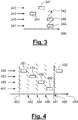
- Figure 3 illustrates an example of a timing diagram of the first data transmission protocol along a timeline 390 divided into timeline 340, 343. 345. 347 rows.
- a first timeline 340 row for packets from a concentrator/gateway, a second timeline 343 row for packets from the first node, a third timeline 345 row for packets from the second node, and a fourth timeline 347 row for packets from the third node.
- the first node will at regular intervals wake up from sleep mode and send out a status packet 344. After sending out the status packet, the node will stay awake for a predetermined listening time to see if there is a concentrator/gateway that responds to the status packet with a command/request packet 341. If there is no command/request packet within the predetermined listening time, then the node goes back to sleep and wakes up again after a predetermined sleep time and repeats the process until the command/request packet 341 comes.
- the concentrator/gateway having two transceivers, one of them listening in the first radio frequency band working according to the first data transmission protocol. When the concentrator receives a status packet from a node it will send a command/request packet back to the node.
- This command/request packet may be a command for the node to switch its multi band transceiver to the second radio frequency band and start communication according to the second data transfer protocol.
- the status requests from the nodes come randomly, in an uncontrolled fashion, thus at times packets collide, this can be seen where a status packet 346 from the second node is sent at exactly the same time as a status packet 348 sent from the third node causing a collision 343 between the two packets, corrupting both packets 346, 348. These packets must thus be resent at different times.
- the units are not synchronized and it is the nodes that take the initiative, randomly and thus prone to collisions that really lowers the transfer rates.
- the units In the second data transmission protocol the units a synchronized, and it is the concentrator/gateway that is in charge.
- Figure 4 illustrates an example of a timing diagram of the second data transmission protocol with small payloads from the nodes along a timeline 491 divided into timeline 450, 453, 455, 457 rows.
- a first timeline 450 row for packets from a concentrator/gateway a second timeline 453 row for packets from the first node, a third timeline 455 row for packets from the second node, and a fourth timeline 457 row for packets from the third node.
- the concentrator will continuously synchronize the nodes so that their individual timing/clocks will not have time to drift to a state where the node cannot communicate within the set constraints. Collisions should not happen.
- the nodes will start 460, 461 to listen for a command/request packet 451, 452 from the concentrator a bit before the expected arrival of the packet 451, 452, this will also give a bit of wiggle room regarding the synchronicity between the devices.
- the concentrator sends a broadcasting command/request 451, for example a status request. Since it goes out as a broadcasting request, all nodes will return in this case with a status packet 454, 456, 458 within their allocated time slots.
- the nodes calculate their individual allocated time slots from the start of the broadcasting request 451.
- the timeframe is suitably sized so that the timeslots allocated for each node is large enough for the individual status packets 454, 456, 458 from the nodes.
- the allocated time slots are not large enough for the measurement data.
- dividing large sets of data into many small packets is not an efficient way of transferring data as the overhead per transferred payload data increases.
- Figure 5 illustrates an example of a timing diagram of the second data transmission protocol with large payload from the second node along a timeline 591 divided into timeline 550, 553, 555, 557 rows.
- a first timeline 550 row for packets from a concentrator/gateway a second timeline 553 row for packets from the first node, a third timeline 555 row for packets from the second node, and a fourth timeline 557 row for packets from the third node.
- the concentrator sends an individual command/request packet 551 to the second node, the other nodes will then keep quiet during this time frame and only the second node sends a large data packet 559. This will keep the total overhead for transferring this data very low.
- the concentrator then send another command/request packet 552 at the beginning of the following time frame.
- FIG. 6 illustrates an example of a timing diagram of the second data transmission protocol with two concentrators/gateways daisy chained, the first concentrator/gateway with a large payload from its first node and the second concentrator/gateway with small payloads from its two nodes. This is illustrated along a timeline 691 divided into timeline 650, 653, 655, 657, 670, 673, 675 rows.
- a first timeline 650 row for packets from a first concentrator/gateway a second timeline 653 row for packets from the first node of the first concentrator, a third timeline 655 row for packets from the second node of the first concentrator, a fourth timeline 657 row for packets from the third node of the first concentrator, a fifth timeline 670 row for packets from a second concentrator/gateway. Illustrated are also the wait times 662, 663, 665, 667, 669 between packets to avoid an overlap/collision between packets.
- the first concentrator sends an individual request packet 651 to its first node, whereby the first node returns a large data packet 659. Since there are no more time slots allocated for the first concentrator, the second concentrator continues with sending a broadcast status request 671 to its nodes, whereby the first and second nodes of the second concentrator return their statuses in corresponding data packets 674, 676 in their corresponding time slots. When the second concentrator runs out of timeslots, then control is returned to the first concentrator which will then send command/request packet 652.
- the invention is based on the basic inventive idea of first using an unsynchronized network for nodes to actively poke a concentrator to get attention, and then the concentrator switching the nodes over to a time division multiplexing network at a different frequency band.
- the TDM network being able to selectively and efficiently transfer both small and larger data packets.
- the concentrator being able to have both networks active at the same time.
- the system can be expanded with daisy-chaining more sets of concentrator frames and their respective nodes either on the same or another concentrator.
- Figure 1 illustrates a block diagram of a measurement system according to the invention
- Figure 2 illustrates a datagram
- Figure 3 illustrates an example of a timing diagram of the first data transmission protocol:
- Figure 4 illustrates an example of a timing diagram of the second data transmission protocol with small payloads from the nodes:
- Figure 5 illustrates an example of a timing diagram of the second data transmission protocol with large payload from the second node:
- Figure 6 illustrates an example of a timing diagram of the second data transmission protocol with two concentrators/gateways are daisy chained, the first concentrator/gateway with a large payload from its first node and the second concentrator/gateway with small payloads from its two nodes:
Landscapes
- Engineering & Computer Science (AREA)
- Signal Processing (AREA)
- Computer Networks & Wireless Communication (AREA)
- Computer Security & Cryptography (AREA)
- Physics & Mathematics (AREA)
- Electromagnetism (AREA)
- Small-Scale Networks (AREA)
- Mobile Radio Communication Systems (AREA)
Abstract
Description
- The invention concerns transmission of large amounts of data from one or more communication network nodes with sensors to one or more concentrators and is more particularly directed to transferring data under strict time constraints from nodes attached directly or indirectly to rolling element bearings.
- A rolling element bearing comprises an inner ring, an outer ring and several rolling elements or bodies installed between these two rings. These rolling elements can be balls, rollers or needles. In the meaning of the invention, a rolling bearing and a rolling element bearing can be, for instance, a ball bearing, a roller bearing or a needle bearing.
- In the field of rolling element bearings, it is known to attach one or more sensors to measure one or more physical parameters and transduce these physical parameters into electrical signals. When it comes to testing bearings in a test center, each bearing may be full of sensors to measure anything from temperature to load at different places on and parts of the bearing. In large size bearings there might even be sensors within one or more of its rollers. Bearings pose one big problem when trying to wirelessly collect all the data that the sensors are producing, bearings are mostly made of steel. Wireless transmission, especially using radio frequencies, and steel do not go well together. That the data transfer rate will go down and the nodes don't have an unlimited buffer space creates a problem. There is still room for improvements.
- An object of the invention is to define a measurement system with an efficient data transfer with low overhead between one or more nodes and one or more corresponding concentrators.
- The aforementioned object is achieved by a measurement system with improved data transmission capabilities to enable efficient data transfers in a radio frequency difficult environment. According to the invention two different data transmission protocols are used, each transmitting within its own radio frequency band. The first data transmission protocol is an unsynchronized network where nodes can actively poke a concentrator to get attention. When a node has the concentrator's attention, the concentrator will then switch the node over to a second data transmission protocol which is a time division multiplexing network at a different frequency band. The TDM network is able to selectively and efficiently transfer both small and larger data packets. The concentrator is able to have both networks active at the same time.
- The aforementioned object is also achieved according to the invention by a measurement system comprising a concentrator and one or more nodes. The concentrator comprises a first transceiver operating in a first radio frequency band with a first data transmission protocol and a second transceiver operating in a second radio frequency band with a second data transmission protocol. Each of the one or more nodes comprises a multiband transceiver, one or more sensors and/or means to connect to one or more sensors, and a node controller. The multiband transceiver is arranged to be able to switch between the first radio frequency band with the first data transmission protocol and the second radio frequency band with the second data transmission protocol. The one or more sensors convert one or more physical magnitudes to electrical sensor signals and/or have means to connect to one or more sensors that convert one or more physical magnitudes to electrical sensor signals. The node controller is arranged to via the second data transmission protocol transfer the electrical sensor signals to the concentrator. According to the invention the concentrator further comprises a concentrator controller that is arranged to continuously listen with the first transceiver for status messages from the one or more nodes and when receiving a status message from a node, then sending a message back to that node with instructions to switch communication to the second frequency band together with parameters for that node for the second data transmission protocol. The node controller is also arranged to default the multiband transceiver upon reset to the first radio frequency band with the first data transmission protocol and then at predetermined time intervals sending a status message and then wait a predetermined wait time interval for a response.
- Suitably the second data transmission protocol is a Time Division Multiplexing transmission protocol. Preferably for a broadcast request in the second data transmission protocol, all the nodes get a time slot for response. In some embodiments individual node requests are implemented and for an individual node request in the second data transmission protocol, the addressed node is the only node during that time frame that gets a time slot and that time slot will be allocated all available time in that time frame. Advantageously for a multi node request in the second data transmission protocol, then those addressed nodes are the only nodes during that time frame that get a time slot and those time slots will use all available time in that time frame and be equally divided between them.
- Preferably a chirp spread spectrum (CSS) radio modulation technology, such as LoRa is used for the hardware and datalink layers. In some embodiments the measurement system can comprises multiple concentrators in a daisy chain, each concentrator comprises its own nodes. One or more of the multiple concentrators may also be virtual if that would improve the data through put. As the packet length may be limited due to hardware restrictions, it may be useful to have several different concentrator time slots for different sets of nodes, thereby maximizing the efficiency of the data transfer. That is if the number of nodes becomes large, the single node transfer slot becomes large, perhaps larger than the physical limit. It then makes sense to segment the nodes into different concentrator slots, just as if they are daisy-chained. In some embodiments at least some of the sensors are attached directly or indirectly to a bearing part. In some embodiments at least some of the nodes are directly attached to a bearing part.
- The different additional enhancements of the measurement system according to the invention can be combined in any desired manner as long as no conflicting features are combined.
- Other advantages of this invention will become apparent from the detailed description.
- The invention will now be described in more detail for explanatory, and in no sense limiting, purposes, with reference to the following figures, in which
- Fig. 1
- illustrates a block diagram of a measurement system according to the invention,
- Fig. 2
- illustrates a datagram,
- Fig. 3
- illustrates an example of a timing diagram of the first data transmission protocol,
- Fig. 4
- illustrates an example of a timing diagram of the second data transmission protocol with small payloads from the nodes,
- Fig. 5
- illustrates an example of a timing diagram of the second data transmission protocol with large payload from the second node,
- Fig. 6
- illustrates an example of a timing diagram of the second data transmission protocol with two concentrators/gateways are daisy chained, the first concentrator/gateway with a large payload from its first node and the second concentrator/gateway with small payloads from its two nodes.
- In order to clarify the method and device according to the invention, some examples of its use will now be described in connection with
Figures 1 to 6 . -
Figure 1 illustrates a block diagram of a measurement system according to the invention. In this example there is one concentrator/gateway 100, with threenodes node concentrator 100 comprises twotransceivers 111, 112, each suitably with an antenna. In some embodiments a shared multi band antenna can be used by bothtransceivers 111, 112. In some other embodiments both or one of thetransceivers 111, 112 can have separate transmission and reception antennas. One transceiver 111 works in a first radio frequency band with a first data transmission protocol, and the other 112 works in a second radio frequency band with a second data transmission protocol. The concentrator can and will in use and being active have both transceivers active for simultaneous use. Each of thenodes transceiver - The first and the second radio frequency bands are different, the first and the second data transmission protocols are different. The first data transmission protocol is an unsynchronized network, that is the
nodes concentrator 100 are not synchronized as to when each of thenode transceivers concentrator 100 will listen and await a status transmission from one or more of thenodes concentrator 100. If a node does not receive a command/request within the predetermined time limit, it will go back to sleep mode and then after a predetermined sleep mode time delay, repeat the sequence of transmitting a status transmission etc. The reason that the nodes are in a sleep modes a large part of the time is that they are most likely very low power devices that are powered by batteries, and by keeping a node in sleep mode as much as possible saves energy. If a command/request from the concentrator is received within the predetermined time, the node in question will execute the command/request. According to a first aspect of the invention, this enables the nodes to get the attention of the concentrator via the first data transmission protocol and the system can then add nodes as they come, into the second synchronized data transmission protocol which has a higher effective data transfer rate. - According to the invention, one command/request is to have the node change from the first data transmission protocol working in the first radio frequency band to the second data transmission protocol working in the second radio frequency band. The command/request will then comprise all necessary parameters and synchronization details necessary for the node to move to the second data transmission working in the second radio frequency band. The second data transmission protocol is a synchronized network to achieve a greater data pass through as with the unsynchronized first data transmission protocol there is a high chance of collision of data packets. Suitably there is a collision detect and then a retransmission at a future time, this steals data throughput.
- The nodes will initiate to the first data transmission protocol working in the first radio frequency band and the nodes will also default to this if, for example, a watchdog trips or the node goes out of synchronization with the other nodes and the concentrator.
- The synchronized second data transmission protocol allocates each node a time slot when it can transmit. More details will follow below.
-
Figure 2 illustrates adatagram 230, a data packet, that can suitably be used both for the first and second data transmission protocols. Thedatagram 230 comprises aheader 232, apayload 234 and optionally a Cyclic Redundancy Check (CRC) 236 of thepayload 234. Theheader 232 commonly comprises a preamble, source and destination addresses, a size of the payload, a CRC of the header, sequence of the datagram, a time stamp, etc. Theheader 232 comprises at least basic information to get the payload properly to its destination and to tell where it came from. Theheader 232 and theCRC 236 are both overhead, they are the means for thepayload 234 to get from A, source address, to B, destination address. If thepayload 234 is the same size in bytes as theheader 232, then the overhead is equal to or greater than thepayload 234. So if we are able to send packets at a rate of 1000 bytes per second, then the effective data transfer rate is only 500 bytes per second or less. For a second example, we keep theheader 232 the same size and if we then increase thepayload 234 such that theheader 232 only represents 10% of a datagram/packet 230, then with the same rate of 1000 bytes per second we get an effective data transfer rate of 900 bytes per seconds. It will most likely go up even higher since there will be fewer data packets per second and per large set of data, thus the inter packet delays will be fewer as well. That is almost double usable data rate. There has also to be a balance between how big the payload capability in the datagram is and the size of the data sets that are to be transported. If one percent of the data sets are 5000 bytes and the other 99% are 50 bytes, then there would be a huge waste, and a very low effective data rate if the payload size would be fixed at 5000 bytes in all the datagrams/packets. Then 99% of the datagrams would only have a payload of one percent of its capability. We are assuming that each data set must be sent separately. A second aspect of the invention is the ability to change the size of thepayload 234 in dependence of capacity availability and data set size. -
Figure 3 illustrates an example of a timing diagram of the first data transmission protocol along atimeline 390 divided intotimeline first timeline 340 row for packets from a concentrator/gateway, asecond timeline 343 row for packets from the first node, athird timeline 345 row for packets from the second node, and afourth timeline 347 row for packets from the third node. - The first node will at regular intervals wake up from sleep mode and send out a
status packet 344. After sending out the status packet, the node will stay awake for a predetermined listening time to see if there is a concentrator/gateway that responds to the status packet with a command/request packet 341. If there is no command/request packet within the predetermined listening time, then the node goes back to sleep and wakes up again after a predetermined sleep time and repeats the process until the command/request packet 341 comes. The concentrator/gateway, having two transceivers, one of them listening in the first radio frequency band working according to the first data transmission protocol. When the concentrator receives a status packet from a node it will send a command/request packet back to the node. This command/request packet may be a command for the node to switch its multi band transceiver to the second radio frequency band and start communication according to the second data transfer protocol. The status requests from the nodes come randomly, in an uncontrolled fashion, thus at times packets collide, this can be seen where astatus packet 346 from the second node is sent at exactly the same time as astatus packet 348 sent from the third node causing acollision 343 between the two packets, corrupting bothpackets - In the first data transmission protocol the units are not synchronized and it is the nodes that take the initiative, randomly and thus prone to collisions that really lowers the transfer rates. In the second data transmission protocol the units a synchronized, and it is the concentrator/gateway that is in charge.
-
Figure 4 illustrates an example of a timing diagram of the second data transmission protocol with small payloads from the nodes along atimeline 491 divided intotimeline first timeline 450 row for packets from a concentrator/gateway, asecond timeline 453 row for packets from the first node, athird timeline 455 row for packets from the second node, and afourth timeline 457 row for packets from the third node. In the second data transmission protocol all the nodes are synchronized with the concentrator/gateway. The concentrator will continuously synchronize the nodes so that their individual timing/clocks will not have time to drift to a state where the node cannot communicate within the set constraints. Collisions should not happen. To lessen the risk of collisions happening, there is some elbow room built into the second data transmission protocol. There are small delays/waittimes request packet packet - In the example shown in
Figure 4 , the concentrator sends a broadcasting command/request 451, for example a status request. Since it goes out as a broadcasting request, all nodes will return in this case with astatus packet broadcasting request 451. The timeframe is suitably sized so that the timeslots allocated for each node is large enough for theindividual status packets - When the nodes are to transfer measurement data from their sensors, the allocated time slots are not large enough for the measurement data. As previously explained, dividing large sets of data into many small packets is not an efficient way of transferring data as the overhead per transferred payload data increases. According to the invention, the enabling a node to use all the timeslots available for all the nodes when a node is individually requested to transfer data.
-
Figure 5 illustrates an example of a timing diagram of the second data transmission protocol with large payload from the second node along atimeline 591 divided intotimeline first timeline 550 row for packets from a concentrator/gateway, asecond timeline 553 row for packets from the first node, athird timeline 555 row for packets from the second node, and afourth timeline 557 row for packets from the third node. There are fewer small delays/waittimes request packet 551 to the second node, the other nodes will then keep quiet during this time frame and only the second node sends alarge data packet 559. This will keep the total overhead for transferring this data very low. The concentrator then send another command/request packet 552 at the beginning of the following time frame. - There are occasions when there needs to be an expansion and the only way to manage this is to introduce more concentrators with their attached nodes with sensors. This can be accomplished according to the invention by daisy chaining the concentrators, all using the same two radio frequency bands.
Figure 6 illustrates an example of a timing diagram of the second data transmission protocol with two concentrators/gateways daisy chained, the first concentrator/gateway with a large payload from its first node and the second concentrator/gateway with small payloads from its two nodes. This is illustrated along atimeline 691 divided intotimeline first timeline 650 row for packets from a first concentrator/gateway, asecond timeline 653 row for packets from the first node of the first concentrator, athird timeline 655 row for packets from the second node of the first concentrator, afourth timeline 657 row for packets from the third node of the first concentrator, afifth timeline 670 row for packets from a second concentrator/gateway. Illustrated are also thewait times - The first concentrator sends an
individual request packet 651 to its first node, whereby the first node returns alarge data packet 659. Since there are no more time slots allocated for the first concentrator, the second concentrator continues with sending abroadcast status request 671 to its nodes, whereby the first and second nodes of the second concentrator return their statuses in correspondingdata packets request packet 652. - The invention is based on the basic inventive idea of first using an unsynchronized network for nodes to actively poke a concentrator to get attention, and then the concentrator switching the nodes over to a time division multiplexing network at a different frequency band. The TDM network being able to selectively and efficiently transfer both small and larger data packets. The concentrator being able to have both networks active at the same time. The system can be expanded with daisy-chaining more sets of concentrator frames and their respective nodes either on the same or another concentrator. The invention is not restricted to the above-described embodiments, but may be varied within the scope of the following claims.
-
Figure 1 illustrates a block diagram of a measurement system according to the invention: - 100
- Concentrator/Gateway,
- 103
- First node,
- 105
- Second node,
- 107
- Third node
- 111
- Antenna/transceiver working in a first radio frequency band with a first data transmission protocol,
- 112
- Antenna/transceiver working in a second radio frequency band with a second data transmission protocol,
- 113
- Multiband antenna/transceiver of the first node, being arranged to be able to switch between the first radio frequency band with the first data transmission protocol and the second radio frequency band with the second data transmission protocol,
- 115
- Multiband antenna/transceiver of the second node, being arranged to be able to switch between the first radio frequency band with the first data transmission protocol and the second radio frequency band with the second data transmission protocol,
- 117
- Multiband antenna/transceiver of the third node, being arranged to be able to switch between the first radio frequency band with the first data transmission protocol and the second radio frequency band with the second data transmission protocol,
- 123
- Sensor of the first node,
- 125
- First sensor of the second node,
- 126
- Second sensor of the second node,
- 127
- Sensor of the third node.
-
Figure 2 illustrates a datagram, - 230
- Datagram,
- 232
- Header, commonly comprising preamble, source and destination addresses, size of payload, CRC of header, time stamp, etc.
- 234
- Payload, the data that is to be transferred from source to destination,
- 236
- Possible CRC of payload.
-
Figure 3 illustrates an example of a timing diagram of the first data transmission protocol: - 340
- Timeline of packets from concentrator/gateway,
- 341
- Command/request packet from the concentrator/gateway,
- 342
- Collision,
- 343
- Timeline of packets from the first node,
- 344
- Status packet from the first node,
- 345
- Timeline of packets from the second node,
- 346
- Status packet from the second node,
- 347
- Timeline of packets from the third node,
- 348
- Status packet from the third node,
- 390
- Timeline.
-
Figure 4 illustrates an example of a timing diagram of the second data transmission protocol with small payloads from the nodes: - 450
- Timeline of packets from the concentrator/gateway,
- 451
- Broadcast command/request packet from the concentrator/gateway to all nodes,
- 452
- Command/request packet from the concentrator/gateway,
- 453
- Timeline of packets from the first node,
- 454
- Status/data packet from the first node,
- 455
- Timeline of packets from the second node,
- 456
- Status/data packet from the second node,
- 457
- Timeline of packets from the third node,
- 458
- Status/data packet from the third node,
- 460
- Synchronized time when nodes go from sleep mode to listening for commands/requests from the concentrator/gateway,
- 461
- Synchronized time when nodes go from sleep mode to listening for commands/requests from the concentrator/gateway,
- 462
- Wait time to avoid overlap/collision,
- 464
- Wait time to avoid overlap/collision,
- 466
- Wait time to avoid overlap/collision,
- 468
- Wait time to avoid overlap/collision,
- 491
- Timeline.
-
Figure 5 illustrates an example of a timing diagram of the second data transmission protocol with large payload from the second node: - 550
- Timeline of packets from the concentrator/gateway,
- 551
- Command/request packet from the concentrator/gateway to the second node,
- 552
- Command/request packet from the concentrator/gateway,
- 553
- Timeline of packets from the first node,
- 555
- Timeline of packets from the second node,
- 559
- Large data packet from the second node,
- 557
- Timeline of packets from the third node,
- 562
- Wait time to avoid overlap/collision,
- 568
- Wait time to avoid overlap/collision,
- 591
- Timeline.
-
Figure 6 illustrates an example of a timing diagram of the second data transmission protocol with two concentrators/gateways are daisy chained, the first concentrator/gateway with a large payload from its first node and the second concentrator/gateway with small payloads from its two nodes: - 650
- Timeline of packets from the first concentrator/gateway,
- 651
- Command/request packet from the first concentrator/gateway to its first node,
- 652
- Command/request packet from the first concentrator/gateway,
- 653
- Timeline of packets from the first node of the first concentrator/gateway,
- 655
- Timeline of packets from the second node of the first concentrator/gateway,
- 657
- Timeline of packets from the third node of the first concentrator/gateway,
- 659
- Large data packet from the first node of the first concentrator/gateway,
- 662
- Wait time to avoid overlap/collision,
- 663
- Wait time to avoid overlap/collision,
- 665
- Wait time to avoid overlap/collision,
- 667
- Wait time to avoid overlap/collision,
- 669
- Wait time to avoid overlap/collision,
- 670
- Timeline of packets from the second concentrator/gateway,
- 671
- Broadcast command/request packet from the second concentrator/gateway to all its nodes,
- 673
- Timeline of packets from the first node of the second concentrator/gateway,
- 674
- Status/data packet from the first node of the second concentrator/gateway,
- 675
- Timeline of packets from the second node of the second concentrator/gateway,
- 676
- Status/data packet from the second node of the second concentrator/gateway,
- 691
- Timeline.
Claims (9)
- A measurement system comprising:- a concentrator comprising;- a first transceiver operating in a first radio frequency band with a first data transmission protocol and;- a second transceiver operating in a second radio frequency band with a second data transmission protocol;- one or more nodes, each node comprisingcharacterized in that the concentrator further comprises a concentrator controller that is arranged to continuously listen with the first transceiver for status messages from the one or more nodes and when receiving a status message from a node, then sending a message back to that node with instructions to switch communication to the second frequency band together with parameters for that node for the second data transmission protocol, and in that the node controller is arranged to default upon reset the multiband transceiver to the first radio frequency band with the first data transmission protocol and then at predetermined time intervals to send a status message and then wait a predetermined wait time interval for a response.- a multiband transceiver being arranged to be able to switch between the first radio frequency band with the first data transmission protocol and the second radio frequency band with the second data transmission protocol;- one or more sensors that convert one or more physical magnitudes to electrical sensor signals or means to connect to one or more sensors that convert one or more physical magnitudes to electrical sensor signals;- a node controller arranged to via the second data transmission protocol transfer the electrical sensor signals to the concentrator;
- The measurement system according to claim 1, characterized in that the second data transmission protocol is a Time Division Multiplex transmission protocol.
- The measurement system according to any previous claim, characterized in that for a broadcast request in the second data transmission protocol, then all the nodes get a time slot for response.
- The measurement system according to any previous claim, characterized in that for an individual node request in the second data transmission protocol, then that addressed node is the only node during that time frame that gets a time slot and that time slot will be allocated all available time in that time frame.
- The measurement system according to any previous claim, characterized in that for a multi node request in the second data transmission protocol, then those addressed nodes are the only nodes during that time frame that get a time slot and those time slots will use all available time in that time frame and be equally divided between them.
- The measurement system according to any previous claim, characterized in that a chirp spread spectrum (CSS) radio modulation technology is used for the hardware and datalink layers.
- The measurement system according to any previous claim, characterized in that the measurement system comprises multiple concentrators in a daisy chain, each concentrator comprises its own nodes.
- The measurement system according to any previous claim, characterized in that at least some of the sensors are attached directly or indirectly to a bearing part.
- The measurement system according to any previous claim, characterized in that that at least some of the nodes are directly attached to a bearing part.
Applications Claiming Priority (1)
| Application Number | Priority Date | Filing Date | Title |
|---|---|---|---|
| DE102018202440.5A DE102018202440A1 (en) | 2018-02-19 | 2018-02-19 | measuring system |
Publications (2)
| Publication Number | Publication Date |
|---|---|
| EP3528475A1 true EP3528475A1 (en) | 2019-08-21 |
| EP3528475B1 EP3528475B1 (en) | 2022-08-03 |
Family
ID=65576113
Family Applications (1)
| Application Number | Title | Priority Date | Filing Date |
|---|---|---|---|
| EP19156521.7A Active EP3528475B1 (en) | 2018-02-19 | 2019-02-11 | A measurement system |
Country Status (6)
| Country | Link |
|---|---|
| US (1) | US10779181B2 (en) |
| EP (1) | EP3528475B1 (en) |
| CN (1) | CN110176967B (en) |
| DE (1) | DE102018202440A1 (en) |
| DK (1) | DK3528475T3 (en) |
| ES (1) | ES2929135T3 (en) |
Families Citing this family (3)
| Publication number | Priority date | Publication date | Assignee | Title |
|---|---|---|---|---|
| CN111628801B (en) * | 2020-05-28 | 2022-02-01 | 维沃移动通信有限公司 | Radio frequency front-end device control method and user equipment |
| CN113011444B (en) * | 2020-12-18 | 2022-05-13 | 浙江大学 | Image identification method based on neural network frequency domain attention mechanism |
| CN113542911A (en) * | 2021-05-20 | 2021-10-22 | 南京欧一机电科技有限公司 | A safe and reliable concentrator |
Citations (1)
| Publication number | Priority date | Publication date | Assignee | Title |
|---|---|---|---|---|
| US20180027490A1 (en) * | 2016-07-25 | 2018-01-25 | Apple Inc. | Wake-Up Radio Assisted WLAN Power Saving Technologies |
Family Cites Families (5)
| Publication number | Priority date | Publication date | Assignee | Title |
|---|---|---|---|---|
| EP1119137B1 (en) * | 2000-01-20 | 2006-08-16 | Lucent Technologies Inc. | Interoperability for bluetooth/IEEE 802.11 |
| MX2008008749A (en) * | 2008-07-04 | 2010-03-01 | Sensa Control Digital S A De C V | Acquisition, control and measurement device. |
| US8219157B2 (en) * | 2009-03-26 | 2012-07-10 | Apple Inc. | Electronic device with shared multiband antenna and antenna diversity circuitry |
| KR101590293B1 (en) * | 2015-01-29 | 2016-02-01 | 세종대학교산학협력단 | Backscatter system including non-power senser node and wireless internet connection method thereof |
| CN105704726B (en) * | 2016-03-11 | 2019-07-23 | 重庆新源创实业股份有限公司 | Adapted telecommunication wireless self-networking method and system based on multi-band fusion |
-
2018
- 2018-02-19 DE DE102018202440.5A patent/DE102018202440A1/en active Pending
-
2019
- 2019-02-11 EP EP19156521.7A patent/EP3528475B1/en active Active
- 2019-02-11 DK DK19156521.7T patent/DK3528475T3/en active
- 2019-02-11 US US16/272,004 patent/US10779181B2/en active Active
- 2019-02-11 ES ES19156521T patent/ES2929135T3/en active Active
- 2019-02-18 CN CN201910119023.7A patent/CN110176967B/en active Active
Patent Citations (1)
| Publication number | Priority date | Publication date | Assignee | Title |
|---|---|---|---|---|
| US20180027490A1 (en) * | 2016-07-25 | 2018-01-25 | Apple Inc. | Wake-Up Radio Assisted WLAN Power Saving Technologies |
Also Published As
| Publication number | Publication date |
|---|---|
| DK3528475T3 (en) | 2022-10-24 |
| US10779181B2 (en) | 2020-09-15 |
| EP3528475B1 (en) | 2022-08-03 |
| ES2929135T3 (en) | 2022-11-25 |
| CN110176967B (en) | 2022-08-12 |
| US20190261205A1 (en) | 2019-08-22 |
| CN110176967A (en) | 2019-08-27 |
| DE102018202440A1 (en) | 2019-08-22 |
Similar Documents
| Publication | Publication Date | Title |
|---|---|---|
| EP2728764B1 (en) | Synchronous access method, and communication device and system in frequency hopping radio communication | |
| US7885251B2 (en) | Real-time wireless sensor network protocol having linear configuration | |
| US9673927B2 (en) | Wireless communication apparatus, wireless communication system, and wireless communication method | |
| KR101542732B1 (en) | Mac protocol for multi-channel wireless networks | |
| US8248989B2 (en) | Wireless network system using cyclic frame | |
| US20030137993A1 (en) | Method of managing time slots in a wireless network through the use of contention groups | |
| US10779181B2 (en) | Measurement system | |
| CN105071831A (en) | Media access control for ultra-wide band communication | |
| JP2002247640A (en) | Method for transmitting a paging message used in a base station of a wireless communication system | |
| Gonga et al. | MobiSense: Power-efficient micro-mobility in wireless sensor networks | |
| Li et al. | A cluster based on-demand multi-channel MAC protocol for wireless multimedia sensor networks | |
| JP2025520151A (en) | Efficient unicast superframe communication | |
| EP3373647B1 (en) | Enhanced network access scheme | |
| Sukor et al. | Performance study of wireless body area network in medical environment | |
| KR101249295B1 (en) | Ad-hoc communication system in the wireless network | |
| JP2006246465A (en) | Radio station and communication method | |
| Goyal et al. | TDMA based delay sensitive and energy efficient protocol for WBAN | |
| US10313991B2 (en) | Implicit exchange of channel information for un-slotted channel hopping networks | |
| Swain et al. | Adv-MMAC: An advertisement based multichannel MAC protocol for wireless sensor networks | |
| Misic et al. | Slave-slave bridging in 802.15. 4 beacon enabled networks | |
| Bernardo et al. | A MAC protocol for mobile wireless sensor networks with bursty traffic | |
| Tyagi et al. | A survey on MAC layer protocols for machine to machine communication | |
| KR100599537B1 (en) | Media access control and physical layer device to reduce power consumption in private wireless network | |
| Meyer et al. | Are group acknowledgements worth anything in IEEE 802.15. 4 DSME: A comparative analysis | |
| Okumura et al. | A broadcast protocol for IEEE 802.15. 4e RIT based Wi-SUN systems |
Legal Events
| Date | Code | Title | Description |
|---|---|---|---|
| PUAI | Public reference made under article 153(3) epc to a published international application that has entered the european phase |
Free format text: ORIGINAL CODE: 0009012 |
|
| STAA | Information on the status of an ep patent application or granted ep patent |
Free format text: STATUS: THE APPLICATION HAS BEEN PUBLISHED |
|
| AK | Designated contracting states |
Kind code of ref document: A1 Designated state(s): AL AT BE BG CH CY CZ DE DK EE ES FI FR GB GR HR HU IE IS IT LI LT LU LV MC MK MT NL NO PL PT RO RS SE SI SK SM TR |
|
| AX | Request for extension of the european patent |
Extension state: BA ME |
|
| STAA | Information on the status of an ep patent application or granted ep patent |
Free format text: STATUS: REQUEST FOR EXAMINATION WAS MADE |
|
| 17P | Request for examination filed |
Effective date: 20200212 |
|
| RBV | Designated contracting states (corrected) |
Designated state(s): AL AT BE BG CH CY CZ DE DK EE ES FI FR GB GR HR HU IE IS IT LI LT LU LV MC MK MT NL NO PL PT RO RS SE SI SK SM TR |
|
| STAA | Information on the status of an ep patent application or granted ep patent |
Free format text: STATUS: EXAMINATION IS IN PROGRESS |
|
| 17Q | First examination report despatched |
Effective date: 20200514 |
|
| RAP3 | Party data changed (applicant data changed or rights of an application transferred) |
Owner name: AKTIEBOLAGET SKF |
|
| REG | Reference to a national code |
Ref country code: DE Ref legal event code: R079 Ref document number: 602019017643 Country of ref document: DE Free format text: PREVIOUS MAIN CLASS: H04L0029080000 Ipc: H04L0067560000 |
|
| GRAP | Despatch of communication of intention to grant a patent |
Free format text: ORIGINAL CODE: EPIDOSNIGR1 |
|
| RIC1 | Information provided on ipc code assigned before grant |
Ipc: H04W 4/38 20180101ALI20220131BHEP Ipc: H04W 52/02 20090101ALI20220131BHEP Ipc: H04L 69/14 20220101ALI20220131BHEP Ipc: H04L 67/56 20220101AFI20220131BHEP |
|
| STAA | Information on the status of an ep patent application or granted ep patent |
Free format text: STATUS: GRANT OF PATENT IS INTENDED |
|
| INTG | Intention to grant announced |
Effective date: 20220310 |
|
| GRAS | Grant fee paid |
Free format text: ORIGINAL CODE: EPIDOSNIGR3 |
|
| GRAA | (expected) grant |
Free format text: ORIGINAL CODE: 0009210 |
|
| STAA | Information on the status of an ep patent application or granted ep patent |
Free format text: STATUS: THE PATENT HAS BEEN GRANTED |
|
| AK | Designated contracting states |
Kind code of ref document: B1 Designated state(s): AL AT BE BG CH CY CZ DE DK EE ES FI FR GB GR HR HU IE IS IT LI LT LU LV MC MK MT NL NO PL PT RO RS SE SI SK SM TR |
|
| REG | Reference to a national code |
Ref country code: AT Ref legal event code: REF Ref document number: 1509670 Country of ref document: AT Kind code of ref document: T Effective date: 20220815 Ref country code: CH Ref legal event code: EP |
|
| REG | Reference to a national code |
Ref country code: DE Ref legal event code: R096 Ref document number: 602019017643 Country of ref document: DE |
|
| REG | Reference to a national code |
Ref country code: IE Ref legal event code: FG4D |
|
| REG | Reference to a national code |
Ref country code: DK Ref legal event code: T3 Effective date: 20221021 |
|
| REG | Reference to a national code |
Ref country code: ES Ref legal event code: FG2A Ref document number: 2929135 Country of ref document: ES Kind code of ref document: T3 Effective date: 20221125 Ref country code: LT Ref legal event code: MG9D |
|
| REG | Reference to a national code |
Ref country code: NL Ref legal event code: MP Effective date: 20220803 |
|
| PG25 | Lapsed in a contracting state [announced via postgrant information from national office to epo] |
Ref country code: SE Free format text: LAPSE BECAUSE OF FAILURE TO SUBMIT A TRANSLATION OF THE DESCRIPTION OR TO PAY THE FEE WITHIN THE PRESCRIBED TIME-LIMIT Effective date: 20220803 Ref country code: RS Free format text: LAPSE BECAUSE OF FAILURE TO SUBMIT A TRANSLATION OF THE DESCRIPTION OR TO PAY THE FEE WITHIN THE PRESCRIBED TIME-LIMIT Effective date: 20220803 Ref country code: PT Free format text: LAPSE BECAUSE OF FAILURE TO SUBMIT A TRANSLATION OF THE DESCRIPTION OR TO PAY THE FEE WITHIN THE PRESCRIBED TIME-LIMIT Effective date: 20221205 Ref country code: NO Free format text: LAPSE BECAUSE OF FAILURE TO SUBMIT A TRANSLATION OF THE DESCRIPTION OR TO PAY THE FEE WITHIN THE PRESCRIBED TIME-LIMIT Effective date: 20221103 Ref country code: NL Free format text: LAPSE BECAUSE OF FAILURE TO SUBMIT A TRANSLATION OF THE DESCRIPTION OR TO PAY THE FEE WITHIN THE PRESCRIBED TIME-LIMIT Effective date: 20220803 Ref country code: LV Free format text: LAPSE BECAUSE OF FAILURE TO SUBMIT A TRANSLATION OF THE DESCRIPTION OR TO PAY THE FEE WITHIN THE PRESCRIBED TIME-LIMIT Effective date: 20220803 Ref country code: LT Free format text: LAPSE BECAUSE OF FAILURE TO SUBMIT A TRANSLATION OF THE DESCRIPTION OR TO PAY THE FEE WITHIN THE PRESCRIBED TIME-LIMIT Effective date: 20220803 Ref country code: FI Free format text: LAPSE BECAUSE OF FAILURE TO SUBMIT A TRANSLATION OF THE DESCRIPTION OR TO PAY THE FEE WITHIN THE PRESCRIBED TIME-LIMIT Effective date: 20220803 |
|
| REG | Reference to a national code |
Ref country code: AT Ref legal event code: MK05 Ref document number: 1509670 Country of ref document: AT Kind code of ref document: T Effective date: 20220803 |
|
| PG25 | Lapsed in a contracting state [announced via postgrant information from national office to epo] |
Ref country code: PL Free format text: LAPSE BECAUSE OF FAILURE TO SUBMIT A TRANSLATION OF THE DESCRIPTION OR TO PAY THE FEE WITHIN THE PRESCRIBED TIME-LIMIT Effective date: 20220803 Ref country code: IS Free format text: LAPSE BECAUSE OF FAILURE TO SUBMIT A TRANSLATION OF THE DESCRIPTION OR TO PAY THE FEE WITHIN THE PRESCRIBED TIME-LIMIT Effective date: 20221203 Ref country code: HR Free format text: LAPSE BECAUSE OF FAILURE TO SUBMIT A TRANSLATION OF THE DESCRIPTION OR TO PAY THE FEE WITHIN THE PRESCRIBED TIME-LIMIT Effective date: 20220803 Ref country code: GR Free format text: LAPSE BECAUSE OF FAILURE TO SUBMIT A TRANSLATION OF THE DESCRIPTION OR TO PAY THE FEE WITHIN THE PRESCRIBED TIME-LIMIT Effective date: 20221104 |
|
| PG25 | Lapsed in a contracting state [announced via postgrant information from national office to epo] |
Ref country code: SM Free format text: LAPSE BECAUSE OF FAILURE TO SUBMIT A TRANSLATION OF THE DESCRIPTION OR TO PAY THE FEE WITHIN THE PRESCRIBED TIME-LIMIT Effective date: 20220803 Ref country code: RO Free format text: LAPSE BECAUSE OF FAILURE TO SUBMIT A TRANSLATION OF THE DESCRIPTION OR TO PAY THE FEE WITHIN THE PRESCRIBED TIME-LIMIT Effective date: 20220803 Ref country code: CZ Free format text: LAPSE BECAUSE OF FAILURE TO SUBMIT A TRANSLATION OF THE DESCRIPTION OR TO PAY THE FEE WITHIN THE PRESCRIBED TIME-LIMIT Effective date: 20220803 Ref country code: AT Free format text: LAPSE BECAUSE OF FAILURE TO SUBMIT A TRANSLATION OF THE DESCRIPTION OR TO PAY THE FEE WITHIN THE PRESCRIBED TIME-LIMIT Effective date: 20220803 |
|
| REG | Reference to a national code |
Ref country code: DE Ref legal event code: R097 Ref document number: 602019017643 Country of ref document: DE |
|
| PG25 | Lapsed in a contracting state [announced via postgrant information from national office to epo] |
Ref country code: SK Free format text: LAPSE BECAUSE OF FAILURE TO SUBMIT A TRANSLATION OF THE DESCRIPTION OR TO PAY THE FEE WITHIN THE PRESCRIBED TIME-LIMIT Effective date: 20220803 Ref country code: EE Free format text: LAPSE BECAUSE OF FAILURE TO SUBMIT A TRANSLATION OF THE DESCRIPTION OR TO PAY THE FEE WITHIN THE PRESCRIBED TIME-LIMIT Effective date: 20220803 |
|
| PLBE | No opposition filed within time limit |
Free format text: ORIGINAL CODE: 0009261 |
|
| STAA | Information on the status of an ep patent application or granted ep patent |
Free format text: STATUS: NO OPPOSITION FILED WITHIN TIME LIMIT |
|
| P01 | Opt-out of the competence of the unified patent court (upc) registered |
Effective date: 20230513 |
|
| PG25 | Lapsed in a contracting state [announced via postgrant information from national office to epo] |
Ref country code: AL Free format text: LAPSE BECAUSE OF FAILURE TO SUBMIT A TRANSLATION OF THE DESCRIPTION OR TO PAY THE FEE WITHIN THE PRESCRIBED TIME-LIMIT Effective date: 20220803 |
|
| 26N | No opposition filed |
Effective date: 20230504 |
|
| PG25 | Lapsed in a contracting state [announced via postgrant information from national office to epo] |
Ref country code: SI Free format text: LAPSE BECAUSE OF FAILURE TO SUBMIT A TRANSLATION OF THE DESCRIPTION OR TO PAY THE FEE WITHIN THE PRESCRIBED TIME-LIMIT Effective date: 20220803 |
|
| PG25 | Lapsed in a contracting state [announced via postgrant information from national office to epo] |
Ref country code: MC Free format text: LAPSE BECAUSE OF FAILURE TO SUBMIT A TRANSLATION OF THE DESCRIPTION OR TO PAY THE FEE WITHIN THE PRESCRIBED TIME-LIMIT Effective date: 20220803 |
|
| REG | Reference to a national code |
Ref country code: CH Ref legal event code: PL |
|
| REG | Reference to a national code |
Ref country code: BE Ref legal event code: MM Effective date: 20230228 |
|
| GBPC | Gb: european patent ceased through non-payment of renewal fee |
Effective date: 20230211 |
|
| PG25 | Lapsed in a contracting state [announced via postgrant information from national office to epo] |
Ref country code: LU Free format text: LAPSE BECAUSE OF NON-PAYMENT OF DUE FEES Effective date: 20230211 Ref country code: LI Free format text: LAPSE BECAUSE OF NON-PAYMENT OF DUE FEES Effective date: 20230228 Ref country code: CH Free format text: LAPSE BECAUSE OF NON-PAYMENT OF DUE FEES Effective date: 20230228 |
|
| REG | Reference to a national code |
Ref country code: IE Ref legal event code: MM4A |
|
| PG25 | Lapsed in a contracting state [announced via postgrant information from national office to epo] |
Ref country code: GB Free format text: LAPSE BECAUSE OF NON-PAYMENT OF DUE FEES Effective date: 20230211 |
|
| PG25 | Lapsed in a contracting state [announced via postgrant information from national office to epo] |
Ref country code: IE Free format text: LAPSE BECAUSE OF NON-PAYMENT OF DUE FEES Effective date: 20230211 Ref country code: GB Free format text: LAPSE BECAUSE OF NON-PAYMENT OF DUE FEES Effective date: 20230211 Ref country code: FR Free format text: LAPSE BECAUSE OF NON-PAYMENT OF DUE FEES Effective date: 20230228 |
|
| PG25 | Lapsed in a contracting state [announced via postgrant information from national office to epo] |
Ref country code: BE Free format text: LAPSE BECAUSE OF NON-PAYMENT OF DUE FEES Effective date: 20230228 |
|
| PG25 | Lapsed in a contracting state [announced via postgrant information from national office to epo] |
Ref country code: IT Free format text: LAPSE BECAUSE OF FAILURE TO SUBMIT A TRANSLATION OF THE DESCRIPTION OR TO PAY THE FEE WITHIN THE PRESCRIBED TIME-LIMIT Effective date: 20220803 |
|
| PG25 | Lapsed in a contracting state [announced via postgrant information from national office to epo] |
Ref country code: BG Free format text: LAPSE BECAUSE OF FAILURE TO SUBMIT A TRANSLATION OF THE DESCRIPTION OR TO PAY THE FEE WITHIN THE PRESCRIBED TIME-LIMIT Effective date: 20220803 |
|
| PG25 | Lapsed in a contracting state [announced via postgrant information from national office to epo] |
Ref country code: BG Free format text: LAPSE BECAUSE OF FAILURE TO SUBMIT A TRANSLATION OF THE DESCRIPTION OR TO PAY THE FEE WITHIN THE PRESCRIBED TIME-LIMIT Effective date: 20220803 |
|
| PG25 | Lapsed in a contracting state [announced via postgrant information from national office to epo] |
Ref country code: CY Free format text: LAPSE BECAUSE OF FAILURE TO SUBMIT A TRANSLATION OF THE DESCRIPTION OR TO PAY THE FEE WITHIN THE PRESCRIBED TIME-LIMIT; INVALID AB INITIO Effective date: 20190211 |
|
| PG25 | Lapsed in a contracting state [announced via postgrant information from national office to epo] |
Ref country code: HU Free format text: LAPSE BECAUSE OF FAILURE TO SUBMIT A TRANSLATION OF THE DESCRIPTION OR TO PAY THE FEE WITHIN THE PRESCRIBED TIME-LIMIT; INVALID AB INITIO Effective date: 20190211 |
|
| PG25 | Lapsed in a contracting state [announced via postgrant information from national office to epo] |
Ref country code: TR Free format text: LAPSE BECAUSE OF FAILURE TO SUBMIT A TRANSLATION OF THE DESCRIPTION OR TO PAY THE FEE WITHIN THE PRESCRIBED TIME-LIMIT Effective date: 20220803 |
|
| PGFP | Annual fee paid to national office [announced via postgrant information from national office to epo] |
Ref country code: ES Payment date: 20260317 Year of fee payment: 8 |
|
| PGFP | Annual fee paid to national office [announced via postgrant information from national office to epo] |
Ref country code: DE Payment date: 20260220 Year of fee payment: 8 Ref country code: DK Payment date: 20260223 Year of fee payment: 8 |