EP3528304A1 - Secondary battery and method for manufacturing same - Google Patents
Secondary battery and method for manufacturing same Download PDFInfo
- Publication number
- EP3528304A1 EP3528304A1 EP18783648.1A EP18783648A EP3528304A1 EP 3528304 A1 EP3528304 A1 EP 3528304A1 EP 18783648 A EP18783648 A EP 18783648A EP 3528304 A1 EP3528304 A1 EP 3528304A1
- Authority
- EP
- European Patent Office
- Prior art keywords
- secondary battery
- temperature
- hot melt
- gasket
- top cap
- Prior art date
- Legal status (The legal status is an assumption and is not a legal conclusion. Google has not performed a legal analysis and makes no representation as to the accuracy of the status listed.)
- Granted
Links
Images



Classifications
-
- H—ELECTRICITY
- H01—ELECTRIC ELEMENTS
- H01M—PROCESSES OR MEANS, e.g. BATTERIES, FOR THE DIRECT CONVERSION OF CHEMICAL ENERGY INTO ELECTRICAL ENERGY
- H01M50/00—Constructional details or processes of manufacture of the non-active parts of electrochemical cells other than fuel cells, e.g. hybrid cells
- H01M50/10—Primary casings; Jackets or wrappings
- H01M50/147—Lids or covers
- H01M50/166—Lids or covers characterised by the methods of assembling casings with lids
- H01M50/171—Lids or covers characterised by the methods of assembling casings with lids using adhesives or sealing agents
-
- H—ELECTRICITY
- H01—ELECTRIC ELEMENTS
- H01M—PROCESSES OR MEANS, e.g. BATTERIES, FOR THE DIRECT CONVERSION OF CHEMICAL ENERGY INTO ELECTRICAL ENERGY
- H01M10/00—Secondary cells; Manufacture thereof
- H01M10/04—Construction or manufacture in general
- H01M10/0422—Cells or battery with cylindrical casing
-
- H—ELECTRICITY
- H01—ELECTRIC ELEMENTS
- H01M—PROCESSES OR MEANS, e.g. BATTERIES, FOR THE DIRECT CONVERSION OF CHEMICAL ENERGY INTO ELECTRICAL ENERGY
- H01M10/00—Secondary cells; Manufacture thereof
- H01M10/04—Construction or manufacture in general
-
- H—ELECTRICITY
- H01—ELECTRIC ELEMENTS
- H01M—PROCESSES OR MEANS, e.g. BATTERIES, FOR THE DIRECT CONVERSION OF CHEMICAL ENERGY INTO ELECTRICAL ENERGY
- H01M10/00—Secondary cells; Manufacture thereof
- H01M10/04—Construction or manufacture in general
- H01M10/049—Processes for forming or storing electrodes in the battery container
-
- H—ELECTRICITY
- H01—ELECTRIC ELEMENTS
- H01M—PROCESSES OR MEANS, e.g. BATTERIES, FOR THE DIRECT CONVERSION OF CHEMICAL ENERGY INTO ELECTRICAL ENERGY
- H01M50/00—Constructional details or processes of manufacture of the non-active parts of electrochemical cells other than fuel cells, e.g. hybrid cells
- H01M50/10—Primary casings; Jackets or wrappings
- H01M50/147—Lids or covers
- H01M50/166—Lids or covers characterised by the methods of assembling casings with lids
- H01M50/167—Lids or covers characterised by the methods of assembling casings with lids by crimping
-
- H—ELECTRICITY
- H01—ELECTRIC ELEMENTS
- H01M—PROCESSES OR MEANS, e.g. BATTERIES, FOR THE DIRECT CONVERSION OF CHEMICAL ENERGY INTO ELECTRICAL ENERGY
- H01M50/00—Constructional details or processes of manufacture of the non-active parts of electrochemical cells other than fuel cells, e.g. hybrid cells
- H01M50/10—Primary casings; Jackets or wrappings
- H01M50/183—Sealing members
- H01M50/186—Sealing members characterised by the disposition of the sealing members
-
- H—ELECTRICITY
- H01—ELECTRIC ELEMENTS
- H01M—PROCESSES OR MEANS, e.g. BATTERIES, FOR THE DIRECT CONVERSION OF CHEMICAL ENERGY INTO ELECTRICAL ENERGY
- H01M50/00—Constructional details or processes of manufacture of the non-active parts of electrochemical cells other than fuel cells, e.g. hybrid cells
- H01M50/10—Primary casings; Jackets or wrappings
- H01M50/183—Sealing members
- H01M50/19—Sealing members characterised by the material
- H01M50/193—Organic material
-
- H—ELECTRICITY
- H01—ELECTRIC ELEMENTS
- H01M—PROCESSES OR MEANS, e.g. BATTERIES, FOR THE DIRECT CONVERSION OF CHEMICAL ENERGY INTO ELECTRICAL ENERGY
- H01M50/00—Constructional details or processes of manufacture of the non-active parts of electrochemical cells other than fuel cells, e.g. hybrid cells
- H01M50/10—Primary casings; Jackets or wrappings
- H01M50/183—Sealing members
- H01M50/19—Sealing members characterised by the material
- H01M50/197—Sealing members characterised by the material having a layered structure
-
- H—ELECTRICITY
- H01—ELECTRIC ELEMENTS
- H01M—PROCESSES OR MEANS, e.g. BATTERIES, FOR THE DIRECT CONVERSION OF CHEMICAL ENERGY INTO ELECTRICAL ENERGY
- H01M2220/00—Batteries for particular applications
- H01M2220/30—Batteries in portable systems, e.g. mobile phone, laptop
-
- Y—GENERAL TAGGING OF NEW TECHNOLOGICAL DEVELOPMENTS; GENERAL TAGGING OF CROSS-SECTIONAL TECHNOLOGIES SPANNING OVER SEVERAL SECTIONS OF THE IPC; TECHNICAL SUBJECTS COVERED BY FORMER USPC CROSS-REFERENCE ART COLLECTIONS [XRACs] AND DIGESTS
- Y02—TECHNOLOGIES OR APPLICATIONS FOR MITIGATION OR ADAPTATION AGAINST CLIMATE CHANGE
- Y02E—REDUCTION OF GREENHOUSE GAS [GHG] EMISSIONS, RELATED TO ENERGY GENERATION, TRANSMISSION OR DISTRIBUTION
- Y02E60/00—Enabling technologies; Technologies with a potential or indirect contribution to GHG emissions mitigation
- Y02E60/10—Energy storage using batteries
-
- Y—GENERAL TAGGING OF NEW TECHNOLOGICAL DEVELOPMENTS; GENERAL TAGGING OF CROSS-SECTIONAL TECHNOLOGIES SPANNING OVER SEVERAL SECTIONS OF THE IPC; TECHNICAL SUBJECTS COVERED BY FORMER USPC CROSS-REFERENCE ART COLLECTIONS [XRACs] AND DIGESTS
- Y02—TECHNOLOGIES OR APPLICATIONS FOR MITIGATION OR ADAPTATION AGAINST CLIMATE CHANGE
- Y02P—CLIMATE CHANGE MITIGATION TECHNOLOGIES IN THE PRODUCTION OR PROCESSING OF GOODS
- Y02P70/00—Climate change mitigation technologies in the production process for final industrial or consumer products
- Y02P70/50—Manufacturing or production processes characterised by the final manufactured product
Definitions
- the present invention relates to a secondary battery and a method for manufacturing the same, and more particularly, to a secondary battery, in which a sealing property is improved, and a method for manufacturing the same.
- Batteries (cells) that generate electric energy through physical or chemical reaction to supply the generated electric energy to the outside are used when AC power to be supplied to the building is not obtained, or DC power is required according to the living environments surrounded by various electric and electronic devices.
- primary batteries and secondary batteries which are chemical batteries using chemical reaction
- the primary batteries are consumable batteries which are collectively referred to as dry batteries.
- secondary batteries are rechargeable batteries that are manufactured by using a material in a redox process between current and a substance is repeatable several times. When the reduction reaction is performed on the material by the current, power is charged, and when the oxidation reaction is performed on the material, power is discharged. Such the charging-discharging is repeatedly performed to generate electricity.
- a lithium ion battery of the secondary batteries is manufactured through the following processes.
- An active material is applied to each of a positive electrode conductive foil and a negative electrode conductive foil at a predetermined thickness, and a separator is disposed between the positive electrode conductive foil and the negative electrode conductive foil, and then, an electrode assembly, in which the positive electrode conductive foil, the separator, and the negative electrode conductive foil are wound several times in a jelly-roll or cylindrical shape, is accommodated into a cylindrical or prismatic can, a pouch, and the like to seal the resultant product, thereby manufacturing the lithium ion battery.
- a non-permeable sealing member for non-aqueous electrochemical cells according to the related art is disclosed in Korean Patent Publication No. 10-2010-0036316 .
- sealing of a gasket part is achieved by pressing and sealing a gasket together with an upper end of a can member through a physical force.
- an object of the prevent invention is to provide a secondary battery, in which a sealing property is improved, and a method for manufacturing the same.
- a secondary battery includes: a can member having an opening; a top cap assembly sealing the opening; a gasket insulating the opening from the top cap assembly; and a hot melt applied to a surface of the gasket, wherein the hot melt has fluidity and viscosity at a predetermined temperature or more and is hardened at a temperature less than the predetermined temperature.
- the predetermined temperature may be a glass transition temperature (Tg).
- the predetermined temperature may be 60°C.
- the hot melt may have an adhesive property at the predetermined temperature or more.
- the hot melt may include a material that repeatedly has a state of having a viscosity at the predetermined temperature or more and a hard state at a temperature less than the predetermined temperature according to the temperature increases and decreases.
- the hot melt may be made of a combination of a thermoplastic resin and a tackifier.
- the hot melt may further include a coupling agent.
- the thermoplastic resin may include a polyester-based resin.
- the tackifier may include at least one or more of a phenol-based resin, a carbon-based resin, and a rosin-based resin.
- the coupling agent may include at least one or more of aminosilane and vinylsilane, which are silicon-based materials.
- a method for manufacturing a secondary battery includes: a preparation step of preparing a can member, a top cap assembly, and a gasket; a coating step of applying a hot melt that is dissolved in an organic solvent to a surface of the gasket; a drying step of drying the gasket to evaporate the organic solvent after the coating step; an assembly step of assembling the cap member and the top cap assembly with the gasket after the drying step to manufacture a secondary battery; and an activation step of activating the secondary battery, wherein, in the activation step, the hot melt is changed in phase according to a temperature change, and the gasket airtightly adheres to the can member and the top cap assembly by the hot melt that is changed in phase.
- the activation step may include: a room-temperature aging process of aging the secondary battery at room temperature; a high-temperature aging process of aging the secondary battery under a temperature environment of 60°C or more that is higher than that of the room-temperature aging process; and a charging/discharging process of charging and discharging the secondary battery under a temperature environment of 60°C or less that is lower than that of the high-temperature aging process after the high-temperature aging process.
- the hot melt may be in a hard state during the room-temperature aging process, be changed in phase to a material having fluidity and viscosity during the high-temperature aging process, and be hardened again at room temperature.
- the organic solvent may include at least one or more of toluene, xylene, and methyl ethyl ketone.
- the gasket may adhere to the can member and the top cap assembly to improve the sealing property.
- the coupling agent may be contained in the hot melt applied to the gasket to improve the adhesive property and enhance the waterproof property.
- the hot melt may be applied to the gasket to increase the chemical resistance.
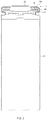
- FIG. 1 is a perspective view of a secondary battery according to an embodiment of the present invention
- FIG. 2 is a cross-sectional view taken along line A-A of FIG. 1 .
- a secondary battery includes a can member 10, in which an opening 11 is defined, a top cap assembly 20 sealing the opening 11, a gasket 30 insulating the opening 11 and the top cap assembly 20 from each other, and a hot melt 40 applied to a surface of the gasket 30.
- the can member 10 may be a container made of a metal material and having a shape that is opened substantially upward in a cylindrical or prismatic type lithium ion secondary battery.
- the can member 10 may be made of aluminum (Al) or steel plated with nickel (Ni) which is light and easy to cope with corrosion.
- the can member 10 serves as a container for an electrode assembly and an electrolyte. After the electrode assembly is inserted into the can member 10 through the opened upper end of the can member 10, i.e., the opening 11 defined in the upper end of the can member 10, the opening 11 defined in the upper end of the can member 10 is sealed by the top cap assembly 20.
- the gasket 30 is made of an insulation material. An inner circumference of the gasket 30 is closely attached to the top cap assembly 20 to insulate the can member 10 and the top cap assembly 20 from each other, and an outer circumference of the gasket 30 is closely attached to the opening 11 of the can member 10.
- the can member 10 further include a crimping part 10a for bending an opening-side circumference that is the upper end of the can member 10 to fix the top cap assembly 20 sealing the opening 11 of the can member 10.
- the gasket 30 may be installed between the opening 11 of the can member 10 and the top cap assembly 20 so as to be pressed and fixed to the can member 10 together with the top cap assembly 20 by using a crimping part 10a.
- the hot melt 40 is applied to the surface of the gasket 30.
- the hot melt 40 may be selectively applied to the entire surface or a portion of the surface of the gasket 30.
- the hot melt 40 may be made of a combination of a thermoplastic resin and a tackifier and may further contain a coupling agent to improve adhesive property and enhance a waterproof property.
- the thermoplastic resin may include a polyester-based resin.
- the tackifier may be at least one or more of a phenol-based resin, a carbon-based resin, a rosin-based resin and the like and have a property having viscosity or adhesion.
- the coupling agent may be at least one or more of aminosilane, vinylsilane, and the like, which are silicon-based materials, and be a material capable of being bound to oxide of a metal surface.
- the oxide binding on the inner surface of the metal can member 10 may significantly improve the adhesive property and sealability.
- the hot melt 40 may have a property of having fluidity and viscosity while being melted at a glass transition temperature Tg of 60°C or more.
- the hot melt 40 may be maintained in a hard state at room temperature and have the adhesive property while being melted at the glass transition temperature that is a predetermined temperature.
- the hot melt 40 may have a material property that is capable of repeatedly having the state of having a viscosity at the glass transition temperature or more and the hard state below the glass transition temperature according to the temperature increases and decreases.
- FIG. 3 is a partial enlarged view illustrating a main part of allowing a gasket to adhere to a top cap assembly and a can member in FIG. 2 .
- the inner circumference of the gasket 30 may adhere to the top cap assembly 20, and the outer circumference of the gasket 30 may adhere to the can member 10.
- the hot melt 40 may be applied to the surface of the gasket 30 at room temperature. Since the hot melt 40 does not have the fluidity and viscosity at room temperature, the hot melt 40 may be only applied to the surface of the gasket 30 and thus may not significantly affect the adhesion of the gasket 30.
- the gasket 30 may be assembled and installed between the can member 10 and the top cap assembly 20 in the state in which the hard hot melt 40 is applied to the gasket 30. After being assembled, the gasket 30 may be put into an activation process in a state of being pressed.
- the temperature increases at a temperature of 60°C or more that is the glass transition temperature and then decreases again at room temperature. In this process, the adhesion between the gasket 30 and the can member 10 may be completed.
- a predetermined temperature and pressure may be applied to the hot melt 40 at the same time to allow the hot melt 40 to have the fluidity so that the hot melt 40 is permeated and filled into a fine gap between the coupled surfaces.
- the gap may be a fine gap formed between the coupled portions or may be a fine gap 10b, a groove, a scratch, an unevenness, or the like, which is formed in the coupled surface of the opening 10 of the can member.
- the hot melt 40 since the hot melt 40 has the viscosity, the hot melt 40 may serve as a sticky medium between the gasket 30 and the top cap assembly 20 or between the gasket 30 and the can member 10.
- the hot melt 40 may be hardened again.
- the hot melt 40 may be permeated into the gap between the coupled surfaces and then hardened.
- the gasket 30 and the top cap assembly 20 or the gasket 30 and the can member 10 may be very airtightly and strongly coupled to each other by the hot melt 40.
- oxide coupling may be additionally achieved to obtain additional effects such as improvement in adhesion and enhancement in waterproof property.
- FIG. 4 is a flowchart illustrating a method for manufacturing a secondary battery according to an embodiment of the prevent invention.
- a method for manufacturing a secondary battery includes a preparation step (S1), a coating step (S2), a drying step (S3), an assembly step (S4), and an activation step (S5).
- the preparation step (S1) may be a step of preparing a can member 10, a top cap assembly 20, and a gasket 30.
- the coating step (S2) may be a step of applying a hot melt 40 to a surface of the gasket 30.
- the hot melt 40 may be melted by using an organic solvent made of at least one or more of toluene, xylene, methyl ethyl ketone, and the like so that the hard hot melt 40 is applied to a surface of the gasket 30 at room temperature.
- the melted solution may be applied to the surface of the gasket 30.
- the drying step (S3) may be a step of drying the gasket 30 to evaporate the organic solvent after the coating step (S2). After the organic solvent is evaporated, only the hot melt 40 may remain on the surface of the gasket 30 to form a coating layer of the hot melt 40 on the surface of the gasket 30.
- the assembly step (S4) may be a step of assembling a top cap assembly 20 and the gasket 30 with a can member 10 in which an electrode assembly and an electrolyte are accommodated after the drying step (S3) to manufacture a secondary battery.
- the activation step (S5) may be a step of activating the manufactured secondary battery.
- the activation step (S5) may include a room-temperature aging process of aging the secondary battery at room temperature, a high-temperature aging process of aging the secondary battery under a temperature environment 60°C or more that is higher than that of the room-temperature aging process, and a charging/discharging process of charging and discharging the secondary battery under a temperature environment of 60°C or less that is lower than that of the high-temperature aging process after the high-temperature aging process.
- the hot melt 40 may be in the hard state during the room-temperature aging process and be changed in phase to a material having fluidity and viscosity during the high-temperature aging process and then be hardened again during the charging/discharging process and at room temperature.
- the adhesion between the gasket and the can member may be completed.
- the process of completing the adhesion according to the temperature change is the same as described above, and thus, its description will be omitted.
- the method for assembling the second battery according to an embodiment of the present invention may have a great advantage in that the hot melt 40 applied to the gasket 30 strongly adhere to the can member 10 and the top cap assembly 20 while the activation step (S5) of the secondary battery is performed without a separate additional process to improve sealing property. Since the activation step is the existing process, it is unnecessary to separately perform a heating process for the adhesion of the gasket.
- the gasket may adhere to the can member and the top cap assembly to improve the sealing property.
- the coupling agent may be contained in the hot melt applied to the gasket to improve the adhesive property and enhance the waterproof property.
- the hot melt may be applied to the gasket to completely block the moisture permeation and significantly suppress the corrosion, thereby improving chemical resistance.
Landscapes
- Chemical & Material Sciences (AREA)
- Chemical Kinetics & Catalysis (AREA)
- Electrochemistry (AREA)
- General Chemical & Material Sciences (AREA)
- Engineering & Computer Science (AREA)
- Manufacturing & Machinery (AREA)
- Sealing Battery Cases Or Jackets (AREA)
- Secondary Cells (AREA)
Abstract
Description
- The present application claims the benefit of the priority of Korean Patent Application No.
2017-0048646, filed on April 14, 2017 - The present invention relates to a secondary battery and a method for manufacturing the same, and more particularly, to a secondary battery, in which a sealing property is improved, and a method for manufacturing the same.
- Batteries (cells) that generate electric energy through physical or chemical reaction to supply the generated electric energy to the outside are used when AC power to be supplied to the building is not obtained, or DC power is required according to the living environments surrounded by various electric and electronic devices.
- Among such batteries, primary batteries and secondary batteries, which are chemical batteries using chemical reaction, are being generally used. The primary batteries are consumable batteries which are collectively referred to as dry batteries. Also, secondary batteries are rechargeable batteries that are manufactured by using a material in a redox process between current and a substance is repeatable several times. When the reduction reaction is performed on the material by the current, power is charged, and when the oxidation reaction is performed on the material, power is discharged. Such the charging-discharging is repeatedly performed to generate electricity.
- A lithium ion battery of the secondary batteries is manufactured through the following processes. An active material is applied to each of a positive electrode conductive foil and a negative electrode conductive foil at a predetermined thickness, and a separator is disposed between the positive electrode conductive foil and the negative electrode conductive foil, and then, an electrode assembly, in which the positive electrode conductive foil, the separator, and the negative electrode conductive foil are wound several times in a jelly-roll or cylindrical shape, is accommodated into a cylindrical or prismatic can, a pouch, and the like to seal the resultant product, thereby manufacturing the lithium ion battery.
- A non-permeable sealing member for non-aqueous electrochemical cells according to the related art is disclosed in Korean Patent Publication No.
10-2010-0036316 - In the secondary battery according to the related art, sealing of a gasket part is achieved by pressing and sealing a gasket together with an upper end of a can member through a physical force. As a result, there is a problem that leakage occurs due to dimensions of parts or an assembly process deviation, or performance is deteriorated due to moisture penetration.
- Therefore, the present invention has been made to solve the abovementioned problem, and an object of the prevent invention is to provide a secondary battery, in which a sealing property is improved, and a method for manufacturing the same.
- A secondary battery according to an embodiment of the present invention includes: a can member having an opening; a top cap assembly sealing the opening; a gasket insulating the opening from the top cap assembly; and a hot melt applied to a surface of the gasket, wherein the hot melt has fluidity and viscosity at a predetermined temperature or more and is hardened at a temperature less than the predetermined temperature.
- The predetermined temperature may be a glass transition temperature (Tg).
- The predetermined temperature may be 60°C.
- The hot melt may have an adhesive property at the predetermined temperature or more.
- The hot melt may include a material that repeatedly has a state of having a viscosity at the predetermined temperature or more and a hard state at a temperature less than the predetermined temperature according to the temperature increases and decreases.
- The hot melt may be made of a combination of a thermoplastic resin and a tackifier.
- The hot melt may further include a coupling agent.
- The thermoplastic resin may include a polyester-based resin.
- The tackifier may include at least one or more of a phenol-based resin, a carbon-based resin, and a rosin-based resin.
- The coupling agent may include at least one or more of aminosilane and vinylsilane, which are silicon-based materials.
- A method for manufacturing a secondary battery according to an embodiment of the present invention includes: a preparation step of preparing a can member, a top cap assembly, and a gasket; a coating step of applying a hot melt that is dissolved in an organic solvent to a surface of the gasket; a drying step of drying the gasket to evaporate the organic solvent after the coating step; an assembly step of assembling the cap member and the top cap assembly with the gasket after the drying step to manufacture a secondary battery; and an activation step of activating the secondary battery, wherein, in the activation step, the hot melt is changed in phase according to a temperature change, and the gasket airtightly adheres to the can member and the top cap assembly by the hot melt that is changed in phase.
- The activation step may include: a room-temperature aging process of aging the secondary battery at room temperature; a high-temperature aging process of aging the secondary battery under a temperature environment of 60°C or more that is higher than that of the room-temperature aging process; and a charging/discharging process of charging and discharging the secondary battery under a temperature environment of 60°C or less that is lower than that of the high-temperature aging process after the high-temperature aging process.
- The hot melt may be in a hard state during the room-temperature aging process, be changed in phase to a material having fluidity and viscosity during the high-temperature aging process, and be hardened again at room temperature.
- The organic solvent may include at least one or more of toluene, xylene, and methyl ethyl ketone.
- According to the present invention, the gasket may adhere to the can member and the top cap assembly to improve the sealing property.
- According to the present invention, the coupling agent may be contained in the hot melt applied to the gasket to improve the adhesive property and enhance the waterproof property.
- According to the present invention, the hot melt may be applied to the gasket to increase the chemical resistance.
-
-
FIG. 1 is a perspective view of a secondary battery according to an embodiment of the present invention. -
FIG. 2 is a cross-sectional view taken along line A-A ofFIG. 1 . -
FIG. 3 is a partial enlarged view illustrating a main part of allowing a gasket to adhere to a top cap assembly and a can member inFIG. 2 . -
FIG. 4 is a flowchart illustrating a method for manufacturing a secondary battery according to an embodiment of the prevent invention. - Hereinafter, a secondary battery and a method for manufacturing the same according to exemplary embodiments of the present invention will be described in detail with reference to the accompanying drawings.
- Terms or words used in the specification and claims should not be construed as limited to a lexical meaning, and should be understood as appropriate notions by the inventor based on that he/she is able to define terms to describe his/her invention in the best way to be seen by others. Therefore, embodiments and drawings described herein are simply exemplary and not exhaustive, and it will be understood that various equivalents may be made to take the place of the embodiments.
- In the drawings, the dimension of each of components or a specific portion constituting the component is exaggerated, omitted, or schematically illustrated for convenience in description and clarity. Thus, the dimension of each element does not entirely reflect an actual size. Moreover, detailed descriptions related to well-known functions or configurations will be ruled out in order not to unnecessarily obscure subject matters of the present invention.
-
FIG. 1 is a perspective view of a secondary battery according to an embodiment of the present invention, andFIG. 2 is a cross-sectional view taken along line A-A ofFIG. 1 . - Referring to
FIGS. 1 to 2 , a secondary battery according to an embodiment of the present invention includes acan member 10, in which anopening 11 is defined, atop cap assembly 20 sealing theopening 11, agasket 30 insulating theopening 11 and thetop cap assembly 20 from each other, and ahot melt 40 applied to a surface of thegasket 30. - The can
member 10 may be a container made of a metal material and having a shape that is opened substantially upward in a cylindrical or prismatic type lithium ion secondary battery. The canmember 10 may be made of aluminum (Al) or steel plated with nickel (Ni) which is light and easy to cope with corrosion. - Also, the can
member 10 serves as a container for an electrode assembly and an electrolyte. After the electrode assembly is inserted into the can member 10 through the opened upper end of thecan member 10, i.e., theopening 11 defined in the upper end of thecan member 10, theopening 11 defined in the upper end of thecan member 10 is sealed by thetop cap assembly 20. - The
gasket 30 is made of an insulation material. An inner circumference of thegasket 30 is closely attached to thetop cap assembly 20 to insulate the can member 10 and thetop cap assembly 20 from each other, and an outer circumference of thegasket 30 is closely attached to theopening 11 of thecan member 10. - Also, the can
member 10 further include a crimpingpart 10a for bending an opening-side circumference that is the upper end of thecan member 10 to fix thetop cap assembly 20 sealing the opening 11 of thecan member 10. - Here, the
gasket 30 may be installed between theopening 11 of the can member 10 and thetop cap assembly 20 so as to be pressed and fixed to the can member 10 together with thetop cap assembly 20 by using a crimpingpart 10a. - The
hot melt 40 is applied to the surface of thegasket 30. Here, thehot melt 40 may be selectively applied to the entire surface or a portion of the surface of thegasket 30. - The
hot melt 40 may be made of a combination of a thermoplastic resin and a tackifier and may further contain a coupling agent to improve adhesive property and enhance a waterproof property. - The thermoplastic resin may include a polyester-based resin.
- The tackifier may be at least one or more of a phenol-based resin, a carbon-based resin, a rosin-based resin and the like and have a property having viscosity or adhesion.
- The coupling agent may be at least one or more of aminosilane, vinylsilane, and the like, which are silicon-based materials, and be a material capable of being bound to oxide of a metal surface. The oxide binding on the inner surface of the metal can
member 10 may significantly improve the adhesive property and sealability. - The
hot melt 40 may have a property of having fluidity and viscosity while being melted at a glass transition temperature Tg of 60°C or more. - The
hot melt 40 may be maintained in a hard state at room temperature and have the adhesive property while being melted at the glass transition temperature that is a predetermined temperature. - Also, the
hot melt 40 may have a material property that is capable of repeatedly having the state of having a viscosity at the glass transition temperature or more and the hard state below the glass transition temperature according to the temperature increases and decreases. -
FIG. 3 is a partial enlarged view illustrating a main part of allowing a gasket to adhere to a top cap assembly and a can member inFIG. 2 . - Referring to
FIG. 3 , when thehot melt 40 has the adhesive property, the inner circumference of thegasket 30 may adhere to thetop cap assembly 20, and the outer circumference of thegasket 30 may adhere to thecan member 10. - The principle of the adhesion of the
gasket 30 through thehot melt 40 will be described as follows. - The
hot melt 40 may be applied to the surface of thegasket 30 at room temperature. Since thehot melt 40 does not have the fluidity and viscosity at room temperature, thehot melt 40 may be only applied to the surface of thegasket 30 and thus may not significantly affect the adhesion of thegasket 30. Thegasket 30 may be assembled and installed between thecan member 10 and thetop cap assembly 20 in the state in which the hardhot melt 40 is applied to thegasket 30. After being assembled, thegasket 30 may be put into an activation process in a state of being pressed. - After the
gasket 30 is put into the activation process, the temperature increases at a temperature of 60°C or more that is the glass transition temperature and then decreases again at room temperature. In this process, the adhesion between thegasket 30 and thecan member 10 may be completed. - Particularly, when the temperature reaches 60°C or more in the state in which the
gasket 30 is pressed, a predetermined temperature and pressure may be applied to thehot melt 40 at the same time to allow thehot melt 40 to have the fluidity so that thehot melt 40 is permeated and filled into a fine gap between the coupled surfaces. The gap may be a fine gap formed between the coupled portions or may be afine gap 10b, a groove, a scratch, an unevenness, or the like, which is formed in the coupled surface of theopening 10 of the can member. In this case, since thehot melt 40 has the viscosity, thehot melt 40 may serve as a sticky medium between thegasket 30 and thetop cap assembly 20 or between thegasket 30 and thecan member 10. - Thereafter, when the temperature decreases below 60°C that is the glass transition temperature, the
hot melt 40 may be hardened again. Thehot melt 40 may be permeated into the gap between the coupled surfaces and then hardened. Thus, in this case, thegasket 30 and thetop cap assembly 20 or thegasket 30 and thecan member 10 may be very airtightly and strongly coupled to each other by thehot melt 40. - If a coupling agent is further contained in the
hot melt 40, oxide coupling may be additionally achieved to obtain additional effects such as improvement in adhesion and enhancement in waterproof property. - Hereinafter, a method of manufacturing a secondary battery according an embodiment of the present invention will be described in detail with reference to the accompanying drawings.
-
FIG. 4 is a flowchart illustrating a method for manufacturing a secondary battery according to an embodiment of the prevent invention. - As illustrated in
FIG. 4 , a method for manufacturing a secondary battery according to an embodiment of the present invention includes a preparation step (S1), a coating step (S2), a drying step (S3), an assembly step (S4), and an activation step (S5). - The preparation step (S1) may be a step of preparing a
can member 10, atop cap assembly 20, and agasket 30. - The coating step (S2) may be a step of applying a
hot melt 40 to a surface of thegasket 30. Here, thehot melt 40 may be melted by using an organic solvent made of at least one or more of toluene, xylene, methyl ethyl ketone, and the like so that the hardhot melt 40 is applied to a surface of thegasket 30 at room temperature. The melted solution may be applied to the surface of thegasket 30. - The drying step (S3) may be a step of drying the
gasket 30 to evaporate the organic solvent after the coating step (S2). After the organic solvent is evaporated, only thehot melt 40 may remain on the surface of thegasket 30 to form a coating layer of thehot melt 40 on the surface of thegasket 30. - The assembly step (S4) may be a step of assembling a
top cap assembly 20 and thegasket 30 with acan member 10 in which an electrode assembly and an electrolyte are accommodated after the drying step (S3) to manufacture a secondary battery. - The activation step (S5) may be a step of activating the manufactured secondary battery.
- Here, the activation step (S5) may include a room-temperature aging process of aging the secondary battery at room temperature, a high-temperature aging process of aging the secondary battery under a temperature environment 60°C or more that is higher than that of the room-temperature aging process, and a charging/discharging process of charging and discharging the secondary battery under a temperature environment of 60°C or less that is lower than that of the high-temperature aging process after the high-temperature aging process.
- The
hot melt 40 may be in the hard state during the room-temperature aging process and be changed in phase to a material having fluidity and viscosity during the high-temperature aging process and then be hardened again during the charging/discharging process and at room temperature. - In this process, the adhesion between the gasket and the can member may be completed. The process of completing the adhesion according to the temperature change is the same as described above, and thus, its description will be omitted.
- The method for assembling the second battery according to an embodiment of the present invention may have a great advantage in that the
hot melt 40 applied to thegasket 30 strongly adhere to thecan member 10 and thetop cap assembly 20 while the activation step (S5) of the secondary battery is performed without a separate additional process to improve sealing property. Since the activation step is the existing process, it is unnecessary to separately perform a heating process for the adhesion of the gasket. - As described above, according to the present invention, the gasket may adhere to the can member and the top cap assembly to improve the sealing property.
- According to the present invention, the coupling agent may be contained in the hot melt applied to the gasket to improve the adhesive property and enhance the waterproof property.
- According to the present invention, the hot melt may be applied to the gasket to completely block the moisture permeation and significantly suppress the corrosion, thereby improving chemical resistance.
- Although the secondary battery and the method for manufacturing the same according to the present invention has been described above with reference to the exemplary drawings, various changes and modifications may be made thereto by one skilled in the art without departing from the scope and spirit of the invention as set forth in the appended claims.
Claims (14)
- A secondary battery comprising:a can member (10) having an opening (11);a top cap assembly (20) sealing the opening (11);a gasket (30) insulating the opening (11) from the top cap assembly (20); anda hot melt (40) applied to a surface of the gasket (30),wherein the hot melt (40) has fluidity and viscosity at a predetermined temperature or more and is hardened at a temperature less than the predetermined temperature.
- The secondary battery of claim 1, wherein the predetermined temperature is a glass transition temperature (Tg) .
- The secondary battery of claim 1, wherein the predetermined temperature is 60°C.
- The secondary battery of claim 1, wherein the hot melt (40) has an adhesive property at the predetermined temperature or more.
- The secondary battery of claim 1, wherein the hot melt (40) comprises a material that repeatedly has a state of having a viscosity at the predetermined temperature or more and a hard state at a temperature less than the predetermined temperature according to the temperature increases and decreases.
- The secondary battery of claim 1, wherein the hot melt (40) is made of a combination of a thermoplastic resin and a tackifier.
- The secondary battery of claim 6, wherein the hot melt (40) further comprises a coupling agent.
- The secondary battery of claim 6 or 7, wherein the thermoplastic resin comprises a polyester-based resin.
- The secondary battery of claim 6 or 7, wherein the tackifier comprises at least one or more of a phenol-based resin, a carbon-based resin, and a rosin-based resin.
- The secondary battery of claim 6 or 7, wherein the coupling agent comprises at least one or more of aminosilane and vinylsilane, which are silicon-based materials.
- A method for manufacturing a secondary battery, the method comprising:a preparation step (S1) of preparing a can member (10), a top cap assembly (20), and a gasket (30);a coating step (S2) of applying a hot melt (40) that is dissolved in an organic solvent to a surface of the gasket (30) ;a drying step (S3) of drying the gasket (30) to evaporate the organic solvent after the coating step (S2);an assembly step (S4) of assembling the cap member (10) and the top cap assembly (20) with the gasket (30) after the drying step (S3) to manufacture a secondary battery; andan activation step (S5) of activating the secondary battery,wherein, in the activation step (S5), the hot melt (40) is changed in phase according to a temperature change, and the gasket (30) airtightly adheres to the can member (10) and the top cap assembly (20) by the hot melt (40) that is changed in phase.
- The method of claim 11, wherein the activation step (S5) comprises:a room-temperature aging process of aging the secondary battery at room temperature;a high-temperature aging process of aging the secondary battery under a temperature environment of 60°C or more that is higher than that of the room-temperature aging process; anda charging/discharging process of charging and discharging the secondary battery under a temperature environment of 60°C or less that is lower than that of the high-temperature aging process after the high-temperature aging process.
- The method of claim 12, wherein the hot melt (40) is in a hard state during the room-temperature aging process, is changed in phase to a material having fluidity and viscosity during the high-temperature aging process, and is hardened again at room temperature.
- The method of claim 11, wherein the organic solvent comprises at least one or more of toluene, xylene, and methyl ethyl ketone.
Applications Claiming Priority (2)
| Application Number | Priority Date | Filing Date | Title |
|---|---|---|---|
| KR1020170048646A KR102285978B1 (en) | 2017-04-14 | 2017-04-14 | Secondry battery and manufacturing method for the same |
| PCT/KR2018/003407 WO2018190530A1 (en) | 2017-04-14 | 2018-03-23 | Secondary battery and method for manufacturing same |
Publications (3)
| Publication Number | Publication Date |
|---|---|
| EP3528304A1 true EP3528304A1 (en) | 2019-08-21 |
| EP3528304A4 EP3528304A4 (en) | 2019-12-25 |
| EP3528304B1 EP3528304B1 (en) | 2022-05-04 |
Family
ID=63792708
Family Applications (1)
| Application Number | Title | Priority Date | Filing Date |
|---|---|---|---|
| EP18783648.1A Active EP3528304B1 (en) | 2017-04-14 | 2018-03-23 | Secondary battery and method for manufacturing the same |
Country Status (6)
| Country | Link |
|---|---|
| US (2) | US20200295318A1 (en) |
| EP (1) | EP3528304B1 (en) |
| JP (1) | JP6981602B2 (en) |
| KR (1) | KR102285978B1 (en) |
| CN (1) | CN110140229B (en) |
| WO (1) | WO2018190530A1 (en) |
Families Citing this family (5)
| Publication number | Priority date | Publication date | Assignee | Title |
|---|---|---|---|---|
| KR102752699B1 (en) * | 2019-12-18 | 2025-01-10 | 주식회사 엘지에너지솔루션 | Cylindrical secondary battery comprising flexible input port |
| KR102617640B1 (en) * | 2021-04-28 | 2023-12-27 | 한국앤컴퍼니 주식회사 | Method for improving vibration resistance by bonding between lugs and straps of lead-acid batteries using hot melt spraying parts |
| CN116014262B (en) * | 2021-10-22 | 2026-02-10 | 株式会社Lg新能源 | Cylindrical battery, battery pack including the cylindrical battery, and automobile |
| CN116014309B (en) * | 2021-10-22 | 2026-03-24 | 株式会社Lg新能源 | Cylindrical batteries, current collectors used in them, battery packs containing them, and automobiles. |
| KR102858737B1 (en) * | 2022-07-21 | 2025-09-12 | 주식회사 엘지에너지솔루션 | Fixing structure of Electrode terminal, and battery, battery pack and vehicle including the same |
Family Cites Families (27)
| Publication number | Priority date | Publication date | Assignee | Title |
|---|---|---|---|---|
| JPS5554374A (en) * | 1978-10-17 | 1980-04-21 | Sumitomo Bakelite Co Ltd | Hot-melt adhesive |
| JPS62126544A (en) * | 1985-11-28 | 1987-06-08 | Toshiba Battery Co Ltd | Battery manufacturing method |
| JPS62126545A (en) * | 1985-11-28 | 1987-06-08 | Toshiba Battery Co Ltd | Alkaline battery |
| JPH06260211A (en) * | 1993-03-04 | 1994-09-16 | Fuji Elelctrochem Co Ltd | Flat type lithium secondary battery |
| JPH09120806A (en) * | 1995-10-26 | 1997-05-06 | Toshiba Battery Co Ltd | Alkaline battery |
| JPH10289729A (en) * | 1997-04-16 | 1998-10-27 | Fuji Photo Film Co Ltd | System for secondary battery system and manufacture of secondary battery and therefor |
| JPH1121516A (en) * | 1997-07-04 | 1999-01-26 | Toagosei Co Ltd | Method for inhibiting blocking |
| JP2003123709A (en) * | 2001-10-17 | 2003-04-25 | Toagosei Co Ltd | Liquid adhesive composition for non-aqueous electrolyte secondary battery |
| JP3621678B2 (en) * | 2001-12-26 | 2005-02-16 | コニシ株式会社 | Urethane resin hot melt adhesive |
| KR100946744B1 (en) | 2005-05-17 | 2010-03-11 | 혼다 기켄 고교 가부시키가이샤 | Storage batteries and insulators and battery containers using them |
| EP2065416A1 (en) * | 2006-10-02 | 2009-06-03 | Mitsui Chemicals Polyurethanes, Inc. | Polyamide resin containing terminal isocyanate group, alkoxysilane-modified polyamide resin, processes for production of the resins, hot-melt adhesive agent, and cured resin product |
| JP5153113B2 (en) | 2006-10-11 | 2013-02-27 | パナソニック株式会社 | Alkaline primary battery |
| US8399124B2 (en) | 2007-06-29 | 2013-03-19 | Eveready Battery Company, Inc. | Vapor transmission resistant seal members for nonaqueous electrochemical cells |
| US8288036B2 (en) | 2009-05-18 | 2012-10-16 | Samsung Sdi Co., Ltd. | Secondary battery and method of making the secondary battery |
| KR20110029061A (en) | 2009-09-14 | 2011-03-22 | 주식회사 엘지화학 | Secondary battery |
| CN102336883B (en) * | 2011-07-14 | 2012-09-26 | 无锡市万力粘合材料有限公司 | Preparation method of reactive polyurethane hot melt adhesive for fabric lamination |
| EP2781568B1 (en) * | 2011-11-14 | 2018-02-21 | LG Chem, Ltd. | Adhesive film and method for encapsulating organic electronic device using same |
| CN104067404B (en) | 2012-02-24 | 2016-04-27 | 松下知识产权经营株式会社 | Drum like alkaline accumulator |
| WO2014050707A1 (en) | 2012-09-28 | 2014-04-03 | 日本ゼオン株式会社 | Method for producing porous membrane separator for lithium ion secondary batteries, and method for producing laminate for lithium ion secondary batteries |
| KR101626190B1 (en) * | 2013-05-27 | 2016-05-31 | 주식회사 엘지화학 | Activation method of secondary battery |
| JP5725224B1 (en) | 2014-03-20 | 2015-05-27 | 大日本印刷株式会社 | Battery packaging materials |
| TWI658628B (en) | 2014-04-03 | 2019-05-01 | 日商凸版印刷股份有限公司 | Exterior materials for lithium batteries |
| EP3352240B1 (en) * | 2015-09-17 | 2024-02-14 | Toppan Printing Co., Ltd. | Exterior material for lithium ion battery |
| CN105349078A (en) * | 2015-12-02 | 2016-02-24 | 云南光电辅料有限公司 | Modified epoxy glue easy to separate after being heated and preparation method thereof |
| WO2017160972A1 (en) * | 2016-03-17 | 2017-09-21 | 3M Innovative Properties Company | Electrode assemblies, membrane-electrode assemblies and electrochemical cells and liquid flow batteries therefrom |
| KR102586877B1 (en) * | 2016-04-11 | 2023-10-10 | 삼성에스디아이 주식회사 | Secondary Battery |
| KR102116116B1 (en) * | 2016-09-30 | 2020-05-27 | 주식회사 엘지화학 | Cylindrical Battery Cell Comprising Metal Can Having Groove |
-
2017
- 2017-04-14 KR KR1020170048646A patent/KR102285978B1/en active Active
-
2018
- 2018-03-23 EP EP18783648.1A patent/EP3528304B1/en active Active
- 2018-03-23 WO PCT/KR2018/003407 patent/WO2018190530A1/en not_active Ceased
- 2018-03-23 JP JP2019530140A patent/JP6981602B2/en active Active
- 2018-03-23 US US16/463,952 patent/US20200295318A1/en not_active Abandoned
- 2018-03-23 CN CN201880005463.3A patent/CN110140229B/en active Active
-
2021
- 2021-12-07 US US17/544,393 patent/US12206062B2/en active Active
Also Published As
| Publication number | Publication date |
|---|---|
| KR20180116003A (en) | 2018-10-24 |
| US20200295318A1 (en) | 2020-09-17 |
| KR102285978B1 (en) | 2021-08-04 |
| EP3528304B1 (en) | 2022-05-04 |
| CN110140229A (en) | 2019-08-16 |
| JP6981602B2 (en) | 2021-12-15 |
| CN110140229B (en) | 2022-06-14 |
| JP2020514950A (en) | 2020-05-21 |
| EP3528304A4 (en) | 2019-12-25 |
| US20220093998A1 (en) | 2022-03-24 |
| US12206062B2 (en) | 2025-01-21 |
| WO2018190530A1 (en) | 2018-10-18 |
Similar Documents
| Publication | Publication Date | Title |
|---|---|---|
| US12206062B2 (en) | Secondary battery and method for manufacturing the same | |
| KR100876268B1 (en) | Lithium secondary battery | |
| EP3121865B1 (en) | Rechargeable lithium ion button cell battery | |
| EP3331083A1 (en) | Method for manufacturing secondary battery and method for manufacturing electrode assembly | |
| KR101914563B1 (en) | Manufacturing method of secondary battery | |
| CN100440603C (en) | Secondary battery and its electrode plate | |
| JP5273159B2 (en) | Non-aqueous electrolyte secondary battery electrode body and non-aqueous electrolyte secondary battery | |
| US8999559B2 (en) | Secondary battery | |
| JP2007184270A (en) | Lithium secondary battery | |
| JP2012038705A (en) | Secondary battery | |
| KR20150092669A (en) | Curved secondary battery and manufacturing method thereof | |
| KR102661316B1 (en) | Secondary battery | |
| JP2016152170A (en) | Square secondary battery and method for manufacturing the same | |
| EP3331082B1 (en) | Method for manufacturing secondary battery and method for manufacturing electrode assembly | |
| US10818892B2 (en) | Secondary battery and method for manufacturing the same | |
| KR20070088893A (en) | Secondary Battery and Manufacturing Method Thereof | |
| KR20120139009A (en) | Secondary battery | |
| KR102010037B1 (en) | Sealing tool and manufacturing method for pouch type secondary battery | |
| JP2017098178A (en) | Secondary battery | |
| KR102254262B1 (en) | Secondary battery and manufactury methode of insulating member for the same | |
| KR20170059743A (en) | Secondary battery | |
| EP4195342A1 (en) | Secondary battery | |
| CN110474083A (en) | A kind of miniaturized solid-state lithium battery structure and preparation method | |
| KR102139312B1 (en) | Secondary battery and manufacturing method for secondary battery | |
| KR102046879B1 (en) | Secondary battery |
Legal Events
| Date | Code | Title | Description |
|---|---|---|---|
| STAA | Information on the status of an ep patent application or granted ep patent |
Free format text: STATUS: THE INTERNATIONAL PUBLICATION HAS BEEN MADE |
|
| PUAI | Public reference made under article 153(3) epc to a published international application that has entered the european phase |
Free format text: ORIGINAL CODE: 0009012 |
|
| STAA | Information on the status of an ep patent application or granted ep patent |
Free format text: STATUS: REQUEST FOR EXAMINATION WAS MADE |
|
| 17P | Request for examination filed |
Effective date: 20190516 |
|
| AK | Designated contracting states |
Kind code of ref document: A1 Designated state(s): AL AT BE BG CH CY CZ DE DK EE ES FI FR GB GR HR HU IE IS IT LI LT LU LV MC MK MT NL NO PL PT RO RS SE SI SK SM TR |
|
| AX | Request for extension of the european patent |
Extension state: BA ME |
|
| A4 | Supplementary search report drawn up and despatched |
Effective date: 20191122 |
|
| RIC1 | Information provided on ipc code assigned before grant |
Ipc: H01M 10/04 20060101ALI20191118BHEP Ipc: H01M 2/04 20060101AFI20191118BHEP Ipc: H01M 2/08 20060101ALI20191118BHEP |
|
| DAV | Request for validation of the european patent (deleted) | ||
| DAX | Request for extension of the european patent (deleted) | ||
| REG | Reference to a national code |
Ref country code: DE Ref legal event code: R079 Ref document number: 602018035050 Country of ref document: DE Free format text: PREVIOUS MAIN CLASS: H01M0002040000 Ipc: H01M0050147000 |
|
| GRAP | Despatch of communication of intention to grant a patent |
Free format text: ORIGINAL CODE: EPIDOSNIGR1 |
|
| STAA | Information on the status of an ep patent application or granted ep patent |
Free format text: STATUS: GRANT OF PATENT IS INTENDED |
|
| RIC1 | Information provided on ipc code assigned before grant |
Ipc: H01M 10/04 20060101ALI20210914BHEP Ipc: H01M 50/183 20210101ALI20210914BHEP Ipc: H01M 50/147 20210101AFI20210914BHEP |
|
| GRAJ | Information related to disapproval of communication of intention to grant by the applicant or resumption of examination proceedings by the epo deleted |
Free format text: ORIGINAL CODE: EPIDOSDIGR1 |
|
| GRAP | Despatch of communication of intention to grant a patent |
Free format text: ORIGINAL CODE: EPIDOSNIGR1 |
|
| INTG | Intention to grant announced |
Effective date: 20211014 |
|
| INTG | Intention to grant announced |
Effective date: 20211104 |
|
| RAP1 | Party data changed (applicant data changed or rights of an application transferred) |
Owner name: LG ENERGY SOLUTION LTD. |
|
| GRAS | Grant fee paid |
Free format text: ORIGINAL CODE: EPIDOSNIGR3 |
|
| RAP3 | Party data changed (applicant data changed or rights of an application transferred) |
Owner name: LG ENERGY SOLUTION, LTD. |
|
| GRAA | (expected) grant |
Free format text: ORIGINAL CODE: 0009210 |
|
| STAA | Information on the status of an ep patent application or granted ep patent |
Free format text: STATUS: THE PATENT HAS BEEN GRANTED |
|
| AK | Designated contracting states |
Kind code of ref document: B1 Designated state(s): AL AT BE BG CH CY CZ DE DK EE ES FI FR GB GR HR HU IE IS IT LI LT LU LV MC MK MT NL NO PL PT RO RS SE SI SK SM TR |
|
| RAP3 | Party data changed (applicant data changed or rights of an application transferred) |
Owner name: LG ENERGY SOLUTION, LTD. |
|
| REG | Reference to a national code |
Ref country code: GB Ref legal event code: FG4D |
|
| REG | Reference to a national code |
Ref country code: CH Ref legal event code: EP |
|
| REG | Reference to a national code |
Ref country code: AT Ref legal event code: REF Ref document number: 1490101 Country of ref document: AT Kind code of ref document: T Effective date: 20220515 |
|
| REG | Reference to a national code |
Ref country code: IE Ref legal event code: FG4D Ref country code: DE Ref legal event code: R096 Ref document number: 602018035050 Country of ref document: DE |
|
| REG | Reference to a national code |
Ref country code: LT Ref legal event code: MG9D |
|
| REG | Reference to a national code |
Ref country code: NL Ref legal event code: MP Effective date: 20220504 |
|
| REG | Reference to a national code |
Ref country code: AT Ref legal event code: MK05 Ref document number: 1490101 Country of ref document: AT Kind code of ref document: T Effective date: 20220504 |
|
| PG25 | Lapsed in a contracting state [announced via postgrant information from national office to epo] |
Ref country code: SE Free format text: LAPSE BECAUSE OF FAILURE TO SUBMIT A TRANSLATION OF THE DESCRIPTION OR TO PAY THE FEE WITHIN THE PRESCRIBED TIME-LIMIT Effective date: 20220504 Ref country code: PT Free format text: LAPSE BECAUSE OF FAILURE TO SUBMIT A TRANSLATION OF THE DESCRIPTION OR TO PAY THE FEE WITHIN THE PRESCRIBED TIME-LIMIT Effective date: 20220905 Ref country code: NO Free format text: LAPSE BECAUSE OF FAILURE TO SUBMIT A TRANSLATION OF THE DESCRIPTION OR TO PAY THE FEE WITHIN THE PRESCRIBED TIME-LIMIT Effective date: 20220804 Ref country code: NL Free format text: LAPSE BECAUSE OF FAILURE TO SUBMIT A TRANSLATION OF THE DESCRIPTION OR TO PAY THE FEE WITHIN THE PRESCRIBED TIME-LIMIT Effective date: 20220504 Ref country code: LT Free format text: LAPSE BECAUSE OF FAILURE TO SUBMIT A TRANSLATION OF THE DESCRIPTION OR TO PAY THE FEE WITHIN THE PRESCRIBED TIME-LIMIT Effective date: 20220504 Ref country code: HR Free format text: LAPSE BECAUSE OF FAILURE TO SUBMIT A TRANSLATION OF THE DESCRIPTION OR TO PAY THE FEE WITHIN THE PRESCRIBED TIME-LIMIT Effective date: 20220504 Ref country code: GR Free format text: LAPSE BECAUSE OF FAILURE TO SUBMIT A TRANSLATION OF THE DESCRIPTION OR TO PAY THE FEE WITHIN THE PRESCRIBED TIME-LIMIT Effective date: 20220805 Ref country code: FI Free format text: LAPSE BECAUSE OF FAILURE TO SUBMIT A TRANSLATION OF THE DESCRIPTION OR TO PAY THE FEE WITHIN THE PRESCRIBED TIME-LIMIT Effective date: 20220504 Ref country code: ES Free format text: LAPSE BECAUSE OF FAILURE TO SUBMIT A TRANSLATION OF THE DESCRIPTION OR TO PAY THE FEE WITHIN THE PRESCRIBED TIME-LIMIT Effective date: 20220504 Ref country code: BG Free format text: LAPSE BECAUSE OF FAILURE TO SUBMIT A TRANSLATION OF THE DESCRIPTION OR TO PAY THE FEE WITHIN THE PRESCRIBED TIME-LIMIT Effective date: 20220804 Ref country code: AT Free format text: LAPSE BECAUSE OF FAILURE TO SUBMIT A TRANSLATION OF THE DESCRIPTION OR TO PAY THE FEE WITHIN THE PRESCRIBED TIME-LIMIT Effective date: 20220504 |
|
| PG25 | Lapsed in a contracting state [announced via postgrant information from national office to epo] |
Ref country code: RS Free format text: LAPSE BECAUSE OF FAILURE TO SUBMIT A TRANSLATION OF THE DESCRIPTION OR TO PAY THE FEE WITHIN THE PRESCRIBED TIME-LIMIT Effective date: 20220504 Ref country code: PL Free format text: LAPSE BECAUSE OF FAILURE TO SUBMIT A TRANSLATION OF THE DESCRIPTION OR TO PAY THE FEE WITHIN THE PRESCRIBED TIME-LIMIT Effective date: 20220504 Ref country code: LV Free format text: LAPSE BECAUSE OF FAILURE TO SUBMIT A TRANSLATION OF THE DESCRIPTION OR TO PAY THE FEE WITHIN THE PRESCRIBED TIME-LIMIT Effective date: 20220504 Ref country code: IS Free format text: LAPSE BECAUSE OF FAILURE TO SUBMIT A TRANSLATION OF THE DESCRIPTION OR TO PAY THE FEE WITHIN THE PRESCRIBED TIME-LIMIT Effective date: 20220904 |
|
| PG25 | Lapsed in a contracting state [announced via postgrant information from national office to epo] |
Ref country code: SM Free format text: LAPSE BECAUSE OF FAILURE TO SUBMIT A TRANSLATION OF THE DESCRIPTION OR TO PAY THE FEE WITHIN THE PRESCRIBED TIME-LIMIT Effective date: 20220504 Ref country code: SK Free format text: LAPSE BECAUSE OF FAILURE TO SUBMIT A TRANSLATION OF THE DESCRIPTION OR TO PAY THE FEE WITHIN THE PRESCRIBED TIME-LIMIT Effective date: 20220504 Ref country code: RO Free format text: LAPSE BECAUSE OF FAILURE TO SUBMIT A TRANSLATION OF THE DESCRIPTION OR TO PAY THE FEE WITHIN THE PRESCRIBED TIME-LIMIT Effective date: 20220504 Ref country code: EE Free format text: LAPSE BECAUSE OF FAILURE TO SUBMIT A TRANSLATION OF THE DESCRIPTION OR TO PAY THE FEE WITHIN THE PRESCRIBED TIME-LIMIT Effective date: 20220504 Ref country code: DK Free format text: LAPSE BECAUSE OF FAILURE TO SUBMIT A TRANSLATION OF THE DESCRIPTION OR TO PAY THE FEE WITHIN THE PRESCRIBED TIME-LIMIT Effective date: 20220504 Ref country code: CZ Free format text: LAPSE BECAUSE OF FAILURE TO SUBMIT A TRANSLATION OF THE DESCRIPTION OR TO PAY THE FEE WITHIN THE PRESCRIBED TIME-LIMIT Effective date: 20220504 |
|
| REG | Reference to a national code |
Ref country code: DE Ref legal event code: R097 Ref document number: 602018035050 Country of ref document: DE |
|
| PLBE | No opposition filed within time limit |
Free format text: ORIGINAL CODE: 0009261 |
|
| STAA | Information on the status of an ep patent application or granted ep patent |
Free format text: STATUS: NO OPPOSITION FILED WITHIN TIME LIMIT |
|
| PG25 | Lapsed in a contracting state [announced via postgrant information from national office to epo] |
Ref country code: AL Free format text: LAPSE BECAUSE OF FAILURE TO SUBMIT A TRANSLATION OF THE DESCRIPTION OR TO PAY THE FEE WITHIN THE PRESCRIBED TIME-LIMIT Effective date: 20220504 |
|
| 26N | No opposition filed |
Effective date: 20230207 |
|
| PG25 | Lapsed in a contracting state [announced via postgrant information from national office to epo] |
Ref country code: SI Free format text: LAPSE BECAUSE OF FAILURE TO SUBMIT A TRANSLATION OF THE DESCRIPTION OR TO PAY THE FEE WITHIN THE PRESCRIBED TIME-LIMIT Effective date: 20220504 |
|
| P01 | Opt-out of the competence of the unified patent court (upc) registered |
Effective date: 20230512 |
|
| PG25 | Lapsed in a contracting state [announced via postgrant information from national office to epo] |
Ref country code: MC Free format text: LAPSE BECAUSE OF FAILURE TO SUBMIT A TRANSLATION OF THE DESCRIPTION OR TO PAY THE FEE WITHIN THE PRESCRIBED TIME-LIMIT Effective date: 20220504 |
|
| REG | Reference to a national code |
Ref country code: CH Ref legal event code: PL |
|
| REG | Reference to a national code |
Ref country code: BE Ref legal event code: MM Effective date: 20230331 |
|
| PG25 | Lapsed in a contracting state [announced via postgrant information from national office to epo] |
Ref country code: LU Free format text: LAPSE BECAUSE OF NON-PAYMENT OF DUE FEES Effective date: 20230323 |
|
| REG | Reference to a national code |
Ref country code: IE Ref legal event code: MM4A |
|
| PG25 | Lapsed in a contracting state [announced via postgrant information from national office to epo] |
Ref country code: LI Free format text: LAPSE BECAUSE OF NON-PAYMENT OF DUE FEES Effective date: 20230331 Ref country code: IT Free format text: LAPSE BECAUSE OF FAILURE TO SUBMIT A TRANSLATION OF THE DESCRIPTION OR TO PAY THE FEE WITHIN THE PRESCRIBED TIME-LIMIT Effective date: 20220504 Ref country code: IE Free format text: LAPSE BECAUSE OF NON-PAYMENT OF DUE FEES Effective date: 20230323 Ref country code: CH Free format text: LAPSE BECAUSE OF NON-PAYMENT OF DUE FEES Effective date: 20230331 |
|
| PG25 | Lapsed in a contracting state [announced via postgrant information from national office to epo] |
Ref country code: BE Free format text: LAPSE BECAUSE OF NON-PAYMENT OF DUE FEES Effective date: 20230331 |
|
| PG25 | Lapsed in a contracting state [announced via postgrant information from national office to epo] |
Ref country code: BG Free format text: LAPSE BECAUSE OF FAILURE TO SUBMIT A TRANSLATION OF THE DESCRIPTION OR TO PAY THE FEE WITHIN THE PRESCRIBED TIME-LIMIT Effective date: 20220504 |
|
| PG25 | Lapsed in a contracting state [announced via postgrant information from national office to epo] |
Ref country code: BG Free format text: LAPSE BECAUSE OF FAILURE TO SUBMIT A TRANSLATION OF THE DESCRIPTION OR TO PAY THE FEE WITHIN THE PRESCRIBED TIME-LIMIT Effective date: 20220504 |
|
| PG25 | Lapsed in a contracting state [announced via postgrant information from national office to epo] |
Ref country code: CY Free format text: LAPSE BECAUSE OF FAILURE TO SUBMIT A TRANSLATION OF THE DESCRIPTION OR TO PAY THE FEE WITHIN THE PRESCRIBED TIME-LIMIT; INVALID AB INITIO Effective date: 20180323 |
|
| PG25 | Lapsed in a contracting state [announced via postgrant information from national office to epo] |
Ref country code: HU Free format text: LAPSE BECAUSE OF FAILURE TO SUBMIT A TRANSLATION OF THE DESCRIPTION OR TO PAY THE FEE WITHIN THE PRESCRIBED TIME-LIMIT; INVALID AB INITIO Effective date: 20180323 |
|
| PG25 | Lapsed in a contracting state [announced via postgrant information from national office to epo] |
Ref country code: TR Free format text: LAPSE BECAUSE OF FAILURE TO SUBMIT A TRANSLATION OF THE DESCRIPTION OR TO PAY THE FEE WITHIN THE PRESCRIBED TIME-LIMIT Effective date: 20220504 |
|
| PGFP | Annual fee paid to national office [announced via postgrant information from national office to epo] |
Ref country code: GB Payment date: 20260224 Year of fee payment: 9 |
|
| PGFP | Annual fee paid to national office [announced via postgrant information from national office to epo] |
Ref country code: DE Payment date: 20260220 Year of fee payment: 9 |
|
| PGFP | Annual fee paid to national office [announced via postgrant information from national office to epo] |
Ref country code: FR Payment date: 20260224 Year of fee payment: 9 |