EP3528081A1 - Protective aircraft landing method and device and aircraft - Google Patents
Protective aircraft landing method and device and aircraft Download PDFInfo
- Publication number
- EP3528081A1 EP3528081A1 EP17842281.2A EP17842281A EP3528081A1 EP 3528081 A1 EP3528081 A1 EP 3528081A1 EP 17842281 A EP17842281 A EP 17842281A EP 3528081 A1 EP3528081 A1 EP 3528081A1
- Authority
- EP
- European Patent Office
- Prior art keywords
- feature point
- landing area
- image
- determining
- preset threshold
- Prior art date
- Legal status (The legal status is an assumption and is not a legal conclusion. Google has not performed a legal analysis and makes no representation as to the accuracy of the status listed.)
- Granted
Links
Images


Classifications
-
- G—PHYSICS
- G08—SIGNALLING
- G08G—TRAFFIC CONTROL SYSTEMS
- G08G5/00—Traffic control systems for aircraft
- G08G5/20—Arrangements for acquiring, generating, sharing or displaying traffic information
- G08G5/21—Arrangements for acquiring, generating, sharing or displaying traffic information located onboard the aircraft
-
- B—PERFORMING OPERATIONS; TRANSPORTING
- B64—AIRCRAFT; AVIATION; COSMONAUTICS
- B64D—EQUIPMENT FOR FITTING IN OR TO AIRCRAFT; FLIGHT SUITS; PARACHUTES; ARRANGEMENT OR MOUNTING OF POWER PLANTS OR PROPULSION TRANSMISSIONS IN AIRCRAFT
- B64D45/00—Aircraft indicators or protectors not otherwise provided for
- B64D45/04—Landing aids; Safety measures to prevent collision with earth's surface
-
- B—PERFORMING OPERATIONS; TRANSPORTING
- B64—AIRCRAFT; AVIATION; COSMONAUTICS
- B64U—UNMANNED AERIAL VEHICLES [UAV]; EQUIPMENT THEREFOR
- B64U70/00—Launching, take-off or landing arrangements
-
- G—PHYSICS
- G05—CONTROLLING; REGULATING
- G05D—SYSTEMS FOR CONTROLLING OR REGULATING NON-ELECTRIC VARIABLES
- G05D1/00—Control of position, course, altitude or attitude of land, water, air or space vehicles, e.g. using automatic pilots
- G05D1/0055—Control of position, course, altitude or attitude of land, water, air or space vehicles, e.g. using automatic pilots with safety arrangements
-
- G—PHYSICS
- G05—CONTROLLING; REGULATING
- G05D—SYSTEMS FOR CONTROLLING OR REGULATING NON-ELECTRIC VARIABLES
- G05D1/00—Control of position, course, altitude or attitude of land, water, air or space vehicles, e.g. using automatic pilots
- G05D1/02—Control of position or course in two dimensions
- G05D1/0202—Control of position or course in two dimensions specially adapted to aircraft
-
- G—PHYSICS
- G05—CONTROLLING; REGULATING
- G05D—SYSTEMS FOR CONTROLLING OR REGULATING NON-ELECTRIC VARIABLES
- G05D1/00—Control of position, course, altitude or attitude of land, water, air or space vehicles, e.g. using automatic pilots
- G05D1/04—Control of altitude or depth
- G05D1/06—Rate of change of altitude or depth
- G05D1/0607—Rate of change of altitude or depth specially adapted for aircraft
- G05D1/0653—Rate of change of altitude or depth specially adapted for aircraft during a phase of take-off or landing
- G05D1/0676—Rate of change of altitude or depth specially adapted for aircraft during a phase of take-off or landing specially adapted for landing
-
- G—PHYSICS
- G06—COMPUTING OR CALCULATING; COUNTING
- G06V—IMAGE OR VIDEO RECOGNITION OR UNDERSTANDING
- G06V10/00—Arrangements for image or video recognition or understanding
- G06V10/40—Extraction of image or video features
- G06V10/44—Local feature extraction by analysis of parts of the pattern, e.g. by detecting edges, contours, loops, corners, strokes or intersections; Connectivity analysis, e.g. of connected components
-
- G—PHYSICS
- G06—COMPUTING OR CALCULATING; COUNTING
- G06V—IMAGE OR VIDEO RECOGNITION OR UNDERSTANDING
- G06V20/00—Scenes; Scene-specific elements
- G06V20/10—Terrestrial scenes
- G06V20/13—Satellite images
-
- G—PHYSICS
- G06—COMPUTING OR CALCULATING; COUNTING
- G06V—IMAGE OR VIDEO RECOGNITION OR UNDERSTANDING
- G06V20/00—Scenes; Scene-specific elements
- G06V20/10—Terrestrial scenes
- G06V20/17—Terrestrial scenes taken from planes or by drones
-
- G—PHYSICS
- G08—SIGNALLING
- G08G—TRAFFIC CONTROL SYSTEMS
- G08G5/00—Traffic control systems for aircraft
- G08G5/50—Navigation or guidance aids
- G08G5/54—Navigation or guidance aids for approach or landing
-
- G—PHYSICS
- G08—SIGNALLING
- G08G—TRAFFIC CONTROL SYSTEMS
- G08G5/00—Traffic control systems for aircraft
- G08G5/50—Navigation or guidance aids
- G08G5/55—Navigation or guidance aids for a single aircraft
-
- G—PHYSICS
- G08—SIGNALLING
- G08G—TRAFFIC CONTROL SYSTEMS
- G08G5/00—Traffic control systems for aircraft
- G08G5/50—Navigation or guidance aids
- G08G5/57—Navigation or guidance aids for unmanned aircraft
-
- G—PHYSICS
- G08—SIGNALLING
- G08G—TRAFFIC CONTROL SYSTEMS
- G08G5/00—Traffic control systems for aircraft
- G08G5/70—Arrangements for monitoring traffic-related situations or conditions
- G08G5/74—Arrangements for monitoring traffic-related situations or conditions for monitoring terrain
-
- B—PERFORMING OPERATIONS; TRANSPORTING
- B64—AIRCRAFT; AVIATION; COSMONAUTICS
- B64U—UNMANNED AERIAL VEHICLES [UAV]; EQUIPMENT THEREFOR
- B64U2101/00—UAVs specially adapted for particular uses or applications
- B64U2101/30—UAVs specially adapted for particular uses or applications for imaging, photography or videography
-
- B—PERFORMING OPERATIONS; TRANSPORTING
- B64—AIRCRAFT; AVIATION; COSMONAUTICS
- B64U—UNMANNED AERIAL VEHICLES [UAV]; EQUIPMENT THEREFOR
- B64U2201/00—UAVs characterised by their flight controls
- B64U2201/10—UAVs characterised by their flight controls autonomous, i.e. by navigating independently from ground or air stations, e.g. by using inertial navigation systems [INS]
Definitions
- the present invention relates to an aircraft, and in particular, to an aircraft landing protection method and apparatus and an aircraft using the method or apparatus.
- the aircraft may automatically return to a take-off point according to a setting.
- the aircraft needs to automatically land at a different location.
- Embodiments of the present invention provide an aircraft landing protection method, including:
- the determining, according to the feature point, whether the landing area is the dangerous landing area includes:
- the determining, according to the feature point, whether the landing area is the dangerous landing area includes:
- the determining the normal vector ( nx, ny, nz ) of the plane that is fit to all the feature points in the image includes:
- the photographing apparatus is a depth camera capable of directly obtaining Zi
- the determining the world coordinate of each feature point in the image relative to the photographing apparatus of the aircraft includes:
- the photographing apparatus is a depth camera incapable of directly obtaining Zi
- the determining the world coordinate of each feature point in the image relative to the photographing apparatus of the aircraft includes:
- the determining, according to the feature point, whether the landing area is the dangerous landing area includes:
- the determining a ratio Ro of a quantity of the feature point that is not on the plane to a quantity of all the feature points includes:
- the determining, according to the feature point, whether the landing area is the dangerous landing area includes:
- the determining the proportion Rd of the feature point whose movement distance is greater than a fifth preset threshold in two adjacent frames of images includes:
- the obtaining the image of the landing area includes: obtaining the image of the landing area by using a photographing apparatus.
- the photographing apparatus is a depth camera.
- the determining the feature point in the image includes: determining the feature point in the image by using a corner detection method or a blob detection method.
- the corner detection method includes at least one of the following: a features from accelerated segment test (FAST) feature point detection method and a Harris corner detection method.
- FAST accelerated segment test
- the determining the feature point in the image includes:
- the method further including: if the landing area is the dangerous landing area, sending a prompt alarm.
- An embodiment of the present invention further provides an aircraft landing protection apparatus, including:
- the judging module is configured to:
- the first preset threshold is 3.
- the judging module is configured to: determine a normal vector ( nx, ny, nz ) of a plane that is fit to all the feature points in the image; determine whether nz in the normal vector ( nx, ny, nz ) is less than a second preset threshold; and if yes, determine that the landing area is the dangerous landing area.
- the photographing apparatus is a depth camera capable of directly obtaining Zi
- the judging module is configured to:
- the photographing apparatus is a depth camera incapable of directly obtaining Zi
- the judging module is configured to:
- the judging module is configured to:
- the judging module is configured to:
- the judging module is configured to:
- the judging module is configured to:
- the obtaining module is a photographing apparatus of the aircraft.
- the photographing apparatus is a depth camera.
- the determining module determines the feature point in the image by using a corner detection method or a blob detection method.
- the corner detection method includes at least one of the following: a features from accelerated segment test (FAST)feature point detection method and a Harris corner detection method.
- FAST accelerated segment test
- the determining module is configured to:
- the apparatus further including: a prompt alarm module, configured to: if the landing area is the dangerous landing area, send a prompt alarm.
- An embodiment of the present invention further provides an aircraft, including:
- An embodiment of the present invention further provides a computer storage medium storing computer executable instructions, the computer executable instructions, when executed by an unmanned aerial vehicle, causing the unmanned aerial vehicle to perform the foregoing aircraft landing protection method.
- the present invention is capable of determining whether a landing area is a dangerous landing area according to an obtained image, so that ensures the landing safety of an aircraft.
- uneven ground, a slope, a foreign object in a descending area or a water surface can be reliably determined, thereby avoiding a crash during automatic landing.
- whether a current area is suitable for landing can be determined by using a depth camera alone, so that the device is simple with low computation complexity and high reliability.
- the embodiments of the present invention provide an aircraft landing protection method and apparatus.
- the method and apparatus may be used for an aircraft, so as to automatically determine whether a landing area is suitable for landing during landing of the aircraft, thereby avoiding landing to a dangerous landing area.
- the dangerous landing area refers to any area that is not suitable for landing of the aircraft, such as ground with a relatively steep gradient (for example, a slope), a water surface, a bush and ground having a foreign object.
- the aircraft in the embodiments of the present invention may be an unmanned aircraft, a manned aircraft or the like.
- an aircraft 10 in an embodiment of the present invention includes a housing 11, an arm 12, a power apparatus 13, a photographing apparatus 14 and a processor 15.
- the arm 12 is connected to the housing 11.
- the power apparatus 13 is disposed on the arm 12.
- the photographing apparatus 14 is connected to and communicates with the processor 15, and is configured to take an image of a landing area.
- the photographing apparatus 14 is a depth camera.
- the depth camera may include, but is not limited to a binocular camera, a time of flight (TOF) camera and a structured light camera.
- TOF time of flight
- the aircraft 10 in this embodiment has four arms 12. That is, the aircraft 10 in this embodiment is a quadcopter. In other possible embodiments, the aircraft 10 may further be a helicopter, a tricopter, a hexacopter, an octocopter, a fixed-wing aircraft, a mixed fixed-wing and rotary-wing aircraft or the like.
- the power apparatus 13 usually includes a motor disposed at an end of the arm 12 and a propeller connected to a shaft of the motor.
- the motor drives the propeller to rotate to provide a lifting force to the aircraft 10.
- the power apparatus 13 is connected to and communicates with the processor 15.
- the processor 15 may include a plurality of functional units, for example, a flight control unit configured to control a flight attitude of the aircraft, a target recognition unit configured to recognize a target, a tracking unit configured to track a specific target, a navigation unit (for example, a Global Positioning System (GPS) and BeiDou) configured to navigate the aircraft and a data processing unit configured to process environmental information obtained by a related onboard device.
- a flight control unit configured to control a flight attitude of the aircraft
- a target recognition unit configured to recognize a target
- a tracking unit configured to track a specific target
- a navigation unit for example, a Global Positioning System (GPS) and BeiDou
- GPS Global Positioning System
- BeiDou BeiDou
- the aircraft 10 When the aircraft 10 is about to land, the aircraft 10 firstly obtains an image of a landing area by the photographing apparatus 14.
- the landing area may be a landing position set by a user, or may be a landing point autonomously selected by the aircraft 10, for example, a position where the aircraft needs to make an emergency landing when a battery power of the aircraft is low.
- the aircraft 10 when a height of the aircraft 10 from the landing area is less than or equal to a preset height, the aircraft 10 continuously obtains the image of the landing area by the photographing apparatus 14.
- the preset height may be a height set by the user in advance, or may be a height set upon delivery of the aircraft 10.
- the preset height may be 5 meters.
- the processor 15 needs to further determine a feature point in the image.
- the feature point refers to a point whose image grayscale value changes sharply or a point with relatively large curvature at an edge of the image (that is, an intersection of two edges).
- the feature point can represent an intrinsic feature of the image, and can be used to identify a target object in the image.
- Image matching can be implemented through feature point matching.
- the processor 15 may further determine the feature point in the image by using the following method:
- the seventh preset threshold may be chosen according to experience or an actual case.
- the processor 15 may further determine the feature point in the image by using a corner detection method or a blob detection method.
- the corner refers to a corner of an object or an intersection between lines in the image (a point with relatively large curvature at an edge of the image), and the blob usually refers to a point whose image grayscale value changes sharply.
- the corner detection method may include, but is not limited to a Features From Accelerated Segment Test (FAST)feature point detection method and a Harris corner detection method.
- FAST Features From Accelerated Segment Test
- a detected corner is defined as a pixel that has a sufficiently large quantity of pixels in neighboring areas around the pixel, where the large quantity of pixels and the pixel are located in different areas.
- the Harris corner detection method is a first-derivative matrix detection method based on image grayscale, in which detection is performed according to local self-similarity/self-correlation, that is, determining is performed according to the similarity between an image block in a local window and an image block in a window after a slight movement in each direction.
- the blob detection method may include, but is not limited to: a detection method using the Laplacian of the Gaussian (LOG)operator and a method using a Hessian matrix of a pixel and the value of a determinant of the Hessian matrix.
- a detection method using the Laplacian of the Gaussian (LOG)operator and a method using a Hessian matrix of a pixel and the value of a determinant of the Hessian matrix.
- the processor 15 may determine, according to the following method, whether the landing area is the dangerous landing area, and if the landing area is the dangerous landing area, controls the aircraft 10 to suspend landing or fly away from the dangerous landing area: As shown in FIG. 3 , the processor 15 may determine, by using the following method, whether the landing area is the dangerous landing area:
- the first preset threshold is 3.
- a plane cannot be fit to the feature point, and consequently a normal vector ( nx , ny, nz ) of the plane cannot be obtained. Therefore, when the quantity of feature point in the image is less than the first threshold, it is directly determined that the landing area is the dangerous landing area.
- the processor 15 may further determine, by using the following manner, whether the landing area is the dangerous landing area: S41: Determine a normal vector ( nx , ny, nz) of a plane that is fit to all the feature points in the image.
- the normal vector ( nx , ny, nz) of the plane that is fit to all the feature points may be obtained by using the following method:
- the normal vector ( nx , ny, nz) of the plane that is fit to all the feature points in the image is determined, or may further be obtained by using a random sample consensus (RANSAC) algorithm.
- RANSAC random sample consensus
- mathematical model parameters of data are calculated according to a group of sample data sets including anomaly data, so as to obtain effective sample data.
- FIG. 5 shows a coordinate relationship among a feature point ( Xi , Yi, Zi), the photographing apparatus 14, and the plane.
- the determining the world coordinate of each feature point in the image relative to the photographing apparatus may include the following two cases:
- S42 Determine whether nz in the normal vector (nx, ny, nz) is less than a second preset threshold.
- the second preset threshold is 0.9.
- nz is less than 0.9, it indicates that the landing area has an excessively steep gradient and is not suitable for landing.
- the processor 15 may further determine, by using the following method, whether the landing area is the dangerous landing area:
- a feature point having Di being greater than a fourth preset threshold is the feature point that is not on the plane.
- the fourth preset threshold may be 0.2s.
- the third threshold may be set to 0.01.
- the processor 15 may further determine, by using the following method, whether the landing area is the dangerous landing area:
- the aircraft 10 may further perform at least one of the following:
- the processor 15 may send a prompt alarm to the control terminal.
- the control terminal receives a control instruction input by a user, and changes the landing area according to the control instruction. It is then determined whether the changed landing area is the dangerous landing area.
- the processor 15 may further directly change the landing area according to a preset rule.
- the preset rule may be to control the aircraft 10 to fly a specific distance in a preset direction, and then use the location below the current position as the landing area.
- the position of the dangerous landing area may further be recorded, and a landing strategy is provided to the aircraft 10 according to the recorded position of the dangerous landing area.
- the position may include geographical coordinates.
- the processor 15 may send the position of the dangerous landing area to the control terminal, and the control terminal displays information about the position, so as to inform the user of the geographical position and prevent the user from setting the position as the landing area again. In addition, during subsequent flight, if the landing area is said position, the processor 15 may directly determine the position as the dangerous landing area.
- whether a landing area is the dangerous landing area may be determined according to the obtained image, so that the landing safety of the aircraft is ensured.
- uneven ground, a slope, a foreign object in a descending area or a water surface can be reliably determined, thereby avoiding a crash during automatic landing in the foregoing area.
- whether a current area is suitable for landing can be determined by using the depth camera alone, so that the device is simple with low computation complexity and high reliability.
- an embodiment of the present invention further provides an aircraft landing protection method, the method including: S90: Obtain an image of a landing area.
- a photographing apparatus of the aircraft may be used to obtain the image of the landing area.
- the photographing apparatus may be a depth camera, for example, a binocular camera, a TOF camera and a structured light camera.
- the landing area may be a landing position set by a user, or may be a landing point autonomously selected by the aircraft 10, for example, a position where the aircraft needs to make an emergency landing when a battery power of the aircraft is low.
- the photographing apparatus 14 when a height of the aircraft 10 from the landing area is less than or equal to a preset height, the photographing apparatus 14 is used to continuously obtain the image of the landing area.
- the preset height may be a height set by the user in advance, or may be a height set upon delivery of the aircraft 10.
- the preset height may be 5 meters.
- the aircraft may determine the feature point in the image by using the following method:
- the seventh preset threshold may be chosen according to experience or an actual case.
- the feature point in the image may further be determined by using a corner detection method or a blob detection method.
- S92 Determine, according to the feature point, whether the landing area is the dangerous landing area.
- the aircraft may determine, by using the following method, whether the landing area is the dangerous landing area:
- the first preset threshold is 3.
- nx , ny, nz normal vector
- the aircraft may further determine, by using the following manner, whether the landing area is the dangerous landing area: S41: Determine a normal vector ( nx , ny, nz) of a plane that is fit to all the feature points in the image.
- the normal vector ( nx , ny, nz) of the plane that is fit to all the feature points may be obtained by using the following method:
- the normal vector ( nx, ny, nz ) of the plane that is fit to all the feature points in the image is determined, or may further be obtained by using a RANSAC algorithm.
- mathematical model parameters of data are calculated according to a group of sample data sets including anomaly data, so as to obtain effective sample data.
- FIG. 5 shows a coordinate relationship among the feature point ( Xi, Yi, Zi ), the photographing apparatus 14, and the plane.
- the determining the world coordinate of each feature point in the image relative to the photographing apparatus may include the following two cases:
- S42 Determine whether nz in the normal vector ( nx, ny, nz ) is less than a second preset threshold.
- the second preset threshold is 0.9.
- nz is less than 0.9, it indicates that the landing area has an excessively steep gradient and is not suitable for landing.
- the aircraft may further determine, by using the following method, whether the landing area is the dangerous landing area:
- a feature point having Di being greater than a fourth preset threshold is the feature points that is not on the plane.
- the fourth preset threshold may be 0.2m.
- the third threshold may be set to 0.01.
- the aircraft may further determine, by using the following method, whether the landing area is the dangerous landing area: S70: Determine a proportion Rd of a feature point whose movement distance is greater than a fifth preset threshold in two adjacent frames of images.
- the aircraft may determine, according to the following method, the proportion Rd of the feature point whose movement distance is greater than the fifth preset threshold in two adjacent frames of images:
- the aircraft 10 may further perform at least one of the following:
- the aircraft may send the prompt alarm to the control terminal.
- the control terminal receives a control instruction input by a user, and changes the landing area according to the control instruction. It is then determined whether the changed landing area is the dangerous landing area.
- the aircraft may further directly change the landing area according to a preset rule.
- the preset rule may be to control the aircraft to fly a specific distance in a preset direction, and then use the location below the current position as a landing area.
- the position of the dangerous landing area may further be recorded, and the aircraft autonomously selects a landing strategy according to the recorded position of the dangerous landing area.
- the position may include geographical coordinates.
- the position of the dangerous landing area may be sent to the control terminal, and the control terminal displays information about the position, so as to inform the user of the geographical position and prevent the user from setting the position as the landing area again.
- the position may be directly determined as the dangerous landing area.
- An embodiment of the present invention further provides an aircraft landing protection apparatus.
- the apparatus is configured to implement the foregoing embodiments and implementations, and the described content is no longer described.
- the term "module" used in the following may be a combination of software and/or hardware that implements a predetermined function.
- the apparatus described in the following embodiment may be implemented by using software, the implementation of hardware or a combination of software and hardware is also possible and conceivable.
- an embodiment of the present invention further provides an aircraft landing protection apparatus 100.
- the apparatus includes:
- the judging module 103 is configured to:
- the first preset threshold is 3.
- the judging module is configured to:
- the judging module 103 is configured to:
- the photographing apparatus is a depth camera
- the judging module 103 is configured to:
- the photographing apparatus is a binocular camera
- the judging module 103 is configured to:
- the judging module 103 is configured to:
- the judging module 103 is configured to:
- the judging module 103 is configured to:
- the judging module 103 is configured to:
- the obtaining module 101 is a photographing apparatus of the aircraft.
- the photographing apparatus is a depth camera.
- the determining module 102 determines the feature point in the image by using a corner detection method or a blob detection method.
- the corner detection method includes at least one of the following: a FAST feature point detection method and a Harris corner detection method.
- the determining module 102 is configured to:
- the apparatus further includes: a prompt alarm module 105, configured to: if the landing area is the dangerous landing area, send a prompt alarm.
- An embodiment of the present invention further provides an aircraft, including a processor and a computer readable storage medium.
- the computer readable storage medium stores instructions.
- the processor executes the instruction, the processor implements any of the foregoing aircraft landing protection methods.
- An embodiment of the present invention further provides a computer readable storage medium.
- the computer readable storage medium stores a computer program.
- the processor implements any of the foregoing aircraft landing protection methods.
- the computer readable storage medium may include, but is not limited to: any medium that can store program code, such as a USB flash drive, a read-only memory (ROM), a random-access memory (RAM), a removable hard disk, a magnetic disk or an optical disc.
- program code such as a USB flash drive, a read-only memory (ROM), a random-access memory (RAM), a removable hard disk, a magnetic disk or an optical disc.
- modules or steps in the embodiments of the present invention may be implemented by using a common computing apparatus.
- the modules or steps may be arranged in a single computing apparatus or distributed in a network formed of multiple computing apparatuses.
- the modules or steps may be implemented by using program code executable by a computing apparatus, so that the modules or steps may be stored in a storage apparatus and executed by the computing apparatus, and in some cases, the shown or described steps may be performed in orders different from those here, the steps are separately manufactured into integrated circuit modules for implementation, or some of the modules or steps are manufactured into a single integrated circuit module for implementation.
- the embodiments of the present invention are not limited to any specific combination of hardware and software.
Landscapes
- Engineering & Computer Science (AREA)
- Physics & Mathematics (AREA)
- General Physics & Mathematics (AREA)
- Aviation & Aerospace Engineering (AREA)
- Remote Sensing (AREA)
- Multimedia (AREA)
- Theoretical Computer Science (AREA)
- Radar, Positioning & Navigation (AREA)
- Automation & Control Theory (AREA)
- Computer Vision & Pattern Recognition (AREA)
- Astronomy & Astrophysics (AREA)
- Image Analysis (AREA)
- Traffic Control Systems (AREA)
Abstract
Description
- The present invention relates to an aircraft, and in particular, to an aircraft landing protection method and apparatus and an aircraft using the method or apparatus.
- It is very important for an aircraft to make safe landing. When the aircraft fails to land safely, the aircraft may suffer from somewhat damage, ranging from overhauling to even crash.
- In related arts, the aircraft may automatically return to a take-off point according to a setting. However, in many cases, for example, when the battery power is low or when the aircraft arrives at a predetermined position, the aircraft needs to automatically land at a different location.
- However, when it is impossible to know whether a current landing area is suitable for the safe landing of the aircraft, the landing safety of the aircraft cannot be ensured.
- The following is only the brief description of the subject that is described in detail in the present invention. The brief description is not intended to limit the protection scope of the claims.
- Embodiments of the present invention provide an aircraft landing protection method, including:
- obtaining an image of a landing area;
- determining a feature point in the image;
- determining, according to the feature point, whether the landing area is a dangerous landing area; and
- if yes, controlling the aircraft to suspend landing or controlling the aircraft to fly away from the dangerous landing area.
- In an embodiment of the present invention, the determining, according to the feature point, whether the landing area is the dangerous landing area includes:
- determining whether a quantity of the feature point in the image is less than or equal to a first preset threshold; and
- if yes, determining that the landing area is the dangerous landing area.
- In an embodiment of the present invention, the first preset threshold is 3.
- In an embodiment of the present invention, the determining, according to the feature point, whether the landing area is the dangerous landing area includes:
- determining a normal vector (nx, ny, nz) of a plane that is fit to all the feature points in the image;
- determining whether nz in the normal vector (nx, ny, nz) is less than a second preset threshold; and
- if yes, determining that the landing area is the dangerous landing area.
- In an embodiment of the present invention, the determining the normal vector (nx, ny, nz) of the plane that is fit to all the feature points in the image includes:
- determining a world coordinate of each feature point in the image relative to a photographing apparatus of the aircraft; and
- calculating, by using the following formula, the normal vector (nx, ny, nz) of the plane that is fit to all the feature points in the image:

- In an embodiment of the present invention, the photographing apparatus is a depth camera capable of directly obtaining Zi, and the determining the world coordinate of each feature point in the image relative to the photographing apparatus of the aircraft includes:
- obtaining Zi in the world coordinate of each feature point by using the depth camera; and
- obtaining a pixel coordinate xp, yp of each feature point, and calculating Xi, Yi by using the following formula:
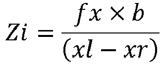
- In an embodiment of the present invention, the photographing apparatus is a depth camera incapable of directly obtaining Zi, and the determining the world coordinate of each feature point in the image relative to the photographing apparatus of the aircraft includes:
- obtaining pixel coordinates xr, yr and xl, yl of a same feature point in two adjacent images; and
- calculating Zi, Xi and Yi by using the following formula:


- In an embodiment of the present invention, the determining, according to the feature point, whether the landing area is the dangerous landing area includes:
- determining a plane that is fit to all the feature points;
- determining a ratio Ro of a quantity of a feature point that is not on the plane to a quantity of all the feature points;
- determining whether Ro is greater than a third preset threshold; and
- if yes, determining that the landing area is the dangerous landing area.
- In an embodiment of the present invention, the determining a ratio Ro of a quantity of the feature point that is not on the plane to a quantity of all the feature points includes:
- calculating a distance from each feature point to the plane by using the following formula:

- determining that a feature point having Di being greater than a fourth preset threshold is the feature point that is not on the plane; and
- calculating the ratio Ro of the quantity No of the feature point that is not on the plane to the quantity N of all the feature points:

- In an embodiment of the present invention, the determining, according to the feature point, whether the landing area is the dangerous landing area includes:
- determining a proportion Rd of a feature point whose movement distance is greater than a fifth preset threshold in two adjacent frames of images;
- determining whether Rd is greater than a sixth preset threshold; and
- if yes, determining that the landing area is the dangerous landing area.
- In an embodiment of the present invention, the determining the proportion Rd of the feature point whose movement distance is greater than a fifth preset threshold in two adjacent frames of images includes:
- determining a same feature point in the two adjacent frames of images;
- determining displacement coordinate xd, yd of each same feature point in the two adjacent frames of images;
- if xd or yd is greater than or equal to the fifth preset threshold, determining that the feature point is the feature point whose movement distance is greater than the fifth preset threshold; and
- calculating the proportion Rd of the feature point whose movement is greater than the fifth preset threshold to all the same feature points in the two sequential frames of images.
- In an embodiment of the present invention, the obtaining the image of the landing area includes:
obtaining the image of the landing area by using a photographing apparatus. - In an embodiment of the present invention, the photographing apparatus is a depth camera.
- In an embodiment of the present invention, the determining the feature point in the image includes:
determining the feature point in the image by using a corner detection method or a blob detection method. - In an embodiment of the present invention, the corner detection method includes at least one of the following:
a features from accelerated segment test (FAST) feature point detection method and a Harris corner detection method. - In an embodiment of the present invention, the determining the feature point in the image includes:
- obtaining a grayscale image of the image;
- randomly choosing one pixel p from the grayscale image, and choosing m pixels on a circle with the pixel p as the center of the circle and r pixels as the radius of the circle;
- calculating an absolute value of a difference between a grayscale value of the pixel p and a grayscale value of each of the m pixels;
- recording a quantity of the absolute value of the difference that is greater than a seventh preset threshold; and
- if the quantity of the absolute value of the difference that is greater than the seventh preset threshold is greater than an eighth preset threshold, determining that the pixel p is the feature point.
- In an embodiment of the present invention, the method further including:
if the landing area is the dangerous landing area, sending a prompt alarm. - An embodiment of the present invention further provides an aircraft landing protection apparatus, including:
- an obtaining module, configured to obtain an image of a landing area;
- a determining module, configured to determine a feature point in the image;
- a judging module, configured to determine, according to the feature point, whether the landing area is a dangerous landing area; and
- a control module, configured to control the aircraft to suspend landing or control the aircraft to fly away from the dangerous landing area.
- In an embodiment of the present invention, the judging module is configured to:
- determine whether a quantity of the feature point in the image is less than or equal to a first preset threshold;
- if yes, determine that the landing area is the dangerous landing area.
- In an embodiment of the present invention, the first preset threshold is 3.
- In an embodiment of the present invention, the judging module is configured to: determine a normal vector (nx, ny, nz) of a plane that is fit to all the feature points in the image;
determine whether nz in the normal vector (nx, ny, nz) is less than a second preset threshold; and
if yes, determine that the landing area is the dangerous landing area. - In an embodiment of the present invention, the judging module is configured to: determine a world coordinate of each feature point in the image relative to a photographing apparatus of the aircraft; and
calculate, by using the following formula, the normal vector (nx, ny, nz) of the plane that is fit to all the feature points in the image:
- where Xi, Yi, Zi is the world coordinate of an ith feature point relative to the photographing apparatus of the aircraft, i=1, ..., N, and N is the quantity of the feature point in the image.
- In an embodiment of the present invention, the photographing apparatus is a depth camera capable of directly obtaining Zi, and the judging module is configured to:
- obtain Zi in the world coordinate of each feature point by using the depth camera; and
- obtain a pixel coordinate xp, yp of each feature point, and calculate Xi, Yi by using the following formula:


- In an embodiment of the present invention, the photographing apparatus is a depth camera incapable of directly obtaining Zi, and the judging module is configured to:
- obtain pixel coordinates xr, yr and xl, yl of a same feature point in two adjacent images; and
- calculate Zi, Xi and Yi by using the following formula:


- In an embodiment of the present invention, the judging module is configured to:
- determine a plane that is fit to all the feature points;
- determine a ratio Ro of a quantity of a feature point that is not on the plane to a quantity of all the feature points;
- determine whether Ro is greater than a third preset threshold; and
- if yes, determine that the landing area is the dangerous landing area.
- In an embodiment of the present invention, the judging module is configured to:
- calculate a distance from each feature point to the plane by using the following formula:

- determine that a feature point having Di being greater than a fourth preset threshold is the feature point that is not on the plane; and
- calculate the ratio Ro of the quantity No of the feature point that is not on the plane to the quantity N of all the feature points:

- In an embodiment of the present invention, the judging module is configured to:
- determine a proportion Rd of a feature point whose movement distance is greater than a fifth preset threshold in two adjacent frames of images;
- determine whether Rd is greater than a sixth preset threshold; and
- if yes, determine that the landing area is the dangerous landing area.
- In an embodiment of the present invention, the judging module is configured to:
- determine a same feature point in the two adjacent frames of images;
- determine displacement coordinate xd, yd of each same feature point in the two adjacent frames of images;
- if xd or yd is greater than or equal to the fifth preset threshold, determine that the feature point is the feature point whose movement distance is greater than the fifth preset threshold; and
- calculate the proportion Rd of the feature point whose movement is greater than the fifth preset threshold to all the same feature points in the two sequential frames of images.
- In an embodiment of the present invention, the obtaining module is a photographing apparatus of the aircraft.
- In an embodiment of the present invention, the photographing apparatus is a depth camera.
- In an embodiment of the present invention, the determining module determines the feature point in the image by using a corner detection method or a blob detection method.
- In an embodiment of the present invention, the corner detection method includes at least one of the following:
a features from accelerated segment test (FAST)feature point detection method and a Harris corner detection method. - In an embodiment of the present invention, the determining module is configured to:
- obtain a grayscale image of the image;
- randomly choose one pixel p from the grayscale image, and choose m pixels on a circle with the pixel p as the center of the circle and r as the radius of the circle;
- calculate an absolute value of a difference between a grayscale value of the pixel p and a grayscale value of each of the m pixels;
- record a quantity of the absolute value of the difference that is greater than a seventh preset threshold; and
- if the quantity of the absolute value of the difference that is greater than the seventh preset threshold is greater than an eighth preset threshold, determine that the pixel p is the feature point.
- In an embodiment of the present invention, the apparatus further including:
a prompt alarm module, configured to: if the landing area is the dangerous landing area, send a prompt alarm. - An embodiment of the present invention further provides an aircraft, including:
- a housing;
- an arm connected to the housing;
- a processor disposed in the housing or the arm; and
- a memory that is connected to and communicates with the processor, the memory being disposed inside the housing or the arm, where
- the memory stores instructions executable by the processor, and when the processor executing the instruction, the processor implements the foregoing aircraft landing protection method.
- An embodiment of the present invention further provides a computer storage medium storing computer executable instructions, the computer executable instructions, when executed by an unmanned aerial vehicle, causing the unmanned aerial vehicle to perform the foregoing aircraft landing protection method.
- The present invention is capable of determining whether a landing area is a dangerous landing area according to an obtained image, so that ensures the landing safety of an aircraft.
- In an embodiment of the present invention, uneven ground, a slope, a foreign object in a descending area or a water surface can be reliably determined, thereby avoiding a crash during automatic landing.
- In an embodiment of the present invention, whether a current area is suitable for landing can be determined by using a depth camera alone, so that the device is simple with low computation complexity and high reliability.
-
-
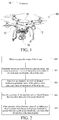
FIG. 1 is a schematic structural diagram of an aircraft according to an embodiment of the present invention; -
FIG. 2 is a flowchart of the aircraft shown inFIG. 1 determining a feature point in an image according to an embodiment of the present invention; -
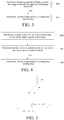
FIG. 3 is a flowchart of the aircraft shown inFIG. 1 determining whether a landing area is a dangerous landing area according to an embodiment of the present invention; -
FIG. 4 is a flowchart of the aircraft shown inFIG. 1 determining whether a landing area is a dangerous landing area according to another embodiment of the present invention; -
FIG. 5 is a diagram of a coordinate relationship among a feature point determined by the aircraft shown inFIG. 1 , a photographing apparatus of the aircraft, and a plane that is fit to feature points; -
FIG. 6 is a flowchart of the aircraft shown inFIG. 1 determining whether a landing area is a dangerous landing area; -
FIG. 7 is a flowchart of yet another embodiment of the aircraft shown inFIG. 1 determining whether a landing area is a dangerous landing area according to still another embodiment of the present invention; -
FIG. 8 is a flowchart of the aircraft shown inFIG. 1 determining a proportion Rd of a feature point whose movement distances is greater than a fifth preset threshold in two adjacent images; -
FIG. 9 is a flowchart of an aircraft landing protection method according to an embodiment of the present invention; and -
FIG. 10 is a structural block diagram of an aircraft landing protection apparatus according to an embodiment of the present invention. - Embodiments of the present invention are described below in detail with reference to the accompanying drawings.
- The steps illustrated in the flowcharts in the accompanying drawings can be carried out in a computer system with a group of computer executable instructions. Although the logical order of the steps is shown in the flowcharts, the illustrated or described steps may be carried out in a different order in some cases.
- The embodiments of the present invention provide an aircraft landing protection method and apparatus. The method and apparatus may be used for an aircraft, so as to automatically determine whether a landing area is suitable for landing during landing of the aircraft, thereby avoiding landing to a dangerous landing area. In the embodiments of the present invention, the dangerous landing area refers to any area that is not suitable for landing of the aircraft, such as ground with a relatively steep gradient (for example, a slope), a water surface, a bush and ground having a foreign object.
- The aircraft in the embodiments of the present invention may be an unmanned aircraft, a manned aircraft or the like.
- Referring to
FIG. 1 , anaircraft 10 in an embodiment of the present invention includes ahousing 11, anarm 12, apower apparatus 13, a photographingapparatus 14 and aprocessor 15. - The
arm 12 is connected to thehousing 11. Thepower apparatus 13 is disposed on thearm 12. The photographingapparatus 14 is connected to and communicates with theprocessor 15, and is configured to take an image of a landing area. - In an embodiment of the present invention, the photographing
apparatus 14 is a depth camera. The depth camera may include, but is not limited to a binocular camera, a time of flight (TOF) camera and a structured light camera. - The
aircraft 10 in this embodiment has fourarms 12. That is, theaircraft 10 in this embodiment is a quadcopter. In other possible embodiments, theaircraft 10 may further be a helicopter, a tricopter, a hexacopter, an octocopter, a fixed-wing aircraft, a mixed fixed-wing and rotary-wing aircraft or the like. - The
power apparatus 13 usually includes a motor disposed at an end of thearm 12 and a propeller connected to a shaft of the motor. The motor drives the propeller to rotate to provide a lifting force to theaircraft 10. Thepower apparatus 13 is connected to and communicates with theprocessor 15. - The
processor 15 may include a plurality of functional units, for example, a flight control unit configured to control a flight attitude of the aircraft, a target recognition unit configured to recognize a target, a tracking unit configured to track a specific target, a navigation unit (for example, a Global Positioning System (GPS) and BeiDou) configured to navigate the aircraft and a data processing unit configured to process environmental information obtained by a related onboard device. - When the
aircraft 10 is about to land, theaircraft 10 firstly obtains an image of a landing area by the photographingapparatus 14. - The landing area may be a landing position set by a user, or may be a landing point autonomously selected by the
aircraft 10, for example, a position where the aircraft needs to make an emergency landing when a battery power of the aircraft is low. - In an embodiment of the present invention, when a height of the
aircraft 10 from the landing area is less than or equal to a preset height, theaircraft 10 continuously obtains the image of the landing area by the photographingapparatus 14. - The preset height may be a height set by the user in advance, or may be a height set upon delivery of the
aircraft 10. For example, the preset height may be 5 meters. - After the image of the landing area is obtained, the
processor 15 needs to further determine a feature point in the image. - The feature point refers to a point whose image grayscale value changes sharply or a point with relatively large curvature at an edge of the image (that is, an intersection of two edges). The feature point can represent an intrinsic feature of the image, and can be used to identify a target object in the image. Image matching can be implemented through feature point matching.
- As shown in
FIG. 2 , in an embodiment of the present invention, theprocessor 15 may further determine the feature point in the image by using the following method: - S20: Obtain a grayscale image of the image.
- S21: Randomly choose one pixel p from the grayscale image, and choose m pixels on a circle with the pixel p as the center of the circle and r pixels as the radius of the circle.
- S22: Calculate an absolute value of a difference between a grayscale value of the pixel p and a grayscale value of each of the m pixels.
- S23: Record a quantity of the absolute value of the difference that is greater than a seventh preset threshold.
- S24: If the quantity of the absolute value of the difference that is greater than the seventh preset threshold is greater than an eighth preset threshold, determine that the pixel p is the feature point.
- In an embodiment of the present invention, the radius r=3, m=16, and the eighth preset threshold is usually 9. The seventh preset threshold may be chosen according to experience or an actual case.
- In an embodiment of the present invention, the
processor 15 may further determine the feature point in the image by using a corner detection method or a blob detection method. - The corner refers to a corner of an object or an intersection between lines in the image (a point with relatively large curvature at an edge of the image), and the blob usually refers to a point whose image grayscale value changes sharply.
- At present, there are multiple corner detection methods and blob detection methods. The corner detection method may include, but is not limited to a Features From Accelerated Segment Test (FAST)feature point detection method and a Harris corner detection method.
- In FAST feature point detection, a detected corner is defined as a pixel that has a sufficiently large quantity of pixels in neighboring areas around the pixel, where the large quantity of pixels and the pixel are located in different areas.
- The Harris corner detection method is a first-derivative matrix detection method based on image grayscale, in which detection is performed according to local self-similarity/self-correlation, that is, determining is performed according to the similarity between an image block in a local window and an image block in a window after a slight movement in each direction.
- The blob detection method may include, but is not limited to: a detection method using the Laplacian of the Gaussian (LOG)operator and a method using a Hessian matrix of a pixel and the value of a determinant of the Hessian matrix.
- It should be noted that at present there are many corner detection methods and blob detection methods, which are no longer described in the present invention, provided that a feature point can be detected. The present application is not limited to the several detection methods listed above.
- In an embodiment of the present invention, after the feature point in the image are determined, the
processor 15 may determine, according to the following method, whether the landing area is the dangerous landing area, and if the landing area is the dangerous landing area, controls theaircraft 10 to suspend landing or fly away from the dangerous landing area:
As shown inFIG. 3 , theprocessor 15 may determine, by using the following method, whether the landing area is the dangerous landing area: - S30: Determine whether a quantity of feature point in the image is less than or equal to a first preset threshold.
- S31: If yes, determine that the landing area is the dangerous landing area.
- Because the embodiment of the present invention needs to determine whether the landing area is the dangerous landing area according to information about multiple feature points, and therefore related determining cannot be performed when there are not enough feature points. In an embodiment of the present invention, the first preset threshold is 3. When the quantity of the feature point is less than 3, a plane cannot be fit to the feature point, and consequently a normal vector (nx, ny, nz) of the plane cannot be obtained. Therefore, when the quantity of feature point in the image is less than the first threshold, it is directly determined that the landing area is the dangerous landing area.
- As shown in
FIG. 4 , in other possible embodiments, theprocessor 15 may further determine, by using the following manner, whether the landing area is the dangerous landing area:
S41: Determine a normal vector (nx, ny, nz) of a plane that is fit to all the feature points in the image. - In an embodiment of the present invention, the normal vector (nx, ny, nz) of the plane that is fit to all the feature points may be obtained by using the following method:
- determining a world coordinate of each feature point in the image relative to the photographing apparatus of the aircraft; and
- calculating, by using the following formula, the normal vector (nx, ny, nz) of the plane that is fit to all the feature points in the image:

- In another embodiment of the present invention, the normal vector (nx, ny, nz) of the plane that is fit to all the feature points in the image is determined, or may further be obtained by using a random sample consensus (RANSAC) algorithm. In the algorithm, mathematical model parameters of data are calculated according to a group of sample data sets including anomaly data, so as to obtain effective sample data.
- Referring to
FIG. 5, FIG. 5 shows a coordinate relationship among a feature point (Xi, Yi, Zi), the photographingapparatus 14, and the plane. - In an embodiment of the present invention, the determining the world coordinate of each feature point in the image relative to the photographing apparatus may include the following two cases:
- (1) The photographing
apparatus 14 is a depth camera capable of directly obtaining Zi:
obtaining a pixel coordinate xp, yp of each feature point, and calculating Xi, Yi by using the following formula:

- (2) The photographing
apparatus 14 is a depth camera incapable of directly obtaining Zi, for example, a binocular camera that may indirectly obtain Zi:- obtaining pixel coordinates xr, yr and xl, yl of a same feature point in two adjacent images; and
- calculating Zi, Xi and Yi by using the following formula:


- S42: Determine whether nz in the normal vector (nx, ny, nz) is less than a second preset threshold.
- In an embodiment of the present invention, the second preset threshold is 0.9. When nz is less than 0.9, it indicates that the landing area has an excessively steep gradient and is not suitable for landing.
- S43: If yes, determine that the landing area is the dangerous landing area.
- As shown in
FIG. 6 , in another embodiment of the present invention, theprocessor 15 may further determine, by using the following method, whether the landing area is the dangerous landing area: - S61: Determine a plane that is fit to all the feature points. In an embodiment of the present invention, the plane may further be a horizontal plane.
- S62: Determine a ratio Ro of a quantity of the feature point that is not on the plane to a quantity of all the feature points.
- In an embodiment of the present invention, a distance from each feature point to the plane is first calculated by using the following formula:

- It is determined that a feature point having Di being greater than a fourth preset threshold is the feature point that is not on the plane. In an embodiment of the present invention, the fourth preset threshold may be 0.2s.
- The ratio Ro of the quantity No of the feature point that is not on the plane to the quantity N of all the feature points is calculated:

- S63: Determine whether Ro is greater than a third preset threshold.
- When Ro is greater than the third preset threshold, it indicates that the landing area is uneven, may have a foreign object and is not suitable for landing. In an embodiment of the present invention, the third threshold may be set to 0.01.
- S64: If yes, determine that the landing area is the dangerous landing area.
- As shown in
FIG. 7 , in another embodiment of the present invention, theprocessor 15 may further determine, by using the following method, whether the landing area is the dangerous landing area: - S70: Determine a proportion Rd of a feature point whose movement distance is greater than a fifth preset threshold in two adjacent frames of images.
As shown inFIG. 8 , in an embodiment of the present invention, theprocessor 15 may determine, according to the following method, the proportion Rd of the feature point whose movement distance is greater than the fifth preset threshold in two adjacent frames of images: - S701: Determine a same feature point in the two adjacent frames of images.
- S702: Determine displacement coordinate xd, yd of each same feature point in the two adjacent frames of images.
- S703: If xd or yd is greater than or equal to the fifth preset threshold, determine that the feature point is the feature point whose movement distance is greater than the fifth preset threshold.
In another embodiment of the present invention, same feature points in two sequential frames of images may be determined by using a feature point matching manner, that is, whether two feature points are the same feature point is determined according to a degree of similarity between the two feature points. Similar to feature point detection, there are also many algorithms of feature point matching, which are no longer described in the present invention. - S704: Calculate the proportion Rd of the feature point whose movement is greater than the fifth preset threshold to all the same feature points in the two sequential frames of images.
In an embodiment of the present invention, the fifth preset threshold is two pixels. - S71: Determine whether Rd is greater than a sixth preset threshold.
When Rd is greater than the sixth preset threshold, it indicates that the landing area may be a water surface or another dangerous area, and is not suitable for landing of the aircraft. In an embodiment of the present invention, the sixth preset threshold is 0.1. - S72: If yes, determine that the landing area is the dangerous landing area.
- In an embodiment of the present invention, after the
processor 15 determines that the landing area is the dangerous landing area, theaircraft 10 may further perform at least one of the following: - sending a prompt alarm to a control terminal; and
- changing the landing area according to a preset rule.
- The
processor 15 may send a prompt alarm to the control terminal. The control terminal receives a control instruction input by a user, and changes the landing area according to the control instruction. It is then determined whether the changed landing area is the dangerous landing area. - The
processor 15 may further directly change the landing area according to a preset rule. The preset rule may be to control theaircraft 10 to fly a specific distance in a preset direction, and then use the location below the current position as the landing area. - In an embodiment of the present invention, after the
processor 15 determines that the landing area is the dangerous landing area, the position of the dangerous landing area may further be recorded, and a landing strategy is provided to theaircraft 10 according to the recorded position of the dangerous landing area. The position may include geographical coordinates. - In an embodiment of the present invention, the
processor 15 may send the position of the dangerous landing area to the control terminal, and the control terminal displays information about the position, so as to inform the user of the geographical position and prevent the user from setting the position as the landing area again. In addition, during subsequent flight, if the landing area is said position, theprocessor 15 may directly determine the position as the dangerous landing area. - In this embodiment of the present invention, whether a landing area is the dangerous landing area may be determined according to the obtained image, so that the landing safety of the aircraft is ensured. Moreover, by means of this embodiment of the present invention, uneven ground, a slope, a foreign object in a descending area or a water surface can be reliably determined, thereby avoiding a crash during automatic landing in the foregoing area. In addition, in this embodiment of the present invention, whether a current area is suitable for landing can be determined by using the depth camera alone, so that the device is simple with low computation complexity and high reliability.
- As shown in
FIG. 9 , an embodiment of the present invention further provides an aircraft landing protection method, the method including:
S90: Obtain an image of a landing area. - In an embodiment of the present invention, a photographing apparatus of the aircraft may be used to obtain the image of the landing area. The photographing apparatus may be a depth camera, for example, a binocular camera, a TOF camera and a structured light camera.
- The landing area may be a landing position set by a user, or may be a landing point autonomously selected by the
aircraft 10, for example, a position where the aircraft needs to make an emergency landing when a battery power of the aircraft is low. - In an embodiment of the present invention, when a height of the
aircraft 10 from the landing area is less than or equal to a preset height, the photographingapparatus 14 is used to continuously obtain the image of the landing area. - The preset height may be a height set by the user in advance, or may be a height set upon delivery of the
aircraft 10. For example, the preset height may be 5 meters. - S91: Determine a feature point in the image.
- As shown in
FIG. 2 , in an embodiment of the present invention, the aircraft may determine the feature point in the image by using the following method: - S20: Obtain a grayscale image of the image.
- S21: Randomly choose one pixel p from the grayscale image, and choose m pixels from a circle with the pixel p as the center of the circle and r pixels as the radius of the circle.
- S22: Calculate an absolute value of a difference between a grayscale value of the pixel p and a grayscale value of each of the m pixels.
- S23. Record a quantity of the absolute value of the difference that is greater than a seventh preset threshold.
- S24: If the quantity of the absolute value of the difference that is greater than the seventh preset threshold is greater than an eighth preset threshold, determine that the pixel p is the feature point.
- In an embodiment of the present invention, the radius r=3, m=16, and the eighth preset threshold is usually 9. The seventh preset threshold may be chosen according to experience or an actual case.
- In another embodiment of the present invention, the feature point in the image may further be determined by using a corner detection method or a blob detection method.
- S92: Determine, according to the feature point, whether the landing area is the dangerous landing area.
- As shown in
FIG. 3 , the aircraft may determine, by using the following method, whether the landing area is the dangerous landing area: - S30: Determine whether a quantity of feature point in the image is less than or equal to a first preset threshold.
- S31: If yes, determine that the landing area is the dangerous landing area.
- In this embodiment of the present invention, information about multiple feature points is needed to determine whether the landing area is the dangerous landing area, and therefore related determining cannot be performed when there are not enough feature points. In an embodiment of the present invention, the first preset threshold is 3. When the quantity of the feature point is less than 3, a plane cannot be fit to the feature point, and consequently a normal vector (nx, ny, nz) of the plane cannot be obtained. Therefore, when the quantity of feature point in the image is less than the first threshold, it is directly determined that the landing area is the dangerous landing area.
- As shown in
FIG. 4 , in other possible embodiments, the aircraft may further determine, by using the following manner, whether the landing area is the dangerous landing area:
S41: Determine a normal vector (nx, ny, nz) of a plane that is fit to all the feature points in the image. - In an embodiment of the present invention, the normal vector (nx, ny, nz) of the plane that is fit to all the feature points may be obtained by using the following method:
- determining a world coordinate of each feature point in the image relative to a photographing apparatus of the aircraft; and
- calculating, by using the following formula, the normal vector (nx, ny, nz) of the plane that is fit to all the feature points in the image:

- In another embodiment of the present invention, the normal vector (nx, ny, nz) of the plane that is fit to all the feature points in the image is determined, or may further be obtained by using a RANSAC algorithm. In the algorithm, mathematical model parameters of data are calculated according to a group of sample data sets including anomaly data, so as to obtain effective sample data.
- Referring to
FIG. 5, FIG. 5 shows a coordinate relationship among the feature point (Xi, Yi, Zi), the photographingapparatus 14, and the plane. - In an embodiment of the present invention, the determining the world coordinate of each feature point in the image relative to the photographing apparatus may include the following two cases:
- (1) The photographing apparatus is a depth camera capable of directly obtaining the value of Zi:
obtaining pixel coordinates xp, yp of each feature point, and calculating Xi, Yi by using the following formula:

- (2) The photographing apparatus is incapable of directly obtaining the value of Zi, and is, for example, a binocular camera that may indirectly obtain Zi:
- obtaining pixel coordinates xr, yr and xl, yl of a same feature point in two adjacent images; and
- calculating Zi, Xi and Yi by using the following formula:


- S42: Determine whether nz in the normal vector (nx, ny, nz) is less than a second preset threshold.
- In an embodiment of the present invention, the second preset threshold is 0.9. When nz is less than 0.9, it indicates that the landing area has an excessively steep gradient and is not suitable for landing.
- S43: If yes, determine that the landing area is the dangerous landing area.
- As shown in
FIG. 6 , in another embodiment of the present invention, the aircraft may further determine, by using the following method, whether the landing area is the dangerous landing area: - S61: Determine a plane that is fit to all the feature points. In an embodiment of the present invention, the plane may further be a horizontal plane.
- 562: Determine a ratio Ro of a quantity of the feature point that is not on the plane to a quantity of all the feature points.
- In an embodiment of the present invention, a distance from each feature point to the plane is first calculated by using the following formula:

- It is determined that a feature point having Di being greater than a fourth preset threshold is the feature points that is not on the plane. In an embodiment of the present invention, the fourth preset threshold may be 0.2m.
- The ratio Ro of the quantity No of the feature point that is not on the plane to the quantity N of all the feature points is calculated:

- S63: Determine whether Ro is greater than a third preset threshold.
- When Ro is greater than the third preset threshold, it indicates that the landing area is uneven, may have a foreign object, and is not suitable for landing. In an embodiment of the present invention, the third threshold may be set to 0.01.
- S64: If yes, determine that the landing area is a dangerous landing area.
- As shown in
FIG. 7 , in another embodiment of the present invention, the aircraft may further determine, by using the following method, whether the landing area is the dangerous landing area:
S70: Determine a proportion Rd of a feature point whose movement distance is greater than a fifth preset threshold in two adjacent frames of images. - As shown in
FIG. 8 , in an embodiment of the present invention, the aircraft may determine, according to the following method, the proportion Rd of the feature point whose movement distance is greater than the fifth preset threshold in two adjacent frames of images: - S701: Determine a same feature point in the two adjacent frames of images.
- S702: Determine displacement coordinate xd, yd of each same feature point in the two adjacent frames of images.
- S703: If xd or yd is greater than or equal to the fifth preset threshold, determine that the feature point is the feature point whose movement distance is greater than the fifth preset threshold.
In another embodiment of the present invention, the same feature point in two sequential frames of images may be determined by using a feature point matching manner, that is, whether two feature points are the same feature point is determined according to a degree of similarity between the two feature points. Similar to feature point detection, there are also many algorithms of feature point matching, which are no longer described in the present invention. - S704: Calculate the proportion Rd of the feature point whose movement is greater than the fifth preset threshold to all the same feature points in the two sequential frames of images.
In an embodiment of the present invention, the fifth preset threshold is two pixels. - S71: Determine whether Rd is greater than a sixth preset threshold.
When Rd is greater than the sixth preset threshold, it indicates that the landing area may be a water surface or another dangerous area, and is not suitable for landing of the aircraft. In an embodiment of the present invention, the sixth preset threshold is 0.1. - S72: If yes, determine that the landing area is the dangerous landing area.
- S93: If yes, the aircraft suspends landing or the aircraft flies away from the dangerous landing area.
- In an embodiment of the present invention, after it is determined that the landing area is the dangerous landing area, the
aircraft 10 may further perform at least one of the following: - sending a prompt alarm to a control terminal; and
- changing the landing area according to a preset rule.
- The aircraft may send the prompt alarm to the control terminal. The control terminal receives a control instruction input by a user, and changes the landing area according to the control instruction. It is then determined whether the changed landing area is the dangerous landing area.
- The aircraft may further directly change the landing area according to a preset rule. The preset rule may be to control the aircraft to fly a specific distance in a preset direction, and then use the location below the current position as a landing area.
- In an embodiment of the present invention, after it is determined that the landing area is the dangerous landing area, the position of the dangerous landing area may further be recorded, and the aircraft autonomously selects a landing strategy according to the recorded position of the dangerous landing area. The position may include geographical coordinates.
- In an embodiment of the present invention, the position of the dangerous landing area may be sent to the control terminal, and the control terminal displays information about the position, so as to inform the user of the geographical position and prevent the user from setting the position as the landing area again. In addition, during subsequent flight, if the landing area is the position, the position may be directly determined as the dangerous landing area.
- Reference may be made to the foregoing description for the detailed content relating to the steps in the method, and details are no longer described here.
- An embodiment of the present invention further provides an aircraft landing protection apparatus. The apparatus is configured to implement the foregoing embodiments and implementations, and the described content is no longer described. For example, the term "module" used in the following may be a combination of software and/or hardware that implements a predetermined function. Although the apparatus described in the following embodiment may be implemented by using software, the implementation of hardware or a combination of software and hardware is also possible and conceivable.
- As shown in
FIG. 10 , an embodiment of the present invention further provides an aircraftlanding protection apparatus 100. The apparatus includes: - an obtaining
module 101, configured to obtain an image of a landing area; - a determining
module 102, configured to determine a feature point in the image; - a judging
module 103, configured to determine, according to the feature point, whether the landing area is a dangerous landing area; and - a
control module 104, configured to control the aircraft to suspend landing or control the aircraft to fly away from the dangerous landing area. - In an embodiment of the present invention, the judging
module 103 is configured to: - determine whether a quantity of the feature point in the image is less than or equal to a first preset threshold; and
- if yes, determine that the landing area is the dangerous landing area.
- In an embodiment of the present invention, the first preset threshold is 3.
- In an embodiment of the present invention, the judging module is configured to:
- determine a normal vector (nx, ny, nz) of a plane that is fit to all the feature points in the image;
- determine whether nz in the normal vector (nx, ny, nz) is less than a second preset threshold; and
- if yes, determine that the landing area is the dangerous landing area.
- In an embodiment of the present invention, the judging
module 103 is configured to: - determine a world coordinate of each feature point in the image relative to a photographing apparatus of the aircraft; and
- calculate, by using the following formula, the normal vector (nx, ny, nz) of the plane that is fit to all the feature points in the image:

- In an embodiment of the present invention, the photographing apparatus is a depth camera, and the judging
module 103 is configured to: - obtain Zi in the world coordinate of each feature point by using the depth camera; and
- obtain a pixel coordinate xp, yp of each feature point, and calculate Xi, Yi by using the following formula:


- In an embodiment of the present invention, the photographing apparatus is a binocular camera, and the judging
module 103 is configured to: - obtain pixel coordinates xr, yr and xl, yl of a same feature point in two adjacent images; and
- calculate Zi, Xi and Yi by using the following formula:


- In an embodiment of the present invention, the judging
module 103 is configured to: - determine a plane that is fit to all the feature points;
- determine a ratio Ro of a quantity of a feature point that is not on the plane to a quantity of all the feature points;
- determine whether Ro is greater than a third preset threshold; and
- if yes, determine that the landing area is the dangerous landing area.
- In an embodiment of the present invention, the judging
module 103 is configured to: - calculate a distance from each feature point to the plane by using the following formula:

- determine that a feature point having Di being greater than a fourth preset threshold is the feature point that is not on the plane; and
- calculate the ratio Ro of the quantity No of the feature point that is not on the plane to the quantity N of all the feature points:

- In an embodiment of the present invention, the judging
module 103 is configured to: - determine a proportion Rd of a feature point whose movement distance is greater than a fifth preset threshold in two adjacent frames of images;
- determine whether Rd is greater than a sixth preset threshold; and
- if yes, determine that the landing area is the dangerous landing area.
- In an embodiment of the present invention, the judging
module 103 is configured to: - determine a same feature points in the two adjacent frames of images;
- determine displacement coordinate xd, yd of each same feature point in the two adjacent frames of images;
- if xd or yd is greater than or equal to the fifth preset threshold, determine that the feature point is the feature point whose movement distance is greater than the fifth preset threshold; and
- calculate the proportion Rd of the feature point whose movement is greater than the fifth preset threshold to all the same feature points in the two sequential frames of images.
- In an embodiment of the present invention, the obtaining
module 101 is a photographing apparatus of the aircraft. - In an embodiment of the present invention, the photographing apparatus is a depth camera.
- In an embodiment of the present invention, the determining
module 102 determines the feature point in the image by using a corner detection method or a blob detection method. - In an embodiment of the present invention, the corner detection method includes at least one of the following:
a FAST feature point detection method and a Harris corner detection method. - In an embodiment of the present invention, the determining
module 102 is configured to: - obtain a grayscale image of the image;
- randomly choose one pixel p from the grayscale image, and choose m pixels on a circle with the pixel p as the center of the circle and r as the radius of the circle;
- calculate an absolute value of a difference between a grayscale value of the pixel p and a grayscale value of each of the m pixels;
- record a quantity of the absolute value of the difference that is greater than a seventh preset threshold; and
- if the quantity of the absolute value of the difference that is greater than the seventh preset threshold is greater than an eighth preset threshold, determine that the pixel p is the feature point.
- In an embodiment of the present invention, the apparatus further includes:
aprompt alarm module 105, configured to: if the landing area is the dangerous landing area, send a prompt alarm. - Reference may be made to the foregoing description for the detailed content relating to the modules in the apparatus, and details are no longer described here.
- An embodiment of the present invention further provides an aircraft, including a processor and a computer readable storage medium. The computer readable storage medium stores instructions. When the processor executing the instruction, the processor implements any of the foregoing aircraft landing protection methods.
- An embodiment of the present invention further provides a computer readable storage medium. The computer readable storage medium stores a computer program. When executing the computer program, the processor implements any of the foregoing aircraft landing protection methods.
- The computer readable storage medium may include, but is not limited to: any medium that can store program code, such as a USB flash drive, a read-only memory (ROM), a random-access memory (RAM), a removable hard disk, a magnetic disk or an optical disc.
- Apparently, persons skilled in the art should understand that the foregoing modules or steps in the embodiments of the present invention may be implemented by using a common computing apparatus. The modules or steps may be arranged in a single computing apparatus or distributed in a network formed of multiple computing apparatuses. Optionally, the modules or steps may be implemented by using program code executable by a computing apparatus, so that the modules or steps may be stored in a storage apparatus and executed by the computing apparatus, and in some cases, the shown or described steps may be performed in orders different from those here, the steps are separately manufactured into integrated circuit modules for implementation, or some of the modules or steps are manufactured into a single integrated circuit module for implementation. In this way, the embodiments of the present invention are not limited to any specific combination of hardware and software.
- Although the implementations of the present application are disclosed above, the content is only used for ease of understanding of implementations used in the present application, but is not used to limit the present application. Any person skilled in the field of the present application may make any modification or variation to implementation forms and details without departing from the spirit and scope of the present application, but the protection scope of the patent of the present application should still be as defined by the appended claims.


Claims (36)
- An aircraft landing protection method, comprising:obtaining an image of a landing area;determining a feature point in the image;determining, according to the feature point, whether the landing area is a dangerous landing area; andif yes, controlling the aircraft to suspend landing or controlling the aircraft to fly away from the dangerous landing area.
- The method according to claim 1, wherein the determining, according to the feature point, whether the landing area is the dangerous landing area comprises:determining whether a quantity of the feature point in the image is less than or equal to a first preset threshold; andif yes, determining that the landing area is the dangerous landing area.
- The method according to claim 2, wherein the first preset threshold is 3.
- The method according to claim 1, wherein the determining, according to the feature point, whether the landing area is the dangerous landing area comprises:determining a normal vector (nx, ny, nz) of a plane that is fit to all the feature points in the image;determining whether nz in the normal vector (nx, ny, nz) is less than a second preset threshold; andif yes, determining that the landing area is the dangerous landing area.
- The method according to claim 4, wherein the determining the normal vector (nx, ny, nz) of the plane that is fit to all the feature points in the image comprises:determining a world coordinate of each feature point in the image relative to a photographing apparatus of the aircraft; andcalculating, by using the following formula, the normal vector (nx, ny, nz) of the plane that is fit to all the feature points in the image:

- The method according to claim 5, wherein the photographing apparatus is a depth camera capable of directly obtaining Zi, and the determining the world coordinate of each feature point in the image relative to the photographing apparatus of the aircraft comprises:obtaining Zi in the world coordinate of each feature point by using the depth camera; andobtaining a pixel coordinate xp, yp of each feature point, and calculating Xi, Yi by using the following formula:


- The method according to claim 5, wherein the photographing apparatus is a depth camera incapable of directly obtaining Zi, and the determining the world coordinate of each feature point in the image relative to the photographing apparatus of the aircraft comprises:obtaining pixel coordinates xr, yr and xl, yl of a same feature point in two adjacent images; andcalculating Zi, Xi and Yi by using the following formula:


- The method according to claim 1, wherein the determining, according to the feature point, whether the landing area is the dangerous landing area comprises:determining a plane that is fit to all the feature points;determining a ratio Ro of a quantity of a feature point that is not on the plane to a quantity of all the feature points;determining whether Ro is greater than a third preset threshold; andif yes, determining that the landing area is the dangerous landing area.
- The method according to claim 8, wherein the determining a ratio Ro of a quantity of the feature point that is not on the plane to a quantity of all the feature points comprises:calculating a distance from each feature point to the plane by using the following formula:
 determining that a feature point having Di being greater than a fourth preset threshold is the feature point that is not on the plane; andcalculating the ratio Ro of the quantity No of the feature point that is not on the plane to the quantity N of all the feature points:
- The method according to claim 1, wherein the determining, according to the feature point, whether the landing area is the dangerous landing area comprises:determining a proportion Rd of a feature point whose movement distance is greater than a fifth preset threshold in two adjacent frames of images;determining whether Rd is greater than a sixth preset threshold; andif yes, determining that the landing area is the dangerous landing area.
- The method according to claim 10, wherein the determining the proportion Rd of the feature point whose movement distance is greater than a fifth preset threshold in two adjacent frames of images comprises:determining a same feature point in the two adjacent frames of images;determining displacement coordinate xd, yd of each same feature point in the two adjacent frames of images;if xd or yd is greater than or equal to the fifth preset threshold, determining that the feature point is the feature point whose movement distance is greater than the fifth preset threshold; andcalculating the proportion Rd of the feature point whose movement is greater than the fifth preset threshold to all the same feature points in the two sequential frames of images.
- The method according to any of claims 1 to 11, wherein the obtaining the image of the landing area comprises:
obtaining the image of the landing area by using a photographing apparatus. - The method according to claim 12, wherein the photographing apparatus is a depth camera.
- The method according to any of claims 1 to 13, wherein the determining the feature point in the image comprises:
determining the feature point in the image by using a corner detection method or a blob detection method. - The method according to claim 14, wherein the corner detection method comprises at least one of the following:
a features from accelerated segment test (FAST) feature point detection method and a Harris corner detection method. - The method according to any of claims 1 to 13, wherein the determining the feature point in the image comprises:obtaining a grayscale image of the image;randomly choosing one pixel p from the grayscale image, and choosing m pixels on a circle with the pixel p as the center of the circle and r pixels as the radius of the circle;calculating an absolute value of a difference between a grayscale value of the pixel p and a grayscale value of each of the m pixels;recording a quantity of the absolute value of the difference that is greater than a seventh preset threshold; andif the quantity of the absolute value of the difference that is greater than the seventh preset threshold is greater than an eighth preset threshold, determining that the pixel p is the feature point.
- The method according to any of claims 1 to 16, further comprising:
if the landing area is the dangerous landing area, sending a prompt alarm. - An aircraft landing protection apparatus, comprising:an obtaining module, configured to obtain an image of a landing area;a determining module, configured to determine a feature point in the image;a judging module, configured to determine, according to the feature point, whether the landing area is a dangerous landing area; anda control module, configured to control the aircraft to suspend landing or control the aircraft to fly away from the dangerous landing area.
- The apparatus according to claim 18, wherein the judging module is configured to:determine whether a quantity of the feature point in the image is less than or equal to a first preset threshold;if yes, determine that the landing area is the dangerous landing area.
- The apparatus according to claim 19, wherein the first preset threshold is 3.
- The apparatus according to claim 18, wherein the judging module is configured to:
determine a normal vector (nx, ny, nz) of a plane that is fit to all the feature points in the image;determine whether nz in the normal vector (nx, ny, nz) is less than a second preset threshold; andif yes, determine that the landing area is the dangerous landing area. - The apparatus according to claim 21, wherein the judging module is configured to:determine a world coordinate of each feature point in the image relative to a photographing apparatus of the aircraft; andcalculate, by using the following formula, the normal vector (nx, ny, nz) of the plane that is fit to all the feature points in the image:

- The apparatus according to claim 22, wherein the photographing apparatus is a depth camera capable of directly obtaining Zi, and the judging module is configured to:obtain Zi in the world coordinate of each feature point by using the depth camera; andobtain a pixel coordinate xp, yp of each feature point, and calculate Xi, Yi by using the following formula:


- The apparatus according to claim 22, wherein the photographing apparatus is a depth camera incapable of directly obtaining Zi, and the judging module is configured to:obtain pixel coordinates xr, yr and xl, yl of a same feature point in two adjacent images; andcalculate Zi, Xi and Yi by using the following formula:


- The apparatus according to claim 18, wherein the judging module is configured to:determine a plane that is fit to all the feature points;determine a ratio Ro of a quantity of a feature point that is not on the plane to a quantity of all the feature points;determine whether Ro is greater than a third preset threshold; andif yes, determine that the landing area is the dangerous landing area.
- The apparatus according to claim 25, wherein the judging module is configured to:calculate a distance from each feature point to the plane by using the following formula:
 determine that a feature point having Di being greater than a fourth preset threshold is the feature point that is not on the plane; andcalculate the ratio Ro of the quantity No of the feature point that is not on the plane to the quantity N of all the feature points:
- The apparatus according to claim 18, wherein the judging module is configured to:determine a proportion Rd of a feature point whose movement distance is greater than a fifth preset threshold in two adjacent frames of images;determine whether Rd is greater than a sixth preset threshold; andif yes, determine that the landing area is the dangerous landing area.
- The apparatus according to claim 27, wherein the judging module is configured to:determine a same feature point in the two adjacent frames of images;determine displacement coordinate xd, yd of each same feature point in the two adjacent frames of images;if xd or yd is greater than or equal to the fifth preset threshold, determine that the feature point is the feature point whose movement distance is greater than the fifth preset threshold; andcalculate the proportion Rd of the feature point whose movement is greater than the fifth preset threshold to all the same feature points in the two sequential frames of images.
- The apparatus according to any of claims 18 to 28, wherein the obtaining module is a photographing apparatus of the aircraft.
- The apparatus according to claim 29, wherein the photographing apparatus is a depth camera.
- The apparatus according to any of claims 18 to 30, wherein the determining module determines the feature point in the image by using a corner detection method or a blob detection method.
- The apparatus according to claim 31, wherein the corner detection method comprises at least one of the following:
a features from accelerated segment test (FAST)feature point detection method and a Harris corner detection method. - The apparatus according to any of claims 18 to 30, wherein the determining module is configured to:obtain a grayscale image of the image;randomly choose one pixel p from the grayscale image, and choose m pixels on a circle with the pixel p as the center of the circle and r as the radius of the circle;calculate an absolute value of a difference between a grayscale value of the pixel p and a grayscale value of each of the m pixels;record a quantity of the absolute value of the difference that is greater than a seventh preset threshold; andif the quantity of the absolute value of the difference that is greater than the seventh preset threshold is greater than an eighth preset threshold, determine that the pixel p is the feature point.
- The apparatus according to any of claims 18 to 33, further comprising:
a prompt alarm module, configured to: if the landing area is the dangerous landing area, send a prompt alarm. - An aircraft, comprising:a housing;an arm connected to the housing;a processor disposed in the housing or the arm; anda memory that is connected to and communicates with the processor, the memory being disposed inside the housing or the arm, whereinthe memory stores instructions executable by the processor, and when the processor executing the instruction, the processor implements the method according to any of claims 1 to 17.
- A computer storage medium storing computer executable instructions, the computer executable instructions, when executed by an unmanned aerial vehicle, causing the unmanned aerial vehicle to perform the method according to any of claims 1 to 17.
Applications Claiming Priority (1)
| Application Number | Priority Date | Filing Date | Title |
|---|---|---|---|
| PCT/CN2017/118662 WO2019127023A1 (en) | 2017-12-26 | 2017-12-26 | Protective aircraft landing method and device and aircraft |
Publications (3)
| Publication Number | Publication Date |
|---|---|
| EP3528081A1 true EP3528081A1 (en) | 2019-08-21 |
| EP3528081A4 EP3528081A4 (en) | 2019-11-13 |
| EP3528081B1 EP3528081B1 (en) | 2026-03-25 |
Family
ID=66950406
Family Applications (1)
| Application Number | Title | Priority Date | Filing Date |
|---|---|---|---|
| EP17842281.2A Active EP3528081B1 (en) | 2017-12-26 | 2017-12-26 | Protective aircraft landing method and device and aircraft |
Country Status (4)
| Country | Link |
|---|---|
| US (1) | US10796148B2 (en) |
| EP (1) | EP3528081B1 (en) |
| CN (1) | CN110402421A (en) |
| WO (1) | WO2019127023A1 (en) |
Families Citing this family (6)
| Publication number | Priority date | Publication date | Assignee | Title |
|---|---|---|---|---|
| CN114476105B (en) * | 2016-08-06 | 2025-01-03 | 深圳市大疆创新科技有限公司 | Automatic landing surface terrain assessment and related systems and methods |
| US10866593B2 (en) * | 2017-09-20 | 2020-12-15 | Autel Robotics Co., Ltd. | Aerial vehicle landing method, ground control system, and flight control system |
| US11036240B1 (en) * | 2018-06-18 | 2021-06-15 | Amazon Technologies, Inc. | Safe landing of aerial vehicles upon loss of navigation |
| US11808578B2 (en) * | 2020-05-29 | 2023-11-07 | Aurora Flight Sciences Corporation | Global positioning denied navigation |
| CA3183510A1 (en) * | 2020-07-01 | 2022-01-06 | Mdgroup Germany Gmbh | Method and system for controlling aircraft |
| CN115496930B (en) * | 2022-11-08 | 2023-03-21 | 之江实验室 | Image processing method and device, storage medium and electronic equipment |
Family Cites Families (23)
| Publication number | Priority date | Publication date | Assignee | Title |
|---|---|---|---|---|
| RU2460187C2 (en) * | 2008-02-01 | 2012-08-27 | Рокстек Аб | Transition frame with inbuilt pressing device |
| JP6110316B2 (en) * | 2011-02-21 | 2017-04-05 | ストラテック システムズ リミテッドStratech Systems Limited | Surveillance system and method for detecting foreign objects, debris, or damage in an airfield |
| JP5882693B2 (en) * | 2011-11-24 | 2016-03-09 | 株式会社トプコン | Aerial photography imaging method and aerial photography imaging apparatus |
| GB201118694D0 (en) * | 2011-10-28 | 2011-12-14 | Bae Systems Plc | Identification and analysis of aircraft landing sites |
| US8744126B1 (en) * | 2012-03-07 | 2014-06-03 | Ball Aerospace & Technologies Corp. | Morphology based hazard detection |
| CN102929284B (en) * | 2012-10-26 | 2016-03-09 | 哈尔滨工程大学 | A kind of aircraft isolated island landing is gone around decision-making technique |
| EP2986940A4 (en) * | 2013-04-16 | 2017-04-05 | Bae Systems Australia Limited | Landing site tracker |
| US20160093225A1 (en) * | 2013-04-16 | 2016-03-31 | Bae Systems Australia Limited | Landing system for an aircraft |
| CN104058095B (en) * | 2014-06-12 | 2016-06-29 | 深圳市哈博森科技有限公司 | Aircraft parachute controls system and method |
| CN110989668B (en) * | 2014-12-15 | 2024-11-08 | 深圳市大疆创新科技有限公司 | Aircraft and its take-off control method and system, landing control method and system |
| US9429953B1 (en) * | 2015-08-25 | 2016-08-30 | Skycatch, Inc. | Autonomously landing an unmanned aerial vehicle |
| JP6680498B2 (en) * | 2015-09-28 | 2020-04-15 | 株式会社日立システムズ | Autonomous flying vehicle, target tracking method |
| CN105259917A (en) * | 2015-11-08 | 2016-01-20 | 杨珊珊 | Quick and safe landing device and method for unmanned aerial vehicle |
| EP3391647B1 (en) * | 2015-12-18 | 2023-11-01 | BOE Technology Group Co., Ltd. | Method, apparatus, and non-transitory computer readable medium for generating depth maps |
| CN105787192B (en) * | 2016-03-15 | 2020-06-23 | 联想(北京)有限公司 | Information processing method and aircraft |
| CN107310716A (en) * | 2016-04-26 | 2017-11-03 | 零度智控(北京)智能科技有限公司 | Control system and method that aircraft lands automatically |
| CN106326892B (en) * | 2016-08-01 | 2020-06-09 | 西南科技大学 | A visual landing pose estimation method for rotary-wing UAV |
| CN106494632B (en) * | 2016-09-05 | 2019-11-29 | 珠海市磐石电子科技有限公司 | The mobile landing system of aircraft and mobile landing method |
| CN109690433B (en) * | 2016-09-13 | 2022-05-17 | 杭州零零科技有限公司 | Unmanned aerial vehicle system and method with environmental awareness |
| US10152059B2 (en) * | 2016-10-10 | 2018-12-11 | Qualcomm Incorporated | Systems and methods for landing a drone on a moving base |
| CN106504321A (en) * | 2016-11-07 | 2017-03-15 | 达理 | Method using the method for photo or video reconstruction three-dimensional tooth mould and using RGBD image reconstructions three-dimensional tooth mould |
| CN106444797A (en) * | 2016-12-01 | 2017-02-22 | 腾讯科技(深圳)有限公司 | Method for controlling aircraft to descend and related device |
| US10402646B2 (en) * | 2017-09-21 | 2019-09-03 | Amazon Technologies, Inc. | Object detection and avoidance for aerial vehicles |
-
2017
- 2017-12-26 CN CN201780002740.0A patent/CN110402421A/en active Pending
- 2017-12-26 WO PCT/CN2017/118662 patent/WO2019127023A1/en not_active Ceased
- 2017-12-26 EP EP17842281.2A patent/EP3528081B1/en active Active
-
2018
- 2018-02-12 US US15/894,126 patent/US10796148B2/en active Active
Also Published As
| Publication number | Publication date |
|---|---|
| US10796148B2 (en) | 2020-10-06 |
| CN110402421A (en) | 2019-11-01 |
| EP3528081B1 (en) | 2026-03-25 |
| EP3528081A4 (en) | 2019-11-13 |
| WO2019127023A1 (en) | 2019-07-04 |
| US20190197291A1 (en) | 2019-06-27 |
Similar Documents
| Publication | Publication Date | Title |
|---|---|---|
| EP3528081B1 (en) | Protective aircraft landing method and device and aircraft | |
| EP3903164B1 (en) | Collision avoidance system, depth imaging system, vehicle, map generator, amd methods thereof | |
| JP7252943B2 (en) | Object detection and avoidance for aircraft | |
| EP3497672B1 (en) | Pallet localization systems and methods | |
| CN111615677B (en) | Unmanned aerial vehicle safety landing method and device, unmanned aerial vehicle and medium | |
| US10778967B2 (en) | Systems and methods for improving performance of a robotic vehicle by managing on-board camera defects | |
| US8744126B1 (en) | Morphology based hazard detection | |
| CN114476105B (en) | Automatic landing surface terrain assessment and related systems and methods | |
| KR101642828B1 (en) | Obstacle avoidance system and method based on multiple images | |
| US11922819B2 (en) | System and method for autonomously landing a vertical take-off and landing (VTOL) aircraft | |
| EP3690396B1 (en) | Method and device for providing advanced pedestrian assistance system to protect pedestrian distracted by their smartphone | |
| EP3531375B1 (en) | Method and apparatus for measuring distance, and unmanned aerial vehicle | |
| US10565887B2 (en) | Flight initiation proximity warning system | |
| US9896205B1 (en) | Unmanned aerial vehicle with parallax disparity detection offset from horizontal | |
| CN112597946B (en) | Obstacle representation method, device, electronic device and readable storage medium | |
| EP4148704B1 (en) | System and method for localization of safe zones in dense depth and landing quality heatmaps | |
| US20210199798A1 (en) | Continuous wave radar terrain prediction method, device, system, and unmanned aerial vehicle | |
| CN114779822A (en) | Mobile platform unmanned aerial vehicle landing method based on machine vision | |
| US11423560B2 (en) | Method for improving the interpretation of the surroundings of a vehicle | |
| JP2019179529A (en) | Controller | |
| KR20250143584A (en) | Landing site detection for unmanned aerial vehicle based on analysis of terrain elevation map | |
| Marlow et al. | Dynamically sized occupancy grids for obstacle avoidance | |
| CN121433205A (en) | Autonomous Detection Method and Device for Underground Multi-Branch Tunnels by Unmanned Aerial Vehicle | |
| KR20240171530A (en) | Automatic Landing System for Flight Vehicle |
Legal Events
| Date | Code | Title | Description |
|---|---|---|---|
| STAA | Information on the status of an ep patent application or granted ep patent |
Free format text: STATUS: UNKNOWN |
|
| STAA | Information on the status of an ep patent application or granted ep patent |
Free format text: STATUS: THE INTERNATIONAL PUBLICATION HAS BEEN MADE |
|
| PUAI | Public reference made under article 153(3) epc to a published international application that has entered the european phase |
Free format text: ORIGINAL CODE: 0009012 |
|
| STAA | Information on the status of an ep patent application or granted ep patent |
Free format text: STATUS: REQUEST FOR EXAMINATION WAS MADE |
|
| 17P | Request for examination filed |
Effective date: 20180226 |
|
| AK | Designated contracting states |
Kind code of ref document: A1 Designated state(s): AL AT BE BG CH CY CZ DE DK EE ES FI FR GB GR HR HU IE IS IT LI LT LU LV MC MK MT NL NO PL PT RO RS SE SI SK SM TR |
|
| AX | Request for extension of the european patent |
Extension state: BA ME |
|
| A4 | Supplementary search report drawn up and despatched |
Effective date: 20191011 |
|
| RIC1 | Information provided on ipc code assigned before grant |
Ipc: B64C 27/08 20060101ALI20191007BHEP Ipc: G06K 9/00 20060101ALI20191007BHEP Ipc: G05D 1/12 20060101AFI20191007BHEP |
|
| STAA | Information on the status of an ep patent application or granted ep patent |
Free format text: STATUS: EXAMINATION IS IN PROGRESS |
|
| DAV | Request for validation of the european patent (deleted) | ||
| DAX | Request for extension of the european patent (deleted) | ||
| 17Q | First examination report despatched |
Effective date: 20210318 |
|
| REG | Reference to a national code |
Ref country code: DE Ref legal event code: R079 Free format text: PREVIOUS MAIN CLASS: G05D0001120000 Ipc: G06V0020170000 Ref country code: DE Ref legal event code: R079 Ref document number: 602017094490 Country of ref document: DE Free format text: PREVIOUS MAIN CLASS: G05D0001120000 Ipc: G06V0020170000 |
|
| RIC1 | Information provided on ipc code assigned before grant |
Ipc: G06V 20/17 20220101AFI20250708BHEP Ipc: G06V 20/13 20220101ALI20250708BHEP Ipc: G06V 10/44 20220101ALI20250708BHEP |
|
| GRAP | Despatch of communication of intention to grant a patent |
Free format text: ORIGINAL CODE: EPIDOSNIGR1 |
|
| STAA | Information on the status of an ep patent application or granted ep patent |
Free format text: STATUS: GRANT OF PATENT IS INTENDED |
|
| INTG | Intention to grant announced |
Effective date: 20251021 |
|
| GRAS | Grant fee paid |
Free format text: ORIGINAL CODE: EPIDOSNIGR3 |
|
| GRAA | (expected) grant |
Free format text: ORIGINAL CODE: 0009210 |
|
| STAA | Information on the status of an ep patent application or granted ep patent |
Free format text: STATUS: THE PATENT HAS BEEN GRANTED |
|
| AK | Designated contracting states |
Kind code of ref document: B1 Designated state(s): AL AT BE BG CH CY CZ DE DK EE ES FI FR GB GR HR HU IE IS IT LI LT LU LV MC MK MT NL NO PL PT RO RS SE SI SK SM TR |
|
| REG | Reference to a national code |
Ref country code: CH Ref legal event code: F10 Free format text: ST27 STATUS EVENT CODE: U-0-0-F10-F00 (AS PROVIDED BY THE NATIONAL OFFICE) Effective date: 20260325 Ref country code: GB Ref legal event code: FG4D |
|
| REG | Reference to a national code |
Ref country code: DE Ref legal event code: R096 Ref document number: 602017094490 Country of ref document: DE |
|
| REG | Reference to a national code |
Ref country code: IE Ref legal event code: FG4D |